WO2012115074A1 - 放射線画像表示装置および方法 - Google Patents
放射線画像表示装置および方法 Download PDFInfo
- Publication number
- WO2012115074A1 WO2012115074A1 PCT/JP2012/054046 JP2012054046W WO2012115074A1 WO 2012115074 A1 WO2012115074 A1 WO 2012115074A1 JP 2012054046 W JP2012054046 W JP 2012054046W WO 2012115074 A1 WO2012115074 A1 WO 2012115074A1
- Authority
- WO
- WIPO (PCT)
- Prior art keywords
- cursor
- radiation
- image
- imaging
- dimensional
- Prior art date
- Legal status (The legal status is an assumption and is not a legal conclusion. Google has not performed a legal analysis and makes no representation as to the accuracy of the status listed.)
- Ceased
Links
Images



Classifications
-
- A—HUMAN NECESSITIES
- A61—MEDICAL OR VETERINARY SCIENCE; HYGIENE
- A61B—DIAGNOSIS; SURGERY; IDENTIFICATION
- A61B6/00—Apparatus or devices for radiation diagnosis; Apparatus or devices for radiation diagnosis combined with radiation therapy equipment
- A61B6/46—Arrangements for interfacing with the operator or the patient
- A61B6/461—Displaying means of special interest
- A61B6/466—Displaying means of special interest adapted to display 3D data
-
- A—HUMAN NECESSITIES
- A61—MEDICAL OR VETERINARY SCIENCE; HYGIENE
- A61B—DIAGNOSIS; SURGERY; IDENTIFICATION
- A61B6/00—Apparatus or devices for radiation diagnosis; Apparatus or devices for radiation diagnosis combined with radiation therapy equipment
- A61B6/02—Arrangements for diagnosis sequentially in different planes; Stereoscopic radiation diagnosis
- A61B6/022—Stereoscopic imaging
-
- A—HUMAN NECESSITIES
- A61—MEDICAL OR VETERINARY SCIENCE; HYGIENE
- A61B—DIAGNOSIS; SURGERY; IDENTIFICATION
- A61B6/00—Apparatus or devices for radiation diagnosis; Apparatus or devices for radiation diagnosis combined with radiation therapy equipment
- A61B6/50—Apparatus or devices for radiation diagnosis; Apparatus or devices for radiation diagnosis combined with radiation therapy equipment specially adapted for specific body parts; specially adapted for specific clinical applications
- A61B6/502—Apparatus or devices for radiation diagnosis; Apparatus or devices for radiation diagnosis combined with radiation therapy equipment specially adapted for specific body parts; specially adapted for specific clinical applications for diagnosis of breast, i.e. mammography
-
- A—HUMAN NECESSITIES
- A61—MEDICAL OR VETERINARY SCIENCE; HYGIENE
- A61B—DIAGNOSIS; SURGERY; IDENTIFICATION
- A61B6/00—Apparatus or devices for radiation diagnosis; Apparatus or devices for radiation diagnosis combined with radiation therapy equipment
- A61B6/02—Arrangements for diagnosis sequentially in different planes; Stereoscopic radiation diagnosis
- A61B6/025—Tomosynthesis
-
- A—HUMAN NECESSITIES
- A61—MEDICAL OR VETERINARY SCIENCE; HYGIENE
- A61B—DIAGNOSIS; SURGERY; IDENTIFICATION
- A61B6/00—Apparatus or devices for radiation diagnosis; Apparatus or devices for radiation diagnosis combined with radiation therapy equipment
- A61B6/46—Arrangements for interfacing with the operator or the patient
- A61B6/467—Arrangements for interfacing with the operator or the patient characterised by special input means
- A61B6/469—Arrangements for interfacing with the operator or the patient characterised by special input means for selecting a region of interest [ROI]
Definitions
- the present invention relates to a radiation image display apparatus and method for displaying a stereoscopic image of a subject.
- stereoscopic viewing can be performed using parallax by combining and displaying a plurality of images.
- a stereoscopically viewable image hereinafter referred to as a stereoscopic image or a stereo image
- a stereoscopic image or a stereo image is displayed using a plurality of images acquired by capturing the same subject from different directions.
- such stereoscopic images are used not only in the field of digital cameras and televisions but also in the field of radiographic imaging. That is, radiation is irradiated to the subject from different imaging directions, and the radiation transmitted through the subject is detected by the radiation detector to obtain radiation images for the left and right eyes, and these radiation images are used. Displaying a stereoscopic image. By using such a stereoscopic image, it is possible to observe a radiographic image with a sense of depth, which can make diagnosis easier.
- the tissue piece around the lesion may be collected, but in recent years, as a method of collecting the tissue piece without putting a heavy burden on the patient, a needle for collecting a hollow tissue (hereinafter referred to as raw material)
- a needle for collecting a hollow tissue hereinafter referred to as raw material
- biopsies that pierce the patient referred to as a probe
- a stereo biopsy apparatus is proposed as an apparatus for performing such a biopsy.
- the stereo biopsy device can identify the three-dimensional position of the lesion while observing a stereoscopic image of the subject, and controls the tip of the biopsy needle to reach the specific position, thereby obtaining the desired position. Tissue fragments can be collected.
- the radiation image is a transmission image of the inside of the subject, bones inside the subject, various tissues, and structures such as a lesion such as a mass or calcification are included in an overlapping state. Therefore, when a stereoscopic image is displayed using a radiation image, necessary instructions are given on the image using a three-dimensional cursor that can move not only in the plane direction but also in the depth direction.
- the three-dimensional cursor is given with a predetermined shift amount on two radiation images for displaying a stereoscopic image, and the three-dimensional cursor is moved in the depth direction of the stereoscopic image by changing the shift amount.
- Patent Document 1 There is also proposed a method of freely moving a three-dimensional cursor on a stereoscopic image by changing the shift amount of the cursor on two radiographic images for displaying a stereoscopic image.
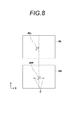
- the cursor 40L is fixed in one radiation image (here, GL), and the cursor 40R is moved in the direction of arrow C in FIG.
- the three-dimensional cursor can be moved in the depth direction in the stereoscopic image.
- the three-dimensional cursor in the stereoscopic image moves in a direction that bisects the angle formed by the imaging direction when two radiation images are acquired.
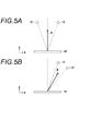
- FIG. 5 is a diagram for explaining the movement of the three-dimensional cursor in the stereoscopic image in the depth direction.
- the movement direction on the real space is equally dividing the angle (convergence angle) formed by the imaging directions when two radiation images are acquired Along the direction of Therefore, as shown in FIG. 5A, the position of the radiation source 17 at the time of acquiring two radiation images for displaying a stereoscopic image is a direction (Z direction) perpendicular to the radiation detector 15.
- the moving direction coincides with the Z direction in the real space, as shown by arrow A, when the three-dimensional cursor is moved in the depth direction.
- the position of the radiation source 17 at the time of acquiring two radiation images for displaying a stereoscopic image is a vertical line passing through the center of the radiation detector 15 serving as a reference at the time of imaging.
- the movement direction in the real space is a direction that bisects the convergence angle as shown by the arrow B.
- the movement direction of the three-dimensional cursor does not coincide with the Z direction in real space.
- the operation of the three-dimensional cursor becomes very uncomfortable.
- the position of the lesion in the subject is pinpointed because the needle is pierced in a direction perpendicular to the radiation detector in real space. If the three-dimensional cursor is moved in the depth direction to do so, the position of the lesion may not be accurately determined if the movement direction and the direction perpendicular to the radiation detector in real space do not match. .
- the present invention has been made in view of the above circumstances, and it is an object of the present invention to make the movement in at least one axis direction such as the depth direction of a three-dimensional cursor in a stereoscopic image coincide with the movement in real space.
- a radiation image display apparatus includes a display unit for displaying a stereoscopic image of two radiation images acquired by imaging an object from two directions having a predetermined convergence angle to display a stereoscopic image.
- a cursor is provided with a predetermined shift amount to each of the two radiation images, and a three-dimensional cursor for designating a position on the stereoscopic image is displayed on the stereoscopic image, and at least one of the three-dimensional cursors is displayed.
- a cursor display control unit for matching the axial movement with the movement in the real space.
- the cursor display control unit may make the movement direction of the depth of the three-dimensional cursor on the stereoscopic image coincide with the depth direction at the time of imaging of the subject.
- the cursor display control unit may change the movement of the three-dimensional cursor by changing the movement ratio of the cursor in each of the two radiation images.
- the cursor display control unit may calculate the movement ratio based on the predetermined convergence angle, the radiation source distance, and the display range of the stereoscopic image in the direction of the predetermined shift amount.
- the radiation image display method displays a stereoscopic image of two radiation images acquired by imaging an object from two directions having a predetermined convergence angle in order to display a stereoscopic image.
- a cursor is provided with a predetermined shift amount to each of the radiation images, and a three-dimensional cursor for designating a position on the stereoscopic image is displayed on the stereoscopic image, and at least one axial direction of the three-dimensional cursor is displayed. Is characterized in that it is changed to match the movement in the real space.
- the present invention provides a cursor with a predetermined shift amount for each of two radiation images, and displays a three-dimensional cursor for specifying a position on the stereoscopic image on the stereoscopic image, at this time.
- the motion of at least one axis of the three-dimensional cursor is changed to match the motion in the real space. Therefore, when specifying an object using a three-dimensional cursor on a stereoscopic image, the three-dimensional cursor can be moved in the same manner as in real space. Therefore, while being able to reduce the sense of incongruity when moving the three-dimensional cursor, it is possible to accurately specify the position in the depth direction of the object included in the stereoscopic image.
- the position of the object in the depth direction of the subject using the three-dimensional cursor Identification can be performed more accurately.
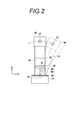
- photography display system using one Embodiment of the radiographic image display apparatus of this invention A view of the arm unit of the stereo mammogram display system shown in FIG. 1 as viewed from the right of FIG.
- FIG. 1 is a schematic block diagram of a breast imaging and display system to which a radiation image display apparatus according to an embodiment of the present invention is applied.
- the breast imaging and display system 1 captures a plurality of radiation images by imaging the breast M from different imaging directions in order to display a stereo image of the radiation image of the breast.
- the breast imaging and display system 1 includes an imaging unit 10, a computer 8 connected to the imaging unit 10, a monitor 3 (display unit) connected to the computer 8, and an input unit 4.
- the imaging unit 10 is movable with respect to the base 11 and the base 11 in the vertical direction (Z direction), and the rotatable shaft 12 is rotatable, and the arm unit 13 is connected to the base 11 by the rotary shaft 12.
- Have. 2 shows the arm portion 13 as viewed from the right of FIG.
- the arm unit 13 is in the shape of an alphabet C, and the radiation irradiating unit 16 is attached to one end of the arm unit 13 so as to face the imaging table 14 at the other end.
- the rotation and vertical movement of the arm unit 13 are controlled by an arm controller 31 incorporated in the base 11.
- a radiation detector 15 such as a flat panel detector and a detector controller 33 that controls readout of the charge signal from the radiation detector 15 are provided.
- a charge amplifier that converts the charge signal read from the radiation detector 15 into a voltage signal
- a correlated double sampling circuit that samples the voltage signal output from the charge amplifier
- a voltage signal A circuit board or the like provided with an AD conversion unit or the like for converting into a digital signal
- the imaging table 14 is configured to be rotatable with respect to the arm unit 13, and even when the arm unit 13 rotates with respect to the base 11, the direction of the imaging table 14 is fixed to the base 11. can do.
- the radiation detector 15 can repeat recording and readout of a radiation image, and may use a so-called direct type radiation detector which directly receives radiation to generate electric charge, or radiation May be converted into visible light, and the visible light may be converted into charge signals, so-called indirect radiation detectors may be used. Further, as a method of reading a radiation image signal, a so-called TFT reading method in which a radiation image signal is read by turning on and off a TFT (thin film transistor) switch, a radiation image signal by irradiating a reading light Although it is desirable to use a so-called light reading method in which is read out, the invention is not limited to this, and another one may be used.
- a radiation source 17 and a radiation source controller 32 are housed inside the radiation irradiator 16.
- the radiation source controller 32 controls the timing of irradiating radiation from the radiation source 17 and radiation generation conditions (tube current, time, tube voltage, etc.) in the radiation source 17.
- a compression plate 18 disposed above the imaging table 14 for pressing and compressing the breast M, a support 20 for supporting the compression plate 18, and the support 20 in the vertical direction A moving mechanism 19 for moving in the Z direction) is provided. The position of the compression plate 18 and the compression pressure are controlled by the compression plate controller 34.
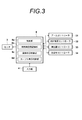
- the computer 8 is provided with a central processing unit (CPU) and storage devices such as a semiconductor memory, a hard disk, an SSD, etc., and a hardware such as the control unit 8a, the radiation image storage unit 8b as shown in FIG.
- a display control unit 8c and a cursor display control unit 8d are configured.
- the control unit 8a outputs predetermined control signals to various controllers 31 to 34 to control the entire apparatus. The specific control method will be described later.
- the radiation image storage unit 8 b stores two radiation images detected by the radiation detector 15 by imaging from two different imaging directions.
- the image display control unit 8c causes the monitor 3 to display a stereo image using two radiation images read from the radiation image storage unit 8b.
- the cursor display control unit 8 d displays a three-dimensional cursor described later on the stereo image displayed on the monitor 3 and moves the three-dimensional cursor according to an instruction from the input unit 4 by the operator. Details of control of display of the three-dimensional cursor will be described later.
- the monitor 3 is configured to be able to three-dimensionally display a stereo image using two radiation images output from the computer 8.
- a method of three-dimensional display of the monitor 3 for example, two radiation images are displayed using two screens, respectively, and one of the radiation images is the right eye of the observer by using a half mirror, a polarizing glass, etc. It is possible to adopt a method of displaying a stereo image by being incident on the other radiation image by being incident on the left eye of the observer. Alternatively, a method of displaying a stereo image by superimposing two radiation images and observing this with a polarizing glass may be used.
- the monitor 3 may be configured of 3D liquid crystal, and a method capable of stereoscopically viewing two radiation images, such as a parallax barrier method and a lenticular method may be used.
- the input unit 4 includes, for example, a keyboard and a pointing device such as a mouse, and receives an input of shooting conditions and the like, an input of a shooting start instruction, an input of movement of a cursor, and the like by an operator.
- imaging is performed as follows. First, the patient's breast M is placed on the imaging table 14, and the breast M is compressed by the compression plate 18 by a predetermined pressure. Next, after various imaging conditions are input in the input unit 4, an instruction to start imaging is input.
- the control unit 8a reads the initial imaging direction and convergence angle stored, and outputs the read information of the convergence angle to the arm controller 31. Then, in the arm controller 31, the information on the initial imaging direction and the convergence angle output from the control unit 8a is received, and the arm controller 31 first receives an image of the arm unit 13 as shown in the phantom line of FIG. A control signal is output so as to rotate by ⁇ 1 degrees in a direction (0 degree direction) perpendicular to 14.
- the control unit 8a irradiates the radiation source controller 32 and the detector controller 33 with radiation irradiation and a radiation image.
- a control signal is output to read out the signal.
- radiation is emitted from the radiation source 17, and a radiation image obtained by imaging the breast M from the direction of ⁇ 1 is detected by the radiation detector 15, and the detector controller 33 detects a radiation image signal from the radiation detector 15. Is read out and subjected to predetermined signal processing on the radiation image signal, and then stored in the radiation image storage unit 8b of the computer 8 as a radiation image GR for the right eye.
- the arm controller 31 outputs a control signal such that the arm unit 13 is rotated by ⁇ 2 degrees larger than ⁇ 1 degree with respect to the direction perpendicular to the photographing table 14. Then, in a state in which the arm unit 13 is rotated by ⁇ 2 degrees in accordance with the control signal output from the arm controller 31, the control unit 8a controls the radiation source controller 32 and the detector controller 33 to emit radiation and a radiation image signal. Output a control signal to read out In response to the control signal, radiation is emitted from the radiation source 17, a radiation image obtained by imaging the breast M from the ⁇ 2 direction is detected by the radiation detector 15, and a radiation image signal is read out by the detector controller 33. After the signal processing is performed, the radiation image storage unit 8b of the computer 8 stores the radiation image GL for the left eye.
- the two radiation images GR and GL stored in the radiation image storage unit 8 b are read out, subjected to predetermined processing on the radiation images GR and GL, and then output to the monitor 3.
- a stereo image of the breast M is displayed.
- a three-dimensional cursor is displayed on the monitor 3.
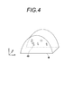
- FIG. 4 is a view showing a state in which a three-dimensional cursor is displayed on a stereo image of a breast.
- the three-dimensional coordinate system of XYZ similar to FIGS. 1 and 2 is used to show the depth and the breast M is shown using a perspective view, actually, the breast M and the breast M are shown.
- the three-dimensional cursor is to be viewed stereoscopically.
- the breast M to be stereoscopically viewed is flat on the near side and the rear side. This is because the breast M is compressed between the compression plate 18 and the imaging table 14 at the time of imaging.
- the three-dimensional cursor 40 is in the form of an arrow, and can move not only in the plane direction (XY direction) of the stereo image but also in the depth direction (Z direction). In the present embodiment, the position in the depth direction can be changed by operating the arrow key of the keyboard of the input unit 4 or the wheel of the mouse.
- the shape of the three-dimensional cursor 40 is not limited to the arrow, and other shapes such as a sphere and a cone may be used.
- the three-dimensional cursor 40 is three-dimensionally displayed by the same method as the stereo image so as to have a three-dimensional effect according to the position in the depth direction. Specifically, an arrow-shaped cursor is added to each of the radiation images GR and GL by a shift amount according to the three-dimensional effect, and a stereo image of the radiation images GR and GL to which the cursor is added is displayed. As a result, the cursor is displayed three-dimensionally together with the radiation image.
- the position of the radiation source 17 at the time of obtaining two radiation images GR and GL for displaying a stereo image is the center of the radiation detector 15 serving as a reference at the time of imaging.
- the movement direction in the real space is a direction that bisects the convergence angle as shown by arrow B.
- the moving direction of the dimensional cursor 40 does not coincide with the direction of the Z axis in real space.
- the operation of the three-dimensional cursor 40 becomes very uncomfortable.
- the cursor display control unit 8d causes the movement direction of the depth of the three-dimensional cursor 40 on the stereo image to coincide with the depth direction at the time of imaging of the breast M, that is, the Z direction.
- the display of the three-dimensional cursor is controlled.
- control of display of the three-dimensional cursor will be described.
- FIG. 6 is a diagram for explaining the movement of the three-dimensional cursor.
- the convergence angle at the time of acquiring two radiation images GR and GL is ⁇ 2- ⁇ 1.
- the cursor 40L is fixed in one radiation image GL, and the cursor 40R is moved in the direction of arrow C (X direction) in FIG. 8 in the other radiation image GR.
- the three-dimensional cursor 40 to be moved is moved in the depth direction, the three-dimensional cursor 40 moves in a direction that bisects the convergence angle in the real space.
- the distance ⁇ between the radiation sources 17 at two imaging positions of the radiation source 17 at the time of imaging can be calculated by the following equation (1), where the source distance is SID.
- ⁇ 2 ⁇ SID ⁇ sin ⁇ ( ⁇ 2 ⁇ 1) / 2 ⁇ (1)
- the cursor 40L displayed on one of the radiation images GL of the radiation images GR and GL is fixed, and the cursor 40R displayed on the other radiation image GR is an arrow C in FIG.
- the angle at which the moving direction of the three-dimensional cursor 40 makes with the display surface of the monitor 3 on the stereo image Assuming that the display range of the stereo image in the X direction on the monitor 3 is ⁇ , ⁇ 0 can be calculated by the following equation (2).
- the cursor display control unit 8d sets the movement ratio (movement ratio) of the cursors 40R and 40L in each of the two radiation images GR and GL to 1 : Move in the same direction of the X direction as ⁇ / ⁇ 0. That is, when the moving distance of the cursor 40R is 1, the moving distance of the cursor 40L is ⁇ / ⁇ 0. As a result, when the three-dimensional cursor 40 is moved in the depth direction, the moving direction coincides with the Z direction in real space.
- the three-dimensional cursor 40 when the three-dimensional cursor 40 is displayed on the stereo image and there is a movement instruction in the depth direction, the two radiation images GR and GL for displaying the stereo image are displayed.
- the movement of the cursor given to each is controlled to make the movement direction of the three-dimensional cursor coincide with the Z-axis direction in real space. For this reason, when specifying an object using a three-dimensional cursor on a stereo image, the three-dimensional cursor can be moved in the same manner as in real space, thus reducing the discomfort when moving the three-dimensional cursor. While being able to do, it is possible to specify the position of the object in the depth direction with high accuracy.
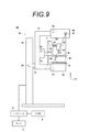
- FIG. 9 is a diagram showing the configuration of a breast imaging and display system to which a biopsy unit is attached.
- the same components as those of the breast imaging and display system 1 shown in FIG. 1 are given the same reference numerals, and the detailed description thereof is omitted here.
- the breast imaging and display system 1A shown in FIG. 9 includes a biopsy unit 2 and has a size of about 10 ⁇ 10 cm so that the compression plate 18 can perform a biopsy with the breast fixed by the imaging table 14 and the compression plate 18. This embodiment differs from the breast imaging and display system 1 shown in FIG.
- the mammography display system 1A is mechanically and electrically It is connected.
- the biopsy unit 2 has a biopsy needle 21 which is punctured in the breast M, and is constituted of a biopsy needle unit 22 configured to be detachable, a needle support 23 for supporting the biopsy needle unit 22, and a needle support 23
- a moving mechanism 24 is provided for moving the biopsy needle unit 22 in the X, Y and Z directions shown in FIGS. 1 and 2 by moving along the rails or moving the needle support 23 in and out.
- the position of the tip of the biopsy needle 21 of the biopsy needle unit 22 is recognized and controlled as position coordinates (x, y, z) in a three-dimensional space by the needle position controller 35 provided in the moving mechanism 24.
- a stereo image is displayed on the monitor 3
- an abnormal shadow target is designated by the operator
- position information (x, y, z) of the designated target is the control unit 8a.
- the controller 8a outputs the position information to the needle position controller 35 of the biopsy unit 2.
- a control signal for moving the biopsy needle 21 is output from the control unit 8a to the needle position controller 35.
- the needle position controller 35 moves the biopsy needle 21 so that the tip of the biopsy needle 21 is disposed above the position indicated by the coordinates based on the value of the position information input earlier.
- the position where the tip of the biopsy needle 21 shows the coordinates
- the biopsy needle 21 is moved so as to be placed in the breast and the breast is punctured by the biopsy needle 21.
- the convergence angle at the time of acquiring two radiation images GR and GL needs to be very large as ⁇ 10 degrees to ⁇ 15 degrees.
- the position of the radiation source 17 at the time of acquiring two radiation images for displaying a stereo image is at a target position across the axis in the direction (Z direction) perpendicular to the radiation detector 15
- the dimensional cursor is moved in the depth direction
- shooting with a shooting direction of 0 degrees and +15 degrees is also performed. In such a case, when the three-dimensional cursor is moved in the depth direction, the movement direction is Z in real space. It does not match the direction.
- the ratio of the movement of the cursor given to each of the two radiation images GR and GL is set to be 1: .theta ./. Theta.0 so as to move in the same direction in the X direction.
- the three-dimensional cursor can be moved in the same manner as in real space, so that the sense of discomfort when moving the three-dimensional cursor can be reduced.
- the lesion in the subject is pricked with a needle in a direction (Z direction) perpendicular to the radiation detector in real space. If the movement in the depth direction of the three-dimensional cursor to do so does not coincide with the direction perpendicular to the radiation detector in real space, the lesion may not be identified with high accuracy.
- the three-dimensional cursor when specifying an object using a three-dimensional cursor on a stereo image, the three-dimensional cursor can be moved in the same manner as in real space, so Identification can be performed with high accuracy.
- one embodiment of the radiation image display apparatus of the present invention is applied to a stereo mammogram imaging and display system, but the subject of the present invention is not limited to the breast.
- the present invention can also be applied to a radiographic imaging and display system for imaging a part or the like.
- angles ⁇ 1 and ⁇ 2 formed by the imaging directions at the time of acquiring two radiation images are on the same side with respect to a perpendicular passing through the center of the radiation detector 15 serving as a reference at imaging.
Landscapes
- Health & Medical Sciences (AREA)
- Life Sciences & Earth Sciences (AREA)
- Engineering & Computer Science (AREA)
- Medical Informatics (AREA)
- Pathology (AREA)
- Heart & Thoracic Surgery (AREA)
- High Energy & Nuclear Physics (AREA)
- Physics & Mathematics (AREA)
- Nuclear Medicine, Radiotherapy & Molecular Imaging (AREA)
- Optics & Photonics (AREA)
- Veterinary Medicine (AREA)
- Radiology & Medical Imaging (AREA)
- Biomedical Technology (AREA)
- Biophysics (AREA)
- Molecular Biology (AREA)
- Surgery (AREA)
- Animal Behavior & Ethology (AREA)
- General Health & Medical Sciences (AREA)
- Public Health (AREA)
- Human Computer Interaction (AREA)
- Dentistry (AREA)
- Oral & Maxillofacial Surgery (AREA)
- Apparatus For Radiation Diagnosis (AREA)
Abstract
立体視画像における3次元カーソルの奥行き方向等の少なくとも1軸方向の動きを、実空間上の動きと一致させる。モニタ3にステレオ画像を表示するとともに、3次元カーソルを表示する。3次元カーソルを奥行き方向に移動させるに際し、ステレオ画像上における3次元カーソルの奥行きについての移動方向を、被検体の撮影時における奥行き方向と一致させる。
Description
本発明は、被検体の立体視画像を表示する放射線画像表示装置および方法に関するものである。
従来、複数の画像を組み合わせて表示することにより、視差を利用して立体視できることが知られている。このような立体視できる画像(以下、立体視画像またはステレオ像という)は、同一の被写体を異なる方向から撮影して取得された複数の画像を用いて表示される。
一方、このような立体視画像は、デジタルカメラやテレビ等の分野だけでなく、放射線画像撮影の分野においても利用されている。すなわち、被検体に対して異なる撮影方向から放射線を照射し、その被検体を透過した放射線を放射線検出器によりそれぞれ検出して左目用および右目用の放射線画像を取得し、これらの放射線画像を用いて立体視画像を表示することが行われている。このような立体視画像を用いることにより、奥行き感のある放射線画像を観察することができるため、診断をより行いやすくすることができる。
ところで、病院の検査では病変周辺の組織片を採取することがあるが、近年、患者に大きな負担をかけずに組織片を採取する方法として、中が空洞の組織採取用の針(以下、生検針と称する)を患者に刺し、針の空洞に埋め込まれた組織を採取するバイオプシが注目されている。そして、このようなバイオプシを行うための装置としてステレオバイオプシ装置が提案されている。
このステレオバイオプシ装置は、被検体の立体視画像を観察しながら病変の3次元的な位置を特定することができ、生検針の先端をその特定位置に到達するよう制御することによって所望の位置から組織片を採取することができるものである。
一方、放射線画像は被検体内部の透過画像であることから、被検体の内部にある骨、各種組織および腫瘤や石灰化等の病変等の構造物が重なり合った状態で含まれている。このため、放射線画像を用いて立体視画像を表示した場合において、平面方向のみならず奥行き方向にも移動可能な3次元カーソルを用いて、必要な指示を画像上において行うようにしている。3次元カーソルは立体視画像を表示するための2つの放射線画像上において、所定のシフト量を持って付与され、シフト量を変更することにより、立体視画像の奥行き方向に3次元カーソルを移動させることができる(特許文献1参照)。また、立体視画像を表示するための2つの放射線画像上におけるカーソルのシフト量を変更することにより、3次元カーソルを立体視画像上において自由に移動させる手法が提案されている(特許文献2参照)。
ここで、3次元カーソルを奥行き方向に移動させるためには、図8に示すように2つの放射線画像GR,GLにおいて、カーソルのシフト量を変更することが必要となる。すなわち、3次元カーソルを奥行き方向にのみ移動させるには、一方の放射線画像(ここではGLとする)においてカーソル40Lを固定し、他方の放射線画像GRにおいてカーソル40Rを図8の矢印Cの方向にシフトさせることにより、立体視画像において3次元カーソルを奥行き方向に移動させることができる。この際、立体視画像における3次元カーソルは、実空間上においては、2つの放射線画像を取得した際の撮影方向がなす角度を2等分する方向に移動することとなる。
図5は立体視画像における3次元カーソルの奥行き方向の動きを説明するための図である。立体視画像に表示された3次元カーソルを奥行き方向に移動させた場合、その実空間上での移動方向は、2つの放射線画像を取得した際の撮影方向がなす角度(輻輳角)を2等分する方向に沿うものとなる。このため、図5(a)に示すように立体視画像を表示するための2つの放射線画像を取得した際の放射線源17の位置が、放射線検出器15に対して垂直な方向(Z方向)の軸を挟んで対象な位置にある場合、3次元カーソルを奥行き方向に移動させると、その移動方向は矢印Aに示すように実空間上におけるZ方向と一致する。
しかしながら、図5(b)に示すように立体視画像を表示するための2つの放射線画像を取得した際の放射線源17の位置が、撮影時の基準となる放射線検出器15の中心を通る垂線に対して同じ側にある場合、3次元カーソルを奥行き方向に移動させると、その実空間上における移動方向は矢印Bに示すように輻輳角を2等分する方向となる。このため、3次元カーソルの移動方向が実空間上のZ方向と一致しなくなる。このように、3次元カーソルを奥行き方向に移動させた場合に、その移動方向が実空間上のZ方向と一致しなくなると、3次元カーソルの操作が非常に違和感を有するものとなる。
さらに、違和感のみならず、3次元カーソルを用いての、立体視画像に含まれる病変の実空間上における奥行き方向の位置の特定が困難なものとなる。とくに上述したステレオバイオプシ装置においては、立体視画像を観察しつつ、被検体内の病変に対して実空間上における放射線検出器に垂直な方向に針を刺すこととなるため、病変の位置を特定するために3次元カーソルを奥行き方向に移動させた場合、その移動方向と実空間上の放射線検出器に垂直な方向とが一致していないと、病変の位置を精度良く特定できなくなるおそれがある。
本発明は上記事情に鑑みなされたものであり、立体視画像における3次元カーソルの奥行き方向等の少なくとも1軸方向の動きを、実空間上の動きと一致させることを目的とする。
本発明による放射線画像表示装置は、立体視画像を表示するために所定の輻輳角となる2方向から被検体を撮影して取得された、2つの放射線画像の立体視画像を表示する表示部と、
2つの放射線画像のそれぞれに所定のシフト量を持ってカーソルを付与して、立体視画像上に立体視画像上の位置を指定するための3次元カーソルを表示し、この3次元カーソルの少なくとも1軸方向の動きを、実空間上の動きと一致させるカーソル表示制御部とを備えたものである。
2つの放射線画像のそれぞれに所定のシフト量を持ってカーソルを付与して、立体視画像上に立体視画像上の位置を指定するための3次元カーソルを表示し、この3次元カーソルの少なくとも1軸方向の動きを、実空間上の動きと一致させるカーソル表示制御部とを備えたものである。
なお、本発明による放射線画像表示装置においては、カーソル表示制御部を、立体視画像上における3次元カーソルの奥行きについての移動方向を、被検体の撮影時における奥行き方向と一致させてもよい。
また、本発明による放射線画像表示装置においては、カーソル表示制御部を、2つの放射線画像のそれぞれにおけるカーソルの移動の比率を変更して、3次元カーソルの動きを変更してもよい。
この場合、カーソル表示制御部を、移動の比率を所定の輻輳角、線源距離および所定のシフト量の方向における立体視画像の表示範囲に基づいて算出してもよい。
本発明による放射線画像表示方法は、立体視画像を表示するために所定の輻輳角となる2方向から被検体を撮影して取得された、2つの放射線画像の立体視画像を表示し、2つの放射線画像のそれぞれに所定のシフト量を持ってカーソルを付与して、立体視画像上に立体視画像上の位置を指定するための3次元カーソルを表示し、この3次元カーソルの少なくとも1軸方向の動きを、実空間上の動きと一致させるよう変更することを特徴とするものである。
本発明は、2つの放射線画像のそれぞれに所定のシフト量を持ってカーソルを付与して、立体視画像上に立体視画像上の位置を指定するための3次元カーソルを表示し、この際に、3次元カーソルの少なくとも1軸方向の動きを実空間上の動きと一致させるよう変更するようにしたものである。このため、立体視画像上において3次元カーソルを用いての物体を特定する際に、3次元カーソルを実空間上と同じように移動させることができる。したがって、3次元カーソルを移動させる際の違和感を軽減できるとともに、立体視画像に含まれる物体の奥行き方向における位置の特定を精度良く行うことができる。
とくに、立体視画像上における3次元カーソルの奥行きについての移動方向を、被検体の撮影時における奥行き方向と一致させることにより、3次元カーソルを用いての被検体内の物体の奥行き方向の位置の特定をより精度良く行うことができる。
以下、図面を参照して本発明の実施形態について説明する。図1は本発明の実施形態による放射線画像表示装置を適用した乳房画像撮影表示システムの概略構成図である。乳房画像撮影表示システム1は、乳房の放射線画像のステレオ画像を表示するために、異なる撮影方向から乳房Mを撮影して複数の放射線画像を取得するものである。図1に示すように乳房画像撮影表示システム1は、撮影部10、撮影部10に接続されたコンピュータ8、コンピュータ8に接続されたモニタ3(表示部)および入力部4を備えている。
撮影部10は、基台11、基台11に対し上下方向(Z方向)に移動可能であり、かつ回転可能な回転軸12、および回転軸12により基台11と連結されたアーム部13を備えている。なお、図2には図1の右方向から見たアーム部13を示している。
アーム部13はアルファベットのCの形をしており、その一端には撮影台14が、その他端には撮影台14と対向するように放射線照射部16が取り付けられている。アーム部13の回転および上下方向の移動は、基台11に組み込まれたアームコントローラ31により制御される。
撮影台14の内部には、フラットパネルディテクタ等の放射線検出器15、および放射線検出器15からの電荷信号の読み出しを制御する検出器コントローラ33が備えられている。
また、撮影台14の内部には、放射線検出器15から読み出された電荷信号を電圧信号に変換するチャージアンプ、チャージアンプから出力された電圧信号をサンプリングする相関2重サンプリング回路、電圧信号をデジタル信号に変換するAD変換部等が設けられた回路基板等も設置されている。
また、撮影台14はアーム部13に対し回転可能に構成されており、基台11に対してアーム部13が回転したときでも、撮影台14の向きは基台11に対し固定された向きとすることができる。
放射線検出器15は、放射線画像の記録および読み出しを繰り返して行うことができるものであり、放射線の照射を直接受けて電荷を発生する、いわゆる直接型の放射線検出器を用いてもよいし、放射線を一旦可視光に変換し、その可視光を電荷信号に変換する、いわゆる間接型の放射線検出器を用いるようにしてもよい。また、放射線画像信号の読出方式としては、TFT(thin film transistor)スイッチをオン・オフさせることによって放射線画像信号が読み出される、いわゆるTFT読出方式のものや、読取光を照射することによって放射線画像信号が読み出される、いわゆる光読出方式のものを用いることが望ましいが、これに限らずその他のものを用いるようにしてもよい。
放射線照射部16の内部には、放射線源17および放射線源コントローラ32が収納されている。放射線源コントローラ32は、放射線源17から放射線を照射するタイミングと、放射線源17における放射線発生条件(管電流、時間、管電圧等)とを制御するものである。
また、アーム部13の中央部には、撮影台14の上方に配置されて乳房Mを押さえつけて圧迫する圧迫板18、その圧迫板18を支持する支持部20、および支持部20を上下方向(Z方向)に移動させる移動機構19が設けられている。圧迫板18の位置および圧迫圧は、圧迫板コントローラ34により制御される。
コンピュータ8は、中央処理装置(CPU)および半導体メモリやハードディスクやSSD等のストレージデバイス等を備えており、これらのハードウェアによって、図3に示すような制御部8a、放射線画像記憶部8b、画像表示制御部8c、およびカーソル表示制御部8dが構成されている。
制御部8aは、各種のコントローラ31~34に対して所定の制御信号を出力し、装置全体の制御を行うものである。具体的な制御方法については後述する。
放射線画像記憶部8bは、互いに異なる2つの撮影方向からの撮影によって放射線検出器15により検出された2枚の放射線画像を記憶するものである。
画像表示制御部8cは、放射線画像記憶部8bから読み出された2枚の放射線画像を用いたステレオ画像をモニタ3に表示させるものである。
カーソル表示制御部8dは、モニタ3に表示されたステレオ画像に、後述する3次元カーソルを表示させ、操作者による入力部4からの指示により、3次元カーソルを移動させるものである。3次元カーソルの表示の制御の詳細については後述する。
モニタ3は、コンピュータ8から出力された2つの放射線画像を用いてステレオ画像を3次元表示可能なように構成されたものである。モニタ3の3次元表示の方式としては、例えば、2つの画面を用いて2つの放射線画像をそれぞれ表示させて、これらをハーフミラーや偏光グラス等を用いることで一方の放射線画像は観察者の右目に入射させ、他方の放射線画像は観察者の左目に入射させることによってステレオ画像を表示する方式を採用することができる。また、2つの放射線画像を重ね合わせ、これを偏光グラスで観察することでステレオ画像を表示する方式を用いてもよい。さらに、モニタ3を3D液晶により構成し、パララックスバリア方式およびレンチキュラー方式のように、2つの放射線画像を立体視可能な方式を用いてもよい。
入力部4は、例えば、キーボードおよびマウス等のポインティングデバイスから構成されるものであり、操作者による撮影条件等の入力、撮影開始指示の入力、カーソルの移動の入力等を受け付けるものである。
このような放射線画像撮影装置1においては、以下のようにして撮影が行われる。まず、撮影台14の上に患者の乳房Mが設置され、圧迫板18により乳房Mが所定の圧力によって圧迫される。次に、入力部4において、種々の撮影条件が入力された後、撮影開始の指示が入力される。
入力部4において撮影開始の指示があると、ステレオ画像を表示するための2つの放射線画像の撮影が行われる。具体的には、まず、制御部8aが記憶された初期の撮影方向および輻輳角を読み出し、その読み出した輻輳角の情報をアームコントローラ31に出力する。そして、アームコントローラ31において、制御部8aから出力された初期の撮影方向および輻輳角の情報が受け付けられ、アームコントローラ31は、まず、図2の仮想線に示すように、アーム部13が撮影台14に垂直な方向(0度方向)に対してθ1度回転するように制御信号を出力する。
そして、このアームコントローラ31から出力された制御信号に応じて、アーム部13がθ1度回転した状態において、制御部8aは、放射線源コントローラ32および検出器コントローラ33に対して放射線の照射および放射線画像信号の読み出しを行うよう制御信号を出力する。この制御信号に応じて、放射線源17から放射線が射出され、乳房Mをθ1度の方向から撮影した放射線画像が放射線検出器15によって検出され、検出器コントローラ33によって放射線検出器15から放射線画像信号が読み出され、その放射線画像信号に対して所定の信号処理が施された後、コンピュータ8の放射線画像記憶部8bに右目用の放射線画像GRとして記憶される。
次に、アームコントローラ31は、アーム部13を撮影台14に垂直な方向に対してθ1度よりも大きいθ2度回転するよう制御信号を出力する。そして、このアームコントローラ31から出力された制御信号に応じてアーム部13がθ2度回転した状態において、制御部8aは、放射線源コントローラ32および検出器コントローラ33に対して放射線の照射および放射線画像信号の読み出しを行うよう制御信号を出力する。この制御信号に応じて、放射線源17から放射線が射出され、乳房Mをθ2度方向から撮影した放射線画像が放射線検出器15によって検出され、検出器コントローラ33によって放射線画像信号が読み出され、所定の信号処理が施された後、コンピュータ8の放射線画像記憶部8bに左目用の放射線画像GLとして記憶される。
そして、放射線画像記憶部8bに記憶された2つの放射線画像GR,GLが読み出され、放射線画像GR,GLに対して所定の処理が施された後、モニタ3に出力され、モニタ3において、乳房Mのステレオ画像が表示される。また、これとともにモニタ3に3次元カーソルが表示される。
図4は乳房のステレオ画像に3次元カーソルが表示された状態を示す図である。なお、図4においては奥行きを示すために、図1,2と同様のXYZの3次元の座標系を使用し、乳房Mを斜視図を用いて示しているが、実際には、乳房Mおよび3次元カーソルは、立体視されるものである。
図4に示すように、立体視される乳房Mは、手前側および後側は平面となっている。これは、撮影時には圧迫板18と撮影台14との間において乳房Mが圧迫されているためである。また、3次元カーソル40は矢印形状をなしており、ステレオ画像の平面方向(XY方向)のみならず奥行き方向(Z方向)にも移動可能なカーソルである。本実施形態においては、入力部4のキーボードの矢印キーあるいはマウスのホイール等を操作することにより、奥行き方向の位置を変更可能となっている。ここで、3次元カーソル40の形状は矢印に限定されるものではなく、球形および円錐形等の他の形状のものを用いてもよい。ここで、3次元カーソル40は、奥行き方向の位置に応じた立体感となるように、ステレオ画像と同様の方式により3次元表示される。具体的には、放射線画像GR,GLのそれぞれに対して、立体感に応じたシフト量にて矢印形状のカーソルを付与し、カーソルが付与された放射線画像GR,GLのステレオ画像を表示することにより、放射線画像とともにカーソルが3次元表示されることとなる。
ここで、図5(b)に示すようにステレオ画像を表示するための2つの放射線画像GR,GLを取得した際の放射線源17の位置が、撮影時の基準となる放射線検出器15の中心を通る垂線に対して同じ側にある場合、3次元カーソル40を奥行き方向に移動させると、その実空間上における移動方向は矢印Bに示すように輻輳角を2等分する方向となるため、3次元カーソル40の移動方向が実空間上のZ軸の方向と一致しなくなる。このように、3次元カーソル40の奥行きの移動方向が実空間上のZ軸の方向と一致しなくなると、3次元カーソル40の操作が非常に違和感を有するものとなる。とくに、3次元カーソル40の移動方向と実空間上のZ軸の方向のずれ角が5度を超えると、その違和感が顕著なものとなる。また、違和感のみならず、3次元カーソル40を用いての、ステレオ画像に含まれる病変の実空間上における奥行き方向の位置の特定が困難なものとなる。
このため、本実施形態においては、ステレオ画像上における3次元カーソル40の奥行きについての移動方向を、乳房Mの撮影時における奥行き方向、すなわちZ方向と一致させるように、カーソル表示制御部8dにより、3次元カーソルの表示が制御される。以下、3次元カーソルの表示の制御について説明する。
図6は3次元カーソルの動きを説明するための図である。図6に示すように、2つの放射線画像GR,GLを取得した際の輻輳角はθ2-θ1である。そして、図8に示すように、一方の放射線画像GLにおいてカーソル40Lを固定し、他方の放射線画像GRにおいてカーソル40Rを図8の矢印Cの方向(X方向)に移動させることにより、3次元表示される3次元カーソル40を奥行き方向に移動させる場合、3次元カーソル40は、実空間における輻輳角を2等分する方向に移動する。ここで、この方向が実空間のZ軸(すなわち放射線検出器15の垂線)となす角度をθとすると、θ=(θ1+θ2)/2となる。したがって、3次元カーソル40を実空間のZ方向に移動させるためには、ステレオ画像中の3次元カーソルの動きをθ度修正すればよいこととなる。なお、図6において、撮影時における放射線源17の2つの撮影位置における放射線源17間の距離αは、線源距離をSIDとすると、下記の式(1)により算出できる。
α=2×SID×sin{(θ2-θ1)/2} (1)
ここで、図8に示すように、放射線画像GR,GLのうちの一方の放射線画像GLに表示されるカーソル40Lを固定し、他方の放射線画像GRに表示されるカーソル40Rを図8の矢印C方向に移動させることにより3次元表示された3次元カーソル40を奥行き方向に移動させる場合、図7に示すように、ステレオ画像上において3次元カーソル40の移動方向がモニタ3の表示面となす角度θ0は、ステレオ画像のモニタ3上のX方向における表示範囲をβとすると、下記の式(2)により算出できる。
ここで、図8に示すように、放射線画像GR,GLのうちの一方の放射線画像GLに表示されるカーソル40Lを固定し、他方の放射線画像GRに表示されるカーソル40Rを図8の矢印C方向に移動させることにより3次元表示された3次元カーソル40を奥行き方向に移動させる場合、図7に示すように、ステレオ画像上において3次元カーソル40の移動方向がモニタ3の表示面となす角度θ0は、ステレオ画像のモニタ3上のX方向における表示範囲をβとすると、下記の式(2)により算出できる。
θ0=tan-1{(α+β)/(2・SID)} (2)
したがって、実空間上のZ方向に3次元カーソルを移動させる場合、カーソル表示制御部8dは、2つの放射線画像GR,GLのそれぞれにおけるカーソル40R,40Lの動きの比率(移動の比率)を、1:θ/θ0として、X方向の同一方向に移動させる。つまり、カーソル40Rの移動距離を1としたときに、カーソル40Lの移動距離はθ/θ0になる。これにより、3次元カーソル40を奥行き方向に移動させた場合、その移動方向は実空間上のZ方向に一致することとなる。
したがって、実空間上のZ方向に3次元カーソルを移動させる場合、カーソル表示制御部8dは、2つの放射線画像GR,GLのそれぞれにおけるカーソル40R,40Lの動きの比率(移動の比率)を、1:θ/θ0として、X方向の同一方向に移動させる。つまり、カーソル40Rの移動距離を1としたときに、カーソル40Lの移動距離はθ/θ0になる。これにより、3次元カーソル40を奥行き方向に移動させた場合、その移動方向は実空間上のZ方向に一致することとなる。
このように、本実施形態によれば、3次元カーソル40をステレオ画像上に表示し、その奥行き方向への移動指示があった場合、ステレオ画像を表示するための2つの放射線画像GR,GLのそれぞれに付与されるカーソルの動きを制御して、3次元カーソルの移動方向を実空間におけるZ軸方向と一致させるようにしたものである。このため、ステレオ画像上において3次元カーソルを用いての物体を特定する際に、3次元カーソルを実空間上と同じように移動させることができるため、3次元カーソルを移動させる際の違和感を軽減できるとともに、物体の奥行き方向の位置の特定を精度良く行うことができる。
なお、図1に示す乳房画像撮影表示システムにバイオプシユニットを取り付けて、乳房用のステレオバイオプシシステムとしても動作させることも可能である。図9はバイオプシユニットを取り付けた乳房画像撮影表示システムの構成を示す図である。なお、図9に示す乳房画像撮影表示システム1Aにおいて、図1に示す乳房画像撮影表示システム1と同一の構成については同一の参照番号を付与し、ここでは詳細な説明は省略する。
図9に示す乳房画像撮影表示システム1Aは、バイオプシユニット2を備え、圧迫板18が、撮影台14と圧迫板18により乳房を固定した状態でバイオプシを行えるよう、約10×10cm四方の大きさの開口部5を備えている点が図1に示す乳房画像撮影表示システム1と異なる。
バイオプシユニット2は、その基体部分が圧迫板18の支持部20の開口部に差し込まれ、基体部分の下端がアーム部13に取り付けられることによって、乳房画像撮影表示システム1Aと機械的、電気的に接続されるものである。そして、バイオプシユニット2は、乳房Mに穿刺される生検針21を有し、着脱可能に構成された生検針ユニット22と、生検針ユニット22を支持する針支持部23と、針支持部23をレールに沿って移動させ、あるいは針支持部23を出し入れさせることにより、生検針ユニット22を図1、図2に示すX、YおよびZ方向に移動させる移動機構24とを備える。生検針ユニット22の生検針21の先端の位置は、移動機構24が備える針位置コントローラ35により、3次元空間における位置座標(x,y,z)として認識され、制御される。
このような乳房画像撮影表示システム1Aにおいては、ステレオ画像をモニタ3に表示し、操作者によって異常陰影のターゲットが指定され、指定されたターゲットの位置情報(x,y,z)が制御部8aによって取得され、制御部8aがその位置情報をバイオプシユニット2の針位置コントローラ35に出力する。
この状態で、入力部4において所定の操作ボタンが押されると、制御部8aから針位置コントローラ35に対し、生検針21を移動させる制御信号が出力される。針位置コントローラ35は、先に入力された位置情報の値に基づき、生検針21の先端が、その座標の示す位置の上方に配置されるように、生検針21を移動する。
その後、操作者により、生検針21の穿刺を指示する所定の操作が入力部4において行われると、制御部8aと針位置コントローラ35の制御の下で、生検針21の先端が座標の示す位置に配置されるように生検針21が移動させられて、生検針21による乳房の穿刺が行われる。
このような乳房画像撮影表示システム1Aを用いてステレオバイオプシを行う場合、ターゲットの奥行き方向の指定を精度良く行うために、ステレオ画像の奥行き方向の解像度を大きくする必要がある。このため、2つの放射線画像GR,GLを取得する際の輻輳角は±10度~±15度のように非常に大きくする必要がある。ここで、ステレオ画像を表示するための2つの放射線画像を取得した際の放射線源17の位置が、放射線検出器15に対して垂直な方向(Z方向)の軸を挟んで対象な位置にある場合、次元カーソルを奥行き方向に移動させると、その移動方向は実空間上におけるZ方向と一致するため問題はない。しかしながら、ステレオバイオプシにおいては、撮影方向が0度と+15度のような撮影も行われ、このような場合には、3次元カーソルの奥行き方向に移動させると、その移動方向が実空間上のZ方向と一致しなくなる。
このため、上記と同様に、2つの放射線画像GR,GLのそれぞれに付与されるカーソルの動きの比率を、1:θ/θ0として、X方向の同一方向に移動させるようにすることにより、ステレオ画像上において3次元カーソルを用いての物体を特定する際に、3次元カーソルを実空間上と同じように移動させることができるため、3次元カーソルを移動させる際の違和感を軽減できる。
また、とくにステレオバイオプシにおいては、ステレオ画像を観察しつつ、被検体内の病変に対して実空間上における放射線検出器に垂直な方向(Z方向)に針を刺すこととなるため、病変を特定するための3次元カーソルの奥行き方向の動きと実空間上の放射線検出器に垂直な方向とが一致していないと、精度良く病変を特定できなくなるおそれがある。本実施形態によれば、ステレオ画像上において3次元カーソルを用いての物体を特定する際に、3次元カーソルを実空間上と同じように移動させることができるため、病変の奥行き方向における位置の特定を精度良く行うことができる。
なお、上記実施形態においては、本発明の放射線画像表示装置の一実施形態をステレオ乳房画像撮影表示システムに適用したものであるが、本発明の被写体としては乳房に限らず、例えば、胸部や頭部等を撮影する放射線画像撮影表示システムにも本発明を適用することができる。
また、上記実施形態においては、2つの放射線画像を取得する際の撮影方向がなす角度θ1,θ2を撮影時の基準となる放射線検出器15の中心を通る垂線に対して同じ側にあるものとしているが、例えばθ1=0として2つの放射線画像を取得するようにしてもよい。
1,1A 乳房画像撮影表示システム
2 バイオプシユニット
3 モニタ
4 入力部
8 コンピュータ
8a 制御部
8b 放射線画像記憶部
8c 画像表示制御部
8d カーソル表示制御部
10 撮影部
13 アーム部
14 撮影台
15 放射線検出器
16 放射線照射部
17 放射線源
18 圧迫板
2 バイオプシユニット
3 モニタ
4 入力部
8 コンピュータ
8a 制御部
8b 放射線画像記憶部
8c 画像表示制御部
8d カーソル表示制御部
10 撮影部
13 アーム部
14 撮影台
15 放射線検出器
16 放射線照射部
17 放射線源
18 圧迫板
Claims (5)
- 立体視画像を表示するために所定の輻輳角となる2方向から被検体を撮影して取得された、2つの放射線画像の前記立体視画像を表示する表示部と、
前記2つの放射線画像のそれぞれに所定のシフト量を持ってカーソルを付与して、前記立体視画像上に前記立体視画像上の位置を指定するための3次元カーソルを表示し、該3次元カーソルの少なくとも1軸方向の動きを実空間上の動きと一致させるカーソル表示制御部とを備えた放射線画像表示装置。 - 前記カーソル表示制御部は、前記立体視画像上における前記3次元カーソルの奥行きについての移動方向を、前記被検体の撮影時における奥行き方向と一致させる請求項1記載の放射線画像表示装置。
- 前記カーソル表示制御部は、前記2つの放射線画像のそれぞれにおける前記カーソルの移動の比率を変更して、前記3次元カーソルの動きを変更する請求項1または2記載の放射線画像表示装置。
- 前記カーソル表示制御部は、前記移動の比率を前記所定の輻輳角、線源距離および前記所定のシフト量の方向における前記立体視画像の表示範囲に基づいて算出する請求項1から3のいずれか1項記載の放射線画像表示装置。
- 立体視画像を表示するために所定の輻輳角となる2方向から被検体を撮影して取得された、2つの放射線画像の前記立体視画像を表示し、
前記2つの放射線画像のそれぞれに所定のシフト量を持ってカーソルを付与して、前記立体視画像上に前記立体視画像上の位置を指定するための3次元カーソルを表示し、
該3次元カーソルの少なくとも1軸方向の動きを、実空間上の動きと一致させる放射線画像表示方法。
Applications Claiming Priority (2)
| Application Number | Priority Date | Filing Date | Title |
|---|---|---|---|
| JP2011036600A JP2012170669A (ja) | 2011-02-23 | 2011-02-23 | 放射線画像表示装置および方法 |
| JP2011-036600 | 2011-02-23 |
Publications (1)
| Publication Number | Publication Date |
|---|---|
| WO2012115074A1 true WO2012115074A1 (ja) | 2012-08-30 |
Family
ID=46720851
Family Applications (1)
| Application Number | Title | Priority Date | Filing Date |
|---|---|---|---|
| PCT/JP2012/054046 Ceased WO2012115074A1 (ja) | 2011-02-23 | 2012-02-21 | 放射線画像表示装置および方法 |
Country Status (2)
| Country | Link |
|---|---|
| JP (1) | JP2012170669A (ja) |
| WO (1) | WO2012115074A1 (ja) |
Families Citing this family (1)
| Publication number | Priority date | Publication date | Assignee | Title |
|---|---|---|---|---|
| JP6245801B2 (ja) * | 2012-12-10 | 2017-12-13 | 東芝メディカルシステムズ株式会社 | 画像表示装置及び医用画像診断装置 |
Citations (4)
| Publication number | Priority date | Publication date | Assignee | Title |
|---|---|---|---|---|
| JP2001042259A (ja) * | 1999-08-04 | 2001-02-16 | Hitachi Medical Corp | 医用画像表示装置 |
| JP2005136726A (ja) * | 2003-10-30 | 2005-05-26 | Canon Inc | 立体画像表示装置、立体画像表示システム、立体画像表示方法及びプログラム |
| JP2006305204A (ja) * | 2005-04-28 | 2006-11-09 | Morita Mfg Co Ltd | Ct画像表示方法及び装置 |
| JP2010137004A (ja) * | 2008-12-15 | 2010-06-24 | Fujifilm Corp | 放射線画像処理システム及び処理方法 |
-
2011
- 2011-02-23 JP JP2011036600A patent/JP2012170669A/ja not_active Withdrawn
-
2012
- 2012-02-21 WO PCT/JP2012/054046 patent/WO2012115074A1/ja not_active Ceased
Patent Citations (4)
| Publication number | Priority date | Publication date | Assignee | Title |
|---|---|---|---|---|
| JP2001042259A (ja) * | 1999-08-04 | 2001-02-16 | Hitachi Medical Corp | 医用画像表示装置 |
| JP2005136726A (ja) * | 2003-10-30 | 2005-05-26 | Canon Inc | 立体画像表示装置、立体画像表示システム、立体画像表示方法及びプログラム |
| JP2006305204A (ja) * | 2005-04-28 | 2006-11-09 | Morita Mfg Co Ltd | Ct画像表示方法及び装置 |
| JP2010137004A (ja) * | 2008-12-15 | 2010-06-24 | Fujifilm Corp | 放射線画像処理システム及び処理方法 |
Also Published As
| Publication number | Publication date |
|---|---|
| JP2012170669A (ja) | 2012-09-10 |
Similar Documents
| Publication | Publication Date | Title |
|---|---|---|
| US10664969B2 (en) | Radiological image radiographing display method and system thereof | |
| JP5815038B2 (ja) | 放射線画像表示方法および装置 | |
| WO2012066733A1 (ja) | 放射線画像表示装置および方法 | |
| US20120069957A1 (en) | Radiological image displaying device and method | |
| JP2012157550A (ja) | 放射線画像撮影装置および方法 | |
| JP2012061188A (ja) | 放射線画像撮影装置および方法 | |
| JP2012143419A (ja) | 放射線画像表示装置および方法 | |
| WO2012115074A1 (ja) | 放射線画像表示装置および方法 | |
| JP2013202058A (ja) | 放射線撮影表示システムおよびその方法 | |
| JP2012157689A (ja) | 放射線画像表示装置および方法 | |
| US20120082298A1 (en) | Radiological image displaying device and method | |
| JP2012205772A (ja) | 放射線画像撮影システムおよびその制御方法 | |
| JP2012245192A (ja) | 放射線画像表示装置および方法 | |
| JP2012005728A (ja) | 放射線画像撮影方法およびステレオバイオプシ装置 | |
| WO2012117721A1 (ja) | 立体視画像表示装置及び立体視画像表示方法 | |
| JP2013070727A (ja) | 立体視画像表示方法および装置 | |
| JP2012005665A (ja) | 放射線画像撮影表示方法およびシステム | |
| WO2012066753A1 (ja) | 立体視画像表示方法および装置 | |
| JP2012244578A (ja) | 立体視画像表示装置および立体視画像表示方法 | |
| JP2012245193A (ja) | 放射線画像表示装置および方法 | |
| WO2012102127A1 (ja) | 放射線画像表示装置および方法 | |
| JP2013106695A (ja) | 放射線画像表示装置および方法 | |
| JP2012045024A (ja) | ステレオバイオプシ装置およびその3次元ターゲットの位置取得方法 | |
| WO2012132466A1 (ja) | 放射線画像撮影表示方法およびシステム | |
| JP2013000377A (ja) | 立体視画像表示方法および装置 |
Legal Events
| Date | Code | Title | Description |
|---|---|---|---|
| 121 | Ep: the epo has been informed by wipo that ep was designated in this application |
Ref document number: 12750066 Country of ref document: EP Kind code of ref document: A1 |
|
| NENP | Non-entry into the national phase |
Ref country code: DE |
|
| 122 | Ep: pct application non-entry in european phase |
Ref document number: 12750066 Country of ref document: EP Kind code of ref document: A1 |