WO2012114841A1 - 空気調和機 - Google Patents
空気調和機 Download PDFInfo
- Publication number
- WO2012114841A1 WO2012114841A1 PCT/JP2012/052333 JP2012052333W WO2012114841A1 WO 2012114841 A1 WO2012114841 A1 WO 2012114841A1 JP 2012052333 W JP2012052333 W JP 2012052333W WO 2012114841 A1 WO2012114841 A1 WO 2012114841A1
- Authority
- WO
- WIPO (PCT)
- Prior art keywords
- indoor unit
- air conditioner
- following configuration
- end member
- conditioner according
- Prior art date
- Legal status (The legal status is an assumption and is not a legal conclusion. Google has not performed a legal analysis and makes no representation as to the accuracy of the status listed.)
- Ceased
Links
Images






Classifications
-
- F—MECHANICAL ENGINEERING; LIGHTING; HEATING; WEAPONS; BLASTING
- F24—HEATING; RANGES; VENTILATING
- F24F—AIR-CONDITIONING; AIR-HUMIDIFICATION; VENTILATION; USE OF AIR CURRENTS FOR SCREENING
- F24F13/00—Details common to, or for air-conditioning, air-humidification, ventilation or use of air currents for screening
- F24F13/20—Casings or covers
-
- F—MECHANICAL ENGINEERING; LIGHTING; HEATING; WEAPONS; BLASTING
- F24—HEATING; RANGES; VENTILATING
- F24F—AIR-CONDITIONING; AIR-HUMIDIFICATION; VENTILATION; USE OF AIR CURRENTS FOR SCREENING
- F24F1/00—Room units for air-conditioning, e.g. separate or self-contained units or units receiving primary air from a central station
- F24F1/0007—Indoor units, e.g. fan coil units
- F24F1/0041—Indoor units, e.g. fan coil units characterised by exhaustion of inside air from the room
Definitions
- the present invention relates to an air conditioner.
- Home air conditioners are often configured as separate types consisting of indoor units and outdoor units. Examples of separate type air conditioners can be found in Patent Documents 1 and 2.
- the indoor unit described in Patent Document 1 normally sends air downward from the air outlet, but sends air upward from the air outlet at a predetermined time.
- the reason why the air is sent upward is that the user feels uncomfortable and keeps the health safety low when the wind is continuously applied to the user. If no measures are taken, the air blown upward from the air outlet is immediately sucked into the air inlet on the upper surface of the indoor unit, resulting in a short circuit. Since the shielding part which shields the front side of is provided, generation
- Some indoor units of air conditioners have an open / close panel on the front side. This is an example of the indoor unit described in Patent Document 2.
- the length of the open / close panel in the left-right direction is made longer than the length of the indoor unit main body in the left-right direction, and both ends of the open / close panel are bent to the rear side. Covers part of the side of the machine body.
- a side suction port is provided between the bent portion and the indoor unit main body.
- the present invention aims to reduce the occurrence of short circuits in a separate air conditioner indoor unit by a novel technical approach.
- the air conditioner includes an indoor unit and an outdoor unit, and each of the left and right side surfaces of the indoor unit is opposed to the side surface in the wall surface of the room in which the indoor unit is installed.
- the protrusion part which maintains the distance of the wall surface to perform and the said side surface more than predetermined value is formed.
- the housing of the indoor unit is configured such that end members constituting a part of the indoor unit housing are combined on both right and left ends, and the protruding portion is formed on the end member. preferable.
- the protruding portion is formed by a separate part attached to the end member.
- the protruding portion of the separate part includes a protruding piece that enters the inside of the end member through a through-hole formed in the end member, and the protruding piece is screwed to the end member. Accordingly, the separate part is preferably fixed to the end member.
- the protruding portion can be used as a finger-hanging portion when lifting the indoor unit.
- an opening / closing panel that can move in the vertical direction is provided on the front surface of the indoor unit casing, the left and right ends of the opening / closing panel go around the left and right side surfaces of the indoor unit casing, and the protrusions are It is preferable to function as a structure portion continuous with the opening / closing panel.
- the filter disposed on the windward side of the indoor heat exchanger can be accessed by opening the open / close panel.
- a vent hole communicating with the upwind space of the filter from the back side of the opening / closing panel is formed in the protruding portion.
- the vent hole is for sucking air from the indoor space on the back side of the protruding portion.
- a louver is provided at the outlet of the indoor unit, which is swung by a motor to change the blowing direction. If the side surface of the indoor unit is too close to the wall surface, the air blown from the outlet may hit the wall before it is sufficiently far away from the indoor unit, resulting in stalling. The stalled air is drawn back into the indoor unit, causing a short circuit. If the protrusions formed on the left and right side surfaces of the indoor unit maintain the distance between the wall surface facing the side surface and the side surface at a predetermined value or more, the air blown out from the air outlet is not allowed to hit the wall. Stay far enough from the indoor unit. Thereby, generation
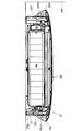
- FIG. 3 is a horizontal sectional view taken along line AA in FIG. 2.
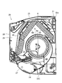
- FIG. 3 is a vertical sectional view cut along the line BB in FIG. 2.
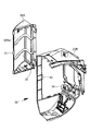
- FIG. 5 is a vertical sectional view similar to FIG. 4, showing a state of a louver different from FIG. 4. It is the same perspective view as FIG. 1, and shows the state which pushed up the opening / closing panel. It is a perspective view of the end member which constitutes a part of an indoor unit case, and the projection part attached to it.
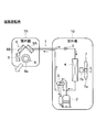
- FIGS. 11 and 12 show a basic configuration of a separate type air conditioner.
- the air conditioner depicted in FIGS. 11 and 12 uses the heat pump cycle 1 as the refrigeration cycle.
- the heat pump cycle 1 includes a compressor 2, a four-way valve 3, an outdoor heat exchanger 4, a decompression expansion device 5, and an indoor heat exchanger 6 connected in a loop.
- the compressor 2, the four-way valve 3, the outdoor heat exchanger 4, and the decompression / expansion device 5 are accommodated in a casing of the outdoor unit 10.
- the indoor heat exchanger 6 is accommodated in the housing of the indoor unit 20.
- the outdoor heat exchanger 4 functions as a condenser during cooling operation and functions as an evaporator during heating operation.
- the indoor heat exchanger 6 functions as an evaporator during cooling operation and functions as a condenser during heating operation.
- the outdoor heat exchanger 4 is combined with a blower 7 that forms an airflow passing therethrough.
- the blower 7 includes a fan 7a and a motor 7b that rotates the fan 7a.
- the fan 7a is a propeller fan.
- the indoor heat exchanger 6 is combined with a blower 8 that forms an airflow passing therethrough.
- the blower 8 includes a cross flow fan 8a arranged with its axis line horizontal and a motor (not shown) that rotates the fan.
- the indoor heat exchanger 6 is configured by combining three heat exchangers 6A, 6B, and 6C like a roof that covers the blower 8.
- the use of the three heat exchangers 6A, 6B, 6C for the indoor heat exchanger 6 is merely a configuration example, and any number of heat exchangers may be used.
- the configuration may be such that one heat exchanger is the indoor heat exchanger 6.
- FIG. 11 shows a state during cooling operation or defrosting operation.
- the high-temperature and high-pressure refrigerant discharged from the compressor 2 enters the outdoor heat exchanger 4 where it dissipates heat and condenses.
- the refrigerant that has exited the outdoor heat exchanger 4 enters the indoor heat exchanger 6 from the decompression / expansion device 5 and evaporates, takes heat from the indoor air, and returns to the compressor 2.
- the airflow generated by the blower 7 promotes heat dissipation from the outdoor heat exchanger 4, and the airflow generated by the blower 8 promotes heat absorption of the indoor heat exchanger 6.
- the air cooled by the indoor heat exchanger 6 blows out from a blower outlet (not shown) to lower the indoor temperature.
- Fig. 12 shows a state during heating.
- the four-way valve 3 is switched, and the refrigerant flow is reversed from that during the cooling operation. That is, the high-temperature and high-pressure refrigerant discharged from the compressor 2 enters the indoor heat exchanger 6 where it dissipates heat and condenses.
- the refrigerant that has exited the indoor heat exchanger 6 enters the outdoor heat exchanger 4 from the decompression / expansion device 5 and evaporates, takes in heat from the outdoor air, and returns to the compressor 2.
- the air flow generated by the blower 8 promotes heat radiation from the indoor heat exchanger 6, and the air flow generated by the blower 7 promotes heat absorption of the outdoor heat exchanger 4. Air warmed by the indoor heat exchanger 6 is blown out from a blower outlet (not shown) to raise the indoor temperature.
- the internal elements of the indoor unit 20 described above are accommodated in the indoor unit housing 20a shown in FIG.
- the indoor unit housing 20a is configured by combining a plurality of parts made of a synthetic resin injection molded product.
- the indoor unit 20 is installed above the wall surface of the room, and the indoor unit housing 20a is provided with various devices for realizing a comfortable air circulation for the user and improving the appearance. Yes. Hereinafter, this will be described with reference to FIGS.
- the indoor unit housing 20a is configured by combining a plurality of separate parts with a back member 21 serving as a base.
- the plurality of separate parts include an end member 22L that constitutes the left end of the indoor unit casing 20a, an end member 22R that constitutes the right end of the indoor unit casing 20a, and a space between the end members 22L and 22R.
- the air outlet member 22C combined with the lower front portion of the body 20a, the projecting portion 30L engaged with the end member 22L, the projecting portion 30R engaged with the end member 22R, the louver 27, and the front panel 28.
- the right end member 22R is provided with a display panel DP at the front lower portion.
- the display panel DP is provided with a display element and a display lamp for informing operation status, a light receiving window for receiving an infrared signal from a remote controller (not shown), and the like.
- an indoor heat exchanger 6 in which three heat exchangers 6A, 6B, and 6C are combined, and an indoor heat exchanger 6 are provided.
- a blower 8 that forms an airflow passing therethrough is disposed.
- the blower 8 is constituted by a cross flow fan 8a arranged with its axis line horizontal and a motor 8b (see FIG. 3) for rotating the fan.
- the rear member 21 has a suction port 23 formed on the top surface and an air outlet 24 formed on the lower front surface.
- the air outlet 24 is constituted by an air outlet member 22C.
- a ventilation path 25 is formed between the blower 8 and the outlet 24.
- a filter 26 is disposed on the windward side of the indoor heat exchanger 6.
- the filter 26 covers a region from the upper surface to the front surface of the indoor heat exchanger 6 and collects dust contained in the sucked indoor air.
- a louver 27 is arranged at the outlet 24.
- the louver 27 closes the outlet 24 as shown in FIGS. 1 and 4 when the operation of the indoor unit 20 is stopped.
- the louver 27 is moved as shown in FIG. 5 by a motor (not shown), and air is blown out from the outlet 24.
- the louver 27 may be stationary in an open state, or may swing to change the wind direction.
- the louver 27 When the indoor unit 20 is put into an operating state, the louver 27 is opened and the blower 8 is driven. In the cooling operation, the high-temperature and high-pressure refrigerant discharged from the compressor 2 is condensed in the outdoor heat exchanger 4, passes through the decompression / expansion device 5, and then enters the indoor heat exchanger 6 to evaporate. The surface of the inner heat exchanger 6 becomes a low temperature. For this reason, the air passing through the indoor heat exchanger 6 becomes cold air and blows out from the outlet 24.
- the high-temperature and high-pressure refrigerant discharged from the compressor 2 condenses in the indoor heat exchanger 6, so that the surface of the outdoor heat exchanger 6 becomes high temperature. For this reason, the air passing through the indoor heat exchanger 6 becomes warm air and blows out from the outlet 24.
- An opening / closing panel 28 that can move in the vertical direction is provided on the front surface of the rear member 21.
- the open / close panel 28 rotates about a fulcrum and takes two positions, a closed position shown in FIGS. 1 and 4 and an open position shown in FIG. 6.
- the opening 29 formed on the front surface of the back member 21 is opened, and the filter 26 is exposed.
- the filter 26 can be accessed. The user can take out the filter 26 and remove dust adhering thereto.
- the open / close panel 28 occupies the most important position among the design components of the indoor unit 20.
- the left-right width of the open / close panel 28 when viewed from the front is wider than the total width of the back member 21 and the end members 22L and 22R combined therewith.
- the left and right ends of the open / close panel 28 wrap around the left and right side surfaces of the indoor unit housing 20a and cover a part of the left and right side surfaces, as in the open / close panel of Patent Document 2. In this way, the size of the open / close panel 28 occupies most of the front shape of the indoor unit 20, and the left and right side surfaces of the indoor unit housing 20a are made inconspicuous, thereby improving the design.
- Projections 30L and 30R are formed on the left and right side surfaces of the indoor unit housing 20a at the same height as the open / close panel 28 in the closed state.
- the protruding heights of the protrusions 30L and 30R from the left and right side surfaces of the indoor unit housing 20a are set to be substantially the same as the protruding lengths of the left and right ends of the open / close panel 28 from the left and right side surfaces of the indoor unit housing 20a.
- the vertical widths of the protrusions 30L and 30R are set to be substantially the same as the vertical width of the open / close panel 28.
- the left and right ends of the open / close panel 28 are in close contact with the edges of the projecting portions 30L and 30R or approached to a grazing distance. That is, the protrusions 30L and 30R function as a structure that is continuous with the open / close panel 28 in the closed state.
- the projecting portions 30L and 30R are formed with slopes 30La and 30Ra that connect the end portions of the open / close panel 28 and the side surfaces of the end members 22L and 22R.
- the horizontal cross-sectional shapes of the protrusions 30L and 30R are substantially triangular as shown in FIG.
- the projecting portions 30L and 30R exist as structures that bridge the end portions of the open / close panel 28 and the side surfaces of the end members 22L and 22R, so that the open / close panel 28 was cut off suddenly at the end portions. The feeling is lost and the design is further improved.
- the protrusions 30L and 30R are configured as separate parts attached to the end members 22L and 22R.
- FIG. 7 shows a combination of the end member 22R and the protrusion 30R.
- the structure of the protrusion 30R can be easily understood with reference to the enlarged perspective view of FIG.
- the three claws 31 are formed on the edge of the projecting portion 30R facing the back side of the indoor unit 20 at intervals in the vertical direction.
- the end member 22 ⁇ / b> R is formed with an engagement hole 32 for engaging the claw 31 at a position corresponding to the claw 31.
- a protruding piece 33 is formed on the edge of the protruding portion 30R facing the front side of the indoor unit 20 at a position close to the upper end and a position close to the lower end.
- a through hole 34 is formed at a position corresponding to the protruding piece 33 in the end member 22R.
- FIG. 3 shows a state where the indoor unit 20 is installed close to the right wall surface WR. Between the right side surface of the indoor unit 20 and the wall surface WR, a distance equal to the protruding height of the protruding portion 30R from the right side surface is kept at a minimum. For this reason, the air blown out from the blower outlet 24 is sufficiently far away from the indoor unit 20 before hitting the wall surface WR and stalling. This reduces the occurrence of short circuits.
- the indoor unit 20 When the indoor unit 20 is placed on the floor of the room where the assembly line conveyor, work table, indoor unit 20 is mounted, etc., the protrusions protruded from the left and right side surfaces of the indoor unit housing 20a
- the indoor unit 20 can be easily lifted by placing a finger on the portions 30L and 30R.
- the handling of the indoor unit 20 is further facilitated by using the projecting portions 30L and 30R as the finger hanging portions. Since the projecting portions 30L and 30R are engaged with the claws 31 by the end members 22L and 22R and the projecting piece 33 is screwed to the projecting portions 30L and 30R, the projecting portions 30L and 30R will not come off even if a finger is put on them.
- the indoor unit 20 can be configured in many models with different sizes and designs by changing the combination of the end members 22L and 22R or the outlet member 22C combined with the back member 21. Since the protrusions 30L and 30R are separate parts, the variety of models can be increased by replacing the protrusions 30L and 30R.
- the height at which the protrusions 30L and 30R protrude from the left and right side surfaces of the indoor unit housing 20a does not necessarily have to be the same on the left and right. It is also possible to change the protruding height on the left and right, and to create an asymmetric design.
- the protrusions 30L and 30R are configured as separate members that engage with the end members 22L and 22R.
- the protrusions 30L and 30R may be integrally formed with the end members 22L and 22R without using the protrusions 30L and 30R as separate members. Good.
- FIG. 9 and FIG. 10 show a second embodiment of the present invention.
- the indoor air suction path is improved.
- FIG. 9 shows the protrusion 30R.
- a vent hole 36a and a vent hole 36b are formed in the slope 30Ra of the projecting portion 30R and the front face 30Rb facing the back face of the open / close panel 28.
- Each of the air holes 36a and 36b is composed of a plurality of slits.
- the air hole 36a communicates with the air hole 36b through the internal space of the protrusion 30R.
- the vent hole 36 b communicates with the windward space of the filter 26 from the back side of the open / close panel 28. That is, the vent hole 36 a communicates with the windward space of the filter 26 from the back side of the open / close panel 28.
- the protruding portion 30L side has the same structure.
- the space behind the open / close panel 28 becomes negative pressure.
- the room air is not only from the top suction port 23 of the back member 21 but also from the back side of the protrusions 30L and 30R through the air holes formed in the protrusions 30L and 30R as shown by the arrow S in FIG. Is also inhaled.
- the position of the opening part into which air is sucked in is dispersed, and the total area of the opening part is increased, whereby the ventilation resistance of the indoor unit 20 is reduced and the blowing efficiency is improved.
- the present invention is widely applicable to separate type air conditioners.
Landscapes
- Engineering & Computer Science (AREA)
- Chemical & Material Sciences (AREA)
- Combustion & Propulsion (AREA)
- Mechanical Engineering (AREA)
- General Engineering & Computer Science (AREA)
- Air Filters, Heat-Exchange Apparatuses, And Housings Of Air-Conditioning Units (AREA)
- Air-Conditioning Room Units, And Self-Contained Units In General (AREA)
Abstract
室内機(20)の室内機筐体(20a)は、背面部材(21)の左右両端に端部材(22L)(22R)を組み合わせて構成される。端部材には別部品の突出部(30L)(30R)が取り付けられる。突出部は、それが設けられている室内機の側面に対向する壁面と当該側面との距離を所定値以上に保つ働きをする。室内機筐体の前面には上下方向に動き得る開閉パネル(28)が設けられる。開閉パネルの左右両端は室内機筐体の左右側面に回り込み、突出部は開閉パネルに連続する構造部として機能する。
Description
本発明は空気調和機に関する。
家屋用の空気調和機は、室内機と室外機からなるセパレート型として構成されることが多い。特許文献1、2にセパレート型空気調和機の例を見ることができる。
空気調和機の室内機には、吹出口から吹き出された空気が室内を大きく循環することなく近道をして室内機に吸い込まれてしまうという、いわゆるショートサーキットの問題が生じることがある。ショートサーキットは、冷房時には冷却効率を低下させ、暖房時には暖房効率を低下させる。この問題に対処するため、特許文献1記載の室内機には次のような対策が施されている。
特許文献1記載の室内機は、通常は吹出口から下方に向け空気を送出するが、所定の時期になると吹出口から上方に向け空気を送出する。上方に空気を送出するのは、使用者に風を当て続けていると使用者が不快感を覚え、健康上の安全性も低下するためである。吹出口から上方に吹き出された空気は、何も対策が施されていなければ室内機上面の吸込口に直ちに吸い込まれ、ショートサーキットを生じてしまうが、当該室内機には、吹出口よりも上方の前面側を遮蔽する遮蔽部が設けられているので、ショートサーキットの発生を著しく低減することができる。
空気調和機の室内機には、前面側に開閉パネルが設置されているものがある。特許文献2記載の室内機のその一例である。特許文献2記載の室内機は、開閉パネルの左右方向の長さを室内機本体部の左右方向の長さよりも長く形成した上、開閉パネルの両端部を後面側に折り曲げ、この折り曲げ部が室内機本体部の側面の一部を覆っている。折り曲げ部と室内機本体部の間には側面吸込口が設けられている。この構成により、空気の吸込量を低下させることなく室内機の意匠性を高め、さらに、開閉パネルの剛性を高めている。
本発明は、セパレート型空気調和機の室内機において、ショートサーキットの発生を新規な技術的アプローチで低減させることを目的とする。
本発明の好ましい実施形態によれば、空気調和機は室内機と室外機からなり、前記室内機の左右側面のそれぞれに、当該室内機が設置される室の壁面の中で、当該側面に対向する壁面と当該側面との距離を所定値以上に保つ突出部が形成されている。
上記構成の空気調和機において、前記室内機の筐体には、左右両端に室内機筐体の一部を構成する端部材が組み合わせられ、前記端部材に前記突出部が形成されていることが好ましい。
上記構成の空気調和機において、前記端部材に取り付けられる別部品により前記突出部が形成されることが好ましい。
上記構成の空気調和機において、前記別部品の突出部は前記端部材に形成された貫通孔を通じて当該端部材の内部に侵入する突出片を備え、前記突出片が前記端部材にネジ止めされることにより前記別部品は前記端部材に固定されることが好ましい。
上記構成の空気調和機において、前記突出部は前記室内機を持ち上げる際の指掛け部として利用可能であることが好ましい。
上記構成の空気調和機において、前記室内機筐体の前面には上下方向に動き得る開閉パネルが設けられ、前記開閉パネルの左右両端は前記室内機筐体の左右側面に回り込み、前記突出部は前記開閉パネルに連続する構造部として機能することが好ましい。
上記構成の空気調和機において、前記開閉パネルを開放姿勢とすることにより、前記室内側熱交換器の風上側に配置されたフィルタへのアクセスが可能となることが好ましい。
上記構成の空気調和機において、前記突出部には、前記開閉パネルの裏側から前記フィルタの風上側空間に連通する通気孔が形成されていることが好ましい。
上記構成の空気調和機において、前記通気孔は、前記突出部の背面側の室内空間より空気を吸い込むためのものであることが好ましい。
通常の場合、室内機の吹出口にはルーバが設けられており、それはモータによって揺動し、送風方向を変化させる。室内機の側面が壁面に近づきすぎていると、吹出口から吹き出された空気が室内機から十分遠くまで離れる前に壁に当たってしまい、失速することがある。失速した空気は室内機に再び引き込まれ、ショートサーキットの原因となる。室内機の左右側面のそれぞれに形成された突出部が、当該側面に対向する壁面と当該側面との距離を所定値以上に保っていれば、吹出口から吹き出された空気は、壁に当たる前に室内機から十分遠くまで離れる。これにより、ショートサーキットの発生を低減することができる。
図11及び図12にはセパレート型空気調和機の基本的構成が示されている。図11及び図12に描かれた空気調和機は冷凍サイクルとしてヒートポンプサイクル1を用いる。ヒートポンプサイクル1は、圧縮機2、四方弁3、室外側熱交換器4、減圧膨張装置5、及び室内側熱交換器6をループ状に接続したものである。圧縮機2、四方弁3、室外側熱交換器4、及び減圧膨張装置5は室外機10の筐体に収容される。室内側熱交換器6は室内機20の筐体に収容される。
室外側熱交換器4は、冷房運転時には凝縮器として機能し、暖房運転時には蒸発器として機能する。室内側熱交換器6は、冷房運転時には蒸発器として機能し、暖房運転時には凝縮器として機能する。
室外側熱交換器4にはそれを通り抜ける気流を形成する送風機7が組み合わせられる。送風機7はファン7aとこれを回転させるモータ7bからなる。ファン7aはプロペラファンである。
室内側熱交換器6にはそれを通り抜ける気流を形成する送風機8が組み合わせられる。送風機8は、軸線を水平にして配置されたクロスフローファン8aと、それを回転させる図示しないモータにより構成される。室内側熱交換器6は、3個の熱交換器6A、6B、6Cを、送風機8を覆う屋根のように組み合わせて構成されている。なお室内側熱交換器6に3個の熱交換器6A、6B、6Cを用いたのは単なる構成例であり、何個の熱交換器を用いてもよい。1個の熱交換器を室内側熱交換器6とする構成であっても構わない。
図11は冷房運転時あるいは除霜運転時の状態を示す。この時は圧縮機2から吐出された高温高圧の冷媒が室外側熱交換器4に入ってそこで放熱し、凝縮する。室外側熱交換器4を出た冷媒は減圧膨張装置5から室内側熱交換器6に入って蒸発し、室内空気から熱を取り込んだ後、圧縮機2に戻る。送風機7によって生成された気流が室外側熱交換器4からの放熱を促進し、送風機8によって生成された気流が室内側熱交換器6の吸熱を促進する。室内側熱交換器6で冷却された空気が図示しない吹出口から吹き出し、室内温度を下げる。
図12は暖房時の状態を示す。この時は四方弁3が切り換えられて冷房運転時と冷媒の流れが逆になる。すなわち、圧縮機2から吐出された高温高圧の冷媒は室内側熱交換器6に入ってそこで放熱し、凝縮する。室内側熱交換器6を出た冷媒は減圧膨張装置5から室外側熱交換器4に入って蒸発し、室外空気から熱を取り込んだ後、圧縮機2に戻る。送風機8によって生成された気流が室内側熱交換器6からの放熱を促進し、送風機7によって生成された気流が室外側熱交換器4の吸熱を促進する。室内側熱交換器6で暖められた空気が図示しない吹出口から吹き出し、室内温度を上昇させる。
上述した室内機20の内部要素は、図1に示す室内機筐体20aに収容される。室内機筐体20aは合成樹脂射出成型品からなる複数の部品を組み合わせて構成される。室内機20は室内の壁面の上方に設置されるものであり、室内機筐体20aには、使用者にとり快適な空気循環を実現するため、また外観向上のため、様々な工夫が施されている。以下それを図1から図8までの図面に基づき説明する。
室内機筐体20aは、ベースとなる背面部材21に複数の別部品を組み合わせて構成される。複数の別部品とは、室内機筐体20aの左端を構成する端部材22L、室内機筐体20aの右端を構成する端部材22R、及び端部材22L、22Rの間を埋める形で室内機筐体20aの前面下部に組み合わせられる吹出口部材22C、端部材22Lに係合する突出部30L、端部材22Rに係合する突出部30R、ルーバ27、及び前面パネル28である。右側の端部材22Rには前面下部に表示パネルDPが設けられる。表示パネルDPには、運転状況を知らせる表示素子や表示ランプ、図示しないリモートコントローラからの赤外線信号を受光する受光窓などが配置されている。
背面部材21の内部には、図11及び図12に示した概略構成の通り、3個の熱交換器6A、6B、6Cを組み合わせた室内側熱交換器6と、室内側熱交換器6を通り抜ける気流を形成する送風機8が配置されている。送風機8は、軸線を水平にして配置されたクロスフローファン8aと、それを回転させるモータ8b(図3参照)により構成されている。
図4に示す通り、背面部材21には、天面に吸込口23、前面下部には吹出口24がそれぞれ形成されている。吹出口24は吹出口部材22Cにより構成される。送風機8と吹出口24の間には通風路25が形成されている。
室内側熱交換器6の風上側にはフィルタ26が配置される。フィルタ26は室内側熱交換器6の上面から前面にかけての領域を覆い、吸い込まれる室内空気に含まれる塵埃を捕集する。
吹出口24にはルーバ27が配置される。ルーバ27は、室内機20が運転停止中であるときは図1及び図4に示すように吹出口24を閉ざしている。室内機20の運転を開始すると、図示しないモータにより図5に示すようにルーバ27が動き、吹出口24から空気を吹き出させる。ルーバ27は、開いた状態で静止していることもあれば、揺動して風向に変化を与えることもある。
室内機20を運転状態にすると、ルーバ27が開き、送風機8が駆動される。冷房運転の場合は、圧縮機2から吐出された高温高圧の冷媒が室外側熱交換器4で凝縮され、減圧膨張装置5を通った後室内側熱交換器6に入って蒸発するので、室内側熱交換器6の表面は低温になる。このため、室内側熱交換器6を通る空気は冷気となって吹出口24から吹き出す。
暖房運転の場合は、圧縮機2から吐出された高温高圧の冷媒が室内側熱交換器6で凝縮するので、室外側熱交換器6の表面は高温になる。このため、室内側熱交換器6を通る空気は暖気となって吹出口24から吹き出す。
背面部材21の前面には上下方向に動き得る開閉パネル28が設けられる。開閉パネル28は支点を中心として回動するものであり、図1及び図4に示す閉鎖姿勢と、図6に示す開放姿勢の2姿勢をとる。開閉パネル28を押し上げて図6の開放姿勢にしたときは、背面部材21の前面に形成された開口部29が開放状態となり、フィルタ26が露出する。すなわちフィルタ26へのアクセスが可能となる。使用者はフィルタ26を取り出し、それに付着した塵埃を除去することができる。
開閉パネル28は、室内機20のデザイン構成要素の中で最も重要な地位を占める。開閉パネル28は正面から見たときの左右幅が背面部材21とそれに組み合わせられる端部材22L、22Rの合計幅よりも広くなっている。開閉パネル28の左右両端は、特許文献2の開閉パネルと同様、室内機筐体20aの左右側面に回り込んで左右側面の一部を覆う。このように開閉パネル28を室内機20の正面形状の大半を占める大きさとし、室内機筐体20aの左右側面を目立たなくすることにより、デザインを向上させている。
室内機筐体20aの左右側面には、閉鎖状態の開閉パネル28と同じ高さになるところに突出部30L、30Rが形成されている。突出部30L、30Rの室内機筐体20aの左右側面からの突出高さは、開閉パネル28の左右端の室内機筐体20aの左右側面からのはみ出し長さとほぼ同じに設定されている。突出部30L、30Rの上下方向の幅は開閉パネル28の上下方向の幅とほぼ同じに設定されている。開閉パネル28を閉鎖状態にしたとき、開閉パネル28の左右端は突出部30L、30Rの縁に密着するか、あるいはすれすれの距離まで接近する。すなわち突出部30L、30Rは、閉鎖状態の開閉パネル28に連続する構造体として機能する。
突出部30L、30Rには、開閉パネル28の端部と端部材22L、22Rの側面部をつなぐ斜面30La、30Raが形成されている。その結果、突出部30L、30Rの水平断面形状は図3に示す通り略三角形となる。このように、開閉パネル28の端部と端部材22L、22Rの側面部の間を橋渡しする構造物として突出部30L、30Rが存在することにより、開閉パネル28が端部で唐突に断ち切られた感じがなくなり、デザインがさらに向上する。
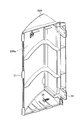
本実施形態では、突出部30L、30Rは、端部材22L、22Rに取り付けられる別部品として構成されている。図7に示すのは端部材22Rと突出部30Rの組み合わせである。突出部30Rの構造は、図8の拡大斜視図を参照するとわかりやすい。
室内機20の背面側を向いた突出部30Rの縁には、上下方向に間隔を置いて3個の爪31が形成されている。端部材22Rには、爪31に対応する位置に、爪31を係合させる係合孔32が形成されている。
室内機20の前面側を向いた突出部30Rの縁には、上端に近い箇所と下端に近い箇所に突出片33が形成されている。端部材22Rには突出片33に対応する位置に貫通孔34が形成されている。係合孔32に係合した爪31を支点として突出部30Rを端部材22Rの方に回動させると、突出片33が貫通孔34から端部材22Rの内部に侵入する。端部材22Rの内部に侵入した突出片33をネジ35で端部材22Rにネジ止めすることにより、突出部30Rは端部材22Rに強固に固定される。突出部30Lと端部材22Lの組み合わせも、突出部30Rと端部材22Rの組み合わせと同様の手法で固定される。
突出部30L、30Rが存在するため、室内機筐体20aの左右側面をそれに対向する壁面にあまり近づけることができない。図3には室内機20を右側の壁面WRの方に寄せて設置した状態が示されている。室内機20の右側面と壁面WRの間には、右側面からの突出部30Rの突出高さに等しい距離が最低限保たれる。このため、吹出口24から吹き出された空気は、壁面WRに当たって失速する前に室内機20から十分遠くまで離れる。これにより、ショートサーキットの発生が低減する。
組立ラインのコンベア、作業台、室内機20が取り付けられる部屋の床の上などに、室内機20が背面側を下にして置かれている場合、室内機筐体20aの左右側面から突き出した突出部30L、30Rに指を掛ければ室内機20を容易に持ち上げることができる。このように、突出部30L、30Rを指掛け部として利用することにより、室内機20の取り扱いが一層容易になる。突出部30L、30Rは端部材22L、22Rに爪31を係合した上で突出片33をネジ止めされているため、それに指を掛けたとしても外れるようなことはない。
室内機20は、背面部材21に組み合わせられる端部材22L、22Rあるいは吹出口部材22Cの取り合わせを変えることにより、サイズやデザインが異なる多くの機種を構成できる。突出部30L、30Rが別部品であるため、突出部30L、30Rを取り替えることによっても機種のバラエティを増やすことができる。
室内機筐体20aの左右側面から突出部30L、30Rが突出する高さは、必ずしも左右同一でなければならない訳ではない。左右で突出高さを変え、左右非対称のデザインとしてもよい。
本実施形態では、突出部30L、30Rを、端部材22L、22Rに係合する別部材として構成したが、突出部30L、30Rを別部材としないで端部材22L、22Rに一体成型してもよい。
本発明の第2実施形態を図9及び図10に示す。第2実施形態は、室内空気の吸込経路の改善を図ったものである。
図9には突出部30Rが示されている。突出部30Rの斜面30Raと、開閉パネル28の裏面に対向する前面30Rbには、通気孔36aと通気孔36bが形成されている。通気孔36a、36bはいずれも複数のスリットの集合からなる。通気孔36aは突出部30Rの内部空間を通じて通気孔36bに連通する。通気孔36bは開閉パネル28の裏側からフィルタ26の風上側空間に連通する。すなわち、通気孔36aは開閉パネル28の裏側からフィルタ26の風上側空間に連通することになる。突出部30Lの側も同様の構造になっている。
送風機8を運転すると開閉パネル28の裏側の空間が負圧になる。室内空気は、背面部材21の天面の吸込口23のみならず、図10に矢印Sで示す通り、突出部30L、30Rにそれぞれ形成された通気孔を通じて、突出部30L、30Rの背面側からも吸い込まれる。このように空気が吸い込まれる開口部の位置が分散し、開口部の合計面積が増大することにより、室内機20の通風抵抗が減少し、送風効率が向上する。また、吸込箇所の風速が低下するので、室内機20から発生する騒音を低下させることができる。
以上、本発明の実施形態につき説明したが、本発明の範囲はこれに限定されるものではなく、発明の主旨を逸脱しない範囲で種々の変更を加えて実施することができる。
本発明はセパレート型空気調和機に広く利用可能である。
1 冷凍サイクル
2 圧縮機
4 室外側熱交換器
6 室内側熱交換器
7、8 送風機
10 室外機
20 室内機
20a 室内機筐体
21 背面部材
22L、22R 端部材
22C 吹出口部材
23 吸込口
24 吹出口
26 フィルタ
27 ルーバ
28 開閉パネル
30L、30R 突出部
31 爪
32 係合孔
33 突出片
34 貫通孔
35 ネジ
36a、36b 通気孔
DP 表示パネル
2 圧縮機
4 室外側熱交換器
6 室内側熱交換器
7、8 送風機
10 室外機
20 室内機
20a 室内機筐体
21 背面部材
22L、22R 端部材
22C 吹出口部材
23 吸込口
24 吹出口
26 フィルタ
27 ルーバ
28 開閉パネル
30L、30R 突出部
31 爪
32 係合孔
33 突出片
34 貫通孔
35 ネジ
36a、36b 通気孔
DP 表示パネル
Claims (9)
- 空気調和機であって、以下の構成を備えるもの:
室外機と室内機を備え、
前記室内機の左右側面のそれぞれに、当該室内機が設置される室の壁面の中で、当該側面に対向する壁面と当該側面との距離を所定値以上に保つ突出部が形成されている。 - 請求項1の空気調和機であって、以下の構成を備えるもの:
前記室内機の筐体には、左右両端に当該室内機筐体の一部を構成する端部材が組み合わせられ、
前記端部材に前記突出部が形成される。 - 請求項2の空気調和機であって、以下の構成を備えるもの:
前記端部材に取り付けられる別部品により前記突出部が形成される。 - 請求項3の空気調和機であって、以下の構成を備えるもの:
前記別部品の突出部は前記端部材に形成された貫通孔を通じて当該端部材の内部に侵入する突出片を備え、
前記突出片が前記端部材にネジ止めされることにより前記別部品は前記端部材に固定される。 - 請求項1の空気調和機であって、以下の構成を備えるもの:
前記突出部は前記室内機を持ち上げる際の指掛け部として利用可能である。 - 請求項1の空気調和機であって、以下の構成を備えるもの:
前記室内機筐体の前面には上下方向に動き得る開閉パネルが設けられ、
前記開閉パネルの左右両端は前記室内機筐体の左右側面に回り込み、
前記突出部は前記開閉パネルに連続する構造部として機能する。 - 請求項6の空気調和機であって、以下の構成を備えるもの:
前記開閉パネルを開放姿勢とすることにより、前記室内側熱交換器の風上側に配置されたフィルタへのアクセスが可能となる。 - 請求項7の空気調和機であって、以下の構成を備えるもの:
前記突出部には、前記開閉パネルの裏側から前記フィルタの風上側空間に連通する通気孔が形成されている。 - 請求項8の空気調和機であって、以下の構成を備えるもの:
前記通気孔は、前記突出部の背面側の室内空間より空気を吸い込むためのものである。
Applications Claiming Priority (2)
| Application Number | Priority Date | Filing Date | Title |
|---|---|---|---|
| JP2011038812A JP2012172959A (ja) | 2011-02-24 | 2011-02-24 | 空気調和機 |
| JP2011-038812 | 2011-02-24 |
Publications (1)
| Publication Number | Publication Date |
|---|---|
| WO2012114841A1 true WO2012114841A1 (ja) | 2012-08-30 |
Family
ID=46720629
Family Applications (1)
| Application Number | Title | Priority Date | Filing Date |
|---|---|---|---|
| PCT/JP2012/052333 Ceased WO2012114841A1 (ja) | 2011-02-24 | 2012-02-02 | 空気調和機 |
Country Status (2)
| Country | Link |
|---|---|
| JP (1) | JP2012172959A (ja) |
| WO (1) | WO2012114841A1 (ja) |
Cited By (1)
| Publication number | Priority date | Publication date | Assignee | Title |
|---|---|---|---|---|
| EP3076096A4 (en) * | 2013-11-26 | 2017-02-01 | Daikin Industries, Ltd. | Indoor unit |
Citations (14)
| Publication number | Priority date | Publication date | Assignee | Title |
|---|---|---|---|---|
| JPS56109520U (ja) * | 1980-01-25 | 1981-08-25 | ||
| JPS5775322U (ja) * | 1980-10-24 | 1982-05-10 | ||
| JPS61502326A (ja) * | 1984-06-07 | 1986-10-16 | コウ、トマス・ユ− | 基板媒体キャリヤ |
| JPS6245409U (ja) * | 1985-09-06 | 1987-03-19 | ||
| JPH06221610A (ja) * | 1993-01-28 | 1994-08-12 | Sanyo Electric Co Ltd | 空気調和機 |
| JPH0894117A (ja) * | 1994-09-26 | 1996-04-12 | Daikin Ind Ltd | 天吊式空気調和機のケーシング構造 |
| WO2002103251A2 (en) * | 2001-06-19 | 2002-12-27 | Lg Electronics Inc. | Air conditioner |
| JP2004163077A (ja) * | 2002-11-11 | 2004-06-10 | Samsung Electronics Co Ltd | 空気調和機 |
| JP2004337794A (ja) * | 2003-05-19 | 2004-12-02 | Okuma Corp | ろ過装置 |
| JP2005283069A (ja) * | 2004-03-31 | 2005-10-13 | Fujitsu General Ltd | 空気調和機 |
| JP2006340336A (ja) * | 2005-06-02 | 2006-12-14 | Sharp Corp | 表示装置 |
| JP2010151333A (ja) * | 2008-12-24 | 2010-07-08 | Toshiba Carrier Corp | 空気調和機の室内機 |
| JP2010196976A (ja) * | 2009-02-25 | 2010-09-09 | Sanyo Electric Co Ltd | 農事用空気調和装置 |
| JP2011021878A (ja) * | 2010-10-15 | 2011-02-03 | Daikin Industries Ltd | 空気調和機 |
Family Cites Families (3)
| Publication number | Priority date | Publication date | Assignee | Title |
|---|---|---|---|---|
| JP3175197B2 (ja) * | 1991-07-10 | 2001-06-11 | 松下電器産業株式会社 | 機器のフロントパネル取付装置 |
| JP3121505B2 (ja) * | 1994-11-02 | 2001-01-09 | 三菱電機株式会社 | 空気調和機 |
| JP4924696B2 (ja) * | 2009-11-04 | 2012-04-25 | ダイキン工業株式会社 | 壁掛け型室内機 |
-
2011
- 2011-02-24 JP JP2011038812A patent/JP2012172959A/ja not_active Ceased
-
2012
- 2012-02-02 WO PCT/JP2012/052333 patent/WO2012114841A1/ja not_active Ceased
Patent Citations (14)
| Publication number | Priority date | Publication date | Assignee | Title |
|---|---|---|---|---|
| JPS56109520U (ja) * | 1980-01-25 | 1981-08-25 | ||
| JPS5775322U (ja) * | 1980-10-24 | 1982-05-10 | ||
| JPS61502326A (ja) * | 1984-06-07 | 1986-10-16 | コウ、トマス・ユ− | 基板媒体キャリヤ |
| JPS6245409U (ja) * | 1985-09-06 | 1987-03-19 | ||
| JPH06221610A (ja) * | 1993-01-28 | 1994-08-12 | Sanyo Electric Co Ltd | 空気調和機 |
| JPH0894117A (ja) * | 1994-09-26 | 1996-04-12 | Daikin Ind Ltd | 天吊式空気調和機のケーシング構造 |
| WO2002103251A2 (en) * | 2001-06-19 | 2002-12-27 | Lg Electronics Inc. | Air conditioner |
| JP2004163077A (ja) * | 2002-11-11 | 2004-06-10 | Samsung Electronics Co Ltd | 空気調和機 |
| JP2004337794A (ja) * | 2003-05-19 | 2004-12-02 | Okuma Corp | ろ過装置 |
| JP2005283069A (ja) * | 2004-03-31 | 2005-10-13 | Fujitsu General Ltd | 空気調和機 |
| JP2006340336A (ja) * | 2005-06-02 | 2006-12-14 | Sharp Corp | 表示装置 |
| JP2010151333A (ja) * | 2008-12-24 | 2010-07-08 | Toshiba Carrier Corp | 空気調和機の室内機 |
| JP2010196976A (ja) * | 2009-02-25 | 2010-09-09 | Sanyo Electric Co Ltd | 農事用空気調和装置 |
| JP2011021878A (ja) * | 2010-10-15 | 2011-02-03 | Daikin Industries Ltd | 空気調和機 |
Cited By (2)
| Publication number | Priority date | Publication date | Assignee | Title |
|---|---|---|---|---|
| EP3076096A4 (en) * | 2013-11-26 | 2017-02-01 | Daikin Industries, Ltd. | Indoor unit |
| AU2014355764B2 (en) * | 2013-11-26 | 2017-10-26 | Daikin Industries, Ltd. | Indoor unit |
Also Published As
| Publication number | Publication date |
|---|---|
| JP2012172959A (ja) | 2012-09-10 |
Similar Documents
| Publication | Publication Date | Title |
|---|---|---|
| KR101640411B1 (ko) | 공기조화기 | |
| WO2013108658A1 (ja) | 空気調和機 | |
| WO2014178166A1 (ja) | 化粧パネル及びそれを備えた空気調和機の室内ユニット | |
| JP2007192480A (ja) | 空気調和機 | |
| KR20050022680A (ko) | 에어컨 실내기 | |
| JP6942082B2 (ja) | 一体型空気調和機 | |
| JP6075088B2 (ja) | 空気調和機 | |
| WO2012114841A1 (ja) | 空気調和機 | |
| JP5773674B2 (ja) | 空気調和機の室内機 | |
| JP2015218993A (ja) | 空気調和機 | |
| JP4708199B2 (ja) | 空気調和機 | |
| JP5803974B2 (ja) | 化粧パネル及びそれを備えた空気調和機の室内ユニット | |
| JP2013127363A (ja) | 空気調和機 | |
| JP6081955B2 (ja) | 空気調和機 | |
| KR100412408B1 (ko) | 공기흡입커버를 구비한 패키지 에어컨 실내기 | |
| KR101328531B1 (ko) | 에어컨 및 냉동장치용 실외기의 전면커버 | |
| JP2012042208A (ja) | 空気調和機 | |
| CN1766431B (zh) | 空调机 | |
| KR101086612B1 (ko) | 공기 조화기 실내기의 토출구 개폐구조 | |
| KR100613513B1 (ko) | 일체형 공기조화기 | |
| KR100750233B1 (ko) | 패키지 에어컨의 디스플레이용 인쇄회로기판 체결구조 | |
| KR100412415B1 (ko) | 에어컨의 흡입구조 | |
| KR200312147Y1 (ko) | 룸 에어컨의 구조 | |
| JP2019066147A (ja) | 床置型空気調和機 | |
| CN1959226A (zh) | 柜式空调器室内机 |
Legal Events
| Date | Code | Title | Description |
|---|---|---|---|
| 121 | Ep: the epo has been informed by wipo that ep was designated in this application |
Ref document number: 12749962 Country of ref document: EP Kind code of ref document: A1 |
|
| NENP | Non-entry into the national phase |
Ref country code: DE |
|
| 122 | Ep: pct application non-entry in european phase |
Ref document number: 12749962 Country of ref document: EP Kind code of ref document: A1 |