WO2012114826A1 - Junction device, junction system and junction method - Google Patents
Junction device, junction system and junction method Download PDFInfo
- Publication number
- WO2012114826A1 WO2012114826A1 PCT/JP2012/051821 JP2012051821W WO2012114826A1 WO 2012114826 A1 WO2012114826 A1 WO 2012114826A1 JP 2012051821 W JP2012051821 W JP 2012051821W WO 2012114826 A1 WO2012114826 A1 WO 2012114826A1
- Authority
- WO
- WIPO (PCT)
- Prior art keywords
- substrate
- wafer
- holding member
- central portion
- bonding
- Prior art date
Links
Images


Classifications
-
- H—ELECTRICITY
- H01—ELECTRIC ELEMENTS
- H01L—SEMICONDUCTOR DEVICES NOT COVERED BY CLASS H10
- H01L21/00—Processes or apparatus adapted for the manufacture or treatment of semiconductor or solid state devices or of parts thereof
- H01L21/67—Apparatus specially adapted for handling semiconductor or electric solid state devices during manufacture or treatment thereof; Apparatus specially adapted for handling wafers during manufacture or treatment of semiconductor or electric solid state devices or components ; Apparatus not specifically provided for elsewhere
- H01L21/67005—Apparatus not specifically provided for elsewhere
- H01L21/67011—Apparatus for manufacture or treatment
- H01L21/67092—Apparatus for mechanical treatment
-
- H—ELECTRICITY
- H01—ELECTRIC ELEMENTS
- H01L—SEMICONDUCTOR DEVICES NOT COVERED BY CLASS H10
- H01L21/00—Processes or apparatus adapted for the manufacture or treatment of semiconductor or solid state devices or of parts thereof
- H01L21/67—Apparatus specially adapted for handling semiconductor or electric solid state devices during manufacture or treatment thereof; Apparatus specially adapted for handling wafers during manufacture or treatment of semiconductor or electric solid state devices or components ; Apparatus not specifically provided for elsewhere
- H01L21/67005—Apparatus not specifically provided for elsewhere
- H01L21/67011—Apparatus for manufacture or treatment
- H01L21/6715—Apparatus for applying a liquid, a resin, an ink or the like
-
- H—ELECTRICITY
- H01—ELECTRIC ELEMENTS
- H01L—SEMICONDUCTOR DEVICES NOT COVERED BY CLASS H10
- H01L21/00—Processes or apparatus adapted for the manufacture or treatment of semiconductor or solid state devices or of parts thereof
- H01L21/67—Apparatus specially adapted for handling semiconductor or electric solid state devices during manufacture or treatment thereof; Apparatus specially adapted for handling wafers during manufacture or treatment of semiconductor or electric solid state devices or components ; Apparatus not specifically provided for elsewhere
- H01L21/677—Apparatus specially adapted for handling semiconductor or electric solid state devices during manufacture or treatment thereof; Apparatus specially adapted for handling wafers during manufacture or treatment of semiconductor or electric solid state devices or components ; Apparatus not specifically provided for elsewhere for conveying, e.g. between different workstations
- H01L21/67739—Apparatus specially adapted for handling semiconductor or electric solid state devices during manufacture or treatment thereof; Apparatus specially adapted for handling wafers during manufacture or treatment of semiconductor or electric solid state devices or components ; Apparatus not specifically provided for elsewhere for conveying, e.g. between different workstations into and out of processing chamber
- H01L21/67748—Apparatus specially adapted for handling semiconductor or electric solid state devices during manufacture or treatment thereof; Apparatus specially adapted for handling wafers during manufacture or treatment of semiconductor or electric solid state devices or components ; Apparatus not specifically provided for elsewhere for conveying, e.g. between different workstations into and out of processing chamber horizontal transfer of a single workpiece
-
- H—ELECTRICITY
- H01—ELECTRIC ELEMENTS
- H01L—SEMICONDUCTOR DEVICES NOT COVERED BY CLASS H10
- H01L21/00—Processes or apparatus adapted for the manufacture or treatment of semiconductor or solid state devices or of parts thereof
- H01L21/67—Apparatus specially adapted for handling semiconductor or electric solid state devices during manufacture or treatment thereof; Apparatus specially adapted for handling wafers during manufacture or treatment of semiconductor or electric solid state devices or components ; Apparatus not specifically provided for elsewhere
- H01L21/68—Apparatus specially adapted for handling semiconductor or electric solid state devices during manufacture or treatment thereof; Apparatus specially adapted for handling wafers during manufacture or treatment of semiconductor or electric solid state devices or components ; Apparatus not specifically provided for elsewhere for positioning, orientation or alignment
- H01L21/681—Apparatus specially adapted for handling semiconductor or electric solid state devices during manufacture or treatment thereof; Apparatus specially adapted for handling wafers during manufacture or treatment of semiconductor or electric solid state devices or components ; Apparatus not specifically provided for elsewhere for positioning, orientation or alignment using optical controlling means
-
- H—ELECTRICITY
- H01—ELECTRIC ELEMENTS
- H01L—SEMICONDUCTOR DEVICES NOT COVERED BY CLASS H10
- H01L21/00—Processes or apparatus adapted for the manufacture or treatment of semiconductor or solid state devices or of parts thereof
- H01L21/67—Apparatus specially adapted for handling semiconductor or electric solid state devices during manufacture or treatment thereof; Apparatus specially adapted for handling wafers during manufacture or treatment of semiconductor or electric solid state devices or components ; Apparatus not specifically provided for elsewhere
- H01L21/683—Apparatus specially adapted for handling semiconductor or electric solid state devices during manufacture or treatment thereof; Apparatus specially adapted for handling wafers during manufacture or treatment of semiconductor or electric solid state devices or components ; Apparatus not specifically provided for elsewhere for supporting or gripping
- H01L21/6838—Apparatus specially adapted for handling semiconductor or electric solid state devices during manufacture or treatment thereof; Apparatus specially adapted for handling wafers during manufacture or treatment of semiconductor or electric solid state devices or components ; Apparatus not specifically provided for elsewhere for supporting or gripping with gripping and holding devices using a vacuum; Bernoulli devices
-
- H—ELECTRICITY
- H01—ELECTRIC ELEMENTS
- H01L—SEMICONDUCTOR DEVICES NOT COVERED BY CLASS H10
- H01L21/00—Processes or apparatus adapted for the manufacture or treatment of semiconductor or solid state devices or of parts thereof
- H01L21/67—Apparatus specially adapted for handling semiconductor or electric solid state devices during manufacture or treatment thereof; Apparatus specially adapted for handling wafers during manufacture or treatment of semiconductor or electric solid state devices or components ; Apparatus not specifically provided for elsewhere
- H01L21/683—Apparatus specially adapted for handling semiconductor or electric solid state devices during manufacture or treatment thereof; Apparatus specially adapted for handling wafers during manufacture or treatment of semiconductor or electric solid state devices or components ; Apparatus not specifically provided for elsewhere for supporting or gripping
- H01L21/687—Apparatus specially adapted for handling semiconductor or electric solid state devices during manufacture or treatment thereof; Apparatus specially adapted for handling wafers during manufacture or treatment of semiconductor or electric solid state devices or components ; Apparatus not specifically provided for elsewhere for supporting or gripping using mechanical means, e.g. chucks, clamps or pinches
- H01L21/68714—Apparatus specially adapted for handling semiconductor or electric solid state devices during manufacture or treatment thereof; Apparatus specially adapted for handling wafers during manufacture or treatment of semiconductor or electric solid state devices or components ; Apparatus not specifically provided for elsewhere for supporting or gripping using mechanical means, e.g. chucks, clamps or pinches the wafers being placed on a susceptor, stage or support
- H01L21/68742—Apparatus specially adapted for handling semiconductor or electric solid state devices during manufacture or treatment thereof; Apparatus specially adapted for handling wafers during manufacture or treatment of semiconductor or electric solid state devices or components ; Apparatus not specifically provided for elsewhere for supporting or gripping using mechanical means, e.g. chucks, clamps or pinches the wafers being placed on a susceptor, stage or support characterised by a lifting arrangement, e.g. lift pins
Definitions
- the present invention relates to a bonding apparatus, a bonding system, and a bonding method for bonding substrates together.
- the bonding apparatus includes a chamber that accommodates two wafers arranged vertically (hereinafter, the upper wafer is referred to as an “upper wafer” and the lower wafer is referred to as a “lower wafer”), And a push pin that presses the center portion of the upper wafer, and a spacer that supports the outer periphery of the upper wafer and can be retracted from the outer periphery of the upper wafer.
- the wafers are bonded to each other in a vacuum atmosphere in order to suppress the generation of voids between the wafers. Specifically, first, in a state where the upper wafer is supported by the spacer, the central portion of the upper wafer is pressed by the push pin, and the central portion is brought into contact with the lower wafer. Thereafter, the spacer supporting the upper wafer is retracted, and the entire surface of the upper wafer is brought into contact with the entire surface of the lower wafer and bonded together (Patent Document 1).
- the present invention has been made in view of such a point, and an object thereof is to appropriately and efficiently bond substrates together while suppressing the generation of voids between the substrates.
- the present invention is a bonding apparatus for bonding substrates to each other, and is provided below the first holding member, a first holding member that sucks and holds the first substrate on the lower surface. And a second holding member for placing and holding the second substrate on the upper surface, and a pushing member provided on the first holding member and pressing the central portion of the first substrate.
- the first holding member is partitioned into a plurality of regions from the central portion toward the outer peripheral portion, and evacuation of the first substrate can be set for each region.
- first substrate is sequentially brought into contact with the second substrate from the center portion of the first substrate toward the outer peripheral portion, for example, a void can be formed between the first substrate and the second substrate.
- air is always present on the outer peripheral side from the portion where the first substrate is in contact with the second substrate. If it does so, the said air can be escaped from a center part to an outer peripheral part between board
- the present invention it is not necessary to use a vacuum atmosphere when bonding the substrates as in the prior art, so that the substrates can be bonded efficiently in a short time, and the throughput of the substrate bonding process is improved. Can be made.
- Another aspect of the present invention is a bonding system including the bonding apparatus, wherein a processing station including the bonding apparatus, a first substrate, a second substrate, or a first substrate and a second substrate are provided. A plurality of bonded superposed substrates can be held, and a loading / unloading station for loading / unloading the first substrate, the second substrate or the superposed substrate with respect to the processing station is provided.
- the processing station includes a surface activation device that activates a surface to be bonded of the first substrate or the second substrate, and a surface of the first substrate or the second substrate activated by the surface activation device.
- a surface hydrophilizing device that hydrophilizes, a transport region for transporting the first substrate, the second substrate, or the polymerization substrate to the surface activating device, the surface hydrophilizing device, and the bonding device; have.
- the first substrate and the second substrate whose surfaces are hydrophilized by the surface hydrophilizing apparatus are bonded.
- a bonding method for bonding substrates using a bonding apparatus wherein the bonding apparatus includes a first holding member that holds the first substrate by suction on the lower surface, and the first holding member.
- a second holding member provided on the upper surface for holding and holding the second substrate, and a pressing member provided on the first holding member for pressing the central portion of the first substrate.
- a moving member The first holding member is partitioned into a plurality of regions from the central portion toward the outer peripheral portion, and evacuation of the first substrate can be set for each region, and the bonding method includes the first holding member.
- the first substrate is sequentially brought into contact with the second substrate toward the substrate, and the first substrate and the second substrate are bonded together. It has a bonding step that, a.
- the present invention it is possible to appropriately and efficiently bond the substrates together while suppressing the generation of voids between the substrates.
- FIG. 1 is a plan view showing the outline of the configuration of the joining system 1 according to the present embodiment.
- FIG. 2 is a side view illustrating the outline of the internal configuration of the joining system 1.
- the wafer disposed on the upper side is referred to as “upper wafer W U ” as the first substrate
- the wafer disposed on the lower side is referred to as “lower wafer W L ” as the second substrate.
- a bonding surface to which the upper wafer W U is bonded is referred to as “front surface W U1 ”
- a surface opposite to the front surface W U1 is referred to as “back surface W U2 ”.
- the bonding surface to which the lower wafer W L is bonded is referred to as “front surface W L1 ”, and the surface opposite to the front surface W L1 is referred to as “back surface WL 2 ”. Then, in the bonding system 1, by joining the upper wafer W U and the lower wafer W L, to form the overlapped wafer W T as a polymerization substrate.
- the bonding system 1 carries in and out cassettes C U , C L , and C T that can accommodate a plurality of wafers W U and W L and a plurality of superposed wafers W T , respectively, with the outside.
- the loading / unloading station 2 and the processing station 3 including various processing apparatuses that perform predetermined processing on the wafers W U , W L , and the overlapped wafer W T are integrally connected.
- the loading / unloading station 2 is provided with a cassette mounting table 10.
- the cassette mounting table 10 is provided with a plurality of, for example, four cassette mounting plates 11.
- the cassette mounting plates 11 are arranged in a line in the horizontal X direction (vertical direction in FIG. 1). These cassette mounting plates 11, cassettes C U to the outside of the interface system 1, C L, when loading and unloading the C T, a cassette C U, C L, it is possible to place the C T .
- carry-out station 2 a wafer over multiple W U, a plurality of lower wafer W L, and is configured to be held by a plurality of overlapped wafer W T.
- the number of cassette mounting plates 11 is not limited to the present embodiment, and can be arbitrarily determined.
- One of the cassettes may be used for collecting abnormal wafers. That is a cassette a wafer abnormality occurs in the bonding of the upper wafer W U and the lower wafer W L, it can be separated from the other normal overlapped wafer W T by various factors. In the present embodiment, among the plurality of cassettes C T, using a one cassette C T for the recovery of the abnormal wafer, and using other cassettes C T for the accommodation of a normal overlapped wafer W T.
- a wafer transfer unit 20 is provided adjacent to the cassette mounting table 10.
- the wafer transfer unit 20 is provided with a wafer transfer device 22 that is movable on a transfer path 21 extending in the X direction.
- the wafer transfer device 22 is also movable in the vertical direction and around the vertical axis ( ⁇ direction), and includes cassettes C U , C L , C T on each cassette mounting plate 11 and a third of the processing station 3 described later.
- the wafers W U and W L and the superposed wafer W T can be transferred between the transition devices 50 and 51 in the processing block G3.
- the processing station 3 is provided with a plurality of, for example, three processing blocks G1, G2, G3 provided with various devices.
- a first processing block G1 is provided on the front side of the processing station 3 (X direction negative direction side in FIG. 1), and on the back side of the processing station 3 (X direction positive direction side in FIG. 1)
- Two processing blocks G2 are provided.
- a third processing block G3 is provided on the loading / unloading station 2 side of the processing station 3 (Y direction negative direction side in FIG. 1).
- a surface activation device 30 that activates the surfaces W U1 and W L1 of the wafers W U and W L is arranged.
- the second processing block G2 includes, for example, a surface hydrophilizing device 40 that hydrophilizes the surfaces W U1 and W L1 of the wafers W U and W L with pure water and cleans the surfaces W U1 and W L1.
- a surface hydrophilizing device 40 that hydrophilizes the surfaces W U1 and W L1 of the wafers W U and W L with pure water and cleans the surfaces W U1 and W L1.
- U, bonding device 41 for bonding the W L are arranged side by side in the horizontal direction of the Y-direction in this order from the carry-out station 2 side.
- the third processing block G3, the wafer W U as shown in FIG. 2, W L, a transition unit 50, 51 of the overlapped wafer W T are provided in two tiers from the bottom in order.
- a wafer transfer region 60 is formed in a region surrounded by the first processing block G1 to the third processing block G3.
- a wafer transfer device 61 is disposed in the wafer transfer region 60.
- the wafer transfer device 61 has, for example, a transfer arm that can move around the vertical direction, horizontal direction (Y direction, X direction), and vertical axis.
- the wafer transfer device 61 moves in the wafer transfer region 60, and adds wafers W U , W L , and W to predetermined devices in the surrounding first processing block G1, second processing block G2, and third processing block G3. You can transfer the overlapping wafer W T.
- the surface activation device 30 has a processing container 70 capable of sealing the inside.
- a lower electrode 80 for placing the wafers W U and W L is provided inside the processing container 70.
- the lower electrode 80 is made of a conductive material such as aluminum.
- a drive unit 81 including a motor or the like is provided below the lower electrode 80. The lower electrode 80 can be moved up and down by the drive unit 81.
- a heat medium circulation channel 82 is provided inside the lower electrode 80.
- a heat medium whose temperature is adjusted to an appropriate temperature by a temperature adjusting means (not shown) is introduced into the heat medium circulation passage 82 via a heat medium introduction pipe 83.
- the heat medium introduced from the heat medium introduction pipe 83 circulates in the heat medium circulation channel 82, whereby the lower electrode 80 is adjusted to a desired temperature.
- the heat of the lower electrode 80, the wafer W U which is placed on the upper surface of the lower electrode 80, is transmitted to the W L, the wafer W U, W L is adjusted to a desired temperature.
- the temperature adjustment mechanism for adjusting the temperature of the lower electrode 80 is not limited to the heat medium circulation passage 82, and other mechanisms such as a cooling jacket and a heater can also be used.
- the upper part of the lower electrode 80 is configured as an electrostatic chuck 90 for electrostatically attracting the wafers W U and W L.
- the electrostatic chuck 90 has a structure in which a conductive film 93 such as a copper foil is disposed between two films 91 and 92 made of a polymer insulating material such as polyimide resin.
- the conductive film 93 is connected to a high-voltage power source 96 through a wiring 94 and a filter 95 such as a coil.
- a high voltage set to an arbitrary DC voltage is cut from the high voltage power source 96 by the filter 95 and applied to the conductive film 93.
- W L is brought into electrostatic attraction.
- the upper surface of the lower electrode 80, the wafer W U, a plurality of heat transfer gas supply holes 100 for supplying a heat transfer gas toward the rear surface of the W L is provided. As shown in FIG. 5, the plurality of heat transfer gas supply holes 100 are uniformly arranged in a plurality of concentric circles on the upper surface of the lower electrode 80.
- a heat transfer gas supply pipe 101 is connected to each heat transfer gas supply hole 100.
- the heat transfer gas supply pipe 101 communicates with a gas supply source (not shown), and a heat transfer gas such as helium is transferred from the gas supply source to the upper surface of the lower electrode 80 and the back surfaces W U2 and W of the wafers W U and W L. It is supplied to a minute space formed between L2 . Thereby, heat is efficiently transmitted from the upper surface of the lower electrode 80 to the wafers W U and W L.
- the wafer W U if sufficient heat is efficiently transferred to W L may be omitted heat transfer gas supply holes 100 and the heat transfer gas supply pipe 101.
- an annular focus ring 102 is disposed around the upper surface of the lower electrode 80, the wafer W U which is placed on the upper surface of the lower electrode 80, so as to surround the outer periphery of W L.
- the focus ring 102 is made of an insulating or conductive material that does not attract reactive ions, and acts so that the reactive ions are effectively incident only on the inner wafers W U and W L.
- An exhaust ring 103 having a plurality of baffle holes is disposed between the lower electrode 80 and the inner wall of the processing vessel 70. By the exhaust ring 103, the atmosphere in the processing container 70 is uniformly exhausted from the processing container 70.
- a power feeding rod 104 made of a hollow conductor is connected to the lower surface of the lower electrode 80.
- a first high-frequency power source 106 is connected to the power feed rod 104 via a matching unit 105 made of, for example, a blocking capacitor.
- a high frequency voltage of 2 MHz is applied to the lower electrode 80 from the first high frequency power supply 106.
- An upper electrode 110 is disposed above the lower electrode 80.
- the upper surface of the lower electrode 80 and the lower surface of the upper electrode 110 are arranged in parallel with each other with a predetermined distance therebetween. A distance between the upper surface of the lower electrode 80 and the lower surface of the upper electrode 110 is adjusted by the driving unit 81.
- a second high frequency power source 112 is connected to the upper electrode 110 via a matching unit 111 made of, for example, a blocking capacitor.
- a high frequency voltage of 60 MHz is applied to the upper electrode 110 from the second high frequency power supply 112.
- the high frequency voltage is applied to the lower electrode 80 and the upper electrode 110 from the first high frequency power source 106 and the second high frequency power source 112, thereby generating plasma in the processing container 70.
- a high voltage power supply 96 that applies a high voltage to the conductive film 93 of the electrostatic chuck 90, a first high frequency power supply 106 that applies a high frequency voltage to the lower electrode 80, and a second high frequency power supply that applies a high frequency voltage to the upper electrode 110. 112 is controlled by the control part 300 mentioned later.
- a hollow portion 120 is formed inside the upper electrode 110.
- a gas supply pipe 121 is connected to the hollow portion 120.
- the gas supply pipe 121 communicates with a gas supply source 122 that stores processing gas therein.
- the gas supply pipe 121 is provided with a supply device group 123 including a valve for controlling the flow of the processing gas, a flow rate adjusting unit and the like. Then, the flow rate of the processing gas supplied from the gas supply source 122 is controlled by the supply device group 123 and is introduced into the hollow portion 120 of the upper electrode 110 via the gas supply pipe 121.
- oxygen gas, nitrogen gas, argon gas or the like is used as the processing gas.
- a baffle plate 124 for promoting uniform diffusion of the processing gas is provided in the hollow portion 120.
- the baffle plate 124 is provided with a large number of small holes.
- a large number of gas jets 125 for ejecting a processing gas from the hollow portion 120 into the processing container 70 are formed.
- a suction port 130 is formed below the processing container 70.
- An intake pipe 132 that communicates with a vacuum pump 131 that reduces the atmosphere inside the processing container 70 to a predetermined degree of vacuum is connected to the intake port 130.
- the elevating pin is inserted through a through hole (not shown) formed in the lower electrode 80 and can protrude from the upper surface of the lower electrode 80.
- the surface hydrophilizing device 40 has a processing container 150 capable of sealing the inside.
- the side surface of the wafer transfer area 60 side of the processing chamber 150, the wafer W U, the transfer port 151 of the W L is formed as shown in FIG. 7, the opening and closing a shutter 152 is provided to the out port 151.
- a spin chuck 160 that holds and rotates the wafers W U and W L is provided at the center of the processing container 150 as shown in FIG.
- the spin chuck 160 has a horizontal upper surface, and the upper surface is, for example, the wafer W U, suction port for sucking the W L (not shown) is provided. By suction from the suction port, the wafers W U and W L can be sucked and held on the spin chuck 160.
- the spin chuck 160 has a chuck drive unit 161 provided with, for example, a motor, and can be rotated at a predetermined speed by the chuck drive unit 161.
- the chuck driving unit 161 is provided with an elevating drive source such as a cylinder, and the spin chuck 160 can be moved up and down.
- a cup 162 that receives and collects the liquid scattered or dropped from the wafers W U and W L.
- a discharge pipe 163 for discharging the collected liquid
- an exhaust pipe 164 for evacuating and exhausting the atmosphere in the cup 162.
- a rail 170 extending along the Y direction is formed on the negative side of the cup 162 in the X direction (downward direction in FIG. 7).
- the rail 170 is formed from the outside of the cup 162 on the Y direction negative direction (left direction in FIG. 7) to the outside on the Y direction positive direction (right direction in FIG. 7).
- a nozzle arm 171 and a scrub arm 172 are attached to the rail 170.
- the nozzle arm 171, pure water nozzle 173 is supported for supplying pure water to the wafer W U, W L as shown in FIGS.
- the nozzle arm 171 is movable on the rail 170 by a nozzle driving unit 174 shown in FIG.
- the pure water nozzle 173 can move from the standby unit 175 installed on the outer side of the cup 162 on the positive side in the Y direction to the upper part of the center of the wafers W U and W L in the cup 162.
- the nozzle arm 171 can be moved up and down by a nozzle driving unit 174, and the height of the pure water nozzle 173 can be adjusted.
- a supply pipe 176 that supplies pure water to the pure water nozzle 173 is connected to the pure water nozzle 173.
- the supply pipe 176 communicates with a pure water supply source 177 that stores pure water therein.
- the supply pipe 176 is provided with a supply device group 178 including a valve for controlling the flow of pure water, a flow rate adjusting unit, and the like.
- a scrub cleaning tool 180 is supported on the scrub arm 172.
- a plurality of thread-like or sponge-like brushes 180a are provided.
- the scrub arm 172 is movable on the rail 170 by a cleaning tool driving unit 181 shown in FIG. 7, and the scrub cleaning tool 180 is moved from the outside of the cup 162 in the negative Y direction side to the wafer W U in the cup 162. it can be moved to above the central portion of the W L. Further, the scrub arm 172 can be moved up and down by the cleaning tool driving unit 181, and the height of the scrub cleaning tool 180 can be adjusted.
- the pure water nozzle 173 and the scrub cleaning tool 180 are supported by separate arms, but may be supported by the same arm. Further, the pure water nozzle 173 may be omitted and pure water may be supplied from the scrub cleaning tool 180. Further, the cup 162 may be omitted, and a discharge pipe that discharges liquid to the bottom surface of the processing container 150 and an exhaust pipe that exhausts the atmosphere in the processing container 150 may be connected. Further, in the surface hydrophilizing device 40 having the above configuration, an antistatic ionizer (not shown) may be provided.
- the bonding apparatus 41 includes a processing container 190 that can seal the inside.
- the side surface of the wafer transfer area 60 side of the processing vessel 190, the wafer W U, W L, the transfer port 191 of the overlapped wafer W T is formed, close shutter 192 is provided to the out port 191.
- the inside of the processing container 190 is divided into a transport region T1 and a processing region T2 by an inner wall 193.
- the loading / unloading port 191 described above is formed on the side surface of the processing container 190 in the transfer region T1.
- a loading / unloading port 194 for the wafers W U and W L and the overlapped wafer W T is formed on the inner wall 193.
- a transition 200 for temporarily placing the wafers W U and W L and the superposed wafer W T is provided on the positive side in the X direction of the transfer region T1.
- the transition 200 is formed in, for example, two stages, and any two of the wafers W U , W L , and the superposed wafer W T can be placed at the same time.
- a wafer transfer body 202 that is movable on a transfer path 201 extending in the X direction is provided. As shown in FIGS. 8 and 9, the wafer transfer body 202 is also movable in the vertical direction and the vertical axis, and the wafers W U , W in the transfer area T1 or between the transfer area T1 and the processing area T2 are used. L, the polymerization wafer W T can be conveyed.
- the transfer path 201 and the wafer transfer body 202 constitute a transfer mechanism.
- Position adjusting mechanism 210 that adjusts the horizontal direction of the wafers W U and W L is provided on the X direction negative direction side of the transfer region T1.
- Position adjusting mechanism 210 includes a base 211, as shown in FIG. 10, the wafer W U, W L and a holding portion 212 for holding and rotating suction, detection for detecting a position of the notch portion of the wafer W U, W L Part 213. Then, the position adjusting mechanism 210, the wafer W U sucked and held by the holding portion 212, the detection unit 213 while rotating the W L by detecting the position of the notch portion of the wafer W U, W L, the notch Are adjusted to adjust the horizontal orientation of the wafers W U and W L.
- inverting mechanism 220 which moves between the transfer region T1 and the processing region T2, to and reverses the front and rear surfaces of the upper wafer W U is provided.
- Inverting mechanism 220 has a holding arm 221 which holds the upper wafer W U as shown in FIG. 11.
- the suction pads 222 held horizontally by suction on the wafer W U is provided.
- the holding arm 221 is supported by the first driving unit 223.
- the first driving unit 223 By the first drive unit 223, the holding arm 221 can be rotated around the horizontal axis and can be expanded and contracted in the horizontal direction.
- a second driving unit 224 is provided below the first driving unit 223.
- the first drive unit 223 can rotate about the vertical axis and can be moved up and down in the vertical direction.
- the second drive unit 224 is attached to a rail 225 extending in the Y direction shown in FIGS.
- the rail 225 extends from the processing area T2 to the transport area T1.
- the second driving unit 224 allows the reversing mechanism 220 to move between the position adjusting mechanism 210 and an upper chuck 230 described later along the rail 225.
- the inverting mechanism 220 also functions as a transport mechanism for transporting the wafer W U, W L, the overlapped wafer W T.
- the configuration of the inverting mechanism 220 is not limited to the configuration of the above embodiment, it is sufficient to invert the front and rear surfaces of the upper wafer W U.
- the reversing mechanism 220 may be provided in the processing region T2. Further, a reversing mechanism may be added to the wafer transport body 202, and another transport means may be provided at the position of the reversing mechanism 220. Further, a reversing mechanism may be added to the position adjusting mechanism 210, and another conveying unit may be provided at the position of the reversing mechanism 220.
- the processing region T2 the upper chuck 230 as a first holding member for sucking and holding the upper wafer W U at the lower surface as shown in FIGS. 8 and 9, the suction holding and mounting the lower wafer W L with the upper surface
- a lower chuck 231 as a second holding member.
- the lower chuck 231 is provided below the upper chuck 230 and is configured to be disposed so as to face the upper chuck 230. That is, the lower wafer W L held by the wafer W U and the lower chuck 231 on which is held in the upper chuck 230 is adapted to be placed opposite.
- the upper chuck 230 is supported by a support member 232 provided on the ceiling surface of the processing container 190.
- the support member 232 supports the outer peripheral portion of the upper surface of the upper chuck 230.
- a chuck driving unit 234 is provided below the lower chuck 231 via a shaft 233.
- the chuck driving unit 234 By the chuck driving unit 234, the lower chuck 231 can be moved up and down in the vertical direction and can be moved in the horizontal direction. Further, the lower chuck 231 is rotatable about the vertical axis by the chuck driving unit 234. Below the lower chuck 231, the lift pins for lifting and supporting the lower wafer W L from below (not shown) is provided.
- the elevating pins are inserted through through holes (not shown) formed in the lower chuck 231 and can protrude from the upper surface of the lower chuck 231.
- the shaft 233 and the chuck drive unit 234 constitute an elevating mechanism and a moving mechanism.
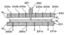
- the upper chuck 230 is divided into a plurality of, for example, three regions 230a, 230b, and 230c. These regions 230a, 230b, and 230c are provided in this order from the center of the upper chuck 230 toward the outer periphery as shown in FIG.
- the region 230a has a circular shape in plan view, and the regions 230b and 230c have an annular shape in plan view.
- Each region 230a, 230b, the 230c, the suction pipe 240a for sucking and holding the upper wafer W U as shown in FIG. 12, 240b, 240c are provided independently.
- Different vacuum pumps 241a, 241b, 241c are connected to the suction tubes 240a, 240b, 240c, respectively.
- the three regions 230a, 230b, and 230c described above may be referred to as a first region 230a, a second region 230b, and a third region 230c, respectively.
- the suction tubes 240a, 240b, and 240c may be referred to as a first suction tube 240a, a second suction tube 240b, and a third suction tube 240c, respectively.
- the vacuum pumps 241a, 241b, and 241c may be referred to as a first vacuum pump 241a, a second vacuum pump 241b, and a third vacuum pump 241c, respectively.
- a through hole 242 that penetrates the upper chuck 230 in the thickness direction is formed at the center of the upper chuck 230. Central portion of the upper chuck 230 corresponds to the central portion of the upper wafer W U which is attracted and held on the upper chuck 230. A push pin 251 of a push member 250 described later is inserted into the through hole 242.
- the pushing member 250 has a cylinder structure, and includes a pushing pin 251 and an outer cylinder 252 that serves as a guide when the pushing pin 251 moves up and down.
- the push pin 251 is movable up and down in the vertical direction through the through hole 242 by, for example, a drive unit (not shown) incorporating a motor.
- the pressing member 250, the wafer W U to be described later, at the time of bonding of W L, can be pressed by contacting the center portion of the center and lower wafer W L of the upper wafer W U.
- the upper chuck 230, the upper imaging member 253 as a second imaging member for imaging the surface W L1 of the lower wafer W L is provided.
- the upper imaging member 253 for example, a wide-angle CCD camera is used. Note that the upper imaging member 253 may be provided on the upper chuck 230.
- the lower chuck 231 is divided into a plurality of, for example, two regions 231a and 231b. These regions 231a and 231b are provided in this order from the center of the lower chuck 231 toward the outer periphery.
- the region 231a has a circular shape in plan view
- the region 231b has an annular shape in plan view.
- Each region 231a, the 231b, the suction pipe 260a for sucking and holding the upper wafer W U as shown in FIG. 12, 260b are provided independently.
- Different vacuum pumps 261a and 261b are connected to the suction pipes 260a and 260b, respectively. Therefore, the lower chuck 231, each region 231a, and is capable of setting the vacuum of the lower wafer W L per 231b.
- the outer peripheral portion of the lower chuck 231, the wafer W U, W L, or jump out from the overlapped wafer W T is the lower chuck 231, the stopper member 262 to prevent the sliding is provided.
- the stopper member 262, the top portion extends in the vertical direction so as to be positioned above the overlapped wafer W T on at least a lower chuck 231. Further, as shown in FIG. 14, the stopper member 262 is provided at a plurality of places, for example, five places on the outer peripheral portion of the lower chuck 231.
- the lower chuck 231 is provided with a lower imaging member 263 as a first imaging member that images the surface W U1 of the upper wafer W U as shown in FIG.
- a lower imaging member 263 for example, a wide-angle CCD camera is used.
- the lower imaging member 263 may be provided on the lower chuck 231.
- the above joining system 1 is provided with a control unit 300 as shown in FIG.
- the control unit 300 is a computer, for example, and has a program storage unit (not shown).
- the program storage unit stores a program for controlling processing of the wafers W U and W L and the overlapped wafer W T in the bonding system 1.
- the program storage unit also stores a program for controlling operations of driving systems such as the above-described various processing apparatuses and transfer apparatuses to realize later-described wafer bonding processing in the bonding system 1.
- the program is recorded on a computer-readable storage medium H such as a computer-readable hard disk (HD), a flexible disk (FD), a compact disk (CD), a magnetic optical desk (MO), or a memory card. May have been installed in the control unit 300 from the storage medium H.
- FIG. 15 is a flowchart showing an example of main steps of the wafer bonding process.
- the cassette C U, the cassette C L accommodating the lower wafer W L of the plurality, and the empty cassette C T is a predetermined cassette mounting plate 11 of the carry-out station 2 accommodating the wafers W U on the plurality Placed on. Thereafter, the upper wafer W U in the cassette C U is taken out by the wafer transfer device 22 is conveyed to the transition unit 50 of the third processing block G3 in the processing station 3.
- the upper wafer W U is transported to the first processing block surface activation device G1 30 by the wafer transfer apparatus 61.
- Upper wafer W U which is carried on the surface activation device 30 is mounted is passed from the wafer transfer unit 61 on the upper surface of the lower electrode 80. Thereafter, the wafer transfer device 61 leaves the surface activation device 30 and the gate valve 72 is closed.
- the vacuum pump 131 is operated, and the atmosphere inside the processing container 70 is reduced to a predetermined degree of vacuum, for example, 67 Pa to 333 Pa (0.5 Torr to 2.5 Torr) via the air inlet 130. Then, processing on the wafer W U as described below, the atmosphere in the processing chamber 70 is maintained at the predetermined degree of vacuum.
- a high voltage set to, for example, a DC voltage of 2500 V is applied from the high voltage power source 96 to the conductive film 93 of the electrostatic chuck 90.
- the upper wafer W U is electrostatically adsorbed on the upper surface of the lower electrode 80.
- the upper wafer W U electrostatically attracted to the lower electrode 80 is maintained at a predetermined temperature, for example, 25 ° C. to 30 ° C. by the heat medium in the heat medium circulation channel 82.
- the processing gas supplied from the gas supply source 122 is uniformly supplied into the processing vessel 70 from the gas outlet 125 on the lower surface of the upper electrode 110.
- a high frequency voltage of 2 MHz for example, is applied from the first high frequency power supply 106 to the lower electrode 80
- a high frequency voltage of 60 MHz is applied from the second high frequency power supply 112 to the upper electrode 110.
- an electric field is formed between the upper electrode 110 and the lower electrode 80, and the processing gas supplied into the processing container 70 is turned into plasma by the electric field.
- the plasma of the processing gas activates the surface W U1 of the upper wafer W U on the lower electrode 80 and removes organic substances on the surface W U1. Is done.
- the oxygen gas plasma in the processing plasma mainly contributes to the removal of organic substances on the surface W U1 . Further, the oxygen gas plasma can promote the oxidation of the surface W U1 of the upper wafer W U , that is, the hydrophilization.
- the argon gas plasma in the processing plasma has a certain amount of high energy, and organic substances on the surface W U1 are positively (physically) removed by the argon gas plasma. Further, the argon gas plasma has an effect of removing residual moisture contained in the atmosphere in the processing vessel 70. In this way, the surface W U1 of the upper wafer W U is activated by the processing plasma (step S1 in FIG. 15).
- the upper wafer W U is transferred to a surface hydrophilizing apparatus 40 of the second processing block G2 by the wafer transfer apparatus 61.
- Surface hydrophilizing device wafer after being carried into the 40 W U is the passed suction holding the wafer transfer apparatus 61 to the spin chuck 160.
- the pure water nozzle 173 of the standby unit 175 is moved to above the center of the upper wafer W U by the nozzle arm 171, and the scrub cleaning tool 180 is moved onto the upper wafer W U by the scrub arm 172.
- the upper wafer W U by the spin chuck 160, for supplying pure water onto the upper wafer W U from the pure water nozzle 173.
- hydroxyl groups adhere to the surface W U1 of the upper wafer W U , and the surface W U1 is hydrophilized.
- the surface W U1 of the upper wafer W U is cleaned by pure water from the pure water nozzle 173 and the scrub cleaning tool 180 (step S2 in FIG. 15).
- the upper wafer W U is transferred to the bonding apparatus 41 of the second processing block G2 by the wafer transfer apparatus 61.
- Upper wafer W U which is carried into the joining device 41 is conveyed to the position adjusting mechanism 210 by the wafer transfer body 202 via the transition 200.
- the position adjusting mechanism 210, the horizontal orientation of the upper wafer W U is adjusted (step S3 in FIG. 15).
- the upper wafer W U is transferred from the position adjusting mechanism 210 to the holding arm 221 of the inverting mechanism 220. Subsequently, in transfer region T1, by reversing the holding arm 221, the front and back surfaces of the upper wafer W U is inverted (step S4 in FIG. 15). That is, the surface W U1 of the upper wafer W U is directed downward. Incidentally, reversal of the front and rear surfaces of the upper wafer W U may be performed during movement of the reversing mechanism 220 to be described later.
- the reversing mechanism 220 is moved to the upper chuck 230 side, the upper wafer W U is transferred from the inverting mechanism 220 in the upper chuck 230.
- Upper wafer W U, the back surface W U2 is held by suction to the upper chuck 230 (step S5 in FIG. 15).
- Upper wafer W U the process waits at the upper chuck 230 to the lower wafer W L is transported to the bonding apparatus 41 described later.
- the processing of the lower wafer W L Following the on wafer W U is performed.
- the lower wafer W L in the cassette C L is taken out by the wafer transfer device 22 is conveyed to the transition unit 50 in the processing station 3.
- step S6 activation of the surface W L1 of the lower wafer W L in step S6 is the same as step S1 of the aforementioned.
- step S7 hydrophilic and cleaning of the surface W L1 of the lower wafer W L in step S7, to omit the detailed description is the same as step S2 of the above-described.
- the lower wafer W L is transported to the bonding apparatus 41 by the wafer transfer apparatus 61.
- Lower wafer W L which is transported to the bonding unit 41 is conveyed to the position adjusting mechanism 210 by the wafer transfer body 202 via the transition 200. Then the position adjusting mechanism 210, the horizontal orientation of the lower wafer W L are adjusted (step S8 in FIG. 15).
- the lower wafer W L is transferred to the lower chuck 231 by the wafer transfer body 202, it is attracted and held by the lower chuck 231 (step S9 in FIG. 15).
- all of the vacuum pumps 261a actuates the 261b, all the regions 231a of the lower chuck 231, in 231b, are evacuated lower wafer W L.
- the surface W L1 of the lower wafer W L is to face upwards, the back surface W L2 of the lower wafer W L is sucked and held by the lower chuck 231.
- a plurality of predetermined reference points A for example, four or more reference points A are formed on the surface W L1 of the lower wafer W L , and similarly, predetermined on the surface W U1 of the upper wafer W U.
- a plurality of, for example, four or more reference points B are formed.
- these reference points A and B for example, predetermined patterns formed on the wafers W L and W U are used, respectively. Then, by moving the upper imaging member 253 in the horizontal direction, the surface W L1 of the lower wafer W L is imaged.
- the lower imaging member 263 is moved in the horizontal direction, and the surface W U1 of the upper wafer W U is imaged. Thereafter, the position of the reference point A of the lower wafer W L to an upper imaging member 253 is displayed in the image captured, and the position of the reference point B of the wafer W U on the lower imaging member 263 is displayed in the image captured Consistently, the horizontal position of the lower wafer W L by the lower chuck 231 (including the horizontal direction) is adjusted. That is, the chuck drive unit 234 to move the lower chuck 231 in the horizontal direction is adjusted horizontal position of the lower wafer W L. Horizontal position of the upper wafer W U and the lower wafer W L is adjusted in this way (step S10 in FIG. 15).
- the horizontal direction of the wafers W U and W L is adjusted by the position adjusting mechanism 210 in steps S3 and S8, but fine adjustment is performed in step S10.
- the predetermined patterns formed on the wafers W L and W U are used as the reference points A and B.
- other reference points can be used.
- the outer peripheral portion and the notch portion of the wafers W L and W U can be used as the reference points.
- the chuck drive unit 234 raises the lower chuck 231 as shown in FIG. 17, to place the lower wafer W L to a predetermined position.
- the arrangement distance D 1 is a predetermined distance, the lower wafer W L so for example, as 50 ⁇ m between the surface W U1 of the surface W L1 and the upper wafer W U of the lower wafer W L.
- Vertical position of the upper wafer W U and the lower wafer W L is adjusted in this way (step S11 in FIG. 15).
- step S5 ⁇ step S11, all areas 230a of the upper chuck 230, 230b, in 230c, are evacuated upper wafer W U.
- step S9 all areas 231a of the lower chuck 231, in 231b, are evacuated lower wafer W L.
- the bonding is started between the central portion of the central portion and the lower wafer W L of the upper wafer W U which pressed (thick line portion in FIG. 18). That is, since the surface W U1 of the upper wafer W U and the surface W L1 of the lower wafer W L are activated in steps S1 and S6, respectively, first, Van der Waals force is generated between the surfaces W U1 and W L1 . The surfaces W U1 and W L1 are joined to each other. Thereafter, since the surface W U1 of the upper wafer W U and the surface W L1 of the lower wafer W L have been hydrophilized in steps S2 and S7, respectively, the hydrophilic groups between the surfaces W U1 and W L1 are hydrogen-bonded. U1 and WL1 are firmly joined to each other.
- the pushing member 250 is raised to the upper chuck 230 as shown in FIG.
- the suction pipe 260a in the lower chuck 231 to stop the evacuation of the lower wafer W L from 260b, stopping the suction and holding of the lower wafer W L by the lower chuck 231.
- the upper wafer W U and the lower wafer W L overlapped wafer bonded W T is transferred to the transition unit 51 by the wafer transfer apparatus 61, then carry out by the wafer transfer apparatus 22 of the station 2 of a predetermined cassette mounting plate 11 It is conveyed to the cassette C T.
- a series of wafers W U, bonding process of W L is completed.
- step S13 in a state of pressing by contacting the central portion of the central portion and the lower wafer W L of the upper wafer W U by pressing member 250, the center portion of the upper wafer W U toward the outer periphery from, stop evacuation of the upper wafer W U, the upper wafer W U are sequentially abut on the lower wafer W L, it is possible to bond the upper wafer W U and the lower wafer W L.
- the region 230b when stopping the evacuation of the upper wafer W U in 230c, since the central portion of the central portion and the lower wafer W L of the upper wafer W U is pressed in contact with, for example, the upper wafer W even if there is air between the U and the lower wafer W L, never deviated in the horizontal direction position of the upper wafer W U against the lower wafer W L. Therefore, the wafers W U and W L can be appropriately bonded.
- the wafer W U can suppress the generation of voids between W L, it is possible to more suitably joined wafers W U, the W L together.
- the stopper member 262 to the outer peripheral portion of the lower chuck 231 is provided, it is possible to prevent the wafer W U, W L, or popping overlapped wafer W T is the lower chuck 231, from sliding down.
- the bonding apparatus 41 includes a position adjusting mechanism 210 that adjusts the horizontal direction of the wafers W U and W L , since also has a reversing mechanism 220 for reversing the front and back surfaces of the wafer W U, it can be performed efficiently bonding the wafer W U, W L in one device.
- the bonding system 1 hydrophilizes the surface W U1 and W L1 and the surface activation apparatus 30 that activates the surfaces W U1 and W L1 of the wafers W U and W L and the surfaces W U1 and W L1. Since the surface hydrophilizing device 40 for cleaning the surfaces W U1 and W L1 is also provided, the wafers W U and W L can be efficiently bonded in one system. Accordingly, the throughput of the wafer bonding process can be further improved.
- step S12 it had abut the central portion of the central portion and the lower wafer W L of the upper wafer W U by lowering the pressing pin 251 of the pressing member 250, the lower chuck 231 may abut the central portion of the central portion and the lower wafer W L of the upper wafer W U by increasing the.
- the pushing member 250 may have an air cylinder structure. That is, in the above-described embodiment, the push pin 251 of the push member 250 is lifted and lowered by the drive unit with a built-in motor, but the raising and lowering of the push pin 251 may be controlled by air. Further, as shown in FIG.
- the pressing member 250 is provided with a measuring unit 400 that measures the amount of vertical movement of the pressing pin 251 of the pressing member 250 or the load applied to the pressing pin 251. Also good.
- the pushing member 250 has an air cylinder structure, but the driving means is not limited to this embodiment, and various means can be taken.
- step S11 the chuck drive unit 234 raises the lower chuck 231 as shown in FIG. 23, to place the lower wafer W L to a predetermined position.
- the arrangement interval D 2 is a predetermined distance, the lower wafer W L as for example a 150 ⁇ m between the surface W U1 of the surface W L1 and the upper wafer W U of the lower wafer W L. Since steps S1 to S10 prior to step S11 are the same as S1 to S10 in the above embodiment, detailed description thereof is omitted.
- step S12 further increases the lower chuck 231 as shown in FIG. 25, are brought into contact with the central portion and the central portion of the lower wafer W L of the upper wafer W U.
- the raising and lowering of the lower chuck 231 is controlled based on the measurement result of the amount of vertical movement of the push pin 251 or the load applied to the push pin 251 in the measurement unit 400. That is, if the measurement result in the measurement unit 400 has reached a predetermined value, detects a center portion of the center and lower wafer W L of the upper wafer W U is in contact with the lower chuck 231, rise of the lower chuck 231 Stop.
- the raising and lowering of the lower chuck 231 can be strictly controlled by controlling the encoder of the chuck driving unit 234. And thus abut against the central portion of the central portion and the lower wafer W L of the upper wafer W U, to press the central portion of the central portion and the lower wafer W L of the on the wafer W U by pressing member 250. Then, the bonding is started between the central portion of the central portion and the lower wafer W L of the upper wafer W U which pressed (thick line portion in FIG. 25).
- step S13 while pressing the center portion of the center and lower wafer W L of the upper wafer W U by pressing member 250, toward the outer periphery from the center of the upper wafer W U, the on wafer W U are sequentially abut on the lower wafer W L and bonding the lower wafer W L and the lower wafer W L. Since step S13 is the same as S13 in the above embodiment, detailed description thereof is omitted.
- the raising and lowering of the lower chuck 231 can be strictly controlled by controlling the encoder of the chuck driving unit 234, so that the push pin 250 can be driven by an air cylinder. Further, since the lifting of the lower chuck 231 is tightly controlled, the upper wafer W U and the lower wafer W L is never collide. Therefore, the device structure while simply, the center portion of the center and lower wafer W L of the upper wafer W U can be appropriately abut.
- the raising and lowering of the lower chuck 231 is controlled based on the measurement result of the measuring unit 400, so-called feedforward control that controls the raising and lowering of the lower chuck 231 in real time can be performed. Then, for example, the raising / lowering of the lower chuck 231 can be more accurately controlled as compared with the case where the raising / lowering of the lower chuck 231 is controlled by a predetermined raising / lowering amount. Therefore, it is possible to more appropriately contact the central portion of the central portion and the lower wafer W L of the upper wafer W U.
- the lower chuck 231 can be moved up and down in the vertical direction and movable in the horizontal direction by the chuck driving unit 234, but the upper chuck 230 can be moved up and down in the vertical direction or moved in the horizontal direction. You may comprise. Further, both the upper chuck 230 and the lower chuck 231 may be configured to be vertically movable and movable in the horizontal direction.
- the surfaces W U1 and W L1 may be more activated.
- oxygen gas or argon gas may be used as the processing gas to be converted into plasma in the surface activation device 30, but it is more preferable to use nitrogen gas. This is because the use of nitrogen gas produces more hydroxyl groups (—OH) than the use of oxygen gas or argon gas. Then, this hydroxyl group, the wafer W U, W L is joined more firmly.
- the bonding time of the wafers W U and W L in the bonding apparatus 41 is further shortened, and bonding is started as soon as the wafers W U and W L come into contact with each other. since, it is possible to further reduce the positional deviation of the wafer W U, W L.
- the present invention is not limited to such examples. It is obvious for those skilled in the art that various changes or modifications can be conceived within the scope of the idea described in the claims, and these naturally belong to the technical scope of the present invention. It is understood.
- the present invention is not limited to this example and can take various forms.
- the present invention can also be applied to a case where the substrate is another substrate such as an FPD (flat panel display) other than a wafer or a mask reticle for a photomask.
- FPD flat panel display
Abstract
The present invention is a junction device for joining substrates to one another that has: a first holding member for causing a first substrate to adhere to and be held on the lower surface thereof; a second holding member that is provided below the first holding member, and has a second substrate mounted on the upper surface thereof and held thereon; and a pushing member that is provided on the first holding member and applies pressure to the center section of the first substrate by pushing thereon. Therein, the first holding member is divided into multiple regions from the center section toward the peripheral sections, and each of the regions is capable of being set for vacuum drawing of the first substrate.
Description
本発明は、基板同士を接合する接合装置、接合システム及び接合方法に関する。
The present invention relates to a bonding apparatus, a bonding system, and a bonding method for bonding substrates together.
近年、半導体デバイスの高集積化が進んでいる。高集積化した複数の半導体デバイスを水平面内で配置し、これら半導体デバイスを配線で接続して製品化する場合、配線長が増大し、それにより配線の抵抗が大きくなること、また配線遅延が大きくなることが懸念される。
In recent years, higher integration of semiconductor devices has progressed. When a plurality of highly integrated semiconductor devices are arranged in a horizontal plane and these semiconductor devices are connected by wiring to produce a product, the wiring length increases, thereby increasing the wiring resistance and wiring delay. There is concern about becoming.
そこで、半導体デバイスを3次元に積層する3次元集積技術を用いることが提案されている。この3次元集積技術においては、例えば貼り合わせ装置を用いて、2枚の半導体ウェハ(以下、「ウェハ」という。)の接合が行われる。例えば貼り合わせ装置は、2枚のウェハを上下に配置した状態(以下、上側のウェハを「上ウェハ」といい、下側のウェハを「下ウェハ」という。)で収容するチャンバーと、チャンバー内に設けられ、上ウェハの中心部分を押圧する押動ピンと、上ウェハの外周を支持すると共に、当該上ウェハの外周から退避可能なスペーサと、を有している。かかる貼り合わせ装置を用いた場合、ウェハ間のボイドの発生を抑制するため、チャンバー内を真空雰囲気にしてウェハ同士の接合が行われる。具体的には、先ず、上ウェハをスペーサで支持した状態で、押動ピンにより上ウェハの中心部分を押圧し、当該中心部分を下ウェハに当接させる。その後、上ウェハを支持しているスペーサを退避させて、上ウェハの全面を下ウェハの全面に当接させて貼り合わせる(特許文献1)。
Therefore, it has been proposed to use a three-dimensional integration technique in which semiconductor devices are stacked three-dimensionally. In this three-dimensional integration technique, two semiconductor wafers (hereinafter referred to as “wafers”) are bonded using, for example, a bonding apparatus. For example, the bonding apparatus includes a chamber that accommodates two wafers arranged vertically (hereinafter, the upper wafer is referred to as an “upper wafer” and the lower wafer is referred to as a “lower wafer”), And a push pin that presses the center portion of the upper wafer, and a spacer that supports the outer periphery of the upper wafer and can be retracted from the outer periphery of the upper wafer. When such a bonding apparatus is used, the wafers are bonded to each other in a vacuum atmosphere in order to suppress the generation of voids between the wafers. Specifically, first, in a state where the upper wafer is supported by the spacer, the central portion of the upper wafer is pressed by the push pin, and the central portion is brought into contact with the lower wafer. Thereafter, the spacer supporting the upper wafer is retracted, and the entire surface of the upper wafer is brought into contact with the entire surface of the lower wafer and bonded together (Patent Document 1).
しかしながら、特許文献1に記載の貼り合わせ装置を用いた場合、チャンバー内全体を真空雰囲気にする必要があるため、ウェハをチャンバー内に収容してから真空雰囲気を形成するのに多大な時間を要する。この結果、ウェハ接合処理全体のスループットが低下することがあった。
However, when the bonding apparatus described in Patent Document 1 is used, it is necessary to make the entire chamber in a vacuum atmosphere, so it takes a long time to form the vacuum atmosphere after the wafer is accommodated in the chamber. . As a result, the throughput of the entire wafer bonding process may be reduced.
また、かかる貼り合わせ装置を用いた場合、押動ピンにより上ウェハの中心部分を押圧する際、当該上ウェハはスペーサで支持されているだけなので、下ウェハに対する上ウェハの位置がずれるおそれがあった。
In addition, when such a bonding apparatus is used, when the center portion of the upper wafer is pressed by the push pin, the upper wafer is only supported by the spacer, and therefore the position of the upper wafer may be shifted with respect to the lower wafer. It was.
本発明は、かかる点に鑑みてなされたものであり、基板間のボイドの発生を抑制しつつ、基板同士の接合を適切に効率よく行うことを目的とする。
The present invention has been made in view of such a point, and an object thereof is to appropriately and efficiently bond substrates together while suppressing the generation of voids between the substrates.
前記の目的を達成するため、本発明は、基板同士を接合する接合装置であって、下面に第1の基板を吸着保持する第1の保持部材と、前記第1の保持部材の下方に設けられ、上面に第2の基板を載置して保持する第2の保持部材と、前記第1の保持部材に設けられ、第1の基板の中心部を押圧する押動部材と、を有し、前記第1の保持部材は、中心部から外周部に向けて複数の領域に区画され、当該領域毎に第1の基板の真空引きを設定可能である。
In order to achieve the above object, the present invention is a bonding apparatus for bonding substrates to each other, and is provided below the first holding member, a first holding member that sucks and holds the first substrate on the lower surface. And a second holding member for placing and holding the second substrate on the upper surface, and a pushing member provided on the first holding member and pressing the central portion of the first substrate. The first holding member is partitioned into a plurality of regions from the central portion toward the outer peripheral portion, and evacuation of the first substrate can be set for each region.
本発明によれば、押動部材によって第1の基板の中心部と第2の基板の中心部を当接させて押圧した状態で、第1の保持部材において外周部の領域の第1の基板の真空引きを停止し、第1の基板の中心部から外周部に向けて、当該第1の基板を第2の基板に順次当接させ、第1の基板と第2の基板を接合することができる。そうすると、第1の保持部材による外周部の領域の真空引きを停止する際には、第1の基板の中心部と第2の基板の中心部が当接して押圧されているので、例えば第1の基板と第2の基板との間に空気がある場合でも、第2の基板に対する第1の基板の水平方向の位置がずれることがない。したがって、基板の接合を適切に行うことができる。また、第1の基板の中心部から外周部に向けて第1の基板を第2の基板に順次当接させているので、例えば第1の基板と第2の基板との間にボイドとなりうる空気が存在している場合でも、空気は第1の基板が第2の基板と当接している箇所より常に外周部側に存在することになる。そうすると、当該空気を基板間において中心部から外周部に逃がすことができる。したがって、基板間のボイドの発生を抑制ができ、基板同士をさらに適切に接合することができる。しかも、本発明によれば、従来のように基板を接合する際の雰囲気を真空雰囲気にする必要がないので、基板の接合を短時間で効率よく行うことができ、基板接合処理のスループットを向上させることができる。
According to the present invention, the first substrate in the outer peripheral region of the first holding member in a state where the central portion of the first substrate and the central portion of the second substrate are brought into contact with and pressed by the pushing member. Vacuuming is stopped, the first substrate is sequentially brought into contact with the second substrate from the center portion of the first substrate toward the outer peripheral portion, and the first substrate and the second substrate are bonded together. Can do. Then, when stopping the evacuation of the outer peripheral region by the first holding member, the central portion of the first substrate and the central portion of the second substrate are in contact with each other and pressed. Even when there is air between the second substrate and the second substrate, the horizontal position of the first substrate with respect to the second substrate does not shift. Accordingly, the substrates can be appropriately bonded. Further, since the first substrate is sequentially brought into contact with the second substrate from the center portion of the first substrate toward the outer peripheral portion, for example, a void can be formed between the first substrate and the second substrate. Even when air is present, the air is always present on the outer peripheral side from the portion where the first substrate is in contact with the second substrate. If it does so, the said air can be escaped from a center part to an outer peripheral part between board | substrates. Therefore, generation | occurrence | production of the void between board | substrates can be suppressed and board | substrates can be joined more appropriately. Moreover, according to the present invention, it is not necessary to use a vacuum atmosphere when bonding the substrates as in the prior art, so that the substrates can be bonded efficiently in a short time, and the throughput of the substrate bonding process is improved. Can be made.
別な観点による本発明は、前記接合装置を備えた接合システムであって、前記接合装置を備えた処理ステーションと、第1の基板、第2の基板又は第1の基板と第2の基板が接合された重合基板をそれぞれ複数保有可能で、且つ前記処理ステーションに対して第1の基板、第2の基板又は重合基板を搬入出する搬入出ステーションと、を備えている。前記処理ステーションは、第1の基板又は第2の基板の接合される表面を活性化する表面活性化装置と、前記表面活性化装置で活性化された第1の基板又は第2の基板の表面を親水化する表面親水化装置と、前記表面活性化装置、前記表面親水化装置及び前記接合装置に対して、第1の基板、第2の基板又は重合基板を搬送するための搬送領域と、を有している。前記接合装置では、前記表面親水化装置で表面が親水化された第1の基板と第2の基板を接合する。
Another aspect of the present invention is a bonding system including the bonding apparatus, wherein a processing station including the bonding apparatus, a first substrate, a second substrate, or a first substrate and a second substrate are provided. A plurality of bonded superposed substrates can be held, and a loading / unloading station for loading / unloading the first substrate, the second substrate or the superposed substrate with respect to the processing station is provided. The processing station includes a surface activation device that activates a surface to be bonded of the first substrate or the second substrate, and a surface of the first substrate or the second substrate activated by the surface activation device. A surface hydrophilizing device that hydrophilizes, a transport region for transporting the first substrate, the second substrate, or the polymerization substrate to the surface activating device, the surface hydrophilizing device, and the bonding device; have. In the bonding apparatus, the first substrate and the second substrate whose surfaces are hydrophilized by the surface hydrophilizing apparatus are bonded.
また別な観点による本発明は、接合装置を用いて基板同士を接合する接合方法であって、前記接合装置は、下面に第1の基板を吸着保持する第1の保持部材と、前記第1の保持部材の下方に設けられ、上面に第2の基板を載置して保持する第2の保持部材と、前記第1の保持部材に設けられ、第1の基板の中心部を押圧する押動部材と、を有している。前記第1の保持部材は、中心部から外周部に向けて複数の領域に区画され、当該領域毎に第1の基板の真空引きを設定可能であり、前記接合方法は、前記第1の保持部材に保持された第1の基板と、前記第2の保持部材に保持された第2の基板とを所定の間隔で対向配置する配置工程と、その後、前記第1の保持部材において中心部の領域の第1の基板の真空引きを停止し、前記押動部材によって第1の基板の中心部と第2の基板の中心部を当接させて押圧する押圧工程と、その後、第1の基板の中心部と第2の基板の中心部が押圧された状態で、第1の保持部材において外周部の領域の第1の基板の真空引きを停止し、第1の基板の中心部から外周部に向けて、当該第1の基板を第2の基板に順次当接させ、第1の基板と第2の基板を接合する接合工程と、を有する。
According to another aspect of the present invention, there is provided a bonding method for bonding substrates using a bonding apparatus, wherein the bonding apparatus includes a first holding member that holds the first substrate by suction on the lower surface, and the first holding member. A second holding member provided on the upper surface for holding and holding the second substrate, and a pressing member provided on the first holding member for pressing the central portion of the first substrate. A moving member. The first holding member is partitioned into a plurality of regions from the central portion toward the outer peripheral portion, and evacuation of the first substrate can be set for each region, and the bonding method includes the first holding member. An arrangement step of disposing the first substrate held by the member and the second substrate held by the second holding member so as to face each other at a predetermined interval; and thereafter, in the central portion of the first holding member A pressing step of stopping evacuation of the first substrate in the region and bringing the central portion of the first substrate into contact with the central portion of the second substrate by the pressing member, and then the first substrate In the state where the central portion of the first substrate and the central portion of the second substrate are pressed, the first holding member stops evacuation of the first substrate in the region of the outer peripheral portion, and the outer peripheral portion starts from the central portion of the first substrate. The first substrate is sequentially brought into contact with the second substrate toward the substrate, and the first substrate and the second substrate are bonded together. It has a bonding step that, a.
本発明によれば、基板間のボイドの発生を抑制しつつ、基板の同士の接合を適切に効率よく行うことができる。
According to the present invention, it is possible to appropriately and efficiently bond the substrates together while suppressing the generation of voids between the substrates.
以下、本発明の実施の形態について説明する。図1は、本実施の形態にかかる接合システム1の構成の概略を示す平面図である。図2は、接合システム1の内部構成の概略を示す側面図である。
Hereinafter, embodiments of the present invention will be described. FIG. 1 is a plan view showing the outline of the configuration of the joining system 1 according to the present embodiment. FIG. 2 is a side view illustrating the outline of the internal configuration of the joining system 1.
接合システム1では、図3に示すように例えば2枚の基板としてのウェハWU、WLを接合する。以下、上側に配置されるウェハを、第1の基板としての「上ウェハWU」といい、下側に配置されるウェハを、第2の基板としての「下ウェハWL」という。また、上ウェハWUが接合される接合面を「表面WU1」といい、当該表面WU1と反対側の面を「裏面WU2」という。同様に、下ウェハWLが接合される接合面を「表面WL1」といい、当該表面WL1と反対側の面を「裏面WL2」という。そして、接合システム1では、上ウェハWUと下ウェハWLを接合して、重合基板としての重合ウェハWTを形成する。
In the interface system 1, bonding the wafer W U, W L as substrate, for example two as shown in FIG. Hereinafter, the wafer disposed on the upper side is referred to as “upper wafer W U ” as the first substrate, and the wafer disposed on the lower side is referred to as “lower wafer W L ” as the second substrate. Further, a bonding surface to which the upper wafer W U is bonded is referred to as “front surface W U1 ”, and a surface opposite to the front surface W U1 is referred to as “back surface W U2 ”. Similarly, the bonding surface to which the lower wafer W L is bonded is referred to as “front surface W L1 ”, and the surface opposite to the front surface W L1 is referred to as “back surface WL 2 ”. Then, in the bonding system 1, by joining the upper wafer W U and the lower wafer W L, to form the overlapped wafer W T as a polymerization substrate.
接合システム1は、図1に示すように例えば外部との間で複数のウェハWU、WL、複数の重合ウェハWTをそれぞれ収容可能なカセットCU、CL、CTが搬入出される搬入出ステーション2と、ウェハWU、WL、重合ウェハWTに対して所定の処理を施す各種処理装置を備えた処理ステーション3とを一体に接続した構成を有している。
As shown in FIG. 1, the bonding system 1 carries in and out cassettes C U , C L , and C T that can accommodate a plurality of wafers W U and W L and a plurality of superposed wafers W T , respectively, with the outside. The loading / unloading station 2 and the processing station 3 including various processing apparatuses that perform predetermined processing on the wafers W U , W L , and the overlapped wafer W T are integrally connected.
搬入出ステーション2には、カセット載置台10が設けられている。カセット載置台10には、複数、例えば4つのカセット載置板11が設けられている。カセット載置板11は、水平方向のX方向(図1中の上下方向)に一列に並べて配置されている。これらのカセット載置板11には、接合システム1の外部に対してカセットCU、CL、CTを搬入出する際に、カセットCU、CL、CTを載置することができる。このように、搬入出ステーション2は、複数の上ウェハWU、複数の下ウェハWL、複数の重合ウェハWTを保有可能に構成されている。なお、カセット載置板11の個数は、本実施の形態に限定されず、任意に決定することができる。また、カセットの1つを異常ウェハの回収用として用いてもよい。すなわち、種々の要因で上ウェハWUと下ウェハWLとの接合に異常が生じたウェハを、他の正常な重合ウェハWTと分離することができるカセットである。本実施の形態においては、複数のカセットCTのうち、1つのカセットCTを異常ウェハの回収用として用い、他のカセットCTを正常な重合ウェハWTの収容用として用いている。
The loading / unloading station 2 is provided with a cassette mounting table 10. The cassette mounting table 10 is provided with a plurality of, for example, four cassette mounting plates 11. The cassette mounting plates 11 are arranged in a line in the horizontal X direction (vertical direction in FIG. 1). These cassette mounting plates 11, cassettes C U to the outside of the interface system 1, C L, when loading and unloading the C T, a cassette C U, C L, it is possible to place the C T . Thus, carry-out station 2, a wafer over multiple W U, a plurality of lower wafer W L, and is configured to be held by a plurality of overlapped wafer W T. The number of cassette mounting plates 11 is not limited to the present embodiment, and can be arbitrarily determined. One of the cassettes may be used for collecting abnormal wafers. That is a cassette a wafer abnormality occurs in the bonding of the upper wafer W U and the lower wafer W L, it can be separated from the other normal overlapped wafer W T by various factors. In the present embodiment, among the plurality of cassettes C T, using a one cassette C T for the recovery of the abnormal wafer, and using other cassettes C T for the accommodation of a normal overlapped wafer W T.
搬入出ステーション2には、カセット載置台10に隣接してウェハ搬送部20が設けられている。ウェハ搬送部20には、X方向に延伸する搬送路21上を移動自在なウェハ搬送装置22が設けられている。ウェハ搬送装置22は、鉛直方向及び鉛直軸周り(θ方向)にも移動自在であり、各カセット載置板11上のカセットCU、CL、CTと、後述する処理ステーション3の第3の処理ブロックG3のトランジション装置50、51との間でウェハWU、WL、重合ウェハWTを搬送できる。
In the loading / unloading station 2, a wafer transfer unit 20 is provided adjacent to the cassette mounting table 10. The wafer transfer unit 20 is provided with a wafer transfer device 22 that is movable on a transfer path 21 extending in the X direction. The wafer transfer device 22 is also movable in the vertical direction and around the vertical axis (θ direction), and includes cassettes C U , C L , C T on each cassette mounting plate 11 and a third of the processing station 3 described later. The wafers W U and W L and the superposed wafer W T can be transferred between the transition devices 50 and 51 in the processing block G3.
処理ステーション3には、各種装置を備えた複数例えば3つの処理ブロックG1、G2、G3が設けられている。例えば処理ステーション3の正面側(図1のX方向負方向側)には、第1の処理ブロックG1が設けられ、処理ステーション3の背面側(図1のX方向正方向側)には、第2の処理ブロックG2が設けられている。また、処理ステーション3の搬入出ステーション2側(図1のY方向負方向側)には、第3の処理ブロックG3が設けられている。
The processing station 3 is provided with a plurality of, for example, three processing blocks G1, G2, G3 provided with various devices. For example, a first processing block G1 is provided on the front side of the processing station 3 (X direction negative direction side in FIG. 1), and on the back side of the processing station 3 (X direction positive direction side in FIG. 1) Two processing blocks G2 are provided. Further, a third processing block G3 is provided on the loading / unloading station 2 side of the processing station 3 (Y direction negative direction side in FIG. 1).
例えば第1の処理ブロックG1には、ウェハWU、WLの表面WU1、WL1を活性化する表面活性化装置30が配置されている。
For example, in the first processing block G1, a surface activation device 30 that activates the surfaces W U1 and W L1 of the wafers W U and W L is arranged.
例えば第2の処理ブロックG2には、例えば純水によってウェハWU、WLの表面WU1、WL1を親水化すると共に当該表面WU1、WL1を洗浄する表面親水化装置40、ウェハWU、WLを接合する接合装置41が、搬入出ステーション2側からこの順で水平方向のY方向に並べて配置されている。
For example, the second processing block G2 includes, for example, a surface hydrophilizing device 40 that hydrophilizes the surfaces W U1 and W L1 of the wafers W U and W L with pure water and cleans the surfaces W U1 and W L1. U, bonding device 41 for bonding the W L are arranged side by side in the horizontal direction of the Y-direction in this order from the carry-out station 2 side.
例えば第3の処理ブロックG3には、図2に示すようにウェハWU、WL、重合ウェハWTのトランジション装置50、51が下から順に2段に設けられている。
For example, the third processing block G3, the wafer W U as shown in FIG. 2, W L, a transition unit 50, 51 of the overlapped wafer W T are provided in two tiers from the bottom in order.
図1に示すように第1の処理ブロックG1~第3の処理ブロックG3に囲まれた領域には、ウェハ搬送領域60が形成されている。ウェハ搬送領域60には、例えばウェハ搬送装置61が配置されている。
As shown in FIG. 1, a wafer transfer region 60 is formed in a region surrounded by the first processing block G1 to the third processing block G3. For example, a wafer transfer device 61 is disposed in the wafer transfer region 60.
ウェハ搬送装置61は、例えば鉛直方向、水平方向(Y方向、X方向)及び鉛直軸周りに移動自在な搬送アームを有している。ウェハ搬送装置61は、ウェハ搬送領域60内を移動し、周囲の第1の処理ブロックG1、第2の処理ブロックG2及び第3の処理ブロックG3内の所定の装置にウェハWU、WL、重合ウェハWTを搬送できる。
The wafer transfer device 61 has, for example, a transfer arm that can move around the vertical direction, horizontal direction (Y direction, X direction), and vertical axis. The wafer transfer device 61 moves in the wafer transfer region 60, and adds wafers W U , W L , and W to predetermined devices in the surrounding first processing block G1, second processing block G2, and third processing block G3. You can transfer the overlapping wafer W T.
次に、上述した表面活性化装置30の構成について説明する。表面活性化装置30は、図4に示すように内部を密閉可能な処理容器70を有している。処理容器70のウェハ搬送領域60側の側面には、ウェハWU、WLの搬入出口71が形成され、当該搬入出口71にはゲートバルブ72が設けられている。
Next, the configuration of the surface activation device 30 described above will be described. As shown in FIG. 4, the surface activation device 30 has a processing container 70 capable of sealing the inside. The side surface of the wafer transfer area 60 side of the processing container 70, the wafer W U, the transfer port 71 of W L is formed, the gate valve 72 is provided in the transfer port 71.
処理容器70の内部には、ウェハWU、WLを載置させるための下部電極80が設けられている。下部電極80は、例えばアルミニウムなどの導電性材料で構成される。下部電極80の下方には、例えばモータなどを備えた駆動部81が設けられている。この駆動部81により、下部電極80は昇降自在になっている。
A lower electrode 80 for placing the wafers W U and W L is provided inside the processing container 70. The lower electrode 80 is made of a conductive material such as aluminum. Below the lower electrode 80, for example, a drive unit 81 including a motor or the like is provided. The lower electrode 80 can be moved up and down by the drive unit 81.
下部電極80の内部には、熱媒循環流路82が設けられている。熱媒循環流路82には、温調手段(図示せず)により適当な温度に温度調節された熱媒が熱媒導入管83を介して導入される。熱媒導入管83から導入された熱媒は熱媒循環流路82内を循環し、これによって、下部電極80が所望の温度に調節される。そして、下部電極80の熱が、下部電極80の上面に載置されたウェハWU、WLに伝達されて、ウェハWU、WLが所望の温度に調節される。
A heat medium circulation channel 82 is provided inside the lower electrode 80. A heat medium whose temperature is adjusted to an appropriate temperature by a temperature adjusting means (not shown) is introduced into the heat medium circulation passage 82 via a heat medium introduction pipe 83. The heat medium introduced from the heat medium introduction pipe 83 circulates in the heat medium circulation channel 82, whereby the lower electrode 80 is adjusted to a desired temperature. The heat of the lower electrode 80, the wafer W U which is placed on the upper surface of the lower electrode 80, is transmitted to the W L, the wafer W U, W L is adjusted to a desired temperature.
なお、下部電極80の温度を調節する温度調節機構は、熱媒循環流路82に限定されず、冷却ジャケット、ヒータ等、その他の機構を用いることもできる。
Note that the temperature adjustment mechanism for adjusting the temperature of the lower electrode 80 is not limited to the heat medium circulation passage 82, and other mechanisms such as a cooling jacket and a heater can also be used.
下部電極80の上部は、ウェハWU、WLを静電吸着するための静電チャック90に構成されている。静電チャック90は、例えばポリイミド樹脂などの高分子絶縁材料からなる2枚のフィルム91、92の間に、例えば銅箔などの導電膜93を配置した構造を有している。導電膜93は、配線94、コイル等のフィルタ95を介して高圧電源96に接続されている。プラズマ処理時には、高圧電源96から、任意の直流電圧に設定された高電圧が、フィルタ95で高周波をカットされて、導電膜93に印加される。こうして導電膜93に印加された高電圧により発生されたクーロン力によって、下部電極80の上面(静電チャック90の上面)にウェハWU、WLが静電吸着させられる。
The upper part of the lower electrode 80 is configured as an electrostatic chuck 90 for electrostatically attracting the wafers W U and W L. The electrostatic chuck 90 has a structure in which a conductive film 93 such as a copper foil is disposed between two films 91 and 92 made of a polymer insulating material such as polyimide resin. The conductive film 93 is connected to a high-voltage power source 96 through a wiring 94 and a filter 95 such as a coil. At the time of the plasma processing, a high voltage set to an arbitrary DC voltage is cut from the high voltage power source 96 by the filter 95 and applied to the conductive film 93. Thus by the Coulomb force generated by the high voltage applied to the conductive film 93, wafer W U to the upper surface (the upper surface of the electrostatic chuck 90) of the lower electrode 80, W L is brought into electrostatic attraction.
下部電極80の上面には、ウェハWU、WLの裏面に向けて伝熱ガスを供給する複数の伝熱ガス供給穴100が設けられている。図5に示すように複数の伝熱ガス供給穴100は、下部電極80の上面において、複数の同心円状に均一に配置されている。
The upper surface of the lower electrode 80, the wafer W U, a plurality of heat transfer gas supply holes 100 for supplying a heat transfer gas toward the rear surface of the W L is provided. As shown in FIG. 5, the plurality of heat transfer gas supply holes 100 are uniformly arranged in a plurality of concentric circles on the upper surface of the lower electrode 80.
各伝熱ガス供給穴100には、図4に示すように伝熱ガス供給管101が接続されている。伝熱ガス供給管101はガス供給源(図示せず)に連通し、当該ガス供給源よりヘリウムなどの伝熱ガスが、下部電極80の上面とウェハWU、WLの裏面WU2、WL2との間に形成される微小空間に供給される。これにより、下部電極80の上面からウェハWU、WLに効率よく熱が伝達される。
As shown in FIG. 4, a heat transfer gas supply pipe 101 is connected to each heat transfer gas supply hole 100. The heat transfer gas supply pipe 101 communicates with a gas supply source (not shown), and a heat transfer gas such as helium is transferred from the gas supply source to the upper surface of the lower electrode 80 and the back surfaces W U2 and W of the wafers W U and W L. It is supplied to a minute space formed between L2 . Thereby, heat is efficiently transmitted from the upper surface of the lower electrode 80 to the wafers W U and W L.
なお、ウェハWU、WLに十分効率よく熱が伝達される場合には、伝熱ガス供給穴100と伝熱ガス供給管101を省略してもよい。
Incidentally, the wafer W U, if sufficient heat is efficiently transferred to W L may be omitted heat transfer gas supply holes 100 and the heat transfer gas supply pipe 101.
下部電極80の上面の周囲には、下部電極80の上面に載置されたウェハWU、WLの外周を囲むように、環状のフォーカスリング102が配置されている。フォーカスリング102は、反応性イオンを引き寄せない絶縁性または導電性の材料からなり、反応性イオンを、内側のウェハWU、WLにだけ効果的に入射せしめるように作用する。
Around the upper surface of the lower electrode 80, the wafer W U which is placed on the upper surface of the lower electrode 80, so as to surround the outer periphery of W L, an annular focus ring 102 is disposed. The focus ring 102 is made of an insulating or conductive material that does not attract reactive ions, and acts so that the reactive ions are effectively incident only on the inner wafers W U and W L.
下部電極80と処理容器70の内壁との間には、複数のバッフル孔が設けられた排気リング103が配置されている。この排気リング103により、処理容器70内の雰囲気が処理容器70内から均一に排気される。
An exhaust ring 103 having a plurality of baffle holes is disposed between the lower electrode 80 and the inner wall of the processing vessel 70. By the exhaust ring 103, the atmosphere in the processing container 70 is uniformly exhausted from the processing container 70.
下部電極80の下面には、中空に成形された導体よりなる給電棒104が接続されている。給電棒104には、例えばブロッキングコンデンサなどから成る整合器105を介して、第1の高周波電源106が接続されている。プラズマ処理時には、第1の高周波電源106から、例えば2MHzの高周波電圧が、下部電極80に印加される。
A power feeding rod 104 made of a hollow conductor is connected to the lower surface of the lower electrode 80. A first high-frequency power source 106 is connected to the power feed rod 104 via a matching unit 105 made of, for example, a blocking capacitor. During the plasma processing, a high frequency voltage of 2 MHz, for example, is applied to the lower electrode 80 from the first high frequency power supply 106.
下部電極80の上方には、上部電極110が配置されている。下部電極80の上面と上部電極110の下面は、互いに平行に、所定の間隔をあけて対向して配置されている。下部電極80の上面と上部電極110の下面の間隔は、駆動部81により調節される。
An upper electrode 110 is disposed above the lower electrode 80. The upper surface of the lower electrode 80 and the lower surface of the upper electrode 110 are arranged in parallel with each other with a predetermined distance therebetween. A distance between the upper surface of the lower electrode 80 and the lower surface of the upper electrode 110 is adjusted by the driving unit 81.
上部電極110には、例えばブロッキングコンデンサなどから成る整合器111を介して第2の高周波電源112が接続されている。プラズマ処理時には、第2の高周波電源112から、例えば60MHzの高周波電圧が、上部電極110に印加される。このように、第1の高周波電源106と第2の高周波電源112から下部電極80と上部電極110に高周波電圧が印加されることにより、処理容器70の内部にプラズマが生成される。
A second high frequency power source 112 is connected to the upper electrode 110 via a matching unit 111 made of, for example, a blocking capacitor. During the plasma processing, a high frequency voltage of 60 MHz, for example, is applied to the upper electrode 110 from the second high frequency power supply 112. As described above, the high frequency voltage is applied to the lower electrode 80 and the upper electrode 110 from the first high frequency power source 106 and the second high frequency power source 112, thereby generating plasma in the processing container 70.
なお、静電チャック90の導電膜93に高電圧を印加する高圧電源96、下部電極80に高周波電圧を印加する第1の高周波電源106、上部電極110に高周波電圧を印加する第2の高周波電源112は、後述する制御部300によって制御される。
A high voltage power supply 96 that applies a high voltage to the conductive film 93 of the electrostatic chuck 90, a first high frequency power supply 106 that applies a high frequency voltage to the lower electrode 80, and a second high frequency power supply that applies a high frequency voltage to the upper electrode 110. 112 is controlled by the control part 300 mentioned later.
上部電極110の内部には中空部120が形成されている。中空部120には、ガス供給管121が接続されている。ガス供給管121は、内部に処理ガスを貯留するガス供給源122に連通している。また、ガス供給管121には、処理ガスの流れを制御するバルブや流量調節部等を含む供給機器群123が設けられている。そして、ガス供給源122から供給された処理ガスは、供給機器群123で流量制御され、ガス供給管121を介して、上部電極110の中空部120に導入される。なお、処理ガスには、例えば酸素ガス、窒素ガス、アルゴンガス等が用いられる。
A hollow portion 120 is formed inside the upper electrode 110. A gas supply pipe 121 is connected to the hollow portion 120. The gas supply pipe 121 communicates with a gas supply source 122 that stores processing gas therein. Further, the gas supply pipe 121 is provided with a supply device group 123 including a valve for controlling the flow of the processing gas, a flow rate adjusting unit and the like. Then, the flow rate of the processing gas supplied from the gas supply source 122 is controlled by the supply device group 123 and is introduced into the hollow portion 120 of the upper electrode 110 via the gas supply pipe 121. For example, oxygen gas, nitrogen gas, argon gas or the like is used as the processing gas.
中空部120の内部には、処理ガスの均一拡散を促進するためのバッフル板124が設けられている。バッフル板124には、多数の小孔が設けられている。上部電極110の下面には、中空部120から処理容器70の内部に処理ガスを噴出させる多数のガス噴出口125が形成されている。
In the hollow portion 120, a baffle plate 124 for promoting uniform diffusion of the processing gas is provided. The baffle plate 124 is provided with a large number of small holes. On the lower surface of the upper electrode 110, a large number of gas jets 125 for ejecting a processing gas from the hollow portion 120 into the processing container 70 are formed.
処理容器70の下方には、吸気口130が形成されている。吸気口130には、処理容器70の内部の雰囲気を所定の真空度まで減圧する真空ポンプ131に連通する吸気管132が接続されている。
A suction port 130 is formed below the processing container 70. An intake pipe 132 that communicates with a vacuum pump 131 that reduces the atmosphere inside the processing container 70 to a predetermined degree of vacuum is connected to the intake port 130.
なお、下部電極80の下方には、ウェハWU、WLを下方から支持し昇降させるための昇降ピン(図示せず)が設けられている。昇降ピンは、下部電極80に形成された貫通孔(図示せず)を挿通し、下部電極80の上面から突出可能になっている。
Note that below the lower electrode 80, the wafer W U, the lift pins for supporting and elevating the the W L from below (not shown) is provided. The elevating pin is inserted through a through hole (not shown) formed in the lower electrode 80 and can protrude from the upper surface of the lower electrode 80.
次に、上述した表面親水化装置40の構成について説明する。表面親水化装置40は、図6に示すように内部を密閉可能な処理容器150を有している。処理容器150のウェハ搬送領域60側の側面には、図7に示すようにウェハWU、WLの搬入出口151が形成され、当該搬入出口151には開閉シャッタ152が設けられている。
Next, the structure of the surface hydrophilization apparatus 40 mentioned above is demonstrated. As shown in FIG. 6, the surface hydrophilizing device 40 has a processing container 150 capable of sealing the inside. The side surface of the wafer transfer area 60 side of the processing chamber 150, the wafer W U, the transfer port 151 of the W L is formed as shown in FIG. 7, the opening and closing a shutter 152 is provided to the out port 151.
処理容器150内の中央部には、図6に示すようにウェハWU、WLを保持して回転させるスピンチャック160が設けられている。スピンチャック160は、水平な上面を有し、当該上面には、例えばウェハWU、WLを吸引する吸引口(図示せず)が設けられている。この吸引口からの吸引により、ウェハWU、WLをスピンチャック160上に吸着保持できる。
A spin chuck 160 that holds and rotates the wafers W U and W L is provided at the center of the processing container 150 as shown in FIG. The spin chuck 160 has a horizontal upper surface, and the upper surface is, for example, the wafer W U, suction port for sucking the W L (not shown) is provided. By suction from the suction port, the wafers W U and W L can be sucked and held on the spin chuck 160.
スピンチャック160は、例えばモータなどを備えたチャック駆動部161を有し、そのチャック駆動部161により所定の速度に回転できる。また、チャック駆動部161には、例えばシリンダなどの昇降駆動源が設けられており、スピンチャック160は昇降自在になっている。
The spin chuck 160 has a chuck drive unit 161 provided with, for example, a motor, and can be rotated at a predetermined speed by the chuck drive unit 161. The chuck driving unit 161 is provided with an elevating drive source such as a cylinder, and the spin chuck 160 can be moved up and down.
スピンチャック160の周囲には、ウェハWU、WLから飛散又は落下する液体を受け止め、回収するカップ162が設けられている。カップ162の下面には、回収した液体を排出する排出管163と、カップ162内の雰囲気を真空引きして排気する排気管164が接続されている。
Around the spin chuck 160, there is provided a cup 162 that receives and collects the liquid scattered or dropped from the wafers W U and W L. Connected to the lower surface of the cup 162 are a discharge pipe 163 for discharging the collected liquid and an exhaust pipe 164 for evacuating and exhausting the atmosphere in the cup 162.
図7に示すようにカップ162のX方向負方向(図7の下方向)側には、Y方向(図7の左右方向)に沿って延伸するレール170が形成されている。レール170は、例えばカップ162のY方向負方向(図7の左方向)側の外方からY方向正方向(図7の右方向)側の外方まで形成されている。レール170には、例えばノズルアーム171とスクラブアーム172が取り付けられている。
As shown in FIG. 7, a rail 170 extending along the Y direction (left and right direction in FIG. 7) is formed on the negative side of the cup 162 in the X direction (downward direction in FIG. 7). For example, the rail 170 is formed from the outside of the cup 162 on the Y direction negative direction (left direction in FIG. 7) to the outside on the Y direction positive direction (right direction in FIG. 7). For example, a nozzle arm 171 and a scrub arm 172 are attached to the rail 170.
ノズルアーム171には、図6及び図7に示すようにウェハWU、WLに純水を供給する純水ノズル173が支持されている。ノズルアーム171は、図7に示すノズル駆動部174により、レール170上を移動自在である。これにより、純水ノズル173は、カップ162のY方向正方向側の外方に設置された待機部175からカップ162内のウェハWU、WLの中心部上方まで移動でき、さらに当該ウェハWU、WL上をウェハWU、WLの径方向に移動できる。また、ノズルアーム171は、ノズル駆動部174によって昇降自在であり、純水ノズル173の高さを調節できる。
The nozzle arm 171, pure water nozzle 173 is supported for supplying pure water to the wafer W U, W L as shown in FIGS. The nozzle arm 171 is movable on the rail 170 by a nozzle driving unit 174 shown in FIG. As a result, the pure water nozzle 173 can move from the standby unit 175 installed on the outer side of the cup 162 on the positive side in the Y direction to the upper part of the center of the wafers W U and W L in the cup 162. U, movable on W L wafer W U, in the radial direction of W L. The nozzle arm 171 can be moved up and down by a nozzle driving unit 174, and the height of the pure water nozzle 173 can be adjusted.
純水ノズル173には、図6に示すように当該純水ノズル173に純水を供給する供給管176が接続されている。供給管176は、内部に純水を貯留する純水供給源177に連通している。また、供給管176には、純水の流れを制御するバルブや流量調節部等を含む供給機器群178が設けられている。
As shown in FIG. 6, a supply pipe 176 that supplies pure water to the pure water nozzle 173 is connected to the pure water nozzle 173. The supply pipe 176 communicates with a pure water supply source 177 that stores pure water therein. The supply pipe 176 is provided with a supply device group 178 including a valve for controlling the flow of pure water, a flow rate adjusting unit, and the like.
スクラブアーム172には、スクラブ洗浄具180が支持されている。スクラブ洗浄具180の先端部には、例えば複数の糸状やスポンジ状のブラシ180aが設けられている。スクラブアーム172は、図7に示す洗浄具駆動部181によってレール170上を移動自在であり、スクラブ洗浄具180を、カップ162のY方向負方向側の外方からカップ162内のウェハWU、WLの中心部上方まで移動させることができる。また、洗浄具駆動部181によって、スクラブアーム172は昇降自在であり、スクラブ洗浄具180の高さを調節できる。
A scrub cleaning tool 180 is supported on the scrub arm 172. At the tip of the scrub cleaner 180, for example, a plurality of thread-like or sponge-like brushes 180a are provided. The scrub arm 172 is movable on the rail 170 by a cleaning tool driving unit 181 shown in FIG. 7, and the scrub cleaning tool 180 is moved from the outside of the cup 162 in the negative Y direction side to the wafer W U in the cup 162. it can be moved to above the central portion of the W L. Further, the scrub arm 172 can be moved up and down by the cleaning tool driving unit 181, and the height of the scrub cleaning tool 180 can be adjusted.
なお、以上の構成では、純水ノズル173とスクラブ洗浄具180が別々のアームに支持されていたが、同じアームに支持されていてもよい。また、純水ノズル173を省略して、スクラブ洗浄具180から純水を供給するようにしてもよい。さらに、カップ162を省略して、処理容器150の底面に液体を排出する排出管と、処理容器150内の雰囲気を排気する排気管を接続してもよい。また、以上の構成の表面親水化装置40において、帯電防止用のイオナイザ(図示せず)を設けてもよい。
In the above configuration, the pure water nozzle 173 and the scrub cleaning tool 180 are supported by separate arms, but may be supported by the same arm. Further, the pure water nozzle 173 may be omitted and pure water may be supplied from the scrub cleaning tool 180. Further, the cup 162 may be omitted, and a discharge pipe that discharges liquid to the bottom surface of the processing container 150 and an exhaust pipe that exhausts the atmosphere in the processing container 150 may be connected. Further, in the surface hydrophilizing device 40 having the above configuration, an antistatic ionizer (not shown) may be provided.
次に、上述した接合装置41の構成について説明する。接合装置41は、図8に示すように内部を密閉可能な処理容器190を有している。処理容器190のウェハ搬送領域60側の側面には、ウェハWU、WL、重合ウェハWTの搬入出口191が形成され、当該搬入出口191には開閉シャッタ192が設けられている。
Next, the structure of the joining apparatus 41 mentioned above is demonstrated. As shown in FIG. 8, the bonding apparatus 41 includes a processing container 190 that can seal the inside. The side surface of the wafer transfer area 60 side of the processing vessel 190, the wafer W U, W L, the transfer port 191 of the overlapped wafer W T is formed, close shutter 192 is provided to the out port 191.
処理容器190の内部は、内壁193によって、搬送領域T1と処理領域T2に区画されている。上述した搬入出口191は、搬送領域T1における処理容器190の側面に形成されている。また、内壁193にも、ウェハWU、WL、重合ウェハWTの搬入出口194が形成されている。
The inside of the processing container 190 is divided into a transport region T1 and a processing region T2 by an inner wall 193. The loading / unloading port 191 described above is formed on the side surface of the processing container 190 in the transfer region T1. In addition, on the inner wall 193, a loading / unloading port 194 for the wafers W U and W L and the overlapped wafer W T is formed.
搬送領域T1のX方向正方向側には、ウェハWU、WL、重合ウェハWTを一時的に載置するためのトランジション200が設けられている。トランジション200は、例えば2段に形成され、ウェハWU、WL、重合ウェハWTのいずれか2つを同時に載置することができる。
A transition 200 for temporarily placing the wafers W U and W L and the superposed wafer W T is provided on the positive side in the X direction of the transfer region T1. The transition 200 is formed in, for example, two stages, and any two of the wafers W U , W L , and the superposed wafer W T can be placed at the same time.
搬送領域T1には、X方向に延伸する搬送路201上を移動自在なウェハ搬送体202が設けられている。ウェハ搬送体202は、図8及び図9に示すように鉛直方向及び鉛直軸周りにも移動自在であり、搬送領域T1内、又は搬送領域T1と処理領域T2との間でウェハWU、WL、重合ウェハWTを搬送できる。なお、本実施の形態では、搬送路201及びウェハ搬送体202が搬送機構を構成している。
In the transfer region T1, a wafer transfer body 202 that is movable on a transfer path 201 extending in the X direction is provided. As shown in FIGS. 8 and 9, the wafer transfer body 202 is also movable in the vertical direction and the vertical axis, and the wafers W U , W in the transfer area T1 or between the transfer area T1 and the processing area T2 are used. L, the polymerization wafer W T can be conveyed. In the present embodiment, the transfer path 201 and the wafer transfer body 202 constitute a transfer mechanism.
搬送領域T1のX方向負方向側には、ウェハWU、WLの水平方向の向きを調節する位置調節機構210が設けられている。位置調節機構210は、図10に示すように基台211と、ウェハWU、WLを吸着保持して回転させる保持部212と、ウェハWU、WLのノッチ部の位置を検出する検出部213と、を有している。そして、位置調節機構210では、保持部212に吸着保持されたウェハWU、WLを回転させながら検出部213でウェハWU、WLのノッチ部の位置を検出することで、当該ノッチ部の位置を調節してウェハWU、WLの水平方向の向きを調節している。
A position adjustment mechanism 210 that adjusts the horizontal direction of the wafers W U and W L is provided on the X direction negative direction side of the transfer region T1. Position adjusting mechanism 210 includes a base 211, as shown in FIG. 10, the wafer W U, W L and a holding portion 212 for holding and rotating suction, detection for detecting a position of the notch portion of the wafer W U, W L Part 213. Then, the position adjusting mechanism 210, the wafer W U sucked and held by the holding portion 212, the detection unit 213 while rotating the W L by detecting the position of the notch portion of the wafer W U, W L, the notch Are adjusted to adjust the horizontal orientation of the wafers W U and W L.
また、搬送領域T1には、当該搬送領域T1と処理領域T2との間を移動し、且つ上ウェハWUの表裏面を反転させる反転機構220が設けられている。反転機構220は、図11に示すように上ウェハWUを保持する保持アーム221を有している。保持アーム221上には、上ウェハWUを吸着して水平に保持する吸着パッド222が設けられている。保持アーム221は、第1の駆動部223に支持されている。この第1の駆動部223により、保持アーム221は水平軸周りに回動自在であり、且つ水平方向に伸縮できる。第1の駆動部223の下方には、第2の駆動部224が設けられている。この第2の駆動部224により、第1の駆動部223は鉛直軸周りに回転自在であり、且つ鉛直方向に昇降できる。さらに、第2の駆動部224は、図8及び図9に示すY方向に延伸するレール225に取り付けられている。レール225は、処理領域T2から搬送領域T1まで延伸している。この第2の駆動部224により、反転機構220は、レール225に沿って位置調節機構210と後述する上部チャック230との間を移動可能になっている。そして、反転機構220は、ウェハWU、WL、重合ウェハWTを搬送する搬送機構としての機能も有している。なお、反転機構220の構成は、上記実施の形態の構成に限定されず、上ウェハWUの表裏面を反転させることができればよい。また、反転機構220は、処理領域T2に設けられていてもよい。さらに、ウェハ搬送体202に反転機構を付与し、反転機構220の位置に別の搬送手段を設けてもよい。また、位置調節機構210に反転機構を付与し、反転機構220の位置に別の搬送手段を設けてもよい。
Further, in the transfer region T1 is inverting mechanism 220 which moves between the transfer region T1 and the processing region T2, to and reverses the front and rear surfaces of the upper wafer W U is provided. Inverting mechanism 220 has a holding arm 221 which holds the upper wafer W U as shown in FIG. 11. On the holding arm 221, the suction pads 222 held horizontally by suction on the wafer W U is provided. The holding arm 221 is supported by the first driving unit 223. By the first drive unit 223, the holding arm 221 can be rotated around the horizontal axis and can be expanded and contracted in the horizontal direction. A second driving unit 224 is provided below the first driving unit 223. By this second drive unit 224, the first drive unit 223 can rotate about the vertical axis and can be moved up and down in the vertical direction. Further, the second drive unit 224 is attached to a rail 225 extending in the Y direction shown in FIGS. The rail 225 extends from the processing area T2 to the transport area T1. The second driving unit 224 allows the reversing mechanism 220 to move between the position adjusting mechanism 210 and an upper chuck 230 described later along the rail 225. The inverting mechanism 220 also functions as a transport mechanism for transporting the wafer W U, W L, the overlapped wafer W T. The configuration of the inverting mechanism 220 is not limited to the configuration of the above embodiment, it is sufficient to invert the front and rear surfaces of the upper wafer W U. Further, the reversing mechanism 220 may be provided in the processing region T2. Further, a reversing mechanism may be added to the wafer transport body 202, and another transport means may be provided at the position of the reversing mechanism 220. Further, a reversing mechanism may be added to the position adjusting mechanism 210, and another conveying unit may be provided at the position of the reversing mechanism 220.
処理領域T2には、図8及び図9に示すように上ウェハWUを下面で吸着保持する第1の保持部材としての上部チャック230と、下ウェハWLを上面で載置して吸着保持する第2の保持部材としての下部チャック231とが設けられている。下部チャック231は、上部チャック230の下方に設けられ、上部チャック230と対向配置可能に構成されている。すなわち、上部チャック230に保持された上ウェハWUと下部チャック231に保持された下ウェハWLは対向して配置可能となっている。
The processing region T2, the upper chuck 230 as a first holding member for sucking and holding the upper wafer W U at the lower surface as shown in FIGS. 8 and 9, the suction holding and mounting the lower wafer W L with the upper surface And a lower chuck 231 as a second holding member. The lower chuck 231 is provided below the upper chuck 230 and is configured to be disposed so as to face the upper chuck 230. That is, the lower wafer W L held by the wafer W U and the lower chuck 231 on which is held in the upper chuck 230 is adapted to be placed opposite.
上部チャック230は、図9に示すように処理容器190の天井面に設けられた支持部材232に支持されている。支持部材232は、上部チャック230の上面外周部を支持している。下部チャック231の下方には、シャフト233を介してチャック駆動部234が設けられている。このチャック駆動部234により、下部チャック231は鉛直方向に昇降自在、且つ水平方向に移動自在になっている。また、チャック駆動部234によって、下部チャック231は鉛直軸周りに回転自在になっている。また、下部チャック231の下方には、下ウェハWLを下方から支持し昇降させるための昇降ピン(図示せず)が設けられている。昇降ピンは、下部チャック231に形成された貫通孔(図示せず)を挿通し、下部チャック231の上面から突出可能になっている。なお、本実施の形態では、シャフト233及びチャック駆動部234が昇降機構及び移動機構を構成している。
As shown in FIG. 9, the upper chuck 230 is supported by a support member 232 provided on the ceiling surface of the processing container 190. The support member 232 supports the outer peripheral portion of the upper surface of the upper chuck 230. A chuck driving unit 234 is provided below the lower chuck 231 via a shaft 233. By the chuck driving unit 234, the lower chuck 231 can be moved up and down in the vertical direction and can be moved in the horizontal direction. Further, the lower chuck 231 is rotatable about the vertical axis by the chuck driving unit 234. Below the lower chuck 231, the lift pins for lifting and supporting the lower wafer W L from below (not shown) is provided. The elevating pins are inserted through through holes (not shown) formed in the lower chuck 231 and can protrude from the upper surface of the lower chuck 231. In the present embodiment, the shaft 233 and the chuck drive unit 234 constitute an elevating mechanism and a moving mechanism.
上部チャック230は、図12に示すように複数、例えば3つの領域230a、230b、230cに区画されている。これら領域230a、230b、230cは、図13に示すように上部チャック230の中心部から外周部に向けてこの順で設けられている。そして、領域230aは平面視において円形状を有し、領域230b、230cは平面視において環状形状を有している。各領域230a、230b、230cには、図12に示すように上ウェハWUを吸着保持するための吸引管240a、240b、240cがそれぞれ独立して設けられている。各吸引管240a、240b、240cには、異なる真空ポンプ241a、241b、241cがそれぞれ接続されている。したがって、上部チャック230は、各領域230a、230b、230c毎に上ウェハWUの真空引きを設定可能に構成されている。
As shown in FIG. 12, the upper chuck 230 is divided into a plurality of, for example, three regions 230a, 230b, and 230c. These regions 230a, 230b, and 230c are provided in this order from the center of the upper chuck 230 toward the outer periphery as shown in FIG. The region 230a has a circular shape in plan view, and the regions 230b and 230c have an annular shape in plan view. Each region 230a, 230b, the 230c, the suction pipe 240a for sucking and holding the upper wafer W U as shown in FIG. 12, 240b, 240c are provided independently. Different vacuum pumps 241a, 241b, 241c are connected to the suction tubes 240a, 240b, 240c, respectively. Thus, the upper chuck 230, each region 230a, 230b, and is capable of setting the vacuum of the upper wafer W U per 230c.
なお、以下において、上述した3つの領域230a、230b、230cを、それぞれ第1の領域230a、第2の領域230b、第3の領域230cという場合がある。また、吸引管240a、240b、240cを、それぞれ第1の吸引管240a、第2の吸引管240b、第3の吸引管240cという場合がある。さらに、真空ポンプ241a、241b、241cを、それぞれ第1の真空ポンプ241a、第2の真空ポンプ241b、第3の真空ポンプ241cという場合がある。
In the following, the three regions 230a, 230b, and 230c described above may be referred to as a first region 230a, a second region 230b, and a third region 230c, respectively. The suction tubes 240a, 240b, and 240c may be referred to as a first suction tube 240a, a second suction tube 240b, and a third suction tube 240c, respectively. Further, the vacuum pumps 241a, 241b, and 241c may be referred to as a first vacuum pump 241a, a second vacuum pump 241b, and a third vacuum pump 241c, respectively.
上部チャック230の中心部には、当該上部チャック230を厚み方向に貫通する貫通孔242が形成されている。この上部チャック230の中心部は、当該上部チャック230に吸着保持される上ウェハWUの中心部に対応している。そして、貫通孔242には、後述する押動部材250の押動ピン251が挿通するようになっている。
A through hole 242 that penetrates the upper chuck 230 in the thickness direction is formed at the center of the upper chuck 230. Central portion of the upper chuck 230 corresponds to the central portion of the upper wafer W U which is attracted and held on the upper chuck 230. A push pin 251 of a push member 250 described later is inserted into the through hole 242.
上部チャック230の上面には、上ウェハWUの中心部を押圧する押動部材250が設けられている。押動部材250は、シリンダ構造を有し、押動ピン251と当該押動ピン251が昇降する際のガイドとなる外筒252とを有している。押動ピン251は、例えばモータを内蔵した駆動部(図示せず)によって、貫通孔242を挿通して鉛直方向に昇降自在になっている。そして、押動部材250は、後述するウェハWU、WLの接合時に、上ウェハWUの中心部と下ウェハWLの中心部とを当接させて押圧することができる。
On the upper surface of the upper chuck 230, pressing member 250 for pressing the central portion of the upper wafer W U it is provided. The pushing member 250 has a cylinder structure, and includes a pushing pin 251 and an outer cylinder 252 that serves as a guide when the pushing pin 251 moves up and down. The push pin 251 is movable up and down in the vertical direction through the through hole 242 by, for example, a drive unit (not shown) incorporating a motor. The pressing member 250, the wafer W U to be described later, at the time of bonding of W L, can be pressed by contacting the center portion of the center and lower wafer W L of the upper wafer W U.
上部チャック230には、下ウェハWLの表面WL1を撮像する第2の撮像部材としての上部撮像部材253が設けられている。上部撮像部材253には、例えば広角型のCCDカメラが用いられる。なお、上部撮像部材253は、上部チャック230上に設けられていてもよい。
The upper chuck 230, the upper imaging member 253 as a second imaging member for imaging the surface W L1 of the lower wafer W L is provided. As the upper imaging member 253, for example, a wide-angle CCD camera is used. Note that the upper imaging member 253 may be provided on the upper chuck 230.
下部チャック231は、図14に示すように複数、例えば2つの領域231a、231bに区画されている。これら領域231a、231bは、下部チャック231の中心部から外周部に向けてこの順で設けられている。そして、領域231aは平面視において円形状を有し、領域231bは平面視において環状形状を有している。各領域231a、231bには、図12に示すように上ウェハWUを吸着保持するための吸引管260a、260bがそれぞれ独立して設けられている。各吸引管260a、260bには、異なる真空ポンプ261a、261bがそれぞれ接続されている。したがって、下部チャック231は、各領域231a、231b毎に下ウェハWLの真空引きを設定可能に構成されている。
As shown in FIG. 14, the lower chuck 231 is divided into a plurality of, for example, two regions 231a and 231b. These regions 231a and 231b are provided in this order from the center of the lower chuck 231 toward the outer periphery. The region 231a has a circular shape in plan view, and the region 231b has an annular shape in plan view. Each region 231a, the 231b, the suction pipe 260a for sucking and holding the upper wafer W U as shown in FIG. 12, 260b are provided independently. Different vacuum pumps 261a and 261b are connected to the suction pipes 260a and 260b, respectively. Therefore, the lower chuck 231, each region 231a, and is capable of setting the vacuum of the lower wafer W L per 231b.
下部チャック231の外周部には、ウェハWU、WL、重合ウェハWTが当該下部チャック231から飛び出したり、滑落するのを防止するストッパ部材262が設けられている。ストッパ部材262は、その頂部が少なくとも下部チャック231上の重合ウェハWTよりも上方に位置するように鉛直方向に延伸している。また、ストッパ部材262は、図14に示すように下部チャック231の外周部に複数個所、例えば5箇所に設けられている。
The outer peripheral portion of the lower chuck 231, the wafer W U, W L, or jump out from the overlapped wafer W T is the lower chuck 231, the stopper member 262 to prevent the sliding is provided. The stopper member 262, the top portion extends in the vertical direction so as to be positioned above the overlapped wafer W T on at least a lower chuck 231. Further, as shown in FIG. 14, the stopper member 262 is provided at a plurality of places, for example, five places on the outer peripheral portion of the lower chuck 231.
下部チャック231には、図12に示すように上ウェハWUの表面WU1を撮像する第1の撮像部材としての下部撮像部材263が設けられている。下部撮像部材263には、例えば広角型のCCDカメラが用いられる。なお、下部撮像部材263は、下部チャック231上に設けられていてもよい。
The lower chuck 231 is provided with a lower imaging member 263 as a first imaging member that images the surface W U1 of the upper wafer W U as shown in FIG. For the lower imaging member 263, for example, a wide-angle CCD camera is used. The lower imaging member 263 may be provided on the lower chuck 231.
以上の接合システム1には、図1に示すように制御部300が設けられている。制御部300は、例えばコンピュータであり、プログラム格納部(図示せず)を有している。プログラム格納部には、接合システム1におけるウェハWU、WL、重合ウェハWTの処理を制御するプログラムが格納されている。また、プログラム格納部には、上述の各種処理装置や搬送装置などの駆動系の動作を制御して、接合システム1における後述のウェハ接合処理を実現させるためのプログラムも格納されている。なお、前記プログラムは、例えばコンピュータ読み取り可能なハードディスク(HD)、フレキシブルディスク(FD)、コンパクトディスク(CD)、マグネットオプティカルデスク(MO)、メモリーカードなどのコンピュータに読み取り可能な記憶媒体Hに記録されていたものであって、その記憶媒体Hから制御部300にインストールされたものであってもよい。
The above joining system 1 is provided with a control unit 300 as shown in FIG. The control unit 300 is a computer, for example, and has a program storage unit (not shown). The program storage unit stores a program for controlling processing of the wafers W U and W L and the overlapped wafer W T in the bonding system 1. The program storage unit also stores a program for controlling operations of driving systems such as the above-described various processing apparatuses and transfer apparatuses to realize later-described wafer bonding processing in the bonding system 1. The program is recorded on a computer-readable storage medium H such as a computer-readable hard disk (HD), a flexible disk (FD), a compact disk (CD), a magnetic optical desk (MO), or a memory card. May have been installed in the control unit 300 from the storage medium H.
次に、以上のように構成された接合システム1を用いて行われるウェハWU、WLの接合処理方法について説明する。図15は、かかるウェハ接合処理の主な工程の例を示すフローチャートである。
Next, a method for bonding the wafers W U and W L performed using the bonding system 1 configured as described above will be described. FIG. 15 is a flowchart showing an example of main steps of the wafer bonding process.
先ず、複数枚の上ウェハWUを収容したカセットCU、複数枚の下ウェハWLを収容したカセットCL、及び空のカセットCTが、搬入出ステーション2の所定のカセット載置板11に載置される。その後、ウェハ搬送装置22によりカセットCU内の上ウェハWUが取り出され、処理ステーション3の第3の処理ブロックG3のトランジション装置50に搬送される。
First, the cassette C U, the cassette C L accommodating the lower wafer W L of the plurality, and the empty cassette C T is a predetermined cassette mounting plate 11 of the carry-out station 2 accommodating the wafers W U on the plurality Placed on. Thereafter, the upper wafer W U in the cassette C U is taken out by the wafer transfer device 22 is conveyed to the transition unit 50 of the third processing block G3 in the processing station 3.
次に上ウェハWUは、ウェハ搬送装置61によって第1の処理ブロックG1の表面活性化装置30に搬送される。表面活性化装置30に搬入された上ウェハWUは、ウェハ搬送装置61から下部電極80の上面に受け渡され載置される。その後、ウェハ搬送装置61が表面活性化装置30から退出し、ゲートバルブ72が閉じられる。
Then the upper wafer W U is transported to the first processing block surface activation device G1 30 by the wafer transfer apparatus 61. Upper wafer W U which is carried on the surface activation device 30 is mounted is passed from the wafer transfer unit 61 on the upper surface of the lower electrode 80. Thereafter, the wafer transfer device 61 leaves the surface activation device 30 and the gate valve 72 is closed.
その後、真空ポンプ131を作動させ、吸気口130を介して処理容器70の内部の雰囲気が所定の真空度、例えば67Pa~333Pa(0.5Torr~2.5Torr)まで減圧される。そして、後述するように上ウェハWUを処理中、処理容器70内の雰囲気は上記所定の真空度に維持される。
Thereafter, the vacuum pump 131 is operated, and the atmosphere inside the processing container 70 is reduced to a predetermined degree of vacuum, for example, 67 Pa to 333 Pa (0.5 Torr to 2.5 Torr) via the air inlet 130. Then, processing on the wafer W U as described below, the atmosphere in the processing chamber 70 is maintained at the predetermined degree of vacuum.
また、高圧電源96から静電チャック90の導電膜93に、例えば2500Vの直流電圧に設定された高電圧が印加される。こうして静電チャック90に印加された高電圧により発生されたクーロン力によって、下部電極80の上面に上ウェハWUが静電吸着させられる。また、下部電極80に静電吸着された上ウェハWUは、熱媒循環流路82の熱媒によって所定の温度、例えば25℃~30℃に維持される。
Further, a high voltage set to, for example, a DC voltage of 2500 V is applied from the high voltage power source 96 to the conductive film 93 of the electrostatic chuck 90. By the Coulomb force generated by thus high voltage applied to the electrostatic chuck 90, the upper wafer W U is is electrostatically adsorbed on the upper surface of the lower electrode 80. Further, the upper wafer W U electrostatically attracted to the lower electrode 80 is maintained at a predetermined temperature, for example, 25 ° C. to 30 ° C. by the heat medium in the heat medium circulation channel 82.
その後、ガス供給源122から供給された処理ガスが、上部電極110の下面のガス噴出口125から、処理容器70の内部に均一に供給される。そして、第1の高周波電源106から下部電極80に、例えば2MHzの高周波電圧が印加され、第2の高周波電源112から上部電極110に、例えば60MHzの高周波電圧が印加される。そうすると、上部電極110と下部電極80との間に電界が形成され、この電界によって処理容器70の内部に供給された処理ガスがプラズマ化される。
Thereafter, the processing gas supplied from the gas supply source 122 is uniformly supplied into the processing vessel 70 from the gas outlet 125 on the lower surface of the upper electrode 110. Then, a high frequency voltage of 2 MHz, for example, is applied from the first high frequency power supply 106 to the lower electrode 80, and a high frequency voltage of 60 MHz, for example, is applied from the second high frequency power supply 112 to the upper electrode 110. As a result, an electric field is formed between the upper electrode 110 and the lower electrode 80, and the processing gas supplied into the processing container 70 is turned into plasma by the electric field.
この処理ガスのプラズマ(以下、「処理用プラズマ」という場合がある。)によって、下部電極80上の上ウェハWUの表面WU1が活性化されると共に、当該表面WU1上の有機物が除去される。このとき、主として処理用プラズマ中の酸素ガスのプラズマが表面WU1上の有機物の除去に寄与する。さらに、酸素ガスのプラズマは、上ウェハWUの表面WU1の酸化、すなわち親水化を促進させることもできる。また、処理用プラズマ中のアルゴンガスのプラズマはある程度の高エネルギーを有しており、このアルゴンガスのプラズマによって表面WU1上の有機物が積極的(物理的)に除去される。さらに、アルゴンガスのプラズマは、処理容器70内の雰囲気中に含まれる残留水分を除去するという効果もある。こうして処理用プラズマによって、上ウェハWUの表面WU1が活性化される(図15の工程S1)。
The plasma of the processing gas (hereinafter sometimes referred to as “processing plasma”) activates the surface W U1 of the upper wafer W U on the lower electrode 80 and removes organic substances on the surface W U1. Is done. At this time, the oxygen gas plasma in the processing plasma mainly contributes to the removal of organic substances on the surface W U1 . Further, the oxygen gas plasma can promote the oxidation of the surface W U1 of the upper wafer W U , that is, the hydrophilization. Further, the argon gas plasma in the processing plasma has a certain amount of high energy, and organic substances on the surface W U1 are positively (physically) removed by the argon gas plasma. Further, the argon gas plasma has an effect of removing residual moisture contained in the atmosphere in the processing vessel 70. In this way, the surface W U1 of the upper wafer W U is activated by the processing plasma (step S1 in FIG. 15).
次に上ウェハWUは、ウェハ搬送装置61によって第2の処理ブロックG2の表面親水化装置40に搬送される。表面親水化装置40に搬入された上ウェハWUは、ウェハ搬送装置61からスピンチャック160に受け渡され吸着保持される。
Then the upper wafer W U is transferred to a surface hydrophilizing apparatus 40 of the second processing block G2 by the wafer transfer apparatus 61. Surface hydrophilizing device wafer after being carried into the 40 W U is the passed suction holding the wafer transfer apparatus 61 to the spin chuck 160.
続いて、ノズルアーム171によって待機部175の純水ノズル173を上ウェハWUの中心部の上方まで移動させると共に、スクラブアーム172によってスクラブ洗浄具180を上ウェハWU上に移動させる。その後、スピンチャック160によって上ウェハWUを回転させながら、純水ノズル173から上ウェハWU上に純水を供給する。そうすると、上ウェハWUの表面WU1に水酸基が付着して当該表面WU1が親水化される。また、純水ノズル173からの純水とスクラブ洗浄具180によって、上ウェハWUの表面WU1が洗浄される(図15の工程S2)。
Subsequently, the pure water nozzle 173 of the standby unit 175 is moved to above the center of the upper wafer W U by the nozzle arm 171, and the scrub cleaning tool 180 is moved onto the upper wafer W U by the scrub arm 172. Thereafter, while rotating the upper wafer W U by the spin chuck 160, for supplying pure water onto the upper wafer W U from the pure water nozzle 173. Then, hydroxyl groups adhere to the surface W U1 of the upper wafer W U , and the surface W U1 is hydrophilized. Further, the surface W U1 of the upper wafer W U is cleaned by pure water from the pure water nozzle 173 and the scrub cleaning tool 180 (step S2 in FIG. 15).
次に上ウェハWUは、ウェハ搬送装置61によって第2の処理ブロックG2の接合装置41に搬送される。接合装置41に搬入された上ウェハWUは、トランジション200を介してウェハ搬送体202により位置調節機構210に搬送される。そして位置調節機構210によって、上ウェハWUの水平方向の向きが調節される(図15の工程S3)。
Then the upper wafer W U is transferred to the bonding apparatus 41 of the second processing block G2 by the wafer transfer apparatus 61. Upper wafer W U which is carried into the joining device 41 is conveyed to the position adjusting mechanism 210 by the wafer transfer body 202 via the transition 200. Then the position adjusting mechanism 210, the horizontal orientation of the upper wafer W U is adjusted (step S3 in FIG. 15).
その後、位置調節機構210から反転機構220の保持アーム221に上ウェハWUが受け渡される。続いて搬送領域T1において、保持アーム221を反転させることにより、上ウェハWUの表裏面が反転される(図15の工程S4)。すなわち、上ウェハWUの表面WU1が下方に向けられる。なお、上ウェハWUの表裏面の反転は、後述する反転機構220の移動中に行われてもよい。
Thereafter, the upper wafer W U is transferred from the position adjusting mechanism 210 to the holding arm 221 of the inverting mechanism 220. Subsequently, in transfer region T1, by reversing the holding arm 221, the front and back surfaces of the upper wafer W U is inverted (step S4 in FIG. 15). That is, the surface W U1 of the upper wafer W U is directed downward. Incidentally, reversal of the front and rear surfaces of the upper wafer W U may be performed during movement of the reversing mechanism 220 to be described later.
その後、反転機構220が上部チャック230側に移動し、反転機構220から上部チャック230に上ウェハWUが受け渡される。上ウェハWUは、上部チャック230にその裏面WU2が吸着保持される(図15の工程S5)。このとき、すべての真空ポンプ241a、241b、241cを作動させ、上部チャック230のすべての領域230a、230b、230cにおいて、上ウェハWUを真空引きしている。上ウェハWUは、後述する下ウェハWLが接合装置41に搬送されるまで上部チャック230で待機する。
Thereafter, the reversing mechanism 220 is moved to the upper chuck 230 side, the upper wafer W U is transferred from the inverting mechanism 220 in the upper chuck 230. Upper wafer W U, the back surface W U2 is held by suction to the upper chuck 230 (step S5 in FIG. 15). At this time, all of the vacuum pumps 241a, 241b, operates the 241c, all the regions 230a of the upper chuck 230, 230b, in 230c, are evacuated upper wafer W U. Upper wafer W U, the process waits at the upper chuck 230 to the lower wafer W L is transported to the bonding apparatus 41 described later.
上ウェハWUに上述した工程S1~S5の処理が行われている間、当該上ウェハWUに続いて下ウェハWLの処理が行われる。先ず、ウェハ搬送装置22によりカセットCL内の下ウェハWLが取り出され、処理ステーション3のトランジション装置50に搬送される。
During the processing of steps S1 ~ S5 mentioned above in the upper wafer W U is being performed, the processing of the lower wafer W L Following the on wafer W U is performed. First, the lower wafer W L in the cassette C L is taken out by the wafer transfer device 22 is conveyed to the transition unit 50 in the processing station 3.
次に下ウェハWLは、ウェハ搬送装置61によって表面活性化装置30に搬送され、下ウェハWLの表面WL1が活性化される(図15の工程S6)。なお、工程S6における下ウェハWLの表面WL1の活性化は、上述した工程S1と同様である。
Lower wafer W L then is conveyed to a surface activation device 30 by the wafer transfer apparatus 61, the surface W L1 of the lower wafer W L is activated (step S6 in FIG. 15). Note that activation of the surface W L1 of the lower wafer W L in step S6 is the same as step S1 of the aforementioned.
その後、下ウェハWLは、ウェハ搬送装置61によって表面親水化装置40に搬送され、下ウェハWLの表面WL1が親水化される共に当該表面WL1が洗浄される(図15の工程S7)。なお、工程S7における下ウェハWLの表面WL1の親水化及び洗浄は、上述した工程S2と同様であるので詳細な説明を省略する。
Thereafter, the lower wafer W L is transferred to the surface hydrophilizing apparatus 40 by the wafer transfer apparatus 61, the surface W L1 of the lower wafer W L is the surface W L1 together is hydrophilized is cleaned (Fig. 15 step S7 ). Incidentally, hydrophilic and cleaning of the surface W L1 of the lower wafer W L in step S7, to omit the detailed description is the same as step S2 of the above-described.
その後、下ウェハWLは、ウェハ搬送装置61によって接合装置41に搬送される。接合装置41に搬入された下ウェハWLは、トランジション200を介してウェハ搬送体202により位置調節機構210に搬送される。そして位置調節機構210によって、下ウェハWLの水平方向の向きが調節される(図15の工程S8)。
Thereafter, the lower wafer W L is transported to the bonding apparatus 41 by the wafer transfer apparatus 61. Lower wafer W L which is transported to the bonding unit 41 is conveyed to the position adjusting mechanism 210 by the wafer transfer body 202 via the transition 200. Then the position adjusting mechanism 210, the horizontal orientation of the lower wafer W L are adjusted (step S8 in FIG. 15).
その後、下ウェハWLは、ウェハ搬送体202によって下部チャック231に搬送され、下部チャック231に吸着保持される(図15の工程S9)。このとき、すべての真空ポンプ261a、261bを作動させ、下部チャック231のすべての領域231a、231bにおいて、下ウェハWLを真空引きしている。そして、下ウェハWLの表面WL1が上方を向くように、当該下ウェハWLの裏面WL2が下部チャック231に吸着保持される。
Thereafter, the lower wafer W L is transferred to the lower chuck 231 by the wafer transfer body 202, it is attracted and held by the lower chuck 231 (step S9 in FIG. 15). At this time, all of the vacuum pumps 261a, actuates the 261b, all the regions 231a of the lower chuck 231, in 231b, are evacuated lower wafer W L. The surface W L1 of the lower wafer W L is to face upwards, the back surface W L2 of the lower wafer W L is sucked and held by the lower chuck 231.
次に、上部チャック230に保持された上ウェハWUと下部チャック231に保持された下ウェハWLとの水平方向の位置調節を行う。図16に示すように下ウェハWLの表面WL1には予め定められた複数、例えば4点以上の基準点Aが形成され、同様に上ウェハWUの表面WU1には予め定められた複数、例えば4点以上の基準点Bが形成されている。これら基準点A、Bとしては、例えばウェハWL、WU上に形成された所定のパターンがそれぞれ用いられる。そして、上部撮像部材253を水平方向に移動させ、下ウェハWLの表面WL1が撮像される。また、下部撮像部材263を水平方向に移動させ、上ウェハWUの表面WU1が撮像される。その後、上部撮像部材253が撮像した画像に表示される下ウェハWLの基準点Aの位置と、下部撮像部材263が撮像した画像に表示される上ウェハWUの基準点Bの位置とが合致するように、下部チャック231によって下ウェハWLの水平方向の位置(水平方向の向きを含む)が調節される。すなわち、チャック駆動部234によって、下部チャック231を水平方向に移動させて、下ウェハWLの水平方向の位置が調節される。こうして上ウェハWUと下ウェハWLとの水平方向の位置が調節される(図15の工程S10)。
Next, the adjusted horizontal position of the wafer W U and the lower wafer held by the lower chuck 231 W L after being held in the upper chuck 230. As shown in FIG. 16, a plurality of predetermined reference points A, for example, four or more reference points A are formed on the surface W L1 of the lower wafer W L , and similarly, predetermined on the surface W U1 of the upper wafer W U. A plurality of, for example, four or more reference points B are formed. As these reference points A and B, for example, predetermined patterns formed on the wafers W L and W U are used, respectively. Then, by moving the upper imaging member 253 in the horizontal direction, the surface W L1 of the lower wafer W L is imaged. Further, the lower imaging member 263 is moved in the horizontal direction, and the surface W U1 of the upper wafer W U is imaged. Thereafter, the position of the reference point A of the lower wafer W L to an upper imaging member 253 is displayed in the image captured, and the position of the reference point B of the wafer W U on the lower imaging member 263 is displayed in the image captured Consistently, the horizontal position of the lower wafer W L by the lower chuck 231 (including the horizontal direction) is adjusted. That is, the chuck drive unit 234 to move the lower chuck 231 in the horizontal direction is adjusted horizontal position of the lower wafer W L. Horizontal position of the upper wafer W U and the lower wafer W L is adjusted in this way (step S10 in FIG. 15).
なお、ウェハWU、WLの水平方向きは、工程S3、S8において位置調節機構210によって調節されているが、工程S10において微調節が行われる。また、本実施の形態の工程S10では、基準点A、Bとして、ウェハWL、WU上に形成された所定のパターンを用いていたが、その他の基準点を用いることもできる。例えばウェハWL、WUの外周部とノッチ部を基準点として用いることができる。
The horizontal direction of the wafers W U and W L is adjusted by the position adjusting mechanism 210 in steps S3 and S8, but fine adjustment is performed in step S10. In the step S10 of the present embodiment, the predetermined patterns formed on the wafers W L and W U are used as the reference points A and B. However, other reference points can be used. For example, the outer peripheral portion and the notch portion of the wafers W L and W U can be used as the reference points.
その後、チャック駆動部234によって、図17に示すように下部チャック231を上昇させ、下ウェハWLを所定の位置に配置する。このとき、下ウェハWLの表面WL1と上ウェハWUの表面WU1との間の間隔D1が所定の距離、例えば50μmになるように下ウェハWLを配置する。こうして上ウェハWUと下ウェハWLとの鉛直方向の位置が調節される(図15の工程S11)。なお、工程S5~工程S11において、上部チャック230のすべての領域230a、230b、230cにおいて、上ウェハWUを真空引きしている。同様に工程S9~工程S11において、下部チャック231のすべての領域231a、231bにおいて、下ウェハWLを真空引きしている。
Thereafter, the chuck drive unit 234 raises the lower chuck 231 as shown in FIG. 17, to place the lower wafer W L to a predetermined position. In this case, the arrangement distance D 1 is a predetermined distance, the lower wafer W L so for example, as 50μm between the surface W U1 of the surface W L1 and the upper wafer W U of the lower wafer W L. Vertical position of the upper wafer W U and the lower wafer W L is adjusted in this way (step S11 in FIG. 15). In the step S5 ~ step S11, all areas 230a of the upper chuck 230, 230b, in 230c, are evacuated upper wafer W U. Similarly, in step S9 ~ step S11, all areas 231a of the lower chuck 231, in 231b, are evacuated lower wafer W L.
その後、第1の真空ポンプ241aの作動を停止して、図18に示すように第1の領域230aにおける第1の吸引管240aからの上ウェハWUの真空引きを停止する。このとき、第2の領域230bと第3の領域230cでは、上ウェハWUが真空引きされて吸着保持されている。その後、押動部材250の押動ピン251を下降させることによって、上ウェハWUの中心部を押圧しながら当該上ウェハWUを下降させる。このとき、押動ピン251には、上ウェハWUがない状態で当該押動ピン251が70μm移動するような荷重、例えば200gがかけられる。そして、押動部材250によって、上ウェハWUの中心部と下ウェハWLの中心部を当接させて押圧する(図15の工程S12)。
Then, stop the operation of the first vacuum pump 241a, and stops the evacuation of the upper wafer W U from the first suction pipe 240a in the first region 230a, as shown in FIG. 18. At this time, the second region 230b and the third region 230c, the upper wafer W U is held by suction is evacuated. Thereafter, by lowering the pressing pin 251 of the pressing member 250, while pressing the center portion of the upper wafer W U lowering the on wafer W U. In this case, the pressing pin 251, load such as the pressing pin 251 in the absence of the upper wafer W U is 70μm moves, for example, 200g is applied. Then, the pressing member 250 is pressed by abutting the central portion of the central portion and the lower wafer W L of the upper wafer W U (step S12 in FIG. 15).
そうすると、押圧された上ウェハWUの中心部と下ウェハWLの中心部との間で接合が開始する(図18中の太線部)。すなわち、上ウェハWUの表面WU1と下ウェハWLの表面WL1はそれぞれ工程S1、S6において活性化されているため、先ず、表面WU1、WL1間にファンデルワールス力が生じ、当該表面WU1、WL1同士が接合される。その後、上ウェハWUの表面WU1と下ウェハWLの表面WL1はそれぞれ工程S2、S7において親水化されているため、表面WU1、WL1間の親水基が水素結合し、表面WU1、WL1同士が強固に接合される。
Then, the bonding is started between the central portion of the central portion and the lower wafer W L of the upper wafer W U which pressed (thick line portion in FIG. 18). That is, since the surface W U1 of the upper wafer W U and the surface W L1 of the lower wafer W L are activated in steps S1 and S6, respectively, first, Van der Waals force is generated between the surfaces W U1 and W L1 . The surfaces W U1 and W L1 are joined to each other. Thereafter, since the surface W U1 of the upper wafer W U and the surface W L1 of the lower wafer W L have been hydrophilized in steps S2 and S7, respectively, the hydrophilic groups between the surfaces W U1 and W L1 are hydrogen-bonded. U1 and WL1 are firmly joined to each other.
その後、図19に示すように押動部材250によって上ウェハWUの中心部と下ウェハWLの中心部を押圧した状態で、第2の真空ポンプ241bの作動を停止して、第2の領域230bにおける第2の吸引管240bからの上ウェハWUの真空引きを停止する。そうすると、第2の領域230bに保持されていた上ウェハWUが下ウェハWL上に落下する。さらにその後、第3の真空ポンプ241cの作動を停止して、第3の領域230cにおける第3の吸引管240cからの上ウェハWUの真空引きを停止する。このように上ウェハWUの中心部から外周部に向けて、上ウェハWUの真空引きを停止し、上ウェハWUが下ウェハWL上に順次落下して当接する。そして、上述した表面WU1、WL1間のファンデルワールス力と水素結合による接合が、上述した結合が順次拡がる。こうして、図20に示すように上ウェハWUの表面WU1と下ウェハWLの表面WL1が全面で当接し、上ウェハWUと下ウェハWLが接合される(図15の工程S13)。
Then, while pressing the center portion of the center and lower wafer W L of the upper wafer W U by pressing member 250 as shown in FIG. 19, and stops the operation of the second vacuum pump 241b, of the second stopping evacuation of the upper wafer W U from the second suction pipe 240b in the region 230b. Then, the upper wafer W U held in the second region 230b falls onto the lower wafer W L. Thereafter, by stopping the operation of the third vacuum pump 241c, it stops the evacuation of the upper wafer W U from the third suction pipe 240c in the third region 230c. Thus toward the peripheral portion from the central portion of the upper wafer W U, stop evacuation of the upper wafer W U, the upper wafer W U comes into contact successively dropped onto the lower wafer W L. Then, the above-described bonds are sequentially expanded by the van der Waals force between the surfaces W U1 and W L1 and the bonding by hydrogen bonding. Thus, contact surface W U1 and the surface W L1 of the lower wafer W L of the upper wafer W U is on the whole surface as shown in FIG. 20, the upper wafer W U and the lower wafer W L is bonded (step of FIG. 15 S13 ).
その後、図21に示すように押動部材250を上部チャック230まで上昇させる。また、下部チャック231において吸引管260a、260bからの下ウェハWLの真空引きを停止して、下部チャック231による下ウェハWLの吸着保持を停止する。
Thereafter, the pushing member 250 is raised to the upper chuck 230 as shown in FIG. The suction pipe 260a in the lower chuck 231, to stop the evacuation of the lower wafer W L from 260b, stopping the suction and holding of the lower wafer W L by the lower chuck 231.
上ウェハWUと下ウェハWLが接合された重合ウェハWTは、ウェハ搬送装置61によってトランジション装置51に搬送され、その後搬入出ステーション2のウェハ搬送装置22によって所定のカセット載置板11のカセットCTに搬送される。こうして、一連のウェハWU、WLの接合処理が終了する。
The upper wafer W U and the lower wafer W L overlapped wafer bonded W T is transferred to the transition unit 51 by the wafer transfer apparatus 61, then carry out by the wafer transfer apparatus 22 of the station 2 of a predetermined cassette mounting plate 11 It is conveyed to the cassette C T. Thus, a series of wafers W U, bonding process of W L is completed.
以上の実施の形態によれば、工程S13において、押動部材250によって上ウェハWUの中心部と下ウェハWLの中心部を当接させて押圧した状態で、上ウェハWUの中心部から外周部に向けて、上ウェハWUの真空引きを停止し、上ウェハWUを下ウェハWLに順次当接させ、上ウェハWUと下ウェハWLを接合することができる。そうすると、領域230b、230cにおける上ウェハWUの真空引きを停止する際には、上ウェハWUの中心部と下ウェハWLの中心部が当接して押圧されているので、例えば上ウェハWUと下ウェハWLとの間に空気がある場合でも、下ウェハWLに対する上ウェハWUの水平方向の位置がずれることがない。したがって、ウェハWU、WLの接合を適切に行うことができる。
According to the above embodiment, in step S13, in a state of pressing by contacting the central portion of the central portion and the lower wafer W L of the upper wafer W U by pressing member 250, the center portion of the upper wafer W U toward the outer periphery from, stop evacuation of the upper wafer W U, the upper wafer W U are sequentially abut on the lower wafer W L, it is possible to bond the upper wafer W U and the lower wafer W L. Then, the region 230b, when stopping the evacuation of the upper wafer W U in 230c, since the central portion of the central portion and the lower wafer W L of the upper wafer W U is pressed in contact with, for example, the upper wafer W even if there is air between the U and the lower wafer W L, never deviated in the horizontal direction position of the upper wafer W U against the lower wafer W L. Therefore, the wafers W U and W L can be appropriately bonded.
また、工程S13において、上ウェハWUの中心部から外周部に向けて上ウェハWUを下ウェハWLに順次当接させているので、例えば上ウェハWUと下ウェハWLとの間にボイドとなりうる空気が存在している場合でも、空気は上ウェハWUが下ウェハWLと当接している箇所より常に外周部側に存在することになる。そうすると、当該空気をウェハWU、WL間において中心部から外周部に逃がすことができる。したがって、ウェハWU、WL間のボイドの発生を抑制ができ、ウェハWU、WL同士をさらに適切に接合することができる。
Further, during the in step S13, since the upper wafer W U toward the peripheral portion from the central portion of the upper wafer W U is by sequentially abutting on the lower wafer W L, for example, the upper wafer W U and the lower wafer W L even if the air which can be a void is present, the air will be the upper wafer W U is present at all times on the outer peripheral portion side of the portion where is in contact with the lower wafer W L. Then, the air can escape from the central portion to the outer peripheral portion between the wafers W U and W L. Thus, the wafer W U, can suppress the generation of voids between W L, it is possible to more suitably joined wafers W U, the W L together.
しかも、本実施の形態によれば、従来のようにウェハWU、WLを接合する際の雰囲気を真空雰囲気にする必要がないので、ウェハWU、WLの接合を短時間で効率よく行うことができ、ウェハ接合処理のスループットを向上させることができる。
In addition, according to the present embodiment, it is not necessary to use a vacuum atmosphere for bonding the wafers W U and W L as in the prior art, so that the bonding of the wafers W U and W L can be performed efficiently in a short time. And the throughput of the wafer bonding process can be improved.
また、下部チャック231の外周部にはストッパ部材262が設けられているので、ウェハWU、WL、重合ウェハWTが下部チャック231から飛び出したり、滑落するのを防止することができる。
Further, the stopper member 262 to the outer peripheral portion of the lower chuck 231 is provided, it is possible to prevent the wafer W U, W L, or popping overlapped wafer W T is the lower chuck 231, from sliding down.
また、接合装置41は、ウェハWU、WLを接合するための上部チャック230と下部チャック231に加えて、ウェハWU、WLの水平方向の向きを調節する位置調節機構210と、上ウェハWUの表裏面を反転させる反転機構220も備えているので、一の装置内でウェハWU、WLの接合を効率よく行うことができる。さらに、接合システム1は、接合装置41に加えて、ウェハWU、WLの表面WU1、WL1を活性化する表面活性化装置30と、表面WU1、WL1を親水化すると共に当該表面WU1、WL1を洗浄する表面親水化装置40も備えているので、一のシステム内でウェハWU、WLの接合を効率よく行うことができる。したがって、ウェハ接合処理のスループットをより向上させることができる。
In addition to the upper chuck 230 and the lower chuck 231 for bonding the wafers W U and W L , the bonding apparatus 41 includes a position adjusting mechanism 210 that adjusts the horizontal direction of the wafers W U and W L , since also has a reversing mechanism 220 for reversing the front and back surfaces of the wafer W U, it can be performed efficiently bonding the wafer W U, W L in one device. Further, in addition to the bonding apparatus 41, the bonding system 1 hydrophilizes the surface W U1 and W L1 and the surface activation apparatus 30 that activates the surfaces W U1 and W L1 of the wafers W U and W L and the surfaces W U1 and W L1. Since the surface hydrophilizing device 40 for cleaning the surfaces W U1 and W L1 is also provided, the wafers W U and W L can be efficiently bonded in one system. Accordingly, the throughput of the wafer bonding process can be further improved.
以上の実施の形態では、工程S12において、押動部材250の押動ピン251を下降させることによって上ウェハWUの中心部と下ウェハWLの中心部を当接させていたが、下部チャック231を上昇させることによって上ウェハWUの中心部と下ウェハWLの中心部を当接させてもよい。かかる場合、押動部材250は、エアシリンダ構造を有していてもよい。すなわち、上記実施の形態では押動部材250の押動ピン251はモータを内蔵した駆動部によって昇降していたが、空気によって押動ピン251の昇降を制御してもよい。また、図22に示すように押動部材250には、当該押動部材250の押動ピン251の鉛直方向の移動量又は押動ピン251にかかる荷重を測定する測定部400が設けられていてもよい。なお、本実施の形態では、押動部材250はエアシリンダ構造を有していたが、駆動手段は本実施の形態に限定されず、種々の手段を取り得ることができる。
In the above embodiment, in step S12, it had abut the central portion of the central portion and the lower wafer W L of the upper wafer W U by lowering the pressing pin 251 of the pressing member 250, the lower chuck 231 may abut the central portion of the central portion and the lower wafer W L of the upper wafer W U by increasing the. In such a case, the pushing member 250 may have an air cylinder structure. That is, in the above-described embodiment, the push pin 251 of the push member 250 is lifted and lowered by the drive unit with a built-in motor, but the raising and lowering of the push pin 251 may be controlled by air. Further, as shown in FIG. 22, the pressing member 250 is provided with a measuring unit 400 that measures the amount of vertical movement of the pressing pin 251 of the pressing member 250 or the load applied to the pressing pin 251. Also good. In this embodiment, the pushing member 250 has an air cylinder structure, but the driving means is not limited to this embodiment, and various means can be taken.
かかる場合、工程S11において、チャック駆動部234によって、図23に示すように下部チャック231を上昇させ、下ウェハWLを所定の位置に配置する。このとき、下ウェハWLの表面WL1と上ウェハWUの表面WU1との間の間隔D2が所定の距離、例えば150μmになるように下ウェハWLを配置する。なお、この工程S11より前の工程S1~S10については、上記実施の形態におけるS1~S10と同様であるので詳細な説明を省略する。
In this case, in step S11, the chuck drive unit 234 raises the lower chuck 231 as shown in FIG. 23, to place the lower wafer W L to a predetermined position. At this time, the arrangement interval D 2 is a predetermined distance, the lower wafer W L as for example a 150μm between the surface W U1 of the surface W L1 and the upper wafer W U of the lower wafer W L. Since steps S1 to S10 prior to step S11 are the same as S1 to S10 in the above embodiment, detailed description thereof is omitted.
その後、第1の真空ポンプ241aの作動を停止して、図24に示すように第1の領域230aにおける第1の吸引管240aからの上ウェハWUの真空引きを停止する。その後、押動部材250の押動ピン251を下降させることによって、上ウェハWUの中心部を押圧しながら当該上ウェハWUを下降させる。このとき、押動ピン251には所定の荷重、例えば200gがかけられ、押動ピン251は鉛直方向に70μm下降する。
Then, stop the operation of the first vacuum pump 241a, and stops the evacuation of the upper wafer W U from the first suction pipe 240a in the first region 230a, as shown in FIG. 24. Thereafter, by lowering the pressing pin 251 of the pressing member 250, while pressing the center portion of the upper wafer W U lowering the on wafer W U. At this time, a predetermined load, for example, 200 g is applied to the push pin 251, and the push pin 251 is lowered by 70 μm in the vertical direction.
その後、工程S12において、図25に示すように下部チャック231をさらに上昇させ、上ウェハWUの中心部と下ウェハWLの中心部を当接させる。このとき、下部チャック231の昇降は、測定部400における押動ピン251の鉛直方向の移動量又は押動ピン251にかかる荷重の測定結果に基づいて制御される。すなわち、測定部400における測定結果が所定の値に達した場合、下部チャック231によって上ウェハWUの中心部と下ウェハWLの中心部が当接したと検知し、当該下部チャック231の上昇を停止させる。また、下部チャック231の昇降は、チャック駆動部234のエンコーダを制御することで厳密に制御できる。そして、このように上ウェハWUの中心部と下ウェハWLの中心部を当接させ、押動部材250によって当該上ウェハWUの中心部と下ウェハWLの中心部を押圧する。そうすると、押圧された上ウェハWUの中心部と下ウェハWLの中心部との間で接合が開始する(図25中の太線部)。
Thereafter, in step S12, further increases the lower chuck 231 as shown in FIG. 25, are brought into contact with the central portion and the central portion of the lower wafer W L of the upper wafer W U. At this time, the raising and lowering of the lower chuck 231 is controlled based on the measurement result of the amount of vertical movement of the push pin 251 or the load applied to the push pin 251 in the measurement unit 400. That is, if the measurement result in the measurement unit 400 has reached a predetermined value, detects a center portion of the center and lower wafer W L of the upper wafer W U is in contact with the lower chuck 231, rise of the lower chuck 231 Stop. Further, the raising and lowering of the lower chuck 231 can be strictly controlled by controlling the encoder of the chuck driving unit 234. And thus abut against the central portion of the central portion and the lower wafer W L of the upper wafer W U, to press the central portion of the central portion and the lower wafer W L of the on the wafer W U by pressing member 250. Then, the bonding is started between the central portion of the central portion and the lower wafer W L of the upper wafer W U which pressed (thick line portion in FIG. 25).
その後、工程S13において、押動部材250によって上ウェハWUの中心部と下ウェハWLの中心部を押圧した状態で、上ウェハWUの中心部から外周部に向けて、当該上ウェハWUを下ウェハWLに順次当接させ、下ウェハWLと下ウェハWLを接合する。なお、この工程S13は、上記実施の形態におけるS13と同様であるので詳細な説明を省略する。
Thereafter, in step S13, while pressing the center portion of the center and lower wafer W L of the upper wafer W U by pressing member 250, toward the outer periphery from the center of the upper wafer W U, the on wafer W U are sequentially abut on the lower wafer W L and bonding the lower wafer W L and the lower wafer W L. Since step S13 is the same as S13 in the above embodiment, detailed description thereof is omitted.
本実施の形態によれば、押動部材250によって上ウェハWUの中心部を押圧した状態で下部チャック231を上昇させて、上ウェハWUの中心部と下ウェハWLの中心部を当接させることができる。このとき、下部チャック231の昇降はチャック駆動部234のエンコーダを制御することで厳密に制御できるので、押動ピン250の駆動をエアシリンダとすることができる。また、下部チャック231の昇降が厳密に制御されるので、上ウェハWUと下ウェハWLが衝突することがない。したがって、装置構成を簡易にしつつ、上ウェハWUの中心部と下ウェハWLの中心部を適切に当接させることができる。
According to this embodiment, by increasing the lower chuck 231 while pressing the center portion of the upper wafer W U by pressing member 250, the center portion of the center and lower wafer W L of the upper wafer W U those Can be touched. At this time, the raising and lowering of the lower chuck 231 can be strictly controlled by controlling the encoder of the chuck driving unit 234, so that the push pin 250 can be driven by an air cylinder. Further, since the lifting of the lower chuck 231 is tightly controlled, the upper wafer W U and the lower wafer W L is never collide. Therefore, the device structure while simply, the center portion of the center and lower wafer W L of the upper wafer W U can be appropriately abut.
また、下部チャック231の昇降は測定部400の測定結果に基づいて制御されるので、リアルタイムに下部チャック231の昇降を制御する、いわゆるフィードフォワード制御を行うことができる。そうすると、例えば予め定められた昇降量によって下部チャック231の昇降を制御する場合に比べて、当該下部チャック231の昇降をより正確に制御することができる。したがって、上ウェハWUの中心部と下ウェハWLの中心部をより適切に当接させることができる。
Further, since the raising and lowering of the lower chuck 231 is controlled based on the measurement result of the measuring unit 400, so-called feedforward control that controls the raising and lowering of the lower chuck 231 in real time can be performed. Then, for example, the raising / lowering of the lower chuck 231 can be more accurately controlled as compared with the case where the raising / lowering of the lower chuck 231 is controlled by a predetermined raising / lowering amount. Therefore, it is possible to more appropriately contact the central portion of the central portion and the lower wafer W L of the upper wafer W U.
以上の実施の形態では、チャック駆動部234によって下部チャック231が鉛直方向に昇降自在且つ水平方向に移動自在になっていたが、上部チャック230を鉛直方向に昇降自在にし、あるいは水平方向に移動自在に構成してもよい。また、上部チャック230と下部チャック231の両方が、鉛直方向に昇降自在且つ水平方向に移動自在に構成されていてもよい。
In the above embodiment, the lower chuck 231 can be moved up and down in the vertical direction and movable in the horizontal direction by the chuck driving unit 234, but the upper chuck 230 can be moved up and down in the vertical direction or moved in the horizontal direction. You may comprise. Further, both the upper chuck 230 and the lower chuck 231 may be configured to be vertically movable and movable in the horizontal direction.
なお、接合装置41において、ウェハWU、WLの接合を強固にするには、表面WU1、WL1をより活性化すればよい。その観点から考えると、表面活性化装置30においてプラズマ化させる処理ガスとしては、酸素ガスやアルゴンガスを用いてもよいが、窒素ガスを用いる方が、より好ましい。それは、窒素ガスを用いるほうが、酸素ガスやアルゴンガスを用いるよりも、水酸基(-OH)がより多く生成されるからである。そして、この水酸基により、ウェハWU、WLが、より強固に接合される。このように、処理ガスとして窒素ガスを用いることにより、接合装置41におけるウェハWU、WLの接合時間がさらに短縮され、また、ウェハWU、WLが接触するとすぐに接合が開始されるので、ウェハWU、WLの位置ずれをさらに低減することができる。
In order to strengthen the bonding of the wafers W U and W L in the bonding apparatus 41, the surfaces W U1 and W L1 may be more activated. From this point of view, oxygen gas or argon gas may be used as the processing gas to be converted into plasma in the surface activation device 30, but it is more preferable to use nitrogen gas. This is because the use of nitrogen gas produces more hydroxyl groups (—OH) than the use of oxygen gas or argon gas. Then, this hydroxyl group, the wafer W U, W L is joined more firmly. Thus, by using nitrogen gas as the processing gas, the bonding time of the wafers W U and W L in the bonding apparatus 41 is further shortened, and bonding is started as soon as the wafers W U and W L come into contact with each other. since, it is possible to further reduce the positional deviation of the wafer W U, W L.
なお、上述した実施形態の一部分を組み合わせて実施してもよく、同様の作用、効果を得ることが可能である。
In addition, you may implement combining a part of embodiment mentioned above, and it is possible to acquire the same effect | action and effect.
以上、添付図面を参照しながら本発明の好適な実施の形態について説明したが、本発明はかかる例に限定されない。当業者であれば、特許請求の範囲に記載された思想の範疇内において、各種の変更例または修正例に想到し得ることは明らかであり、それらについても当然に本発明の技術的範囲に属するものと了解される。本発明はこの例に限らず種々の態様を採りうるものである。本発明は、基板がウェハ以外のFPD(フラットパネルディスプレイ)、フォトマスク用のマスクレチクルなどの他の基板である場合にも適用できる。
The preferred embodiments of the present invention have been described above with reference to the accompanying drawings, but the present invention is not limited to such examples. It is obvious for those skilled in the art that various changes or modifications can be conceived within the scope of the idea described in the claims, and these naturally belong to the technical scope of the present invention. It is understood. The present invention is not limited to this example and can take various forms. The present invention can also be applied to a case where the substrate is another substrate such as an FPD (flat panel display) other than a wafer or a mask reticle for a photomask.
1 接合システム
2 搬入出ステーション
3 処理ステーション
30 表面活性化装置
40 表面親水化装置
41 接合装置
60 ウェハ搬送領域
201 搬送路
202 ウェハ搬送体
210 位置調節機構
220 反転機構
230 上部チャック
230a、230b、230c 領域
231 下部チャック
233 シャフト
234 チャック駆動部
240a、240b、240c 吸引管
241a、241b、241c 真空ポンプ
250 押動部材
253 上部撮像部材
262 ストッパ部材
263 下部撮像部材
300 制御部
400 測定部
WU 上ウェハ
WU1 表面
WL 下ウェハ
WL1 表面
WT 重合ウェハ DESCRIPTION OFSYMBOLS 1 Bonding system 2 Loading / unloading station 3 Processing station 30 Surface activation apparatus 40 Surface hydrophilization apparatus 41 Bonding apparatus 60 Wafer conveyance area 201 Conveyance path 202 Wafer conveyance body 210 Position adjustment mechanism 220 Inversion mechanism 230 Upper chuck 230a, 230b, 230c area 231 Lower chuck 233 Shaft 234 Chuck drive unit 240a, 240b, 240c Suction tube 241a, 241b, 241c Vacuum pump 250 Pushing member 253 Upper imaging member 262 Stopper member 263 Lower imaging member 300 Control unit 400 Measuring unit W U upper wafer W U1 Surface W L lower wafer W L1 surface W T superposition wafer
2 搬入出ステーション
3 処理ステーション
30 表面活性化装置
40 表面親水化装置
41 接合装置
60 ウェハ搬送領域
201 搬送路
202 ウェハ搬送体
210 位置調節機構
220 反転機構
230 上部チャック
230a、230b、230c 領域
231 下部チャック
233 シャフト
234 チャック駆動部
240a、240b、240c 吸引管
241a、241b、241c 真空ポンプ
250 押動部材
253 上部撮像部材
262 ストッパ部材
263 下部撮像部材
300 制御部
400 測定部
WU 上ウェハ
WU1 表面
WL 下ウェハ
WL1 表面
WT 重合ウェハ DESCRIPTION OF
Claims (12)
- 基板同士を接合する接合装置であって、
下面に第1の基板を吸着保持する第1の保持部材と、
前記第1の保持部材の下方に設けられ、上面に第2の基板を載置して保持する第2の保持部材と、
前記第1の保持部材に設けられ、第1の基板の中心部を押圧する押動部材と、を有し、
前記第1の保持部材は、中心部から外周部に向けて複数の領域に区画され、当該領域毎に第1の基板の真空引きを設定可能である。 A joining device for joining substrates,
A first holding member that sucks and holds the first substrate on the lower surface;
A second holding member provided below the first holding member and placing and holding the second substrate on the upper surface;
A pressing member provided on the first holding member and pressing a central portion of the first substrate;
The first holding member is partitioned into a plurality of regions from the central portion toward the outer peripheral portion, and evacuation of the first substrate can be set for each region. - 請求項1に記載の接合装置において、
前記第1の保持部材又は前記第2の保持部材を相対的に鉛直方向に昇降させる昇降機構を有する。 The joining apparatus according to claim 1,
An elevating mechanism that elevates and lowers the first holding member or the second holding member relatively in the vertical direction. - 請求項2に記載の接合装置において、
第1の基板の中心部と第2の基板の中心部とを当接させた際の、前記押動部材の移動量又は前記押動部材にかかる荷重を測定する測定部を有する。 The joining apparatus according to claim 2,
A measuring unit configured to measure a movement amount of the pressing member or a load applied to the pressing member when the central portion of the first substrate and the central portion of the second substrate are brought into contact with each other; - 請求項1に記載の接合装置において、
前記第2の保持部材の外周部には、第1の基板、第2の基板、又は第1の基板と第2の基板が接合された重合基板に対するストッパ部材が設けられている。 The joining apparatus according to claim 1,
A stopper member for the first substrate, the second substrate, or the superposed substrate in which the first substrate and the second substrate are bonded is provided on the outer peripheral portion of the second holding member. - 請求項1に記載の接合装置において、
前記第1の保持部材又は前記第2の保持部材を相対的に水平方向に移動させる移動機構と、
第1の基板の表面を撮像する第1の撮像部材と、
第2の基板の表面を撮像する第2の撮像部材と、を有し、
前記移動機構は、前記第1の撮像部材によって撮像された画像における第1の基板の基準点と、前記第2の撮像部材によって撮像された画像における第2の基板の基準点と、が合致するように前記第1の保持部材と前記第2の保持部材の相対的な水平方向の位置を調節する。 The joining apparatus according to claim 1,
A moving mechanism for moving the first holding member or the second holding member in a relatively horizontal direction;
A first imaging member that images the surface of the first substrate;
A second imaging member that images the surface of the second substrate,
The moving mechanism matches a reference point of the first substrate in the image captured by the first imaging member with a reference point of the second substrate in the image captured by the second imaging member. In this manner, the relative horizontal position of the first holding member and the second holding member is adjusted. - 請求項1に記載の接合装置において、
第1の基板又は第2の基板の水平方向の向きを調節する位置調節機構と、
第1の基板の表裏面を反転させる反転機構と、
前記接合装置内で第1の基板、第2の基板又は第1の基板と第2の基板が接合された重合基板を搬送する搬送機構と、を有する。 The joining apparatus according to claim 1,
A position adjusting mechanism for adjusting the horizontal direction of the first substrate or the second substrate;
A reversing mechanism for reversing the front and back surfaces of the first substrate;
And a transport mechanism that transports the first substrate, the second substrate, or the superposed substrate in which the first substrate and the second substrate are bonded in the bonding apparatus. - 基板同士を接合する接合装置を備えた接合システムであって、
前記接合装置を備えた処理ステーションと、
第1の基板、第2の基板又は第1の基板と第2の基板が接合された重合基板をそれぞれ複数保有可能で、且つ前記処理ステーションに対して第1の基板、第2の基板又は重合基板を搬入出する搬入出ステーションと、を備え、
前記接合装置は、
下面に第1の基板を吸着保持する第1の保持部材と、
前記第1の保持部材の下方に設けられ、上面に第2の基板を載置して保持する第2の保持部材と、
前記第1の保持部材に設けられ、第1の基板の中心部を押圧する押動部材と、を有し、
前記第1の保持部材は、中心部から外周部に向けて複数の領域に区画され、当該領域毎に第1の基板の真空引きを設定可能であり、
前記処理ステーションは、
第1の基板又は第2の基板の接合される表面を活性化する表面活性化装置と、
前記表面活性化装置で活性化された第1の基板又は第2の基板の表面を親水化する表面親水化装置と、
前記表面活性化装置、前記表面親水化装置及び前記接合装置に対して、第1の基板、第2の基板又は重合基板を搬送するための搬送領域と、を有し、
前記接合装置では、前記表面親水化装置で表面が親水化された第1の基板と第2の基板を接合する。 A bonding system including a bonding device for bonding substrates,
A processing station comprising the joining device;
Each of the first substrate, the second substrate, or a plurality of superposed substrates bonded with the first substrate and the second substrate can be held, and the first substrate, the second substrate, or the superposed over the processing station. A loading / unloading station for loading and unloading substrates,
The joining device includes:
A first holding member that sucks and holds the first substrate on the lower surface;
A second holding member provided below the first holding member and placing and holding the second substrate on the upper surface;
A pressing member provided on the first holding member and pressing a central portion of the first substrate;
The first holding member is partitioned into a plurality of regions from the central portion toward the outer peripheral portion, and evacuation of the first substrate can be set for each region.
The processing station is
A surface activation device for activating the surface to be bonded of the first substrate or the second substrate;
A surface hydrophilizing device that hydrophilizes the surface of the first substrate or the second substrate activated by the surface activating device;
A transport region for transporting the first substrate, the second substrate, or the polymerization substrate to the surface activation device, the surface hydrophilization device, and the bonding device;
In the bonding apparatus, the first substrate and the second substrate whose surfaces are hydrophilized by the surface hydrophilizing apparatus are bonded. - 請求項7に記載の接合システムにおいて、
前記表面活性化装置は、窒素ガスをプラズマ化して、第1の基板又は第2の基板の接合される表面を活性化する。 The joining system according to claim 7.
The surface activation device activates a surface to which the first substrate or the second substrate is bonded by converting nitrogen gas into plasma. - 接合装置を用いて基板同士を接合する接合方法であって、
前記接合装置は、
下面に第1の基板を吸着保持する第1の保持部材と、
前記第1の保持部材の下方に設けられ、上面に第2の基板を載置して保持する第2の保持部材と、
前記第1の保持部材に設けられ、第1の基板の中心部を押圧する押動部材と、を有し、
前記第1の保持部材は、中心部から外周部に向けて複数の領域に区画され、当該領域毎に第1の基板の真空引きを設定可能であり、
前記接合方法は、
前記第1の保持部材に保持された第1の基板と、前記第2の保持部材に保持された第2の基板とを所定の間隔で対向配置する配置工程と、
その後、前記第1の保持部材において中心部の領域の第1の基板の真空引きを停止し、前記押動部材によって第1の基板の中心部と第2の基板の中心部を当接させて押圧する押圧工程と、
その後、第1の基板の中心部と第2の基板の中心部が押圧された状態で、第1の保持部材において外周部の領域の第1の基板の真空引きを停止し、第1の基板の中心部から外周部に向けて、当該第1の基板を第2の基板に順次当接させ、第1の基板と第2の基板を接合する接合工程と、を有する。 A bonding method for bonding substrates using a bonding apparatus,
The joining device includes:
A first holding member that sucks and holds the first substrate on the lower surface;
A second holding member provided below the first holding member and placing and holding the second substrate on the upper surface;
A pressing member provided on the first holding member and pressing a central portion of the first substrate;
The first holding member is partitioned into a plurality of regions from the central portion toward the outer peripheral portion, and evacuation of the first substrate can be set for each region.
The joining method is:
An arrangement step of disposing the first substrate held by the first holding member and the second substrate held by the second holding member to face each other at a predetermined interval;
Thereafter, evacuation of the first substrate in the central region of the first holding member is stopped, and the central portion of the first substrate and the central portion of the second substrate are brought into contact with each other by the pushing member. A pressing step of pressing;
Thereafter, in a state where the central portion of the first substrate and the central portion of the second substrate are pressed, the vacuuming of the first substrate in the outer peripheral region of the first holding member is stopped, and the first substrate is stopped. And a bonding step of sequentially bringing the first substrate into contact with the second substrate and bonding the first substrate and the second substrate from the center to the outer periphery. - 請求項9に記載の接合方法において、
前記接合装置は、前記第1の保持部材又は前記第2の保持部材を相対的に鉛直方向に昇降させる昇降機構を有し、
前記押圧工程において、前記押動部材によって第1の基板の中心部を押圧しながら、前記昇降機構によって前記第1の保持部材又は前記第2の保持部材を相対的に鉛直方向に昇降させ、第1の基板の中心部と第2の基板の中心部を当接させて押圧する。 The joining method according to claim 9,
The joining apparatus has an elevating mechanism that raises and lowers the first holding member or the second holding member relatively in the vertical direction,
In the pressing step, the first holding member or the second holding member is moved up and down relatively vertically by the lifting mechanism while pressing the central portion of the first substrate by the pressing member, The central portion of the first substrate and the central portion of the second substrate are brought into contact with each other and pressed. - 請求項10に記載の接合方法において、
前記接合装置は、第1の基板の中心部と第2の基板の中心部とを当接させた際の前記押動部材の移動量又は前記押動部材にかかる荷重を測定する測定部を有し、
前記押圧工程において、前記測定部の測定結果に基づいて、第1の基板の中心部と第2の基板の中心部との当接を検知し、前記昇降機構の動作を制御する。 In the joining method according to claim 10,
The bonding apparatus includes a measuring unit that measures a movement amount of the pushing member or a load applied to the pushing member when the center portion of the first substrate and the center portion of the second substrate are brought into contact with each other. And
In the pressing step, the contact between the center portion of the first substrate and the center portion of the second substrate is detected based on the measurement result of the measurement portion, and the operation of the lifting mechanism is controlled. - 請求項9に記載の接合方法において、
前記配置工程前に、第1の基板の表面と第2の基板の表面をそれぞれ撮像し、撮像された画像における第1の基板の基準点と撮像された画像における第2の基板の基準点とが合致するように第1の基板と第2の基板の相対的な水平方向の位置を調節する。
The joining method according to claim 9,
Before the placing step, the surface of the first substrate and the surface of the second substrate are imaged, respectively, and the reference point of the first substrate in the captured image and the reference point of the second substrate in the captured image The relative horizontal positions of the first substrate and the second substrate are adjusted so as to match.
Applications Claiming Priority (2)
| Application Number | Priority Date | Filing Date | Title |
|---|---|---|---|
| JP2011-038354 | 2011-02-24 | ||
| JP2011038354A JP2012175043A (en) | 2011-02-24 | 2011-02-24 | Joining device, joining system, joining method, program and computer storage medium |
Publications (1)
| Publication Number | Publication Date |
|---|---|
| WO2012114826A1 true WO2012114826A1 (en) | 2012-08-30 |
Family
ID=46720614
Family Applications (1)
| Application Number | Title | Priority Date | Filing Date |
|---|---|---|---|
| PCT/JP2012/051821 WO2012114826A1 (en) | 2011-02-24 | 2012-01-27 | Junction device, junction system and junction method |
Country Status (3)
| Country | Link |
|---|---|
| JP (1) | JP2012175043A (en) |
| TW (1) | TW201250898A (en) |
| WO (1) | WO2012114826A1 (en) |
Cited By (3)
| Publication number | Priority date | Publication date | Assignee | Title |
|---|---|---|---|---|
| US10424502B2 (en) * | 2016-07-12 | 2019-09-24 | Tokyo Electron Limited | Substrate transfer device and bonding system |
| CN110416142A (en) * | 2014-08-07 | 2019-11-05 | 东京毅力科创株式会社 | Engagement device, mating system and joint method |
| AT525844A1 (en) * | 2019-05-13 | 2023-07-15 | Suss Microtec Lithography Gmbh | Bonding device and method for bonding substrates |
Families Citing this family (21)
| Publication number | Priority date | Publication date | Assignee | Title |
|---|---|---|---|---|
| SG2014009369A (en) * | 2011-08-12 | 2014-09-26 | Ev Group E Thallner Gmbh | Apparatus and method for bonding substrates |
| JP5531123B1 (en) * | 2013-01-25 | 2014-06-25 | 東京エレクトロン株式会社 | Joining apparatus and joining system |
| JP5521066B1 (en) * | 2013-01-25 | 2014-06-11 | 東京エレクトロン株式会社 | Joining apparatus and joining system |
| JP5575934B2 (en) | 2013-01-25 | 2014-08-20 | 東京エレクトロン株式会社 | Joining apparatus and joining system |
| JP5538613B1 (en) * | 2013-11-13 | 2014-07-02 | 東京エレクトロン株式会社 | Joining apparatus and joining system |
| KR101521971B1 (en) * | 2013-12-11 | 2015-05-20 | 주식회사 휴템 | Wafer bonder, wafer bonding appratus, and wafer bonding metheod using plasma activation process |
| JP2014150266A (en) * | 2014-03-13 | 2014-08-21 | Tokyo Electron Ltd | Bonding device and bonding system |
| JP6231937B2 (en) * | 2014-04-28 | 2017-11-15 | 東京エレクトロン株式会社 | Joining apparatus and joining system |
| JP6596288B2 (en) * | 2014-11-25 | 2019-10-23 | 東京エレクトロン株式会社 | Joining method, program, computer storage medium, joining apparatus and joining system |
| JP6271404B2 (en) * | 2014-11-27 | 2018-01-31 | 東京エレクトロン株式会社 | Joining method, program, computer storage medium, joining apparatus and joining system |
| WO2017155002A1 (en) * | 2016-03-11 | 2017-09-14 | ボンドテック株式会社 | Substrate bonding method |
| KR20230167447A (en) | 2016-03-22 | 2023-12-08 | 에베 그룹 에. 탈너 게엠베하 | Device and method for bonding substrates |
| WO2018062467A1 (en) * | 2016-09-30 | 2018-04-05 | ボンドテック株式会社 | Substrate bonding method and substrate bonding device |
| JP6929427B2 (en) * | 2016-12-01 | 2021-09-01 | 東京エレクトロン株式会社 | Joining equipment, joining systems, joining methods, programs and computer storage media |
| JP6820189B2 (en) | 2016-12-01 | 2021-01-27 | 東京エレクトロン株式会社 | Joining equipment, joining systems, joining methods, programs and computer storage media |
| KR102395194B1 (en) * | 2017-06-21 | 2022-05-06 | 삼성전자주식회사 | Wafer bonding apparatus, and wafer bonding system comprising the same apparatus |
| KR102619624B1 (en) * | 2018-11-13 | 2023-12-29 | 삼성전자주식회사 | Apparatus of bonding substrates and method of bonding substrates |
| KR20200060559A (en) * | 2018-11-20 | 2020-06-01 | 세메스 주식회사 | Bonding apparatus and bonding method |
| CN111696858A (en) | 2019-03-13 | 2020-09-22 | 东京毅力科创株式会社 | Joining system and joining method |
| JP7365827B2 (en) | 2019-03-13 | 2023-10-20 | 東京エレクトロン株式会社 | Joining system and joining method |
| JP7470457B2 (en) | 2020-10-05 | 2024-04-18 | ヤマハロボティクスホールディングス株式会社 | Surface treatment device and semiconductor device manufacturing device |
Citations (8)
| Publication number | Priority date | Publication date | Assignee | Title |
|---|---|---|---|---|
| JPH0582404A (en) * | 1991-09-19 | 1993-04-02 | Nippondenso Co Ltd | Method for joining silicon substrate |
| JPH05217973A (en) * | 1992-02-06 | 1993-08-27 | Nippon Steel Corp | Semiconductor substrate adhering device |
| JP2004207436A (en) * | 2002-12-25 | 2004-07-22 | Ayumi Kogyo Kk | Wafer prealignment method and its device, and wafer bonding method and its device |
| JP2005136285A (en) * | 2003-10-31 | 2005-05-26 | Kazuo Tanabe | Method and device for sticking wafer |
| JP2008027930A (en) * | 2006-07-18 | 2008-02-07 | Shinko Electric Ind Co Ltd | Anodic bonding apparatus |
| JP2009253184A (en) * | 2008-04-10 | 2009-10-29 | Shin Etsu Chem Co Ltd | Manufacturing method for laminated substrate |
| JP2009267043A (en) * | 2008-04-24 | 2009-11-12 | Nikon Corp | Joining apparatus and joining method |
| JP2010245396A (en) * | 2009-04-08 | 2010-10-28 | Sumco Corp | Manufacturing method and laminating apparatus for soi wafer |
-
2011
- 2011-02-24 JP JP2011038354A patent/JP2012175043A/en active Pending
-
2012
- 2012-01-27 WO PCT/JP2012/051821 patent/WO2012114826A1/en active Application Filing
- 2012-02-16 TW TW101105071A patent/TW201250898A/en unknown
Patent Citations (8)
| Publication number | Priority date | Publication date | Assignee | Title |
|---|---|---|---|---|
| JPH0582404A (en) * | 1991-09-19 | 1993-04-02 | Nippondenso Co Ltd | Method for joining silicon substrate |
| JPH05217973A (en) * | 1992-02-06 | 1993-08-27 | Nippon Steel Corp | Semiconductor substrate adhering device |
| JP2004207436A (en) * | 2002-12-25 | 2004-07-22 | Ayumi Kogyo Kk | Wafer prealignment method and its device, and wafer bonding method and its device |
| JP2005136285A (en) * | 2003-10-31 | 2005-05-26 | Kazuo Tanabe | Method and device for sticking wafer |
| JP2008027930A (en) * | 2006-07-18 | 2008-02-07 | Shinko Electric Ind Co Ltd | Anodic bonding apparatus |
| JP2009253184A (en) * | 2008-04-10 | 2009-10-29 | Shin Etsu Chem Co Ltd | Manufacturing method for laminated substrate |
| JP2009267043A (en) * | 2008-04-24 | 2009-11-12 | Nikon Corp | Joining apparatus and joining method |
| JP2010245396A (en) * | 2009-04-08 | 2010-10-28 | Sumco Corp | Manufacturing method and laminating apparatus for soi wafer |
Cited By (4)
| Publication number | Priority date | Publication date | Assignee | Title |
|---|---|---|---|---|
| CN110416142A (en) * | 2014-08-07 | 2019-11-05 | 东京毅力科创株式会社 | Engagement device, mating system and joint method |
| CN110416142B (en) * | 2014-08-07 | 2023-08-29 | 东京毅力科创株式会社 | Bonding device, bonding system, and bonding method |
| US10424502B2 (en) * | 2016-07-12 | 2019-09-24 | Tokyo Electron Limited | Substrate transfer device and bonding system |
| AT525844A1 (en) * | 2019-05-13 | 2023-07-15 | Suss Microtec Lithography Gmbh | Bonding device and method for bonding substrates |
Also Published As
| Publication number | Publication date |
|---|---|
| TW201250898A (en) | 2012-12-16 |
| JP2012175043A (en) | 2012-09-10 |
Similar Documents
| Publication | Publication Date | Title |
|---|---|---|
| WO2012114826A1 (en) | Junction device, junction system and junction method | |
| JP5606429B2 (en) | Joining method, program, computer storage medium, joining apparatus and joining system | |
| JP5421825B2 (en) | Joining system, joining method, program, and computer storage medium | |
| JP5389847B2 (en) | Joining method, program, computer storage medium, joining apparatus and joining system | |
| WO2012121046A1 (en) | Bonding device, bonding system and bonding method | |
| JP5626736B2 (en) | Joining apparatus, joining system, joining method, program, and computer storage medium | |
| KR102146633B1 (en) | Joining method and joining system | |
| JP5521066B1 (en) | Joining apparatus and joining system | |
| WO2012026335A1 (en) | Joining system, joining method, and computer storage medium | |
| JP5411177B2 (en) | Joining apparatus, joining system, joining method, program, and computer storage medium | |
| WO2012121044A1 (en) | Joining method, joining device, and joining system | |
| JP2013120902A (en) | Bonding method, program, computer storage medium, bonding device and bonding system | |
| WO2012140988A1 (en) | Separation method, separation device, and separation system | |
| JP6040123B2 (en) | Joining method and joining system | |
| JP6813816B2 (en) | Joining system and joining method | |
| JP2014138136A (en) | Bonding method, program, computer storage medium and bonding system | |
| WO2013002012A1 (en) | Surface modification apparatus, bonding system, and surface modification method | |
| JP2017073455A (en) | Joint system | |
| JP2014150266A (en) | Bonding device and bonding system | |
| JP5531123B1 (en) | Joining apparatus and joining system | |
| JP2016225506A (en) | Surface modification device, bonding system, surface modification method, program, and computer storage medium | |
| JP2015109360A (en) | Substrate holding mechanism and peeling system |
Legal Events
| Date | Code | Title | Description |
|---|---|---|---|
| 121 | Ep: the epo has been informed by wipo that ep was designated in this application |
Ref document number: 12749769 Country of ref document: EP Kind code of ref document: A1 |
|
| NENP | Non-entry into the national phase |
Ref country code: DE |
|
| 122 | Ep: pct application non-entry in european phase |
Ref document number: 12749769 Country of ref document: EP Kind code of ref document: A1 |