WO2017155002A1 - Substrate bonding method - Google Patents
Substrate bonding method Download PDFInfo
- Publication number
- WO2017155002A1 WO2017155002A1 PCT/JP2017/009335 JP2017009335W WO2017155002A1 WO 2017155002 A1 WO2017155002 A1 WO 2017155002A1 JP 2017009335 W JP2017009335 W JP 2017009335W WO 2017155002 A1 WO2017155002 A1 WO 2017155002A1
- Authority
- WO
- WIPO (PCT)
- Prior art keywords
- substrate
- bonding
- substrates
- distance
- amount
- Prior art date
Links
Images


Classifications
-
- H—ELECTRICITY
- H01—ELECTRIC ELEMENTS
- H01L—SEMICONDUCTOR DEVICES NOT COVERED BY CLASS H10
- H01L21/00—Processes or apparatus adapted for the manufacture or treatment of semiconductor or solid state devices or of parts thereof
- H01L21/02—Manufacture or treatment of semiconductor devices or of parts thereof
Definitions
- the present invention relates to a substrate bonding method.
- mounting technology has been developed for bonding electronic components and substrates to each other, and bonding between substrates provided with electronic circuits and electronic wiring.
- An object to be bonded by such a mounting technique has an electrode electrically connected to an electronic circuit or the like on the bonding surface. The electrodes are joined together to establish electrical connection between the objects to be joined.
- the wafer has a larger bonding surface area than a chip or the like. For this reason, when flat joining surfaces of flat substrates are brought into contact with each other and joined, air may enter between the joining surfaces, resulting in voids and product defects.
- a technique is used in which, after aligning the substrates, the center of the wafer is pressed and bent toward the mating wafer to be bonded.
- the central portion is pressed while holding the outer peripheral portion of the wafer, and the bonding surface of the wafer is bent against the counterpart wafer by bending the central portion so that the central portion is convex toward the counterpart wafer. .
- the bent central portion of the bent wafer hits the bonding surface of the mating wafer.
- the bent wafer is released.
- the bent wafer is restored to the original flat plate shape, and bonded to the mating wafer and the entire bonding surface.
- the bent wafer sequentially contacts the counterpart wafer from the convex central part toward the outer peripheral side, so the air between the wafers This prevents the air from entering between the bonding surfaces of the wafers.
- the center portion of the wafer is pressed against the mating wafer to be bonded and bent, or the bent wafer is released and the wafer is released. While restoring the original flat shape, the wafer may be displaced.
- the present invention has been made in view of the above reasons, and provides a substrate bonding method capable of preventing generation of voids between substrates and bonding with high positional accuracy when bonding substrates. That is.
- a substrate bonding method includes: A method of bonding a first substrate and a second substrate, A hydrophilization treatment step of performing a hydrophilization treatment for attaching water or an OH-containing substance to the surfaces of the respective bonding surfaces of the first substrate and the second substrate; Bending the substrate for bending the first substrate with respect to the outer peripheral portion of the bonding surface such that a central portion protrudes toward the second substrate; A butting step of abutting the joint surface of the first substrate and the joint surface of the second substrate at the central portions; In a state where the central portions are in contact with each other so as to maintain a constant distance, the distance between the outer peripheral portion of the first substrate and the outer peripheral portion of the second substrate is reduced, and the bonding surface of the first substrate A pasting step of laminating the joint surface of the second substrate over the entire surface, Before or after the matching step, the distance between the first substrate and the second substrate is measured, and the outer peripheral portion of the first substrate and the outer peripheral portion of the
- the substrate bonding method according to the present invention from another viewpoint is as follows: A method of bonding a first substrate and a second substrate, A hydrophilization treatment step of performing a hydrophilization treatment for attaching water or an OH-containing substance to the surfaces of the respective bonding surfaces of the first substrate and the second substrate; Bending the substrate for bending the first substrate with respect to the outer peripheral portion of the bonding surface such that a central portion protrudes toward the second substrate; A butting step of abutting the joint surface of the first substrate and the joint surface of the second substrate at the central portions; In a state where the central portions are in contact with each other so as to maintain a constant distance, the distance between the outer peripheral portion of the first substrate and the outer peripheral portion of the second substrate is reduced, and the bonding surface of the first substrate A bonding step of bonding the bonding surface of the second substrate to the entire surface; During or after the bonding step, the first substrate and the second substrate including a displacement amount corresponding to a warp amount with respect to an outer peripheral portion of a
- a positional deviation amount measuring step for measuring the positional deviation amount with respect to the substrate; A position for correcting the relative position of the first substrate and the second substrate, the amount of warpage of the first substrate, and the amount of warpage of the second substrate so that the amount of positional deviation becomes small. A correction step.
- the present invention when the substrates are bonded to each other, it is possible to prevent generation of voids between the substrates and to bond with high positional accuracy.
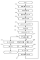
- FIG. It is a flowchart which shows the board
- FIG. It is a figure for demonstrating the method to measure the positional offset amount according to the curvature amount of the two board
- the substrate bonding method is a method of bonding a first substrate and a second substrate, and water or OH is formed on the surface of each bonding surface of the first substrate and the second substrate.
- a step of performing a hydrophilization treatment for adhering a contained substance, and bending the first substrate with respect to an outer peripheral portion of the bonding surface so that a central portion protrudes toward the second substrate In the state of abutting the bonding surface of the second substrate and the bonding surface of the second substrate with each other at the center portion, and in a state where the center portions are butted so as to maintain a constant distance,
- the flatness of the glass stage is about 5 ⁇ m, and by adjusting the parallelism to submicron and controlling the gap, it becomes possible to bring the gap closer to about 10 ⁇ m for the first time up and down without applying pressure. Further, it is preferable to perform bonding in a vacuum because it becomes easy to eliminate voids due to air entrainment even in a gap of 10 ⁇ m.
- the first substrate and the second substrate are arranged with the bonding surfaces facing each other between the hydrophilization treatment step and the bonding step, and the first substrate Between the first substrate and the second substrate so that the amount of positional deviation between the first substrate and the second substrate is small.
- a step of adjusting the relative position is arranged with the bonding surfaces facing each other between the hydrophilization treatment step and the bonding step, and the first substrate Between the first substrate and the second substrate so that the amount of positional deviation between the first substrate and the second substrate is small.
- the above bonding method further includes a step of measuring a positional shift amount between the first substrate and the second substrate during or after the bonding step.
- the outer peripheral portion of the first substrate and the second substrate are in contact with each other so that the central portions keep a constant distance. And the step of returning the deflection of the central portion of the first substrate, and the first substrate and the second substrate so that the positional deviation amount is small. Adjusting the relative position of the substrate and the second substrate, and the first substrate is centered with respect to the outer peripheral portion of the bonding surface until the amount of displacement is within an allowable error range. The process from the step of bending so that the portion protrudes toward the second substrate side to the step of adjusting the relative position between the first substrate and the second substrate is repeated.
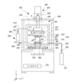
- FIG. 1 is a front view showing a schematic structure inside a substrate bonding apparatus 100 according to an embodiment of the present invention.
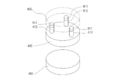
- FIG. 2 is a schematic perspective view showing the vicinity of the stage and the head.
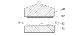
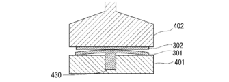
- FIG. 3 is a front sectional view showing the configuration of the stage holding the substrate.
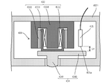
- FIG. 7 is a front sectional view showing another example of the protruding mechanism. In the following description, directions and the like are shown using an XYZ orthogonal coordinate system for convenience.
- the substrate bonding apparatus 100 includes a chamber 200, a substrate (second substrate) 301 that is an object to be bonded, and a substrate support unit 400 that supports the substrate (first substrate) 302 so as to face each other. , A position measuring means (positioning unit) 500 for measuring the relative positional relationship between the substrates 301 and 302, and a hydrophilic treatment means 600 for performing a surface activation process on the surfaces of the substrates 301 and 302 that are supported to face each other. And a controller (control unit) 700 that controls the operation of each unit of the substrate bonding apparatus 100.
- Examples of the substrates 301 and 302 include a glass substrate, an oxide substrate (for example, a silicon oxide (SiO 2 ) substrate, an alumina substrate (Al 2 O 3 )), a nitride substrate (for example, silicon nitride (SiN), and aluminum nitride. (AlN)).
- an oxide substrate for example, a silicon oxide (SiO 2 ) substrate, an alumina substrate (Al 2 O 3 )
- a nitride substrate for example, silicon nitride (SiN), and aluminum nitride. (AlN)
- the chamber 200 has a hollow box shape, and stages 401 and 402 of a substrate support means 400 described later are provided therein.
- the chamber 200 includes a vacuum pump 201 as a evacuation unit for evacuating the inside.
- the vacuum pump 201 is connected to the chamber 200 via the exhaust pipe 202.
- the exhaust pipe 202 is provided with an exhaust valve 203 that opens and closes the exhaust pipe 202.
- the exhaust pipe 202 is opened and the vacuum pump 201 is operated to discharge the gas in the chamber 200 to the outside through the exhaust pipe 202.
- the inside of the chamber 200 is depressurized and evacuated, and the atmosphere in the chamber 200 is brought into a vacuum or low pressure state.
- the exhaust valve 203 can adjust the exhaust flow rate in the exhaust pipe 202 by changing the opening / closing amount thereof, and can adjust the target vacuum degree in the chamber 200.
- ⁇ Distance measuring means for measuring the distance between the stage (second substrate holding unit) 401 holding the substrates 301 and 302 and the stage (first substrate holding unit) 402 before the step of bending the central portion of the substrate 301 or 302. (Not shown).
- the distance measuring means is preferably a device that can measure the distance between stages without contacting the stage, such as a laser distance meter.
- ⁇ Wafer thickness measuring means> Prior to the step of bending the central portion of the substrate 301 or 302, a wafer thickness measuring means (not shown) for measuring the thickness of each of the substrates 301 and 302 is provided.
- the wafer thickness measuring means is preferably capable of measuring the thickness of the substrate without contacting the substrate, such as a laser displacement meter.
- the wafer thickness is measured at three locations with a laser from above and below at the aligner position.
- the required thickness may be calculated by measuring the circumference or the entire surface.
- the distance between the substrates 301 and 302 can be calculated from the measurement results of the distance measuring means and the wafer thickness measuring means.
- the distance between the substrates 301 and 302 is the distance between the bonding surfaces of the substrates 301 and 302, and the stage (second substrate holding unit) 401 and the stage (first substrate holding) measured by the measurement means described above. Part) 402, and can be calculated as a distance obtained by subtracting the thickness of each of the substrates 301 and 302 measured by the wafer thickness measuring means.
- the substrate support means 400 includes a stage (second substrate holding unit) 401, a stage (first substrate holding unit) 402 for supporting the substrates 301 and 302, stage driving mechanisms 403 and 404 for moving the respective stages, and a substrate.
- Substrate heating means 420 for heating.
- Stages 401 and 402 are provided to face each other in the vertical direction (Z direction).
- the upper surface of the lower stage 401 is a support surface of the substrate 301.
- the lower surface of the upper stage 402 is a support surface of the substrate 302.
- the support surfaces of these stages 401 and 402 are arranged in parallel to each other.
- the stages 401 and 402 may have a holding mechanism such as a mechanical chuck, an electrostatic chuck, or a vacuum chuck on each support surface.
- This holding mechanism can switch between a fixed state of the substrates 301 and 302 to the support surface and an open state from the fixed state of the substrates 301 and 302 to the support surface.
- the lower stage 401 includes a stage drive mechanism 403.
- the stage drive mechanism 403 moves the lower stage 401 in the XY ⁇ direction within a horizontal plane orthogonal to the vertical direction (Z direction) in which the stage 401 and the stage 402 face each other.
- the upper stage 402 includes a Z-direction lifting drive mechanism 406 and a Z-axis rotation drive mechanism 407 as the stage drive mechanism 404.
- the stage drive mechanism 404 can further include an XY direction drive mechanism 405.
- the Z-direction lifting / lowering drive mechanism 406 moves the stage 402 in the Z direction, thereby moving the stages 401 and 402 closer to or away from each other along the Z direction. Further, the Z-direction lifting drive mechanism 406 brings the stages 401 and 402 close to each other to bring the bonded surfaces of the held substrates 301 and 302 into contact with each other, and further pressurizes the substrates 301 and 302 that are in contact with each other. be able to.
- the Z direction elevating drive mechanism 406 is provided with a pressure sensor 408 for measuring a force related to the Z axis.
- the pressure sensor 408 detects the pressure acting on the bonding surfaces of the substrates 301 and 302 that are pressed against each other by the Z-direction lift drive mechanism 406.
- a load cell can be used as the pressure sensor 408.
- the XY direction drive mechanism 405 can slide the stage 402 in the XY direction orthogonal to the Z direction where the stage 401 and the stage 402 face each other.
- a plurality of, for example, three projecting mechanisms 412 are provided in the vicinity of the outer periphery of the stage 402 at intervals in the circumferential direction. It has been.
- the protruding mechanisms 412 are independently extended and contracted in the Z direction. By these protrusion mechanisms 412, the distribution of force or pressure acting on the bonding surfaces of the substrates 301 and 302 is finely or accurately adjusted.
- a stage pressure sensor 411 is provided between each protrusion mechanism 412 and the XY direction drive mechanism 405.
- the operation of the protruding mechanism 412 is controlled by a control unit (not shown) according to the distribution of force or pressure acting on the bonding surfaces of the substrates 301 and 302 measured by the plurality of stage pressure sensors 411.
- the stage pressure sensor 411 and the protrusion mechanism 412 further finely adjust the distribution of pressure acting on the substrates 301 and 302 that are pressed against each other by the Z-direction lift drive mechanism 406, and extend over the joint surface. It can be a uniform or predetermined distribution.
- the operation of the Z-direction lifting drive mechanism 406 may be stopped based on the pressure generated on the bonding surface of the substrate 301 and the bonding surface of the substrate 302.
- the pressure generated on the bonding surface of the substrate 301 and the bonding surface of the substrate 302 exceeds a certain value, for example, when the direction in which the substrate is pressed against the counterpart substrate is positive, the pressure generated on the bonding surface of the substrate is When the value is greatly negative, it is considered that a force is working to reduce the distance between the substrates.
- the substrates may be deformed by a force generated in the X or Y direction. When such deformation occurs, positional displacement between the bonded substrates occurs.
- the Z-direction lifting drive mechanism 406 By maintaining the pressure generated on the bonding surface of the substrate 301 and the bonding surface of the substrate 302 at a constant force and stopping the operation of the Z-direction lifting drive mechanism 406 when this pressure exceeds a certain value, time passes. Then, the force to reduce the distance between the substrates is alleviated and returns to a certain value or less. When the pressure generated on the bonding surface of the substrates returns to a certain value or less, the Z-direction lift drive mechanism 406 can be re-driven again.
- the bonding surface of the substrate when the direction in which the substrate is pressed against the counterpart substrate is positive, the bonding surface of the substrate is maintained so that the pressure generated on the bonding surface of the substrate does not become a negative value. It is more preferable to maintain the pressure generated in As an example, when the lower limit value of the pressure generated on the bonding surface of the substrate is set to ⁇ 100 N, the operation speed is controlled or the operation is temporarily stopped when the detected pressure becomes ⁇ 150 N or less. . This can be applied both when the distance between the substrates is reduced and when the distance is removed.
- the pressure generated on the bonding surface of the substrates can be detected by a plurality of stage pressure sensors 411. Thereby, even if the substrate 301 or 302 has thickness variation or distortion, deformation due to pressure generated between the substrates can be suppressed.
- the pressure generated on the bonding surface of the substrate is maintained so as not to exceed a certain value. You may do it.
- the Z axis rotation drive mechanism 407 can rotate the stage 402 around the Z axis.
- the rotational drive mechanism 407 can control the rotational position ⁇ around the Z axis with respect to the stage 401 with respect to the stage 401, thereby controlling the relative positions of both substrates 301 and 302 in the rotational direction.
- control unit evacuates the atmosphere around the first substrate and the second substrate in the chamber so that the air can be bonded without voids. It becomes possible.
- the microelectrode portion made of Cu is subjected to CMP polishing in a dented state, and the insulating layer is first bonded at a low temperature of about 150 ° C. Then, there is a method in which the Cu electrodes are expanded by heating to about 350 ° C. to fill the gaps and diffusely bond Cu to each other.
- the gap between the Cu electrodes is filled with the atmosphere, and the surface of the Cu electrode is oxidized in the heating and expansion process, which is not preferable for joining.
- the air in the gap remains void as it has nowhere to go.
- SiO 2 which is a constituent material of the substrate, when a Cu electrode is included in the bonding surface, it is more preferable to apply heat and pressure in the bonding step.
- the gap is vacuumed by bonding in vacuum, so that oxidation can be suppressed and generation of voids can also be suppressed.
- the timing of evacuation it is possible to correct misalignment because there are many water molecules in the contact part by securing the atmospheric environment in the state where the center part is in contact, but it is a short time within a few minutes.
- the degree of vacuum is about several hundred Pa, it is possible to leave water molecules at the interface to some extent even if vacuuming is performed from the beginning.
- the entire surface can be secured in a vacuum atmosphere while interposing water molecules. If position correction after contact is not required, a vacuum may be drawn from the beginning.
- the alignment process between the first substrate and the second substrate may be performed before releasing the bent substrate or after evacuation.
- the time required for alignment is several seconds to several tens of seconds, and does not affect the bonding of the substrates.
- a stage 402 (or stage 401) not holding a substrate while holding only one of the substrates 301 (or substrate 302) before the step of bending the central portion of the substrate.
- a distance measuring means (not shown) for measuring the distance between the substrate and the held substrate.
- the distance measuring means is preferably a laser distance meter provided in the stage 402 (or stage 401), for example, and can measure the distance from the opposing stage or the upper surface of the substrate to the stage without contacting the opposing stage or substrate. .
- the distance between the substrates 301 and 302 can be calculated from the measurement results of the distance measuring means and the wafer thickness measuring means. For example, it is possible to obtain the inter-stage distance from the difference between the reflected light on the upper surface of the lower glass stage and the reflected light on the lower surface of the upper glass stage by introducing laser light from the upper part of the head side upper glass stage. When the wafer is on the lower stage, the distance between the lower surface of the upper glass stage and the upper surface of the lower wafer can be obtained.
- distance measuring means (not shown) is provided for measuring the distance between the bonding surfaces of the substrate 301 and the substrate 302 in a state where the substrate 301 and the substrate 302 are held on the stages 401 and 402. Also good. Specifically, a mode in which a distance measuring unit capable of measuring the distance between the bonding surfaces of the substrate 301 and the substrate 302 is inserted between the substrates to measure the distance between the substrates can be mentioned.
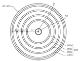
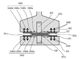
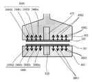
- a protruding mechanism 430 that can be projected and retracted toward the lower stage 401 side is built in the central portion of the support surface that supports the substrate 302.
- the protruding mechanism 430 can employ a cylinder structure or an electromagnetic mechanism. It is preferable that the protrusion mechanism 430 has at least a force that bends the substrate 302 and has a function of moving in a direction opposite to the protruding direction when receiving a force in a direction opposite to the protruding direction for a certain amount.
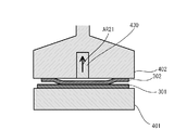
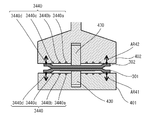
- the protruding mechanism 430 includes a pressing member 434 that presses the substrate 302, a voice coil motor 433, and a displacement sensor 435.
- the voice coil motor 433 includes a bottomed cylindrical coil bobbin 4331, a coil 4332 wound around the coil bobbin 4331, a magnet 4333 disposed to face the coil 4332, and a bottomed cylindrical part covering the outside of the coil 4332.
- a yoke 4334 configured from a bottom portion of the bottomed cylindrical portion and a protruding portion fitted inside the coil 4332.
- the pressing member 434 is fixed to the bottom of the coil bobbin 4331 of the voice coil motor 433.
- a yoke 4334 of the voice coil motor 433 is fixed to the stage main body 4021.
- the voice coil motor 433 when a current flows through the coil 4332, the coil bobbin 4331 moves along the cylinder axis direction.
- the pressing member 434 fixed to the coil bobbin 4331 moves in a direction protruding from the stage 402 or a direction immersing in the stage 402. Then, by controlling the magnitude of the current flowing through the coil 4332, the pressure applied to the substrate 302 by the pressing member 434 fixed to the coil bobbin 4331 can be controlled.
- the pressing member 434 includes a protruding portion 4341 that protrudes from the stage main body 4021 to the outside, and a flat base portion 4342 that is formed integrally with the protruding portion 4341.
- the displacement sensor 435 is comprised, for example from an eddy current type displacement sensor, and measures the distance LH between the detection part 435a and the base part 4342 of the press member 434.
- FIG. The substrate bonding apparatus 100 can execute position control of the pressing member 434 fixed to the coil bobbin 4331 based on the distance LH measured by the displacement sensor 435.
- the protruding mechanism 430 uses the voice coil motor 433, pressure control when the pressing member 434 presses the substrate 302 and position control of the pressing member 434 are possible.
- the substrate bonding apparatus 100 when the substrate bonding apparatus 100 performs pressure control while pressing the substrate 302 with the pressing member 434, if the position of the pressing member 434 is out of a preset range, the substrate bonding apparatus 100 controls the pressing member 434. By switching to position control, the pressing member 434 can be returned to a preset range. As described above, the substrate bonding apparatus 100 can combine pressure control and position control of the pressing member 434.
- a protrusion mechanism it may have a cylinder structure, for example, and can change a pressurizing force by changing the air pressure supplied in a cylinder.
- a protrusion mechanism it is an electromagnetic coil type
- the projecting mechanism is pushed down by bringing the substrates closer to each other by the vertical movement axis between the substrates, for example, the Z axis in this embodiment, to bring the distance between each substrate of the head or stage from the bent state.
- the contact area can be increased from the center to the outer periphery, following the other flat substrate.
- the speed of wetting and spreading can be controlled by numerically controlling the distance between the substrates.
- the wetting speed is different, and the conventional method of inserting the claw between the wafers and pulling it out and dropping it naturally causes voids, so speed control is an effective method.
- the distance from the bottom surface of each substrate to the center portion can be expanded and contracted according to the Z-axis movement of the head.
- the contact area can be increased to the outer peripheral portion by moving the outer peripheral portion closer while maintaining the same upper and lower sides.
- the alignment mark position of the substrate on one side is also shifted inward, resulting in poor alignment accuracy and distortion during joining.
- the alignment mark position can be brought to the same position, and bonding can be performed without causing distortion at the time of joining, which is an effective method compared to a conventional one-side protruding mechanism.
- the amount of protrusion that required 20 ⁇ m on one side can be accommodated at 10 ⁇ m on both sides, resulting in less distortion.
- this method is particularly effective in the field of simultaneously bonding a microelectrode called a hybrid bonding that requires submicron accuracy and a peripheral insulating layer, for example, a CMOS image sensor, a memory, an arithmetic element, and a MEMS.
- both end marks of the substrate are read with an image processing device, and the amount of displacement is corrected and then moved for correction. If water molecules exist at the interface between the two substrates and the applied pressure is small, although the correction movement can be performed in the contact state, when the contact area is large, the protrusion mechanism may be pulled back once to provide a correction movement with a gap between both substrates. Further, it is possible to provide a gap by moving the Z-axis without changing the protruding mechanism. Moreover, a clearance gap can also be provided using both.
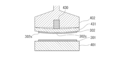
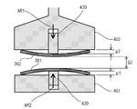
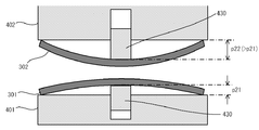
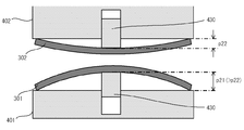
- FIG. 5 is a front sectional view showing a state in which the substrate 302 is bent by the protruding mechanism 430 provided in the stage 402.
- the protrusion mechanism 430 when the protrusion mechanism 430 is protruded from the stage 402, the outer peripheral portion 302s of the substrate 302 receives a downward force due to its own weight so that the central portion 302c of the substrate 302 protrudes upward.
- “protruding mechanism 430 protrudes from stage 402” means that the pressing member 434 of the protruding mechanism 430 protrudes from the stage 402 in detail.
- the pressing by the protruding mechanism 430 is released, or when the substrate 302 is abutted against the opposing substrate 301 and receives a force exceeding a certain level, the substrate 302 is restored to the original flat plate shape.
- the top portion 430a that contacts the substrate of the protruding mechanism 430 may have a curved shape as shown in FIG. Thereby, a board
- the bonding of the central portion 301 c of the substrate 301 is performed separately from the method for defining the bonding position as described above. It is preferable to reduce the distance between the outer peripheral portion 301 s of the substrate 301 and the outer peripheral portion 302 s of the substrate 302 by the protruding distance of the surface with respect to the bonding surface of the outer peripheral portion 301 s of the substrate 301.
- the distance between the outer peripheral portion 301 s of the substrate 301 and the outer peripheral portion 302 s of the substrate 302 is reduced by a distance equivalent to the protruding distance of the protruding mechanism 430.
- the bonding position can be determined from the pushing amount of the protruding mechanism 430 measured by the above-described displacement sensor 435.
- the detection value of the displacement sensor 435 at the abutting position is stored, and the protrusion amount can be calculated from the difference from the detection value of the displacement sensor 435 when protruding.
- the vertical protrusion amount may be added.
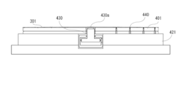
- the stages 401 and 402 may have a holding mechanism 440 such as a mechanical chuck, an electrostatic chuck, or a vacuum chuck on each support surface.
- This holding mechanism can switch between a fixed state of the substrates 301 and 302 to the support surface and an open state from the fixed state of the substrates 301 and 302 to the support surface.
- the holding mechanism may be divided into a plurality of regions on the surfaces of the stages 401 and 402 as shown in FIG.
- two holding mechanisms an outer holding mechanism 440a and an inner holding mechanism 440b
- the outer holding mechanism 440a and the inner holding mechanism 440b can be controlled independently, and the inner holding mechanism 440b is opened while the outer holding mechanism 440a holds the outer peripheral portion of the substrate, and the Z-axis is formed in the central portion of the substrate. It is possible to avoid receiving force in the direction.
- holding mechanisms 440 When a plurality of holding mechanisms 440 are provided, for example, holding mechanisms having different principles and functions, such as an electrostatic chuck and a vacuum chuck, may be used in combination.
- electrostatic chuck electrodes and vacuum chuck suction grooves may be provided alternately in the radial direction of the stage.
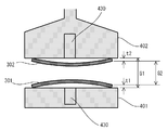
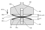
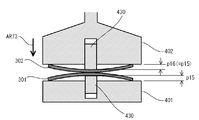
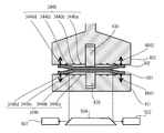
- a mechanism similar to the protruding mechanism 430 may be provided on the lower stage 401 side. As shown in FIG. 7, by adopting a configuration in which the substrates 301 and 302 are bent by both the stages 401 and 402, the amount of bending of the substrate is reduced, and the substrate can be aligned with less error.
- the lower substrate 301 When the lower substrate 301 is bent, it is preferable to hold only the outer peripheral portion 301 s of the substrate 301. In this case, it is preferable that only the outer peripheral portion 301s of the substrate 301 is held by the outer holding mechanism 440a because the substrate bends to a desired shape even if the force of pressing the substrate by the protruding mechanism 430 is weak.
- the suction groove provided on the stage may be separated by the location of the substrate.
- the suction groove for holding the peripheral portion of the substrate and the suction groove for holding the central portion of the substrate may be separated and each may operate separately. Thereby, only the outer peripheral part of a board
- the central part is first vacuum-adsorbed, and when it bends, it breaks down to the atmospheric pressure.
- the substrate can be easily peeled off by releasing pressurized air for a few seconds.
- the substrate is difficult to peel off at the mirror surface, it is possible to make it easy to peel off while maintaining the height accuracy by intentionally roughening the holding portion contact surface.
- the bonded substrate assembly may have variations in warpage and thickness.
- the entire surface of the lower stage 401 is again vacuum-sucked to reduce warpage and thickness variations in the substrate assembly. be able to.
- the holding mechanism 440 when the holding mechanism 440 is of the electrostatic chuck type, the holding mechanism is divided into a plurality of regions on the surfaces of the stages 401 and 402 as shown in an example in FIG. May be.
- two different patterns that can be individually controlled are provided, that is, the outer holding mechanism 440a and the inner holding mechanism 440b.
- the outer holding mechanism 440a and the inner holding mechanism 440b can be controlled independently, and the inner holding mechanism 440b is opened while the outer holding mechanism 440a holds the outer peripheral portion of the substrate, and the Z-axis is formed in the central portion of the substrate. It is possible to avoid receiving force in the direction.
- the vacuum suction groove in the central portion is used together to break the vacuum to atmospheric pressure.
- the substrate can be easily peeled off by releasing pressurized air for a few seconds.
- the holding mechanism may be divided into three, and one or more grooves may be inserted between the central portion and the outer peripheral portion to provide an air release layer.
- both the leaks are absorbed by the air release layer between the central part and the central part even when the central part releases pressurized air while maintaining the vacuum at the outer peripheral part. Even if the holding is peeled off or air is released, it is possible to prevent the central portion from being bent due to being sucked by the outer peripheral portion, which is effective.
- the adsorbing part and the atmosphere releasing part are not limited to the grooves, and may be configured to support a plurality of points in the plane.
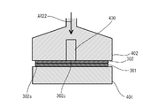
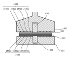
- a support plate that supports the substrate 302 may be provided with a pressing plate 431 having a thin plate shape and flexibility.
- the pressing plate 431 may have a holding mechanism (not shown) such as a vacuum suction method, a mechanical chuck, or an electrostatic chuck on a support surface that supports the substrate 302.
- the pressing plate 431 is elastically deformed, and the center portion 431c is bent so as to protrude downward.
- the pressing plate 431 is bent so as to protrude downward, whereby the central portion 302c of the substrate 302 on which the outer peripheral portion 302s is held by the holding mechanism (not shown) is directed toward the lower stage 401. Pressed. Then, the substrate 302 is elastically deformed along the pressing plate 431, and is bent so that the central portion 302c is convex downward with respect to the outer peripheral portion 302s.
- the entire substrate 302 is pressed and bent, so that the substrate 302 can be prevented from being distorted.
- the pressing by the protruding mechanism 430 is released, the substrate 302 is restored to the original flat shape.
- the substrate heating means 420 includes heaters 421 and 422 built in stages 401 and 402.
- the heaters 421 and 422 are configured to generate Joule heat with, for example, an electric heater.
- the heaters 421 and 422 conduct heat through the stages 401 and 402 to heat the substrates 301 and 302 supported by the stages 401 and 402.
- Stages 401 and 402 and heaters 421 and 422 may be formed of separate members.
- the stages 401 and 402 including the holding mechanism 440 may be overlapped with the heaters 421 and 422 including the heater wiring. An example is shown in FIG.
- It can also be joined as it is by heating with a heater of a joining device, but it can also be joined by taking it out in a bonded state and annealing it at 150 ° C. for several hours in a batch furnace or hot plate in a free state without pressure. .
- the position measuring unit 500 measures the relative positional relationship between the substrates 301 and 302.
- the position measuring means 500 includes a window 503 formed in the chamber 200, a light source (not shown), a plurality of cameras 501 and 502, and mirrors 504 and 505.
- Light emitted from a light source (not shown) passes through mirrors 504 and 505 and a window 503 and strikes portions (not shown) provided with marks on the substrates 301 and 302.
- the cameras 501 and 502 capture an image of reflected light from a portion (not shown) provided with marks on the substrates 301 and 302 through a window 503 and mirrors 504 and 505.
- the cameras 501 and 502 each have a coaxial illumination system.
- the light source may be provided on the upper side of the stage 401 or may be provided so as to emit light from the cameras 501 and 502 side so as to travel along the optical axis.
- a wavelength region for example, the substrate can be made of silicon that passes through portions where the marks are provided on the substrates 301 and 302 and portions where the light should pass such as both stages. If it is, infrared light) is used.
- infrared transmission recognition is performed with the bonding surface of the substrate 301 and the bonding surface of the substrate 302 maintained at a distance that maintains the non-bonded state between the entire surfaces. It can be carried out.
- the relative positions of the substrates arranged opposite to each other may be measured by the cameras provided on the stages 401 and 402 side.
- the substrate bonding apparatus 100 can measure and align the relative positions of the substrates 301 and 302 using the position measuring means 500, the driving mechanisms 403 to 407, and the controller 700 connected thereto.
- the locations where light for measurement passes are defined on the substrates 301 and 302, and a mark is attached here to reflect, block or refract part of the passing light.
- the alignment mark appears dark in the captured bright field image.
- the reflected light from the alignment mark is received, the mark appears bright in a dark image.
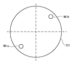
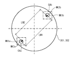
- a plurality of alignment marks are provided on the substrate, for example, at two opposite corners of the substrate. Thereby, the absolute position of the substrate 301 or 302 can be specified from the positions of the plurality of alignment marks.
- corresponding alignment marks are attached to corresponding portions of the substrates 301 and 302, for example, positions overlapping in the Z direction during bonding. Both alignment marks on the substrates 301 and 302 are observed within the same field of view, and the relative displacement amounts in the X and Y directions are measured. By measuring the relative displacement amounts in the X direction and the Y direction at a plurality of locations, the relative displacements ( ⁇ X, ⁇ Y, ⁇ ) of the substrates 301 and 302 in the X direction, Y direction, and ⁇ direction are calculated. Can do.
- the measurement operation of the positional deviation amount in the position measuring means 500 can be executed when the substrates 301 and 302 are in a non-contact state or a contact state.
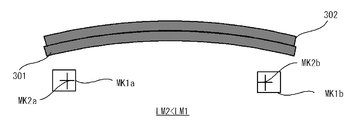
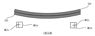
- the substrate 301 is provided with two alignment marks (first alignment marks) MK1a and MK1b for alignment. Further, as shown in FIG. 11, the substrate 302 is also provided with two alignment marks (second alignment marks) MK2a and MK2b for alignment. Images obtained by photographing the alignment marks MK1a, MK1b, MK2a, and MK2b relating to both the substrates 301 and 302 are as shown in FIG. 12, for example.
- the position measuring means 500 uses both images (image data) GA relating to transmitted light and reflected light of illumination light emitted from the respective coaxial illumination systems of the cameras 501 and 502 in a state where both the substrates 301 and 302 face each other.
- the positions of the substrates 301 and 302 can also be recognized.
- the positional deviation measurement for the alignment operation (fine alignment operation) of both the substrates 301 and 302 is performed by the cameras 501 and 502 with two sets of alignment marks (MK1a and MK2a) attached to both the substrates 301 and 302. ) And (MK1b, MK2b) are simultaneously recognized.
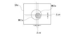
- the position measuring means 500 acquires an image GAa including alignment marks MK1a and MK2a and an image GAb including alignment marks MK1b and MK2b as shown in FIG. 12, and attaches them to both substrates 301 and 302 based on the images GAa and GAb.
- the position of each set of marks (MK1a, MK2a), (MK1b, MK2b) is recognized.
- the controller 700 Based on the relative positions of the recognized marks (MK1a, MK2a) and (MK1b, MK2b), the controller 700 detects the amount of misalignment between the marks (MK1a, MK2a) and (MK1b, MK2b) as shown in FIG. ⁇ xa, ⁇ ya) can be obtained.
- FIG. 12 shows a state in which each set of marks (MK1a, MK2a), (MK1b, MK2b) is in a desired position with their centers overlapping each other
- FIG. 13 shows a set of marks (MK1a, MK2a). ) Shows a state of being deviated from the desired position.
- each image GAa, GAb (image GAa is shown in FIG. 13) is positioned for each set of marks based on the geometric relationship of the marks on the substrates 301, 302. Deviation amounts ( ⁇ xa, ⁇ ya) and ( ⁇ xb, ⁇ yb) are obtained.
- the controller 700 detects X from the desired positions of the substrates 301 and 302 based on the positional deviation amounts ( ⁇ xa, ⁇ ya) and ( ⁇ xb, ⁇ yb) of the two sets of marks (MK1a, MK2a) and (MK1b, MK2b).
- a relative deviation amount ⁇ D (specifically, ⁇ x, ⁇ y, ⁇ ) in the direction, the Y direction, and the ⁇ direction is calculated.
- the relative deviation amount ⁇ D corresponds to the correction movement amount by the subsequent correction movement.
- the controller 700 finally adjusts the substrates 301 and 302 by a correction amount ⁇ D ( ⁇ x, ⁇ y, ⁇ ) corresponding to the relative deviation amount ⁇ D ( ⁇ x, ⁇ y, ⁇ ) between the substrates 301 and 302.
- the path of the correction movement that moves is calculated.
- the controller 700 instructs the drive mechanisms 403 to 407 of the stages 401 and 402 to move both the substrates 301 and 302 according to the calculated correction path.
- the correction movement is performed so that the relative deviation amount ⁇ D is zero or reduced.
- stage driving is performed so that the stage 402 that supports the substrate 302 finally moves by a correction amount ( ⁇ D) with respect to the stage 401 that supports the substrate 301.
- the mechanisms 403 and 404 are controlled.
- the stage driving mechanisms 403 and 404 drive the two translational directions (X direction and Y direction) and the rotational direction ( ⁇ direction) and the stage 402 in accordance with an instruction from the controller 700.
- the relative displacement is made, and the positional deviation amount ⁇ D is corrected.
- the correction movement is considered to be performed in a state where the bonding surfaces of the substrates are separated from each other and in a state where they are in contact with each other. Each correction movement will be described below.
- the positional deviation amount ⁇ D (specifically, ⁇ x, ⁇ y, ⁇ ) in the plane (horizontal plane) perpendicular to the vertical direction (Z direction) is measured, and an alignment operation (correction is performed for the positional deviation amount ⁇ D). Fine alignment operation) is executed.
- the present invention is not limited to this.
- the images GAa and GAb may be sequentially captured and acquired by moving one camera in the X direction and / or the Y direction.
- each set of marks was imaged simultaneously on the same optical axis, the present invention is not limited to this.
- two sets (a total of four) cameras arranged for the respective substrate positions may be used. If the positional relationship of the optical axes of the cameras is known, each of the corresponding marks (MK1a, MK2a) is imaged by each camera and then combined to obtain a substantially joined position in the translation direction. It can be moved and positioned.
- the substrate bonding apparatus 100 includes hydrophilic treatment means 600.
- the hydrophilic treatment means 600 of the substrate bonding apparatus 100 shown in FIG. 1 includes an activation processing unit 610 that activates the bonding surfaces of the substrates 301 and 302, and a hydrophilic treatment that hydrophilizes the activated bonding surfaces of the substrates 301 and 302. And a processing unit 620.
- the activation processing unit 610 removes the surface layer by causing a phenomenon (sputtering phenomenon) in which particles having a predetermined kinetic energy collide with each other in a vacuum to physically blow off the material forming the bonding surface. be able to.
- a phenomenon sputtering phenomenon
- the surface activation treatment not only the surface layer is removed to expose the nascent surface of the substance to be bonded, but also the crystal structure near the exposed nascent surface is collided with particles having a predetermined kinetic energy. It is thought that there is also an effect of disturbing and amorphizing.
- the amorphized new surface has a higher surface area at the atomic level and a higher surface energy, it is considered that the number of hydroxyl groups (OH groups) per unit surface area to be bonded in the subsequent hydrophilization treatment is increased.
- OH groups hydroxyl groups
- the hydrophilization treatment following the surface activation treatment according to the bonding method of the invention is fundamentally different from the conventional hydrophilization treatment in this respect.
- atoms in the vicinity of the nascent new surface that are disordered due to the crystal structure are easily diffused with relatively low thermal energy during the heat treatment during the main bonding, realizing a main bonding process at a relatively low temperature. I think it can be done.
- a rare gas or an inert gas such as neon (Ne), argon (Ar), krypton (Kr), or xenon (Xe) can be used. Since these rare gases have a relatively large mass, it is considered that a sputtering phenomenon can be efficiently generated and the crystal structure of the nascent surface can be disturbed.
- oxygen ions As the particles used for the surface activation treatment, oxygen ions, atoms, molecules, and the like may be employed. By performing the surface activation treatment using oxygen ions or the like, it is possible to cover the nascent surface with an oxide thin film after removing the surface layer.
- the oxide thin film on the nascent surface is believed to enhance the efficiency of hydroxyl (OH) group bonding or water attachment in subsequent hydrophilization treatments.
- OH hydroxyl
- the oxide thin film formed on the nascent surface is relatively easily decomposed during the heat treatment in the main bonding.
- the kinetic energy of the particles colliding with the surface-activated joint surface is 1 eV (electron volts) to 2 keV. It is considered that the above kinetic energy efficiently causes a sputtering phenomenon in the surface layer.
- a desired value of kinetic energy can also be set from the above kinetic energy range according to the thickness of the surface layer to be removed, the properties such as the material, the material of the new surface, and the like.
- a predetermined kinetic energy can be given to the particles that collide with the surface-activated joint surface by accelerating the particles toward the joint surface.
- a predetermined kinetic energy can be given to the particles using a plasma generator.
- a plasma generator By applying an alternating voltage to the bonding surface of the substrate, a plasma containing particles is generated around the bonding surface, and the cations of the ionized particles in the plasma are accelerated toward the bonding surface by the voltage.
- given kinetic energy is given. Since the plasma can be generated in an atmosphere with a low degree of vacuum of about several pascals (Pa), the vacuum system can be simplified and the steps such as evacuation can be shortened.
- the particle beam source operates in a relatively high vacuum, such as 1 ⁇ 10 ⁇ 2 Pa (pascal) or 1 ⁇ 10 ⁇ 5 Pa or less, so unnecessary oxidation or renewal of the regenerated surface after the surface activation treatment is performed. Impurities can be prevented from adhering to the surface. Furthermore, since the particle beam source can apply a relatively high acceleration voltage, high kinetic energy can be imparted to the particles. Therefore, it is considered that the removal of the surface layer and the amorphization of the new surface can be performed efficiently.
- the plasma generator operates at 100 W and generates plasma of nitrogen (N 2 ), oxygen (O 2 ), and argon (Ar) as a hydrophilic treatment, and this plasma is applied to the bonding surface for about 30 seconds. If used to irradiate, treatment for hydrophilization can be performed.
- the plasma generator may be installed separately from the bonding apparatus so as to connect in the vacuum or handle the atmosphere once.
- Neutral atoms or ions can also be used for the particles used for surface activation.
- a predetermined kinetic energy can be given to the particles using a particle beam source such as a neutral atom beam source or an ion beam source (ion gun) disposed at a position separated from the bonding surface.
- the particles to which a predetermined kinetic energy is applied are emitted from the particle beam source toward the bonding surface of the substrate.
- nitrogen (N 2 ), oxygen (O 2 ), argon (Ar), or the like may be used as a reaction gas.
- a fast atom beam source As the neutral atom beam source, a fast atom beam source (FAB, Fast Atom Beam) can be used.
- FABs Fast atom beam sources
- FABs typically generate a plasma of gas, apply an electric field to the plasma, extract the cations of particles ionized from the plasma, and pass them through an electron cloud. It has the composition which becomes.
- the power supplied to the fast atom beam source (FAB) may be set to 1.5 kV (kilovolt), 15 mA (milliampere), or 0.1 W You may set to the value between (watt) and 500W (watt).
- a fast atom beam source FAB
- a fast atom beam source FAB
- 100 W watts
- 200 W watts
- a fast atom beam of argon (Ar) for about 2 minutes the oxide, contaminants, etc. (surface) Layer) can be removed to expose the nascent surface.
- the ion beam source (IG) may be used to operate at 110 V, 3 A, for example, to accelerate argon (Ar) and irradiate the bonding surface for about 600 seconds.
- the particles used for surface activation may be neutral atoms or ions, may be radical species, and may be a particle group in which these are mixed.
- the removal rate of the surface layer can vary. Therefore, it is necessary to adjust the treatment time required for the surface activation treatment. For example, the presence of oxygen and carbon contained in the surface layer is confirmed using surface analysis methods such as Auger Electron Spectroscopy (AES, Auger Electron Spectroscopy) and X-ray Photoelectron Spectroscopy (XPS, X-ray Photo Electron Spectroscopy). You may employ
- Auger Electron Spectroscopy Auger Electron Spectroscopy
- XPS X-ray Photoelectron Spectroscopy
- the irradiation time of the particles may be set longer than the time necessary for removing the surface layer and exposing the new surface.
- the lengthening time may be set to 10 to 15 minutes, or 5% or more of the time required for removing the surface layer and exposing the new surface.
- the time for making the bonding surface amorphous in the surface activation treatment may be appropriately set according to the type and nature of the material forming the bonding surface and the irradiation conditions of particles having a predetermined kinetic energy.
- the kinetic energy of the irradiated particles is set to be 10% or more higher than the kinetic energy necessary for removing the surface layer and exposing the new surface. Good.
- the kinetic energy of the particles for making the bonding surface amorphous in the surface activation treatment may be appropriately set depending on the type and property of the material forming the bonding surface and the irradiation conditions of the particles.
- the “amorphized surface” or “surface with disordered crystal structure” specifically includes an amorphous layer whose presence has been confirmed by measurement using a surface analysis technique or a layer with a disordered crystal structure, This is a conceptual term that expresses the state of the crystal surface assumed when the particle irradiation time is set to be relatively long or the particle kinetic energy is set to be relatively high. It includes a surface in which the presence of an amorphous layer or a surface having a disordered crystal structure is not confirmed by the measurement used. Also, “amorphize” or “disturb the crystal structure” conceptually represents the operation for forming the amorphized surface or the surface in which the crystal structure is disturbed.
- the Si particle beam can be emitted simultaneously with the Ar particle beam by interposing a material containing Si in the casing.
- the interface is doped with Si, an interface with more active Si is formed, and more OH groups are formed when the hydrophilic treatment is performed, thereby increasing the strength. This is particularly effective for increasing the bonding strength in a vacuum.
- the bonding strength of the Si wafer with oxide film in vacuum is 1.5 J / m 2 without the Si plate.
- the strength is increased to a bulk breakdown of 2.5 J / m 2 or more.
- the particle beam treatment by FAB or IG may be transported in the atmosphere or connected as a separate device in addition to being arranged in the joining device.
- the hydrophilic treatment unit 620 bonds a hydroxyl group (OH group) to the bonding surface of the substrates 301 and 302 cleaned or activated by the activation processing unit 610.
- the hydrophilic treatment by the hydrophilic treatment unit 620 is performed by supplying water (H 2 O) around the bonding surfaces of the surface activated substrates 301 and 302 in the chamber 200. Therefore, the hydrophilization processing unit 620 includes a water gas generator 621, a valve 622, and a water gas supply pipe 623.
- the supply of water is performed by introducing, for example, gaseous water (H 2 O) into the atmosphere around the surface activated bonding surface.
- Gaseous water is generated by bubbling the argon (Ar) carrier gas through the water gas generator 621 in the form of bubbles.
- Gaseous water is mixed with the carrier gas, controlled to a desired flow rate by the valve 622, and introduced into the chamber 200 through the water gas supply pipe 623.
- the carrier gas at this time is not limited to argon (Ar), and may be nitrogen (N 2 ), helium (He), oxygen (O 2 ), or the like.
- water may be water vapor, or may be introduced into the chamber 200 by spraying liquid water in a mist form.
- radicals, ionized OH groups, or the like may be attached.
- the substrate may be cooled in order to allow water to adhere to the bonding surface of the substrate, and the bonding apparatus of this embodiment may include a cooling device for this purpose. Even when the environmental humidity is about 50%, the humidity of the substrate surface can be raised to about 85 to 100% by cooling the substrate.
- water In the hydrophilization treatment, water, hydroxide, hydroxide ion (OH ⁇ ), hydroxyl radical ( ⁇ OH), or a substance represented by OH is formed on the bonding surface that has been subjected to the surface activation treatment.
- OH-containing substances such as ions and radicals (hereinafter also referred to as “water”) are attached to form a layer terminated with a hydroxyl group (OH group) (M—OH) on the bonding surface. Is done.
- water or OH-containing substance the substance to be attached to the bonding surface subjected to the surface activation treatment
- water etc. these are collectively called “water etc.”, or more simply “water”.
- water H 2 O
- the hydrophilization process can be controlled by controlling the humidity of the atmosphere around the bonding surfaces of the surface-activated substrates 301 and 302.
- the humidity may be calculated as relative humidity, may be calculated as absolute humidity, or other definitions may be employed.
- the introduction of water is preferably controlled so that the relative humidity in the atmosphere around at least one or both of the joint surfaces of both substrates is 10% to 90%.
- the total pressure in the chamber is 9.0 ⁇ 10 4 Pa (Pascal), that is, 0.89 atm (Atom )
- the amount of gaseous water in the chamber is 8.6 g / m 3 (gram / cubic meter) or 18.5 g / m 3 (gram / cubic meter) in absolute volume humidity, 23 ° C. (23 degrees Celsius)
- the relative humidity can be controlled to be 43% or 91%, respectively.
- the atmospheric concentration of oxygen (O 2 ) in the chamber may be 10%.
- air outside the chamber having a predetermined humidity may be introduced.
- air it is preferable that the air passes through a predetermined filter in order to prevent unwanted impurities from adhering to the bonding surface.
- water (H 2 O) molecules or clusters may be accelerated and radiated toward the bonding surface.
- the acceleration of the water (H 2 O) may be used, such as particle beam source used for the surface activation treatment.
- a mixed gas of carrier gas and water (H 2 O) generated by bubbling or the like is introduced into the particle beam source, thereby generating a water particle beam, and on the joint surface to be hydrophilized. It can be irradiated towards.
- the hydrophilization treatment may be performed by converting water molecules into plasma and bringing it into contact with the joint surface in an atmosphere near the joint surface.
- water washing may be performed as a hydrophilic treatment to remove particles (contaminated particles).
- hydrophilic treatment You may perform the same kind or different kind of hydrophilic treatment in multiple times. Also, As part of the hydrophilization treatment, Or after hydrophilization treatment Water molecules may be forced to adhere to the joint surface. This The amount of water molecules on the joint surface can be increased or controlled. Moreover, Thereby, the critical pressure can be adjusted.
- the surface where the surface activation treatment and the hydrophilization treatment have been performed is bonded with water molecules intervening as described above, but hydrogen bonds between OH groups can be achieved by removing water molecules. By attracting each other, a relatively strong temporary joint is formed. Further, since a bonding interface including hydrogen and oxygen is formed, hydrogen and oxygen are released to the outside of the bonding interface by the heat treatment in the main bonding, and a clean bonding interface can be formed.
- the method of applying pressure and the method of heating were shown as the bonding method.
- pressure exceeding the critical pressure for example, by pressurizing at 10 MPa
- water molecules are pushed to join between OH groups. Change.
- heat water molecules are removed from the interface and changed to bonding between OH groups. After that, by continuing the heating, the hydrogen bond is changed to the covalent bond, and a transition is made to a strong main junction state.
- the same temporary bonding state can be maintained by bonding after leaving water in a vacuum for a long time to blow off water molecules.
- Bonding can be performed by applying pressure from a bonding state in which water molecules intervene, or bonding in a vacuum. Thereafter, heating can be used in combination in order to make a transition to strong bonding. It is also possible to make a transition to strong bonding from the beginning by heating.
- heating involves thermal expansion of the substrate, it is effective to heat in a state where the substrate is temporarily bonded by pressurization or bonding in vacuum.
- Oxide may be formed on the joint surface by the hydrophilic treatment.
- a hydroxyl (OH) group directly on the new surface without adhesion of impurities by continuously adhering water, etc.
- water molecules adhere to the hydroxyl (OH) group.
- this oxide is relatively controlled (for example, a thickness of several nm or several atomic layers or less), it does not particularly deteriorate electrical characteristics.
- heat treatment after pasting it can be absorbed in the metal material, or can be eliminated or reduced by escaping from the bonding interface as water. Therefore, in this case, it is considered that there is almost no practical problem in the conductivity through the bonding interface with the substrate.
- a measurement process for measuring the inter-stage distance and the wafer thickness is executed (step S100).
- the measurement process is performed before the process of bending the central portion of the substrate.
- the substrate is held in a state where only one of the substrates 301 (or the substrate 302) is held before the step of bending the central portion of the substrate.
- the distance between the stage 402 (or stage 401) not held and the held substrate may be measured, and the distance between the substrates 301 and 302 may be calculated from the measurement result and the measurement result of the wafer thickness measuring means. .
- the distance between the bonding surfaces of the substrate 301 and the substrate 302 may be measured in a state where the substrate 301 and the substrate 302 are held on the stages 401 and 402.
- a hydrophilic treatment process is executed (step S101).
- the hydrophilic treatment is performed on the surfaces of the bonding surfaces of the substrate 301 and the substrate 302.
- the hydrophilic treatment process first, as shown in FIG. 3, the substrate 301 is held by a holding mechanism (not shown) of the stage 401 of the substrate bonding apparatus 100, and the outer periphery of the substrate 302 is held by the holding mechanism (not shown) of the stage 402. The part 302s is held. In this state, the substrate 301 and the substrate 302 are opposed to each other with their bonding surfaces being separated from each other.
- the chamber 200 is opened to the atmosphere, and the atmosphere is introduced into the atmosphere around the substrates 301 and 302 in the chamber 200.
- the bonding surfaces of the substrates 301 and 302 are activated by any of the activation treatment methods described above.
- plasma-processed argon (Ar) is caused to collide with the bonding surfaces of the substrates 301 and 302 to perform a sputtering process.
- the surface layer of the bonding surfaces of the substrates 301 and 302 is removed, and the nascent surface of the substance to be bonded is exposed, and the crystal structure in the vicinity of the exposed nascent surface is disturbed and becomes amorphous.
- the activated bonding surfaces of the substrates 301 and 302 are hydrophilized by any of the hydrophilic treatment methods described above.
- the water gas generator 621 generates gaseous water, and the generated gaseous water is introduced into the chamber 200 through the water gas supply pipe 623 together with the carrier gas.
- a hydrophilic treatment is performed by attaching an OH-containing substance such as water to the bonding surfaces of the substrates 301 and 302 that have been subjected to the surface activation treatment, the bonding surfaces are terminated with hydroxyl groups (OH groups) (M-OH). ) Is formed.
- step S100 interstage distance and wafer thickness measurement step
- step S101 hydrophilization treatment step
- an alignment process of the substrates 301 and 302 is executed (step S102).
- this alignment step alignment between the substrate 301 and the substrate 302 is performed. This is related to transmitted light and reflected light of illumination light emitted from the respective coaxial illumination systems of the cameras 501 and 502 in the position measuring means 500 in a state where the substrate 301 in a bent state and the substrate 302 face each other.
- the image (image data) GA the positions of both the substrates 301 and 302 are recognized.
- the position measuring means 500 acquires the image GAa including the alignment marks MK1a and MK2a and the image GAb including the alignment marks MK1b and MK2b (FIG.
- each set of marks (MK1a, MK2a), (MK1b, MK2b) is recognized. Based on the relative positions of the recognized marks (MK1a, MK2a), (MK1b, MK2b), the controller 700 determines the amount of positional deviation ( ⁇ xa, ⁇ ya) ( ⁇ xb) between the marks (MK1a, MK2a), (MK1b, MK2b). , ⁇ yb) is obtained (FIG. 13).
- the controller 700 detects X from the desired positions of the substrates 301 and 302 based on the positional deviation amounts ( ⁇ xa, ⁇ ya) and ( ⁇ xb, ⁇ yb) of the two sets of marks (MK1a, MK2a) and (MK1b, MK2b).
- a relative deviation amount ⁇ D (specifically, ⁇ x, ⁇ y, ⁇ ) in the direction, the Y direction, and the ⁇ direction is calculated.
- the controller 700 finally adjusts the substrates 301 and 302 to the correction amounts ⁇ D ( ⁇ x, ⁇ y, and ⁇ ) corresponding to the relative deviation amounts ⁇ D ( ⁇ x, ⁇ y, ⁇ ) between the substrates 301 and 302. )
- the controller 700 instructs the drive mechanisms 403 to 407 of the stages 401 and 402 to move both the substrates 301 and 302 according to the calculated correction path.
- the stage driving mechanisms 403 and 404 drive the stage 402 in two translational directions (X direction and Y direction) and a rotational direction ( ⁇ direction) in accordance with an instruction from the controller 700, whereby both substrates 301 and 302 are driven. Are relatively moved, and the positional deviation amount ⁇ D is corrected.
- a step of bending the substrate is executed (step S103).
- the substrate 302 has a central portion 302c with respect to the outer peripheral portion 302s of the bonded surface. It bends so that it may protrude to the 301 side.
- the protrusion mechanism 430 built in the central portion of the support surface that supports the substrate 302 is protruded toward the lower stage 401.
- the substrate 301 is bent so that the central portion 301c protrudes toward the substrate 302 with respect to the outer peripheral portion 301s of the bonding surface, and the substrate 302 is changed to the outer peripheral portion 302s of the bonding surface.
- the central portion 302c may be bent so as to protrude toward the substrate 301 side.
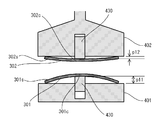
- FIG. 15 is a front sectional view showing a state in which the central portion of the bent substrate is abutted against the upper substrate.
- the bonding surface of the substrate 301 and the bonding surface of the substrate 302 are butted at the center.
- the stage 402 is moved to the lower stage 401 side along the Z direction in the Z direction elevating drive mechanism 406 of the stage drive mechanism 404.
- the substrate 301 held on the stage 401 in a state where the central portion 301 c is bent so as to be convex upward is abutted against the substrate 302 held on the upper stage 402.
- the bonding surface of the substrate 301 and the bonding surface of the substrate 302 are abutted at the center.
- the bonding surface between the substrate 301 and the bonding surface of the substrate 302 is terminated with a hydroxyl group (OH group) on the bonding surface by hydrophilization treatment ( M-OH) layer is interposed.
- FIG. 16 is a diagram for explaining a center push bonding method of pushing out the central portion of the substrate from above.
- FIG. 17 is a diagram illustrating the center push bonding method according to the present embodiment.
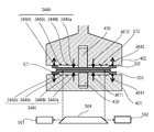
- 18A and 18B are diagrams illustrating a method of calibrating the parallelism and gap of the stage in units of microns. Specifically, a laser sensor (not shown) is provided for the stage and head described in FIG. Then, the size of three gaps (A, B, C) between the stage 401 and the stage 402 is measured with a laser, and the distance G1 is obtained to read the parallel deviation and the gap error. Based on the read result, the stage 402 is feedback-corrected by using the protruding mechanism 412 so that the parallelism and gap are set in advance. Actually, calibration can be performed every day in a necessary situation by pressing a calibration button (not shown) linked to these devices.
- FIG. 19 is a diagram for explaining a method of adjusting the gap by correcting the wafer thickness variation.
- the wafer thickness measuring means the wafer thickness of the substrates 301 and 302 is measured at three locations with a laser from above and below at the aligner position.
- the substrate bonding apparatus 100 moves so as to keep the specified gap between the stage 401 and the stage 402 before the new substrates 301 and 302 are inserted, three gaps between the stage 401 and the stage 402 (A , B, C) are measured to determine the distance G1.
- the distance G2 between the substrates 301 and 302 is automatically calculated from the wafer thicknesses t1 and t2 of the substrates 301 and 302 and the distance G1 between the stage 402 and the stage 401 measured in advance with the substrates 301 and 302 actually inserted and held. And feed back to the Z-axis. By doing so, a marginal alignment gap and zero point release can be achieved. Further, the laser measurement positions on the stages 401 and 402 may not be three points. One point is also acceptable. Further, it may not be performed every time the wafer is replaced, but may be performed in a timely manner or a specified number of times.
- a temporary bonding step for temporarily bonding the substrates 301 and 302 to each other is executed (step S104-2).
- the Z-direction lifting drive mechanism 406 is driven to lower the stage 402, and at least one substrate 301 is moved.
- 302 is applied with a pressure below a certain value or a pressure below a critical pressure.
- the application of pressure may be started simultaneously with the contact, or may be started after a certain time has elapsed after the contact. Moreover, the application of pressure may be performed over a part of time in the contact state, or may be performed over the whole.
- the application of pressure may be performed intermittently, and a constant pressure may be maintained during application, or may be changed with time.
- a constant pressure may be maintained during application, or may be changed with time.
- it can bond on the whole surface. If it is pushed in until it is completely pasted, pressure is applied and shifts, so it is not limited to the position where the entire surface is pressed.
- the critical pressure of the joint surface can be defined as a pressure at which a desired characteristic of the joint surface is changed or lost when the joint surface is pressed with a pressure exceeding that. For example, if too much pressure is applied to the bonding surface in the contact step (temporary bonding) before the step of finally forming the bonding interface (main bonding), the substrates 301 and 302 cannot be bonded and separated. Alternatively, it may be separated, and even if contact is made again and pressure is applied, desired bonding may not be possible.
- the substrates 301 and 302 that are in contact with each other can be separated while the substrates 301 and 302 remain in a non-bonded state without impairing surface characteristics for performing desired bonding. Can do.
- the lowest pressure at which the substrates 301 and 302 can be separated thereafter may be defined as the critical pressure.
- the separation can be made.
- characteristics such as desired bonding strength cannot be obtained even if a joining step is performed thereafter.
- the substrates 301 and 302 may be separated with a relatively small force.
- surface properties deteriorate due to destruction of the strongly formed bonding interface due to the separation, and as a result, desired bonding characteristics cannot be finally obtained.
- the critical pressure may be defined as a pressure at which a desired bonding cannot be performed when a pressure higher than that is applied, and a pressure at which a desired bonding cannot be performed when a pressure exceeding the critical pressure is applied. Also good.
- the critical pressure can be determined according to various factors such as the material forming the joint surface, the presence or absence of a surface layer on the joint surface, the characteristics of the surface layer, and the surface energy. Therefore, the bonding method of the present application may include a step (not shown) of determining the critical pressure of the bonding surface of at least one of the substrates 301 and 302 before the temporary bonding step (step S104-2). .
- the pressure applied in the temporary bonding step (step S104-2) is preferably equal to or lower than the critical pressure of the smaller critical pressure defined on both bonding surfaces of the substrates 301 and 302. Thereby, it is possible to ensure that an appropriate pressure is applied to any joint surface of the substrates 301 and 302. In the case where the critical pressure is not defined on one joint surface, a pressure that is equal to or lower than the critical pressure of the other joint surface on which the critical pressure is defined may be applied.
- a relative position measurement step (position shift amount measurement step) is executed (step S104-3).
- the position measuring means 500 uses the images (image data) GA relating to the transmitted light and reflected light of the illumination light emitted from the respective coaxial illumination systems of the cameras 501 and 502 to be attached to both the substrates 301 and 302. Further, the positions of the respective marks (MK1a, MK2a) and (MK1b, MK2b) are recognized.
- the controller 700 determines the amount of positional deviation ( ⁇ xa, ⁇ ya) ( ⁇ xb) between the marks (MK1a, MK2a), (MK1b, MK2b). , ⁇ yb).
- the relative position of the bonding surfaces of the substrates 301 and 302 is measured in a state under contact pressure
- the relative position of the bonding surfaces is the final bonding state in a state where contact and pressure are applied. Get closer to. For this reason, a more accurate and uniform contact state can be formed or maintained by pressurization.
- step S104-4 a determination step for determining whether or not the relative positional deviation amount is within the allowable error range is executed (step S104-4). Whether or not the positional deviation amount is within a predetermined allowable error range satisfies the condition that all the three positional deviation amounts ( ⁇ x, ⁇ y, ⁇ ) are within the respective allowable error ranges. It may be determined based on whether or not.
- a corrected movement amount calculation step is executed (step S104-5).
- the correction movement amounts of the substrates 301 and 302 are determined.
- the correction movement amounts of the substrates 301 and 302 for moving from the relative position measured in the relative position measurement step (step S104-3) to the desired relative position are obtained.
- the controller 700 selects desired values of both substrates 301 and 302 based on the positional deviation amounts ( ⁇ xa, ⁇ ya) and ( ⁇ xb, ⁇ yb) of the two sets of marks (MK1a, MK2a) and (MK1b, MK2b).
- a relative deviation amount ⁇ D (specifically ⁇ x, ⁇ y, ⁇ ) in the X direction, Y direction, and ⁇ direction from the position is calculated.
- the controller 700 finally adjusts the substrates 301 and 302 to the correction amounts ⁇ D ( ⁇ x, ⁇ y, and ⁇ ) corresponding to the relative deviation amounts ⁇ D ( ⁇ x, ⁇ y, ⁇ ) between the substrates 301 and 302.
- the movement path may be formed so that the bonding surfaces are brought into contact again with the relative movement of 302. That is, in the following relative position measurement step (step S104-3), the bonded surfaces that have been in contact with each other or the substrates 301 and 302 that have been in contact with each other are separated and contacted again after the movement of the correction movement amount. Further, from the relative position measured in the relative position measurement step, the pressure in the contact state of the joint surface is once removed or reduced, and the substrates 301 and 302 remain in contact with each other at the center.
- the movement path may be formed by relatively moving the substrates 301 and 302 in a direction substantially parallel to the bonding surface and pressurizing again. The formation of the above movement path is an example, and the present invention is not limited to this.
- the corrected movement amount may be determined as a function of a predetermined parameter.
- the measured relative positions of the substrates 301 and 302 are preferably one parameter that is taken into account by the function.
- the parameters of the function may include parameters other than the relative positions of the measured substrates 301 and 302.
- the movement paths of the substrates 301 and 302 for correcting the relative position can take various shapes, and therefore, the habits and errors of the movement mechanism or measurement mechanism of the substrates 301 and 302 at that time are considered as parameters. May be.
- a release process is performed in which the substrates 301 and 302 temporarily bonded to each other are released from each other (step S104-6).
- this release step the distance between the outer peripheral portion 301 s of the substrate 301 and the outer peripheral portion 302 s of the substrate 302 is increased in a state where the central portions of the substrates are abutted so as to maintain a certain distance. Return the deflection.
- a position correction process for correcting the relative positions of the substrates 301 and 302 is executed (step S104-7).
- the substrates 301 and 302 are moved by the correction movement amount determined in the correction movement amount calculation step (step S104-5).
- the substrates 301 and 302 are moved according to the obtained movement route. Thereby, the measured misalignment is corrected or minimized.
- the controller 700 instructs the drive mechanisms 403 to 407 of the stages 401 and 402 to move both the substrates 301 and 302 according to the correction path calculated in the correction movement amount calculation step (step S104-5). Put out.
- the stage driving mechanisms 403 and 404 drive the stage 402 in two translational directions (X direction and Y direction) and a rotational direction ( ⁇ direction) in accordance with an instruction from the controller 700, whereby both substrates 301 and 302 are driven. Are relatively moved, and the positional deviation amount ⁇ D is corrected.
- the movement of the substrates 301 and 302 includes a movement path in a state in which the substrates 301 and 302 are separated from each other, the joint surfaces are brought into contact with each other at the center and brought into contact again.
- the substrates 301 and 302 move while maintaining the contact state without separating the substrates 301 and 302 or the bonding surfaces, the substrates 301 and 302 are brought into contact with each other at the center when the movement is completed. A contact state is realized.
- step S104-7 the process returns to the step of bending the substrate 301 (step S103). Then, the position correction process (step S104-7) is repeated from the matching process (step S104) of the substrates 301 and 302 until the measured displacement amount of the substrates 301 and 302 falls within the allowable error range. Accordingly, it is possible to perform positioning between the substrates 301 and 302 with high accuracy and finally form a bonding interface or a bonding interface having high positioning accuracy between the substrates 301 and 302.
- step S104-4 a bonding step of bonding the substrates 301 and 302 to each other is executed (step S105).
- the bonding step first, the projecting mechanism 430 is immersed in the stage 402 as indicated by an arrow AR21 in FIG. Note that “depress the protrusion mechanism 430 into the stage 402” means that the pressing member 434 of the protrusion mechanism 430 is inserted into the stage 402 in detail.
- the substrates 301 and 302 maintain a state in which the central portions thereof are in contact with each other with a pressure that maintains a non-bonded state.
- the upper stage 402 is moved in a direction approaching the lower stage 401 by the Z-direction lifting drive mechanism 406.
- the substrate 302 is pressed against the substrate 301, the distance between the outer peripheral portion of the substrate 301 and the outer peripheral portion of the substrate 302 is reduced, and the substrates 301 and 302 are bonded to each other over the entire surface.
- the distance between the central portion of the substrate 301 and the central portion of the substrate 302 may be maintained by immersing the protruding mechanism 430 into the stage 402. Even in this case, by moving the upper stage 402 toward the lower stage 401, the distance between the outer peripheral portion of the substrate 301 and the outer peripheral portion of the substrate 302 is reduced, and the substrates 301 and 302 are overlapped with each other. Become.
- the so-called center push method in which the substrates 301 and 302 are bent by both the stages 401 and 402 is adopted.
- the bonding step as shown by arrows AR23 and AR24 in FIG.
- the substrates 301 and 302 maintain a state in which the central portions thereof are in contact with each other with a pressure that maintains a non-bonded state.
- the upper stage 402 is moved in a direction to approach the lower stage 401 by the Z-direction lifting drive mechanism 406.
- the substrate 302 is pressed against the substrate 301, the distance between the outer peripheral portion of the substrate 301 and the outer peripheral portion of the substrate 302 is reduced, and the substrates 301 and 302 are brought into contact with each other over the entire surface.
- a holding means such as a vacuum chuck for holding the substrate 302 is released, and then the vacuum suction of the lower stage 401 is operated and the lower side is operated. If the center portion of the substrate 301 is bent, the bending is also restored. Thereafter, it is preferable that the upper stage 402 is raised by the Z-direction lift drive mechanism 406.
- step S106 the bonding process of the substrates 301 and 302 is performed (step S106).
- bonding is performed after the bonding surface of the substrate 301 and the bonding surface of the substrate 302 are abutted on the entire surface.
- pressure may be applied to the bonding surfaces in which the bonding surfaces of the substrates 301 and 302 are in contact with each other.
- the pressure applied in a state where the bonding surfaces of the substrates 301 and 302 are abutted on the entire surface is preferably a pressure equal to or higher than the critical pressure or a pressure exceeding the critical pressure.
- the pressurization in a state where the bonding surfaces of the substrates 301 and 302 are abutted on the entire surface is mechanically applied to the substrates 301 and 302 by using a mechanism such as the Z-direction lifting drive mechanism 406 of the substrate bonding apparatus 100, for example. Can be added.
- the pressurization in a state where the bonding surfaces of the substrates 301 and 302 are in contact with each other gives an opposite charge to the substrates 301 and 302. You may add with respect to the board
- the pressurization mode, method, pressure, and the like in a state where the bonding surfaces of the substrates 301 and 302 are abutted on the entire surface are not limited to the above examples, and are appropriately adjusted according to various specific substrate bonding methods. May be.
- the bonding step may include a step of applying heat to the bonding surface in which the bonding surfaces of the substrates 301 and 302 are abutted on the entire surface.
- a bonding interface having desired characteristics can be formed.
- You may form the joining interface which finally has a desired characteristic by heating.
- the unnecessary surface layer existing on the surface of the bonding surface is finally diffused and removed, forming a bonding interface where the new surface directly contacts. It is possible to reduce the microscopic surface irregularities and increase the area of the substantial bonding interface. Thereby, various characteristics such as mechanical characteristics, electrical characteristics, and chemical characteristics of the bonding interface can be improved. Heating can be performed simultaneously with the above pressurization.
- heating and pressurization so that heating time and pressurization time may overlap a part or all.
- the electrostatic attraction due to this charge is used to electrically
- the substrates 301 and 302 may be heated while being pressed. Thereby, what is called anodic bonding can be performed.
- Heating may be performed by conducting heat from the stages 401 and 402 that support the substrates 301 and 302, or by conducting heat from the gas by heating the gas in the atmosphere of the substrates 301 and 302. It may be performed by irradiating the joint surface with light or the like.
- the final bonding interface between the substrates 301 and 302 may be formed by heating the bonding surfaces of the substrates 301 and 302 together with pressure. In this way, both substrates 301 and 302 are well aligned and final bonding is achieved.
- a step of performing a hydrophilization treatment for attaching water or an OH-containing substance to the surfaces of the bonding surfaces of the substrate 301 and the substrate 302 The substrate 302 is disposed with the bonding surfaces facing each other, the substrate 301 is bent with respect to the outer peripheral portion 301 s of the bonding surface so that the central portion 301 c protrudes toward the substrate 302, and the bonding of the substrate 301 is performed.
- the outer peripheral portion 301 s of the substrate 301 and the outer peripheral portion 302 s of the substrate 302 are in a state in which the surface and the joint surface of the substrate 302 are abutted with each other at a central portion, and in a state where the central portions are abutted with each other with a pressure that maintains a non-bonded state. , And the bonding surface of the substrate 301 and the bonding surface of the substrate 302 are abutted and bonded to each other. Thereby, it is possible to prevent the generation of voids between the substrates 301 and 302 and to perform bonding with high positional accuracy.
- the atmosphere around the substrate 302 and the substrate 301 may be evacuated before the substrates 301 and 302 are bonded to each other.
- the process of aligning the substrate 301 and the substrate 302 is performed in the atmosphere.
- the bonding surface of the substrate 301 and the bonding surface of the substrate 302 are brought into contact with each other at the center, a state in which water molecules are interposed between the bonding surface of the substrate 301 and the bonding surface of the substrate 302 is maintained. .
- the OH groups are not bonded to each other, and the substrates 301 and 302 can be peeled off without affecting the bonding surfaces.
- the step of abutting the bonding surface of the substrate 301 and the bonding surface of the substrate 302 at the center portion is performed in a vacuum, water molecules do not remain sufficiently on the bonding surface. When peeled off, the joint surface will be affected.
- the bonding surface of the substrate 301 and the bonding surface of the substrate 302 are not bonded, and the alignment between the substrate 301 and the substrate 302 can be repeatedly performed.
- the surrounding atmosphere is evacuated, so that the intermediate surface is interposed between the bonding surface of the substrate 302 and the bonding surface of the substrate 301. It is possible to prevent air from being mixed into the water. Therefore, voids can be prevented from occurring at the joint between the substrate 302 and the substrate 301. As a result, it is possible to bond the substrates 301 and 302 with high quality while aligning the substrates 301 and 302 with high accuracy.
- the positional deviation amount between the substrate 302 and the substrate 301 is set in a state where the bonding surface of the substrate 302 and the bonding surface of the substrate 301 are abutted at the center. If the measured positional deviation amount exceeds the allowable error range, the relative position between the substrate 301 and the substrate 302 is adjusted so that the positional deviation amount between the substrate 302 and the substrate 301 is reduced, and the position The measurement of the positional deviation amount between the substrate 301 and the substrate 302 and the adjustment of the relative position between the substrate 301 and the substrate 302 were repeated until the deviation amount was within the allowable error range. In this manner, the substrate 301 and the substrate 302 can be aligned with high accuracy by repeating until the positional deviation amount between the substrate 301 and the substrate 302 is within the allowable error range.
- the step of measuring the amount of positional deviation between the substrate 301 and the substrate 302 is performed in a state in which the bonding surface of the substrate 301 and the bonding surface of the substrate 302 are brought into contact with each other at a pressure or time that maintains the non-bonded state between the central portions. I made it.
- the substrate 301 and the substrate 302 are brought into contact with each other with an excessive pressure or left for a long time, water interposed between the bonding surface of the substrate 301 and the bonding surface of the substrate 302 is expelled, and the substrate 301 and the substrate 302 are discharged. May be joined.
- the pressure at which the substrate 301 and the substrate 302 are maintained in a non-bonded state in other words, maintaining a state in which water is interposed between the bonded surface of the substrate 301 and the bonded surface of the substrate 302,
- the alignment between the substrate 301 and the substrate 302 can be performed smoothly.
- the substrate 301 is formed into a flat plate shape so as to abut against the bonding surface of the substrate 302.
- the bonding surface of the substrate 301 and the bonding surface of the substrate 302 can be easily butted together and bonded together.
- the substrates 301 and 302 can be reliably bonded by pressurizing and bonding the substrate 301 and the substrate 302. .
- the step of abutting the first substrate and the second substrate is performed in a state in which the first substrate and the second substrate are abutted at a pressure that maintains a non-bonded state.
- the distance between the outer peripheral portion of the second substrate and the outer peripheral portion of the second substrate is reduced, and the bonding surface of the first substrate and the bonding surface of the second substrate are butted together and bonded.
- the alignment adjustment can be performed again by not increasing the pressure at which the substrates 301 and 302 are bonded to each other.
- the substrate bonding method in which the substrate warpage amount measuring step for measuring the warpage amount of the substrates 301 and 302 held on the stages 401 and 402 is performed immediately before the alignment step (see step S102 in FIG. 14).
- the center portions of the substrates 301 and 302 held on the stages 401 and 402 may be warped in a protruding manner.
- the distance between the central portions of the substrates 301 and 302 is shorter than the distance G2 obtained by subtracting the thickness of the substrates 301 and 302 from the distance G1 between the stages 401 and 402.
- the central portions of the substrates 301 and 302 are warped so as to protrude.
- the distance between the central portions of the stages 401 and 402 becomes shorter than the desired distance. Therefore, for example, when the total amount of warpage of the central portions of the substrates 301 and 302 is 10 ⁇ m or more, the substrates 301 and 302 come into contact with each other when the stages 401 and 402 are brought closer to each other so that the distance G2 becomes 10 ⁇ m. The process cannot be performed.
- the substrate bonding apparatus includes a displacement sensor 435 that detects the position of the protruding mechanism 430 (the position of the pressing member 434 of the protruding mechanism 430), similarly to the substrate bonding apparatus 100 according to the embodiment.
- the displacement sensor 435 projects the protrusion mechanism 430 on a flat reference substrate (not shown) without warpage.
- the position detecting step is detected at the position of the protrusion mechanism 430 in a state where the protrusion mechanism 430 is in contact with the substrate 301 and 302 at a very small pressure. A certain protruding mechanism position is detected (position detecting step).
- the position of the protrusion mechanism 430 in a state where the contact is made with a pressure having no magnitude is detected.
- substrate joining apparatus calculates the curvature amount p1, p2 from the stage 401,402 of the board
- the warpage amounts p1 and p2 of the substrates 301 and 302 from the stages 401 and 402 are calculated from the difference between the first protrusion mechanism position and the second protrusion mechanism position. Then, the stage 402 is brought closer to the stage 401 so that a distance G3 obtained by subtracting the warpage amounts p1 and p2 from the distance G2 becomes a desired distance.
- the alignment operation of the substrates 301 and 302 may be performed in a state where the stage 402 is brought close to the stage 401 so that the distance G3 becomes a desired distance.
- an insulating film such as an oxide film or a nitride film is formed on the bonding surface side of the substrates 301 and 302.
- an insulating film is formed only on the bonding surface side (only one side) of the substrates 301 and 302, the substrates 301 and 302 warp so as to protrude toward the bonding surface on which the insulating film is formed.
- an insulating film formed on the bonding surface side of both the substrates 301 and 302 is formed by a CVD (Chemical Vapor Deposition) method.
- the substrates 301 and 302 warp so as to be convex on one side which is a bonding surface thereof.
- CMP Chemical Mechanical Polishing
- the method for calculating the warpage amount is not limited to this method, and the other substrates 301 and 302 are calculated.
- a method of calculating the amount of warpage may be employed. For example, in the step of measuring the thickness of the substrates 301 and 302, the amount of warpage of the substrates 301 and 302 may be measured using a laser distance meter.
- the substrates 301 and 302 may be bent as shown in FIG.
- the larger one of the warpage amount (first warpage amount) of the substrate 301 and the warpage amount (second warpage amount) of the substrate 302 is specified.
- 302 may be bent so that the warpage amounts of the respective warpages are equal to or more than the specified warpage amount.
- the amount of warping of the substrate 301 is the amount of warping of the central portion 301 c of the substrate 301 toward the substrate 302
- the amount of warping of the substrate 302 is the amount of warping of the central portion 302 c of the substrate 302 toward the substrate 301.
- the substrate bonding apparatus when the warp amount p11 of the substrate 301 is larger than the warp amount p12 of the substrate 302, the substrate bonding apparatus according to this modification first has a large warp amount in the step of bending the substrate.
- the warp amount p11 of the substrate 301 is specified.
- the substrate bonding apparatus determines the position of the protruding mechanism 430 in a state where the protruding mechanism 430 is brought into contact with the substrates 301 and 302 with such a pressure that the substrates 301 and 302 do not bend.
- the warpage amounts p11 and p12 of the substrates 301 and 302 from the stages 401 and 402 are calculated.
- the substrate bonding apparatus bends the central portion 302c of the substrate 302 so that the warpage amount of the substrate 302 becomes equal to the specified warpage amount of the substrate 301 (see arrow AR61 in FIG. 23B). Thereafter, the substrate bonding apparatus executes a process of abutting the substrates 301 and 302 (step S104 in FIG. 14).
- the temporary bonding step and the bonding step are performed. Therefore, the two substrates 301 and 302 bonded to each other are performed. The amount of warpage can be reduced.
- the protrusion mechanism (first protrusion) that contacts the substrate 301 so that the warpage amount of the central portion of the substrate 301 is equal to the warpage amount of the central portion of the substrate 302.
- the protruding mechanism position of the protruding mechanism (second protruding mechanism) 430 to be brought into contact with 430 or the substrate 302 may be controlled.
- the substrate bonding apparatus causes the substrate 301 and the substrate 302 to approach each other (see arrows AR71 and AR72 in FIGS. 24A and 24B).
- the protrusion mechanism position of the protrusion mechanism 430 brought into contact with the central portion 302c of the substrate 302 is controlled so that the warp amount p13 (p15) of 301 is equal to the warp amount p14 (p16) of the substrate 302.
- the substrate bonding apparatus controls the protrusion mechanism 430 that is in contact with the substrate 301 so that the pressure by which the substrate 301 is pressed by the protrusion mechanism 430 is constant at a preset pressure. That is, when the substrate bonding apparatus lowers the stage 402 in the direction approaching the stage 401, the position of one of the two protruding mechanisms 430 is controlled, and the pressure of the other protruding mechanism 430 is controlled.
- the protruding mechanism 430 includes a voice coil motor 433, a pressing member 434, and a displacement sensor 435 as shown in FIG. In this case, the protrusion mechanism 430 controls the position of the pressing member 434 based on the detection value detected by the displacement sensor 435.
- the protrusion mechanism position of the protrusion mechanism 430 that is brought into contact with each other may be controlled.
- the bonding process is performed in a state where the warpage amounts of the substrates 301 and 302 are always equal, so that the warpage amounts of the two substrates 301 and 302 bonded to each other can be reduced.
- the relative positional relationship between the two substrates 301 and 302 temporarily bonded to each other is measured in the relative position measurement step (step S104-3), and the position correction step (step S104-7). ), The example in which the substrates 301 and 302 are moved by the correction movement amount determined in the correction movement amount calculation step (step S104-5) has been described.
- the relative position measurement step the amount of positional deviation in the rotational direction around the other XY direction or Z axis with respect to one of the two substrates 301 and 302 is measured.
- the XY direction corresponds to a direction orthogonal to the Z direction in which the stages 401 and 402 face each other as described above.
- the type of the amount of displacement measured in the relative position measurement process is not limited to these.
- a positional deviation amount corresponding to the warpage amount with respect to the outer peripheral portion of the central portion of the substrates 301 and 302 temporarily bonded to each other may be measured. If the measured displacement amount exceeds the allowable error range, the substrate 301, so that the displacement amount corresponding to the warpage amount is reduced in the step of bending the substrate after the release step is executed.
- Each of 302 may be bent.
- the substrate bonding apparatus performs a distance and thickness measurement process and a hydrophilization process (steps S200 and S201).
- the processes in steps S200 and S201 are the same as the processes in steps S100 and S101 described in the embodiment.
- the substrate bonding apparatus executes a step of bending the substrate (step S202).
- the substrate bonding apparatus specifies the larger amount of warpage between the warpage amount of the substrate 301 and the warpage amount of the substrate 302, and the warpage amounts of the respective substrates 301 and 302 are determined as the specified warpage amount.
- substrates 301 and 302 is bent so that it may become above.
- the substrate bonding apparatus performs an alignment process, a substrate matching process, and a temporary bonding process (steps S203, S204, and S205).
- the processing in steps S203 to S205 is the same as the processing in steps S102, S104, and S104-2 described in the embodiment.
- the substrate bonding apparatus executes a relative position measurement process (step S206).
- the substrate bonding apparatus has a positional displacement amount in the rotational direction around the other XY direction or Z axis with respect to one of the two substrates 301 and 302, and the outer peripheral portion of the central portion of the substrates 301 and 302 that are temporarily bonded to each other.
- the positional deviation amount corresponding to the warpage amount is measured.
- the substrate bonding apparatus includes a distance LM1 between the centers of two alignment marks MK1a and MK1b provided on the substrate 301, and two alignment marks MK2a provided on the substrate 302. A distance LM2 between the centers of MK2b is calculated.
- the substrate bonding apparatus measures the amount of displacement according to the amount of warpage of the substrates 301 and 302 that are temporarily bonded to each other by calculating the difference between the calculated distances LM1 and LM2.
- the distance LM1 between the alignment marks MK1a and MK1b of the substrate 301 is longer than the distance LM2 between the alignment marks MK2a and MK2b of the substrate 302, they are temporarily joined together as shown in FIG.
- the substrates 301 and 302 are warped so as to be convex toward the substrate 302 side.
- the difference between the distance LM1 and the distance LM2 becomes longer as the warpage amount of the substrates 301 and 302 temporarily bonded to each other is larger.
- the substrate bonding apparatus responds to the relative positional deviation amount of the two substrates 301 and 302 in the XY direction or the rotation direction around the Z axis and the warpage amount of the temporarily bonded substrates 301 and 302. It is determined whether or not the relative positional deviation amount is within an allowable error range (step S207).
- the substrate bonding apparatus determines that the relative positional deviation amount is within the allowable error range (step S207: Yes)
- the substrate bonding apparatus executes a bonding process and a bonding process (steps S212 and S213).
- the processing in steps S212 and S213 is the same as the processing in steps S105 and S106 described in the embodiment.
- step S208 when the substrate bonding apparatus determines that the relative positional deviation amount exceeds the allowable error range (step S207: No), it executes a correction movement amount / warpage amount calculation step (step S208).
- a desired position is calculated from the relative position measured in the relative position measurement step (step S104-3) in the same manner as the correction movement amount calculation step (step S104-5) described in the embodiment.
- the correction movement amount of the substrates 301 and 302 for moving to the relative position is calculated.
- the substrate bonding apparatus determines the warpage amount of each of the substrates 301 and 302 in the substrate abutting step (step S204) for abutting the substrates 301 and 302 together.
- the substrate bonding apparatus includes a protrusion amount of the protrusion mechanism (first protrusion mechanism) 430 that presses the substrate 301 and a protrusion mechanism (second protrusion mechanism) that presses the substrate 302 in the substrate matching step.
- the protrusion amount of 430 is set.
- the substrates 301 and 302 are brought into contact with each other in a state where the warp amount p21 of the substrate 301 and the warp amount p22 of the substrate 302 are equal, and then temporarily joined.
- FIG. 27B it is assumed that the two substrates 301 and 302 temporarily bonded to each other are warped in a convex shape toward the substrate 302 side.
- the distance LM2 between the centers of the alignment marks MK1a and MK1b on the substrate 301 is shorter than the distance LM1 between the centers of the alignment marks MK2a and MK2b on the substrate 302. In this case, as shown in FIG.
- the substrate bonding apparatus protrudes to press the central portions 301c and 302c of the substrates 301 and 302 so that the warp amount p22 of the substrate 302 is longer than the warp amount p21 of the substrate 301.
- the protrusion amount of the mechanism 430 is set. For example, when the substrates 301 and 302 are abutted and temporarily bonded in a state where the warp amount p21 of the substrate 301 and the warp amount p22 of the substrate 302 are both set to 15 ⁇ m, the substrates 301 and 302 temporarily bonded to each other are shown in FIG. Suppose you warp as shown.
- the substrate bonding apparatus sets the protrusion amount of each protrusion mechanism 430 so that the warp amount p21 of the substrate 301 is 13 ⁇ m and the warp amount p22 of the substrate 302 is 17 ⁇ m, for example.
- FIG. 28A when the substrates 301 and 302 are brought into contact with each other in a state where the warping amounts p21 and p22 of the substrates 301 and 302 are equal to each other and temporarily joined, as shown in FIG. Suppose that it is warped in a convex shape.
- the distance LM2 between the centers of the alignment marks MK1a and MK1b on the substrate 301 is longer than the distance LM1 between the centers of the alignment marks MK2a and MK2b on the substrate 302. In this case, as shown in FIG.
- the substrate bonding apparatus projects the center portions 301c and 302c of the substrates 301 and 302 so that the warp amount p21 of the substrate 301 is longer than the warp amount p22 of the substrate 302.
- the protrusion amount of the mechanism 430 is set. For example, when the substrates 301 and 302 are abutted and temporarily bonded in a state where the warp amount p21 of the substrate 301 and the warp amount p22 of the substrate 302 are both set to 15 ⁇ m, the substrates 301 and 302 temporarily bonded to each other are shown in FIG. Suppose you warp as shown. In this case, the substrate bonding apparatus sets the protrusion amount of each protrusion mechanism 430 so that the warp amount p21 of the substrate 301 is 17 ⁇ m and the warp amount of the substrate 302 is 13 ⁇ m, for example.
- the substrate bonding apparatus determines the protrusion amount of the protrusion mechanism 430 that presses each of the substrates 301 and 302 according to the warpage amount of the central portions 301c and 302c of the substrates 301 and 302 that are temporarily bonded to each other with respect to the outer peripheral portions 301s and 302s. It is set based on the correlation between the amount of misalignment and the amount of protrusion of the protrusion mechanism 430 that presses each of the substrates 301 and 302.
- the substrate bonding apparatus calculates the correlation between the amount of displacement according to the amount of warpage of the substrates 301 and 302 temporarily bonded to each other and the amount of protrusion of the protrusion mechanism 430 that presses each of the substrates 301 and 302.
- the correlation data shown may be held in advance.
- the substrate bonding apparatus refers to the correlation data held in advance, and determines each of the substrates 301 and 302 from the amount of displacement according to the amount of warpage of the substrates 301 and 302 temporarily bonded to each other calculated in the relative position measurement step.
- the protrusion amount of the protrusion mechanism 430 to be pressed is set.
- the substrate bonding apparatus acquires correlation data by measuring the amounts of warpage of the substrates 301 and 302 that are temporarily bonded to each other while changing the protruding amount of the protruding mechanism 430 that presses the substrates 301 and 302 in advance. What should I do?
- the substrate bonding apparatus is a relational expression showing a correlation between the amount of displacement according to the amount of warpage of the substrates 301 and 302 temporarily bonded to each other and the amount of protrusion of the protrusion mechanism 430 that presses each of the substrates 301 and 302. May be stored in advance.
- the substrate bonding apparatus determines that the amount of displacement according to the amount of warpage of the central portions 301c and 302c of the substrates 301 and 302 temporarily bonded to the outer peripheral portions 301s and 302s exceeds the allowable error range, You may make it change the protrusion amount of the protrusion mechanism 430 which presses 301,302 only by the unit amount set beforehand.
- the substrate bonding apparatus performs a substrate releasing step and a position correcting step (steps S209 and S210).
- steps S209 and S210 are the same as the processes in steps S104-6 and S104-7 described in the embodiment.
- the substrate bonding apparatus executes a step of bending the substrates 301 and 302 based on the protrusion amount of the protrusion mechanism 430 that presses the substrates 301 and 302, respectively, set in the above-described correction movement amount / warpage amount calculation step. (Step S211). Then, the substrate bonding apparatus executes the process of step S204 again. Then, the step of bending the substrate, the substrate matching step, the relative position measurement step, the correction movement amount / warpage amount calculation step, the substrate release step and the position until the positional deviation amount of the substrates 301 and 302 falls within the allowable error range. The correction process is repeated.
- the bonding process is performed after the positional deviation amount corresponding to the warpage amount of the substrates 301 and 302 temporarily bonded to each other falls within the allowable error range.
- the amount of warpage 302 can be greatly reduced.
- the warpage amount of each substrate in the substrate matching step which is set at the time of bonding of one substrate among the bonding of the substrates repeatedly performed a plurality of times, You may make it set as the curvature amount of each board
- gas may be blown into the gap between the peripheral portion of the substrate 301 and the peripheral portion of the substrate 302 in the direction from the peripheral edge of the substrates 301 and 302 toward the central portion of the substrates 301 and 302. .
- the stages 401 and 402 according to this modification have a holding mechanism 3440 that holds the substrates 301 and 302 and a protrusion that bends the substrates 301 and 302 by pressing the central portion of the substrates 301 and 302. And a mechanism 430.
- the holding mechanism 3440 includes a vacuum chuck having a plurality (four in FIG. 29) of annular suction portions 3440a, 3440b, 3440c, and 3440d.
- the adsorption portions 3440a, 3440b, 3440c, and 3440d have different diameters and are arranged concentrically.
- the substrates 301 and 302 are held on the stages 401 and 402 while being sucked by the suction portions 3440a, 3440b, 3440c, and 3440d.
- the suction portions 3440a and 3440b are opposed to the central portions of the substrates 301 and 302
- the suction portions 3440c and 3440d are opposed to the peripheral portions of the substrates 301 and 302.
- the adsorption units 3440a, 3440b, 3440c, and 3440d can take a state of adsorbing the substrates 301 and 302 and a state of not adsorbing the substrates.
- the suction portions 3440a and 3440b disposed relatively inside the stages 401 and 402 are not vacuum-sucked, and the suction portions 3440c and 3440d disposed relatively outside the stages 401 and 402 are vacuum-sucked.
- the radius L1 of the suction part 3440a located closest to the center C1 of the stages 401, 402 the distance L2 between the suction part 3440a and the suction part 3440a adjacent to the outside on the outside, the suction part 3440b and the suction part.
- the fixed positions of the substrates 301 and 302 are determined by the distance L3 between the adsorbing portion 3440c adjacent to the outer side 3440b and the distance L4 between the adsorbing portion 3440c and the outermost adsorbing portion 3440d.
- the substrate 301 is bent such that the central portion 301c protrudes toward the substrate 302 with respect to the outer peripheral portion 301s of the joint surface.
- the two suction portions 3440c and 3440d on the peripheral side of the stage 401 suck the substrate 301, while the two suction portions 3440a and 3440b on the central side of the stage 401 stop sucking the substrate 301 (FIG. (See arrows AR41 and AR42 of 30A).
- the stages 401 and 402 hold the substrates 301 and 302 at two suction positions (holding positions) at different distances from the center of the substrates 301 and 302 in the peripheral portions of the substrates 301 and 302.
- the substrate 302 is bent such that the central portion 302c protrudes toward the substrate 301 with respect to the outer peripheral portion 302s of the bonding surface.
- the two suction portions 3440c and 3440d on the peripheral side of the stage 402 suck the substrate 302, while the two suction portions 3440a and 3440b on the center side of the stage 402 stop sucking the substrate 302 (FIG. (See arrows AR41 and AR42 of 30A).
- the stage 402 is raised and the gap between the substrates 301 and 302 is widened, and the protruding mechanism 430 of the stage 401 is immersed in the stage 401 (see FIG. 30B).
- 30B) see arrow AR51 in FIG. 30B
- the projection mechanism 430 of the stage 402 moves in the direction in which the stage 402 is immersed (see arrow AR52 in FIG. 30B).
- the rising speed of the stage 402 is controlled so that the tensile pressure of the substrate 302 when the substrate 302 is peeled off from the substrate 301 is constant.
- the suction portions 3440a and 440b on the center side of the stage 401 and the suction portions 3440a and 3440b on the center side of the stage 402 resume suction of the substrates 301 and 302 (see arrows AR61 and AR62 in FIG. 30B).
- the timing at which the suction units 3440a and 3440b resume the suction of the substrates 301 and 302 is such that the protrusion mechanism 430 of the stage 401 is immersed in the stage 401 while the gap between the substrates 301 and 302 is widened, and the protrusion mechanism of the stage 402 430 may be the timing before and after the timing of immersing the stage 402, or may be simultaneous.
- the blower 3811 blows gas in the gap between the peripheral portion of the substrate 301 and the peripheral portion of the substrate 302 in the direction from the peripheral edge of the substrates 301 and 302 toward the central portion of the substrates 301 and 302 (FIG. 30B). (See arrow AR6).
- a force in a direction in which the substrate 302 is peeled off from the substrate 301 is generated from the differential pressure between the pressure at which the gas is blown by the blower 3811 and the suction pressure at which the adsorption portions 3440a and 3440b adsorb.
- the substrate 302 is detached from the substrate 301, and the substrate 301 and the substrate 302 are released.
- the blower 3811 does not blow gas into the gap between the peripheral portion of the substrate 301 and the peripheral portion of the substrate 302, and the protrusion mechanism 430 is immersed in the stages 401 and 402, and the suction portion. You may make it perform only adsorption
- the holding positions of the substrates 301 and 302 by the stages 401 and 402 are changed stepwise toward the outside of the substrates 301 and 302, thereby reducing the distance between the outer peripheral portions of the substrates 301 and 302.
- the structure which bonds 301,302 together may be sufficient.
- the stages 401 and 402 according to this modification have a holding mechanism 3440 for holding the substrates 301 and 302 and a protrusion that bends the substrates 301 and 302 by pressing the central portion of the substrates 301 and 302. And a mechanism 430.
- the substrate 301 is formed such that the central portion 301c protrudes toward the substrate 302 with respect to the outer peripheral portion 301s of the bonding surface. It is bent. At this time, the two suction portions 3440 c and 3440 d on the peripheral side of the stage 401 suck the substrate 301, while the two suction portions 3440 a and 3440 b on the center side of the stage 401 stop sucking the substrate 301.
- the substrate 302 is bent such that the central portion 302c protrudes toward the substrate 301 with respect to the outer peripheral portion 302s of the bonding surface.
- the two suction portions 3440c and 3440d on the peripheral side of the stage 402 suck the substrate 302, while the two suction portions 3440a and 3440b on the center side of the stage 402 stop sucking the substrate 302 (FIG. (See arrows AR41 and AR42 of 30A).
- the suction portion 3440 c on the center side of the stages 401 and 402 is stopped. . That is, by stopping the adsorption of the substrates 301 and 302 in order from the adsorption portion having a short distance from the central portion of the substrates 301 and 302 at the peripheral portions of the substrates 301 and 302, the peripheral portion of the substrate 301 and the peripheral portion of the substrate 302 Contact. Thereby, the contact portion between the substrates 301 and 302 spreads from the central portion of the substrates 301 and 302 toward the peripheral side. Thereafter, as shown in FIG.
- the adsorbing portion 440d that adsorbs the substrates 301 and 302 stops, so that the entire bonding surfaces of the substrates 301 and 302 are in contact with each other.
- the bonding step (S106) is performed in a state where the entire bonding surfaces of the substrates 301 and 302 are in contact with each other.
- the substrate 301 is held on the stage 401 at four suction positions (holding positions) at different distances from the central portion of the substrate 301 in the peripheral portion of the substrate 301, and the center of the substrate 302 in the peripheral portion of the substrate 302
- the substrate 302 is held on the stage 402 at four suction positions having different distances from the part. Then, the suction and holding of the substrates 301 and 302 is stopped in order from the suction position where the distance from the center of the substrates 301 and 302 in the peripheral portion of the substrates 301 and 302 is short, so that the peripheral portion of the substrate 301 (302) (301) is brought into contact with the periphery.
- one substrate 301 (302) that has been bent comes into contact with the other substrate 302 (301) sequentially from the central portion toward the peripheral side of the substrates 301 and 302 in the process of restoring the original flat plate shape. Go.
- the air existing between the two substrates 301 and 302 is pushed out to the peripheral side of the substrates 301 and 302 in the process of restoring one substrate 301 (302) to a flat plate shape. Therefore, when the substrates 301 and 302 are bonded to each other, gas can be prevented from entering between the substrates 301 and 302. Further, by preventing gas from entering between the two substrates 301 and 302, generation of a so-called void between the two bonded substrates 301 and 302 is suppressed.
- the distance between the outer peripheral portion of the substrate 301 and the outer peripheral portion of the substrate 302 is reduced by sandwiching the substrates 301 and 302 between the stages 401 and 402, so that the substrates 301 and 302 are connected to each other. Is in a state of being abutted on the entire surface.
- the substrates 301 and 302 are deformed along the irregularities when the substrates 301 and 302 are sandwiched between the stages 401 and 402.
- the substrates 301 and 302 may be distorted.
- the substrates 301 and 302 are abutted on the entire surface in a state where the central portions of the substrates 301 and 302 are sandwiched by the protruding mechanisms 430 of the stages 401 and 402. It becomes a state. Therefore, at least in the region excluding the central portion of the substrates 301 and 302, the occurrence of distortion in the substrates 301 and 302 due to the presence of unevenness in the portion where the substrates 301 and 302 are sandwiched is suppressed.
- the holding mechanism 3440 is configured by a vacuum chuck.
- the present invention is not limited to this.
- the holding mechanism is configured by a mechanical chuck or an electrostatic chuck. May be.
- the holding mechanism may be configured by combining at least two types of chucks among a vacuum chuck, a mechanical chuck, and an electrostatic chuck.
- the holding mechanism 3440 has been described with respect to the example in which the holding unit 3440 is configured by the annular suction units 3440a, 3440b, 3440c, and 3440d.
- the structure of the suction unit is not limited thereto, A structure may be adopted in which the substrates 301 and 302 are sucked through holes opened at a plurality of locations on the upper surface of the lower stage 401 and the lower surface of the upper stage 402.
- the two suction portions 3440 c and 3440 d on the peripheral sides of the stages 401 and 402 are replaced with the substrates 301 and 302.
- the example in which the two suction portions 3440a and 3440b on the center side of the stages 401 and 402 are stopped sucking the substrates 301 and 302 is shown.
- the substrates 301 and 302 may be sucked by only one suction portion 3440d on the peripheral side of the stages 401 and 402.
- 33A and 33B components similar to those in the embodiment are denoted by the same reference numerals as in FIG. 1, and components similar to those of the above-described modification are denoted by the same symbols as in FIGS. ing.
- the temporary bonding between the substrates 301 and 302 may stop inside the substrate 301 or 302 from the position where the camera 501 or 502 images the alignment mark (see the broken arrow in FIG. 33A).
- the positional deviation amount between the substrates 301 and 302 in the bonding process may not be sufficiently reflected as the positional deviation of the alignment mark in the relative position measuring process.
- Air may be discharged (see arrows AR71 and AR72 in FIG. 33B).
- the stage 401 holds the outer peripheral portion of the substrate 301 and the stage 402 holds the outer peripheral portion of the substrate 302, and the center portion of the substrates 301 and 302 is temporarily bonded, so that the stage 401 is placed between the substrate 301 and the substrate 301.
- Air is discharged to each of the region (first region) S71 and the region (second region) S72 between the stage 402 and the substrate 302.
- the air pressure in the regions S71 and S72 is increased.
- the temporary bonding between the substrates 301 and 302 is advanced to the more peripheral side of the substrates 301 and 302.
- the substrates 301 and 302 are temporarily joined to the peripheral sides of the substrates 301 and 302 from the positions where the cameras 501 and 502 capture the alignment marks (see the broken arrows in FIG. 33B).
- the relative position measurement step it is preferable to image the alignment mark with the cameras 501 and 502 after the temporary bonding between the substrates 301 and 302 is advanced to the peripheral side of the substrates 301 and 302 as much as possible.
- the adsorption portions 3440a, 3440b, 3440c, and 3440d is stopped and the substrates 301 and 302 are brought into contact with each other over the entire surface, they are already temporarily joined to the vicinity of the outer peripheral portion. It is difficult for relative displacement of the substrates 301 and 302 to occur.
- the shortening of the distance between the stages 401 and 402 is restricted by the parallelism of the mounting surfaces of the stages 401 and 402. Further, if the substrates 301 and 302 are too close to each other, the substrate 302 may not be peeled from the substrate 301.
- the substrates 301 and 302 are expanded in a direction approaching each other. It is possible to widen the temporary joining portion between 301 and 302 to the peripheral side of the substrates 201 and 302. Accordingly, the region where the substrates 301 and 302 are temporarily bonded can be expanded without bringing the outer peripheral portions of the substrates 301 and 302 too close to each other, so that the substrate 302 is not affected by the undulation of the stage. It can prevent that it does not peel off.
- the positional deviation amount of the substrates 301 and 302 when the substrates 301 and 302 are attached to each other is reflected in the positional deviation amount of the alignment mark recognized by the cameras 501 and 502. Therefore, it is possible to correct the positional deviation amount by peeling again, and when the substrates 301 and 302 are bonded together on the entire surface in the subsequent bonding process, the substrates 301 and 302 are not displaced from each other without causing a positional shift. Can be pasted together. Therefore, the bonding accuracy between the substrates 301 and 302 is improved.
- the gap between the outer peripheral portions of the substrates 301 and 302 is maintained.
- the substrate 302 is peeled from the substrate 301, if the substrates 301 and 302 are sucked by all the suction portions 3440a, 3440b, 3440c, and 3440d of the stages 401 and 402, the space between the substrates 301 and 302 and the stages 401 and 402 is reduced. A large negative pressure is generated. Then, when the fixing strength of the stages 401 and 402 is small, the stage 401 may be lifted or the stage 402 may be pulled down, and the stage may be damaged.
- the stage 402 is lifted while air is discharged into the gap between the outer peripheral portions of the substrates 301 and 302, and finally the central portions of the substrates 301 and 302 are sucked by the suction portions 3440a and 3440b located at the central portions of the stages 401 and 402.
- a method of peeling the substrate 302 from the substrate 301 is preferable.
- the joining does not necessarily have to be joined to the outside of the mark recognition position. As shown in FIG. 30A, even if it is inside the mark position, if the bonding force is strong, the position shift can be detected. In some cases, the joining may be advanced to the vicinity without exceeding the mark position.
- the present invention is not limited to this.
- a configuration in which heating is performed only by applying pressure to the substrates 301 and 302 in a state where the entire bonding surfaces of the substrates 301 and 302 are in contact with each other may be employed.
- the substrates 301 and 302 may be heated in an annealing furnace (not shown) separate from the substrate bonding apparatus after being taken out from the substrate bonding apparatus 100.
- the substrate bonding apparatus may be configured such that only the substrates 301 and 302 are heated and no pressure is applied in a state where the entire bonding surfaces of the substrates 301 and 302 are in contact with each other.
- the lower stage 401 may be made of a transparent material, or the material constituting the lower stage 401 may be transparent. Thereby, light (including the transmitted light and the reflected light) emitted from the light source for position measurement can pass through the transparent material of the lower stage 401. Therefore, there is no restriction on the design of the substrate support means.
- the substrate heating unit 420 is made of a transparent material, or the material constituting the substrate heating unit 420 is transparent, and the heater 421 in the substrate heating unit 420 is disposed between the heater wires.
- a predetermined interval may be provided.
- the transparent material a glass material or a ceramic material is preferably used. Even if it does not look transparent when viewed with the naked eye, the lower stage 401 may be made of a material that transmits light emitted from the light source.
- At least a part of the lower stage 401 is made of a transparent material, or a material constituting the lower stage 401 is transparent, and at least a part of the substrate heating means 420 is made of a transparent material, Or the material which comprises the board
- the present invention is not limited to this, and two alignment marks are moved by moving one camera. You may make it image
- the stage 401 is moved in the X direction, but the present invention is not limited to this.
- the stage 401 may be fixed.
- the stage 402 is moved in the X direction, the Y direction, the Z direction, and the ⁇ direction, so that the stages 401 and 402 are relatively moved in these directions. It is not limited to this. For example, conversely, when the stage 402 is fixed and the stage 401 is moved in the X direction, the Y direction, the Z direction, and the ⁇ direction, the stages 401 and 402 are relatively moved in these directions. It may be.
- the substrate 301 or 302 having a predetermined shape or material has been described.
- the present invention is not limited to this.
- the substrates 301 and 302 are formed of a glass substrate, an oxide substrate, or a nitride substrate.
- the present invention is not limited thereto, and the substrates 301 and 302 may be Si substrates.
- One of the substrates 301 and 302 may be a Si substrate and the other may be a glass substrate.
- the substrates 301 and 302 may be a substrate on which an oxide film is formed, a substrate on which a nitride film is formed, a carbide substrate, or a ceramic substrate.
- the oxide film and the nitride film may be formed by a CVD (Chemical Vapor Deposition) method.
- CVD Chemical Vapor Deposition
- the substrates 301 and 302 may be warped in a convex shape toward the surface on which the oxide film or nitride film is formed.
- the present invention is not limited to this.
- the surface activation process may be performed outside the substrate bonding apparatus 100.
- the surface activation treatment can be performed only by opening the chamber 200 and exposing the inside of the chamber 200 to the atmosphere.
- the configuration described in the above embodiment can be selected or changed to another configuration as appropriate.
- the present invention is suitable for manufacturing, for example, a CMOS image sensor, a memory, an arithmetic element, and a MEMS.
Abstract
A substrate bonding method comprises: a hydrophilization process step of performing a hydrophilization process for causing water or an OH-containing substance to become attached to a bonding face surface of each of substrates (301, 302); a substrate warping step of warping the substrate (301); an abutting step of abutting the bonding face of the substrate (301) and the bonding face of the substrate (302) against each other at center portions thereof; and a laminating step of reducing the distance between an outer peripheral portion of the substrate (301) and an outer peripheral portion of the substrate (302) with the center portions thereof abutted against each other so as to maintain a constant distance, and reducing the distance until the bonding face of the substrate (301) and the bonding face of the substrate (302) are positioned for lamination across the entire faces thereof. Before or after the abutting step, the distance between the substrates (301, 302) is measured and the distance between the outer peripheral portions of the substrates (301, 302) is reduced.
Description
本発明は、基板接合方法に関する。
The present invention relates to a substrate bonding method.
エレクトロニクスの分野において、電子部品などと基板との接合、電子回路や電子配線が設けられた基板同士の接合のための実装技術が開発されている。このような実装技術により接合される被接合物は、その接合面に、電子回路などに電気的に接続された電極を有している。この電極同士が接合されることで、被接合物間の電気的接続が確立される。
In the field of electronics, mounting technology has been developed for bonding electronic components and substrates to each other, and bonding between substrates provided with electronic circuits and electronic wiring. An object to be bonded by such a mounting technique has an electrode electrically connected to an electronic circuit or the like on the bonding surface. The electrodes are joined together to establish electrical connection between the objects to be joined.
電子機器は、常に小型化及び軽量化が要求されている。これにともない、電子回路などの回路パターンの高密度化及び微細化が進んでいる。これにより、互いに接合される被接合物同士の位置決め精度を向上する要求が高まってきている。
Electronic devices are always required to be smaller and lighter. Accordingly, circuit patterns such as electronic circuits have been increased in density and miniaturization. Thereby, the request | requirement which improves the positioning accuracy of the to-be-joined objects joined mutually has increased.
この要求に応えるために、被接合物同士を接触させた後、両被接合物の位置ずれを測定し、位置ずれを補正して前記両被接合物の位置合わせを行った後、被接合物同士を接合する接合方法が開示されている(例えば特許文献1参照)。
In order to meet this requirement, after the objects to be joined are brought into contact with each other, the positional deviation of both the objects to be joined is measured, the positional deviation is corrected, and the positions of both the objects to be joined are adjusted. A joining method for joining together is disclosed (for example, see Patent Document 1).
ところで、被接合物として平板状の基板同士を接合する場合、ウエハは、チップなどに比較すると接合面の面積が大きい。このため、平板状の基板同士の平坦な接合面同士を突き合わせて接合すると、接合面の間に空気が入り込み、ボイドが生じて製品不良となってしまうことがある。
By the way, when flat substrates are bonded as objects to be bonded, the wafer has a larger bonding surface area than a chip or the like. For this reason, when flat joining surfaces of flat substrates are brought into contact with each other and joined, air may enter between the joining surfaces, resulting in voids and product defects.
そこで、基板同士の位置合わせを行った後、ウエハの中央部を、接合対象となる相手側ウエハに向けて押圧して撓ませて接合を行う手法が用いられている。この手法では、ウエハの外周部を保持した状態で中央部を押圧して、ウエハの接合面を、中央部が相手側ウエハに向けて凸となるよう撓ませることによって、相手側ウエハに突き当てる。すると、撓ませたウエハは、凸となった中央部が相手側ウエハの接合面に突き当たる。その後、撓ませたウエハを解放する。すると、撓んでいたウエハは、元の平板状に復元し、相手側ウエハと接合面の全面で接合される。
Therefore, a technique is used in which, after aligning the substrates, the center of the wafer is pressed and bent toward the mating wafer to be bonded. In this method, the central portion is pressed while holding the outer peripheral portion of the wafer, and the bonding surface of the wafer is bent against the counterpart wafer by bending the central portion so that the central portion is convex toward the counterpart wafer. . Then, the bent central portion of the bent wafer hits the bonding surface of the mating wafer. Thereafter, the bent wafer is released. Then, the bent wafer is restored to the original flat plate shape, and bonded to the mating wafer and the entire bonding surface.
このとき、撓んでいたウエハは、元の平板状に復元する過程で、凸となった中央部から外周側に向けて順次相手側ウエハに接触していくので、ウエハ同士の間の空気が外周側に押し出され、これによってウエハ同士の接合面の間に空気が入るのを防止している。
At this time, in the process of restoring the original flat plate shape, the bent wafer sequentially contacts the counterpart wafer from the convex central part toward the outer peripheral side, so the air between the wafers This prevents the air from entering between the bonding surfaces of the wafers.
しかしながら、上記したようにウエハ同士の位置合わせを行った後、ウエハの中央部を、接合対象となる相手側ウエハに向けて押圧して撓ませる間や、撓ませたウエハを解放してウエハが元の平板状に復元する間に、ウエハの位置ずれが生じてしまうことがある。
However, after the wafers are aligned as described above, the center portion of the wafer is pressed against the mating wafer to be bonded and bent, or the bent wafer is released and the wafer is released. While restoring the original flat shape, the wafer may be displaced.
本発明は上記事由に鑑みてなされたものであり、基板同士を接合する際に、基板同士の間でのボイドの発生を防ぐとともに、高い位置精度で接合することのできる基板接合方法を提供することである。
The present invention has been made in view of the above reasons, and provides a substrate bonding method capable of preventing generation of voids between substrates and bonding with high positional accuracy when bonding substrates. That is.
上記目的を達成するために、本発明に係る基板接合方法は、
第一の基板と第二の基板とを接合する方法であって、
前記第一の基板及び前記第二の基板のそれぞれの接合面の表面に水又はOH含有物質を付着させる親水化処理を行う親水化処理工程と、
前記第一の基板を前記接合面の外周部に対して中央部が前記第二の基板側に突出するように撓ませる基板を撓ませる工程と、
前記第一の基板の前記接合面と前記第二の基板の前記接合面とを、前記中央部同士で突き合わせる突き合わせ工程と、
前記中央部同士が一定の距離を保つように突き合わせた状態で、前記第一の基板の外周部と前記第二の基板の外周部との距離を縮めて前記第一の基板の前記接合面と前記第二の基板の前記接合面とを全面で張り合わせる張り合わせ工程と、を含み、
前記突き合わせ工程前または前記突き合わせ工程後において、前記第一の基板と前記第二の基板との間の距離を測定して、前記第一の基板の外周部と前記第二の基板の外周部との距離を縮める。 In order to achieve the above object, a substrate bonding method according to the present invention includes:
A method of bonding a first substrate and a second substrate,
A hydrophilization treatment step of performing a hydrophilization treatment for attaching water or an OH-containing substance to the surfaces of the respective bonding surfaces of the first substrate and the second substrate;
Bending the substrate for bending the first substrate with respect to the outer peripheral portion of the bonding surface such that a central portion protrudes toward the second substrate;
A butting step of abutting the joint surface of the first substrate and the joint surface of the second substrate at the central portions;
In a state where the central portions are in contact with each other so as to maintain a constant distance, the distance between the outer peripheral portion of the first substrate and the outer peripheral portion of the second substrate is reduced, and the bonding surface of the first substrate A pasting step of laminating the joint surface of the second substrate over the entire surface,
Before or after the matching step, the distance between the first substrate and the second substrate is measured, and the outer peripheral portion of the first substrate and the outer peripheral portion of the second substrate Reduce the distance.
他の観点から見た本発明に係る基板接合方法は、
第一の基板と第二の基板とを接合する方法であって、
前記第一の基板及び前記第二の基板のそれぞれの接合面の表面に水又はOH含有物質を付着させる親水化処理を行う親水化処理工程と、
前記第一の基板を前記接合面の外周部に対して中央部が前記第二の基板側に突出するように撓ませる基板を撓ませる工程と、
前記第一の基板の前記接合面と前記第二の基板の前記接合面とを、前記中央部同士で突き合わせる突き合わせ工程と、
前記中央部同士が一定の距離を保つように突き合わせた状態で、前記第一の基板の外周部と前記第二の基板の外周部との距離を縮めて前記第一の基板の前記接合面と前記第二の基板の前記接合面とを全面で張り合わせる張り合わせ工程と、
前記張り合わせ工程の間又は後に、互いに仮接合された前記第一の基板および前記第二の基板の中央部の外周部に対する反り量に応じた位置ずれ量を含む前記第一の基板と前記第二の基板との位置ずれ量を測定する位置ずれ量測定工程と、
前記位置ずれ量が小さくなるように、前記第一の基板と前記第二の基板との相対位置と、前記第一の基板の反り量と前記第二の基板の反り量と、を補正する位置補正工程と、を含む。 The substrate bonding method according to the present invention from another viewpoint is as follows:
A method of bonding a first substrate and a second substrate,
A hydrophilization treatment step of performing a hydrophilization treatment for attaching water or an OH-containing substance to the surfaces of the respective bonding surfaces of the first substrate and the second substrate;
Bending the substrate for bending the first substrate with respect to the outer peripheral portion of the bonding surface such that a central portion protrudes toward the second substrate;
A butting step of abutting the joint surface of the first substrate and the joint surface of the second substrate at the central portions;
In a state where the central portions are in contact with each other so as to maintain a constant distance, the distance between the outer peripheral portion of the first substrate and the outer peripheral portion of the second substrate is reduced, and the bonding surface of the first substrate A bonding step of bonding the bonding surface of the second substrate to the entire surface;
During or after the bonding step, the first substrate and the second substrate including a displacement amount corresponding to a warp amount with respect to an outer peripheral portion of a central portion of the first substrate and the second substrate temporarily bonded to each other. A positional deviation amount measuring step for measuring the positional deviation amount with respect to the substrate;
A position for correcting the relative position of the first substrate and the second substrate, the amount of warpage of the first substrate, and the amount of warpage of the second substrate so that the amount of positional deviation becomes small. A correction step.
本発明によれば、基板同士を接合する際に、基板同士の間でのボイドの発生を防ぐとともに、高い位置精度で接合することができる。
According to the present invention, when the substrates are bonded to each other, it is possible to prevent generation of voids between the substrates and to bond with high positional accuracy.
以下、添付図面を参照して、本発明による基板接合方法、基板接合装置を実施するための形態について、図面に基づいて説明する。
DETAILED DESCRIPTION Hereinafter, embodiments for carrying out a substrate bonding method and a substrate bonding apparatus according to the present invention will be described with reference to the accompanying drawings.
本実施形態に係る基板接合方法は、第一の基板と第二の基板とを接合する方法であって、前記第一の基板及び前記第二の基板のそれぞれの接合面の表面に水又はOH含有物質を付着させる親水化処理を行う工程と、前記第一の基板を前記接合面の外周部に対して中央部が前記第二の基板側に突出するように撓ませ、前記第一の基板の前記接合面と前記第二の基板の前記接合面とを、前記中央部同士で突き合わせる工程と、前記中央部同士が一定の距離を保つように突き合わせた状態で、前記第一の基板の外周部と前記第二の基板の外周部との距離を縮め、前記第一の基板の前記接合面と前記第二の基板の前記接合面とを全面で張り合わせる位置まで距離を縮める張り合わせ工程とを備え、前記張り合わせ工程において、前記張合わせる位置を測定又は検知して、前記第一の基板の外周部と前記第二の基板の外周部との距離を縮める。
The substrate bonding method according to the present embodiment is a method of bonding a first substrate and a second substrate, and water or OH is formed on the surface of each bonding surface of the first substrate and the second substrate. A step of performing a hydrophilization treatment for adhering a contained substance, and bending the first substrate with respect to an outer peripheral portion of the bonding surface so that a central portion protrudes toward the second substrate, In the state of abutting the bonding surface of the second substrate and the bonding surface of the second substrate with each other at the center portion, and in a state where the center portions are butted so as to maintain a constant distance, A bonding step of reducing the distance between the outer peripheral portion and the outer peripheral portion of the second substrate, and reducing the distance to a position where the bonding surface of the first substrate and the bonding surface of the second substrate are bonded to each other; And in the bonding step, the bonding position Measured or detected, reduce the distance between the outer peripheral portion of the second substrate and the outer peripheral portion of the first substrate.
上記のような構成とすることで、張り合わせる工程の途中で基板をステージからぎりぎりの位置で離しても、位置ずれやひずみを起こすことなく全面で張り合わせを行うことができる。また、上記のような全面で張り合わせる位置を規定することで、過剰な加圧力が生じることなく、基板同士の相対位置のずれが生じるということを抑制できる。また、張合わせる位置を測定又は検知してぎりぎりの位置を求めることで、従来不可能であった10μm隙間での両側からのセンタープッシュにより接合後の位置ずれとひずみを従来は1μm程度が限度であったものを0.1μm以内に納めることができた。そのデータを実験結果1に示す。通常ガラスステージの平坦度は5μm程度あり、平行度をサブミクロンに合わし、隙間をコントロールすることで初めて10μm程度の隙間まで加圧力が加わることなく上下を近づけることが可能となる。また、真空中で張り合わせを行うことで10μm隙間においても空気の巻き込みによるボイドをなくすことが容易となり好ましい。
By adopting the configuration as described above, even when the substrate is separated from the stage at a marginal position during the bonding process, it is possible to perform the bonding on the entire surface without causing any displacement or distortion. In addition, by defining the position where the entire surfaces are bonded together as described above, it is possible to suppress the occurrence of a shift in the relative position between the substrates without causing excessive pressure. In addition, by measuring or detecting the position where it is pasted and determining the position at the last minute, the center displacement from both sides with a 10 μm gap, which was impossible in the past, has been limited to about 1 μm in the past. What was present could be accommodated within 0.1 μm. The data is shown in Experimental result 1. Usually, the flatness of the glass stage is about 5 μm, and by adjusting the parallelism to submicron and controlling the gap, it becomes possible to bring the gap closer to about 10 μm for the first time up and down without applying pressure. Further, it is preferable to perform bonding in a vacuum because it becomes easy to eliminate voids due to air entrainment even in a gap of 10 μm.
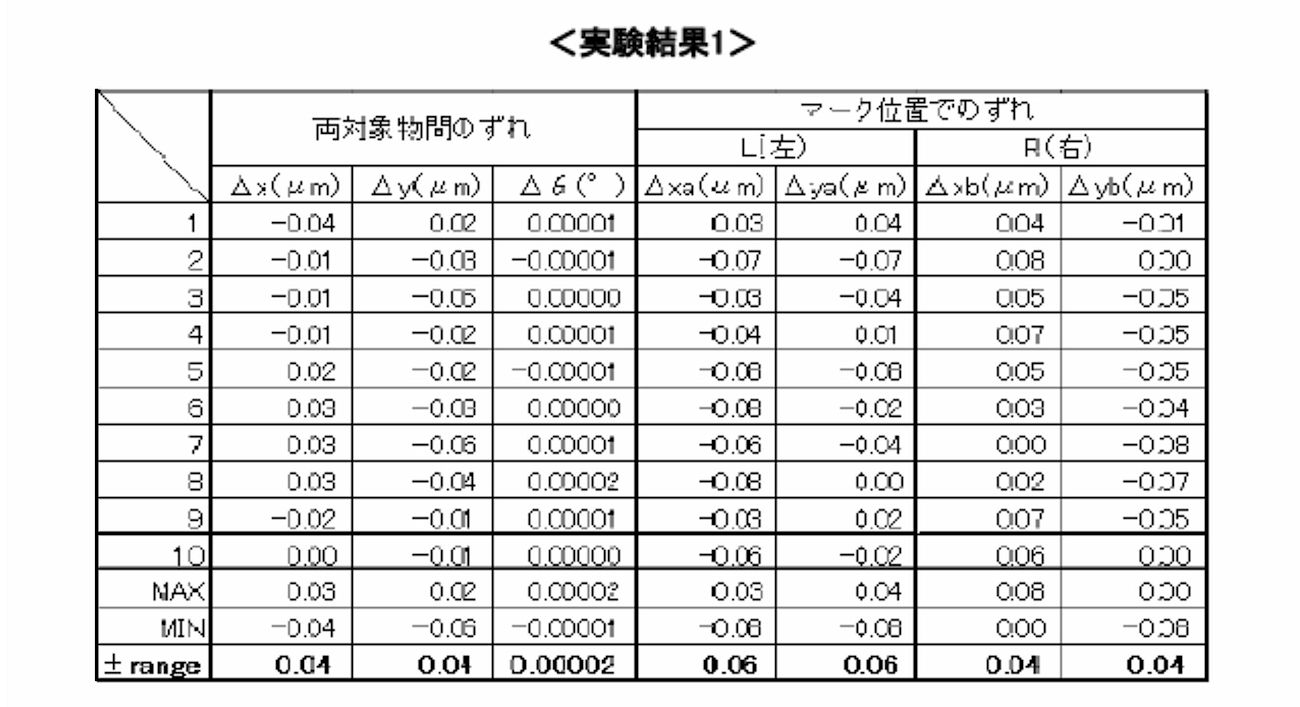
また、上記の接合方法において、前記親水化処理工程と張り合わせ工程の間に、前記第一の基板と前記第二の基板とを、前記接合面同士を対向させて配置し、前記第一の基板と前記第二の基板との位置ずれ量を測定して、前記第一の基板と前記第二の基板との位置ずれ量が小さくなるように前記第一の基板と前記第二の基板との相対位置を調整する工程、をさらに備える。
In the above bonding method, the first substrate and the second substrate are arranged with the bonding surfaces facing each other between the hydrophilization treatment step and the bonding step, and the first substrate Between the first substrate and the second substrate so that the amount of positional deviation between the first substrate and the second substrate is small. A step of adjusting the relative position.
また、上記の接合方法において、前記張り合わせ工程の間又は後に、前記第一の基板と前記第二の基板との位置ずれ量を測定する工程をさらに備える。前記張り合わせ工程の間、すなわち全面の接合が完了する前に位置ずれを測定して、基板同士を離間させることで、張り合わせ工程ないし相対位置の調整工程を繰り返し行うことができる。このため、基板間の相対位置の位置合わせの精度をより高めることができる。
Further, the above bonding method further includes a step of measuring a positional shift amount between the first substrate and the second substrate during or after the bonding step. By measuring the positional deviation during the bonding process, that is, before the bonding of the entire surface is completed, and separating the substrates, the bonding process or the relative position adjusting process can be repeated. For this reason, the precision of alignment of the relative positions between the substrates can be further increased.
測定された前記位置ずれ量が許容誤差範囲を超えている場合には、前記中央部同士が一定の距離を保つように突き合わせた状態で、前記第一の基板の外周部と前記第二の基板の外周部との距離を離し、次いで、前記第一の基板の中央部の撓みを戻す工程と、前記第一の基板と前記第二の基板との位置ずれ量が小さくなるように前記第一の基板と前記第二の基板との相対位置を調整する工程とをさらに備え、前記位置ずれ量が許容誤差範囲内に収まるまで、前記第一の基板を前記接合面の外周部に対して中央部が前記第二の基板側に突出するように撓ませる工程から、前記第一の基板と前記第二の基板との相対位置を調整する工程までを繰り返す。
When the measured amount of positional deviation exceeds the allowable error range, the outer peripheral portion of the first substrate and the second substrate are in contact with each other so that the central portions keep a constant distance. And the step of returning the deflection of the central portion of the first substrate, and the first substrate and the second substrate so that the positional deviation amount is small. Adjusting the relative position of the substrate and the second substrate, and the first substrate is centered with respect to the outer peripheral portion of the bonding surface until the amount of displacement is within an allowable error range. The process from the step of bending so that the portion protrudes toward the second substrate side to the step of adjusting the relative position between the first substrate and the second substrate is repeated.
図1は、本発明の一実施形態に係る基板接合装置100の内部の概略構造を示す正面図である。図2は、ステージ及びヘッド付近を示す概略斜視図である。図3は、基板を保持したステージの構成を示す正断面図である。図7は、突出機構の他の例を示す正断面図である。なお、以下の説明においては、便宜上、XYZ直交座標系を用いて方向などを示している。
FIG. 1 is a front view showing a schematic structure inside a substrate bonding apparatus 100 according to an embodiment of the present invention. FIG. 2 is a schematic perspective view showing the vicinity of the stage and the head. FIG. 3 is a front sectional view showing the configuration of the stage holding the substrate. FIG. 7 is a front sectional view showing another example of the protruding mechanism. In the following description, directions and the like are shown using an XYZ orthogonal coordinate system for convenience.
図1に示すように、基板接合装置100は、チャンバ200と、被接合物である基板(第二の基板)301,基板(第一の基板)302を対向して支持する基板支持手段400と、基板301,302の相対的位置関係を測定する位置測定手段(位置合わせ部)500と、対向して支持された基板301,302の表面に対して表面活性化処理を施す親水化処理手段600と、基板接合装置100の各部の動作を制御するコントローラ(制御部)700と、を備えている。基板301、302としては、例えば、ガラス基板や酸化物基板(例えば、酸化ケイ素(SiO2)基板やアルミナ基板(Al2O3))、窒化物基板(例えば、窒化ケイ素(SiN)、窒化アルミニウム(AlN))のいずれかからなる。
As shown in FIG. 1, the substrate bonding apparatus 100 includes a chamber 200, a substrate (second substrate) 301 that is an object to be bonded, and a substrate support unit 400 that supports the substrate (first substrate) 302 so as to face each other. , A position measuring means (positioning unit) 500 for measuring the relative positional relationship between the substrates 301 and 302, and a hydrophilic treatment means 600 for performing a surface activation process on the surfaces of the substrates 301 and 302 that are supported to face each other. And a controller (control unit) 700 that controls the operation of each unit of the substrate bonding apparatus 100. Examples of the substrates 301 and 302 include a glass substrate, an oxide substrate (for example, a silicon oxide (SiO 2 ) substrate, an alumina substrate (Al 2 O 3 )), a nitride substrate (for example, silicon nitride (SiN), and aluminum nitride. (AlN)).
<チャンバ>
チャンバ200は、中空箱状で、その内部に、後述する基板支持手段400のステージ401,402などが設けられている。チャンバ200は、内部を真空引きするための真空引き手段として、真空ポンプ201を備えている。真空ポンプ201は、排気管202を介してチャンバ200に接続されている。排気管202には、排気管202を開閉する排気弁203が設けられている。 <Chamber>
Thechamber 200 has a hollow box shape, and stages 401 and 402 of a substrate support means 400 described later are provided therein. The chamber 200 includes a vacuum pump 201 as a evacuation unit for evacuating the inside. The vacuum pump 201 is connected to the chamber 200 via the exhaust pipe 202. The exhaust pipe 202 is provided with an exhaust valve 203 that opens and closes the exhaust pipe 202.
チャンバ200は、中空箱状で、その内部に、後述する基板支持手段400のステージ401,402などが設けられている。チャンバ200は、内部を真空引きするための真空引き手段として、真空ポンプ201を備えている。真空ポンプ201は、排気管202を介してチャンバ200に接続されている。排気管202には、排気管202を開閉する排気弁203が設けられている。 <Chamber>
The
このようなチャンバ200は、排気管202を開くとともに、真空ポンプ201を作動させることによって、排気管202を通してチャンバ200内の気体を外部に排出する。これによりチャンバ200内は減圧されて真空引きされ、チャンバ200内の雰囲気は真空又は低圧状態にされる。また、排気弁203は、その開閉量を変動させることで、排気管202における排気流量を調整し、チャンバ200内の目的の真空度に調整することができる。
In such a chamber 200, the exhaust pipe 202 is opened and the vacuum pump 201 is operated to discharge the gas in the chamber 200 to the outside through the exhaust pipe 202. As a result, the inside of the chamber 200 is depressurized and evacuated, and the atmosphere in the chamber 200 is brought into a vacuum or low pressure state. Further, the exhaust valve 203 can adjust the exhaust flow rate in the exhaust pipe 202 by changing the opening / closing amount thereof, and can adjust the target vacuum degree in the chamber 200.
<距離測定手段>
基板301又は302の中央部を撓ませる工程の前に、基板301,302を保持するステージ(第二基板保持部)401とステージ(第一基板保持部)402との距離を測定する距離測定手段(図示せず)を備える。距離測定手段は、例えばレーザー距離計などステージに接触せずにステージ間の距離を測れるものが好ましい。 <Distance measuring means>
Distance measuring means for measuring the distance between the stage (second substrate holding unit) 401 holding the substrates 301 and 302 and the stage (first substrate holding unit) 402 before the step of bending the central portion of the substrate 301 or 302. (Not shown). The distance measuring means is preferably a device that can measure the distance between stages without contacting the stage, such as a laser distance meter.
基板301又は302の中央部を撓ませる工程の前に、基板301,302を保持するステージ(第二基板保持部)401とステージ(第一基板保持部)402との距離を測定する距離測定手段(図示せず)を備える。距離測定手段は、例えばレーザー距離計などステージに接触せずにステージ間の距離を測れるものが好ましい。 <Distance measuring means>
Distance measuring means for measuring the distance between the stage (second substrate holding unit) 401 holding the
<ウエハ厚み測定手段>
基板301又は302の中央部を撓ませる工程の前に、各基板301,302の厚みを測定するウエハ厚み測定手段(図示せず)を備える。ウエハ厚み測定手段は、例えばレーザー変位計など基板に接触せずに基板の厚みを測れるものが好ましい。本実施形態では、アライナ位置にて上下からレーザーでウエハ厚みを3ヵ所測定する。また、円周上や全面を測定して必要な厚みを計算して求めても良い。 <Wafer thickness measuring means>
Prior to the step of bending the central portion of the substrate 301 or 302, a wafer thickness measuring means (not shown) for measuring the thickness of each of the substrates 301 and 302 is provided. The wafer thickness measuring means is preferably capable of measuring the thickness of the substrate without contacting the substrate, such as a laser displacement meter. In the present embodiment, the wafer thickness is measured at three locations with a laser from above and below at the aligner position. Alternatively, the required thickness may be calculated by measuring the circumference or the entire surface.
基板301又は302の中央部を撓ませる工程の前に、各基板301,302の厚みを測定するウエハ厚み測定手段(図示せず)を備える。ウエハ厚み測定手段は、例えばレーザー変位計など基板に接触せずに基板の厚みを測れるものが好ましい。本実施形態では、アライナ位置にて上下からレーザーでウエハ厚みを3ヵ所測定する。また、円周上や全面を測定して必要な厚みを計算して求めても良い。 <Wafer thickness measuring means>
Prior to the step of bending the central portion of the
上記の距離測定手段とウエハ厚み測定手段の測定結果より基板301と302との距離を算出することができる。ここで、基板301と302との距離とは、基板301と302の接合面間の距離であり、上記の測定手段によって測定されたステージ(第二基板保持部)401とステージ(第一基板保持部)402との距離から、上記のウエハ厚み測定手段によって測定された各基板301,302の厚みを引いた距離として算出することができる。
The distance between the substrates 301 and 302 can be calculated from the measurement results of the distance measuring means and the wafer thickness measuring means. Here, the distance between the substrates 301 and 302 is the distance between the bonding surfaces of the substrates 301 and 302, and the stage (second substrate holding unit) 401 and the stage (first substrate holding) measured by the measurement means described above. Part) 402, and can be calculated as a distance obtained by subtracting the thickness of each of the substrates 301 and 302 measured by the wafer thickness measuring means.
<基板支持手段>
基板支持手段400は、基板301,302を支持するステージ(第二基板保持部)401,ステージ(第一基板保持部)402と、それぞれのステージを移動させるステージ駆動機構403,404と、基板を加熱する基板加熱手段420と、を備えている。 <Substrate support means>
The substrate support means 400 includes a stage (second substrate holding unit) 401, a stage (first substrate holding unit) 402 for supporting the substrates 301 and 302, stage driving mechanisms 403 and 404 for moving the respective stages, and a substrate. Substrate heating means 420 for heating.
基板支持手段400は、基板301,302を支持するステージ(第二基板保持部)401,ステージ(第一基板保持部)402と、それぞれのステージを移動させるステージ駆動機構403,404と、基板を加熱する基板加熱手段420と、を備えている。 <Substrate support means>
The substrate support means 400 includes a stage (second substrate holding unit) 401, a stage (first substrate holding unit) 402 for supporting the
ステージ401,402は、上下方向(Z方向)において互いに対向するよう設けられている。下側のステージ401は、その上面が基板301の支持面とされている。上側のステージ402は、その下面が基板302の支持面とされている。これらステージ401,402は、支持面同士が互いに平行に配置されている。
Stages 401 and 402 are provided to face each other in the vertical direction (Z direction). The upper surface of the lower stage 401 is a support surface of the substrate 301. The lower surface of the upper stage 402 is a support surface of the substrate 302. The support surfaces of these stages 401 and 402 are arranged in parallel to each other.
ステージ401,402は、それぞれの支持面に、機械式チャック、静電チャック、真空チャックなどの保持機構を有していてもよい。この保持機構は、基板301,302の支持面への固定状態と、基板301,302の支持面への固定からの開放状態とを切り換えることができる。
The stages 401 and 402 may have a holding mechanism such as a mechanical chuck, an electrostatic chuck, or a vacuum chuck on each support surface. This holding mechanism can switch between a fixed state of the substrates 301 and 302 to the support surface and an open state from the fixed state of the substrates 301 and 302 to the support surface.
下側のステージ401は、ステージ駆動機構403を備えている。ステージ駆動機構403は、ステージ401とステージ402とが互いに対向する上下方向(Z方向)に直交する水平面内で、下側のステージ401をXYθ方向に移動させる。
The lower stage 401 includes a stage drive mechanism 403. The stage drive mechanism 403 moves the lower stage 401 in the XYθ direction within a horizontal plane orthogonal to the vertical direction (Z direction) in which the stage 401 and the stage 402 face each other.
上側のステージ402は、ステージ駆動機構404として、Z方向昇降駆動機構406と、Z軸周り回転駆動機構407と、を備えている。ステージ駆動機構404は、XY方向駆動機構405をさらに備えることもできる。
The upper stage 402 includes a Z-direction lifting drive mechanism 406 and a Z-axis rotation drive mechanism 407 as the stage drive mechanism 404. The stage drive mechanism 404 can further include an XY direction drive mechanism 405.
Z方向昇降駆動機構406は、ステージ402を、Z方向に移動させることによって、ステージ401,402をZ方向に沿って互いに接近又は離間させる。また、Z方向昇降駆動機構406は、両ステージ401,402同士を接近させることで、保持した基板301,302の対向する接合面同士を接触させ、さらに互いに接触した基板301,302同士を加圧することができる。
The Z-direction lifting / lowering drive mechanism 406 moves the stage 402 in the Z direction, thereby moving the stages 401 and 402 closer to or away from each other along the Z direction. Further, the Z-direction lifting drive mechanism 406 brings the stages 401 and 402 close to each other to bring the bonded surfaces of the held substrates 301 and 302 into contact with each other, and further pressurizes the substrates 301 and 302 that are in contact with each other. be able to.
Z方向昇降駆動機構406には、そのZ軸に係る力を測定する圧力センサ408が設けられている。圧力センサ408は、Z方向昇降駆動機構406により互いに加圧される基板301,302の接合面に作用する圧力を検知する。圧力センサ408には、例えばロードセルを用いることができる。
The Z direction elevating drive mechanism 406 is provided with a pressure sensor 408 for measuring a force related to the Z axis. The pressure sensor 408 detects the pressure acting on the bonding surfaces of the substrates 301 and 302 that are pressed against each other by the Z-direction lift drive mechanism 406. For example, a load cell can be used as the pressure sensor 408.
Z方向昇降駆動機構406により、基板301と302の中央部同士が非接合状態を維持する圧力で突き合わせた状態、あるいは、基板301の中央部と基板302の中央部の距離を保った状態で、基板301の外周部と基板302の外周部との距離を縮め、基板301の接合面と基板302の接合面とが、接合面の全面で突き合わされるように移動することができる。
In a state where the central portions of the substrates 301 and 302 are abutted with each other by a pressure that maintains the non-bonded state by the Z-direction lifting drive mechanism 406, or in a state where the distance between the central portion of the substrate 301 and the central portion of the substrate 302 is maintained The distance between the outer peripheral portion of the substrate 301 and the outer peripheral portion of the substrate 302 can be reduced, and the bonding surface of the substrate 301 and the bonding surface of the substrate 302 can be moved so as to abut on the entire bonding surface.
XY方向駆動機構405は、ステージ401とステージ402とが互いに対向するZ方向に直交するXY方向で、ステージ402をスライド移動させることができる。
The XY direction drive mechanism 405 can slide the stage 402 in the XY direction orthogonal to the Z direction where the stage 401 and the stage 402 face each other.
図1及び図2に示すように、XY方向駆動機構405とステージ402との間には、ステージ402の外周部近傍に、周方向に間隔をあけて、複数、例えば3つの突出機構412が設けられている。突出機構412は、それぞれ独立にZ方向に伸縮駆動される。これら突出機構412により、基板301,302の接合面に作用する力又は圧力の分布を微細又は正確に調節する。
As shown in FIGS. 1 and 2, between the XY direction drive mechanism 405 and the stage 402, a plurality of, for example, three projecting mechanisms 412 are provided in the vicinity of the outer periphery of the stage 402 at intervals in the circumferential direction. It has been. The protruding mechanisms 412 are independently extended and contracted in the Z direction. By these protrusion mechanisms 412, the distribution of force or pressure acting on the bonding surfaces of the substrates 301 and 302 is finely or accurately adjusted.
また、各突出機構412とXY方向駆動機構405との間には、それぞれステージ圧力センサ411が備えられている。突出機構412は、図示しない制御部により、複数のステージ圧力センサ411で測定した、基板301,302の接合面に作用する力又は圧力の分布に応じてその作動が制御される。これらステージ圧力センサ411及び突出機構412は、Z方向昇降駆動機構406によって、互いに加圧された接触した基板301,302に作用する圧力の分布を、さらに微細に調整し、その接合面に亘って均一又は所定の分布とすることができる。
Further, a stage pressure sensor 411 is provided between each protrusion mechanism 412 and the XY direction drive mechanism 405. The operation of the protruding mechanism 412 is controlled by a control unit (not shown) according to the distribution of force or pressure acting on the bonding surfaces of the substrates 301 and 302 measured by the plurality of stage pressure sensors 411. The stage pressure sensor 411 and the protrusion mechanism 412 further finely adjust the distribution of pressure acting on the substrates 301 and 302 that are pressed against each other by the Z-direction lift drive mechanism 406, and extend over the joint surface. It can be a uniform or predetermined distribution.
本発明の一実施形態では、基板301の接合面と基板302の接合面に生じる圧力に基づいて、基板301の外周部と基板302の外周部との距離を縮める速度、すなわちZ方向昇降駆動機構406の動作速度を調整することが好ましい。このような構成とすることで、基板301の接合面と基板302の接合面に生じる圧力を一定の力に維持することができる。
In one embodiment of the present invention, the speed at which the distance between the outer peripheral portion of the substrate 301 and the outer peripheral portion of the substrate 302 is reduced based on the pressure generated on the bonding surface of the substrate 301 and the bonding surface of the substrate 302, that is, the Z-direction lift drive mechanism It is preferable to adjust the operation speed of 406. With such a structure, the pressure generated on the bonding surface of the substrate 301 and the bonding surface of the substrate 302 can be maintained at a constant force.
又は、基板301の接合面と基板302の接合面に生じる圧力に基づいて、Z方向昇降駆動機構406の動作を止めてもよい。基板301の接合面と基板302の接合面に生じる圧力が一定値を超えた場合、例えば、基板を相手側基板に対して押圧する方向を正とした場合に、基板の接合面に生じる圧力が大きく負の値となったときは、基板同士が互いに距離を縮めようとする力が働いていると考えられる。このような状態で基板間の距離を縮めることにより、X又はY方向に生じる力で基板が変形する虞がある。このような変形が生じると、接合された基板同士の位置ずれが起こる。
Alternatively, the operation of the Z-direction lifting drive mechanism 406 may be stopped based on the pressure generated on the bonding surface of the substrate 301 and the bonding surface of the substrate 302. When the pressure generated on the bonding surface of the substrate 301 and the bonding surface of the substrate 302 exceeds a certain value, for example, when the direction in which the substrate is pressed against the counterpart substrate is positive, the pressure generated on the bonding surface of the substrate is When the value is greatly negative, it is considered that a force is working to reduce the distance between the substrates. By reducing the distance between the substrates in such a state, the substrates may be deformed by a force generated in the X or Y direction. When such deformation occurs, positional displacement between the bonded substrates occurs.
基板301の接合面と基板302の接合面に生じる圧力を一定の力に維持しつつ、この圧力が一定値を超えた場合に、Z方向昇降駆動機構406の動作を止めることで、時間が経つと、基板同士が互いに距離を縮めようとする力が緩和され、一定値以下に戻る。基板の接合面に生じる圧力が一定値以下に戻った時点で、再度Z方向昇降駆動機構406を再駆動させることができる。
By maintaining the pressure generated on the bonding surface of the substrate 301 and the bonding surface of the substrate 302 at a constant force and stopping the operation of the Z-direction lifting drive mechanism 406 when this pressure exceeds a certain value, time passes. Then, the force to reduce the distance between the substrates is alleviated and returns to a certain value or less. When the pressure generated on the bonding surface of the substrates returns to a certain value or less, the Z-direction lift drive mechanism 406 can be re-driven again.
また本発明の一実施形態では、基板を相手側基板に対して押圧する方向を正とした場合に、基板の接合面に生じる圧力が負の値にならないように維持しながら、基板の接合面に生じる圧力を保つことがより好ましい。一例としては、基板の接合面に生じる圧力の下限値を-100Nと設定した場合、検知される圧力が-150N以下になったときには、動作速度をコントロールするか一時的に動作を止めるようにする。これは、基板間の距離を縮めるときと剥がすときの双方に適用できる。
Moreover, in one embodiment of the present invention, when the direction in which the substrate is pressed against the counterpart substrate is positive, the bonding surface of the substrate is maintained so that the pressure generated on the bonding surface of the substrate does not become a negative value. It is more preferable to maintain the pressure generated in As an example, when the lower limit value of the pressure generated on the bonding surface of the substrate is set to −100 N, the operation speed is controlled or the operation is temporarily stopped when the detected pressure becomes −150 N or less. . This can be applied both when the distance between the substrates is reduced and when the distance is removed.
本発明の一実施形態では、基板の接合面に生じる圧力を、複数のステージ圧力センサ411で検知することができる。これにより、基板301又は302に厚みのバラツキやゆがみがあっても、基板間に生じる圧力による変形を抑制することができる。
In one embodiment of the present invention, the pressure generated on the bonding surface of the substrates can be detected by a plurality of stage pressure sensors 411. Thereby, even if the substrate 301 or 302 has thickness variation or distortion, deformation due to pressure generated between the substrates can be suppressed.
また、Z方向昇降駆動機構406を上昇させ、基板301の外周部と基板302の外周部との距離を離すときにも、基板の接合面に生じる圧力が一定の値を上回らないように維持するようにしてもよい。
Further, even when the Z-direction lifting / lowering drive mechanism 406 is raised to increase the distance between the outer peripheral portion of the substrate 301 and the outer peripheral portion of the substrate 302, the pressure generated on the bonding surface of the substrate is maintained so as not to exceed a certain value. You may do it.
Z軸周り回転駆動機構407は、ステージ402をZ軸周りに回転させることができる。回転駆動機構407により、ステージ402をステージ401に対するZ軸周りの回転位置θを制御して、両基板301,302の回転方向の相対的位置を制御することができる。
The Z axis rotation drive mechanism 407 can rotate the stage 402 around the Z axis. The rotational drive mechanism 407 can control the rotational position θ around the Z axis with respect to the stage 401 with respect to the stage 401, thereby controlling the relative positions of both substrates 301 and 302 in the rotational direction.
制御部は、撓ませた第一の基板を解放するに先立ち、チャンバ内で第一の基板および第二の基板の周囲の雰囲気を真空引きすることで空気の噛みこみによるボイドなく張り合わせることが可能となる。
Prior to releasing the bent first substrate, the control unit evacuates the atmosphere around the first substrate and the second substrate in the chamber so that the air can be bonded without voids. It becomes possible.
ハイブリッドボンディングと呼ばれる微小電極と周辺の絶縁層を同時に接合する分野においては、Cuからなる微小電極部を中凹状にへこました状態にCMP研磨して先に150℃程度の低温で絶縁層を接合させた後、350℃程度まで加熱することでCu電極を膨張させ隙間を埋めてCu同士を拡散接合させる手法がある。この手法において大気中で接合するとCu電極間の隙間は大気で埋められており、加熱膨張過程においてCu電極表面は酸化してしまい接合上好ましくない。また、隙間の空気は行きどころがないためボイドとして残る。基板の構成材料となるSiO2以外に、Cu電極を接合面に含む場合には、接合工程において加熱及び加圧を加えることがより好ましい。
In the field where the microelectrode called hybrid bonding and the surrounding insulating layer are bonded at the same time, the microelectrode portion made of Cu is subjected to CMP polishing in a dented state, and the insulating layer is first bonded at a low temperature of about 150 ° C. Then, there is a method in which the Cu electrodes are expanded by heating to about 350 ° C. to fill the gaps and diffusely bond Cu to each other. When joining in the atmosphere in this method, the gap between the Cu electrodes is filled with the atmosphere, and the surface of the Cu electrode is oxidized in the heating and expansion process, which is not preferable for joining. In addition, the air in the gap remains void as it has nowhere to go. In addition to SiO 2 which is a constituent material of the substrate, when a Cu electrode is included in the bonding surface, it is more preferable to apply heat and pressure in the bonding step.
本実施形態に係る接合装置では、真空中で接合することで隙間は真空であり、酸化を抑制でき、また、ボイドの発生も抑制できる。真空引きのタイミングとしては、中央部を接触させた状態では大気環境を確保することにより接触部に水分子が多く存在するため位置ずれを補正することが可能となるが、数分以内の短い時間で、かつ、数100Pa程度の真空度であれば最初から真空引きしていてもある程度界面に水分子を残すことも可能となる。
In the bonding apparatus according to the present embodiment, the gap is vacuumed by bonding in vacuum, so that oxidation can be suppressed and generation of voids can also be suppressed. As for the timing of evacuation, it is possible to correct misalignment because there are many water molecules in the contact part by securing the atmospheric environment in the state where the center part is in contact, but it is a short time within a few minutes In addition, if the degree of vacuum is about several hundred Pa, it is possible to leave water molecules at the interface to some extent even if vacuuming is performed from the beginning.
また、中央部を接触させる直前に真空引きすることで水分子を介在させながら全面を真空雰囲気に確保することができる。また、接触後の位置補正を必要としない場合は最初から真空に引いておいてもよい。
Also, by vacuuming immediately before contacting the central portion, the entire surface can be secured in a vacuum atmosphere while interposing water molecules. If position correction after contact is not required, a vacuum may be drawn from the beginning.
また、第一の基板と第二の基板との位置合わせ工程は、撓ませた基板の解放前でもよいし、真空引きの後でもよい。位置合わせに要する時間は、数秒~数十秒であり、基板の接合に影響は出ない。
In addition, the alignment process between the first substrate and the second substrate may be performed before releasing the bent substrate or after evacuation. The time required for alignment is several seconds to several tens of seconds, and does not affect the bonding of the substrates.
本発明の一実施形態では、基板の中央部を撓ませる工程の前に、基板301(又は基板302)のいずれかのみを保持した状態で、基板を保持していないステージ402(又はステージ401)と保持された基板との間の距離を測定する距離測定手段(図示せず)を備えてもよい。
In one embodiment of the present invention, a stage 402 (or stage 401) not holding a substrate while holding only one of the substrates 301 (or substrate 302) before the step of bending the central portion of the substrate. And a distance measuring means (not shown) for measuring the distance between the substrate and the held substrate.
距離測定手段は、例えばステージ402(又はステージ401)内部に設けられたレーザー距離計であって、対向するステージ又は基板に接触せずに対向ステージ又は基板上面からステージまでの距離を測れるものが好ましい。上記の距離測定手段とウエハ厚み測定手段の測定結果より基板301と302との距離を算出することができる。例えばヘッド側上ガラスステージの上部からレーザ光を投入して下ガラスステージ上面の反射光と上ガラスステージ下側表面の反射光の差分からステージ間距離を求めることができる。また、下ステージ上にウエハが乗っている場合には上ガラスステージ下側表面と下ウエハ上面との距離を求めることができる。
The distance measuring means is preferably a laser distance meter provided in the stage 402 (or stage 401), for example, and can measure the distance from the opposing stage or the upper surface of the substrate to the stage without contacting the opposing stage or substrate. . The distance between the substrates 301 and 302 can be calculated from the measurement results of the distance measuring means and the wafer thickness measuring means. For example, it is possible to obtain the inter-stage distance from the difference between the reflected light on the upper surface of the lower glass stage and the reflected light on the lower surface of the upper glass stage by introducing laser light from the upper part of the head side upper glass stage. When the wafer is on the lower stage, the distance between the lower surface of the upper glass stage and the upper surface of the lower wafer can be obtained.
また本発明の一実施形態では、基板301と基板302をステージ401、402上に保持した状態で、基板301と基板302の接合面の距離を測定する距離測定手段(図示せず)を備えてもよい。具体的には、基板間に基板301と基板302の接合面の距離を測定できる距離測定手段を挿入して、基板間の距離を測定する態様が挙げられる。
In one embodiment of the present invention, distance measuring means (not shown) is provided for measuring the distance between the bonding surfaces of the substrate 301 and the substrate 302 in a state where the substrate 301 and the substrate 302 are held on the stages 401 and 402. Also good. Specifically, a mode in which a distance measuring unit capable of measuring the distance between the bonding surfaces of the substrate 301 and the substrate 302 is inserted between the substrates to measure the distance between the substrates can be mentioned.
<突出機構>
図3に示すように、上側のステージ402において、基板302を支持する支持面の中央部には、下側のステージ401側に向けて出没可能な突出機構430が内蔵されている。この突出機構430は、シリンダ構造、電磁式の機構を採用することができる。突出機構430は、少なくとも、基板302を撓ませる力を有し、突出する方向と逆向きの力を一定以上受けると、突出する方向と逆向きに移動可能な機能を備えるものが好ましい。 <Projecting mechanism>
As shown in FIG. 3, in theupper stage 402, a protruding mechanism 430 that can be projected and retracted toward the lower stage 401 side is built in the central portion of the support surface that supports the substrate 302. The protruding mechanism 430 can employ a cylinder structure or an electromagnetic mechanism. It is preferable that the protrusion mechanism 430 has at least a force that bends the substrate 302 and has a function of moving in a direction opposite to the protruding direction when receiving a force in a direction opposite to the protruding direction for a certain amount.
図3に示すように、上側のステージ402において、基板302を支持する支持面の中央部には、下側のステージ401側に向けて出没可能な突出機構430が内蔵されている。この突出機構430は、シリンダ構造、電磁式の機構を採用することができる。突出機構430は、少なくとも、基板302を撓ませる力を有し、突出する方向と逆向きの力を一定以上受けると、突出する方向と逆向きに移動可能な機能を備えるものが好ましい。 <Projecting mechanism>
As shown in FIG. 3, in the
突出機構430は、図4に示すように、基板302を押圧する押圧部材434と、ボイスコイルモータ433と、変位センサ435と、を有する。ボイスコイルモータ433は、有底筒状のコイルボビン4331と、コイルボビン4331に巻回されたコイル4332と、コイル4332に対向して配置されたマグネット4333と、コイル4332の外側を覆う有底筒状部と有底筒状部の底部からコイル4332の内側に嵌入される突出部とから構成されるヨーク4334と、を有する。押圧部材434は、ボイスコイルモータ433のコイルボビン4331の底部に固定されている。ボイスコイルモータ433のヨーク4334は、ステージ本体4021に固定されている。ボイスコイルモータ433は、コイル4332に電流が流れると、コイルボビン4331がその筒軸方向に沿って移動する。これにより、コイルボビン4331に固定された押圧部材434が、ステージ402から突出する方向またはステージ402に没入する方向へ移動する。そして、コイル4332に流す電流の大きさを制御することにより、コイルボビン4331に固定された押圧部材434により基板302に加える圧力を制御することができる。また、押圧部材434は、ステージ本体4021から外部に突出する突出部4341と、突出部4341と一体に形成された平板状のベース部4342と、を有する。そして、変位センサ435は、例えば渦電流式変位センサから構成され、その検出部435aと、押圧部材434のベース部4342との間の距離LHを計測する。基板接合装置100は、この変位センサ435で測定される距離LHに基づいて、コイルボビン4331に固定された押圧部材434の位置制御を実行することができる。このように、突出機構430が、ボイスコイルモータ433を利用したものであることにより、押圧部材434で基板302を押圧する際の圧力制御並びに押圧部材434の位置制御が可能となっている。例えば、基板接合装置100は、押圧部材434により基板302を押圧しつつ圧力制御を実行しているときに、押圧部材434の位置が予め設定された範囲から外れた場合、押圧部材434の制御を位置制御に切り替えて押圧部材434を予め設定された範囲内に戻すことができる。このように、基板接合装置100は、押圧部材434の圧力制御と位置制御とを組み合わせることが可能となっている。
As shown in FIG. 4, the protruding mechanism 430 includes a pressing member 434 that presses the substrate 302, a voice coil motor 433, and a displacement sensor 435. The voice coil motor 433 includes a bottomed cylindrical coil bobbin 4331, a coil 4332 wound around the coil bobbin 4331, a magnet 4333 disposed to face the coil 4332, and a bottomed cylindrical part covering the outside of the coil 4332. And a yoke 4334 configured from a bottom portion of the bottomed cylindrical portion and a protruding portion fitted inside the coil 4332. The pressing member 434 is fixed to the bottom of the coil bobbin 4331 of the voice coil motor 433. A yoke 4334 of the voice coil motor 433 is fixed to the stage main body 4021. In the voice coil motor 433, when a current flows through the coil 4332, the coil bobbin 4331 moves along the cylinder axis direction. As a result, the pressing member 434 fixed to the coil bobbin 4331 moves in a direction protruding from the stage 402 or a direction immersing in the stage 402. Then, by controlling the magnitude of the current flowing through the coil 4332, the pressure applied to the substrate 302 by the pressing member 434 fixed to the coil bobbin 4331 can be controlled. Further, the pressing member 434 includes a protruding portion 4341 that protrudes from the stage main body 4021 to the outside, and a flat base portion 4342 that is formed integrally with the protruding portion 4341. And the displacement sensor 435 is comprised, for example from an eddy current type displacement sensor, and measures the distance LH between the detection part 435a and the base part 4342 of the press member 434. FIG. The substrate bonding apparatus 100 can execute position control of the pressing member 434 fixed to the coil bobbin 4331 based on the distance LH measured by the displacement sensor 435. As described above, since the protruding mechanism 430 uses the voice coil motor 433, pressure control when the pressing member 434 presses the substrate 302 and position control of the pressing member 434 are possible. For example, when the substrate bonding apparatus 100 performs pressure control while pressing the substrate 302 with the pressing member 434, if the position of the pressing member 434 is out of a preset range, the substrate bonding apparatus 100 controls the pressing member 434. By switching to position control, the pressing member 434 can be returned to a preset range. As described above, the substrate bonding apparatus 100 can combine pressure control and position control of the pressing member 434.
なお、突出機構としては、例えばシリンダ構造を有し、シリンダ内へ供給するエア圧を変化させることにより加圧力を変化させることができるものであってもよい。また、突出機構として、電磁コイル式でありコイルに流れる電流の電流値を変化させることにより加圧力を変化させることができるものであってもよい。
In addition, as a protrusion mechanism, it may have a cylinder structure, for example, and can change a pressurizing force by changing the air pressure supplied in a cylinder. Moreover, as a protrusion mechanism, it is an electromagnetic coil type | mold and can change a applied pressure by changing the electric current value of the electric current which flows into a coil.
撓ませた状態から、ヘッドまたはステージの各基板間の距離を近づける基板間に垂直な移動軸、例えば本実施形態ではZ軸により基板同士を近づけていくことで、突出機構は押し下げられ、外周部を近づけて中央部から円上に接触面積を外周部へと、他方の平坦な基板に倣わせながら増やしていくことができる。
The projecting mechanism is pushed down by bringing the substrates closer to each other by the vertical movement axis between the substrates, for example, the Z axis in this embodiment, to bring the distance between each substrate of the head or stage from the bent state. , And the contact area can be increased from the center to the outer periphery, following the other flat substrate.
また、基板間の距離を数値制御することで濡れ広がりのスピードをコントロールすることができる。表面活性化状況によっては濡れスピードが違い、従来のツメをウエハ間に挿入して引き抜き自然落下させる方法では早すぎるとボイドになったりするため、スピードコントロールすることは有効な方法である。
Also, the speed of wetting and spreading can be controlled by numerically controlling the distance between the substrates. Depending on the surface activation situation, the wetting speed is different, and the conventional method of inserting the claw between the wafers and pulling it out and dropping it naturally causes voids, so speed control is an effective method.
また、両方の基板を撓ませる場合には、片側を数値制御可能なアクチュエータ、例えばピエゾアクチュエータとすれば、ヘッドのZ軸移動に合わせて伸縮させることで、各基板の底面から中央部の距離を上下同じくしながら外周部を近づけて接触面積を外周部へと増やしていくことができる。
When both substrates are bent, if one side is an actuator that can be numerically controlled, for example, a piezo actuator, the distance from the bottom surface of each substrate to the center portion can be expanded and contracted according to the Z-axis movement of the head. The contact area can be increased to the outer peripheral portion by moving the outer peripheral portion closer while maintaining the same upper and lower sides.
この場合、片側のみ撓ませると片側の基板のアライメントマーク位置も内側へずれることになりアライメント精度上もよくなく、かつ、接合時にひずみが生じる。両方向から撓ますことでアライメントマーク位置も同じ位置にくることができ、かつ、接合時のひずみも生じなく張り合わせることが可能となり、従来の片側のみの突出機構に比べて有効な方法である。
In this case, if only one side is bent, the alignment mark position of the substrate on one side is also shifted inward, resulting in poor alignment accuracy and distortion during joining. By bending from both directions, the alignment mark position can be brought to the same position, and bonding can be performed without causing distortion at the time of joining, which is an effective method compared to a conventional one-side protruding mechanism.
例えば片側では20μm必要であった突出量は両側では各10μmで納めることができ、よりひずみが少なくなる。また、特にサブミクロンの精度を必要とされるハイブリッドボンディングと呼ばれる微小電極と周辺の絶縁層を同時に接合する分野、例えばCMOSイメージセンサやメモリ、演算素子、MEMSにおいては特に有効な方法である。
For example, the amount of protrusion that required 20 μm on one side can be accommodated at 10 μm on both sides, resulting in less distortion. In particular, this method is particularly effective in the field of simultaneously bonding a microelectrode called a hybrid bonding that requires submicron accuracy and a peripheral insulating layer, for example, a CMOS image sensor, a memory, an arithmetic element, and a MEMS.
また、中央部を接触させた後、基板の両端マークを画像処理装置で読み取り位置ずれ量を測定後、補正移動させる場合、両基板間の界面に水分子が存在し、加圧力が小さい場合は接触状態のまま補正移動させることができるが、接触面積が大きな場合などは一度突出機構を引き戻して両基板間に隙間を設けて補正移動させる場合もある。また、突出機構はそのままでZ軸移動により隙間を設けることもできる。また、両方を使用して隙間を設けることもできる。
In addition, when the center part is contacted, both end marks of the substrate are read with an image processing device, and the amount of displacement is corrected and then moved for correction.If water molecules exist at the interface between the two substrates and the applied pressure is small, Although the correction movement can be performed in the contact state, when the contact area is large, the protrusion mechanism may be pulled back once to provide a correction movement with a gap between both substrates. Further, it is possible to provide a gap by moving the Z-axis without changing the protruding mechanism. Moreover, a clearance gap can also be provided using both.
図5は、ステージ402に備えた突出機構430により基板302を撓ませた状態を示す正断面図である。図5に示すように、突出機構430をステージ402から突出させると、基板302の外周部302sは、自重により下方向への力を受け、基板302の中央部302cが上方に凸となるように撓む。なお、「突出機構430をステージ402から突出させる」とは、詳細には突出機構430の押圧部材434をステージ402から突出させることを意味する。以後、本明細書において同様である。突出機構430による押圧を解除するか、あるいは、基板302が対抗する基板301に突き合わされて一定以上の力を受けると、基板302は元の平板状の形状に復元する。
FIG. 5 is a front sectional view showing a state in which the substrate 302 is bent by the protruding mechanism 430 provided in the stage 402. As shown in FIG. 5, when the protrusion mechanism 430 is protruded from the stage 402, the outer peripheral portion 302s of the substrate 302 receives a downward force due to its own weight so that the central portion 302c of the substrate 302 protrudes upward. Bend. Note that “protruding mechanism 430 protrudes from stage 402” means that the pressing member 434 of the protruding mechanism 430 protrudes from the stage 402 in detail. Hereinafter, the same applies to the present specification. When the pressing by the protruding mechanism 430 is released, or when the substrate 302 is abutted against the opposing substrate 301 and receives a force exceeding a certain level, the substrate 302 is restored to the original flat plate shape.
突出機構430の基板に接触する頭頂部430aは、例えば、図9に示すような曲面形状であってもよい。これにより、基板に局所的な力を加えずに基板を撓ませることができる。また、これにより、基板の位置ずれも抑制することができる。
The top portion 430a that contacts the substrate of the protruding mechanism 430 may have a curved shape as shown in FIG. Thereby, a board | substrate can be bent, without applying a local force to a board | substrate. Moreover, this can also suppress the displacement of the substrate.
本発明の一実施形態では、基板301の外周部301sと基板302の外周部302sとの距離を縮めるときに、先述のような張り合わせ位置の規定方法とは別に、基板301の中央部301cの接合面の、基板301の外周部301sの接合面に対する突出距離だけ、基板301の外周部301sと基板302の外周部302sとの距離を縮めることが好ましい。この実施形態では、好ましくは、突出機構430の突出した距離と同等の距離だけ、基板301の外周部301sと基板302の外周部302sとの距離を縮める。例えば、前述の変位センサ435により測定される突出機構430の押出し量から張り合わせる位置を決定することができる。例えば突き合わせ位置での変位センサ435の検出値を記憶しておき、突出した時の変位センサ435の検出値との差分から突出量を計算することができる。また、上下センタープッシュする場合には上下の突出量を足してやれば良い。Zの下降量は突出量だけ下降させる方法や、変位センサ435の検出値が、予め記憶しておいた突き合わせ位置での変位センサ435の検出値になるまで下降させる方法などがある。上下でのばらつきを考慮して上下を足した値で突き合わせ位置を割り出す方式が好ましい。また、適宜補正量を加えても良い。
In one embodiment of the present invention, when the distance between the outer peripheral portion 301 s of the substrate 301 and the outer peripheral portion 302 s of the substrate 302 is reduced, the bonding of the central portion 301 c of the substrate 301 is performed separately from the method for defining the bonding position as described above. It is preferable to reduce the distance between the outer peripheral portion 301 s of the substrate 301 and the outer peripheral portion 302 s of the substrate 302 by the protruding distance of the surface with respect to the bonding surface of the outer peripheral portion 301 s of the substrate 301. In this embodiment, preferably, the distance between the outer peripheral portion 301 s of the substrate 301 and the outer peripheral portion 302 s of the substrate 302 is reduced by a distance equivalent to the protruding distance of the protruding mechanism 430. For example, the bonding position can be determined from the pushing amount of the protruding mechanism 430 measured by the above-described displacement sensor 435. For example, the detection value of the displacement sensor 435 at the abutting position is stored, and the protrusion amount can be calculated from the difference from the detection value of the displacement sensor 435 when protruding. In addition, when the vertical center push is performed, the vertical protrusion amount may be added. There are a method in which the amount of lowering Z is lowered by the amount of protrusion, and a method in which the detected value of the displacement sensor 435 is lowered until the detected value of the displacement sensor 435 at the pre-stored butt position is reached. A method of determining the abutting position with a value obtained by adding up and down in consideration of the vertical variation is preferable. Further, a correction amount may be added as appropriate.
<保持機構>
ステージ401,402は、それぞれの支持面に、機械式チャック、静電チャック、真空チャックなどの保持機構440を有していてもよい。この保持機構は、基板301,302の支持面への固定状態と、基板301,302の支持面への固定からの開放状態とを切り換えることができる。 <Holding mechanism>
The stages 401 and 402 may have a holding mechanism 440 such as a mechanical chuck, an electrostatic chuck, or a vacuum chuck on each support surface. This holding mechanism can switch between a fixed state of the substrates 301 and 302 to the support surface and an open state from the fixed state of the substrates 301 and 302 to the support surface.
ステージ401,402は、それぞれの支持面に、機械式チャック、静電チャック、真空チャックなどの保持機構440を有していてもよい。この保持機構は、基板301,302の支持面への固定状態と、基板301,302の支持面への固定からの開放状態とを切り換えることができる。 <Holding mechanism>
The
保持機構は、図6に一例を示すように、ステージ401,402の面上において、複数の領域に分割されて設けられてもよい。例えば、図6の例では、外側保持機構440aと内側保持機構440bの二つの保持機構が設けられている。外側保持機構440aと内側保持機構440bは、独立して制御可能であり、外側保持機構440aで基板の外周部を保持しつつ、内側保持機構440bを開放して、基板の中央部においてはZ軸方向に力を受けないようにすることが可能である。
The holding mechanism may be divided into a plurality of regions on the surfaces of the stages 401 and 402 as shown in FIG. For example, in the example of FIG. 6, two holding mechanisms, an outer holding mechanism 440a and an inner holding mechanism 440b, are provided. The outer holding mechanism 440a and the inner holding mechanism 440b can be controlled independently, and the inner holding mechanism 440b is opened while the outer holding mechanism 440a holds the outer peripheral portion of the substrate, and the Z-axis is formed in the central portion of the substrate. It is possible to avoid receiving force in the direction.
保持機構440が複数設けられる場合、例えば、静電チャックと真空チャックなど、原理や機能の異なる保持機構を併用してもよい。例えば、静電チャックの電極と真空チャックの吸着溝がステージの径方向に交互に設けられてもよい。
When a plurality of holding mechanisms 440 are provided, for example, holding mechanisms having different principles and functions, such as an electrostatic chuck and a vacuum chuck, may be used in combination. For example, electrostatic chuck electrodes and vacuum chuck suction grooves may be provided alternately in the radial direction of the stage.
上記の構成に加え、下側のステージ401側に、突出機構430と同様の機構を有するようにしてもよい。図7のように、ステージ401及び402の双方で、基板301及び302を撓ませる構成とすることにより、基板の撓み量が少なくなり、より誤差を少なく基板の位置合わせを行うことができる。
In addition to the above configuration, a mechanism similar to the protruding mechanism 430 may be provided on the lower stage 401 side. As shown in FIG. 7, by adopting a configuration in which the substrates 301 and 302 are bent by both the stages 401 and 402, the amount of bending of the substrate is reduced, and the substrate can be aligned with less error.
下側の基板301を撓ませる場合、基板301の外周部301sのみを保持することが好ましい。この場合、基板301の外周部301sのみを外側の保持機構440aにより保持することで、突出機構430で基板を押圧する力が弱くても、所望の形状に基板が撓むので好ましい。
When the lower substrate 301 is bent, it is preferable to hold only the outer peripheral portion 301 s of the substrate 301. In this case, it is preferable that only the outer peripheral portion 301s of the substrate 301 is held by the outer holding mechanism 440a because the substrate bends to a desired shape even if the force of pressing the substrate by the protruding mechanism 430 is weak.
上記の接合装置において、保持機構440が、真空吸着方式である場合、ステージ上に設けられた吸着溝が基板の箇所によって分離されていてもよい。例えば、基板の周辺部を保持する吸着溝と基板の中央部を保持する吸着溝とが分離され、それぞれが別個に作動してもよい。これにより、基板の外周部のみ保持することができる。
In the above bonding apparatus, when the holding mechanism 440 is a vacuum suction method, the suction groove provided on the stage may be separated by the location of the substrate. For example, the suction groove for holding the peripheral portion of the substrate and the suction groove for holding the central portion of the substrate may be separated and each may operate separately. Thereby, only the outer peripheral part of a board | substrate can be hold | maintained.
また、中央部は最初、真空吸着しておき、撓ます時点で真空破壊して大気圧としたり0.数秒だけ加圧エアを放出して基板をはがれやすくしたりすることができる。また、基板が鏡面ではがれにくい場合は、保持部接触面をあえて粗くすることで、高さ精度を保持したまま、はがれやすくすることもできる。
Also, the central part is first vacuum-adsorbed, and when it bends, it breaks down to the atmospheric pressure. The substrate can be easily peeled off by releasing pressurized air for a few seconds. In addition, when the substrate is difficult to peel off at the mirror surface, it is possible to make it easy to peel off while maintaining the height accuracy by intentionally roughening the holding portion contact surface.
また、接合が完了した基板接合体は、反りや厚みのバラツキを有する場合があるが、下側ステージ401の全面を、再度真空吸着することで、基板接合体の反りや厚みのバラツキを減少させることができる。
In addition, the bonded substrate assembly may have variations in warpage and thickness. However, the entire surface of the lower stage 401 is again vacuum-sucked to reduce warpage and thickness variations in the substrate assembly. be able to.
上記の接合装置において、保持機構440が、静電チャック方式である場合、保持機構は、図6に一例を示すように、ステージ401,402の面上において、複数の領域に分割されて設けられてもよい。例えば、図6の例では、外側保持機構440aと内側保持機構440bの二つの個別制御可能な別パターンが設けられる。
In the above bonding apparatus, when the holding mechanism 440 is of the electrostatic chuck type, the holding mechanism is divided into a plurality of regions on the surfaces of the stages 401 and 402 as shown in an example in FIG. May be. For example, in the example of FIG. 6, two different patterns that can be individually controlled are provided, that is, the outer holding mechanism 440a and the inner holding mechanism 440b.
外側保持機構440aと内側保持機構440bは、独立して制御可能であり、外側保持機構440aで基板の外周部を保持しつつ、内側保持機構440bを開放して、基板の中央部においてはZ軸方向に力を受けないようにすることが可能である。また、中央部を撓ませる時に、中央部の真空吸着溝を併用して真空破壊して大気圧としたり0.数秒だけ加圧エアを放出して基板をはがれやすくしたりすることができる。
The outer holding mechanism 440a and the inner holding mechanism 440b can be controlled independently, and the inner holding mechanism 440b is opened while the outer holding mechanism 440a holds the outer peripheral portion of the substrate, and the Z-axis is formed in the central portion of the substrate. It is possible to avoid receiving force in the direction. When the central portion is bent, the vacuum suction groove in the central portion is used together to break the vacuum to atmospheric pressure. The substrate can be easily peeled off by releasing pressurized air for a few seconds.
また、保持機構を3分割として中央部と外周部の間に1層以上の溝を挿入し、大気解放層を設けてもよい。これにより、外周部は真空保持を維持しながら中央部は加圧エアを放出しても間の大気解放層でどちらの漏れも吸収されるため、中央部のエア放出した際に外周部の吸着保持がはがれたり、エア放出しても外周部に吸引されて中央部を撓ますことができなくなることを防ぐことが可能となり有効である。また、吸着部や大気解放部は溝に限定されず、面内において複数個所を点支持するような構成としてもよい。
Further, the holding mechanism may be divided into three, and one or more grooves may be inserted between the central portion and the outer peripheral portion to provide an air release layer. As a result, both the leaks are absorbed by the air release layer between the central part and the central part even when the central part releases pressurized air while maintaining the vacuum at the outer peripheral part. Even if the holding is peeled off or air is released, it is possible to prevent the central portion from being bent due to being sucked by the outer peripheral portion, which is effective. Further, the adsorbing part and the atmosphere releasing part are not limited to the grooves, and may be configured to support a plurality of points in the plane.
また、図8に示すように、上側のステージ402において、基板302を支持する支持面に、薄板状で可撓性を有した押圧板431が設けられていてもよい。押圧板431は、基板302を支持する支持面に、真空吸着方式、機械式チャック、静電チャックなどの保持機構(図示無し)を有していてもよい。
Further, as shown in FIG. 8, in the upper stage 402, a support plate that supports the substrate 302 may be provided with a pressing plate 431 having a thin plate shape and flexibility. The pressing plate 431 may have a holding mechanism (not shown) such as a vacuum suction method, a mechanical chuck, or an electrostatic chuck on a support surface that supports the substrate 302.
図8に示すように、突出機構430を突出させると、押圧板431が弾性変形し、その中央部431cが下方に凸となるように撓む。このようにして押圧板431が下方に凸となるように撓むことによって、保持機構(図示無し)によって外周部302sが保持された基板302の中央部302cが、下側のステージ401に向けて押圧される。すると、基板302は押圧板431に沿って弾性変形し、外周部302sに対し、中央部302cが下方に凸となるように撓む。このとき、押圧板431が撓むことによって、基板302の全体が押圧されて撓むので、基板302に歪みが生じるのを抑えることができる。突出機構430による押圧を解除すると、基板302は元の平板状の形状に復元する。
As shown in FIG. 8, when the protrusion mechanism 430 is protruded, the pressing plate 431 is elastically deformed, and the center portion 431c is bent so as to protrude downward. In this way, the pressing plate 431 is bent so as to protrude downward, whereby the central portion 302c of the substrate 302 on which the outer peripheral portion 302s is held by the holding mechanism (not shown) is directed toward the lower stage 401. Pressed. Then, the substrate 302 is elastically deformed along the pressing plate 431, and is bent so that the central portion 302c is convex downward with respect to the outer peripheral portion 302s. At this time, when the pressing plate 431 is bent, the entire substrate 302 is pressed and bent, so that the substrate 302 can be prevented from being distorted. When the pressing by the protruding mechanism 430 is released, the substrate 302 is restored to the original flat shape.
<基板加熱手段>
図1に示したように、基板加熱手段420は、ステージ401,402に内蔵されたヒータ421,422を備えている。ヒータ421,422は、例えば電熱ヒータでジュール熱を発するように構成される。ヒータ421,422は、ステージ401,402を介して熱を伝導させ、ステージ401,402に支持されている基板301,302を加熱する。ヒータ421,422が発する熱量を制御することで、基板301,302やその接合面の温度を調節することができる。ステージ401,402とヒータ421,422とは、別個の部材から構成してもよい。例えば、上記保持機構440を備えるステージ401,402とヒータ配線などを含むヒータ421,422とを重ね合わせてもよい。その一例を図9に示す。 <Substrate heating means>
As shown in FIG. 1, the substrate heating means 420 includes heaters 421 and 422 built in stages 401 and 402. The heaters 421 and 422 are configured to generate Joule heat with, for example, an electric heater. The heaters 421 and 422 conduct heat through the stages 401 and 402 to heat the substrates 301 and 302 supported by the stages 401 and 402. By controlling the amount of heat generated by the heaters 421 and 422, the temperatures of the substrates 301 and 302 and their bonding surfaces can be adjusted. Stages 401 and 402 and heaters 421 and 422 may be formed of separate members. For example, the stages 401 and 402 including the holding mechanism 440 may be overlapped with the heaters 421 and 422 including the heater wiring. An example is shown in FIG.
図1に示したように、基板加熱手段420は、ステージ401,402に内蔵されたヒータ421,422を備えている。ヒータ421,422は、例えば電熱ヒータでジュール熱を発するように構成される。ヒータ421,422は、ステージ401,402を介して熱を伝導させ、ステージ401,402に支持されている基板301,302を加熱する。ヒータ421,422が発する熱量を制御することで、基板301,302やその接合面の温度を調節することができる。ステージ401,402とヒータ421,422とは、別個の部材から構成してもよい。例えば、上記保持機構440を備えるステージ401,402とヒータ配線などを含むヒータ421,422とを重ね合わせてもよい。その一例を図9に示す。 <Substrate heating means>
As shown in FIG. 1, the substrate heating means 420 includes
また、接合装置のヒータで加熱してそのまま接合することもできるが、張り合わせた状態で取り出し、バッチ炉やホットプレート上で無加圧なフリーな状態で150℃数時間程度アニールすることでも接合できる。
It can also be joined as it is by heating with a heater of a joining device, but it can also be joined by taking it out in a bonded state and annealing it at 150 ° C. for several hours in a batch furnace or hot plate in a free state without pressure. .
<位置測定手段>
位置測定手段500は、基板301,302の相対的位置関係を測定する。位置測定手段500は、チャンバ200に形成された窓503と、光源(図示せず)と、複数のカメラ501,502と、ミラー504,505と、を備えている。光源(図示無し)から発せられた光は、ミラー504,505、窓503を経て、基板301,302のマークが設けられた部分(図示せず)に当たる。カメラ501,502は、基板301,302のマークが設けられた部分(図示せず)からの反射光を、窓503、ミラー504,505を経て撮像する。 <Position measuring means>
Theposition measuring unit 500 measures the relative positional relationship between the substrates 301 and 302. The position measuring means 500 includes a window 503 formed in the chamber 200, a light source (not shown), a plurality of cameras 501 and 502, and mirrors 504 and 505. Light emitted from a light source (not shown) passes through mirrors 504 and 505 and a window 503 and strikes portions (not shown) provided with marks on the substrates 301 and 302. The cameras 501 and 502 capture an image of reflected light from a portion (not shown) provided with marks on the substrates 301 and 302 through a window 503 and mirrors 504 and 505.
位置測定手段500は、基板301,302の相対的位置関係を測定する。位置測定手段500は、チャンバ200に形成された窓503と、光源(図示せず)と、複数のカメラ501,502と、ミラー504,505と、を備えている。光源(図示無し)から発せられた光は、ミラー504,505、窓503を経て、基板301,302のマークが設けられた部分(図示せず)に当たる。カメラ501,502は、基板301,302のマークが設けられた部分(図示せず)からの反射光を、窓503、ミラー504,505を経て撮像する。 <Position measuring means>
The
図1では、カメラ501,502は、それぞれ、同軸照明系を有している。光源は、ステージ401の上側に設けられてもよく、また、カメラ501,502側からその光軸を進むように光を発するように設けられてもよい。なお、カメラ501,502の各同軸照明系の光としては、基板301,302のマークが附された部分及び両ステージなどの光が通過すべき箇所を透過する波長領域(例えば基板がシリコンで出来ている場合には、赤外光)の光を用いる。
In FIG. 1, the cameras 501 and 502 each have a coaxial illumination system. The light source may be provided on the upper side of the stage 401 or may be provided so as to emit light from the cameras 501 and 502 side so as to travel along the optical axis. In addition, as the light of each coaxial illumination system of the cameras 501 and 502, a wavelength region (for example, the substrate can be made of silicon) that passes through portions where the marks are provided on the substrates 301 and 302 and portions where the light should pass such as both stages. If it is, infrared light) is used.
基板301と302の位置ずれ量を測定する位置測定手段として、基板301の接合面と基板302の接合面とを、全面同士が非接合状態を維持する距離を保った状態で赤外透過認識により行うことができる。ステージ401と402のいずれかの方向から一つの赤外透過認識カメラによって位置測定を行うことで、複数台のカメラを用いる場合と比較してカメラ間の誤差が生じないという利点がある。
As a position measuring means for measuring the amount of displacement between the substrates 301 and 302, infrared transmission recognition is performed with the bonding surface of the substrate 301 and the bonding surface of the substrate 302 maintained at a distance that maintains the non-bonded state between the entire surfaces. It can be carried out. By performing position measurement from one direction of the stages 401 and 402 with one infrared transmission recognition camera, there is an advantage that no error occurs between the cameras compared to the case of using a plurality of cameras.
上記のように、ステージ401と402側のそれぞれに設けられたカメラによって対向配置された基板の相対位置を測定してもよい。
As described above, the relative positions of the substrates arranged opposite to each other may be measured by the cameras provided on the stages 401 and 402 side.
<基板のアライメント>
基板接合装置100は、位置測定手段500と、各駆動機構403~407と、これらに接続されたコントローラ700とを用い、基板301,302の相対的位置を測定し、位置合わせすることができる。 <Board alignment>
Thesubstrate bonding apparatus 100 can measure and align the relative positions of the substrates 301 and 302 using the position measuring means 500, the driving mechanisms 403 to 407, and the controller 700 connected thereto.
基板接合装置100は、位置測定手段500と、各駆動機構403~407と、これらに接続されたコントローラ700とを用い、基板301,302の相対的位置を測定し、位置合わせすることができる。 <Board alignment>
The
基板301,302には、測定用の光が通過する箇所が規定されており、ここにマークが附されていて、通過光の一部を反射、遮断又は屈折させる。カメラ501,502が通過光を受光すると、撮影した明視野画像においてアライメントマークは暗く現れる。あるいは、アライメントマークからの反射光を受光する場合には、マークは暗い画像内に明るく現れる。アライメントマークは、好ましくは、基板に複数個、例えば基板の対向する2つの角に設けられている。これにより、複数個のアライメントマークの位置から、基板301又は302の絶対的位置を特定することができる。
The locations where light for measurement passes are defined on the substrates 301 and 302, and a mark is attached here to reflect, block or refract part of the passing light. When the cameras 501 and 502 receive the passing light, the alignment mark appears dark in the captured bright field image. Alternatively, when the reflected light from the alignment mark is received, the mark appears bright in a dark image. Preferably, a plurality of alignment marks are provided on the substrate, for example, at two opposite corners of the substrate. Thereby, the absolute position of the substrate 301 or 302 can be specified from the positions of the plurality of alignment marks.
好ましくは、基板301,302の対応する箇所、例えば接合時にZ方向に重なり合う位置に、対応するアライメントマークが附されている。基板301,302の両方のアライメントマークを同じ視野内で観測して、そのX方向及びY方向における相対的ずれ量を測定する。複数個所でのX方向及びY方向における相対的ずれ量を測定することで、基板301,302のX方向、Y方向、θ方向における相対的な位置ずれ(ΔX,ΔY,Δθ)を計算することができる。
Preferably, corresponding alignment marks are attached to corresponding portions of the substrates 301 and 302, for example, positions overlapping in the Z direction during bonding. Both alignment marks on the substrates 301 and 302 are observed within the same field of view, and the relative displacement amounts in the X and Y directions are measured. By measuring the relative displacement amounts in the X direction and the Y direction at a plurality of locations, the relative displacements (ΔX, ΔY, Δθ) of the substrates 301 and 302 in the X direction, Y direction, and θ direction are calculated. Can do.
なお、位置測定手段500における位置ずれ量の測定動作は、基板301,302同士が、非接触状態、接触状態のいずれにおいても実行できる。
It should be noted that the measurement operation of the positional deviation amount in the position measuring means 500 can be executed when the substrates 301 and 302 are in a non-contact state or a contact state.
<マークを用いた基板の相対位置測定>
基板301には、図10に示すように、位置合わせ用の2つのアライメントマーク(第一のアライメントマーク)MK1a,MK1bが設けられている。また、基板302にも、図11に示すように、位置合わせ用の2つのアライメントマーク(第二のアライメントマーク)MK2a,MK2bが設けられている。両基板301,302に関するアライメントマークMK1a,MK1b,MK2a,MK2bを撮影して得られる画像は、例えば図12に示すようになる。 <Measurement of relative position of substrate using marks>
As shown in FIG. 10, thesubstrate 301 is provided with two alignment marks (first alignment marks) MK1a and MK1b for alignment. Further, as shown in FIG. 11, the substrate 302 is also provided with two alignment marks (second alignment marks) MK2a and MK2b for alignment. Images obtained by photographing the alignment marks MK1a, MK1b, MK2a, and MK2b relating to both the substrates 301 and 302 are as shown in FIG. 12, for example.
基板301には、図10に示すように、位置合わせ用の2つのアライメントマーク(第一のアライメントマーク)MK1a,MK1bが設けられている。また、基板302にも、図11に示すように、位置合わせ用の2つのアライメントマーク(第二のアライメントマーク)MK2a,MK2bが設けられている。両基板301,302に関するアライメントマークMK1a,MK1b,MK2a,MK2bを撮影して得られる画像は、例えば図12に示すようになる。 <Measurement of relative position of substrate using marks>
As shown in FIG. 10, the
位置測定手段500は、両基板301,302が対向する状態において、カメラ501,502の各同軸照明系から出射された照明光の透過光及び反射光に関する画像(画像データ)GAを用いて、両基板301,302の位置を認識することもできる。換言すれば、両基板301,302の位置合わせ動作(ファインアライメント動作)のための位置ずれ測定は、カメラ501,502により、両基板301、302に付された2組のアライメントマーク(MK1a,MK2a)、(MK1b,MK2b)の位置を同時に認識することによって実行される。
The position measuring means 500 uses both images (image data) GA relating to transmitted light and reflected light of illumination light emitted from the respective coaxial illumination systems of the cameras 501 and 502 in a state where both the substrates 301 and 302 face each other. The positions of the substrates 301 and 302 can also be recognized. In other words, the positional deviation measurement for the alignment operation (fine alignment operation) of both the substrates 301 and 302 is performed by the cameras 501 and 502 with two sets of alignment marks (MK1a and MK2a) attached to both the substrates 301 and 302. ) And (MK1b, MK2b) are simultaneously recognized.
位置測定手段500は、図12に示すようなアライメントマークMK1a,MK2aを含む画像GAaとアライメントマークMK1b,MK2bを含む画像GAbとを取得し、画像GAa,GAbに基づいて両基板301,302に付された各組のマーク(MK1a,MK2a),(MK1b,MK2b)の位置を認識する。コントローラ700は、認識したマーク(MK1a,MK2a),(MK1b,MK2b)の相対位置に基づいて、図13に示すようなマーク(MK1a,MK2a),(MK1b,MK2b)相互間の位置ずれ量(Δxa,Δya)を求めることができる。
The position measuring means 500 acquires an image GAa including alignment marks MK1a and MK2a and an image GAb including alignment marks MK1b and MK2b as shown in FIG. 12, and attaches them to both substrates 301 and 302 based on the images GAa and GAb. The position of each set of marks (MK1a, MK2a), (MK1b, MK2b) is recognized. Based on the relative positions of the recognized marks (MK1a, MK2a) and (MK1b, MK2b), the controller 700 detects the amount of misalignment between the marks (MK1a, MK2a) and (MK1b, MK2b) as shown in FIG. Δxa, Δya) can be obtained.
図12は、マーク(MK1a,MK2a),(MK1b,MK2b)の各組が、互いにその中心同士が重なってほぼ所望の位置にある状態を示し、図13は、1組のマーク(MK1a,MK2a)が所望の位置から互いにずれている状態を示している。
FIG. 12 shows a state in which each set of marks (MK1a, MK2a), (MK1b, MK2b) is in a desired position with their centers overlapping each other, and FIG. 13 shows a set of marks (MK1a, MK2a). ) Shows a state of being deviated from the desired position.
図13に示すように、各画像GAa,GAb(図13では画像GAaが示されている)のそれぞれについて、基板301,302のマークの幾何学的関係に基づいて、各マークの組ごとに位置ずれ量(Δxa,Δya),(Δxb,Δyb)が求められる。
As shown in FIG. 13, each image GAa, GAb (image GAa is shown in FIG. 13) is positioned for each set of marks based on the geometric relationship of the marks on the substrates 301, 302. Deviation amounts (Δxa, Δya) and (Δxb, Δyb) are obtained.
<補正移動量の算出及び移動動作>
コントローラ700は、2組のマーク(MK1a,MK2a),(MK1b,MK2b)の位置ずれ量(Δxa,Δya),(Δxb,Δyb)に基づいて、両基板301,302の所望の位置からのX方向、Y方向及びθ方向における相対的ずれ量ΔD(詳細にはΔx,Δy,Δθ)を算出する。相対的ずれ量ΔDが、その後の補正移動による補正移動量に対応するものである。 <Calculation of correction movement amount and movement operation>
Thecontroller 700 detects X from the desired positions of the substrates 301 and 302 based on the positional deviation amounts (Δxa, Δya) and (Δxb, Δyb) of the two sets of marks (MK1a, MK2a) and (MK1b, MK2b). A relative deviation amount ΔD (specifically, Δx, Δy, Δθ) in the direction, the Y direction, and the θ direction is calculated. The relative deviation amount ΔD corresponds to the correction movement amount by the subsequent correction movement.
コントローラ700は、2組のマーク(MK1a,MK2a),(MK1b,MK2b)の位置ずれ量(Δxa,Δya),(Δxb,Δyb)に基づいて、両基板301,302の所望の位置からのX方向、Y方向及びθ方向における相対的ずれ量ΔD(詳細にはΔx,Δy,Δθ)を算出する。相対的ずれ量ΔDが、その後の補正移動による補正移動量に対応するものである。 <Calculation of correction movement amount and movement operation>
The
コントローラ700は、基板301,302間の相対的ずれ量ΔD(Δx,Δy,Δθ)に対応して、基板301,302を最終的に補正量-ΔD(-Δx,-Δy,-Δθ)だけ移動させるような補正移動の経路を計算する。そして、コントローラ700は、算出された補正経路に従って両基板301,302を移動させるように、各ステージ401,402の駆動機構403~407に指示を出す。
The controller 700 finally adjusts the substrates 301 and 302 by a correction amount −ΔD (−Δx, −Δy, −Δθ) corresponding to the relative deviation amount ΔD (Δx, Δy, Δθ) between the substrates 301 and 302. The path of the correction movement that moves is calculated. Then, the controller 700 instructs the drive mechanisms 403 to 407 of the stages 401 and 402 to move both the substrates 301 and 302 according to the calculated correction path.
補正移動は、相対的ずれ量ΔDがゼロ又は低減されるように、行われる。図1に示す基板接合装置100の場合には、基板302を支持するステージ402が、基板301を支持するステージ401に対して、最終的に補正量(-ΔD)だけ移動するように、ステージ駆動機構403,404を制御する。ステージ駆動機構403,404は、コントローラ700からの指示に応じ、2つの並進方向(X方向及びY方向)と回転方向(θ方向)とステージ402を駆動し、これにより、両基板301,302が相対的に移動され、上記の位置ずれ量ΔDが補正される。
The correction movement is performed so that the relative deviation amount ΔD is zero or reduced. In the case of the substrate bonding apparatus 100 shown in FIG. 1, stage driving is performed so that the stage 402 that supports the substrate 302 finally moves by a correction amount (−ΔD) with respect to the stage 401 that supports the substrate 301. The mechanisms 403 and 404 are controlled. The stage driving mechanisms 403 and 404 drive the two translational directions (X direction and Y direction) and the rotational direction (θ direction) and the stage 402 in accordance with an instruction from the controller 700. The relative displacement is made, and the positional deviation amount ΔD is corrected.
補正移動は、基板の接合面が離間した状態で行う場合と、接触した状態で行う場合とが考えられる。それぞれの、補正移動については、以下で説明する。
The correction movement is considered to be performed in a state where the bonding surfaces of the substrates are separated from each other and in a state where they are in contact with each other. Each correction movement will be described below.
このようにして、鉛直方向(Z方向)に垂直な平面(水平平面)内における位置ずれ量ΔD(詳細にはΔx,Δy,Δθ)が測定され、当該位置ずれ量ΔDを補正するアライメント動作(ファインアライメント動作)が実行される。
In this way, the positional deviation amount ΔD (specifically, Δx, Δy, Δθ) in the plane (horizontal plane) perpendicular to the vertical direction (Z direction) is measured, and an alignment operation (correction is performed for the positional deviation amount ΔD). Fine alignment operation) is executed.
なお、ここでは、2つのカメラ501,502を用いて、2つの画像GAa,GAbを並列的に(ほぼ同時に)撮影して取得する場合を例示するが、これに限定されない。例えば、1つのカメラをX方向及び/又はY方向に移動することによって、各画像GAa,GAbを逐次的に撮影して取得するようにしてもよい。また、各マークの組を同じ光軸上で同時に撮像したが、これに限られない。例えば、基板が並進方向(X方向及びY方向)において別の位置にあるときに、それぞれの基板の位置に対して配置された2組(合計4個の)カメラを用いて行ってもよい。カメラの光軸の位置関係が分かっていれば、それぞれのカメラで、対応するマーク(MK1a,MK2a)のそれぞれを、撮像した後に、これらを合成することで、基板を並進方向においてほぼ接合位置に移動させて位置決めを行うことができる。
In addition, although the case where two images GAa and GAb are captured and acquired in parallel (substantially simultaneously) using two cameras 501 and 502 is illustrated here, the present invention is not limited to this. For example, the images GAa and GAb may be sequentially captured and acquired by moving one camera in the X direction and / or the Y direction. Moreover, although each set of marks was imaged simultaneously on the same optical axis, the present invention is not limited to this. For example, when the substrates are at different positions in the translational direction (X direction and Y direction), two sets (a total of four) cameras arranged for the respective substrate positions may be used. If the positional relationship of the optical axes of the cameras is known, each of the corresponding marks (MK1a, MK2a) is imaged by each camera and then combined to obtain a substantially joined position in the translation direction. It can be moved and positioned.
<親水化処理手段>
基板接合装置100は、親水化処理手段600を備えている。図1に示す基板接合装置100の親水化処理手段600は、基板301,302の接合面を活性化させる活性化処理部610と、活性化した基板301,302の接合面を親水化させる親水化処理部620と、を備えている。 <Hydrophilic treatment means>
Thesubstrate bonding apparatus 100 includes hydrophilic treatment means 600. The hydrophilic treatment means 600 of the substrate bonding apparatus 100 shown in FIG. 1 includes an activation processing unit 610 that activates the bonding surfaces of the substrates 301 and 302, and a hydrophilic treatment that hydrophilizes the activated bonding surfaces of the substrates 301 and 302. And a processing unit 620.
基板接合装置100は、親水化処理手段600を備えている。図1に示す基板接合装置100の親水化処理手段600は、基板301,302の接合面を活性化させる活性化処理部610と、活性化した基板301,302の接合面を親水化させる親水化処理部620と、を備えている。 <Hydrophilic treatment means>
The
活性化処理部610としては、例えば、粒子ビーム源やプラズマ源を採用することができる。活性化処理部610では、真空中で所定の運動エネルギーを有する粒子を衝突させて、接合面を形成する物質を物理的に弾き飛ばす現象(スパッタリング現象)を生じさせることで、表面層を除去することができる。表面活性化処理には、表面層を除去して接合すべき物質の新生表面を露出させるのみならず、所定の運動エネルギーを有する粒子を衝突させることで、露出された新生表面近傍の結晶構造を乱し、アモルファス化する作用もあると考えられている。アモルファス化した新生表面は、原子レベルの表面積が増え、より高い表面エネルギーを有するので、その後の親水化処理において結合される、単位表面積当たりの水酸基(OH基)の数が増加すると考えられる。これに対し、従来のウェット処理による表面の不純物の除去工程後に化学的に親水化処理する場合には、所定の運動エネルギーを有する粒子の衝突に起因する新生表面の物理的変化がないので、本願発明の接合方法に係る表面活性化処理に続く親水化処理は、この点で従来の親水化処理とは根本的に異なると考えられる。また、結晶構造が乱れ、アモルファス化した新生表面近傍の領域にある原子は、本接合時の加熱処理の際に、比較的低い熱エネルギーで拡散しやすく、比較的低温での本接合プロセスを実現することができると考えられる。
As the activation processing unit 610, for example, a particle beam source or a plasma source can be employed. The activation processing unit 610 removes the surface layer by causing a phenomenon (sputtering phenomenon) in which particles having a predetermined kinetic energy collide with each other in a vacuum to physically blow off the material forming the bonding surface. be able to. In the surface activation treatment, not only the surface layer is removed to expose the nascent surface of the substance to be bonded, but also the crystal structure near the exposed nascent surface is collided with particles having a predetermined kinetic energy. It is thought that there is also an effect of disturbing and amorphizing. Since the amorphized new surface has a higher surface area at the atomic level and a higher surface energy, it is considered that the number of hydroxyl groups (OH groups) per unit surface area to be bonded in the subsequent hydrophilization treatment is increased. On the other hand, in the case of chemically hydrophilizing after the surface impurity removal step by conventional wet processing, there is no physical change of the nascent surface due to collision of particles having a predetermined kinetic energy. It is considered that the hydrophilization treatment following the surface activation treatment according to the bonding method of the invention is fundamentally different from the conventional hydrophilization treatment in this respect. In addition, atoms in the vicinity of the nascent new surface that are disordered due to the crystal structure are easily diffused with relatively low thermal energy during the heat treatment during the main bonding, realizing a main bonding process at a relatively low temperature. I think it can be done.
表面活性化処理に用いる粒子として、例えば、ネオン(Ne)、アルゴン(Ar)、クリプトン(Kr)、キセノン(Xe)などの希ガス又は不活性ガスを採用することができる。これらの希ガスは、比較的大きい質量を有しているので、効率的に、スパッタリング現象を生じさせることができ、新生表面の結晶構造を乱すことも可能になると考えられる。
As the particles used for the surface activation treatment, for example, a rare gas or an inert gas such as neon (Ne), argon (Ar), krypton (Kr), or xenon (Xe) can be used. Since these rare gases have a relatively large mass, it is considered that a sputtering phenomenon can be efficiently generated and the crystal structure of the nascent surface can be disturbed.
表面活性化処理に用いる粒子として、酸素のイオン、原子、分子などを採用することもできる。酸素イオンなどを用いて表面活性化処理を行うことで、表面層を除去した後に新生表面上を酸化物の薄膜で覆うことが可能になる。新生表面上の酸化物の薄膜は、その後の親水化処理における、水酸(OH)基の結合又は水の付着の効率を高めると考えられる。また、新生表面上に形成された酸化物の薄膜は、本接合での加熱処理の際に、比較的容易に分解すると考えられる。
As the particles used for the surface activation treatment, oxygen ions, atoms, molecules, and the like may be employed. By performing the surface activation treatment using oxygen ions or the like, it is possible to cover the nascent surface with an oxide thin film after removing the surface layer. The oxide thin film on the nascent surface is believed to enhance the efficiency of hydroxyl (OH) group bonding or water attachment in subsequent hydrophilization treatments. In addition, it is considered that the oxide thin film formed on the nascent surface is relatively easily decomposed during the heat treatment in the main bonding.
表面活性化される接合面に衝突させる粒子の運動エネルギーは、1eV(エレクトロンボルト)から2keVであることが好ましい。上記の運動エネルギーにより、効率的に表面層におけるスパッタリング現象が生じると考えられる。除去すべき表面層の厚さ、材質などの性質、新生表面の材質などに応じて、上記運動エネルギーの範囲から所望の運動エネルギーの値を設定することもできる。
It is preferable that the kinetic energy of the particles colliding with the surface-activated joint surface is 1 eV (electron volts) to 2 keV. It is considered that the above kinetic energy efficiently causes a sputtering phenomenon in the surface layer. A desired value of kinetic energy can also be set from the above kinetic energy range according to the thickness of the surface layer to be removed, the properties such as the material, the material of the new surface, and the like.
表面活性化される接合面に衝突させる粒子には、粒子を接合面に向けて加速することで所定の運動エネルギーを与えることができる。
A predetermined kinetic energy can be given to the particles that collide with the surface-activated joint surface by accelerating the particles toward the joint surface.
また、プラズマ発生装置を用いて、粒子に所定の運動エネルギーを与えることができる。基板の接合面に対して、交番電圧を印加することで、接合面の周りに粒子を含むプラズマを発生させ、プラズマ中の電離した粒子の陽イオンを、上記電圧により接合面に向けて加速させることで、所定の運動エネルギーを与える。プラズマは数パスカル(Pa)程度の低真空度の雰囲気で発生させることができるので、真空システムを簡易化でき、かつ真空引きなどの工程を短縮化することができる。
Also, a predetermined kinetic energy can be given to the particles using a plasma generator. By applying an alternating voltage to the bonding surface of the substrate, a plasma containing particles is generated around the bonding surface, and the cations of the ionized particles in the plasma are accelerated toward the bonding surface by the voltage. Thus, given kinetic energy is given. Since the plasma can be generated in an atmosphere with a low degree of vacuum of about several pascals (Pa), the vacuum system can be simplified and the steps such as evacuation can be shortened.
粒子ビーム源は、例えば1×10⁻²Pa(パスカル)や1×10⁻⁵Pa以下などの、比較的高い真空中で作動するので、表面活性化処理後に、新生表面の不要な酸化や新生表面への不純物の付着などを防ぐことができる。さらに、粒子ビーム源は、比較的高い加速電圧を印加することができるので、高い運動エネルギーを粒子に付与することができる。したがって、効率良く表面層の除去及び新生表面のアモルファス化を行うことができると考えられる。
The particle beam source operates in a relatively high vacuum, such as 1 × 10 −2 Pa (pascal) or 1 × 10 −5 Pa or less, so unnecessary oxidation or renewal of the regenerated surface after the surface activation treatment is performed. Impurities can be prevented from adhering to the surface. Furthermore, since the particle beam source can apply a relatively high acceleration voltage, high kinetic energy can be imparted to the particles. Therefore, it is considered that the removal of the surface layer and the amorphization of the new surface can be performed efficiently.
プラズマ発生装置は、例えば、100Wで稼動して、親水化処理としては窒素(N2)や酸素(O2)、アルゴン(Ar)のプラズマを発生させて、このプラズマを接合面に30秒ほど照射させるように使用すれば親水化のための処理ができる。また、プラズマ発生装置は接合装置とは個別に設置して真空中を連結したり一旦、大気中をハンドリングしたりするように配置すればよい。
For example, the plasma generator operates at 100 W and generates plasma of nitrogen (N 2 ), oxygen (O 2 ), and argon (Ar) as a hydrophilic treatment, and this plasma is applied to the bonding surface for about 30 seconds. If used to irradiate, treatment for hydrophilization can be performed. In addition, the plasma generator may be installed separately from the bonding apparatus so as to connect in the vacuum or handle the atmosphere once.
表面活性化に用いられる粒子には、中性原子又はイオンを用いることもできる。この場合、接合面から離間された位置に配置された、中性原子ビーム源、イオンビーム源(イオンガン)などの粒子ビーム源を用いて、粒子に所定の運動エネルギーを与えることもできる。所定の運動エネルギーが付与された粒子は、粒子ビーム源から基板の接合面に向けて放射される。また、反応ガスとして窒素(N2)や酸素(O2)アルゴン(Ar)などを使用してもよい。
Neutral atoms or ions can also be used for the particles used for surface activation. In this case, a predetermined kinetic energy can be given to the particles using a particle beam source such as a neutral atom beam source or an ion beam source (ion gun) disposed at a position separated from the bonding surface. The particles to which a predetermined kinetic energy is applied are emitted from the particle beam source toward the bonding surface of the substrate. Further, nitrogen (N 2 ), oxygen (O 2 ), argon (Ar), or the like may be used as a reaction gas.
中性原子ビーム源としては、高速原子ビーム源(FAB、Fast Atom Beam)を用いることができる。高速原子ビーム源(FAB)は、典型的には、ガスのプラズマを発生させ、このプラズマに電界をかけて、プラズマから電離した粒子の陽イオンを摘出し電子雲の中を通過させて中性化する構成を有している。この場合、例えば、希ガスとしてアルゴン(Ar)の場合、高速原子ビーム源(FAB)への供給電力を、1.5kV(キロボルト)、15mA(ミリアンペア)に設定してもよく、あるいは0.1W(ワット)から500W(ワット)の間の値に設定してもよい。例えば、高速原子ビーム源(FAB)を100W(ワット)から200W(ワット)で稼動してアルゴン(Ar)の高速原子ビームを2分ほど照射すると、接合面の上記酸化物、汚染物など(表面層)は除去され、新生表面を露出させることができる。
As the neutral atom beam source, a fast atom beam source (FAB, Fast Atom Beam) can be used. Fast atom beam sources (FABs) typically generate a plasma of gas, apply an electric field to the plasma, extract the cations of particles ionized from the plasma, and pass them through an electron cloud. It has the composition which becomes. In this case, for example, when argon (Ar) is used as the rare gas, the power supplied to the fast atom beam source (FAB) may be set to 1.5 kV (kilovolt), 15 mA (milliampere), or 0.1 W You may set to the value between (watt) and 500W (watt). For example, when a fast atom beam source (FAB) is operated from 100 W (watts) to 200 W (watts) and irradiated with a fast atom beam of argon (Ar) for about 2 minutes, the oxide, contaminants, etc. (surface) Layer) can be removed to expose the nascent surface.
イオンビーム源(IG)は、例えば110V、3Aで稼動して、アルゴン(Ar)を加速させ600秒ほど接合面に照射させるように使用されてもよい。
The ion beam source (IG) may be used to operate at 110 V, 3 A, for example, to accelerate argon (Ar) and irradiate the bonding surface for about 600 seconds.
本願発明において、表面活性化に用いられる粒子は、中性原子又はイオンでもよく、さらには、ラジカル種でもよく、またさらには、これらが混合した粒子群でもよい。
In the present invention, the particles used for surface activation may be neutral atoms or ions, may be radical species, and may be a particle group in which these are mixed.
各プラズマ又はビーム源の稼動条件、又は粒子の運動エネルギーに応じて、表面層の除去速度は変化し得る。そこで、表面活性化処理に必要な処理時間を調節する必要がある。例えば、オージェ電子分光法(AES、Auger Electron Spectroscopy)やX線光電子分光法(XPS、X-ray Photo Electron Spectroscopy)などの表面分析法を用いて、表面層に含まれる酸素や炭素の存在が確認できなくなる時間又はそれより長い時間を、表面活性化処理の処理時間として採用してもよい。
Depending on the operating conditions of each plasma or beam source or the kinetic energy of the particles, the removal rate of the surface layer can vary. Therefore, it is necessary to adjust the treatment time required for the surface activation treatment. For example, the presence of oxygen and carbon contained in the surface layer is confirmed using surface analysis methods such as Auger Electron Spectroscopy (AES, Auger Electron Spectroscopy) and X-ray Photoelectron Spectroscopy (XPS, X-ray Photo Electron Spectroscopy). You may employ | adopt the time which becomes impossible or longer than it as a processing time of a surface activation process.
表面活性化処理において接合面をアモルファス化するためには、粒子の照射時間を、表面層を除去し新生表面を露出させるために必要な時間より、長く設定してもよい。長くする時間は、10秒から15分、あるいは、表面層を除去し新生表面を露出させるために必要な時間の5%以上に設定してもよい。表面活性化処理において接合面をアモルファス化するための時間は、接合面を形成する材料の種類、性質、及び所定の運動エネルギーを有する粒子の照射条件によって適宜設定してもよい。
In order to make the bonding surface amorphous in the surface activation treatment, the irradiation time of the particles may be set longer than the time necessary for removing the surface layer and exposing the new surface. The lengthening time may be set to 10 to 15 minutes, or 5% or more of the time required for removing the surface layer and exposing the new surface. The time for making the bonding surface amorphous in the surface activation treatment may be appropriately set according to the type and nature of the material forming the bonding surface and the irradiation conditions of particles having a predetermined kinetic energy.
表面活性化処理において接合面をアモルファス化するためには、照射される粒子の運動エネルギーは、表面層を除去し新生表面を露出させるために必要な運動エネルギーより、10%以上高く設定されてもよい。表面活性化処理において接合面をアモルファス化するための粒子の運動エネルギーは、接合面を形成する材料の種類、性質、及び粒子の照射条件によって適宜設定してもよい。
In order to make the joint surface amorphous in the surface activation treatment, the kinetic energy of the irradiated particles is set to be 10% or more higher than the kinetic energy necessary for removing the surface layer and exposing the new surface. Good. The kinetic energy of the particles for making the bonding surface amorphous in the surface activation treatment may be appropriately set depending on the type and property of the material forming the bonding surface and the irradiation conditions of the particles.
ここで、「アモルファス化した表面」又は「結晶構造が乱れた表面」とは、具体的に表面分析手法を用いた測定により存在が確認されたアモルファス層又は結晶構造が乱れた層を含むとともに、粒子の照射時間を比較的長く設定した場合、又は粒子の運動エネルギーを比較的高く設定した場合に想定される結晶表面の状態を表現する概念的な用語であって、具体的に表面分析手法を用いた測定によりアモルファス層又は結晶構造が乱れた表面の存在が確認されていない表面をも含むものである。また、「アモルファス化する」又は「結晶構造を乱す」とは、上記アモルファス化した表面又は結晶構造が乱された表面を形成するための動作を概念的に表現したものである。
Here, the “amorphized surface” or “surface with disordered crystal structure” specifically includes an amorphous layer whose presence has been confirmed by measurement using a surface analysis technique or a layer with a disordered crystal structure, This is a conceptual term that expresses the state of the crystal surface assumed when the particle irradiation time is set to be relatively long or the particle kinetic energy is set to be relatively high. It includes a surface in which the presence of an amorphous layer or a surface having a disordered crystal structure is not confirmed by the measurement used. Also, “amorphize” or “disturb the crystal structure” conceptually represents the operation for forming the amorphized surface or the surface in which the crystal structure is disturbed.
また、FABやIGを使用した方法においては筐体内にSiを含んだ材料を介在させることで、Ar粒子ビームと同時にSi粒子ビームを放出させることができる。この方法によると界面にSiがドープされ、より活性なSiが多い界面が形成され、親水化処理した際により多くのOH基が形成され、強度アップできる。特に真空中での接合強度を増加させることに有効である。
In the method using FAB or IG, the Si particle beam can be emitted simultaneously with the Ar particle beam by interposing a material containing Si in the casing. According to this method, the interface is doped with Si, an interface with more active Si is formed, and more OH groups are formed when the hydrophilic treatment is performed, thereby increasing the strength. This is particularly effective for increasing the bonding strength in a vacuum.
例えばFAB筐体底面にSi板を配置したもので1kV、100mA、Ar100ccm照射において、酸化膜付Siウエハの真空中での接合強度は、Si板がないものでは1.5J/m2の強度であったものが、Si板を挿入したのものでは2.5J/m2以上のバルク破壊が起こる強度へと上がる。また、FABやIGによる粒子ビーム処理は接合装置内に配置する以外に別装置として大気中を搬送したり、連結してもよい。
For example, when the Si plate is placed on the bottom of the FAB housing and irradiated with 1 kV, 100 mA, Ar 100 ccm, the bonding strength of the Si wafer with oxide film in vacuum is 1.5 J / m 2 without the Si plate. However, in the case where a Si plate is inserted, the strength is increased to a bulk breakdown of 2.5 J / m 2 or more. In addition, the particle beam treatment by FAB or IG may be transported in the atmosphere or connected as a separate device in addition to being arranged in the joining device.
<親水化処理部>
親水化処理部620は、上記活性化処理部610によって清浄又は活性化された基板301,302の接合表面に、水酸基(OH基)を結合させる。 <Hydrophilic treatment part>
Thehydrophilic treatment unit 620 bonds a hydroxyl group (OH group) to the bonding surface of the substrates 301 and 302 cleaned or activated by the activation processing unit 610.
親水化処理部620は、上記活性化処理部610によって清浄又は活性化された基板301,302の接合表面に、水酸基(OH基)を結合させる。 <Hydrophilic treatment part>
The
親水化処理部620による親水化処理は、チャンバ200内において、表面活性化された基板301,302の接合面の周囲に水(H2O)を供給することにより行われる。このため、親水化処理部620は、水ガス発生装置621と、弁622と、水ガス供給管623と、を備えている。
The hydrophilic treatment by the hydrophilic treatment unit 620 is performed by supplying water (H 2 O) around the bonding surfaces of the surface activated substrates 301 and 302 in the chamber 200. Therefore, the hydrophilization processing unit 620 includes a water gas generator 621, a valve 622, and a water gas supply pipe 623.
水の供給は、上記表面活性化された接合表面の周りの雰囲気に、例えば、気体の水(H2O)を導入することで行われる。気体状の水は、水ガス発生装置621にて、キャリアガスであるアルゴン(Ar)を泡状にして通過させること(バブリング)で生成される。気体状の水は、キャリアガスに混合されて、弁622により所望の流量に制御されて、水ガス供給管623を通って、チャンバ200内に導入される。なお、この際のキャリアガスは、アルゴン(Ar)に限られず、例えば、窒素(N2)、ヘリウム(He)、酸素(O2)などであってもよい。
The supply of water is performed by introducing, for example, gaseous water (H 2 O) into the atmosphere around the surface activated bonding surface. Gaseous water is generated by bubbling the argon (Ar) carrier gas through the water gas generator 621 in the form of bubbles. Gaseous water is mixed with the carrier gas, controlled to a desired flow rate by the valve 622, and introduced into the chamber 200 through the water gas supply pipe 623. The carrier gas at this time is not limited to argon (Ar), and may be nitrogen (N 2 ), helium (He), oxygen (O 2 ), or the like.
また、水は、上記以外にも、水蒸気でもよいし、液状態の水を霧状に噴霧することで、チャンバ200内に導入してもよい。さらに、基板301,302の接合面への水の付着の他の態様として、ラジカルやイオン化されたOH基などを付着させてもよい。
In addition to the above, water may be water vapor, or may be introduced into the chamber 200 by spraying liquid water in a mist form. Furthermore, as another mode of attaching water to the bonding surfaces of the substrates 301 and 302, radicals, ionized OH groups, or the like may be attached.
また、基板の接合面に水を付着させるために、基板を冷却してもよく、本実施形態の接合装置は、このための冷却装置を備えていてもよい。環境湿度が50%程度であっても基板を冷却することで基板表面の湿度を85~100%程度に上げることができる。
Also, the substrate may be cooled in order to allow water to adhere to the bonding surface of the substrate, and the bonding apparatus of this embodiment may include a cooling device for this purpose. Even when the environmental humidity is about 50%, the humidity of the substrate surface can be raised to about 85 to 100% by cooling the substrate.
親水化処理では、表面活性化処理が行われた接合表面に、水や、水酸化物、水酸化イオン(OH-)、又はヒドロシキルラジカル(・OH)など、又はOHで表記される物質のイオンやラジカル(以降、これらを「水など」とも呼ぶ。)などのOH含有物質を付着させて、接合表面上に水酸基(OH基)で終端化(M-OH)されている層が形成される。
In the hydrophilization treatment, water, hydroxide, hydroxide ion (OH − ), hydroxyl radical (· OH), or a substance represented by OH is formed on the bonding surface that has been subjected to the surface activation treatment. OH-containing substances such as ions and radicals (hereinafter also referred to as “water”) are attached to form a layer terminated with a hydroxyl group (OH group) (M—OH) on the bonding surface. Is done.
本願において、親水化処理工程で、表面活性化処理が行われた接合表面の付着される物質を、「水又はOH含有物質」、これらを総称して「水など」、又はより簡略に「水」と呼ぶことがあるが、これらの表記は、上記の物質を総称するものであり、「水(H2O)」に限られるものではない。
In the present application, in the hydrophilization treatment step, the substance to be attached to the bonding surface subjected to the surface activation treatment is referred to as “water or OH-containing substance”, these are collectively called “water etc.”, or more simply “water”. However, these notations are a general term for the above substances and are not limited to “water (H 2 O)”.
なお、表面活性化された基板301,302の接合面の周りの雰囲気の湿度を制御することで、親水化処理の工程を制御することもできる。当該湿度は、相対湿度として計算しても、絶対湿度として計算してもよく、又は他の定義を採用してもよい。
It should be noted that the hydrophilization process can be controlled by controlling the humidity of the atmosphere around the bonding surfaces of the surface-activated substrates 301 and 302. The humidity may be calculated as relative humidity, may be calculated as absolute humidity, or other definitions may be employed.
水の導入は、両基板の接合面の少なくとも一方又は両方の周りの雰囲気における相対湿度を10%から90%となるように制御することが好ましい。
The introduction of water is preferably controlled so that the relative humidity in the atmosphere around at least one or both of the joint surfaces of both substrates is 10% to 90%.
例えば、窒素(N2)又は酸素(O2)をキャリアガスとして気体状の水を導入する場合、上記チャンバ内の全圧を9.0×10⁴Pa(パスカル)、すなわち0.89atm(アトム)とし、チャンバ内での気体状の水の量を、容積絶対湿度で8.6g/m3(グラム/立方メートル)又は18.5g/m3(グラム/立方メートル)、23℃(摂氏23度)の相対湿度でそれぞれ43%又は91%となるように制御することができる。また例えば、銅(Cu)を、容積絶対湿度で、5g/m3(グラム/立方メートル)から20g/m3(グラム/立方メートル)の気体状の水を含む雰囲気に曝すと、2nm(ナノメートル)から14nm(ナノメートル)程度の酸化銅の層が形成されると想定される。
For example, when gaseous water is introduced using nitrogen (N 2 ) or oxygen (O 2 ) as a carrier gas, the total pressure in the chamber is 9.0 × 10 4 Pa (Pascal), that is, 0.89 atm (Atom ) And the amount of gaseous water in the chamber is 8.6 g / m 3 (gram / cubic meter) or 18.5 g / m 3 (gram / cubic meter) in absolute volume humidity, 23 ° C. (23 degrees Celsius) The relative humidity can be controlled to be 43% or 91%, respectively. Also, for example, when copper (Cu) is exposed to an atmosphere containing gaseous water of 5 g / m 3 (gram / cubic meter) to 20 g / m 3 (gram / cubic meter) in absolute volume, 2 nm (nanometer) It is assumed that a copper oxide layer of about 14 nm (nanometer) is formed.
また、チャンバ内の酸素(O2)の雰囲気中濃度を10%としてもよい。
Further, the atmospheric concentration of oxygen (O 2 ) in the chamber may be 10%.
また、親水化処理を行うために、所定の湿度を有するチャンバ外の大気を導入してもよい。大気をチャンバ内に導入する際には、望ましくない不純物の接合面への付着を防ぐために、当該大気が所定のフィルタを通過するように構成することが好ましい。所定の湿度を有するチャンバ外の大気を導入して親水化処理を行うことで、接合面の親水化処理を行う装置構成を簡略化することができる。
Further, in order to perform the hydrophilic treatment, air outside the chamber having a predetermined humidity may be introduced. When air is introduced into the chamber, it is preferable that the air passes through a predetermined filter in order to prevent unwanted impurities from adhering to the bonding surface. By introducing the atmosphere outside the chamber having a predetermined humidity and performing the hydrophilic treatment, the configuration of the apparatus for performing the hydrophilic treatment on the joint surface can be simplified.
また、水(H2O)の分子やクラスターなどを加速して、接合面に向けて放射してもよい。水(H2O)の加速に、上記表面活性化処理に用いる粒子ビーム源などを使用してもよい。この場合、上記バブリングなどで生成したキャリアガスと水(H2O)との混合ガスを、上記粒子ビーム源に導入することにより、水の粒子ビームを発生させ、親水化処理すべき接合面に向けて照射することができる。また、親水化処理は、接合面の近傍の雰囲気中で、水分子をプラズマ化して、これを接合面に接触させることで行ってもよい。
Alternatively, water (H 2 O) molecules or clusters may be accelerated and radiated toward the bonding surface. The acceleration of the water (H 2 O), may be used, such as particle beam source used for the surface activation treatment. In this case, a mixed gas of carrier gas and water (H 2 O) generated by bubbling or the like is introduced into the particle beam source, thereby generating a water particle beam, and on the joint surface to be hydrophilized. It can be irradiated towards. Further, the hydrophilization treatment may be performed by converting water molecules into plasma and bringing it into contact with the joint surface in an atmosphere near the joint surface.
なお、粒子ビーム照射やプラズマへの露出などによる表面活性化処理の後に、親水化処理として、パーティクル(汚染粒子)などの除去をかねた水洗浄を行ってもよい。この水洗浄により、上記の親水化処理と同様の効果を得ることができる。
In addition, after the surface activation treatment by particle beam irradiation, exposure to plasma, etc., water washing may be performed as a hydrophilic treatment to remove particles (contaminated particles). By this water washing, the same effect as the above hydrophilic treatment can be obtained.
なお、親水化処理として、同種又は異種の親水化処理を複数回行ってもよい。また、親水化処理の一環として、又は親水化処理の後に、接合面に強制的に水分子を付着させてもよい。これにより、接合面上の水分子の量を増やし又は制御することができる。さらには、これにより臨界圧力を調整することができる。
Note that As hydrophilic treatment, You may perform the same kind or different kind of hydrophilic treatment in multiple times. Also, As part of the hydrophilization treatment, Or after hydrophilization treatment Water molecules may be forced to adhere to the joint surface. This The amount of water molecules on the joint surface can be increased or controlled. Moreover, Thereby, the critical pressure can be adjusted.
表面活性化処理と親水化処理が施された接合面は、上述のように水分子を介在させながら張合される訳であるが、水分子を抜いていくことでOH基同士での水素結合の作用により互いに引き合い、比較的強い仮接合を形成する。さらに水素と酸素とを含む接合界面が形成されているので、本接合での加熱処理により水素と酸素が接合界面の外部に放出され、清浄な接合界面を形成することが可能になる。
The surface where the surface activation treatment and the hydrophilization treatment have been performed is bonded with water molecules intervening as described above, but hydrogen bonds between OH groups can be achieved by removing water molecules. By attracting each other, a relatively strong temporary joint is formed. Further, since a bonding interface including hydrogen and oxygen is formed, hydrogen and oxygen are released to the outside of the bonding interface by the heat treatment in the main bonding, and a clean bonding interface can be formed.
本実施形態では、接合させる手法として加圧する方法と加熱する方法を示したが、臨界圧力を超えて加圧することにより、例えば10MPaで加圧することで水分子が押しやられOH基同士での接合へと変わる。また、加熱を加えることでも水分子は界面から除去されOH基同士での接合へと変わる。その後も加熱を続けることで水素結合から共有結合へと移り変わり強固な本接合状態へと遷移する。
In the present embodiment, the method of applying pressure and the method of heating were shown as the bonding method. However, by applying pressure exceeding the critical pressure, for example, by pressurizing at 10 MPa, water molecules are pushed to join between OH groups. Change. Also, by applying heat, water molecules are removed from the interface and changed to bonding between OH groups. After that, by continuing the heating, the hydrogen bond is changed to the covalent bond, and a transition is made to a strong main junction state.
また、真空中で長時間放置して水分子を飛ばしてから接合することでも同様な仮接合状態が維持される。水分子が介在した接合状態から加圧を加えて接合したり、真空中で接合させることもできる。その後強固な接合に遷移させるために加熱を併用することもできる。また、最初から加熱により強固な接合へと遷移させることも可能である。但し、アライメント精度を考慮すると、加熱は基板の熱膨張を伴うため、先に加圧や真空中での接合により仮接合した状態で加熱することが有効である。
Also, the same temporary bonding state can be maintained by bonding after leaving water in a vacuum for a long time to blow off water molecules. Bonding can be performed by applying pressure from a bonding state in which water molecules intervene, or bonding in a vacuum. Thereafter, heating can be used in combination in order to make a transition to strong bonding. It is also possible to make a transition to strong bonding from the beginning by heating. However, in consideration of alignment accuracy, since heating involves thermal expansion of the substrate, it is effective to heat in a state where the substrate is temporarily bonded by pressurization or bonding in vacuum.
親水化処理により、接合面上に酸化物が形成されることもある。しかし、表面活性化処理後、連続して水などを付着させることで、不純物の付着のない新生表面上に直に水酸(OH)基を形成することができ、さらに水などを付着させることで、その水酸(OH)基上に水分子が付着していくことになる。この酸化物は、比較的コントロールされている(例えば、厚さが数nm又は数原子層以下)ので、特に電気的特性を悪化させるようなものではない。張り合わせ後の加熱処理により、金属材料内で吸収され、又は水として接合界面から外側へ逃げるなどして、消滅あるいは減少させることも可能である。したがって、この場合、基板との間の接合界面を介した導電性には実用上の問題が生じることはほぼないと考えられる。
Oxide may be formed on the joint surface by the hydrophilic treatment. However, after surface activation treatment, it is possible to form a hydroxyl (OH) group directly on the new surface without adhesion of impurities by continuously adhering water, etc. Thus, water molecules adhere to the hydroxyl (OH) group. Since this oxide is relatively controlled (for example, a thickness of several nm or several atomic layers or less), it does not particularly deteriorate electrical characteristics. By heat treatment after pasting, it can be absorbed in the metal material, or can be eliminated or reduced by escaping from the bonding interface as water. Therefore, in this case, it is considered that there is almost no practical problem in the conductivity through the bonding interface with the substrate.
補正移動時に接触状態を維持して移動できる場合と隙間を開けてから移動させる場合がある。水分子が介在しており接触面積が小さければ接触状態でも移動できる。隙間を開ける場合は数μm程度開ければよい。
∙ There are cases where it is possible to move while maintaining the contact state during correction movement, or to move after opening a gap. If water molecules are present and the contact area is small, they can move even in contact. What is necessary is just to open about several micrometers when opening a clearance gap.
<接合方法>
次に、本実施形態に係る基板接合装置100により実行される基板301,302の接合方法について図14を参照しながら説明する。 <Join method>
Next, a method for bonding the substrates 301 and 302 executed by the substrate bonding apparatus 100 according to the present embodiment will be described with reference to FIG.
次に、本実施形態に係る基板接合装置100により実行される基板301,302の接合方法について図14を参照しながら説明する。 <Join method>
Next, a method for bonding the
まず、ステージ間距離とウエハ厚みとを測定する測定工程が実行される(ステップS100)。測定工程は、基板の中央部を撓ませる工程の前に実行される。この測定工程では、前述の距離測定手段によりステージ401と402の間の距離を測定する距離測定工程と、前述のウエハ厚み測定手段により基板301,302それぞれの厚みを測定する厚み測定工程と、が実行される。
First, a measurement process for measuring the inter-stage distance and the wafer thickness is executed (step S100). The measurement process is performed before the process of bending the central portion of the substrate. In this measuring step, a distance measuring step for measuring the distance between the stages 401 and 402 by the above-described distance measuring unit, and a thickness measuring step for measuring the thicknesses of the substrates 301 and 302 by the above-described wafer thickness measuring unit, respectively. Executed.
なお、このステージ間距離とウエハ厚みとを測定する測定工程に代えて、基板の中央部を撓ませる工程の前に、基板301(又は基板302)のいずれかのみを保持した状態で、基板を保持していないステージ402(又はステージ401)と保持された基板との間の距離を測定し、この測定結果とウエハ厚み測定手段の測定結果より基板301と302との距離を算出してもよい。あるいは、基板301と基板302をステージ401、402上に保持した状態で、基板301と基板302の接合面の距離を測定してもよい。
Instead of the measurement step of measuring the interstage distance and the wafer thickness, the substrate is held in a state where only one of the substrates 301 (or the substrate 302) is held before the step of bending the central portion of the substrate. The distance between the stage 402 (or stage 401) not held and the held substrate may be measured, and the distance between the substrates 301 and 302 may be calculated from the measurement result and the measurement result of the wafer thickness measuring means. . Alternatively, the distance between the bonding surfaces of the substrate 301 and the substrate 302 may be measured in a state where the substrate 301 and the substrate 302 are held on the stages 401 and 402.
次に、親水化処理工程が実行される(ステップS101)。この親水化処理工程では、基板301及び基板302のそれぞれの接合面の表面に親水化処理を行う。親水化処理工程では、まず、図3に示すように、基板接合装置100のステージ401の保持機構(図示無し)で基板301を保持し、ステージ402の保持機構(図示無し)で基板302の外周部302sを保持する。この状態で、基板301と基板302とは、その接合面同士を互いに離間させた状態で対向させる。なお、このとき、チャンバ200は大気開放し、チャンバ200内の基板301,302の周囲雰囲気には大気を導入しておく。
Next, a hydrophilic treatment process is executed (step S101). In this hydrophilic treatment process, the hydrophilic treatment is performed on the surfaces of the bonding surfaces of the substrate 301 and the substrate 302. In the hydrophilic treatment process, first, as shown in FIG. 3, the substrate 301 is held by a holding mechanism (not shown) of the stage 401 of the substrate bonding apparatus 100, and the outer periphery of the substrate 302 is held by the holding mechanism (not shown) of the stage 402. The part 302s is held. In this state, the substrate 301 and the substrate 302 are opposed to each other with their bonding surfaces being separated from each other. At this time, the chamber 200 is opened to the atmosphere, and the atmosphere is introduced into the atmosphere around the substrates 301 and 302 in the chamber 200.
次に、親水化処理手段600の活性化処理部610において、上記したような活性化処理法のいずれかにより、基板301,302の接合面を活性化させる。例えば、プラズマ化したアルゴン(Ar)を基板301,302の接合面に衝突させてスパッタリング処理を施す。すると、基板301,302の接合面の表面層が除去され、接合すべき物質の新生表面が露出するとともに、露出された新生表面近傍の結晶構造が乱され、アモルファス化する。続いて、親水化処理部620において、上記したような親水化処理法のいずれかにより、活性化した基板301,302の接合面を親水化させる。例えば、水ガス発生装置621で気体状の水を生成し、生成した気体状の水を、キャリアガスとともに水ガス供給管623を通して、チャンバ200内に導入する。表面活性化処理が行われた基板301,302の接合表面に、水などのOH含有物質を付着させて親水化処理を施すと、接合表面上に水酸基(OH基)で終端化(M‐OH)されている層が形成される。
Next, in the activation treatment unit 610 of the hydrophilic treatment means 600, the bonding surfaces of the substrates 301 and 302 are activated by any of the activation treatment methods described above. For example, plasma-processed argon (Ar) is caused to collide with the bonding surfaces of the substrates 301 and 302 to perform a sputtering process. Then, the surface layer of the bonding surfaces of the substrates 301 and 302 is removed, and the nascent surface of the substance to be bonded is exposed, and the crystal structure in the vicinity of the exposed nascent surface is disturbed and becomes amorphous. Subsequently, in the hydrophilic treatment unit 620, the activated bonding surfaces of the substrates 301 and 302 are hydrophilized by any of the hydrophilic treatment methods described above. For example, the water gas generator 621 generates gaseous water, and the generated gaseous water is introduced into the chamber 200 through the water gas supply pipe 623 together with the carrier gas. When a hydrophilic treatment is performed by attaching an OH-containing substance such as water to the bonding surfaces of the substrates 301 and 302 that have been subjected to the surface activation treatment, the bonding surfaces are terminated with hydroxyl groups (OH groups) (M-OH). ) Is formed.
なお、前述のステージ間距離とウエハ厚みの測定工程(ステップS100)と親水化処理工程(ステップS101)とは、その順序が前後してもよい。これらの順序は、チャンバの構成による。
Note that the order of the interstage distance and wafer thickness measurement step (step S100) and the hydrophilization treatment step (step S101) may be reversed. These orders depend on the configuration of the chamber.
続いて、基板301,302の位置合わせ工程が実行される(ステップS102)。この位置合わせ工程では、基板301と基板302との位置合わせを行う。これには、位置測定手段500において、撓んだ状態の基板301と、基板302とが対向する状態において、カメラ501,502の各同軸照明系から出射された照明光の透過光及び反射光に関する画像(画像データ)GAを用いて、両基板301,302の位置を認識する。位置測定手段500は、アライメントマークMK1a,MK2aを含む画像GAaとアライメントマークMK1b,MK2bを含む画像GAbとを取得し(図12)、画像GAa,GAbに基づいて両基板301,302に付された各組のマーク(MK1a,MK2a),(MK1b,MK2b)の位置を認識する。コントローラ700は、認識したマーク(MK1a,MK2a),(MK1b,MK2b)の相対位置に基づいて、マーク(MK1a,MK2a),(MK1b,MK2b)相互間の位置ずれ量(Δxa,Δya)(Δxb,Δyb)を求める(図13)。
Subsequently, an alignment process of the substrates 301 and 302 is executed (step S102). In this alignment step, alignment between the substrate 301 and the substrate 302 is performed. This is related to transmitted light and reflected light of illumination light emitted from the respective coaxial illumination systems of the cameras 501 and 502 in the position measuring means 500 in a state where the substrate 301 in a bent state and the substrate 302 face each other. Using the image (image data) GA, the positions of both the substrates 301 and 302 are recognized. The position measuring means 500 acquires the image GAa including the alignment marks MK1a and MK2a and the image GAb including the alignment marks MK1b and MK2b (FIG. 12), and attached to both the substrates 301 and 302 based on the images GAa and GAb. The position of each set of marks (MK1a, MK2a), (MK1b, MK2b) is recognized. Based on the relative positions of the recognized marks (MK1a, MK2a), (MK1b, MK2b), the controller 700 determines the amount of positional deviation (Δxa, Δya) (Δxb) between the marks (MK1a, MK2a), (MK1b, MK2b). , Δyb) is obtained (FIG. 13).
コントローラ700は、2組のマーク(MK1a,MK2a),(MK1b,MK2b)の位置ずれ量(Δxa,Δya),(Δxb,Δyb)に基づいて、両基板301,302の所望の位置からのX方向、Y方向及びθ方向における相対的ずれ量ΔD(詳細にはΔx,Δy,Δθ)を算出する。次いで、コントローラ700は、基板301,302間の相対的ずれ量ΔD(Δx,Δy,Δθ)に対応して、基板301,302を最終的に補正量-ΔD(-Δx,-Δy,-Δθ)だけ移動させるような補正移動の経路を計算する。そして、コントローラ700は、算出された補正経路に従って両基板301,302を移動させるように、各ステージ401,402の駆動機構403~407に指示を出す。
The controller 700 detects X from the desired positions of the substrates 301 and 302 based on the positional deviation amounts (Δxa, Δya) and (Δxb, Δyb) of the two sets of marks (MK1a, MK2a) and (MK1b, MK2b). A relative deviation amount ΔD (specifically, Δx, Δy, Δθ) in the direction, the Y direction, and the θ direction is calculated. Next, the controller 700 finally adjusts the substrates 301 and 302 to the correction amounts −ΔD (−Δx, −Δy, and −Δθ) corresponding to the relative deviation amounts ΔD (Δx, Δy, Δθ) between the substrates 301 and 302. ) To calculate a correction movement path that only moves. Then, the controller 700 instructs the drive mechanisms 403 to 407 of the stages 401 and 402 to move both the substrates 301 and 302 according to the calculated correction path.
ステージ駆動機構403,404は、コントローラ700からの指示に応じ、2つの並進方向(X方向及びY方向)と回転方向(θ方向)とにステージ402を駆動し、これにより、両基板301,302が相対的に移動され、上記の位置ずれ量ΔDが補正される。
The stage driving mechanisms 403 and 404 drive the stage 402 in two translational directions (X direction and Y direction) and a rotational direction (θ direction) in accordance with an instruction from the controller 700, whereby both substrates 301 and 302 are driven. Are relatively moved, and the positional deviation amount ΔD is corrected.
その後、基板を撓ませる工程が実行される(ステップS103)。基板を撓ませる工程では、図5に示すように、基板301と基板302とを、接合面同士を対向させた状態で、基板302を、接合面の外周部302sに対して中央部302cが基板301側に突出するように撓ませる。これには、上側のステージ402において、基板302を支持する支持面の中央部に内蔵した突出機構430を、下側のステージ401側に向けて突出させる。ここにおいて、図7に示すように、基板301を、接合面の外周部301sに対して中央部301cが基板302側に突出するように撓ませるとともに、基板302を、接合面の外周部302sに対して中央部302cが基板301側に突出するように撓ませてもよい。
Thereafter, a step of bending the substrate is executed (step S103). In the step of bending the substrate, as shown in FIG. 5, with the substrate 301 and the substrate 302 facing each other, the substrate 302 has a central portion 302c with respect to the outer peripheral portion 302s of the bonded surface. It bends so that it may protrude to the 301 side. For this purpose, in the upper stage 402, the protrusion mechanism 430 built in the central portion of the support surface that supports the substrate 302 is protruded toward the lower stage 401. Here, as shown in FIG. 7, the substrate 301 is bent so that the central portion 301c protrudes toward the substrate 302 with respect to the outer peripheral portion 301s of the bonding surface, and the substrate 302 is changed to the outer peripheral portion 302s of the bonding surface. On the other hand, the central portion 302c may be bent so as to protrude toward the substrate 301 side.
次に、基板301,302の中央部同士を突き合わせる突き合わせ工程が実行される(ステップS104)。図15は、撓ませた基板の中央部を上方の基板に突き当てた状態を示す正断面図である。突き合わせ工程では、図15に示すように、基板301の接合面と基板302の接合面とを、中央部同士で突き合わせる。これには、ステージ駆動機構404のZ方向昇降駆動機構406において、ステージ402を、Z方向に沿って下方のステージ401側に移動させる。そして、中央部301cが上方に凸となるように撓んだ状態でステージ401に保持された基板301を、上方のステージ402に保持された基板302に突き当てる。これにより、基板301の接合面と基板302の接合面とが、中央部同士で突き合わされる。この状態で、チャンバ200内には大気が導入されているので、基板301の接合面と基板302の接合面の間には、親水化処理による接合表面上に水酸基(OH基)で終端化(M-OH)されている層が介在している。
Next, a butting process for matching the central portions of the substrates 301 and 302 is performed (step S104). FIG. 15 is a front sectional view showing a state in which the central portion of the bent substrate is abutted against the upper substrate. In the butting step, as shown in FIG. 15, the bonding surface of the substrate 301 and the bonding surface of the substrate 302 are butted at the center. For this purpose, the stage 402 is moved to the lower stage 401 side along the Z direction in the Z direction elevating drive mechanism 406 of the stage drive mechanism 404. Then, the substrate 301 held on the stage 401 in a state where the central portion 301 c is bent so as to be convex upward is abutted against the substrate 302 held on the upper stage 402. Thereby, the bonding surface of the substrate 301 and the bonding surface of the substrate 302 are abutted at the center. In this state, since air is introduced into the chamber 200, the bonding surface between the substrate 301 and the bonding surface of the substrate 302 is terminated with a hydroxyl group (OH group) on the bonding surface by hydrophilization treatment ( M-OH) layer is interposed.
基板の中央部を押し出すセンタープッシュ方式において、従来の上下のいずれかから基板の中央部を押し出すセンタープッシュ(片側センタープッシュ)接合方法では、隙間を数100μm開けてウエハを撓ませて接合するため、撓みによるひずみが発生し、また、中央部と周辺部の伸びの違いから接合後ウエハがそるという問題がある。また、アライメント隙間、センタープッシュ隙間が大きいため、実際に接触する位置では誤差が生じるという問題もある。図16は、上から基板の中央部を押し出すセンタープッシュ接合方法を説明する図である。
In the center push method that pushes out the central portion of the substrate, in the conventional center push (one side center push) joining method that pushes out the central portion of the substrate from either one of the upper and lower sides, the wafer is bent and joined with several hundred μm, There is a problem in that distortion due to bending occurs and the wafer is warped after bonding due to the difference in elongation between the central portion and the peripheral portion. In addition, since the alignment gap and the center push gap are large, there is a problem that an error occurs at a position where the contact is actually made. FIG. 16 is a diagram for explaining a center push bonding method of pushing out the central portion of the substrate from above.
一方、図7で説明したように、ステージ401及び402の双方で、基板301及び302を撓ませる構成とすることにより、センタープッシュを上下から行う方式がある。この高精度低歪接合方法(両側センタープッシュ接合方法)では、アライメント隙間をウエハが接触するぎりぎり(例えば、10μm以下)まで近づけてアライメントし、その位置でセンタープッシュ接合させる。これにより、ヘッド下降による誤差が生じなくなる。また、センタープッシュを上下から行うことで上下ウエハ間のひずみをなくすことができる。結果そりなく、ひずみもない接合が可能となる。その後、ウエハ接合が進むに従いヘッドを0隙間位置へ下降させてリリースする。図17は、本実施形態に係るセンタープッシュ接合方法を説明する図である。
On the other hand, as described with reference to FIG. 7, there is a method in which the center push is performed from above and below by bending the substrates 301 and 302 on both the stages 401 and 402. In this high-accuracy low strain bonding method (both sides center push bonding method), alignment is performed by bringing the alignment gap close to the limit of contact with the wafer (for example, 10 μm or less), and center push bonding is performed at that position. As a result, errors due to the head lowering do not occur. Further, by performing the center push from above and below, the strain between the upper and lower wafers can be eliminated. As a result, joining without distortion and distortion is possible. Thereafter, as the wafer bonding proceeds, the head is lowered to the zero gap position and released. FIG. 17 is a diagram illustrating the center push bonding method according to the present embodiment.
この、ぎりぎりのアライメント、センタープッシュ隙間やリリースポイントを決めるためには、ステージの平行度、隙間をミクロン単位で校正する必要と、各ウエハの厚みばらつき(2~10μm)を補正する必要がある。以下にその方法について説明する。
In order to determine the marginal alignment, center push gap and release point, it is necessary to calibrate the parallelism of the stage and the gap in units of microns, and to correct the thickness variation (2 to 10 μm) of each wafer. The method will be described below.
<ステージの平行度、隙間をミクロン単位で校正する方法>
図18Aおよび図18Bは、ステージの平行度、隙間をミクロン単位で校正する方法を説明する図である。具体的には、図2で説明したステージ及びヘッドに対して、レーザーセンサ(図示せず)が設けられている。そして、レーザーにてステージ401とステージ402の間の3ヵ所の隙間(A、B、C)の大きさを測定し、距離G1を求めることで、平行ずれや隙間誤差を読み取る。読み取った結果をもとに、突出機構412を用いて、あらかじめ設定した平行度及び隙間になるようにステージ402をフィードバック補正する。実際には、これらの装置と連動した校正ボタン(図示せず)を押すことで毎日、必要な状況で校正することができる。 <How to calibrate stage parallelism and gaps in microns>
18A and 18B are diagrams illustrating a method of calibrating the parallelism and gap of the stage in units of microns. Specifically, a laser sensor (not shown) is provided for the stage and head described in FIG. Then, the size of three gaps (A, B, C) between thestage 401 and the stage 402 is measured with a laser, and the distance G1 is obtained to read the parallel deviation and the gap error. Based on the read result, the stage 402 is feedback-corrected by using the protruding mechanism 412 so that the parallelism and gap are set in advance. Actually, calibration can be performed every day in a necessary situation by pressing a calibration button (not shown) linked to these devices.
図18Aおよび図18Bは、ステージの平行度、隙間をミクロン単位で校正する方法を説明する図である。具体的には、図2で説明したステージ及びヘッドに対して、レーザーセンサ(図示せず)が設けられている。そして、レーザーにてステージ401とステージ402の間の3ヵ所の隙間(A、B、C)の大きさを測定し、距離G1を求めることで、平行ずれや隙間誤差を読み取る。読み取った結果をもとに、突出機構412を用いて、あらかじめ設定した平行度及び隙間になるようにステージ402をフィードバック補正する。実際には、これらの装置と連動した校正ボタン(図示せず)を押すことで毎日、必要な状況で校正することができる。 <How to calibrate stage parallelism and gaps in microns>
18A and 18B are diagrams illustrating a method of calibrating the parallelism and gap of the stage in units of microns. Specifically, a laser sensor (not shown) is provided for the stage and head described in FIG. Then, the size of three gaps (A, B, C) between the
<ウエハ厚みばらつきを補正して隙間調整を行う方法>
図19は、ウエハ厚みばらつきを補正して隙間調整を行う方法を説明する図である。最初に、ウエハ厚み測定手段を用いて、アライナ位置にて上下からレーザーで基板301,302のウエハ厚みを3ヵ所測定する。基板接合装置100が新たな基板301,302を挿入する前にステージ401とステージ402が指定された隙間を保つよう移動した後、レーザーにてステージ401とステージ402の間の3ヵ所の隙間(A、B、C)の大きさを測定し、距離G1を求める。実際に基板301,302を挿入、保持した状態で事前測定した基板301,302のウエハ厚みt1、t2とステージ402とステージ401の間の距離G1から基板301と302の間の距離G2を自動的に求めてZ軸にフィードバックする。そうすることで、ぎりぎりのアライメント隙間と0点リリースを達成することができる。また、ステージ401、402におけるレーザ測定する位置は3点でなくても良い。1点でも良い。また、ウエハ交換時に毎回でなくても良く、適時行う方法や指定回数で行っても良い。 <Method for adjusting gap by correcting wafer thickness variation>
FIG. 19 is a diagram for explaining a method of adjusting the gap by correcting the wafer thickness variation. First, using the wafer thickness measuring means, the wafer thickness of the substrates 301 and 302 is measured at three locations with a laser from above and below at the aligner position. After the substrate bonding apparatus 100 moves so as to keep the specified gap between the stage 401 and the stage 402 before the new substrates 301 and 302 are inserted, three gaps between the stage 401 and the stage 402 (A , B, C) are measured to determine the distance G1. The distance G2 between the substrates 301 and 302 is automatically calculated from the wafer thicknesses t1 and t2 of the substrates 301 and 302 and the distance G1 between the stage 402 and the stage 401 measured in advance with the substrates 301 and 302 actually inserted and held. And feed back to the Z-axis. By doing so, a marginal alignment gap and zero point release can be achieved. Further, the laser measurement positions on the stages 401 and 402 may not be three points. One point is also acceptable. Further, it may not be performed every time the wafer is replaced, but may be performed in a timely manner or a specified number of times.
図19は、ウエハ厚みばらつきを補正して隙間調整を行う方法を説明する図である。最初に、ウエハ厚み測定手段を用いて、アライナ位置にて上下からレーザーで基板301,302のウエハ厚みを3ヵ所測定する。基板接合装置100が新たな基板301,302を挿入する前にステージ401とステージ402が指定された隙間を保つよう移動した後、レーザーにてステージ401とステージ402の間の3ヵ所の隙間(A、B、C)の大きさを測定し、距離G1を求める。実際に基板301,302を挿入、保持した状態で事前測定した基板301,302のウエハ厚みt1、t2とステージ402とステージ401の間の距離G1から基板301と302の間の距離G2を自動的に求めてZ軸にフィードバックする。そうすることで、ぎりぎりのアライメント隙間と0点リリースを達成することができる。また、ステージ401、402におけるレーザ測定する位置は3点でなくても良い。1点でも良い。また、ウエハ交換時に毎回でなくても良く、適時行う方法や指定回数で行っても良い。 <Method for adjusting gap by correcting wafer thickness variation>
FIG. 19 is a diagram for explaining a method of adjusting the gap by correcting the wafer thickness variation. First, using the wafer thickness measuring means, the wafer thickness of the
続いて、基板301,302同士を仮接合する仮接合工程が実行される(ステップS104-2)。この仮接合工程では、基板301の接合面と基板302の接合面とを、中央部同士で突き合わせた状態で、Z方向昇降駆動機構406を駆動してステージ402を下降させ、少なくとも一方の基板301,302の接合面に一定値以下の圧力、あるいは臨界圧力以下の圧力をかける。圧力の印加は、接触と同時に開始してもよく、また接触後、ある時間経過後に開始してもよい。また、圧力の印加は、接触状態にある時間の一部に亘って行われてもよく、全体に亘って行われてもよい。さらにまた、圧力の印加は、断続的に行われてもよく、印加中は、一定の圧力が保たれても、時間的に変化されてもよい。なお、途中で離しても全面で張り合わせることができる。完全に張り合わせるまで押し込むと加圧が加わりずれたりするため全面加圧する位置に限定されない。
Subsequently, a temporary bonding step for temporarily bonding the substrates 301 and 302 to each other is executed (step S104-2). In this temporary bonding step, in a state where the bonding surface of the substrate 301 and the bonding surface of the substrate 302 are in contact with each other at the center, the Z-direction lifting drive mechanism 406 is driven to lower the stage 402, and at least one substrate 301 is moved. , 302 is applied with a pressure below a certain value or a pressure below a critical pressure. The application of pressure may be started simultaneously with the contact, or may be started after a certain time has elapsed after the contact. Moreover, the application of pressure may be performed over a part of time in the contact state, or may be performed over the whole. Furthermore, the application of pressure may be performed intermittently, and a constant pressure may be maintained during application, or may be changed with time. In addition, even if it separates in the middle, it can bond on the whole surface. If it is pushed in until it is completely pasted, pressure is applied and shifts, so it is not limited to the position where the entire surface is pressed.
「接合面の臨界圧力」とは、それを超える圧力で接合面を押すと、接合面の所望の特性が変化し又は失われる圧力として定義されうる。例えば、最終的に接合界面を形成する工程(本接合)の前の、接触工程(仮接合)で接合面に圧力を掛けすぎると、両基板301,302が接合し離間させることができなくなる場合や、離間させることができ、再度接触し加圧しても、所望の接合ができなくなる場合がある。そこで、接触工程で接合面に印加する圧力を低くすると、所望の接合を行うための表面特性を損なわずに、基板301,302が非接合状態のまま、接触した基板301,302を離間させることができる。このように、その後に基板301,302が離間されうる最低の圧力を臨界圧力と定義してもよい。
“The critical pressure of the joint surface” can be defined as a pressure at which a desired characteristic of the joint surface is changed or lost when the joint surface is pressed with a pressure exceeding that. For example, if too much pressure is applied to the bonding surface in the contact step (temporary bonding) before the step of finally forming the bonding interface (main bonding), the substrates 301 and 302 cannot be bonded and separated. Alternatively, it may be separated, and even if contact is made again and pressure is applied, desired bonding may not be possible. Therefore, if the pressure applied to the bonding surface in the contact process is reduced, the substrates 301 and 302 that are in contact with each other can be separated while the substrates 301 and 302 remain in a non-bonded state without impairing surface characteristics for performing desired bonding. Can do. As described above, the lowest pressure at which the substrates 301 and 302 can be separated thereafter may be defined as the critical pressure.
あるいは、接触と離間を複数回繰り返す場合に、離間をさせることはできるが、接触又は接触の繰り返しにより、その後、接合工程を行っても、所望の接合強度などの特性を得ることができなくなる。例えば、接触界面の一部で新生表面同士が接触して、局部的に又は微視的に強固な接合界面が形成されても、比較的小さい力で基板301,302を離間できる場合がある。しかし、基板301,302自体は離間できても、離間により上記強固に形成された接合界面が破壊するなどして表面特性が悪化し、その結果、所望の接合特性が最終的に得られなくなる。この場合には、接触工程での接合面に掛かる圧力を小さくすることで、新生表面の露出や接触を十分に回避することも可能である。このように、接触工程での接合面に掛かる圧力が実質的に高いことが原因である場合には、当該圧力を低くすることで、接触と離間を複数回繰り返しても、最終的に所望の接合強度を得ることが可能になる。このように離間可能で、かつ最終的に所望の接合強度が得られるための、接触工程での圧力を臨界圧力と定義してもよい。
Alternatively, when the contact and separation are repeated a plurality of times, the separation can be made. However, due to the repeated contact or contact, characteristics such as desired bonding strength cannot be obtained even if a joining step is performed thereafter. For example, even if the newly formed surfaces come into contact with each other at a part of the contact interface and a locally or microscopically strong bonding interface is formed, the substrates 301 and 302 may be separated with a relatively small force. However, even if the substrates 301 and 302 themselves can be separated from each other, surface properties deteriorate due to destruction of the strongly formed bonding interface due to the separation, and as a result, desired bonding characteristics cannot be finally obtained. In this case, it is possible to sufficiently avoid the exposure and contact of the new surface by reducing the pressure applied to the joint surface in the contact step. As described above, when the cause is that the pressure applied to the joint surface in the contact process is substantially high, even if the contact and separation are repeated a plurality of times by lowering the pressure, the desired result is finally obtained. It becomes possible to obtain bonding strength. The pressure in the contact step that can be separated as described above and finally obtain a desired bonding strength may be defined as a critical pressure.
臨界圧力は、それ以上の圧力を掛けると所望の接合を行うことができなくなる圧力と定義されてもよく、またそれを超える圧力を掛けると所望の接合を行うことができなくなる圧力と定義されてもよい。
The critical pressure may be defined as a pressure at which a desired bonding cannot be performed when a pressure higher than that is applied, and a pressure at which a desired bonding cannot be performed when a pressure exceeding the critical pressure is applied. Also good.
臨界圧力は、接合面を形成する材料、接合面上の表面層の存在の有無、表面層の特性、表面エネルギーなど種々の要因に応じて決定することができる。したがって、本願の接合方法は、仮接合工程(ステップS104-2)の前に、少なくとも一方の基板301,302の接合面の臨界圧力を決定する工程(図示せず)を有していてもよい。
The critical pressure can be determined according to various factors such as the material forming the joint surface, the presence or absence of a surface layer on the joint surface, the characteristics of the surface layer, and the surface energy. Therefore, the bonding method of the present application may include a step (not shown) of determining the critical pressure of the bonding surface of at least one of the substrates 301 and 302 before the temporary bonding step (step S104-2). .
仮接合工程(ステップS104-2)において印加される圧力は、基板301,302の両接合面に定義される臨界圧力の小さい方の臨界圧力以下又はこれ未満であることが好ましい。これにより、基板301,302のいずれの接合面に対しても、適切な圧力の印加を確実にすることができる。一方の接合面に臨界圧力が定義されない場合には、臨界圧力が定義される他方の接合面の臨界圧力以下又は未満の圧力を、印加してもよい。
The pressure applied in the temporary bonding step (step S104-2) is preferably equal to or lower than the critical pressure of the smaller critical pressure defined on both bonding surfaces of the substrates 301 and 302. Thereby, it is possible to ensure that an appropriate pressure is applied to any joint surface of the substrates 301 and 302. In the case where the critical pressure is not defined on one joint surface, a pressure that is equal to or lower than the critical pressure of the other joint surface on which the critical pressure is defined may be applied.
その後、相対位置測定工程(位置ずれ量測定工程)が実行される(ステップS104-3)。この相対位置測定工程では、上記仮接合工程(ステップS104-2)の後に、中央部同士が接触状態にある基板301,302の接合面の相対的な位置関係又は両接合面の相対位置を測定する。これには、位置測定手段500において、カメラ501,502の各同軸照明系から出射された照明光の透過光及び反射光に関する画像(画像データ)GAを用いて、両基板301,302に付された各組のマーク(MK1a,MK2a),(MK1b,MK2b)の位置を認識する。コントローラ700は、認識したマーク(MK1a,MK2a),(MK1b,MK2b)の相対位置に基づいて、マーク(MK1a,MK2a),(MK1b,MK2b)相互間の位置ずれ量(Δxa,Δya)(Δxb,Δyb)を求める。
Thereafter, a relative position measurement step (position shift amount measurement step) is executed (step S104-3). In this relative position measurement step, after the temporary bonding step (step S104-2), the relative positional relationship between the bonding surfaces of the substrates 301 and 302 in which the central portions are in contact with each other or the relative positions of both bonding surfaces is measured. To do. For this purpose, the position measuring means 500 uses the images (image data) GA relating to the transmitted light and reflected light of the illumination light emitted from the respective coaxial illumination systems of the cameras 501 and 502 to be attached to both the substrates 301 and 302. Further, the positions of the respective marks (MK1a, MK2a) and (MK1b, MK2b) are recognized. Based on the relative positions of the recognized marks (MK1a, MK2a), (MK1b, MK2b), the controller 700 determines the amount of positional deviation (Δxa, Δya) (Δxb) between the marks (MK1a, MK2a), (MK1b, MK2b). , Δyb).
このように、基板301,302の接合面の相対位置の測定は、接触圧力下にある状態で行うと、接触かつ圧力が掛かっている状態では、接合面の相対位置が、最終的な接合状態に近づく。このため、加圧により、より正確で均一な接触状態を形成又は維持することができる。
As described above, when the relative position of the bonding surfaces of the substrates 301 and 302 is measured in a state under contact pressure, the relative position of the bonding surfaces is the final bonding state in a state where contact and pressure are applied. Get closer to. For this reason, a more accurate and uniform contact state can be formed or maintained by pressurization.
次に、相対位置ずれ量が許容誤差範囲内に収まっているか否かを判定する判定工程が実行される(ステップS104-4)。なお、位置ずれ量が所定の許容誤差範囲内に収まっているか否かは、3つの位置ずれ量(Δx,Δy,Δθ)の全てがそれぞれの許容誤差範囲に収まっている旨の条件を充足するか否かに基づいて判定されてもよい。
Next, a determination step for determining whether or not the relative positional deviation amount is within the allowable error range is executed (step S104-4). Whether or not the positional deviation amount is within a predetermined allowable error range satisfies the condition that all the three positional deviation amounts (Δx, Δy, Δθ) are within the respective allowable error ranges. It may be determined based on whether or not.
前述の判定工程において、相対位置ずれ量が許容誤差範囲内に収まっていないと判定されると(ステップS104-4:No)、補正移動量算出工程が実行される(ステップS104-5)。この補正移動量算出工程では、基板301,302の補正移動量を決定する。補正移動量算出工程では、相対位置測定工程(ステップS104-3)で測定された相対位置から、所望の相対位置へと移動するための基板301,302の補正移動量を求める。これには、コントローラ700は、2組のマーク(MK1a,MK2a),(MK1b,MK2b)の位置ずれ量(Δxa,Δya),(Δxb,Δyb)に基づいて、両基板301,302の所望の位置からのX方向、Y方向及びθ方向における相対的ずれ量ΔD(詳細にはΔx,Δy,Δθ)を算出する。次いで、コントローラ700は、基板301,302間の相対的ずれ量ΔD(Δx,Δy,Δθ)に対応して、基板301,302を最終的に補正量-ΔD(-Δx,-Δy,-Δθ)だけ移動させるような補正移動の経路を計算する。例えば、相対位置測定工程(ステップS104-3)で測定が行われた相対位置から、一旦、接合面の接触状態を解除し、すなわち接合面を離間させ、接合面にほぼ平行方向に基板301,302を相対的に移動させ、再び接合面同士を接触させるように、移動経路を形成してもよい。すなわち、以下の相対位置測定工程(ステップS104-3)では、一旦接触していた接合面又は接触していた基板301,302が離間して、補正移動量の移動後に、再び接触する。また、相対位置測定工程で測定が行われた相対位置から、一旦、接合面の接触状態での加圧を除去又は減圧させ、基板301,302が互いに中央部同士での接触状態を保ったままで、接合面にほぼ平行方向に基板301,302を相対的に移動させ、再び加圧することで、移動経路を形成してもよい。上記の移動経路の形成は、例示であって、これに限定されない。
If it is determined in the above-described determination step that the relative positional deviation amount is not within the allowable error range (step S104-4: No), a corrected movement amount calculation step is executed (step S104-5). In this correction movement amount calculation step, the correction movement amounts of the substrates 301 and 302 are determined. In the correction movement amount calculation step, the correction movement amounts of the substrates 301 and 302 for moving from the relative position measured in the relative position measurement step (step S104-3) to the desired relative position are obtained. For this purpose, the controller 700 selects desired values of both substrates 301 and 302 based on the positional deviation amounts (Δxa, Δya) and (Δxb, Δyb) of the two sets of marks (MK1a, MK2a) and (MK1b, MK2b). A relative deviation amount ΔD (specifically Δx, Δy, Δθ) in the X direction, Y direction, and θ direction from the position is calculated. Next, the controller 700 finally adjusts the substrates 301 and 302 to the correction amounts −ΔD (−Δx, −Δy, and −Δθ) corresponding to the relative deviation amounts ΔD (Δx, Δy, Δθ) between the substrates 301 and 302. ) To calculate a correction movement path that only moves. For example, the contact state of the joint surface is once released from the relative position measured in the relative position measurement step (step S104-3), that is, the joint surface is separated, and the substrates 301, The movement path may be formed so that the bonding surfaces are brought into contact again with the relative movement of 302. That is, in the following relative position measurement step (step S104-3), the bonded surfaces that have been in contact with each other or the substrates 301 and 302 that have been in contact with each other are separated and contacted again after the movement of the correction movement amount. Further, from the relative position measured in the relative position measurement step, the pressure in the contact state of the joint surface is once removed or reduced, and the substrates 301 and 302 remain in contact with each other at the center. The movement path may be formed by relatively moving the substrates 301 and 302 in a direction substantially parallel to the bonding surface and pressurizing again. The formation of the above movement path is an example, and the present invention is not limited to this.
なお、補正移動量は、所定のパラメータの関数として決定されるようにしてもよい。測定された基板301,302の相対位置が、当該関数が考慮する一パラメータであることが好ましい。上記関数のパラメータは、測定された基板301,302の相対位置以外のパラメータを含んでいてもよい。上述のとおり、相対位置の補正のための基板301,302の移動経路は、種々の形状をとり得るので、その際の基板301,302の移動機構又は測定機構のくせや誤差などをパラメータとして考慮してもよい。
The corrected movement amount may be determined as a function of a predetermined parameter. The measured relative positions of the substrates 301 and 302 are preferably one parameter that is taken into account by the function. The parameters of the function may include parameters other than the relative positions of the measured substrates 301 and 302. As described above, the movement paths of the substrates 301 and 302 for correcting the relative position can take various shapes, and therefore, the habits and errors of the movement mechanism or measurement mechanism of the substrates 301 and 302 at that time are considered as parameters. May be.
次に、互いに仮接合された基板301,302同士を互いに離間した状態に解放する解放工程が実行される(ステップS104-6)。この解放工程では、基板の中央部同士が一定の距離を保つように突き合わせた状態で、基板301の外周部301sと基板302の外周部302sとの距離を離し、次いで、基板302の中央部の撓みを戻す。
Next, a release process is performed in which the substrates 301 and 302 temporarily bonded to each other are released from each other (step S104-6). In this release step, the distance between the outer peripheral portion 301 s of the substrate 301 and the outer peripheral portion 302 s of the substrate 302 is increased in a state where the central portions of the substrates are abutted so as to maintain a certain distance. Return the deflection.
続いて、基板301,302の相対位置を補正する位置補正工程が実行される(ステップS104-7)。この位置補正工程では、補正移動量算出工程(ステップS104-5)で決定された補正移動量だけ基板301,302を移動させる。あるいは、上記求められた移動経路に従って基板301,302を移動させる。これにより、測定された位置ずれが補正され、又は最小化される。これには、コントローラ700は、補正移動量算出工程(ステップS104-5)で算出された補正経路に従って両基板301,302を移動させるように、各ステージ401,402の駆動機構403~407に指示を出す。ステージ駆動機構403,404は、コントローラ700からの指示に応じ、2つの並進方向(X方向及びY方向)と回転方向(θ方向)とにステージ402を駆動し、これにより、両基板301,302が相対的に移動され、上記の位置ずれ量ΔDが補正される。
Subsequently, a position correction process for correcting the relative positions of the substrates 301 and 302 is executed (step S104-7). In this position correction step, the substrates 301 and 302 are moved by the correction movement amount determined in the correction movement amount calculation step (step S104-5). Alternatively, the substrates 301 and 302 are moved according to the obtained movement route. Thereby, the measured misalignment is corrected or minimized. For this purpose, the controller 700 instructs the drive mechanisms 403 to 407 of the stages 401 and 402 to move both the substrates 301 and 302 according to the correction path calculated in the correction movement amount calculation step (step S104-5). Put out. The stage driving mechanisms 403 and 404 drive the stage 402 in two translational directions (X direction and Y direction) and a rotational direction (θ direction) in accordance with an instruction from the controller 700, whereby both substrates 301 and 302 are driven. Are relatively moved, and the positional deviation amount ΔD is corrected.
この基板301,302の移動に、基板301,302が互いに離間した状態での移動経路が含まれている場合には、接合面を中央部同士で突き合わせて、再び接触状態にする。また、基板301,302又は接合面が離間せずに接触状態を保ちつつ、基板301,302が移動する場合には、移動が完了した時点で、基板301,302が中央部同士で突き合わされた接触状態が実現される。
When the movement of the substrates 301 and 302 includes a movement path in a state in which the substrates 301 and 302 are separated from each other, the joint surfaces are brought into contact with each other at the center and brought into contact again. In addition, when the substrates 301 and 302 move while maintaining the contact state without separating the substrates 301 and 302 or the bonding surfaces, the substrates 301 and 302 are brought into contact with each other at the center when the movement is completed. A contact state is realized.
そして、位置補正工程(ステップS104-7)後、基板301を撓ませる工程(ステップS103)に戻る。そして、測定された基板301,302の位置ずれ量が許容誤差範囲内に収まるまで、基板301,302の突き合わせ工程(ステップS104)から、位置補正工程(ステップS104-7)を繰り返す。これにより、精度の高い基板301,302間の位置決めを行い、最終的に接合面又は基板301,302間で高い位置決め精度を有する接合界面を形成することができる。
Then, after the position correction step (step S104-7), the process returns to the step of bending the substrate 301 (step S103). Then, the position correction process (step S104-7) is repeated from the matching process (step S104) of the substrates 301 and 302 until the measured displacement amount of the substrates 301 and 302 falls within the allowable error range. Accordingly, it is possible to perform positioning between the substrates 301 and 302 with high accuracy and finally form a bonding interface or a bonding interface having high positioning accuracy between the substrates 301 and 302.
一方、相対位置ずれ量が許容誤差範囲内に収まっていると判定されると(ステップS104-4:Yes)、基板301,302同士を張り合わせる張り合わせ工程が実行される(ステップS105)。張り合わせ工程では、図20Aの矢印AR21に示すように、まず、突出機構430をステージ402に没入させる。なお、「突出機構430をステージ402に没入させる」とは、詳細には突出機構430の押圧部材434をステージ402に没入させることを意味する。以後、本明細書において同様である。このとき、基板301、302は、それらの中央部同士が非接合状態を維持する圧力で突き合わせた状態を維持する。次に、図20Bの矢印AR22に示すように、Z方向昇降駆動機構406により、上側ステージ402を下側ステージ401に近づける方向へ移動させる。これにより、基板302が基板301に押し付けられ、基板301の外周部と基板302の外周部との距離が縮められ、基板301、302同士が全面で張り合わされた状態となる。なお、この張り合わせ工程において、例えば、突出機構430をステージ402に没入させることにより、基板301の中央部と基板302の中央部の距離を保った状態にしてもよい。この場合でも、上側ステージ402を下側ステージ401に近づける方向へ移動させることにより、基板301の外周部と基板302の外周部との距離が縮められ、基板301,302同士が重ね合わされた状態となる。
On the other hand, when it is determined that the relative positional deviation amount is within the allowable error range (step S104-4: Yes), a bonding step of bonding the substrates 301 and 302 to each other is executed (step S105). In the bonding step, first, the projecting mechanism 430 is immersed in the stage 402 as indicated by an arrow AR21 in FIG. Note that “depress the protrusion mechanism 430 into the stage 402” means that the pressing member 434 of the protrusion mechanism 430 is inserted into the stage 402 in detail. Hereinafter, the same applies to the present specification. At this time, the substrates 301 and 302 maintain a state in which the central portions thereof are in contact with each other with a pressure that maintains a non-bonded state. Next, as shown by an arrow AR22 in FIG. 20B, the upper stage 402 is moved in a direction approaching the lower stage 401 by the Z-direction lifting drive mechanism 406. Thereby, the substrate 302 is pressed against the substrate 301, the distance between the outer peripheral portion of the substrate 301 and the outer peripheral portion of the substrate 302 is reduced, and the substrates 301 and 302 are bonded to each other over the entire surface. In this bonding step, for example, the distance between the central portion of the substrate 301 and the central portion of the substrate 302 may be maintained by immersing the protruding mechanism 430 into the stage 402. Even in this case, by moving the upper stage 402 toward the lower stage 401, the distance between the outer peripheral portion of the substrate 301 and the outer peripheral portion of the substrate 302 is reduced, and the substrates 301 and 302 are overlapped with each other. Become.
なお、図7、17で説明した、ステージ401、402の双方で基板301、302を撓ませるいわゆるセンタープッシュを行う方式を採用するとする。この場合、張り合わせ工程では、図21Aの矢印AR23、AR24に示すように、ステージ401、402双方の突出機構430をステージ402に没入させる。このとき、基板301、302は、それらの中央部同士が非接合状態を維持する圧力で突き合わせた状態を維持する。次に、図21Bの矢印AR25に示すように、Z方向昇降駆動機構406により、上側ステージ402を下側ステージ401に近づける方向へ移動させる。これにより、基板302が基板301に押し付けられ、基板301の外周部と基板302の外周部との距離が縮められ、基板301、302同士が全面で突き合わされた状態となる。
7 and 17, the so-called center push method in which the substrates 301 and 302 are bent by both the stages 401 and 402 is adopted. In this case, in the bonding step, as shown by arrows AR23 and AR24 in FIG. At this time, the substrates 301 and 302 maintain a state in which the central portions thereof are in contact with each other with a pressure that maintains a non-bonded state. Next, as shown by an arrow AR25 in FIG. 21B, the upper stage 402 is moved in a direction to approach the lower stage 401 by the Z-direction lifting drive mechanism 406. Thus, the substrate 302 is pressed against the substrate 301, the distance between the outer peripheral portion of the substrate 301 and the outer peripheral portion of the substrate 302 is reduced, and the substrates 301 and 302 are brought into contact with each other over the entire surface.
また、張り合わせ工程では、上側ステージ402から基板302を開放するときには、先ず、基板302を保持する真空チャックなどの保持手段を解放させ、次いで、下側ステージ401の真空吸着を稼働させ、かつ下側の基板301の中央部を撓ませている場合には、その撓みも元に戻す。その後、Z方向昇降駆動機構406により上側ステージ402を上昇させることが好ましい。
In the bonding step, when the substrate 302 is released from the upper stage 402, first, a holding means such as a vacuum chuck for holding the substrate 302 is released, and then the vacuum suction of the lower stage 401 is operated and the lower side is operated. If the center portion of the substrate 301 is bent, the bending is also restored. Thereafter, it is preferable that the upper stage 402 is raised by the Z-direction lift drive mechanism 406.
なお、Z方向昇降駆動機構406によって、基板の全面が突き合わされた状態と、上側ステージ402から基板302を開放した状態とを比較すると、10μmから最大で40μm程度Z方向に突き合わされた基板の位置がずれることがある。これは、突き合わせる前の基板301又は302に反りやゆがみがあるためである。突き合わせる前には、この反りやゆがみのために、実際の基板の厚みより見せかけの厚みが大きくなるが、基板を突き合わせると、基板間に働く、互いに引き合う力によって、基板の反りやゆがみが強制される。このため、Z方向において、基板の全面が突き合わせたポイントと、基板をステージから解放するポイントには、10μmから最大で40μm程度の差が生じる。
In addition, when the state where the entire surface of the substrate is abutted by the Z-direction lifting drive mechanism 406 is compared with the state where the substrate 302 is opened from the upper stage 402, the position of the substrate abutted in the Z direction by about 10 μm to a maximum of 40 μm. May shift. This is because the substrate 301 or 302 before being abutted is warped or distorted. Because of this warpage and distortion, the apparent thickness is larger than the actual thickness of the board before the butting, but when the boards are brought together, the warping and distortion of the board is caused by the attractive force acting between the boards. Forced. For this reason, in the Z direction, a difference of about 10 μm to a maximum of about 40 μm occurs between the point where the entire surface of the substrate abuts and the point where the substrate is released from the stage.
その後、基板301,302の接合工程が実行される(ステップS106)。この接合工程では、図20Bに示すように、基板301の接合面と基板302の接合面とを全面で突き合わせた後に接合する。ここで、この接合工程では、基板301,302の接合面同士が全面で突き合わされた状態にある接合面に対し、圧力を加えるようにしてもよい。基板301,302の接合面同士が全面で突き合わされた状態で印加される圧力は、前記の臨界圧力以上の圧力又は臨界圧力を超える圧力であるのが好ましい。これにより、最終的な接触工程において基板301,302の接合面を一層密着させることができる。
Thereafter, the bonding process of the substrates 301 and 302 is performed (step S106). In this bonding step, as shown in FIG. 20B, bonding is performed after the bonding surface of the substrate 301 and the bonding surface of the substrate 302 are abutted on the entire surface. Here, in this bonding step, pressure may be applied to the bonding surfaces in which the bonding surfaces of the substrates 301 and 302 are in contact with each other. The pressure applied in a state where the bonding surfaces of the substrates 301 and 302 are abutted on the entire surface is preferably a pressure equal to or higher than the critical pressure or a pressure exceeding the critical pressure. Thereby, the bonding surfaces of the substrates 301 and 302 can be further adhered in the final contact process.
基板301,302の接合面同士が全面で突き合わされた状態での加圧は、例えば、基板接合装置100のZ方向昇降駆動機構406のような機構を用いて、機械的に基板301,302に対して加えることができる。また、基板301,302の接合面同士が全面で突き合わされた状態での加圧は、基板301,302に対して反対電荷を与えることで、この電荷による静電気の引力を用いて、電気的に基板301,302に対して加えてもよい。基板301,302の接合面同士が全面で突き合わされた状態での加圧の態様、方法、圧力などは、上記の例に限られず、種々の具体的な基板接合方法に応じて、適宜調節されてもよい。
The pressurization in a state where the bonding surfaces of the substrates 301 and 302 are abutted on the entire surface is mechanically applied to the substrates 301 and 302 by using a mechanism such as the Z-direction lifting drive mechanism 406 of the substrate bonding apparatus 100, for example. Can be added. In addition, the pressurization in a state where the bonding surfaces of the substrates 301 and 302 are in contact with each other gives an opposite charge to the substrates 301 and 302. You may add with respect to the board | substrate 301,302. The pressurization mode, method, pressure, and the like in a state where the bonding surfaces of the substrates 301 and 302 are abutted on the entire surface are not limited to the above examples, and are appropriately adjusted according to various specific substrate bonding methods. May be.
また、接合工程では、基板301,302の接合面同士が全面で突き合わされた状態にある接合面に対して熱を加える工程を有してもよい。加熱により、所望の特性を有する接合界面を形成させることができる。加熱により、最終的に所望の特性を有する接合界面を形成してもよい。加熱により、接合面近傍の原子の拡散を促進させることで、接合面の表面に存在する、最終的には不要な表面層を拡散させて除去し、新生表面が直接接触する接合界面を形成し、微視的な表面凹凸を減らして実質的な接合界面の面積を増大させることなどが可能になる。これにより、接合界面の機械的特性、電気特性、化学的特性など種々の特性を向上させることができる。加熱は、上記の加圧と同時に行うことができる。又は、加熱時間と加圧時間とを一部又はすべてが重なるように、加熱と加圧とを行ってもよい。加熱と加圧とを同時に行うことにより、接合面近傍の原子の拡散を一層促進させて、得られる接合界面の特性を向上させ、また接合プロセスを一層効率化させることができる。
In addition, the bonding step may include a step of applying heat to the bonding surface in which the bonding surfaces of the substrates 301 and 302 are abutted on the entire surface. By heating, a bonding interface having desired characteristics can be formed. You may form the joining interface which finally has a desired characteristic by heating. By promoting the diffusion of atoms in the vicinity of the bonding surface by heating, the unnecessary surface layer existing on the surface of the bonding surface is finally diffused and removed, forming a bonding interface where the new surface directly contacts. It is possible to reduce the microscopic surface irregularities and increase the area of the substantial bonding interface. Thereby, various characteristics such as mechanical characteristics, electrical characteristics, and chemical characteristics of the bonding interface can be improved. Heating can be performed simultaneously with the above pressurization. Or you may perform a heating and pressurization so that heating time and pressurization time may overlap a part or all. By simultaneously performing heating and pressurization, it is possible to further promote the diffusion of atoms in the vicinity of the bonding surface, improve the characteristics of the obtained bonding interface, and further increase the efficiency of the bonding process.
例えば、上記のように、基板301,302の接合面同士が全面で突き合わされた状態で、基板301,302に対して反対電荷を与えることで、この電荷による静電気の引力を用いて、電気的に基板301,302に対して加圧しつつ、加熱するようにしてもよい。これにより、いわゆる陽極接合を行うことができる。
For example, as described above, in the state in which the bonding surfaces of the substrates 301 and 302 are abutted on the entire surface, by applying an opposite charge to the substrates 301 and 302, the electrostatic attraction due to this charge is used to electrically In addition, the substrates 301 and 302 may be heated while being pressed. Thereby, what is called anodic bonding can be performed.
加熱は、基板301,302を支持するステージ401,402から熱を伝導させることで行ってもよく、基板301,302の雰囲気のガスを加熱することでガスから熱を伝導させることで行ってもよく、接合面を光などで照射することにより行ってもよい。
Heating may be performed by conducting heat from the stages 401 and 402 that support the substrates 301 and 302, or by conducting heat from the gas by heating the gas in the atmosphere of the substrates 301 and 302. It may be performed by irradiating the joint surface with light or the like.
このように、両基板301,302の接合面に対して加圧とともに加熱することで、両基板301,302間の最終的な接合界面を形成するようにしてもよい。このようにして、両基板301,302が良好にアライメントされて最終的な接合が達成される。
Thus, the final bonding interface between the substrates 301 and 302 may be formed by heating the bonding surfaces of the substrates 301 and 302 together with pressure. In this way, both substrates 301 and 302 are well aligned and final bonding is achieved.
上述した基板301,302の接合方法、基板接合装置100によれば、基板301及び基板302のそれぞれの接合面の表面に水又はOH含有物質を付着させる親水化処理を行う工程と、基板301と基板302とを、接合面同士を対向させて配置するとともに、基板301を、接合面の外周部301sに対して中央部301cが基板302側に突出するように撓ませる工程と、基板301の接合面と基板302の接合面とを、中央部同士で突き合わせる工程と、中央部同士が非接合状態を維持する圧力で突き合わせた状態で、基板301の外周部301sと基板302の外周部302sとの距離を縮め、基板301の接合面と基板302の接合面とを全面で突き合わせて接合するようにした。これにより、基板301,302同士の間でのボイドの発生を防ぐとともに、高い位置精度で接合することができる。
According to the bonding method of the substrates 301 and 302 and the substrate bonding apparatus 100 described above, a step of performing a hydrophilization treatment for attaching water or an OH-containing substance to the surfaces of the bonding surfaces of the substrate 301 and the substrate 302, The substrate 302 is disposed with the bonding surfaces facing each other, the substrate 301 is bent with respect to the outer peripheral portion 301 s of the bonding surface so that the central portion 301 c protrudes toward the substrate 302, and the bonding of the substrate 301 is performed. The outer peripheral portion 301 s of the substrate 301 and the outer peripheral portion 302 s of the substrate 302 are in a state in which the surface and the joint surface of the substrate 302 are abutted with each other at a central portion, and in a state where the central portions are abutted with each other with a pressure that maintains a non-bonded state. , And the bonding surface of the substrate 301 and the bonding surface of the substrate 302 are abutted and bonded to each other. Thereby, it is possible to prevent the generation of voids between the substrates 301 and 302 and to perform bonding with high positional accuracy.
また、基板301と基板302との位置合わせを行う工程を行った後、基板301,302同士を接合する前に、基板302及び基板301の周囲の雰囲気を真空引きするようにしてもよい。これにより、基板301と基板302との位置合わせを行う工程は、大気中で行うこととなる。すると、基板301の接合面と基板302の接合面とを、中央部同士で突き合わせたときに、基板301の接合面と基板302の接合面との間に水分子が介在した状態が維持される。この状態では、水分子を接合面に挟んでいるため、OH基同士が接合しておらず、接合面に影響を与えずに基板301,302同士を剥がすことができる。
Alternatively, after the step of positioning the substrate 301 and the substrate 302 is performed, the atmosphere around the substrate 302 and the substrate 301 may be evacuated before the substrates 301 and 302 are bonded to each other. Thereby, the process of aligning the substrate 301 and the substrate 302 is performed in the atmosphere. Then, when the bonding surface of the substrate 301 and the bonding surface of the substrate 302 are brought into contact with each other at the center, a state in which water molecules are interposed between the bonding surface of the substrate 301 and the bonding surface of the substrate 302 is maintained. . In this state, since water molecules are sandwiched between the bonding surfaces, the OH groups are not bonded to each other, and the substrates 301 and 302 can be peeled off without affecting the bonding surfaces.
仮に、基板301の接合面と基板302の接合面とを、中央部同士で突き合わせる工程を真空中で行ったとすると、接合面に水分子が十分に残らないため、突き合わせた基板301,302同士を剥がしたときにその接合面に影響が出る。
If the step of abutting the bonding surface of the substrate 301 and the bonding surface of the substrate 302 at the center portion is performed in a vacuum, water molecules do not remain sufficiently on the bonding surface. When peeled off, the joint surface will be affected.
したがって、基板301の接合面と基板302の接合面とが接合されることがなく、基板301と基板302との位置合わせを繰り返し行うことができる。
Therefore, the bonding surface of the substrate 301 and the bonding surface of the substrate 302 are not bonded, and the alignment between the substrate 301 and the substrate 302 can be repeatedly performed.
その一方で、基板302の接合面と基板301の接合面とを全面で突き合わせるときには、周囲の雰囲気は真空引きされているので、基板302の接合面と基板301の接合面との間に介在する水に空気が混入するのを防ぐことができる。したがって、基板302と基板301との接合部にボイドが発生するのを防ぐことができる。その結果、基板301,302同士を高精度に位置合わせしつつ、高品質に接合することが可能となる。
On the other hand, when the bonding surface of the substrate 302 and the bonding surface of the substrate 301 are abutted on the entire surface, the surrounding atmosphere is evacuated, so that the intermediate surface is interposed between the bonding surface of the substrate 302 and the bonding surface of the substrate 301. It is possible to prevent air from being mixed into the water. Therefore, voids can be prevented from occurring at the joint between the substrate 302 and the substrate 301. As a result, it is possible to bond the substrates 301 and 302 with high quality while aligning the substrates 301 and 302 with high accuracy.
また、基板302と基板301との位置合わせを行う工程では、基板302の接合面と基板301の接合面とを、中央部同士で突き合わせた状態で、基板302と基板301との位置ずれ量を測定し、測定された位置ずれ量が許容誤差範囲を超えている場合には、基板302と基板301との位置ずれ量が小さくなるように基板301と基板302との相対位置を調整し、位置ずれ量が許容誤差範囲内に収まるまで、基板301と基板302との位置ずれ量の測定と、基板301と基板302との相対位置の調整とを繰り返すようにした。このように、基板301と基板302との位置ずれ量が許容誤差範囲内となるまで繰り返すことで、基板301と基板302とを高精度に位置合わせすることができる。
Further, in the step of aligning the substrate 302 and the substrate 301, the positional deviation amount between the substrate 302 and the substrate 301 is set in a state where the bonding surface of the substrate 302 and the bonding surface of the substrate 301 are abutted at the center. If the measured positional deviation amount exceeds the allowable error range, the relative position between the substrate 301 and the substrate 302 is adjusted so that the positional deviation amount between the substrate 302 and the substrate 301 is reduced, and the position The measurement of the positional deviation amount between the substrate 301 and the substrate 302 and the adjustment of the relative position between the substrate 301 and the substrate 302 were repeated until the deviation amount was within the allowable error range. In this manner, the substrate 301 and the substrate 302 can be aligned with high accuracy by repeating until the positional deviation amount between the substrate 301 and the substrate 302 is within the allowable error range.
基板301と基板302との位置ずれ量を測定する工程は、基板301の接合面と基板302の接合面とを、中央部同士が非接合状態を維持する圧力又は時間で突き合わせた状態で行うようにした。基板301と基板302とを過大な圧力で突き合わせたり、長時間放置したりすると、基板301の接合面と基板302の接合面との間に介在する水が追い出されてしまい、基板301と基板302とが接合されてしまうことがある。そこで、基板301と基板302とが非接合状態を維持する圧力、言い換えると、基板301の接合面と基板302の接合面との間に水が介在した状態を維持させたままにすることで、基板301と基板302との位置合わせを円滑に行うことができる。
The step of measuring the amount of positional deviation between the substrate 301 and the substrate 302 is performed in a state in which the bonding surface of the substrate 301 and the bonding surface of the substrate 302 are brought into contact with each other at a pressure or time that maintains the non-bonded state between the central portions. I made it. When the substrate 301 and the substrate 302 are brought into contact with each other with an excessive pressure or left for a long time, water interposed between the bonding surface of the substrate 301 and the bonding surface of the substrate 302 is expelled, and the substrate 301 and the substrate 302 are discharged. May be joined. Therefore, by maintaining the pressure at which the substrate 301 and the substrate 302 are maintained in a non-bonded state, in other words, maintaining a state in which water is interposed between the bonded surface of the substrate 301 and the bonded surface of the substrate 302, The alignment between the substrate 301 and the substrate 302 can be performed smoothly.
また、基板301の接合面と基板302の接合面とを全面で突き合わせる工程では、基板301を平板状として、基板302の接合面に突き合わせるようにした。このように、撓ませていた基板301を平板状とすることで、基板301の接合面と基板302の接合面とを、容易に全面で突き合わせて接合することが可能となる。
Further, in the step of abutting the bonding surface of the substrate 301 and the bonding surface of the substrate 302 over the entire surface, the substrate 301 is formed into a flat plate shape so as to abut against the bonding surface of the substrate 302. Thus, by making the substrate 301 that has been bent into a flat plate shape, the bonding surface of the substrate 301 and the bonding surface of the substrate 302 can be easily butted together and bonded together.
また、基板301の接合面と基板302の接合面とを全面で突き合わせる工程では、基板301と基板302とを加圧して接合することで、基板301,302の接合を確実に行うことができる。
Further, in the step of abutting the bonding surface of the substrate 301 and the bonding surface of the substrate 302 on the entire surface, the substrates 301 and 302 can be reliably bonded by pressurizing and bonding the substrate 301 and the substrate 302. .
本発明の一態様によれば、上記の接合方法において、第一の基板と第二の基板と突き合わせる工程は、非接合状態を維持する圧力で突き合わせた状態で、第一の基板の外周部と第二の基板の外周部との距離を縮め、第一の基板の接合面と第二の基板の接合面とを全面で突き合わせて接合する。
According to one aspect of the present invention, in the above-described bonding method, the step of abutting the first substrate and the second substrate is performed in a state in which the first substrate and the second substrate are abutted at a pressure that maintains a non-bonded state. The distance between the outer peripheral portion of the second substrate and the outer peripheral portion of the second substrate is reduced, and the bonding surface of the first substrate and the bonding surface of the second substrate are butted together and bonded.
この場合、接合面を加圧しすぎるとひずみが生じ基板全面での位置精度が出なくなる。また、片側だけ撓ますと接合途上でひずみが生じる可能性もあるが、両方の基板を撓ますと接合時にひずみが抑えられる場合がある。
In this case, if the bonding surface is pressurized too much, distortion occurs and the position accuracy over the entire surface of the substrate does not appear. In addition, if only one side is bent, distortion may occur during the bonding process, but if both substrates are bent, the distortion may be suppressed during bonding.
また、基板301,302同士が接合される圧力まで加圧しないことで、再度位置合わせ調整することが可能となる。
Further, the alignment adjustment can be performed again by not increasing the pressure at which the substrates 301 and 302 are bonded to each other.
(その他の実施形態)
なお、本発明の基板接合方法、基板接合装置は、図面を参照して説明した上述の各実施形態に限定されるものではなく、その技術的範囲において様々な変形例が考えられる。 (Other embodiments)
The substrate bonding method and the substrate bonding apparatus of the present invention are not limited to the above-described embodiments described with reference to the drawings, and various modifications can be considered within the technical scope.
上記実施形態において、位置合わせ工程(図14のステップS102参照)の直前において、ステージ401,402に保持された基板301,302の反り量を測定する基板反り量測定工程が行われる基板接合方法であってもよい。例えば図22Aに示すように、ステージ401,402に保持された基板301,302の中央部が突出する形で反っている場合がある。この場合、基板301,302の中央部同士の距離は、ステージ401、402間の距離G1から基板301,302の厚さを差し引いて得られる距離G2よりも短くなる。例えば、基板301,302の中央部が突出する形で反っているとする。この場合、実施形態のように距離G2が所望の距離となるように、ステージ402をステージ401に近づけた場合、ステージ401,402の中央部同士の距離は所望の距離よりも短くなる。従って、例えば基板301,302の中央部の反り量が合計で10μm以上ある場合、距離G2が10μmとなるようにステージ401,402同士を近づけると、基板301,302が接触してしまい、位置合わせ工程を行うことができなくなる。
In the above embodiment, the substrate bonding method in which the substrate warpage amount measuring step for measuring the warpage amount of the substrates 301 and 302 held on the stages 401 and 402 is performed immediately before the alignment step (see step S102 in FIG. 14). There may be. For example, as shown in FIG. 22A, the center portions of the substrates 301 and 302 held on the stages 401 and 402 may be warped in a protruding manner. In this case, the distance between the central portions of the substrates 301 and 302 is shorter than the distance G2 obtained by subtracting the thickness of the substrates 301 and 302 from the distance G1 between the stages 401 and 402. For example, it is assumed that the central portions of the substrates 301 and 302 are warped so as to protrude. In this case, when the stage 402 is brought close to the stage 401 so that the distance G2 becomes a desired distance as in the embodiment, the distance between the central portions of the stages 401 and 402 becomes shorter than the desired distance. Therefore, for example, when the total amount of warpage of the central portions of the substrates 301 and 302 is 10 μm or more, the substrates 301 and 302 come into contact with each other when the stages 401 and 402 are brought closer to each other so that the distance G2 becomes 10 μm. The process cannot be performed.
本変形例に係る基板接合装置は、実施形態に係る基板接合装置100と同様に、突出機構430の位置(突出機構430の押圧部材434の位置)を検出する変位センサ435を有する。本変形例に係る基板接合方法では、位置合わせ工程の直前の反り量測定工程において、図22Bに示すように、変位センサ435により、反りの無い平坦な基準基板(図示せず)に突出機構430を極めて微小な圧力で接触させた状態での突出機構430の位置である突出機構位置と、基板301,302に突出機構430を極めて微小な圧力で接触させた状態での突出機構430の位置である突出機構位置とを検出する(位置検出工程)。つまり、基準基板に突出機構430を、基準基板を撓ませない大きさの圧力で接触させた状態での突出機構430の位置と、基板301、302に突出機構430を基板301、302を撓ませない大きさの圧力で接触させた状態での突出機構430の位置とを検出する。そして、基板接合装置は、変位センサ435により検出された前述の2つの突出機構位置の差分から、基板301、302のステージ401,402からの反り量p1,p2を算出する(反り量算出工程)。つまり、第1突出機構位置と第2突出機構位置との差分から基板301、302のステージ401,402からの反り量p1,p2を算出する。そして、距離G2から反り量p1,p2を差し引いて得られる距離G3が所望の距離となるようにステージ402をステージ401に近づける。ここにおいて、距離G3が所望の距離となるようにステージ402をステージ401に近づけた状態で、基板301、302のアライメント動作を行ってもよい。
The substrate bonding apparatus according to this modification includes a displacement sensor 435 that detects the position of the protruding mechanism 430 (the position of the pressing member 434 of the protruding mechanism 430), similarly to the substrate bonding apparatus 100 according to the embodiment. In the substrate bonding method according to the present modification, in the warpage amount measurement step immediately before the alignment step, as shown in FIG. 22B, the displacement sensor 435 projects the protrusion mechanism 430 on a flat reference substrate (not shown) without warpage. At the position of the protrusion mechanism 430 in a state where the protrusion mechanism 430 is in contact with the substrate 301 and 302 at a very small pressure. A certain protruding mechanism position is detected (position detecting step). That is, the position of the protrusion mechanism 430 in a state where the protrusion mechanism 430 is brought into contact with the reference substrate at a pressure that does not deflect the reference substrate, and the protrusion mechanism 430 is bent on the substrates 301 and 302. The position of the protrusion mechanism 430 in a state where the contact is made with a pressure having no magnitude is detected. And the board | substrate joining apparatus calculates the curvature amount p1, p2 from the stage 401,402 of the board | substrates 301 and 302 from the difference of the above-mentioned two protrusion mechanism positions detected by the displacement sensor 435 (warpage amount calculation process). . That is, the warpage amounts p1 and p2 of the substrates 301 and 302 from the stages 401 and 402 are calculated from the difference between the first protrusion mechanism position and the second protrusion mechanism position. Then, the stage 402 is brought closer to the stage 401 so that a distance G3 obtained by subtracting the warpage amounts p1 and p2 from the distance G2 becomes a desired distance. Here, the alignment operation of the substrates 301 and 302 may be performed in a state where the stage 402 is brought close to the stage 401 so that the distance G3 becomes a desired distance.
ところで、基板301、302の接合面側には、酸化膜や窒化膜のような絶縁膜が形成される。基板301、302の接合面側のみ(片面側のみ)に絶縁膜が形成された場合は、基板301、302は、絶縁膜が形成された接合面側に凸となるように反る。また、基板301、302の両面に絶縁膜が形成された場合、基板301、302の両面のうち、それらの接合面側に形成された絶縁膜が、CVD(Chemical Vapor Deposition)法により成膜された後CMP(Chemical Mechanical Polishing)が施されたものである場合、基板301、302は、それらの接合面となる片面側に凸となるように反ってしまう。これに対して、本構成によれば、ステージ401,402に保持された基板301、302がそれらの接合面側に凸となるように反っている場合でも、位置合わせ工程直前においてステージ401,402同士を近づけたときに基板301,302同士が接触してしまうことを抑制できる。
Incidentally, an insulating film such as an oxide film or a nitride film is formed on the bonding surface side of the substrates 301 and 302. When an insulating film is formed only on the bonding surface side (only one side) of the substrates 301 and 302, the substrates 301 and 302 warp so as to protrude toward the bonding surface on which the insulating film is formed. When insulating films are formed on both surfaces of the substrates 301 and 302, an insulating film formed on the bonding surface side of both the substrates 301 and 302 is formed by a CVD (Chemical Vapor Deposition) method. After that, in the case where CMP (Chemical Mechanical Polishing) is performed, the substrates 301 and 302 warp so as to be convex on one side which is a bonding surface thereof. On the other hand, according to the present configuration, even when the substrates 301 and 302 held on the stages 401 and 402 are warped so as to protrude toward the bonding surface, the stages 401 and 402 immediately before the alignment step. It is possible to suppress the substrates 301 and 302 from coming into contact with each other when they are brought close to each other.
なお、本変形例では、突出機構430を用いて基板301、302の反り量を算出する例について説明したが、反り量を算出する方法は、この方法に限定されず、他の基板301、302の反り量を算出する方法を採用してもよい。例えば基板301、302の厚さを測定する工程において、レーザー距離計を用いて基板301、302の反り量を測定してもよい。
In this modification, the example in which the warpage amount of the substrates 301 and 302 is calculated using the protruding mechanism 430 has been described. However, the method for calculating the warpage amount is not limited to this method, and the other substrates 301 and 302 are calculated. A method of calculating the amount of warpage may be employed. For example, in the step of measuring the thickness of the substrates 301 and 302, the amount of warpage of the substrates 301 and 302 may be measured using a laser distance meter.
実施形態では、基板を撓ませる工程(図14のステップS103参照)において、図7に示すように、基板301、302を撓ませてもよいことについて説明した。この場合、基板を撓ませる工程において、例えば、基板301の反り量(第一の反り量)と基板302の反り量(第二の反り量)のうち大きい方の反り量を特定し、基板301、302それぞれの反り量が、特定した反り量以上の規定反り量となるように、基板301、302を撓ませるようにしてもよい。ここで、基板301の反り量は、基板301の中央部301cの基板302側への反り量であり、基板302の反り量は、基板302の中央部302cの基板301側への反り量である。
In the embodiment, it has been described that, in the step of bending the substrate (see step S103 in FIG. 14), the substrates 301 and 302 may be bent as shown in FIG. In this case, in the step of bending the substrate, for example, the larger one of the warpage amount (first warpage amount) of the substrate 301 and the warpage amount (second warpage amount) of the substrate 302 is specified. , 302 may be bent so that the warpage amounts of the respective warpages are equal to or more than the specified warpage amount. Here, the amount of warping of the substrate 301 is the amount of warping of the central portion 301 c of the substrate 301 toward the substrate 302, and the amount of warping of the substrate 302 is the amount of warping of the central portion 302 c of the substrate 302 toward the substrate 301. .
例えば図23Aに示すように、基板301の反り量p11が、基板302の反り量p12よりも大きい場合、本変形例に係る基板接合装置は、基板を撓ませる工程において、まず、反り量の大きい基板301の反り量p11を特定する。ここにおいて、基板接合装置は、例えば前述のように、基板301、302に突出機構430を基板301、302が撓まない程度の大きさの圧力で接触させた状態での突出機構430の位置を用いて、基板301、302のステージ401,402からの反り量p11,p12を算出する。そして、基板接合装置は、例えば基板302の反り量が、特定した基板301の反り量と等しくなるように、基板302の中央部302cを撓ませる(図23Bの矢印AR61参照)。その後、基板接合装置は、基板301、302同士を突き合わせる工程を実行する(図14のステップS104)。
For example, as shown in FIG. 23A, when the warp amount p11 of the substrate 301 is larger than the warp amount p12 of the substrate 302, the substrate bonding apparatus according to this modification first has a large warp amount in the step of bending the substrate. The warp amount p11 of the substrate 301 is specified. Here, for example, as described above, the substrate bonding apparatus determines the position of the protruding mechanism 430 in a state where the protruding mechanism 430 is brought into contact with the substrates 301 and 302 with such a pressure that the substrates 301 and 302 do not bend. The warpage amounts p11 and p12 of the substrates 301 and 302 from the stages 401 and 402 are calculated. Then, the substrate bonding apparatus bends the central portion 302c of the substrate 302 so that the warpage amount of the substrate 302 becomes equal to the specified warpage amount of the substrate 301 (see arrow AR61 in FIG. 23B). Thereafter, the substrate bonding apparatus executes a process of abutting the substrates 301 and 302 (step S104 in FIG. 14).
本構成によれば、基板301、302の反り量を等しくした状態で基板301、302同士を突き合わせてから、仮接合工程、張り合わせ工程が実行されるので、互いに接合された2つの基板301、302の反り量を低減できる。
According to this configuration, since the substrates 301 and 302 are brought into contact with each other in a state where the warpage amounts of the substrates 301 and 302 are equal to each other, the temporary bonding step and the bonding step are performed. Therefore, the two substrates 301 and 302 bonded to each other are performed. The amount of warpage can be reduced.
また、実施形態に係る基板接合方法の張り合わせ工程において、基板301の中央部の反り量と基板302の中央部の反り量とが等しくなるように、基板301に接触させる突出機構(第一の突出機構)430または基板302に接触させる突出機構(第二の突出機構)430の突出機構位置が制御されるようにしてもよい。
Further, in the bonding step of the substrate bonding method according to the embodiment, the protrusion mechanism (first protrusion) that contacts the substrate 301 so that the warpage amount of the central portion of the substrate 301 is equal to the warpage amount of the central portion of the substrate 302. Mechanism) The protruding mechanism position of the protruding mechanism (second protruding mechanism) 430 to be brought into contact with 430 or the substrate 302 may be controlled.
例えば、図23Aに示すように、基板301の反り量が基板302の反り量よりも大きいとする。この場合、基板接合装置は、図24Aおよび図24Bに示すように、基板301と基板302とを互いに近づけていく際(図24(A)、(B)中の矢印AR71、AR72参照)、基板301の反り量p13(p15)と基板302の反り量p14(p16)とが等しくなるように、基板302の中央部302cに接触させる突出機構430の突出機構位置を制御する。また、基板接合装置は、基板301に接触される突出機構430について、突出機構430により基板301を押圧する圧力を予め設定された圧力で一定となるように制御する。即ち、基板接合装置は、ステージ402をステージ401に近づく方向へ下降させる際、2つの突出機構430のうちの一方を位置制御し、他方の突出機構430を圧力制御する。ここにおいて、突出機構430が、前出の図4に示すような、ボイスコイルモータ433と、押圧部材434と、変位センサ435と、を有する構成であるとする。この場合、突出機構430は、変位センサ435により検出される検出値に基づいて、押圧部材434の位置を制御する。なお、仮接合工程においても、前述のように、基板301の反り量と基板302の反り量とが等しくなるように、基板301の中央部301cに接触させる突出機構430または基板302の中央部302cに接触させる突出機構430の突出機構位置が制御されるようにしてもよい。
For example, as shown in FIG. 23A, it is assumed that the warpage amount of the substrate 301 is larger than the warpage amount of the substrate 302. In this case, as shown in FIGS. 24A and 24B, the substrate bonding apparatus causes the substrate 301 and the substrate 302 to approach each other (see arrows AR71 and AR72 in FIGS. 24A and 24B). The protrusion mechanism position of the protrusion mechanism 430 brought into contact with the central portion 302c of the substrate 302 is controlled so that the warp amount p13 (p15) of 301 is equal to the warp amount p14 (p16) of the substrate 302. Further, the substrate bonding apparatus controls the protrusion mechanism 430 that is in contact with the substrate 301 so that the pressure by which the substrate 301 is pressed by the protrusion mechanism 430 is constant at a preset pressure. That is, when the substrate bonding apparatus lowers the stage 402 in the direction approaching the stage 401, the position of one of the two protruding mechanisms 430 is controlled, and the pressure of the other protruding mechanism 430 is controlled. Here, it is assumed that the protruding mechanism 430 includes a voice coil motor 433, a pressing member 434, and a displacement sensor 435 as shown in FIG. In this case, the protrusion mechanism 430 controls the position of the pressing member 434 based on the detection value detected by the displacement sensor 435. Also in the temporary bonding step, as described above, the protrusion mechanism 430 or the central portion 302c of the substrate 302 that contacts the central portion 301c of the substrate 301 so that the warpage amount of the substrate 301 and the warpage amount of the substrate 302 become equal. The protrusion mechanism position of the protrusion mechanism 430 that is brought into contact with each other may be controlled.
本構成によれば、基板301、302の反り量を常に等しくした状態で張り合わせ工程が実行されるので、互いに接合された2つの基板301、302の反り量を低減できる。
According to this configuration, the bonding process is performed in a state where the warpage amounts of the substrates 301 and 302 are always equal, so that the warpage amounts of the two substrates 301 and 302 bonded to each other can be reduced.
実施形態に係る基板接合方法では、相対位置測定工程(ステップS104-3)において互いに仮接合された2つの基板301,302同士の相対的な位置関係が測定され、位置補正工程(ステップS104-7)において、補正移動量算出工程(ステップS104-5)で決定された補正移動量だけ基板301,302を移動させる例について説明した。ここで、相対位置測定工程では、2つの基板301、302の一方に対する他方のXY方向またはZ軸周りの回転方向の位置ずれ量を測定する。なお、XY方向は、前述のように、ステージ401、402が対向するZ方向に直交する方向に相当する。但し、相対位置測定工程において測定される位置ずれ量の種類は、これらに限定されるものではない。例えば、相対位置測定工程において、更に、互いに仮接合された基板301、302の中央部の外周部に対する反り量に応じた位置ずれ量を測定するものであってもよい。そして、測定された位置ずれ量が許容誤差範囲を超えている場合、解放工程が実行された後、基板を撓ませる工程において、反り量に応じた位置ずれ量が小さくなるように、基板301、302それぞれを撓ませるようにしてもよい。
In the substrate bonding method according to the embodiment, the relative positional relationship between the two substrates 301 and 302 temporarily bonded to each other is measured in the relative position measurement step (step S104-3), and the position correction step (step S104-7). ), The example in which the substrates 301 and 302 are moved by the correction movement amount determined in the correction movement amount calculation step (step S104-5) has been described. Here, in the relative position measurement step, the amount of positional deviation in the rotational direction around the other XY direction or Z axis with respect to one of the two substrates 301 and 302 is measured. Note that the XY direction corresponds to a direction orthogonal to the Z direction in which the stages 401 and 402 face each other as described above. However, the type of the amount of displacement measured in the relative position measurement process is not limited to these. For example, in the relative position measurement step, a positional deviation amount corresponding to the warpage amount with respect to the outer peripheral portion of the central portion of the substrates 301 and 302 temporarily bonded to each other may be measured. If the measured displacement amount exceeds the allowable error range, the substrate 301, so that the displacement amount corresponding to the warpage amount is reduced in the step of bending the substrate after the release step is executed. Each of 302 may be bent.
ここで、本変形例に係る基板接合装置により実行される基板301,302の接合方法について、図25を参照しながら説明する。まず、基板接合装置は、距離と厚み測定工程と親水化処理工程とを実行する(ステップS200、S201)。ステップS200、S201の処理は、実施形態で説明したステップS100、S101の処理と同様である。
Here, a method of bonding the substrates 301 and 302 executed by the substrate bonding apparatus according to this modification will be described with reference to FIG. First, the substrate bonding apparatus performs a distance and thickness measurement process and a hydrophilization process (steps S200 and S201). The processes in steps S200 and S201 are the same as the processes in steps S100 and S101 described in the embodiment.
次に、基板接合装置は、基板を撓ませる工程(ステップS202)を実行する。ここでは、例えば前述のように、基板接合装置は、基板301の反り量と基板302の反り量のうち大きい方の反り量を特定し、基板301、302それぞれの反り量が、特定した反り量以上となるように、基板301、302の中央部を撓ませる。続いて、基板接合装置は、位置合わせ工程、基板の突き合わせ工程および仮接合工程を実行する(ステップS203、S204、S205)。ステップS203乃至S205の処理は、実施形態で説明したステップS102、S104、S104-2の処理と同様である。
Next, the substrate bonding apparatus executes a step of bending the substrate (step S202). Here, for example, as described above, the substrate bonding apparatus specifies the larger amount of warpage between the warpage amount of the substrate 301 and the warpage amount of the substrate 302, and the warpage amounts of the respective substrates 301 and 302 are determined as the specified warpage amount. The center part of the board | substrates 301 and 302 is bent so that it may become above. Subsequently, the substrate bonding apparatus performs an alignment process, a substrate matching process, and a temporary bonding process (steps S203, S204, and S205). The processing in steps S203 to S205 is the same as the processing in steps S102, S104, and S104-2 described in the embodiment.
その後、基板接合装置は、相対位置測定工程を実行する(ステップS206)。ここでは、基板接合装置は、2つの基板301、302の一方に対する他方のXY方向またはZ軸周りの回転方向の位置ずれ量と、互いに仮接合された基板301、302の中央部の外周部に対する反り量に応じた位置ずれ量と、を測定する。具体的には、基板接合装置は、図26Aに示すように、基板301に設けられた2つのアライメントマークMK1a、MK1bの中心間の距離LM1と、基板302に設けられた2つのアライメントマークMK2a、MK2bの中心間の距離LM2と、を算出する。そして、基板接合装置は、算出した距離LM1、LM2の差分を算出することにより、互いに仮接合された基板301、302の反り量に応じた位置ずれ量を測定する。ここで、図26Aに示すように、基板301のアライメントマークMK1a、MK1bの距離LM1が基板302のアライメントマークMK2a、MK2bの距離LM2よりも長い場合、図26Bに示すように、互いに仮接合された基板301、302が基板302側に凸となるように反っていることになる。そして、互いに仮接合された基板301、302の反り量が大きいほど、距離LM1と距離LM2との差が長くなる。
Thereafter, the substrate bonding apparatus executes a relative position measurement process (step S206). Here, the substrate bonding apparatus has a positional displacement amount in the rotational direction around the other XY direction or Z axis with respect to one of the two substrates 301 and 302, and the outer peripheral portion of the central portion of the substrates 301 and 302 that are temporarily bonded to each other. The positional deviation amount corresponding to the warpage amount is measured. Specifically, as shown in FIG. 26A, the substrate bonding apparatus includes a distance LM1 between the centers of two alignment marks MK1a and MK1b provided on the substrate 301, and two alignment marks MK2a provided on the substrate 302. A distance LM2 between the centers of MK2b is calculated. Then, the substrate bonding apparatus measures the amount of displacement according to the amount of warpage of the substrates 301 and 302 that are temporarily bonded to each other by calculating the difference between the calculated distances LM1 and LM2. Here, as shown in FIG. 26A, when the distance LM1 between the alignment marks MK1a and MK1b of the substrate 301 is longer than the distance LM2 between the alignment marks MK2a and MK2b of the substrate 302, they are temporarily joined together as shown in FIG. The substrates 301 and 302 are warped so as to be convex toward the substrate 302 side. The difference between the distance LM1 and the distance LM2 becomes longer as the warpage amount of the substrates 301 and 302 temporarily bonded to each other is larger.
図25に戻って、次に、基板接合装置は、2つの基板301、302のXY方向またはZ軸周り回転方向の相対位置ずれ量と互いに仮接合された基板301、302の反り量に応じた相対位置ずれ量とが許容誤差範囲内であるか否かを判定する(ステップS207)。基板接合装置は、相対位置ずれ量が許容誤差範囲内であると判定すると(ステップS207:Yes)、張り合わせ工程および接合工程を実行する(ステップS212、S213)。ステップS212、S213の処理は、実施形態で説明したステップS105、S106の処理と同様である。
Returning to FIG. 25, next, the substrate bonding apparatus responds to the relative positional deviation amount of the two substrates 301 and 302 in the XY direction or the rotation direction around the Z axis and the warpage amount of the temporarily bonded substrates 301 and 302. It is determined whether or not the relative positional deviation amount is within an allowable error range (step S207). When the substrate bonding apparatus determines that the relative positional deviation amount is within the allowable error range (step S207: Yes), the substrate bonding apparatus executes a bonding process and a bonding process (steps S212 and S213). The processing in steps S212 and S213 is the same as the processing in steps S105 and S106 described in the embodiment.
一方、基板接合装置は、相対位置ずれ量が許容誤差範囲を超えていると判定すると(ステップS207:No)、補正移動量・反り量算出工程を実行する(ステップS208)。この補正移動量・反り量算出工程では、実施形態で説明した補正移動量算出工程(ステップS104-5)と同様に、相対位置測定工程(ステップS104-3)で測定された相対位置から、所望の相対位置へと移動するための基板301,302の補正移動量を算出する。そして、基板接合装置は、基板301、302同士を突き合わせる基板の突き合わせ工程(ステップS204)における各基板301、302の反り量を決める。具体的には、基板接合装置は、基板の突き合わせ工程における、基板301を押圧する突出機構(第一の突出機構)430の突出量と、基板302を押圧する突出機構(第二の突出機構)430の突出量とを設定する。
On the other hand, when the substrate bonding apparatus determines that the relative positional deviation amount exceeds the allowable error range (step S207: No), it executes a correction movement amount / warpage amount calculation step (step S208). In this correction movement amount / warpage amount calculation step, a desired position is calculated from the relative position measured in the relative position measurement step (step S104-3) in the same manner as the correction movement amount calculation step (step S104-5) described in the embodiment. The correction movement amount of the substrates 301 and 302 for moving to the relative position is calculated. Then, the substrate bonding apparatus determines the warpage amount of each of the substrates 301 and 302 in the substrate abutting step (step S204) for abutting the substrates 301 and 302 together. Specifically, the substrate bonding apparatus includes a protrusion amount of the protrusion mechanism (first protrusion mechanism) 430 that presses the substrate 301 and a protrusion mechanism (second protrusion mechanism) that presses the substrate 302 in the substrate matching step. The protrusion amount of 430 is set.
例えば図27Aに示すように、基板301の反り量p21と基板302の反り量p22とを等しくした状態で基板301、302同士を突き合わせてから仮接合したとする。このとき、図27Bに示すように、互いに仮接合された2つの基板301、302が基板302側に凸となる形で反っているとする。この場合、基板301のアライメントマークMK1a、MK1bの中心間の距離LM2が、基板302のアライメントマークMK2a、MK2bの中心間の距離LM1よりも短くなる。この場合、基板接合装置は、図27Cに示すように、基板302の反り量p22が基板301の反り量p21よりも長くなるように、基板301、302の中央部301c、302cそれぞれを押圧する突出機構430の突出量を設定する。例えば、基板301の反り量p21と基板302の反り量p22とを共に15μmに設定した状態で基板301、302を突き合わせて仮接合した場合、互いに仮接合された基板301、302が、図27Bに示すように反ったとする。この場合、基板接合装置は、例えば基板301の反り量p21が13μm、基板302の反り量p22が17μmとなるように、各突出機構430の突出量を設定する。
For example, as shown in FIG. 27A, it is assumed that the substrates 301 and 302 are brought into contact with each other in a state where the warp amount p21 of the substrate 301 and the warp amount p22 of the substrate 302 are equal, and then temporarily joined. At this time, as shown in FIG. 27B, it is assumed that the two substrates 301 and 302 temporarily bonded to each other are warped in a convex shape toward the substrate 302 side. In this case, the distance LM2 between the centers of the alignment marks MK1a and MK1b on the substrate 301 is shorter than the distance LM1 between the centers of the alignment marks MK2a and MK2b on the substrate 302. In this case, as shown in FIG. 27C, the substrate bonding apparatus protrudes to press the central portions 301c and 302c of the substrates 301 and 302 so that the warp amount p22 of the substrate 302 is longer than the warp amount p21 of the substrate 301. The protrusion amount of the mechanism 430 is set. For example, when the substrates 301 and 302 are abutted and temporarily bonded in a state where the warp amount p21 of the substrate 301 and the warp amount p22 of the substrate 302 are both set to 15 μm, the substrates 301 and 302 temporarily bonded to each other are shown in FIG. Suppose you warp as shown. In this case, the substrate bonding apparatus sets the protrusion amount of each protrusion mechanism 430 so that the warp amount p21 of the substrate 301 is 13 μm and the warp amount p22 of the substrate 302 is 17 μm, for example.
一方、図28Aに示すように、基板301、302の反り量p21、p22が等しい状態で基板301、302同士を突き合わせて仮接合した場合、図28Bに示すように、基板301、302が基板301側に凸となる形で反っているとする。この場合、基板301のアライメントマークMK1a、MK1bの中心間の距離LM2が、基板302のアライメントマークMK2a、MK2bの中心間の距離LM1よりも長くなる。この場合、基板接合装置は、図28Cに示すように、基板301の反り量p21が基板302の反り量p22よりも長くなるように、基板301、302の中央部301c、302cそれぞれを押圧する突出機構430の突出量を設定する。例えば、基板301の反り量p21と基板302の反り量p22とを共に15μmに設定した状態で基板301、302を突き合わせて仮接合した場合、互いに仮接合された基板301、302が、図28Bに示すように反ったとする。この場合、基板接合装置は、例えば基板301の反り量p21が17μm、基板302の反り量が13μmとなるように、各突出機構430の突出量を設定する。
On the other hand, as shown in FIG. 28A, when the substrates 301 and 302 are brought into contact with each other in a state where the warping amounts p21 and p22 of the substrates 301 and 302 are equal to each other and temporarily joined, as shown in FIG. Suppose that it is warped in a convex shape. In this case, the distance LM2 between the centers of the alignment marks MK1a and MK1b on the substrate 301 is longer than the distance LM1 between the centers of the alignment marks MK2a and MK2b on the substrate 302. In this case, as shown in FIG. 28C, the substrate bonding apparatus projects the center portions 301c and 302c of the substrates 301 and 302 so that the warp amount p21 of the substrate 301 is longer than the warp amount p22 of the substrate 302. The protrusion amount of the mechanism 430 is set. For example, when the substrates 301 and 302 are abutted and temporarily bonded in a state where the warp amount p21 of the substrate 301 and the warp amount p22 of the substrate 302 are both set to 15 μm, the substrates 301 and 302 temporarily bonded to each other are shown in FIG. Suppose you warp as shown. In this case, the substrate bonding apparatus sets the protrusion amount of each protrusion mechanism 430 so that the warp amount p21 of the substrate 301 is 17 μm and the warp amount of the substrate 302 is 13 μm, for example.
ここにおいて、基板接合装置は、基板301、302それぞれを押圧する突出機構430の突出量を、互いに仮接合された基板301、302の中央部301c、302cの外周部301s、302sに対する反り量に応じた位置ずれ量と、基板301、302それぞれを押圧する突出機構430の突出量と、の相関関係に基づいて設定する。具体的には、基板接合装置が、互いに仮接合された基板301、302の反り量に応じた位置ずれ量と、基板301、302それぞれを押圧する突出機構430の突出量と、の相関関係を示す相関データを予め保持するようにすればよい。そして、基板接合装置は、予め保持した相関データを参照して、相対位置測定工程において算出された互いに仮接合された基板301、302の反り量に応じた位置ずれ量から基板301、302それぞれを押圧する突出機構430の突出量を設定する。この場合、基板接合装置は、予め、基板301、302それぞれを押圧する突出機構430の突出量を変更しながら互いに仮接合された基板301、302の反り量を測定することにより相関データを取得するようにすればよい。
Here, the substrate bonding apparatus determines the protrusion amount of the protrusion mechanism 430 that presses each of the substrates 301 and 302 according to the warpage amount of the central portions 301c and 302c of the substrates 301 and 302 that are temporarily bonded to each other with respect to the outer peripheral portions 301s and 302s. It is set based on the correlation between the amount of misalignment and the amount of protrusion of the protrusion mechanism 430 that presses each of the substrates 301 and 302. Specifically, the substrate bonding apparatus calculates the correlation between the amount of displacement according to the amount of warpage of the substrates 301 and 302 temporarily bonded to each other and the amount of protrusion of the protrusion mechanism 430 that presses each of the substrates 301 and 302. The correlation data shown may be held in advance. Then, the substrate bonding apparatus refers to the correlation data held in advance, and determines each of the substrates 301 and 302 from the amount of displacement according to the amount of warpage of the substrates 301 and 302 temporarily bonded to each other calculated in the relative position measurement step. The protrusion amount of the protrusion mechanism 430 to be pressed is set. In this case, the substrate bonding apparatus acquires correlation data by measuring the amounts of warpage of the substrates 301 and 302 that are temporarily bonded to each other while changing the protruding amount of the protruding mechanism 430 that presses the substrates 301 and 302 in advance. What should I do?
なお、基板接合装置は、互いに仮接合された基板301、302の反り量に応じた位置ずれ量と、基板301、302それぞれを押圧する突出機構430の突出量と、の相関関係を示す関係式を示す情報を予め保持するようにしてもよい。或いは、基板接合装置は、互いに仮接合された基板301、302の中央部301c、302cの外周部301s、302sに対する反り量に応じた位置ずれ量が許容誤差範囲を超えていると判定すると、基板301、302それぞれを押圧する突出機構430の突出量を、予め設定された単位量だけ変化させるようにしてもよい。
The substrate bonding apparatus is a relational expression showing a correlation between the amount of displacement according to the amount of warpage of the substrates 301 and 302 temporarily bonded to each other and the amount of protrusion of the protrusion mechanism 430 that presses each of the substrates 301 and 302. May be stored in advance. Alternatively, when the substrate bonding apparatus determines that the amount of displacement according to the amount of warpage of the central portions 301c and 302c of the substrates 301 and 302 temporarily bonded to the outer peripheral portions 301s and 302s exceeds the allowable error range, You may make it change the protrusion amount of the protrusion mechanism 430 which presses 301,302 only by the unit amount set beforehand.
図25に戻って、続いて、基板接合装置は、基板の解放工程および位置補正工程を実行する(ステップS209、S210)。ステップS209、S210の処理は、実施形態で説明したステップS104-6、S104-7の処理と同様である。
Referring back to FIG. 25, subsequently, the substrate bonding apparatus performs a substrate releasing step and a position correcting step (steps S209 and S210). The processes in steps S209 and S210 are the same as the processes in steps S104-6 and S104-7 described in the embodiment.
その後、基板接合装置は、前述の補正移動量・反り量算出工程において設定された、基板301、302それぞれを押圧する突出機構430の突出量に基づいて、基板301、302を撓ませる工程を実行する(ステップS211)。そして、基板接合装置は、再びステップS204の処理を実行する。そして、基板301、302の位置ずれ量が許容誤差範囲内に収まるまで、基板を撓ませる工程、基板の突き合わせ工程、相対位置測定工程、補正移動量・反り量算出工程、基板の解放工程および位置補正工程が繰り返される。
Thereafter, the substrate bonding apparatus executes a step of bending the substrates 301 and 302 based on the protrusion amount of the protrusion mechanism 430 that presses the substrates 301 and 302, respectively, set in the above-described correction movement amount / warpage amount calculation step. (Step S211). Then, the substrate bonding apparatus executes the process of step S204 again. Then, the step of bending the substrate, the substrate matching step, the relative position measurement step, the correction movement amount / warpage amount calculation step, the substrate release step and the position until the positional deviation amount of the substrates 301 and 302 falls within the allowable error range. The correction process is repeated.
本構成によれば、互いに仮接合された基板301、302の反り量に応じた位置ずれ量が許容誤差範囲内に収まってから張り合わせ工程が実行されるので、互いに接合された2つの基板301、302の反り量を大きく低減できる。
According to this configuration, the bonding process is performed after the positional deviation amount corresponding to the warpage amount of the substrates 301 and 302 temporarily bonded to each other falls within the allowable error range. The amount of warpage 302 can be greatly reduced.
ところで、互いに接合された基板を複数枚製造する場合のように、基板同士の接合を複数回繰り返し実施する場合がある。この場合、複数回繰り返し実施される基板同士の接合の中の1つの基板同士の接合の際に設定された、基板の突き合わせ工程における各基板の反り量を、次以降の基板同士の接合の際の基板の突き合わせ工程における各基板の反り量として設定するようにしてもよい。
By the way, there are cases where the substrates are repeatedly bonded a plurality of times, as in the case of manufacturing a plurality of substrates bonded to each other. In this case, the warpage amount of each substrate in the substrate matching step, which is set at the time of bonding of one substrate among the bonding of the substrates repeatedly performed a plurality of times, You may make it set as the curvature amount of each board | substrate in the matching process of the board | substrate.
上記実施形態の解放工程において、基板301の周部と基板302の周部との間の隙間に、基板301、302の周縁から基板301、302の中央部に向かう方向へ気体を吹き付けてもよい。この変形例に係るステージ401,402は、図29に示すように、基板301,302を保持する保持機構3440と、基板301,302の中央部を押圧することにより基板301,302を撓ませる突出機構430と、を有する。保持機構3440は、複数(図29では4つ)の円環状の吸着部3440a,3440b,3440c,3440dを有する真空チャックから構成されている。吸着部3440a,3440b,3440c,3440dは、互いに径が異なり、同心円状に配置されている。基板301、302は、吸着部3440a,3440b,3440c,3440dにより吸着された状態で、ステージ401,402に保持される。ここで、吸着部3440a,3440bは、基板301,302の中央部に対向し、吸着部3440c,3440dは、基板301,302の周部に対向している。
In the releasing step of the above embodiment, gas may be blown into the gap between the peripheral portion of the substrate 301 and the peripheral portion of the substrate 302 in the direction from the peripheral edge of the substrates 301 and 302 toward the central portion of the substrates 301 and 302. . As shown in FIG. 29, the stages 401 and 402 according to this modification have a holding mechanism 3440 that holds the substrates 301 and 302 and a protrusion that bends the substrates 301 and 302 by pressing the central portion of the substrates 301 and 302. And a mechanism 430. The holding mechanism 3440 includes a vacuum chuck having a plurality (four in FIG. 29) of annular suction portions 3440a, 3440b, 3440c, and 3440d. The adsorption portions 3440a, 3440b, 3440c, and 3440d have different diameters and are arranged concentrically. The substrates 301 and 302 are held on the stages 401 and 402 while being sucked by the suction portions 3440a, 3440b, 3440c, and 3440d. Here, the suction portions 3440a and 3440b are opposed to the central portions of the substrates 301 and 302, and the suction portions 3440c and 3440d are opposed to the peripheral portions of the substrates 301 and 302.
吸着部3440a,3440b,3440c,3440dは、各別に基板301、302を吸着している状態と、吸着しない状態と、をとりうる。例えばステージ401,402の比較的内側に配置された吸着部3440a,3440bを真空吸着しない状態にして、ステージ401,402の比較的外側に配置された吸着部3440c,3440dを真空吸着している状態にすることができる。また、ステージ401,402の中心C1に最も近くに位置する吸着部3440aの半径L1、吸着部3440aと吸着部3440aと外側で隣接する吸着部3440bとの間の距離L2、吸着部3440bと吸着部3440bと外側で隣接する吸着部3440cとの間の距離L3、吸着部3440cと最も外側に位置する吸着部3440dとの間の距離L4で、基板301,302の固定位置が決定される。
The adsorption units 3440a, 3440b, 3440c, and 3440d can take a state of adsorbing the substrates 301 and 302 and a state of not adsorbing the substrates. For example, the suction portions 3440a and 3440b disposed relatively inside the stages 401 and 402 are not vacuum-sucked, and the suction portions 3440c and 3440d disposed relatively outside the stages 401 and 402 are vacuum-sucked. Can be. Further, the radius L1 of the suction part 3440a located closest to the center C1 of the stages 401, 402, the distance L2 between the suction part 3440a and the suction part 3440a adjacent to the outside on the outside, the suction part 3440b and the suction part. The fixed positions of the substrates 301 and 302 are determined by the distance L3 between the adsorbing portion 3440c adjacent to the outer side 3440b and the distance L4 between the adsorbing portion 3440c and the outermost adsorbing portion 3440d.
本変形例に係る解放工程の直前では、図30Aに示すように、基板301が、その接合面の外周部301sに対して中央部301cが基板302側に突出する形で撓んでいる。このとき、ステージ401の周縁側の2つの吸着部3440c,3440dが基板301を吸着しつつ、ステージ401の中央部側の2つの吸着部3440a,3440bが基板301の吸着を停止している(図30Aの矢印AR41、AR42参照)。このとき、ステージ401,402は、基板301、302の周部における基板301、302の中央部からの距離が異なる2つの吸着位置(保持位置)で、基板301、302を保持している。また、基板302は、その接合面の外周部302sに対して中央部302cが基板301側に突出する形で撓んでいる。このとき、ステージ402の周縁側の2つの吸着部3440c,3440dが基板302を吸着しつつ、ステージ402の中央部側の2つの吸着部3440a,3440bが基板302の吸着を停止している(図30Aの矢印AR41、AR42参照)。
Immediately before the releasing step according to this modification, as shown in FIG. 30A, the substrate 301 is bent such that the central portion 301c protrudes toward the substrate 302 with respect to the outer peripheral portion 301s of the joint surface. At this time, the two suction portions 3440c and 3440d on the peripheral side of the stage 401 suck the substrate 301, while the two suction portions 3440a and 3440b on the central side of the stage 401 stop sucking the substrate 301 (FIG. (See arrows AR41 and AR42 of 30A). At this time, the stages 401 and 402 hold the substrates 301 and 302 at two suction positions (holding positions) at different distances from the center of the substrates 301 and 302 in the peripheral portions of the substrates 301 and 302. The substrate 302 is bent such that the central portion 302c protrudes toward the substrate 301 with respect to the outer peripheral portion 302s of the bonding surface. At this time, the two suction portions 3440c and 3440d on the peripheral side of the stage 402 suck the substrate 302, while the two suction portions 3440a and 3440b on the center side of the stage 402 stop sucking the substrate 302 (FIG. (See arrows AR41 and AR42 of 30A).
そして、本変形例に係る解放工程では、図30Bに示すように、ステージ402が上昇して基板301、302間の隙間が広がりつつ、ステージ401の突出機構430がステージ401に没入する方向(図30Bの矢印AR51参照)へ移動するとともに、ステージ402の突出機構430がステージ402に没入させる方向(図30Bの矢印AR52参照)へ移動する。ここにおいて、ステージ402は、基板302を基板301から剥がす際の基板302の引っ張り圧力が一定となるようにその上昇速度が制御されている。そして、ステージ401の中央部側の吸着部3440a、440bと、ステージ402の中央部側の吸着部3440a、3440bと、が、基板301、302の吸着を再開する(図30Bの矢印AR61、AR62参照)。ここで、吸着部3440a、3440bが基板301、302の吸着を再開するタイミングは、基板301、302間の隙間を広げつつ、ステージ401の突出機構430がステージ401に没入し、ステージ402の突出機構430がステージ402に没入させるタイミングの前後のタイミングであってもよいし、同時であってもよい。このとき、ブロワ3811は、基板301の周部と基板302の周部との間の隙間に、基板301、302の周縁から基板301、302の中央部に向かう方向へ気体を吹き付ける(図30Bの矢印AR6参照)。このとき、ブロワ3811により気体を吹き付ける圧力と吸着部3440a、3440bが吸着する引圧との差圧から、基板302が基板301から剥がれる方向への力が生じる。これにより、図31に示すように、基板302が基板301から離脱し、基板301と基板302とが解放される。
In the release step according to the present modification, as shown in FIG. 30B, the stage 402 is raised and the gap between the substrates 301 and 302 is widened, and the protruding mechanism 430 of the stage 401 is immersed in the stage 401 (see FIG. 30B). 30B) (see arrow AR51 in FIG. 30B), and the projection mechanism 430 of the stage 402 moves in the direction in which the stage 402 is immersed (see arrow AR52 in FIG. 30B). Here, the rising speed of the stage 402 is controlled so that the tensile pressure of the substrate 302 when the substrate 302 is peeled off from the substrate 301 is constant. Then, the suction portions 3440a and 440b on the center side of the stage 401 and the suction portions 3440a and 3440b on the center side of the stage 402 resume suction of the substrates 301 and 302 (see arrows AR61 and AR62 in FIG. 30B). ). Here, the timing at which the suction units 3440a and 3440b resume the suction of the substrates 301 and 302 is such that the protrusion mechanism 430 of the stage 401 is immersed in the stage 401 while the gap between the substrates 301 and 302 is widened, and the protrusion mechanism of the stage 402 430 may be the timing before and after the timing of immersing the stage 402, or may be simultaneous. At this time, the blower 3811 blows gas in the gap between the peripheral portion of the substrate 301 and the peripheral portion of the substrate 302 in the direction from the peripheral edge of the substrates 301 and 302 toward the central portion of the substrates 301 and 302 (FIG. 30B). (See arrow AR6). At this time, a force in a direction in which the substrate 302 is peeled off from the substrate 301 is generated from the differential pressure between the pressure at which the gas is blown by the blower 3811 and the suction pressure at which the adsorption portions 3440a and 3440b adsorb. Thereby, as shown in FIG. 31, the substrate 302 is detached from the substrate 301, and the substrate 301 and the substrate 302 are released.
本構成によれば、解放工程において、基板302が基板301から離脱し易くなるので、基板301または基板302に加わる歪みが低減される。
According to this configuration, since the substrate 302 is easily detached from the substrate 301 in the releasing step, distortion applied to the substrate 301 or the substrate 302 is reduced.
なお、図30Bにおいて、ブロワ3811による基板301の周部と基板302の周部との間の隙間への気体を吹き付けを行なわずに、突出機構430のステージ401、402への没入と、吸着部3440a、3440bによる基板301、302の吸着のみを行うようにしてもよい。
In FIG. 30B, the blower 3811 does not blow gas into the gap between the peripheral portion of the substrate 301 and the peripheral portion of the substrate 302, and the protrusion mechanism 430 is immersed in the stages 401 and 402, and the suction portion. You may make it perform only adsorption | suction of the board | substrates 301 and 302 by 3440a and 3440b.
上記実施形態の張り合わせ工程において、ステージ401,402による基板301,302の保持位置を基板301、302の外側に向かって段階的に変化させることにより基板301、302の外周部の距離を縮めて基板301,302同士を張り合わせる構成であってもよい。この変形例に係るステージ401,402は、図29に示すような、基板301,302を保持する保持機構3440と、基板301,302の中央部を押圧することにより基板301,302を撓ませる突出機構430と、を有する。
In the bonding process of the above embodiment, the holding positions of the substrates 301 and 302 by the stages 401 and 402 are changed stepwise toward the outside of the substrates 301 and 302, thereby reducing the distance between the outer peripheral portions of the substrates 301 and 302. The structure which bonds 301,302 together may be sufficient. As shown in FIG. 29, the stages 401 and 402 according to this modification have a holding mechanism 3440 for holding the substrates 301 and 302 and a protrusion that bends the substrates 301 and 302 by pressing the central portion of the substrates 301 and 302. And a mechanism 430.
本変形例に係る相対位置測定工程、即ち張り合わせ工程の直前において、図30Aに示すように、基板301が、その接合面の外周部301sに対して中央部301cが基板302側に突出する形で撓んでいる。このとき、ステージ401の周縁側の2つの吸着部3440c,3440dが基板301を吸着しつつ、ステージ401の中央部側の2つの吸着部3440a,3440bが基板301の吸着を停止している。また、基板302は、その接合面の外周部302sに対して中央部302cが基板301側に突出する形で撓んでいる。このとき、ステージ402の周縁側の2つの吸着部3440c,3440dが基板302を吸着しつつ、ステージ402の中央部側の2つの吸着部3440a,3440bが基板302の吸着を停止している(図30Aの矢印AR41、AR42参照)。
As shown in FIG. 30A, immediately before the relative position measuring step according to this modification, that is, the bonding step, the substrate 301 is formed such that the central portion 301c protrudes toward the substrate 302 with respect to the outer peripheral portion 301s of the bonding surface. It is bent. At this time, the two suction portions 3440 c and 3440 d on the peripheral side of the stage 401 suck the substrate 301, while the two suction portions 3440 a and 3440 b on the center side of the stage 401 stop sucking the substrate 301. The substrate 302 is bent such that the central portion 302c protrudes toward the substrate 301 with respect to the outer peripheral portion 302s of the bonding surface. At this time, the two suction portions 3440c and 3440d on the peripheral side of the stage 402 suck the substrate 302, while the two suction portions 3440a and 3440b on the center side of the stage 402 stop sucking the substrate 302 (FIG. (See arrows AR41 and AR42 of 30A).
そして、本変形例に係る張り合わせ工程では、図32Aに示すように、基板301、302を吸着している吸着部3440c、3440dのうち、ステージ401,402の中央部側の吸着部3440cが停止する。即ち、基板301、302の周部における基板301、302の中央部からの距離が短い吸着部から順に基板301、302の吸着を停止することにより、基板301の周部と基板302の周部とを接触させる。これにより、基板301、302同士の接触部分が、基板301、302の中央部から周縁側に向かって広がっていく。その後、図32Bに示すように、基板301、302を吸着している吸着部440dが停止することにより、基板301、302の接合面全体が接触した状態になる。この張り合わせ工程の後、基板301、302の接合面全体が互いに接触した状態で、接合工程(S106)が行われる。
In the bonding step according to this modification, as shown in FIG. 32A, among the suction portions 3440 c and 3440 d sucking the substrates 301 and 302, the suction portion 3440 c on the center side of the stages 401 and 402 is stopped. . That is, by stopping the adsorption of the substrates 301 and 302 in order from the adsorption portion having a short distance from the central portion of the substrates 301 and 302 at the peripheral portions of the substrates 301 and 302, the peripheral portion of the substrate 301 and the peripheral portion of the substrate 302 Contact. Thereby, the contact portion between the substrates 301 and 302 spreads from the central portion of the substrates 301 and 302 toward the peripheral side. Thereafter, as shown in FIG. 32B, the adsorbing portion 440d that adsorbs the substrates 301 and 302 stops, so that the entire bonding surfaces of the substrates 301 and 302 are in contact with each other. After the bonding step, the bonding step (S106) is performed in a state where the entire bonding surfaces of the substrates 301 and 302 are in contact with each other.
本構成によれば、基板301の周部における基板301の中央部からの距離が異なる4つの吸着位置(保持位置)で基板301がステージ401に保持され、基板302の周部における基板302の中央部からの距離が異なる4つの吸着位置で、基板302がステージ402に保持される。そして、基板301,302の周部における基板301,302の中央部からの距離が短い吸着位置から順に基板301、302の吸着保持が停止することにより、基板301(302)の周部を基板302(301)の周部に接触させる。ここにおいて、撓んでいた一方の基板301(302)は、元の平板状に復元する過程でその中央部から基板301、302の周縁側に向けて順次他方の基板302(301)に接触していく。これにより、2つの基板301、302間に存在する空気は、一方の基板301(302)が平板状に復元する過程で基板301、302の周縁側へ押し出される。従って、基板301、302同士が接合されたときに、基板301、302間への気体の入り込みが防止される。そして、2つの基板301,302間への気体の入り込みが防止されることにより、接合された2つの基板301、302間でのいわゆるボイドの発生が抑制される。
According to this configuration, the substrate 301 is held on the stage 401 at four suction positions (holding positions) at different distances from the central portion of the substrate 301 in the peripheral portion of the substrate 301, and the center of the substrate 302 in the peripheral portion of the substrate 302 The substrate 302 is held on the stage 402 at four suction positions having different distances from the part. Then, the suction and holding of the substrates 301 and 302 is stopped in order from the suction position where the distance from the center of the substrates 301 and 302 in the peripheral portion of the substrates 301 and 302 is short, so that the peripheral portion of the substrate 301 (302) (301) is brought into contact with the periphery. Here, one substrate 301 (302) that has been bent comes into contact with the other substrate 302 (301) sequentially from the central portion toward the peripheral side of the substrates 301 and 302 in the process of restoring the original flat plate shape. Go. As a result, the air existing between the two substrates 301 and 302 is pushed out to the peripheral side of the substrates 301 and 302 in the process of restoring one substrate 301 (302) to a flat plate shape. Therefore, when the substrates 301 and 302 are bonded to each other, gas can be prevented from entering between the substrates 301 and 302. Further, by preventing gas from entering between the two substrates 301 and 302, generation of a so-called void between the two bonded substrates 301 and 302 is suppressed.
ところで、上記実施形態で説明した張り合わせ工程では、ステージ401,402で基板301,302を挟持することで、基板301の外周部と基板302の外周部との距離を縮めて、基板301、302同士が全面で突き合わされた状態とする。この場合、例えばステージ401,402における基板301,302が載置される面に凹凸が存在すると、ステージ401,402で基板301,302を挟持したときに基板301,302がその凹凸に沿って変形し基板301,302に歪みが生じる虞がある。
By the way, in the bonding process described in the above embodiment, the distance between the outer peripheral portion of the substrate 301 and the outer peripheral portion of the substrate 302 is reduced by sandwiching the substrates 301 and 302 between the stages 401 and 402, so that the substrates 301 and 302 are connected to each other. Is in a state of being abutted on the entire surface. In this case, for example, if there are irregularities on the surfaces of the stages 401 and 402 on which the substrates 301 and 302 are placed, the substrates 301 and 302 are deformed along the irregularities when the substrates 301 and 302 are sandwiched between the stages 401 and 402. However, the substrates 301 and 302 may be distorted.
これに対して、本構成によれば、図32Bに示すように、ステージ401,402それぞれの突出機構430により基板301,302の中央部を挟持した状態で基板301、302同士が全面で突き合わされた状態となる。従って、少なくとも基板301,302の中央部を除く領域では、基板301,302が挟持される部分の凹凸の存在に起因した基板301,302内での歪みの発生が抑制される。
On the other hand, according to this configuration, as shown in FIG. 32B, the substrates 301 and 302 are abutted on the entire surface in a state where the central portions of the substrates 301 and 302 are sandwiched by the protruding mechanisms 430 of the stages 401 and 402. It becomes a state. Therefore, at least in the region excluding the central portion of the substrates 301 and 302, the occurrence of distortion in the substrates 301 and 302 due to the presence of unevenness in the portion where the substrates 301 and 302 are sandwiched is suppressed.
なお、図29乃至図32を用いて説明した変形例では、保持機構3440が真空チャックから構成される場合について説明したが、これに限らず、例えば保持機構が機械式チャックや静電チャックから構成されていてもよい。或いは、保持機構が、真空チャック、機械式チャックおよび静電チャックのうちの少なくとも2種類のチャックを組み合わせた構成であってもよい。また、前述の変形例では、保持機構3440が、円環状の吸着部3440a、3440b、3440c、3440dから構成される例について説明したが、吸着部の構造はこれに限定されるものではなく、例えば下側ステージ401の上面、上側ステージ402の下面の複数箇所に開口する孔を介して基板301、302を吸着する構造であってもよい。
In the modification described with reference to FIGS. 29 to 32, the case where the holding mechanism 3440 is configured by a vacuum chuck has been described. However, the present invention is not limited to this. For example, the holding mechanism is configured by a mechanical chuck or an electrostatic chuck. May be. Alternatively, the holding mechanism may be configured by combining at least two types of chucks among a vacuum chuck, a mechanical chuck, and an electrostatic chuck. Further, in the above-described modification, the holding mechanism 3440 has been described with respect to the example in which the holding unit 3440 is configured by the annular suction units 3440a, 3440b, 3440c, and 3440d. However, the structure of the suction unit is not limited thereto, A structure may be adopted in which the substrates 301 and 302 are sucked through holes opened at a plurality of locations on the upper surface of the lower stage 401 and the lower surface of the upper stage 402.
前出の図29乃至図31を用いて説明した変形例では、図30Aに示すように、相対位置測定工程において、ステージ401、402の周縁側の2つの吸着部3440c,3440dが基板301、302を吸着しつつ、ステージ401、402の中央部側の2つの吸着部3440a,3440bが基板301、302の吸着を停止している例について示した。但し、基板301、302同士の張り合わせ時の位置ずれを少なくするには、基板301、302同士の仮接合をより基板301、302の外側まで進めた状態において、アライメントマークを撮像する位置での基板301、302の位置ずれを検出するほうが好ましい。この場合、相対位置測定工程の後、基板301、302の外周部まで張り合わせるときの基板301、302同士の位置ずれ量が小さくなる。そこで、例えば図33Aに示すように、相対位置測定工程において、ステージ401、402の周縁側の1つの吸着部3440dのみで基板301、302を吸着するようにしてもよい。なお、図33Aおよび図33Bにおいて、実施形態と同様の構成については、図1と同一の符号を付し、前述の変形例と同様の構成については図29乃至図31と同一の符号を付している。この場合、基板301、302同士の仮接合が、基板301、302における、カメラ501、502によりアライメントマークを撮像する位置(図33Aの破線矢印参照)よりも内側で止まってしまう場合がある。この場合、その後、張り合わせ工程における基板301、302同士の位置ずれ量が、相対位置測定工程におけるアライメントマークの位置ずれとして十分に反映されない場合がある。
In the modification described with reference to FIGS. 29 to 31, as shown in FIG. 30A, in the relative position measurement process, the two suction portions 3440 c and 3440 d on the peripheral sides of the stages 401 and 402 are replaced with the substrates 301 and 302. The example in which the two suction portions 3440a and 3440b on the center side of the stages 401 and 402 are stopped sucking the substrates 301 and 302 is shown. However, in order to reduce the positional deviation when the substrates 301 and 302 are bonded to each other, the substrate at the position where the alignment mark is imaged in a state where the temporary bonding between the substrates 301 and 302 is further advanced to the outside of the substrates 301 and 302. It is preferable to detect misalignment between 301 and 302. In this case, the amount of positional deviation between the substrates 301 and 302 when the substrates 301 and 302 are bonded to the outer periphery after the relative position measurement step is reduced. Therefore, for example, as shown in FIG. 33A, in the relative position measurement step, the substrates 301 and 302 may be sucked by only one suction portion 3440d on the peripheral side of the stages 401 and 402. 33A and 33B, components similar to those in the embodiment are denoted by the same reference numerals as in FIG. 1, and components similar to those of the above-described modification are denoted by the same symbols as in FIGS. ing. In this case, the temporary bonding between the substrates 301 and 302 may stop inside the substrate 301 or 302 from the position where the camera 501 or 502 images the alignment mark (see the broken arrow in FIG. 33A). In this case, the positional deviation amount between the substrates 301 and 302 in the bonding process may not be sufficiently reflected as the positional deviation of the alignment mark in the relative position measuring process.
その場合、図33Bに示すように、相対位置測定工程において、例えばステージ401、402の中央部側の吸着部3440aから、基板301、302とステージ401、402との間に形成された隙間に、空気を吐出するようにしてもよい(図33Bの矢印AR71、AR72参照)。つまり、ステージ401に基板301の外周部を保持させるとともに、ステージ402に基板302の外周部を保持させ、基板301、302の中央部が仮接合した状態で、ステージ401と基板301との間の領域(第1領域)S71およびステージ402と基板302との間の領域(第2領域)S72それぞれに空気を吐出する。これにより、領域S71、S72の空気圧を高める。この場合、図33Aを用いて説明した場合に比べて、基板301、302のより周縁側まで基板301、302同士の仮接合が進んだ状態となる。その結果、基板301、302におけるカメラ501、502によりアライメントマークを撮像する位置(図33Bの破線矢印参照)よりも基板301、302の周縁側まで仮接合した状態となる。
In that case, as shown in FIG. 33B, in the relative position measurement step, for example, from the suction portion 3440a on the center side of the stages 401 and 402, to the gap formed between the substrates 301 and 302 and the stages 401 and 402, Air may be discharged (see arrows AR71 and AR72 in FIG. 33B). In other words, the stage 401 holds the outer peripheral portion of the substrate 301 and the stage 402 holds the outer peripheral portion of the substrate 302, and the center portion of the substrates 301 and 302 is temporarily bonded, so that the stage 401 is placed between the substrate 301 and the substrate 301. Air is discharged to each of the region (first region) S71 and the region (second region) S72 between the stage 402 and the substrate 302. Thereby, the air pressure in the regions S71 and S72 is increased. In this case, as compared with the case described with reference to FIG. 33A, the temporary bonding between the substrates 301 and 302 is advanced to the more peripheral side of the substrates 301 and 302. As a result, the substrates 301 and 302 are temporarily joined to the peripheral sides of the substrates 301 and 302 from the positions where the cameras 501 and 502 capture the alignment marks (see the broken arrows in FIG. 33B).
ところで、相対位置測定工程では、基板301、302同士の仮接合をできるだけ基板301、302の周縁側まで進めてからカメラ501、502によりアライメントマークを撮像することが好ましい。この場合、吸着部3440a,3440b,3440c,3440dによる基板301、302の吸着を全て停止して基板301、302同士を全面で接触させるときに、既に外周部近くまで仮接合しているので、そこからの基板301、302の相対的な位置ずれが発生しにくくなる。図33Aに示す基板接合方法の場合、ステージ401、402間の距離をできるだけ縮めることで仮接合をより基板301、302の外側まで進めた状態で、相対位置測定工程を実行する必要がある。但し、この場合、ステージ401、402の基板301、302の載置面に数μm程度のうねりがあると、基板301、302における中央部以外の部分が接触し中央部が接触していない状態が生じうる。そうすると、基板301、302同士が接合された状態において、互いに接合された基板301、302に歪が生じたり、基板301、302間にボイドが生じたりする虞がある。従って、ステージ401、402間の距離の短縮化は、ステージ401、402の載置面の平行度に制約される。また、基板301、302同士を近づけ過ぎると、基板301から基板302を剥がせなくなることもある。
By the way, in the relative position measurement step, it is preferable to image the alignment mark with the cameras 501 and 502 after the temporary bonding between the substrates 301 and 302 is advanced to the peripheral side of the substrates 301 and 302 as much as possible. In this case, when all the adsorption of the substrates 301 and 302 by the adsorption portions 3440a, 3440b, 3440c, and 3440d is stopped and the substrates 301 and 302 are brought into contact with each other over the entire surface, they are already temporarily joined to the vicinity of the outer peripheral portion. It is difficult for relative displacement of the substrates 301 and 302 to occur. In the case of the substrate bonding method shown in FIG. 33A, it is necessary to execute the relative position measurement process in a state where the temporary bonding is advanced to the outside of the substrates 301 and 302 by reducing the distance between the stages 401 and 402 as much as possible. However, in this case, if there are undulations of about several μm on the mounting surfaces of the substrates 301 and 302 of the stages 401 and 402, a state other than the central portion of the substrates 301 and 302 is in contact and the central portion is not in contact. Can occur. Then, in a state where the substrates 301 and 302 are bonded to each other, there is a possibility that the bonded substrates 301 and 302 are distorted or a void is generated between the substrates 301 and 302. Therefore, the shortening of the distance between the stages 401 and 402 is restricted by the parallelism of the mounting surfaces of the stages 401 and 402. Further, if the substrates 301 and 302 are too close to each other, the substrate 302 may not be peeled from the substrate 301.
これに対して、図33Bに示す基板接合方法の場合、基板301、302同士をある程度近づけた状態で領域S71、S72の空気圧を高めて基板301、302を互いに近づく方向へ膨らませることにより、基板301、302同士の仮接合部分を基板201、302の周縁側へ広げることができる。従って、基板301、302の外周部を近づけ過ぎることなく、基板301、302同士が仮接合した領域を広げることができるので、ステージのうねりの影響を受けることなく、また、基板302が基板301から剥がれなくなることを防止できる。更に、基板301、302同士を張り合わせたときの基板301、302の位置ずれ量が、カメラ501、502により認識されるアライメントマークの位置ずれ量に反映されている。従って、再度はがして位置ズレ量を修正することが可能であるとともに、その後の張り合わせ工程において基板301、302の全面で張り合わせる際、基板301、302の位置ずれが起こすことなく基板301、302同士を張り合わせることが可能となる。それ故、基板301、302同士の張り合わせ精度が向上する。
On the other hand, in the case of the substrate bonding method shown in FIG. 33B, by increasing the air pressure in the regions S71 and S72 with the substrates 301 and 302 close to each other to some extent, the substrates 301 and 302 are expanded in a direction approaching each other. It is possible to widen the temporary joining portion between 301 and 302 to the peripheral side of the substrates 201 and 302. Accordingly, the region where the substrates 301 and 302 are temporarily bonded can be expanded without bringing the outer peripheral portions of the substrates 301 and 302 too close to each other, so that the substrate 302 is not affected by the undulation of the stage. It can prevent that it does not peel off. Furthermore, the positional deviation amount of the substrates 301 and 302 when the substrates 301 and 302 are attached to each other is reflected in the positional deviation amount of the alignment mark recognized by the cameras 501 and 502. Therefore, it is possible to correct the positional deviation amount by peeling again, and when the substrates 301 and 302 are bonded together on the entire surface in the subsequent bonding process, the substrates 301 and 302 are not displaced from each other without causing a positional shift. Can be pasted together. Therefore, the bonding accuracy between the substrates 301 and 302 is improved.
ところで、基板301、302の外周部近くまで仮接合が進んでいても、基板301、302の外周部同士の隙間は保たれている。この状態で、基板301から基板302を剥がす際、ステージ401、402の全ての吸着部3440a、3440b、3440c、3440dにより基板301、302を吸着すると、基板301、302とステージ401、402との間に大きな負圧が発生する。そうすると、ステージ401、402の固定強度が小さい場合、ステージ401が浮き上がったり、ステージ402が引き下げられたりして、ステージが損傷する虞がある。従って、基板301、302の外周部の隙間に空気を吐出させながらステージ402を上昇させ、最後にステージ401、402の中央部に位置する吸着部3440a、3440bで基板301、302の中央部を吸着することにより、基板302を基板301から剥がす方法が好ましい。
By the way, even if provisional joining has progressed to the vicinity of the outer peripheral portions of the substrates 301 and 302, the gap between the outer peripheral portions of the substrates 301 and 302 is maintained. In this state, when the substrate 302 is peeled from the substrate 301, if the substrates 301 and 302 are sucked by all the suction portions 3440a, 3440b, 3440c, and 3440d of the stages 401 and 402, the space between the substrates 301 and 302 and the stages 401 and 402 is reduced. A large negative pressure is generated. Then, when the fixing strength of the stages 401 and 402 is small, the stage 401 may be lifted or the stage 402 may be pulled down, and the stage may be damaged. Accordingly, the stage 402 is lifted while air is discharged into the gap between the outer peripheral portions of the substrates 301 and 302, and finally the central portions of the substrates 301 and 302 are sucked by the suction portions 3440a and 3440b located at the central portions of the stages 401 and 402. Thus, a method of peeling the substrate 302 from the substrate 301 is preferable.
また、必ずしもマーク認識位置よりも外側まで接合させなければいけない訳ではない。図30Aに示すようにマーク位置より内側であっても接合力が強ければ位置ずれを検出することができる。また、マーク位置を超えなくとも近辺まで接合を進めればよい場合もある。
Also, it does not necessarily have to be joined to the outside of the mark recognition position. As shown in FIG. 30A, even if it is inside the mark position, if the bonding force is strong, the position shift can be detected. In some cases, the joining may be advanced to the vicinity without exceeding the mark position.
上記実施形態では、接合工程において、基板301、302の接合面全体が互いに接触した状態で、基板301、302に圧力を加えるとともに、基板加熱手段420により基板301、302を加熱する例について説明した。但し、これに限らず、例えば基板301、302の接合面全体が互いに接触した状態で、基板301、302に圧力を加えるだけで加熱しない構成であってもよい。この場合、基板301、302は、基板接合装置100から取り出された後、基板接合装置とは別体のアニール炉(図示せず)において加熱されるようにしてもよい。
In the above embodiment, in the bonding step, an example in which pressure is applied to the substrates 301 and 302 and the substrates 301 and 302 are heated by the substrate heating unit 420 while the entire bonding surfaces of the substrates 301 and 302 are in contact with each other. . However, the present invention is not limited to this. For example, a configuration in which heating is performed only by applying pressure to the substrates 301 and 302 in a state where the entire bonding surfaces of the substrates 301 and 302 are in contact with each other may be employed. In this case, the substrates 301 and 302 may be heated in an annealing furnace (not shown) separate from the substrate bonding apparatus after being taken out from the substrate bonding apparatus 100.
或いは、基板接合装置が、基板301、302の接合面全体が互いに接触した状態で、基板301、302の加熱のみ実行し圧力を加えない構成であってもよい。
Alternatively, the substrate bonding apparatus may be configured such that only the substrates 301 and 302 are heated and no pressure is applied in a state where the entire bonding surfaces of the substrates 301 and 302 are in contact with each other.
上記実施形態において、下側のステージ401の少なくとも一部が透明な材料からなるか、あるいは下側のステージ401を構成する材料が透明であってもよい。これにより、位置測定のために光源から発せられる光(上記の透過光と反射光を含む)が、下側のステージ401の透明な材料を透過することができる。そのため、基板支持手段の設計に制約を受けない。
In the above embodiment, at least a part of the lower stage 401 may be made of a transparent material, or the material constituting the lower stage 401 may be transparent. Thereby, light (including the transmitted light and the reflected light) emitted from the light source for position measurement can pass through the transparent material of the lower stage 401. Therefore, there is no restriction on the design of the substrate support means.
上記実施形態において、基板加熱手段420の少なくとも一部が透明な材料からなるか、あるいは基板加熱手段420を構成する材料が透明であり、かつ基板加熱手段420におけるヒータ421が、ヒータの配線間に所定の間隔を設けるようにしてもよい。
これにより、ヒータの配線が位置測定のために光源から発せられる光(上記の透過光と反射光を含む)に干渉することを避けることができる。また、初期設定の段階でヒータの配線が光源から発せられる光に干渉したとしても、ヒータ421を搭載する基板加熱手段420をZ軸周りに回転させることで、ヒータの配線を光路上から避けることができる。 In the above embodiment, at least a part of thesubstrate heating unit 420 is made of a transparent material, or the material constituting the substrate heating unit 420 is transparent, and the heater 421 in the substrate heating unit 420 is disposed between the heater wires. A predetermined interval may be provided.
Thereby, it can avoid that the wiring of a heater interferes with the light (including the above-mentioned transmitted light and reflected light) emitted from the light source for position measurement. Further, even if the heater wiring interferes with the light emitted from the light source at the initial setting stage, theheater heating circuit 420 on which the heater 421 is mounted is rotated around the Z axis to avoid the heater wiring from the optical path. Can do.
これにより、ヒータの配線が位置測定のために光源から発せられる光(上記の透過光と反射光を含む)に干渉することを避けることができる。また、初期設定の段階でヒータの配線が光源から発せられる光に干渉したとしても、ヒータ421を搭載する基板加熱手段420をZ軸周りに回転させることで、ヒータの配線を光路上から避けることができる。 In the above embodiment, at least a part of the
Thereby, it can avoid that the wiring of a heater interferes with the light (including the above-mentioned transmitted light and reflected light) emitted from the light source for position measurement. Further, even if the heater wiring interferes with the light emitted from the light source at the initial setting stage, the
透明な材料としては、ガラス材料やセラミック材料が用いられることが好ましい。肉眼で見た場合に透明に見えなくとも、下側のステージ401は、光源から発せられる光が透過する材料から構成されればよい。
As the transparent material, a glass material or a ceramic material is preferably used. Even if it does not look transparent when viewed with the naked eye, the lower stage 401 may be made of a material that transmits light emitted from the light source.
また、下側のステージ401の少なくとも一部が透明な材料からなるか、あるいは下側のステージ401を構成する材料が透明であり、基板加熱手段420の少なくとも一部が透明な材料からなるか、あるいは基板加熱手段420を構成する材料が透明であり、かつ基板加熱手段420におけるヒータ421が、ヒータの配線間に所定の間隔を設けることにより、基板支持手段の設計に制約を受けない。
Further, at least a part of the lower stage 401 is made of a transparent material, or a material constituting the lower stage 401 is transparent, and at least a part of the substrate heating means 420 is made of a transparent material, Or the material which comprises the board | substrate heating means 420 is transparent, and the heater 421 in the board | substrate heating means 420 does not receive restrictions by the design of a board | substrate support means by providing a predetermined space | interval between heater wiring.
例えば、上記実施形態においては、位置測定手段500として、2台のカメラ501,502が固定配置される場合を例示したがこれに限定されず、1台のカメラが移動して2箇所のアライメントマーク付近の画像をそれぞれ撮影するようにしてもよい。
For example, in the above-described embodiment, the case where two cameras 501 and 502 are fixedly arranged as the position measuring unit 500 is illustrated, but the present invention is not limited to this, and two alignment marks are moved by moving one camera. You may make it image | photograph each image of the vicinity.
また、上記実施形態においては、ステージ401がX方向に移動される場合を例示したが、これに限定されない。例えば、ステージ401は固定されるようにしてもよい。
In the above embodiment, the case where the stage 401 is moved in the X direction is illustrated, but the present invention is not limited to this. For example, the stage 401 may be fixed.
また、上記実施形態においては、ステージ402がX方向、Y方向、Z方向、θ方向に移動されることによって、ステージ401,402がこれらの方向に相対的に移動される場合を例示したが、これに限定されない。例えば、逆に、ステージ402が固定され、且つ、ステージ401がX方向、Y方向、Z方向、θ方向に移動されることによって、ステージ401,402がこれらの方向に相対的に移動されるようにしてもよい。
In the above embodiment, the stage 402 is moved in the X direction, the Y direction, the Z direction, and the θ direction, so that the stages 401 and 402 are relatively moved in these directions. It is not limited to this. For example, conversely, when the stage 402 is fixed and the stage 401 is moved in the X direction, the Y direction, the Z direction, and the θ direction, the stages 401 and 402 are relatively moved in these directions. It may be.
上記実施形態においては、所定の形状又は材料の基板301,302を用いて説明したが、これに限られない。
In the above embodiment, the substrate 301 or 302 having a predetermined shape or material has been described. However, the present invention is not limited to this.
実施形態では、基板301、302が、ガラス基板や酸化物基板、窒化物基板からなる例について説明したが、これに限らず、基板301、302がSi基板であってもよい。また、基板301、302の一方がSi基板であり他方がガラス基板であってもよい。更に、基板301、302が、酸化膜が形成された基板、窒化膜が形成された基板、炭化物基板、セラミック基板であってもよい。
In the embodiment, an example in which the substrates 301 and 302 are formed of a glass substrate, an oxide substrate, or a nitride substrate has been described. However, the present invention is not limited thereto, and the substrates 301 and 302 may be Si substrates. One of the substrates 301 and 302 may be a Si substrate and the other may be a glass substrate. Further, the substrates 301 and 302 may be a substrate on which an oxide film is formed, a substrate on which a nitride film is formed, a carbide substrate, or a ceramic substrate.
基板301、302が酸化膜または窒化膜が形成された基板の場合、酸化膜、窒化膜がCVD(Chemical Vapor Deposition)法により成膜されたものであってもよい。この場合、基板301、302の厚さがある程度薄いと、基板301、302は、その酸化膜または窒化膜が形成された面側に凸となる形で反ることがある。
In the case where the substrates 301 and 302 are substrates on which an oxide film or a nitride film is formed, the oxide film and the nitride film may be formed by a CVD (Chemical Vapor Deposition) method. In this case, if the thickness of the substrates 301 and 302 is thin to some extent, the substrates 301 and 302 may be warped in a convex shape toward the surface on which the oxide film or nitride film is formed.
また、図1に示す基板接合装置100では、その内部において表面活性化処理を行う場合を例示したが、これに限定されない。例えば、基板接合装置100の外部において、表面活性化処理を施すようにしてもよい。さらに、チャンバ200を開いてその内部を大気暴露するだけでも、表面活性化処理を行うことができる。これ以外にも、本発明の主旨を逸脱しない限り、上記実施形態で挙げた構成を取捨選択したり、他の構成に適宜変更したりすることが可能である。
Moreover, in the substrate bonding apparatus 100 shown in FIG. 1, the case where the surface activation process is performed inside is illustrated, but the present invention is not limited to this. For example, the surface activation process may be performed outside the substrate bonding apparatus 100. Furthermore, the surface activation treatment can be performed only by opening the chamber 200 and exposing the inside of the chamber 200 to the atmosphere. Other than this, as long as the gist of the present invention is not deviated, the configuration described in the above embodiment can be selected or changed to another configuration as appropriate.
本出願は、2016年3月11日に出願された日本国特許出願特願2016-048896号並びに2017年1月24日に出願された日本国特許出願特願2017-010762号に基づく。本明細書中に日本国特許出願特願2016-048896号並びに日本国特許出願特願2017-010762号の明細書、特許請求の範囲および図面全体を参照として取り込むものとする。
This application is based on Japanese Patent Application No. 2016-048896 filed on Mar. 11, 2016 and Japanese Patent Application No. 2017-010762 filed on Jan. 24, 2017. The specification, claims and entire drawings of Japanese Patent Application No. 2016-048896 and Japanese Patent Application No. 2017-010762 are incorporated herein by reference.
本発明は、例えばCMOSイメージセンサやメモリ、演算素子、MEMSの製造に好適である。
The present invention is suitable for manufacturing, for example, a CMOS image sensor, a memory, an arithmetic element, and a MEMS.
100:基板接合装置、200:チャンバ、201:真空ポンプ、202:排気管、203:排気弁、301:基板(第二の基板)、302:基板(第一の基板)、301c,302c,431c:中央部、301s,302s:外周部、304:ステージ移動機構、400:基板支持手段、401:ステージ(第二基板保持部)、402:ステージ(第一基板保持部)、403,404:ステージ駆動機構、405:XY方向駆動機構、406:Z方向昇降駆動機構、407:回転駆動機構、408:圧力センサ、411:ステージ圧力センサ、412,430:突出機構、420:基板加熱手段、421:ヒータ、430a:頭頂部、431:押圧板(押圧部材)、431s:外周部、433:ボイスコイルモータ、434:押圧部材、435:変位センサ、435a:検出部、440,3440:保持機構、440a:外側保持機構、440b:内側保持機構、500:位置測定手段(位置合わせ部)、501,502:カメラ、503:窓、504:ミラー、600:親水化処理手段、610:活性化処理部、620:親水化処理部、621:水ガス発生装置、622:弁、623:水ガス供給管、700:コントローラ、3440a,3440b,3440c,3440d:吸着部、3811:ブロワ、4021:ステージ本体、4331:コイルボビン、4332:コイル、4333:マグネット、4334:ヨーク、4342:ベース部
100: substrate bonding apparatus, 200: chamber, 201: vacuum pump, 202: exhaust pipe, 203: exhaust valve, 301: substrate (second substrate), 302: substrate (first substrate), 301c, 302c, 431c : Central part, 301s, 302s: outer peripheral part, 304: stage moving mechanism, 400: substrate support means, 401: stage (second substrate holding part), 402: stage (first substrate holding part), 403, 404: stage Drive mechanism, 405: XY direction drive mechanism, 406: Z direction elevation drive mechanism, 407: Rotation drive mechanism, 408: Pressure sensor, 411: Stage pressure sensor, 412, 430: Projection mechanism, 420: Substrate heating means, 421: Heater, 430a: crown, 431: pressing plate (pressing member), 431s: outer peripheral portion, 433: voice coil motor, 434: pressing member, 35: displacement sensor, 435a: detection unit, 440, 3440: holding mechanism, 440a: outer holding mechanism, 440b: inner holding mechanism, 500: position measuring means (positioning unit), 501, 502: camera, 503: window, 504: Mirror, 600: Hydrophilization processing means, 610: Activation processing section, 620: Hydrophilization processing section, 621: Water gas generator, 622: Valve, 623: Water gas supply pipe, 700: Controller, 3440a, 3440b , 3440c, 3440d: adsorption part, 3811: blower, 4021: stage main body, 4331: coil bobbin, 4332: coil, 4333: magnet, 4334: yoke, 4342: base part
Claims (29)
- 第一の基板と第二の基板とを接合する方法であって、
前記第一の基板及び前記第二の基板のそれぞれの接合面の表面に水又はOH含有物質を付着させる親水化処理を行う親水化処理工程と、
前記第一の基板を前記接合面の外周部に対して中央部が前記第二の基板側に突出するように撓ませる基板を撓ませる工程と、
前記第一の基板の前記接合面と前記第二の基板の前記接合面とを、前記中央部同士で突き合わせる突き合わせ工程と、
前記中央部同士が一定の距離を保つように突き合わせた状態で、前記第一の基板の外周部と前記第二の基板の外周部との距離を縮めて前記第一の基板の前記接合面と前記第二の基板の前記接合面とを全面で張り合わせる張り合わせ工程と、を含み、
前記突き合わせ工程前または前記突き合わせ工程後において、前記第一の基板と前記第二の基板との間の距離を測定して、前記第一の基板の外周部と前記第二の基板の外周部との距離を縮める、
基板接合方法。 A method of bonding a first substrate and a second substrate,
A hydrophilization treatment step of performing a hydrophilization treatment for attaching water or an OH-containing substance to the surfaces of the respective bonding surfaces of the first substrate and the second substrate;
Bending the substrate for bending the first substrate with respect to the outer peripheral portion of the bonding surface such that a central portion protrudes toward the second substrate;
A butting step of abutting the joint surface of the first substrate and the joint surface of the second substrate at the central portions;
In a state where the central portions are in contact with each other so as to maintain a constant distance, the distance between the outer peripheral portion of the first substrate and the outer peripheral portion of the second substrate is reduced, and the bonding surface of the first substrate A pasting step of laminating the joint surface of the second substrate over the entire surface,
Before or after the matching step, the distance between the first substrate and the second substrate is measured, and the outer peripheral portion of the first substrate and the outer peripheral portion of the second substrate Reduce the distance of
Substrate bonding method. - 前記親水化処理工程と張り合わせ工程の間に、前記第一の基板と前記第二の基板とを、前記接合面同士を対向させて配置し、前記第一の基板と前記第二の基板との位置ずれ量を測定する位置ずれ量測定工程と、
前記第一の基板と前記第二の基板との位置ずれ量が小さくなるように前記第一の基板と前記第二の基板との相対位置を補正する位置補正工程と、をさらに含む、
請求項1に記載の基板接合方法。 Between the hydrophilic treatment step and the bonding step, the first substrate and the second substrate are arranged with the bonding surfaces facing each other, and the first substrate and the second substrate A positional deviation amount measuring step for measuring the positional deviation amount;
A position correction step of correcting the relative position between the first substrate and the second substrate so that the amount of positional deviation between the first substrate and the second substrate is small.
The substrate bonding method according to claim 1. - 前記張り合わせ工程の間又は後に、前記第一の基板と前記第二の基板との位置ずれ量を測定する位置ずれ量測定工程と、
測定された前記位置ずれ量が許容誤差範囲を超えている場合には、前記中央部同士が一定の距離を保つように突き合わせた状態で、前記第一の基板の外周部と前記第二の基板の外周部との距離を離し、次いで、前記第一の基板の中央部の撓みを戻すことにより前記第一の基板と前記第二の基板とを互いに離間した状態に解放する解放工程と、
前記第一の基板と前記第二の基板との位置ずれ量が小さくなるように前記第一の基板と前記第二の基板との相対位置を補正する位置補正工程と、をさらに含み、
前記位置ずれ量が許容誤差範囲内に収まるまで、前記基板を撓ませる工程、前記突き合わせ工程、前記位置ずれ量測定工程、前記解放工程および前記位置補正工程を繰り返す、
請求項1に記載の基板接合方法。 A positional deviation amount measuring step for measuring a positional deviation amount between the first substrate and the second substrate during or after the bonding step;
When the measured amount of positional deviation exceeds the allowable error range, the outer peripheral portion of the first substrate and the second substrate are in contact with each other so that the central portions keep a constant distance. Releasing the first substrate and the second substrate to be separated from each other by releasing the distance from the outer periphery of the first substrate and then returning the deflection of the central portion of the first substrate;
A position correction step of correcting the relative position between the first substrate and the second substrate so that the amount of positional deviation between the first substrate and the second substrate is small; and
Until the displacement amount falls within an allowable error range, the step of bending the substrate, the matching step, the displacement amount measurement step, the release step, and the position correction step are repeated.
The substrate bonding method according to claim 1. - 前記位置ずれ量は、互いに仮接合された前記第一の基板および前記第二の基板の中央部の外周部に対する反り量に応じた位置ずれ量を含み、
測定された前記位置ずれ量が許容誤差範囲を超えている場合、前記解放工程が実行された後、前記基板を撓ませる工程において、前記反り量に応じた位置ずれ量が小さくなるように、前記第一の基板と前記第二の基板とを撓ませる、
請求項3に記載の基板接合方法。 The positional deviation amount includes a positional deviation amount according to a warpage amount with respect to an outer peripheral portion of a central portion of the first substrate and the second substrate temporarily bonded to each other,
When the measured displacement amount exceeds an allowable error range, the step of bending the substrate after the release step is performed, so that the displacement amount according to the warp amount is reduced in the step of bending the substrate. Deflecting the first substrate and the second substrate;
The substrate bonding method according to claim 3. - 前記第一の基板の周部に複数の第一のアライメントマークが設けられ、
前記第二の基板の周部に複数の第二のアライメントマークが設けられ、
前記位置ずれ量測定工程において、前記複数の第一のアライメントマーク間の距離と、前記複数の第二のアライメントマーク間の距離と、に基づいて、前記反り量に応じた位置ずれ量を測定する、
請求項4に記載の基板接合方法。 A plurality of first alignment marks are provided on the periphery of the first substrate,
A plurality of second alignment marks are provided on the periphery of the second substrate,
In the positional deviation amount measuring step, the positional deviation amount corresponding to the warpage amount is measured based on the distance between the plurality of first alignment marks and the distance between the plurality of second alignment marks. ,
The substrate bonding method according to claim 4. - 前記基板を撓ませる工程において、第一の突出機構により前記第一の基板の中央部を押圧することにより前記第一の基板を撓ませるとともに、第二の突出機構により前記第二の基板の中央部を押圧することにより前記第二の基板を撓ませ、
前記第一の突出機構の突出量と前記第二の突出機構の突出量とは、前記互いに仮接合された前記第一の基板および前記第二の基板の中央部の外周部に対する反り量に応じた位置ずれ量と、前記第一の突出機構の突出量および前記第二の突出機構の突出量と、の相関関係に基づいて設定される、
請求項5に記載の基板接合方法。 In the step of bending the substrate, the first substrate is bent by pressing the center portion of the first substrate by the first protruding mechanism, and the center of the second substrate is bent by the second protruding mechanism. Bend the second substrate by pressing the part,
The amount of protrusion of the first protrusion mechanism and the amount of protrusion of the second protrusion mechanism depend on the amount of warpage with respect to the outer peripheral portion of the central portion of the first substrate and the second substrate temporarily bonded to each other. Set based on the correlation between the amount of misalignment and the amount of protrusion of the first protrusion mechanism and the amount of protrusion of the second protrusion mechanism,
The substrate bonding method according to claim 5. - 前記位置ずれ量測定工程において、前記第一の基板を保持する第一基板保持部に前記第一の基板の外周部を保持させるとともに、前記第二の基板を保持する第二基板保持部に前記第二の基板の外周部を保持させ、前記第一の基板の中央部と前記第二の基板の中央部とが仮接合した状態で、前記第一基板保持部と前記第一の基板との間の第1領域および前記第二基板保持部と前記第二の基板との間の第2領域それぞれに空気を吐出することにより、前記第1領域および前記第2領域の空気圧を高める、
請求項2から6のいずれか一項に記載の基板接合方法。 In the positional deviation amount measuring step, the first substrate holding portion that holds the first substrate holds the outer peripheral portion of the first substrate, and the second substrate holding portion that holds the second substrate An outer peripheral portion of the second substrate is held, and in a state where the central portion of the first substrate and the central portion of the second substrate are temporarily joined, the first substrate holding portion and the first substrate Increasing air pressure in the first region and the second region by discharging air to each of the first region and the second region between the second substrate holding part and the second substrate,
The substrate bonding method according to any one of claims 2 to 6. - 前記張り合わせ工程において、前記第一の基板を保持する第一基板保持部と前記第二の基板を保持する第二基板保持部との少なくとも一方を、前記第一基板保持部と前記第二基板保持部とが互いに近づく方向へ移動させることにより、前記第一の基板の外周部と前記第二の基板の外周部との距離を縮めて、前記第一の基板の外周部と前記第二の基板の外周部とを接触させる、
請求項1から7のいずれか一項に記載の基板接合方法。 In the bonding step, at least one of the first substrate holding unit that holds the first substrate and the second substrate holding unit that holds the second substrate is connected to the first substrate holding unit and the second substrate holding unit. The distance between the outer peripheral portion of the first substrate and the outer peripheral portion of the second substrate is reduced by moving the portions in a direction approaching each other, and the outer peripheral portion of the first substrate and the second substrate are reduced. The outer periphery of the
The board | substrate joining method as described in any one of Claim 1 to 7. - 前記突き合わせ工程において、前記第一の基板の外周部における前記第一の基板の中央部からの距離が異なる複数の保持位置で、前記第一の基板を第一基板保持部に保持させ、
前記張り合わせ工程において、前記第一の基板の外周部における前記第一の基板の中央部からの距離が短い保持位置から順に前記第一の基板の保持を解除させていくことにより、前記第一の基板の外周部と前記第二の基板の外周部との距離を縮めて、前記第一の基板の外周部を前記第二の基板の外周部に接触させる、
請求項1から7のいずれか一項に記載の基板接合方法。 In the matching step, the first substrate is held by the first substrate holding portion at a plurality of holding positions at different distances from the central portion of the first substrate in the outer peripheral portion of the first substrate,
In the laminating step, the first substrate is released in order from the holding position where the distance from the central portion of the first substrate in the outer peripheral portion of the first substrate is short. Reducing the distance between the outer periphery of the substrate and the outer periphery of the second substrate and bringing the outer periphery of the first substrate into contact with the outer periphery of the second substrate;
The board | substrate joining method as described in any one of Claim 1 to 7. - 前記基板の中央部を撓ませる工程の前に、前記第一の基板を保持する第一基板保持部と前記第二の基板を保持する第二基板保持部間の距離をレーザー距離計で測定する距離測定工程と、
前記第一の基板と前記第二の基板の厚みを測定する厚み測定工程と、
前記測定結果より前記第一の基板と前記第二の基板との距離を算出する距離算出工程と、をさらに含み、
算出された基板間の距離だけ、前記第一の基板の外周部と前記第二の基板の外周部との距離を縮める、
請求項1から9のいずれか一項に記載の基板接合方法。 Before the step of bending the central portion of the substrate, the distance between the first substrate holding portion that holds the first substrate and the second substrate holding portion that holds the second substrate is measured with a laser distance meter. A distance measurement process;
A thickness measuring step of measuring the thickness of the first substrate and the second substrate;
A distance calculating step of calculating a distance between the first substrate and the second substrate from the measurement result;
The distance between the outer periphery of the first substrate and the outer periphery of the second substrate is reduced by the calculated distance between the substrates.
The substrate bonding method according to claim 1. - 前記基板の中央部を撓ませる工程の前に、前記第一の基板と前記第二の基板のいずれかのみを保持した状態で、第一基板保持部および第二基板保持部のうち、基板を保持していない一方と他方に保持された基板との間の距離をレーザー距離計で測定する距離測定工程と、
保持されていない基板の厚みを測定する厚み測定工程と、
前記距離測定工程および前記厚み測定工程における測定結果より前記第一の基板と前記第二の基板との距離を算出する距離算出工程と、をさらに含み、
算出された基板間の距離だけ、前記第一の基板の外周部と前記第二の基板の外周部との距離を縮める、
請求項1から9のいずれか一項に記載の基板接合方法。 Prior to the step of bending the central portion of the substrate, the substrate among the first substrate holding portion and the second substrate holding portion is held in a state where only the first substrate or the second substrate is held. A distance measuring step of measuring the distance between one not held and the substrate held on the other with a laser distance meter;
A thickness measuring step for measuring the thickness of the substrate that is not held;
A distance calculating step of calculating a distance between the first substrate and the second substrate from the measurement results in the distance measuring step and the thickness measuring step;
The distance between the outer periphery of the first substrate and the outer periphery of the second substrate is reduced by the calculated distance between the substrates.
The substrate bonding method according to claim 1. - 第一基板保持部が前記第一の基板を保持し第二基板保持部が前記第二の基板を保持した状態で、前記第一の基板の接合面と前記第二の基板の接合面との間の距離をレーザー距離計で測定する距離測定工程をさらに含み、
前記測定結果に基づいて、前記第一の基板の外周部と前記第二の基板の外周部との距離を縮める、
請求項1から9のいずれか一項に記載の基板接合方法。 With the first substrate holding unit holding the first substrate and the second substrate holding unit holding the second substrate, the bonding surface of the first substrate and the bonding surface of the second substrate Further comprising a distance measuring step of measuring the distance between them with a laser distance meter,
Based on the measurement result, the distance between the outer periphery of the first substrate and the outer periphery of the second substrate is reduced.
The substrate bonding method according to claim 1. - 前記第一の基板の外周部と前記第二の基板の外周部との距離を縮めるときに、前記第一の基板の中央部の接合面の、前記第一の基板の外周部の接合面に対する突出距離だけ、前記第一の基板の外周部と前記第二の基板の外周部との距離を縮める、
請求項1から9のいずれか一項に記載の基板接合方法。 When the distance between the outer peripheral portion of the first substrate and the outer peripheral portion of the second substrate is reduced, the bonding surface of the central portion of the first substrate with respect to the bonding surface of the outer peripheral portion of the first substrate Reducing the distance between the outer peripheral portion of the first substrate and the outer peripheral portion of the second substrate by a protruding distance;
The substrate bonding method according to claim 1. - 前記位置ずれ量測定工程は、
前記第一の基板の前記接合面と前記第二の基板の前記接合面とを、前記全面同士が非接合状態を維持する距離を保った状態で赤外透過認識により行う、
請求項2から7のいずれか1項に記載の基板接合方法。 The positional deviation amount measuring step includes
The bonding surface of the first substrate and the bonding surface of the second substrate are performed by infrared transmission recognition in a state where the distance between the entire surfaces is maintained in a non-bonded state.
The substrate bonding method according to any one of claims 2 to 7. - 前記第二の基板を、前記接合面の外周部に対して中央部が前記第一の基板側に突出するように撓ませ、中央部を突き合わせる工程をさらに備える、
請求項1から14のいずれか一項に記載の基板接合方法。 Bending the second substrate with respect to the outer peripheral portion of the bonding surface so that a central portion protrudes toward the first substrate, and further abutting the central portion;
The substrate bonding method according to claim 1. - 前記第一の基板の外周部と前記第二の基板の外周部との距離を縮めるときに、基板の接合面に生じる圧力が一定の値を下回らないように維持しながら、前記第一の基板の外周部と前記第二の基板の外周部との距離を縮める、
請求項1から15のいずれか一項に記載の基板接合方法。 While reducing the distance between the outer peripheral portion of the first substrate and the outer peripheral portion of the second substrate, the pressure generated on the bonding surface of the substrates is maintained so as not to fall below a certain value, while the first substrate is maintained. Reducing the distance between the outer periphery of the second substrate and the outer periphery of the second substrate,
The substrate bonding method according to claim 1. - 前記第一の基板の外周部と前記第二の基板の外周部との距離を離すときに、基板の接合面に生じる圧力が一定の値を下回らないように維持しながら、前記第一の基板の外周部と前記第二の基板の外周部との距離を離す、
請求項1から16のいずれか一項に記載の基板接合方法。 When the distance between the outer peripheral portion of the first substrate and the outer peripheral portion of the second substrate is increased, the pressure generated on the bonding surface of the substrates is maintained so as not to fall below a certain value, while the first substrate is maintained. A distance between the outer peripheral portion of the second substrate and the outer peripheral portion of the second substrate,
The substrate bonding method according to any one of claims 1 to 16. - 前記張り合わせ工程において、検知される圧力が一定の値以上になることで突き合わせ位置を検出し、前記第一の基板の外周部と前記第二の基板の外周部との距離を離す又は縮める動作を停止する、
請求項16又は17に記載の基板接合方法。 In the laminating step, an operation of detecting a butt position when the detected pressure becomes a certain value or more and increasing or decreasing a distance between the outer peripheral portion of the first substrate and the outer peripheral portion of the second substrate. Stop,
The substrate bonding method according to claim 16 or 17. - 前記第一の基板の中央部の前記第二の基板側への第一の反り量と前記第二の基板の中央部の前記第一の基板側への第二の反り量とを測定する反り量測定工程と、
前記第一の反り量および前記第二の反り量から前記第一の基板と前記第二の基板との距離を算出する距離算出工程と、をさらに含み、
算出された基板間の距離だけ、前記第一の基板の外周部と前記第二の基板の外周部との距離を縮める、
請求項1から18のいずれか一項に記載の基板接合方法。 A warp for measuring a first warp amount of the center portion of the first substrate toward the second substrate side and a second warp amount of the center portion of the second substrate toward the first substrate side. A quantity measuring step;
A distance calculating step of calculating a distance between the first substrate and the second substrate from the first warpage amount and the second warpage amount;
The distance between the outer periphery of the first substrate and the outer periphery of the second substrate is reduced by the calculated distance between the substrates.
The substrate bonding method according to any one of claims 1 to 18. - 前記反り量測定工程は、
前記第一の基板または前記第二の基板に突出機構を接触させた状態での前記突出機構の突出機構位置を検出する位置検出工程と、
前記位置検出工程において検出された前記突出機構位置に基づいて、前記第一の基板の第一基板保持部からの反り量である前記第一の反り量、または、前記第二の基板の第二基板保持部からの反り量である前記第二の反り量を算出する反り量算出工程と、を含む、
請求項19に記載の基板接合方法。 The warpage measuring step includes
A position detecting step of detecting a protruding mechanism position of the protruding mechanism in a state where the protruding mechanism is in contact with the first substrate or the second substrate;
Based on the protrusion mechanism position detected in the position detection step, the first warpage amount that is the warpage amount from the first substrate holding portion of the first substrate, or the second amount of the second substrate. A warpage amount calculating step of calculating the second warpage amount that is a warpage amount from the substrate holding portion,
The substrate bonding method according to claim 19. - 前記基板を撓ませる工程において、前記第一の反り量および前記第二の反り量のうち大きい方の反り量を特定し、前記第一の基板の中央部の前記第二の基板側への反り量と前記第二の基板の中央部の前記第一の基板側への反り量とが、特定した反り量以上の規定反り量となるように、前記第一の基板の中央部と前記第二の基板の中央部とを撓ませる、
請求項19または20に記載の基板接合方法。 In the step of bending the substrate, the larger one of the first warpage amount and the second warpage amount is specified, and the warpage of the central portion of the first substrate toward the second substrate side is specified. The central portion of the first substrate and the second substrate so that the amount and the amount of warpage of the central portion of the second substrate toward the first substrate are equal to or more than the specified warpage amount. Bend the center of the board
The substrate bonding method according to claim 19 or 20. - 前記張り合わせ工程において、前記第一の基板の中央部の反り量と前記第二の基板の中央部の反り量とが等しくなるように、前記第一の基板に接触させる突出機構または前記第二の基板に接触させる突出機構の突出機構位置が制御される、
請求項21に記載の基板接合方法。 In the laminating step, the protrusion mechanism for contacting the first substrate or the second substrate so that the warpage amount of the central portion of the first substrate is equal to the warpage amount of the central portion of the second substrate. The protruding mechanism position of the protruding mechanism that contacts the substrate is controlled.
The substrate bonding method according to claim 21. - 前記第一の基板および前記第二の基板の接合面側に、絶縁膜が形成されている、
請求項20から22のいずれか一項に記載の基板接合方法。 An insulating film is formed on the bonding surface side of the first substrate and the second substrate,
The substrate bonding method according to any one of claims 20 to 22. - 前記張り合わせ工程を真空中で行う、
請求項1から23のいずれか一項に記載の基板接合方法。 Performing the bonding step in a vacuum;
The substrate bonding method according to any one of claims 1 to 23. - 前記張り合わせ工程の後に、さらに接合工程を備え、
前記接合工程では、前記第一の基板と前記第二の基板とを加熱して接合する、
請求項1から24のいずれか一項に記載の基板接合方法。 After the bonding step, further comprising a joining step,
In the bonding step, the first substrate and the second substrate are heated and bonded.
The substrate bonding method according to any one of claims 1 to 24. - 前記張り合わせ工程の後に、さらに接合工程を備え、
前記接合工程では、前記第一の基板と前記第二の基板とを加圧して接合する、
請求項1から25のいずれか一項に記載の基板接合方法。 After the bonding step, further comprising a joining step,
In the bonding step, the first substrate and the second substrate are pressurized and bonded.
The substrate bonding method according to any one of claims 1 to 25. - 前記親水化処理で前記接合面に水又はOH含有物質を付着させるに先立ち、運動エネルギーを有した粒子を、前記第一の基板及び前記第二の基板のそれぞれの接合面の表面に衝突させる表面活性化処理を行う、
請求項1から26のいずれか一項に記載の基板接合方法。 Prior to adhering water or OH-containing substance to the bonding surface by the hydrophilization treatment, a surface that causes particles having kinetic energy to collide with the surfaces of the bonding surfaces of the first substrate and the second substrate, respectively. Perform the activation process,
The substrate bonding method according to any one of claims 1 to 26. - 前記親水化処理は、真空中で行われ、大気に暴露することなく前記接合面に水又はOH含有物質を付着させる、
請求項1から27のいずれか一項に記載の基板接合方法。 The hydrophilic treatment is performed in a vacuum, and water or an OH-containing substance is attached to the joint surface without being exposed to the atmosphere.
The substrate bonding method according to any one of claims 1 to 27. - 第一の基板と第二の基板とを接合する方法であって、
前記第一の基板及び前記第二の基板のそれぞれの接合面の表面に水又はOH含有物質を付着させる親水化処理を行う親水化処理工程と、
前記第一の基板を前記接合面の外周部に対して中央部が前記第二の基板側に突出するように撓ませる基板を撓ませる工程と、
前記第一の基板の前記接合面と前記第二の基板の前記接合面とを、前記中央部同士で突き合わせる突き合わせ工程と、
前記中央部同士が一定の距離を保つように突き合わせた状態で、前記第一の基板の外周部と前記第二の基板の外周部との距離を縮めて前記第一の基板の前記接合面と前記第二の基板の前記接合面とを全面で張り合わせる張り合わせ工程と、
前記張り合わせ工程の間又は後に、互いに仮接合された前記第一の基板および前記第二の基板の中央部の外周部に対する反り量に応じた位置ずれ量を含む前記第一の基板と前記第二の基板との位置ずれ量を測定する位置ずれ量測定工程と、
前記位置ずれ量が小さくなるように、前記第一の基板と前記第二の基板との相対位置と、前記第一の基板の反り量と前記第二の基板の反り量と、を補正する位置補正工程と、を含む、
基板接合方法。 A method of bonding a first substrate and a second substrate,
A hydrophilization treatment step of performing a hydrophilization treatment for attaching water or an OH-containing substance to the surfaces of the respective bonding surfaces of the first substrate and the second substrate;
Bending the substrate for bending the first substrate with respect to the outer peripheral portion of the bonding surface such that a central portion protrudes toward the second substrate;
A butting step of abutting the joint surface of the first substrate and the joint surface of the second substrate at the central portions;
In a state where the central portions are in contact with each other so as to maintain a constant distance, the distance between the outer peripheral portion of the first substrate and the outer peripheral portion of the second substrate is reduced, and the bonding surface of the first substrate A bonding step of bonding the bonding surface of the second substrate to the entire surface;
During or after the bonding step, the first substrate and the second substrate including a displacement amount corresponding to a warp amount with respect to an outer peripheral portion of a central portion of the first substrate and the second substrate temporarily bonded to each other. A positional deviation amount measuring step for measuring the positional deviation amount from the substrate
A position for correcting the relative position of the first substrate and the second substrate, the amount of warpage of the first substrate, and the amount of warpage of the second substrate so that the amount of positional deviation becomes small. A correction step,
Substrate bonding method.
Priority Applications (2)
| Application Number | Priority Date | Filing Date | Title |
|---|---|---|---|
| JP2018504568A JP6448848B2 (en) | 2016-03-11 | 2017-03-08 | Substrate bonding method |
| TW106107911A TWI752944B (en) | 2016-03-11 | 2017-03-10 | Substrate bonding method |
Applications Claiming Priority (4)
| Application Number | Priority Date | Filing Date | Title |
|---|---|---|---|
| JP2016048896 | 2016-03-11 | ||
| JP2016-048896 | 2016-03-11 | ||
| JP2017010762 | 2017-01-24 | ||
| JP2017-010762 | 2017-01-24 |
Publications (1)
| Publication Number | Publication Date |
|---|---|
| WO2017155002A1 true WO2017155002A1 (en) | 2017-09-14 |
Family
ID=59790618
Family Applications (1)
| Application Number | Title | Priority Date | Filing Date |
|---|---|---|---|
| PCT/JP2017/009335 WO2017155002A1 (en) | 2016-03-11 | 2017-03-08 | Substrate bonding method |
Country Status (3)
| Country | Link |
|---|---|
| JP (1) | JP6448848B2 (en) |
| TW (1) | TWI752944B (en) |
| WO (1) | WO2017155002A1 (en) |
Cited By (24)
| Publication number | Priority date | Publication date | Assignee | Title |
|---|---|---|---|---|
| JP2019514197A (en) * | 2016-03-22 | 2019-05-30 | エーファウ・グループ・エー・タルナー・ゲーエムベーハー | Apparatus and method for bonding substrates |
| WO2019142708A1 (en) * | 2018-01-17 | 2019-07-25 | 東京エレクトロン株式会社 | Substrate processing device and substrate processing method |
| WO2019146427A1 (en) * | 2018-01-23 | 2019-08-01 | 東京エレクトロン株式会社 | Bonding system and bonding method |
| WO2019220713A1 (en) * | 2018-05-17 | 2019-11-21 | 日本碍子株式会社 | Joined body of piezoelectric single-crystal substrate and support substrate |
| WO2020017314A1 (en) * | 2018-07-19 | 2020-01-23 | ボンドテック株式会社 | Substrate bonding device |
| CN110880453A (en) * | 2019-11-28 | 2020-03-13 | 长春长光圆辰微电子技术有限公司 | Method for improving quality of bonded wafer |
| CN111446191A (en) * | 2020-05-15 | 2020-07-24 | 长江存储科技有限责任公司 | Wafer bonding equipment and detection method |
| JP2020181990A (en) * | 2018-08-29 | 2020-11-05 | 東京エレクトロン株式会社 | Joining device parameter adjustment method and joining system |
| US10840205B2 (en) | 2017-09-24 | 2020-11-17 | Invensas Bonding Technologies, Inc. | Chemical mechanical polishing for hybrid bonding |
| US11011494B2 (en) | 2018-08-31 | 2021-05-18 | Invensas Bonding Technologies, Inc. | Layer structures for making direct metal-to-metal bonds at low temperatures in microelectronics |
| US11158573B2 (en) | 2018-10-22 | 2021-10-26 | Invensas Bonding Technologies, Inc. | Interconnect structures |
| JP2021535597A (en) * | 2018-11-30 | 2021-12-16 | 長江存儲科技有限責任公司Yangtze Memory Technologies Co., Ltd. | Joined memory device and its manufacturing method |
| WO2022074719A1 (en) * | 2020-10-05 | 2022-04-14 | ヤマハロボティクスホールディングス株式会社 | Surface treatment device, and apparatus for manufacturing semiconductor device |
| CN114472098A (en) * | 2022-01-27 | 2022-05-13 | 苏州希盟智能装备有限公司 | Optical waveguide piece dispensing and laminating equipment |
| US11393779B2 (en) | 2018-06-13 | 2022-07-19 | Invensas Bonding Technologies, Inc. | Large metal pads over TSV |
| WO2022158563A1 (en) * | 2021-01-21 | 2022-07-28 | ボンドテック株式会社 | Joining method, joining device, and joining system |
| WO2022158520A1 (en) * | 2021-01-21 | 2022-07-28 | ボンドテック株式会社 | Joining method, joining device and joining system |
| AT525156A1 (en) * | 2019-05-13 | 2022-11-15 | Suss Microtec Lithography Gmbh | Bonding device and method for bonding substrates |
| US11594443B2 (en) * | 2019-08-22 | 2023-02-28 | Samsung Electronics Co., Ltd. | Substrate bonding apparatus and method of manufacturing semiconductor device by using the substrate bonding apparatus |
| AT525844A1 (en) * | 2019-05-13 | 2023-07-15 | Suss Microtec Lithography Gmbh | Bonding device and method for bonding substrates |
| US11728313B2 (en) | 2018-06-13 | 2023-08-15 | Adeia Semiconductor Bonding Technologies Inc. | Offset pads over TSV |
| US11804377B2 (en) | 2018-04-05 | 2023-10-31 | Adeia Semiconductor Bonding Technologies, Inc. | Method for preparing a surface for direct-bonding |
| US11929347B2 (en) | 2020-10-20 | 2024-03-12 | Adeia Semiconductor Technologies Llc | Mixed exposure for large die |
| JP7459184B2 (en) | 2017-09-21 | 2024-04-01 | エーファウ・グループ・エー・タルナー・ゲーエムベーハー | Apparatus and method for bonding substrates |
Families Citing this family (8)
| Publication number | Priority date | Publication date | Assignee | Title |
|---|---|---|---|---|
| GB2607260A (en) | 2017-09-22 | 2022-11-30 | Noco Co | Rechareable battery jump starting device and battery frame |
| KR102561186B1 (en) * | 2018-04-19 | 2023-07-28 | 삼성디스플레이 주식회사 | Method of attaching substrate and apparatus for attaching substatr |
| JP7266036B2 (en) * | 2018-07-26 | 2023-04-27 | 日本碍子株式会社 | Temporary fixing substrate, temporary fixing method, and method for manufacturing electronic component |
| TWI828760B (en) * | 2018-10-25 | 2024-01-11 | 日商尼康股份有限公司 | Substrate bonding device, parameter calculation device, substrate bonding method and parameter calculation method |
| KR20210039661A (en) | 2019-10-02 | 2021-04-12 | 삼성전자주식회사 | Substrate bonding apparatus |
| KR102610837B1 (en) * | 2020-12-29 | 2023-12-06 | 세메스 주식회사 | Substrate storing and aligning apparatus in substrate bonding equipment for bonding substrate each other |
| TWI802956B (en) * | 2021-08-11 | 2023-05-21 | 日商雅馬哈智能機器控股股份有限公司 | Joining device between members and method for manufacturing joined members |
| TWI799989B (en) * | 2021-09-13 | 2023-04-21 | 日商雅馬哈智能機器控股股份有限公司 | Surface treatment equipment and semiconductor device manufacturing equipment |
Citations (5)
| Publication number | Priority date | Publication date | Assignee | Title |
|---|---|---|---|---|
| JPH04142018A (en) * | 1990-10-02 | 1992-05-15 | Nippon Steel Corp | Apparatus for sticking wafers |
| JP2012156163A (en) * | 2011-01-21 | 2012-08-16 | Toshiba Corp | Semiconductor manufacturing apparatus |
| JP2014027117A (en) * | 2012-07-27 | 2014-02-06 | Tokyo Electron Ltd | Joining apparatus, joining system, joining method, program, and computer storage medium |
| JP5538613B1 (en) * | 2013-11-13 | 2014-07-02 | 東京エレクトロン株式会社 | Joining apparatus and joining system |
| JP2015008228A (en) * | 2013-06-25 | 2015-01-15 | ボンドテック株式会社 | Substrate bonding method |
Family Cites Families (3)
| Publication number | Priority date | Publication date | Assignee | Title |
|---|---|---|---|---|
| US5273553A (en) * | 1989-08-28 | 1993-12-28 | Kabushiki Kaisha Toshiba | Apparatus for bonding semiconductor substrates |
| US7682933B1 (en) * | 2007-09-26 | 2010-03-23 | The United States Of America As Represented By The Secretary Of The Air Force | Wafer alignment and bonding |
| JP2012175043A (en) * | 2011-02-24 | 2012-09-10 | Tokyo Electron Ltd | Joining device, joining system, joining method, program and computer storage medium |
-
2017
- 2017-03-08 WO PCT/JP2017/009335 patent/WO2017155002A1/en active Application Filing
- 2017-03-08 JP JP2018504568A patent/JP6448848B2/en active Active
- 2017-03-10 TW TW106107911A patent/TWI752944B/en active
Patent Citations (5)
| Publication number | Priority date | Publication date | Assignee | Title |
|---|---|---|---|---|
| JPH04142018A (en) * | 1990-10-02 | 1992-05-15 | Nippon Steel Corp | Apparatus for sticking wafers |
| JP2012156163A (en) * | 2011-01-21 | 2012-08-16 | Toshiba Corp | Semiconductor manufacturing apparatus |
| JP2014027117A (en) * | 2012-07-27 | 2014-02-06 | Tokyo Electron Ltd | Joining apparatus, joining system, joining method, program, and computer storage medium |
| JP2015008228A (en) * | 2013-06-25 | 2015-01-15 | ボンドテック株式会社 | Substrate bonding method |
| JP5538613B1 (en) * | 2013-11-13 | 2014-07-02 | 東京エレクトロン株式会社 | Joining apparatus and joining system |
Cited By (53)
| Publication number | Priority date | Publication date | Assignee | Title |
|---|---|---|---|---|
| JP2019514197A (en) * | 2016-03-22 | 2019-05-30 | エーファウ・グループ・エー・タルナー・ゲーエムベーハー | Apparatus and method for bonding substrates |
| US11955339B2 (en) | 2016-03-22 | 2024-04-09 | Ev Group E. Thallner Gmbh | Device and method for bonding of substrates |
| US11282706B2 (en) | 2016-03-22 | 2022-03-22 | Ev Group E. Thallner Gmbh | Device and method for bonding of substrates |
| JP7459184B2 (en) | 2017-09-21 | 2024-04-01 | エーファウ・グループ・エー・タルナー・ゲーエムベーハー | Apparatus and method for bonding substrates |
| US11552041B2 (en) | 2017-09-24 | 2023-01-10 | Adeia Semiconductor Bonding Technologies Inc. | Chemical mechanical polishing for hybrid bonding |
| US10840205B2 (en) | 2017-09-24 | 2020-11-17 | Invensas Bonding Technologies, Inc. | Chemical mechanical polishing for hybrid bonding |
| CN111566782A (en) * | 2018-01-17 | 2020-08-21 | 东京毅力科创株式会社 | Substrate processing apparatus and substrate processing method |
| WO2019142708A1 (en) * | 2018-01-17 | 2019-07-25 | 東京エレクトロン株式会社 | Substrate processing device and substrate processing method |
| US11735465B2 (en) | 2018-01-17 | 2023-08-22 | Tokyo Electron Limited | Substrate processing apparatus and substrate processing method |
| JPWO2019142708A1 (en) * | 2018-01-17 | 2020-08-06 | 東京エレクトロン株式会社 | Joining device and joining method |
| JP2020120138A (en) * | 2018-01-17 | 2020-08-06 | 東京エレクトロン株式会社 | Joining device and joining method |
| TWI782169B (en) * | 2018-01-23 | 2022-11-01 | 日商東京威力科創股份有限公司 | Joining system and joining method |
| JPWO2019146427A1 (en) * | 2018-01-23 | 2020-07-30 | 東京エレクトロン株式会社 | Joining system and joining method |
| JP7150118B2 (en) | 2018-01-23 | 2022-10-07 | 東京エレクトロン株式会社 | joining system |
| JP2022000919A (en) * | 2018-01-23 | 2022-01-04 | 東京エレクトロン株式会社 | Bonding system |
| WO2019146427A1 (en) * | 2018-01-23 | 2019-08-01 | 東京エレクトロン株式会社 | Bonding system and bonding method |
| JP2020202398A (en) * | 2018-01-23 | 2020-12-17 | 東京エレクトロン株式会社 | Bonding system and bonding method |
| US11817338B2 (en) | 2018-01-23 | 2023-11-14 | Tokyo Electron Limited | Bonding system and bonding method |
| US11804377B2 (en) | 2018-04-05 | 2023-10-31 | Adeia Semiconductor Bonding Technologies, Inc. | Method for preparing a surface for direct-bonding |
| CN112088149B (en) * | 2018-05-17 | 2021-08-27 | 日本碍子株式会社 | Bonded body of piezoelectric single crystal substrate and support substrate |
| US11107973B2 (en) | 2018-05-17 | 2021-08-31 | Ngk Insulators, Ltd. | Joined body of piezoelectric single-crystal substrate and support substrate |
| CN112088149A (en) * | 2018-05-17 | 2020-12-15 | 日本碍子株式会社 | Bonded body of piezoelectric single crystal substrate and support substrate |
| JPWO2019220713A1 (en) * | 2018-05-17 | 2020-05-28 | 日本碍子株式会社 | Bonded body of piezoelectric single crystal substrate and supporting substrate |
| WO2019220713A1 (en) * | 2018-05-17 | 2019-11-21 | 日本碍子株式会社 | Joined body of piezoelectric single-crystal substrate and support substrate |
| US11955445B2 (en) | 2018-06-13 | 2024-04-09 | Adeia Semiconductor Bonding Technologies Inc. | Metal pads over TSV |
| US11749645B2 (en) | 2018-06-13 | 2023-09-05 | Adeia Semiconductor Bonding Technologies Inc. | TSV as pad |
| US11728313B2 (en) | 2018-06-13 | 2023-08-15 | Adeia Semiconductor Bonding Technologies Inc. | Offset pads over TSV |
| US11393779B2 (en) | 2018-06-13 | 2022-07-19 | Invensas Bonding Technologies, Inc. | Large metal pads over TSV |
| JP2021145145A (en) * | 2018-07-19 | 2021-09-24 | ボンドテック株式会社 | Substrate bonding device |
| JPWO2020017314A1 (en) * | 2018-07-19 | 2020-12-17 | ボンドテック株式会社 | Wafer bonding equipment |
| WO2020017314A1 (en) * | 2018-07-19 | 2020-01-23 | ボンドテック株式会社 | Substrate bonding device |
| US11721596B2 (en) | 2018-08-29 | 2023-08-08 | Tokyo Electron Limited | Parameter adjustment method of bonding apparatus and bonding system |
| JP2020181990A (en) * | 2018-08-29 | 2020-11-05 | 東京エレクトロン株式会社 | Joining device parameter adjustment method and joining system |
| CN112602168A (en) * | 2018-08-29 | 2021-04-02 | 东京毅力科创株式会社 | Parameter adjustment method for bonding apparatus and bonding system |
| US11011494B2 (en) | 2018-08-31 | 2021-05-18 | Invensas Bonding Technologies, Inc. | Layer structures for making direct metal-to-metal bonds at low temperatures in microelectronics |
| US11158573B2 (en) | 2018-10-22 | 2021-10-26 | Invensas Bonding Technologies, Inc. | Interconnect structures |
| US11756880B2 (en) | 2018-10-22 | 2023-09-12 | Adeia Semiconductor Bonding Technologies Inc. | Interconnect structures |
| JP7442504B2 (en) | 2018-11-30 | 2024-03-04 | 長江存儲科技有限責任公司 | Junction memory device and its manufacturing method |
| JP2021535597A (en) * | 2018-11-30 | 2021-12-16 | 長江存儲科技有限責任公司Yangtze Memory Technologies Co., Ltd. | Joined memory device and its manufacturing method |
| AT525156A1 (en) * | 2019-05-13 | 2022-11-15 | Suss Microtec Lithography Gmbh | Bonding device and method for bonding substrates |
| AT525156B1 (en) * | 2019-05-13 | 2023-02-15 | Suss Microtec Lithography Gmbh | Bonding device and method for bonding substrates |
| AT525844A1 (en) * | 2019-05-13 | 2023-07-15 | Suss Microtec Lithography Gmbh | Bonding device and method for bonding substrates |
| US11594443B2 (en) * | 2019-08-22 | 2023-02-28 | Samsung Electronics Co., Ltd. | Substrate bonding apparatus and method of manufacturing semiconductor device by using the substrate bonding apparatus |
| CN110880453A (en) * | 2019-11-28 | 2020-03-13 | 长春长光圆辰微电子技术有限公司 | Method for improving quality of bonded wafer |
| CN111446191A (en) * | 2020-05-15 | 2020-07-24 | 长江存储科技有限责任公司 | Wafer bonding equipment and detection method |
| WO2022074719A1 (en) * | 2020-10-05 | 2022-04-14 | ヤマハロボティクスホールディングス株式会社 | Surface treatment device, and apparatus for manufacturing semiconductor device |
| JP7470457B2 (en) | 2020-10-05 | 2024-04-18 | ヤマハロボティクスホールディングス株式会社 | Surface treatment device and semiconductor device manufacturing device |
| US11929347B2 (en) | 2020-10-20 | 2024-03-12 | Adeia Semiconductor Technologies Llc | Mixed exposure for large die |
| WO2022158520A1 (en) * | 2021-01-21 | 2022-07-28 | ボンドテック株式会社 | Joining method, joining device and joining system |
| WO2022158563A1 (en) * | 2021-01-21 | 2022-07-28 | ボンドテック株式会社 | Joining method, joining device, and joining system |
| JPWO2022158563A1 (en) * | 2021-01-21 | 2022-07-28 | ||
| JP7460095B2 (en) | 2021-01-21 | 2024-04-02 | ボンドテック株式会社 | Bonding method, bonding device, and bonding system |
| CN114472098A (en) * | 2022-01-27 | 2022-05-13 | 苏州希盟智能装备有限公司 | Optical waveguide piece dispensing and laminating equipment |
Also Published As
| Publication number | Publication date |
|---|---|
| TW201802867A (en) | 2018-01-16 |
| TWI752944B (en) | 2022-01-21 |
| JPWO2017155002A1 (en) | 2018-08-30 |
| JP6448848B2 (en) | 2019-01-09 |
Similar Documents
| Publication | Publication Date | Title |
|---|---|---|
| JP6448848B2 (en) | Substrate bonding method | |
| JP6448656B2 (en) | Substrate bonding method and substrate bonding apparatus | |
| JP6232667B2 (en) | Substrate bonding method | |
| US7645681B2 (en) | Bonding method, device produced by this method, and bonding device | |
| JP7420185B2 (en) | Board bonding equipment and board bonding method | |
| JP4695014B2 (en) | JOINING METHOD, DEVICE PRODUCED BY THIS METHOD, AND JOINING DEVICE | |
| US20190043826A1 (en) | Substrate bonding apparatus and substrate bonding method | |
| KR102146633B1 (en) | Joining method and joining system | |
| WO2013137002A1 (en) | Bonding device, bonding system and bonding method | |
| JP6429179B2 (en) | Substrate bonding apparatus and substrate bonding method | |
| JP2006245071A (en) | Device and method of transferring | |
| EP4084050A1 (en) | Bonding method, bonded article, and bonding device | |
| US20070110917A1 (en) | Bonding method, device formed by such method, surface activating unit and bonding apparatus comprising such unit | |
| WO2019042682A1 (en) | Apparatus for and method cleaning a support inside a lithography apparatus | |
| JP2014113633A (en) | Bonding method and bonding device | |
| JP3820409B2 (en) | JOINING METHOD, DEVICE PRODUCED BY THIS METHOD, AND JOINING DEVICE | |
| JP2515490B2 (en) | Method and apparatus for stacking substrates bonded by bonding | |
| JP4875678B2 (en) | Room temperature bonding equipment | |
| EP4299230A1 (en) | Bonding method, substrate bonding device, and substrate bonding system | |
| JP2006073780A (en) | Normal-temperature joint method, equipment, and device | |
| WO2023182255A1 (en) | Joining system and joining method | |
| JP5531123B1 (en) | Joining apparatus and joining system | |
| US20230112924A1 (en) | Substrate conveyance method, substrate conveyance apparatus, molding method, and article manufacturing method | |
| TW202410244A (en) | Joining systems and joining methods |
Legal Events
| Date | Code | Title | Description |
|---|---|---|---|
| ENP | Entry into the national phase |
Ref document number: 2018504568 Country of ref document: JP Kind code of ref document: A |
|
| NENP | Non-entry into the national phase |
Ref country code: DE |
|
| 121 | Ep: the epo has been informed by wipo that ep was designated in this application |
Ref document number: 17763342 Country of ref document: EP Kind code of ref document: A1 |
|
| 122 | Ep: pct application non-entry in european phase |
Ref document number: 17763342 Country of ref document: EP Kind code of ref document: A1 |