JP4875678B2 - Room temperature bonding equipment - Google Patents
Room temperature bonding equipment Download PDFInfo
- Publication number
- JP4875678B2 JP4875678B2 JP2008223640A JP2008223640A JP4875678B2 JP 4875678 B2 JP4875678 B2 JP 4875678B2 JP 2008223640 A JP2008223640 A JP 2008223640A JP 2008223640 A JP2008223640 A JP 2008223640A JP 4875678 B2 JP4875678 B2 JP 4875678B2
- Authority
- JP
- Japan
- Prior art keywords
- substrate
- cassette
- sample stage
- room temperature
- chamber
- Prior art date
- Legal status (The legal status is an assumption and is not a legal conclusion. Google has not performed a legal analysis and makes no representation as to the accuracy of the status listed.)
- Expired - Fee Related
Links
Images


Description
本発明は、常温接合装置に関し、特に、常温接合を用いて製品を大量に生産する常温接合装置に関する。 The present invention relates to a room temperature bonding apparatus, and more particularly to a room temperature bonding apparatus that produces a large number of products using room temperature bonding.
微細な電気部品や機械部品を集積化したMEMSが知られている。そのMEMSとしては、マイクロリレー、圧力センサ、加速度センサなどが例示される。そのMEMSは、大きな接合強度を持ち、かつ荷重による押し付けや加熱処理を必要としない常温接合が用いられて製造されることが望まれている。その常温接合装置は、製品を大量に生産することに利用されることが望まれ、長寿命であることが望まれ、よりコンパクトであることが望まれている。その常温接合装置は、さらに、製品を大量に生産するときに使い勝手が良いことが望まれ、単位時間あたりの生産量が多いことが望まれている。 A MEMS in which fine electric parts and mechanical parts are integrated is known. Examples of the MEMS include a micro relay, a pressure sensor, and an acceleration sensor. The MEMS is desired to be manufactured using room temperature bonding that has high bonding strength and does not require pressing or heat treatment with a load. The room-temperature bonding apparatus is desired to be used for mass production of products, is desired to have a long life, and is desired to be more compact. Further, the room temperature bonding apparatus is desired to be easy to use when a large amount of products are produced, and is desired to have a large production amount per unit time.
複数のパターンが形成された2つの基板を接合基板に接合することにより、その接合基板に複数のデバイスを形成する常温接合方法が知られている。このような常温接合方法では、その複数のデバイスの歩留まりを向上させることが望まれ、その接合面に荷重をより均一に負荷することが望まれている。 A room temperature bonding method is known in which a plurality of devices are formed on a bonded substrate by bonding two substrates on which a plurality of patterns are formed to the bonded substrate. In such a room temperature bonding method, it is desired to improve the yield of the plurality of devices, and it is desirable to apply a load more uniformly to the bonding surfaces.
特許第2791429号公報には、大きな接合強度を持ち、かつ荷重による押し付けや加熱処理を必要としないシリコンウェハーの接合方法が開示されている。そのシリコンウェハーの常温接合法は、シリコンウェハーとシリコンウェハーとを接合する方法であって、両方のシリコンウェハーの接合面を接合に先立って室温の真空中で不活性ガスイオンビームまたは不活性ガス高速原子ビームで照射してスパッタエッチングすることを特徴とする。 Japanese Patent No. 2791429 discloses a method for bonding silicon wafers, which has a large bonding strength and does not require pressing or heat treatment with a load. The room temperature bonding method for silicon wafers is a method for bonding silicon wafers to each other, and the bonding surfaces of both silicon wafers are inert gas ion beam or inert gas high speed in vacuum at room temperature prior to bonding. Sputter etching is performed by irradiation with an atomic beam.
特開2001−351892号公報には、その接合法を大量生産が要求される現実の実装工程により便利に適合させるとともに、実装工程全体のタクトタイムの短縮をはかった実装方法が開示されている。その実装方法は、複数の被接合物同士を接合する実装方法であって、各被接合物の表面にエネルギー波を照射することにより洗浄する洗浄工程と、洗浄された被接合物を実装工程に搬送する搬送工程と、搬送された各被接合物の洗浄された表面同士を常温接合する実装工程とを有することを特徴とする。 Japanese Patent Laid-Open No. 2001-351892 discloses a mounting method in which the joining method is more conveniently adapted to an actual mounting process that requires mass production and the tact time of the entire mounting process is shortened. The mounting method is a mounting method in which a plurality of objects to be bonded are bonded to each other, and a cleaning process in which the surface of each bonded object is cleaned by irradiating energy waves, and the cleaned object to be bonded in the mounting process. It has the conveyance process which conveys, and the mounting process which carries out normal temperature joining of the cleaned surfaces of each to-be-joined object conveyed.
特開2003−318219号公報には、エネルギー波もしくはエネルギー粒子により効率よくかつ均一に接合面を洗浄できるようにし、また、チャンバー内で洗浄する際にも、対向チャンバー壁面エッチングによる不純物付着の問題を回避できるようにした実装方法が開示されている。その実装方法は、対向する両被接合物間に形成される間隙内に、一つの照射手段によりエネルギー波もしくはエネルギー粒子を照射して両被接合物の接合面を実質的に同時洗浄するとともに、洗浄中に少なくとも一方の被接合物を回転させ、洗浄された被接合物間の相対位置をアライメント後、被接合物同士を接合することを特徴とする。 Japanese Patent Application Laid-Open No. 2003-318219 discloses that a bonded surface can be efficiently and uniformly cleaned with energy waves or energy particles. Also, when cleaning in a chamber, there is a problem of impurity adhesion due to etching of the opposite chamber wall surface. An implementation method that can be avoided is disclosed. The mounting method irradiates energy waves or energy particles with a single irradiation means in the gap formed between both objects to be bonded, and substantially simultaneously cleans the bonding surfaces of both objects to be bonded. It is characterized in that at least one of the objects to be bonded is rotated during cleaning, and the objects to be bonded are bonded together after aligning the relative positions of the cleaned objects to be bonded.
特許第3970304号公報には、コンパクト化、低コスト化することができ、また、ステージ耐荷重の制約を受けなくなることで圧接荷重の上限値が広域化でき、接合時に高荷重が求められる対象へ適用する際の信頼性が増す常温接合装置が開示されている。その常温接合装置は、上側基板と下側基板とを常温接合するための真空雰囲気を生成する接合チャンバーと、前記接合チャンバーの内部に設置され、前記上側基板を前記真空雰囲気に支持する上側ステージと、前記接合チャンバーの内部に設置され、前記下側基板を前記真空雰囲気に支持するキャリッジと、前記キャリッジに同体に接合される弾性案内と、前記接合チャンバーの内部に設置され、水平方向に移動可能に前記弾性案内を支持する位置決めステージと、前記弾性案内を駆動して前記水平方向に前記キャリッジを移動する第1機構と、前記水平方向に垂直である上下方向に前記上側ステージを移動する第2機構と、前記接合チャンバーの内部に設置され、前記下側基板と前記上側基板とが圧接されるときに、前記上側ステージが移動する方向に前記キャリッジを支持するキャリッジ支持台とを具備している。前記弾性案内は、前記下側基板と前記上側基板とが接触しないときに前記キャリッジが前記キャリッジ支持台に接触しないように前記キャリッジを支持し、前記下側基板と前記上側基板とが圧接されるときに前記キャリッジが前記キャリッジ支持台に接触するように弾性変形する。 In Japanese Patent No. 3970304, the size can be reduced and the cost can be reduced, and the upper limit value of the pressure contact load can be widened by not being restricted by the load resistance of the stage. A room temperature bonding apparatus is disclosed which increases reliability when applied. The room temperature bonding apparatus includes a bonding chamber that generates a vacuum atmosphere for room temperature bonding of the upper substrate and the lower substrate, and an upper stage that is installed inside the bonding chamber and supports the upper substrate in the vacuum atmosphere. , Installed inside the bonding chamber and supporting the lower substrate in the vacuum atmosphere; elastic guides bonded to the carriage in a single body; and installed inside the bonding chamber and movable in the horizontal direction A first stage for moving the carriage in the horizontal direction by driving the elastic guide, and a second stage for moving the upper stage in the vertical direction perpendicular to the horizontal direction. The upper stage is moved when the lower substrate and the upper substrate are pressed against each other. It has and a carriage support table that supports the carriage in a direction. The elastic guide supports the carriage so that the carriage does not contact the carriage support when the lower substrate does not contact the upper substrate, and the lower substrate and the upper substrate are pressed against each other. Sometimes the carriage is elastically deformed so as to contact the carriage support.
特開2002−064042号公報には、最終的に極めて高精度で信頼性の高い接合状態を得ることができる実装方法が開示されている。その実装方法は、複数の被接合物同士を接合する実装方法であって、第1の被接合物と、第2の被接合物およびその保持手段と、位置決め基準面を有するバックアップ部材とをこの順に互いに離間させて配置し、第2の被接合物またはその保持手段のバックアップ部材の位置決め基準面に対する平行度を調整するとともに、第1の被接合物またはその保持手段の第2の被接合物またはその保持手段に対する平行度を調整し、第1の被接合物を第2の被接合物に接触させて両被接合物を仮接合した後、第2の被接合物の保持手段をバックアップ部材の位置決め基準面に接触させ、両被接合物を加圧して本接合することを特徴とする。
本発明の課題は、基板をより確実に常温接合する常温接合装置を提供することにある。
本発明の他の課題は、接合される接合面に、より大きな荷重をより均一に負荷する常温接合装置を提供することにある。
本発明のさらに他の課題は、より長寿命である常温接合装置を提供することにある。
本発明のさらに他の課題は、よりコンパクトである常温接合装置を提供することにある。
本発明のさらに他の課題は、より低コストで常温接合する常温接合装置を提供することにある。
本発明のさらに他の課題は、単位時間あたりの製品の生産量をより多くする常温接合装置を提供することにある。
An object of the present invention is to provide a room temperature bonding apparatus that bonds a substrate more reliably at room temperature.
Another object of the present invention is to provide a room temperature bonding apparatus that applies a larger load more uniformly to the bonding surfaces to be bonded.
Still another object of the present invention is to provide a room temperature bonding apparatus having a longer life.
Still another object of the present invention is to provide a room temperature bonding apparatus that is more compact.
Still another object of the present invention is to provide a room temperature bonding apparatus that performs room temperature bonding at a lower cost.
Still another object of the present invention is to provide a room temperature bonding apparatus that increases the production amount of a product per unit time.
以下に、発明を実施するための最良の形態・実施例で使用される符号を括弧付きで用いて、課題を解決するための手段を記載する。この符号は、特許請求の範囲の記載と発明を実施するための最良の形態・実施例の記載との対応を明らかにするために付加されたものであり、特許請求の範囲に記載されている発明の技術的範囲の解釈に用いてはならない。 In the following, means for solving the problems will be described using the reference numerals used in the best modes and embodiments for carrying out the invention in parentheses. This reference numeral is added to clarify the correspondence between the description of the claims and the description of the best mode for carrying out the invention / example, and is described in the claims. It should not be used to interpret the technical scope of the invention.
本発明による常温接合装置(1)(81)は、第1基板を保持する第1試料台(13)を第1ステージ(11)に、第1試料台(13)の向きを変更可能に支持する角度調整機構(12)と、第1ステージ(11)を第1方向に駆動する第1駆動装置(14)と、第2基板を保持する第2試料台(46)をその第1方向に平行でない第2方向に駆動する第2駆動装置(44)と、その第2基板とその第1基板とが圧接されるときに、その第1方向に第2試料台(46)を支持するキャリッジ支持台(45)とを備えている。このとき、常温接合装置(1)(81)は、第1基板と第2基板とを圧接するときに、第2駆動装置(44)に加わる荷重を低減することができ、第2駆動装置(44)の耐荷重を越えたより大きな荷重を第1基板と第2基板とに加えることができる。常温接合装置(1)(81)は、さらに、第1基板のうちの第2基板に対向する第1表面と第2基板のうちの第1基板に対向する第2表面とが平行に接触するように、角度調整機構(12)を用いて第1基板の向きを変更することができ、その大きな荷重を接合面に均一に負荷することができる。 The room temperature bonding apparatus (1) (81) according to the present invention supports the first sample stage (13) holding the first substrate on the first stage (11) so that the direction of the first sample stage (13) can be changed. An angle adjusting mechanism (12) for moving the first stage (11) in the first direction, and a second sample stage (46) for holding the second substrate in the first direction. A carriage that supports the second sample stage (46) in the first direction when the second driving device (44) that drives in a second direction that is not parallel and the second substrate and the first substrate are pressed against each other. And a support base (45). At this time, the room temperature bonding apparatus (1) (81) can reduce the load applied to the second driving device (44) when the first substrate and the second substrate are pressed against each other, and the second driving device ( A larger load exceeding the load capacity of 44) can be applied to the first substrate and the second substrate. In the room-temperature bonding apparatus (1) (81), the first surface of the first substrate facing the second substrate and the second surface of the second substrate facing the first substrate are in parallel contact. Thus, the orientation of the first substrate can be changed using the angle adjusting mechanism (12), and the large load can be uniformly applied to the bonding surface.
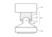
角度調整機構(12)は、第1試料台(13)に固定される球フランジ(26)と、第1ステージ(11)に固定される球座(28)と、球フランジ(26)をかしめることにより球フランジ(26)を球座(28)に固定する固定フランジ(27)とを備えていることが好ましい。 The angle adjustment mechanism (12) includes a ball flange (26) fixed to the first sample stage (13), a ball seat (28) fixed to the first stage (11), and a ball flange (26). It is preferable to provide a fixing flange (27) for fixing the ball flange (26) to the ball seat (28) by crimping.
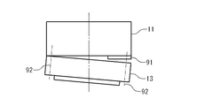
角度調整機構(12)は、複数のシム(91)と、その複数のシム(91)のうちのいくつかのシム(91)を第1ステージ(11)と第1試料台(13)との間に挟んで第1ステージ(11)と第1試料台(13)とを接合する締結部品(92)とを備えていることが好ましい。 The angle adjustment mechanism (12) includes a plurality of shims (91) and some shims (91) of the plurality of shims (91) between the first stage (11) and the first sample stage (13). It is preferable to include a fastening part (92) for joining the first stage (11) and the first sample stage (13) with being interposed therebetween.
角度調整機構(12)は、電気信号により伸び縮みする複数の素子(95)と、複数の素子(95)の各々の一端を第1試料台(13)に接合し、その各々の他端を第1ステージ(11)に接合する締結部品(92)とを備えていることが好ましい。 The angle adjusting mechanism (12) includes a plurality of elements (95) that expand and contract by electrical signals, and one end of each of the plurality of elements (95) joined to the first sample stage (13), and the other end of each of the elements It is preferable that a fastening part (92) joined to the first stage (11) is provided.
角度調整機構(12)は、第1試料台(13)のうちのその第2基板に対向する表面の向きを測定するセンサ(96)と、その測定された表面の向きに基づいて複数の素子(95)を制御する制御装置(97)とをさらに備えている。このとき、制御装置(97)は、その測定された表面が基準面に平行になるように複数の素子(95)を制御する。その基準面としては、キャリッジ支持台(45)のうちの第2試料台に対向する面(54)、第2試料台(46)のうちの第2基板が保持される面、第2基板のうちの第1基板に接合される面が例示される。このとき、常温接合装置(1)(81)は、たとえば、接合チャンバー(2)を大気開放することなしに、第1試料台(13)の向きを補正することができ、好ましい。 The angle adjustment mechanism (12) includes a sensor (96) that measures the orientation of the surface of the first sample stage (13) that faces the second substrate, and a plurality of elements based on the measured orientation of the surface. And a control device (97) for controlling (95). At this time, the control device (97) controls the plurality of elements (95) so that the measured surface is parallel to the reference plane. The reference surface includes a surface (54) of the carriage support table (45) facing the second sample table, a surface of the second sample table (46) on which the second substrate is held, and the second substrate surface. The surface joined to the 1st board | substrate is illustrated. At this time, the room temperature bonding apparatus (1) (81) can correct the direction of the first sample stage (13) without opening the bonding chamber (2) to the atmosphere, which is preferable.
本発明による常温接合装置(1)(81)は、その第2基板を固定するカートリッジ(55)を第2試料台(46)に機械的に固定するメカニカルロック機構をさらに備えている。このとき、常温接合装置(1)(81)は、電磁力を用いないで第2基板を保持することができ、第2基板が電磁力を嫌うときに有効である。 The room temperature bonding apparatus (1) (81) according to the present invention further includes a mechanical lock mechanism for mechanically fixing the cartridge (55) for fixing the second substrate to the second sample stage (46). At this time, the room temperature bonding apparatus (1) (81) can hold the second substrate without using electromagnetic force, and is effective when the second substrate dislikes electromagnetic force.
本発明による常温接合装置(1)(81)は、その第2基板を固定するカートリッジ(106)を第2試料台(46)に磁力を用いて固定するコイル(102)をさらに備えていることが好ましい。 The room-temperature bonding apparatus (1) (81) according to the present invention further includes a coil (102) for fixing the cartridge (106) for fixing the second substrate to the second sample stage (46) using magnetic force. Is preferred.
本発明による常温接合装置(1)(81)は、光を発する光源(71)と、その第1基板またはその第2基板にパターンニングされたアライメントマーク(78,79)を反射するその光の反射光に基づいて画像を撮像するカメラ(73)とをさらに備えている。キャリッジ支持台(45)は、その光とその反射光とが透過する観察窓(74)が形成される。このとき、常温接合装置(1)(81)は、画像に基づいて第2試料台(46)を駆動することにより、第1基板と第2基板とが設計どおりに常温接合されるように、第1基板と第2基板とを位置合わせすることができる。 The room-temperature bonding apparatus (1) (81) according to the present invention includes a light source (71) that emits light and the light that reflects the alignment mark (78, 79) patterned on the first substrate or the second substrate. And a camera (73) that captures an image based on the reflected light. The carriage support (45) has an observation window (74) through which the light and the reflected light are transmitted. At this time, the room temperature bonding apparatus (1) (81) drives the second sample stage (46) based on the image so that the first substrate and the second substrate are bonded at room temperature as designed. The first substrate and the second substrate can be aligned.
本発明による常温接合装置(1)(81)は、第1試料台(13)と第2試料台(46)とを内部に配置する接合チャンバー(2)と、接合チャンバー(2)に形成される排気口(35)を介して接合チャンバー(2)の内部から気体を排気して接合チャンバー(2)の内部に真空雰囲気を生成する真空ポンプ(31)と、その第1基板のうちのその第2基板に対向する第1表面とその第2基板のうちのその第1基板に対向する第2表面とが離れているときに、一箇所から放出される粒子をその真空雰囲気でその第1表面とその第2表面との間に向けて照射する表面清浄化装置(32)とを備えている。その粒子のビームの中心線(36)は、接合チャンバー(2)の内側表面のうちの排気口(35)を除く領域に向いている。このような常温接合装置(1)(81)は、真空ポンプ(31)の汚染が防止されて、長寿命化する。 The room temperature bonding apparatus (1) (81) according to the present invention is formed in a bonding chamber (2) in which a first sample stage (13) and a second sample stage (46) are arranged, and a bonding chamber (2). A vacuum pump (31) for evacuating gas from the inside of the bonding chamber (2) through the exhaust port (35) and generating a vacuum atmosphere in the bonding chamber (2); When the first surface facing the second substrate and the second surface of the second substrate facing the first substrate are separated from each other, the particles emitted from one place are the first in the vacuum atmosphere. A surface cleaning device (32) for irradiating between the surface and the second surface is provided. The center line (36) of the particle beam is directed to a region of the inner surface of the bonding chamber (2) excluding the exhaust port (35). Such a room-temperature bonding apparatus (1) (81) is prevented from being contaminated by the vacuum pump (31) and has a long life.
本発明による常温接合装置(1)(81)は、第1試料台(13)と第2試料台(46)とを内部に配置する接合チャンバー(2)と、ロードロックチャンバー(3)と接合チャンバー(2)との間を開閉するゲートバルブ(5)と、ゲートバルブ(5)を介してその第1基板とその第2基板とをロードロックチャンバー(3)から接合チャンバー(2)に搬送する搬送装置(8)と、その第1表面とその第2表面とが離れているときに、一箇所から放出される粒子をその真空雰囲気でその第1表面とその第2表面との間に向けて照射する表面清浄化装置(32)とを備えている。その粒子のビームの中心線(36)は、接合チャンバー(2)の内側表面のうちのゲートバルブ(5)を除く領域に向いている。このような常温接合装置(1)(81)は、ゲートバルブ(5)の汚染が防止されて、長寿命化する。 The room temperature bonding apparatus (1) (81) according to the present invention includes a bonding chamber (2) in which a first sample stage (13) and a second sample stage (46) are disposed, and a load lock chamber (3). A gate valve (5) that opens and closes between the chamber (2) and the first substrate and the second substrate are transferred from the load lock chamber (3) to the bonding chamber (2) via the gate valve (5). When the conveying device (8) is separated from the first surface and the second surface, particles released from one place are placed between the first surface and the second surface in the vacuum atmosphere. And a surface cleaning device (32) for irradiating it. The center line (36) of the particle beam is directed to the region of the inner surface of the bonding chamber (2) excluding the gate valve (5). Such a room temperature bonding apparatus (1) (81) prevents the gate valve (5) from being contaminated and extends its life.
本発明による常温接合装置(1)(81)は、互いに独立して減圧可能である複数のカセットチャンバー(82−1〜82−4)をさらに備えている。搬送装置(8)は、その第1基板をその複数のカセットチャンバー(82−1〜82−4)のうちの第1カセットチャンバー(82−1〜82−4)から接合チャンバー(2)に搬送し、その第2基板をその複数のカセットチャンバー(82−1〜82−4)のうちの第2カセットチャンバー(82−1〜82−4)から接合チャンバー(2)に搬送し、その第2基板とその第1基板とが常温接合された接合基板を接合チャンバー(2)からその複数のカセットチャンバー(82−1〜82−4)のうちの1つのカセットチャンバー(82−1〜82−4)に搬送する。このような常温接合装置(1)(81)は、タイミングをずらして複数の基板を別々にカセットチャンバー(82−1〜82−4)にセットすることができる。 The room temperature bonding apparatus (1) (81) according to the present invention further includes a plurality of cassette chambers (82-1 to 82-4) that can be decompressed independently of each other. The transfer device (8) transfers the first substrate from the first cassette chamber (82-1 to 82-4) of the plurality of cassette chambers (82-1 to 82-4) to the bonding chamber (2). Then, the second substrate is transferred from the second cassette chamber (82-1 to 82-4) of the plurality of cassette chambers (82-1 to 82-4) to the bonding chamber (2), and the second substrate is transferred to the second chamber. A bonding substrate in which the substrate and the first substrate are bonded at room temperature is joined to one cassette chamber (82-1 to 82-4) of the plurality of cassette chambers (82-1 to 82-4) from the bonding chamber (2). ). Such a room temperature bonding apparatus (1) (81) can set a plurality of substrates separately in the cassette chambers (82-1 to 82-4) at different timings.
本発明による常温接合装置(1)(81)は、その複数のカセットチャンバー(82−1〜82−4)の内部に出し入れ可能に配置される複数カセット(68)をさらに備えている。その複数カセット(68)は、それぞれ、その第2基板またはその第1基板またはその接合基板が配置される複数の棚(69)が形成される。このような常温接合装置(1)(81)は、その2つの基板の複数組をカセット(68)ごとカセットチャンバー(82−1〜82−4)に入れることができ、その接合基板をカセット(68)ごと次工程(ダイシングやエッチング、あるいは、さらに基板を接合接合する工程)に搬送することができる。このような常温接合装置(1)(81)は、タクトタイムを短縮することができ、高効率であり、単位時間あたりの生産量が多く、大量生産に好適である。 The room-temperature bonding apparatus (1) (81) according to the present invention further includes a plurality of cassettes (68) arranged so as to be able to be taken in and out of the plurality of cassette chambers (82-1 to 82-4). The plurality of cassettes (68) are formed with a plurality of shelves (69) on which the second substrate, the first substrate, or the bonding substrate is arranged, respectively. Such a room temperature bonding apparatus (1) (81) can put a plurality of sets of the two substrates into the cassette chamber (82-1 to 82-4) together with the cassette (68). 68) can be transferred to the next step (dicing, etching, or further joining and joining the substrates). Such a room temperature bonding apparatus (1) (81) can reduce the tact time, is highly efficient, has a large production amount per unit time, and is suitable for mass production.
本発明による常温接合装置(1)(81)は、第2試料台(46)に同体に接合される弾性案内(47)をさらに備えている。第2駆動装置(44)は、弾性案内(47)を支持し、弾性案内(47)を駆動することにより、第2試料台(46)を駆動する。弾性案内(47)は、その第1基板とその第2基板とが接触していないときに第2試料台(46)がキャリッジ支持台(45)に接触しないように、かつ、その第1基板とその第2基板とが圧接されるときに第2試料台(46)がキャリッジ支持台(45)に接触するように、弾性変形することが好ましい。 The room temperature bonding apparatus (1) (81) according to the present invention further includes an elastic guide (47) bonded to the second sample stage (46) in the same body. The second drive device (44) supports the elastic guide (47) and drives the second sample stage (46) by driving the elastic guide (47). The elastic guide (47) prevents the second sample base (46) from contacting the carriage support (45) when the first substrate and the second substrate are not in contact with each other, and the first substrate. It is preferable that the second sample table (46) is elastically deformed so that the second sample table (46) contacts the carriage support table (45) when the second substrate and the second substrate are pressed against each other.
第2試料台(46)は、第2試料台(46)がキャリッジ支持台(45)に摺動してその第2方向に移動することが好ましい。 The second sample stage (46) is preferably moved in the second direction by sliding the second sample stage (46) on the carriage support (45).
本発明による常温接合装置(1)(81)は、第1基板を保持する第1試料台(13)を支持する第1ステージ(11)を第1方向に駆動する第1駆動装置(14)と、第2基板を保持する第2試料台(46)をその第1方向に平行でない第2方向に駆動する第2駆動装置(44)と、その第2基板とその第1基板とが圧接されるときに、その第1方向に第2試料台(46)を支持するキャリッジ支持台(45)と、その第2基板を固定するカートリッジ(55)を第2試料台(46)に機械的に固定するメカニカルロック機構とを備えている。このとき、常温接合装置(1)(81)は、第1基板と第2基板とを圧接するときに、第2駆動装置(44)に加わる荷重を低減することができ、第2駆動装置(44)の耐荷重を越えたより大きな荷重を第1基板と第2基板とに加えることができる。常温接合装置(1)(81)は、さらに、第2基板に電磁力を印加することなしに、第2基板を着脱可能に第2試料台(46)に支持することができる。このため、常温接合装置(1)(81)は、電磁力を印加することができない基板にその大きな荷重を負荷することができる。 A room-temperature bonding apparatus (1) (81) according to the present invention includes a first driving device (14) for driving a first stage (11) supporting a first sample stage (13) holding a first substrate in a first direction. A second driving device (44) for driving the second sample stage (46) holding the second substrate in a second direction not parallel to the first direction, and the second substrate and the first substrate are in pressure contact with each other. When this is done, a carriage support base (45) for supporting the second sample base (46) in the first direction and a cartridge (55) for fixing the second substrate are mechanically attached to the second sample base (46). And a mechanical lock mechanism to be fixed to. At this time, the room temperature bonding apparatus (1) (81) can reduce the load applied to the second driving device (44) when the first substrate and the second substrate are pressed against each other, and the second driving device ( A larger load exceeding the load capacity of 44) can be applied to the first substrate and the second substrate. The room-temperature bonding apparatus (1) (81) can further support the second substrate detachably on the second sample stage (46) without applying electromagnetic force to the second substrate. For this reason, room temperature bonding apparatus (1) (81) can load the big load to the board | substrate which cannot apply an electromagnetic force.
本発明による常温接合装置(1)(81)は、第1試料台(13)と第2試料台(46)とを内部に配置する接合チャンバー(2)と、接合チャンバー(2)に形成される排気口(35)を介して接合チャンバー(2)の内部から気体を排気して接合チャンバー(2)の内部に真空雰囲気を生成する真空ポンプ(31)と、ロードロックチャンバー(3)と接合チャンバー(2)との間を開閉するゲートバルブ(5)と、ゲートバルブ(5)を介してその第1基板とその第2基板とをロードロックチャンバー(3)から接合チャンバー(2)に搬送する搬送装置(8)と、その第1基板のうちのその第2基板に対向する第1表面とその第2基板のうちのその第1基板に対向する第2表面とが離れているときに、一箇所から放出される粒子をその真空雰囲気でその第1表面とその第2表面との間に向けて照射する表面清浄化装置(32)とを備えている。その粒子のビームの中心線は、接合チャンバー(2)の内側表面のうちの排気口(35)とゲートバルブ(5)とを除く領域に向いている。 The room temperature bonding apparatus (1) (81) according to the present invention is formed in a bonding chamber (2) in which a first sample stage (13) and a second sample stage (46) are arranged, and a bonding chamber (2). A vacuum pump (31) for evacuating gas from the inside of the joining chamber (2) through the exhaust port (35) and generating a vacuum atmosphere inside the joining chamber (2); and joining the load lock chamber (3) A gate valve (5) that opens and closes between the chamber (2) and the first substrate and the second substrate are transferred from the load lock chamber (3) to the bonding chamber (2) via the gate valve (5). And when the first surface of the first substrate facing the second substrate and the second surface of the second substrate facing the first substrate are separated from each other. The particles emitted from one location It includes surface cleaning apparatus for irradiating during its first surface and its second surface in a vacuum atmosphere and (32). The center line of the particle beam is directed to a region of the inner surface of the bonding chamber (2) excluding the exhaust port (35) and the gate valve (5).
本発明による常温接合装置(1)(81)は、第1基板を保持する第1試料台(13)を支持する第1ステージ(11)を第1方向に駆動する第1駆動装置(14)と、第2基板を保持する第2試料台(46)をその第1方向に平行でない第2方向に駆動する第2駆動装置(44)と、その第2基板とその第1基板とが圧接されるときに、その第1方向に第2試料台(46)を支持するキャリッジ支持台(45)と、光を発する光源(71)と、その第1基板またはその第2基板にパターンニングされたアライメントマーク(78,79)を反射するその光の反射光に基づいて画像を撮像するカメラ(73)とを備えている。キャリッジ支持台(45)は、その光とその反射光とが透過する観察窓(74)が形成される。このとき、常温接合装置(1)(81)は、第1基板と第2基板とを圧接するときに、第2駆動装置(44)に加わる荷重を低減することができ、第2駆動装置(44)の耐荷重を越えたより大きな荷重を第1基板と第2基板とに加えることができる。常温接合装置(1)(81)は、さらに、その画像に基づいて第2試料台(46)を駆動することにより、第1基板と第2基板とが設計どおりに常温接合されるように、第1基板と第2基板とを位置合わせすることができる。 A room-temperature bonding apparatus (1) (81) according to the present invention includes a first driving device (14) for driving a first stage (11) supporting a first sample stage (13) holding a first substrate in a first direction. A second driving device (44) for driving the second sample stage (46) holding the second substrate in a second direction not parallel to the first direction, and the second substrate and the first substrate are in pressure contact with each other. Patterning on the first substrate or the second substrate, the carriage support table (45) that supports the second sample table (46) in the first direction, the light source (71) that emits light, and the first substrate. And a camera (73) that captures an image based on the reflected light of the light that reflects the alignment mark (78, 79). The carriage support (45) has an observation window (74) through which the light and the reflected light are transmitted. At this time, the room temperature bonding apparatus (1) (81) can reduce the load applied to the second driving device (44) when the first substrate and the second substrate are pressed against each other, and the second driving device ( A larger load exceeding the load capacity of 44) can be applied to the first substrate and the second substrate. The room temperature bonding apparatus (1) (81) further drives the second sample stage (46) based on the image so that the first substrate and the second substrate are bonded at room temperature as designed. The first substrate and the second substrate can be aligned.
本発明による常温接合装置(1)(81)は、第1試料台(13)と第2試料台(46)とを内部に配置する接合チャンバー(2)と、接合チャンバー(2)に形成される排気口(35)を介して接合チャンバー(2)の内部から気体を排気して接合チャンバー(2)の内部に真空雰囲気を生成する真空ポンプ(31)と、ロードロックチャンバー(3)と接合チャンバー(2)との間を開閉するゲートバルブ(5)と、ゲートバルブ(5)を介してその第1基板とその第2基板とをロードロックチャンバー(3)から接合チャンバー(2)に搬送する搬送装置(8)と、その第1基板のうちのその第2基板に対向する第1表面とその第2基板のうちのその第1基板に対向する第2表面とが離れているときに、一箇所から放出される粒子をその真空雰囲気でその第1表面とその第2表面との間に向けて照射する表面清浄化装置(32)とを備えている。その粒子のビームの中心線は、接合チャンバー(2)の内側表面のうちの排気口(35)とゲートバルブ(5)とを除く領域に向いている。このとき、常温接合装置(1)(81)は、第1基板と第2基板とを圧接するときに、第2駆動装置(44)に加わる荷重を低減することができ、第2駆動装置(44)の耐荷重を越えたより大きな荷重を第1基板と第2基板とに加えることができる。このような常温接合装置(1)(81)は、さらに、真空ポンプ(31)の汚染とゲートバルブ(5)の汚染が防止されて、長寿命化する。 The room temperature bonding apparatus (1) (81) according to the present invention is formed in a bonding chamber (2) in which a first sample stage (13) and a second sample stage (46) are arranged, and a bonding chamber (2). A vacuum pump (31) for evacuating gas from the inside of the joining chamber (2) through the exhaust port (35) and generating a vacuum atmosphere inside the joining chamber (2); and joining the load lock chamber (3) A gate valve (5) that opens and closes between the chamber (2) and the first substrate and the second substrate are transferred from the load lock chamber (3) to the bonding chamber (2) via the gate valve (5). And when the first surface of the first substrate facing the second substrate and the second surface of the second substrate facing the first substrate are separated from each other. The particles emitted from one location It includes surface cleaning apparatus for irradiating during its first surface and its second surface in a vacuum atmosphere and (32). The center line of the particle beam is directed to a region of the inner surface of the bonding chamber (2) excluding the exhaust port (35) and the gate valve (5). At this time, the room temperature bonding apparatus (1) (81) can reduce the load applied to the second driving device (44) when the first substrate and the second substrate are pressed against each other, and the second driving device ( A larger load exceeding the load capacity of 44) can be applied to the first substrate and the second substrate. Such a room temperature bonding apparatus (1) (81) further prevents the contamination of the vacuum pump (31) and the gate valve (5), thereby extending the life.
本発明による常温接合装置は、第1基板と第2基板とを圧接するときに、第2駆動装置に加わる荷重を低減することができ、第2駆動装置の耐荷重を越えたより大きな荷重を第1基板と第2基板とに加えることができる。本発明による常温接合装置は、さらに、第1基板と第2基板との接合面に、より大きな荷重をより均一に負荷することができる。 The room temperature bonding apparatus according to the present invention can reduce the load applied to the second driving device when the first substrate and the second substrate are pressed together, and can apply a larger load exceeding the load resistance of the second driving device. It can be added to the first substrate and the second substrate. The room temperature bonding apparatus according to the present invention can further apply a larger load more uniformly to the bonding surface between the first substrate and the second substrate.
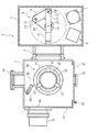
図面を参照して、本発明による常温接合装置の実施の形態を記載する。その常温接合装置1は、図1に示されているように、接合チャンバー2とロードロックチャンバー3とを備えている。接合チャンバー2とロードロックチャンバー3は、内部を環境から密閉する容器に形成されている。常温接合装置1は、さらに、ゲートバルブ5を備えている。ゲートバルブ5は、接合チャンバー2とロードロックチャンバー3との間に介設され、接合チャンバー2の内部とロードロックチャンバー3の内部とを接続するゲートを閉鎖し、または、開放する。
An embodiment of a room temperature bonding apparatus according to the present invention will be described with reference to the drawings. The room-
ロードロックチャンバー3は、第1カセット台6と第2カセット台7と搬送装置8とを内部に備えている。第1カセット台6と第2カセット台7とは、基板を載せるために利用されるカセットが配置される。なお、ロードロックチャンバー3は、このようなカセット台を3個以上設置されても構わない。
The
ロードロックチャンバー3は、さらに、図示されていない真空ポンプと蓋とを備えている。その真空ポンプは、ロードロックチャンバー3の内部から気体を排気する。その真空ポンプとしては、内部の金属製の複数の羽根が気体分子を弾き飛ばすことにより排気するターボ分子ポンプが例示される。その蓋は、ロードロックチャンバー3の外部と内部とを接続するゲートを閉鎖し、または、開放する。そのゲートの大きさは、第1カセット台6と第2カセット台7とに配置されるカセットより大きい。
The
搬送装置8は、第1アーム15と第2アーム16と第3アーム17と第1節18と第2節19と第3節20とを備えている。第1アーム15と第2アーム16と第3アーム17とは、それぞれ、棒状に形成されている。第1節18は、ロードロックチャンバー3の床板に支持され、回転軸22を中心に回転可能に第1アーム15を支持している。回転軸22は、鉛直方向に平行である。第2節19は、第1節18に支持され、回転軸23を中心に回転可能に第2アーム16を支持している。回転軸23は、鉛直方向に平行であり、すなわち、回転軸22に平行である。第3節20は、第2節19に支持され、回転軸24を中心に回転可能に第3アーム17を支持している。回転軸24は、鉛直方向に平行であり、すなわち、回転軸23に平行である。第3アーム17は、第3節20に接合される端と反対側の端に、爪21を備えている。爪21は、第1カセット台6または第2カセット台に配置されるカセットに載せられる基板を把持するために利用される。
The
搬送装置8は、さらに、図示されていない昇降機構と伸縮機構とを備えている。その昇降機構は、ユーザの操作により、第1アーム15を昇降させて、爪21により把持される基板を昇降させる。その伸縮機構は、第1節18と第2節19と第3節20とを制御して第3アーム17の長手方向に平行に第3アーム17を平行移動させる。
The
搬送装置8は、その基板をロードロックチャンバー3から接合チャンバー2にゲートバルブ5を介して搬送し、その基板を接合チャンバー2からロードロックチャンバー3にゲートバルブ5を介して搬送する。
The
接合チャンバー2は、真空ポンプ31とイオンガン32と電子銃33とを備えている。接合チャンバー2は、容器を形成する壁34の一部分に排気口35が形成されている。真空ポンプ31は、接合チャンバー2の外部に配置され、排気口35を介して接合チャンバー2の内部から気体を排気する。真空ポンプ31としては、内部の金属製の複数の羽根が気体分子を弾き飛ばすことにより排気するターボ分子ポンプが例示される。イオンガン32は、1つの照射方向36に向けられて配置され、照射方向36に向けて加速された荷電粒子を放出する。その荷電粒子としては、アルゴンイオンが例示される。イオンガン32は、その基板の表面を清浄化する他の表面清浄化装置に置換することができる。その表面清浄化装置としては、プラズマガン、高速原子ビーム源などが例示される。電子銃33は、イオンガン32により荷電粒子が照射される対象に向けられて配置され、その対象に向けて加速された電子を放出する。
The
壁34は、一部分に扉37が形成されている。扉37は、ヒンジ38を備えている。ヒンジ38は、壁34に対して回転可能に扉37を支持している。壁34は、さらに、一部分に窓39が形成されている。窓39は、気体を透過しないで可視光を透過する材料から形成されている。窓39は、ユーザがイオンガン32により荷電粒子が照射される対象または、接合状態を接合チャンバー2の外部から見えるように配置されていれば壁34のどこでもかまわない。
The
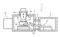
接合チャンバー2は、図2に示されているように、さらに、上側基板支持部41と下側基板支持部42とを内部に備えている。上側基板支持部41は、上側ステージ11と角度調整機構12と上側試料台13と上側ステージ駆動装置14とを備えている。上側ステージ11は、接合チャンバー2に対して鉛直方向に平行移動可能に支持されている。角度調整機構12は、向きを変更可能に、上側試料台13を上側ステージ11に支持している。上側試料台13は、その下端に誘電層を備え、その誘電層と基板の間に電圧を印加し、静電力によってその基板をその誘電層に吸着する。上側ステージ駆動装置14は、ユーザの操作により、上側ステージ11を接合チャンバー2に対して鉛直方向に平行移動させる。下側基板支持部42は、基板を上端に支持する。
As shown in FIG. 2, the
イオンガン32は、上側基板支持部41に支持される基板と下側基板支持部42に支持されるその基板とが離れているときに、上側基板支持部41に支持される基板と下側基板支持部42に支持される基板との間の空間に向けられ、接合チャンバー2の壁34の一部の内側表面に向けられている。すなわち、イオンガン32の照射方向36は、上側基板支持部41に支持される基板と下側基板支持部42に支持される基板との間を通り、接合チャンバー2の壁34の一部の内側表面に交差する。
The
図3は、角度調整機構12を示している。角度調整機構12は、球フランジ26と固定フランジ27と球座28とを備えている。球フランジ26は、支持部分とフランジ部分とから形成されている。その支持部分は、上側試料台13に接合されている。そのフランジ部分は、点29を中心とする球に形成されている。固定フランジ27は、かしめ固定により、球フランジ26のフランジ部分に接合されている。球座28は、球フランジ26のフランジ部分に密着する球座面が形成されている。球座28は、さらに、上側ステージ11に接合され、その球座面が球フランジ26のフランジ部分に密着するように、ボルトに例示される締結具により固定フランジ27に接合されている。
FIG. 3 shows the
図4は、固定フランジ27を示している。固定フランジ27は、分割リング29−1〜29−2を備えている。分割リング29−1〜29−2は、それぞれ、リングの一部に形成されている。分割リング29−1〜29−2は、そのリングの内側が球フランジ26のフランジ部分に接触するように配置され、図示されていないボルトにより締結されることにより、球フランジ26のフランジ部分に接合される。
FIG. 4 shows the fixing
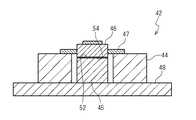
図5は、下側基板支持部42を詳細に示している。下側基板支持部42は、位置決めステージ44とキャリッジ支持台45と下側試料台46と弾性案内47とを備えている。位置決めステージ44は、接合チャンバー2の底板48に支持されている。キャリッジ支持台45は、例えば、円柱状に形成され、接合チャンバー2の底板48に支持されている。キャリッジ支持台45は、その円柱の上端に滑らかな支持面52を有している。支持面52は、鉛直方向に垂直である。
FIG. 5 shows the
下側試料台46は、例えば、円柱状に形成される。下側試料台46は、その円柱の下端に滑らかな支持面54を有している。下側試料台46の支持面54の反対側の面は、支持面54と平行になるように、高精度(たとえば、平行度が10μm以内)に加工されている。弾性案内47は、弾性体から形成され、下側試料台46の側面に同体に接合されている。位置決めステージ44は、下側試料台46の支持面54がキャリッジ支持台45の支持面52に接触しないように、弾性案内47を水平方向に平行移動可能に支持している。このとき、支持面54と支持面52とは、100μm程度離れている。弾性案内47は、さらに、上側基板支持部41により下側試料台46が鉛直下方向に押されたときに、下側試料台46の支持面54がキャリッジ支持台45の支持面52に接触するように弾性変形する。位置決めステージ44は、さらに、ユーザの操作により弾性案内47を水平方向に平行な方向に平行移動させ、弾性案内47を鉛直方向に平行な回転軸を中心に回転移動させる。
The
このような下側基板支持部42は、下側試料台46が上側基板支持部41により鉛直下方向に押されたときに、押付け荷重が下側試料台46を支持する弾性案内に加わることで、キャリッジ支持台45が下側試料台46を支持する。このため、常温接合装置1は、位置決めステージ44に大きな荷重をかけずに上側基板支持部41にセットされた基板と下側基板支持部42にセットされた基板とに、位置決めステージ44の耐荷重を越えるより大きな荷重を加えることができる。
The lower
なお、下側基板支持部42は、位置決めステージ44と弾性案内47とを他の位置決め機構に置換することもできる。このとき、キャリッジ支持台45は、支持面52が下側試料台46の支持面54に接触して下側試料台46を支持する。その位置決め機構は、ユーザの操作により下側試料台46を水平方向に平行な方向に平行移動させ、下側試料台46を鉛直方向に平行な回転軸を中心に回転移動させる。このとき、下側試料台46は、キャリッジ支持台45の支持面52に摺動して移動する。
The lower
図6は、下側試料台46に保持される基板を示している。その基板43は、カートリッジ55に接合されている。
FIG. 6 shows the substrate held on the
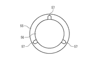
図7は、カートリッジ55を示している。カートリッジ55は、概ね円盤状に形成され、接着面56と複数の穴57とが形成されている。接着面57は、平坦に形成されている。基板43は、図示されていないウェハテープを用いてカートリッジ55の接着面57に固定されている。複数の穴57は、接着面57の外側に形成されている。
FIG. 7 shows the
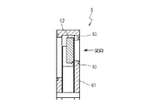
図8は、下側試料台46を示している。下側試料台46は、メカニカルロック機構によりカートリッジ55を保持することにより、基板43を保持する。下側試料台46は、概ね円盤状に形成され、複数のピン58とカム59とを備えている。複数のピン58は、それぞれ、棒状に形成され、下側試料台46の円盤の半径方向に平行移動可能に下側試料台46に支持されている。カム59は、下側試料台46の円盤の中央に配置され、図示されていない回転機構(たとえば、モータ)により回転されることにより複数のピン58を外側に向かって駆動する。すなわち、下側試料台46は、複数のピン58がカートリッジ55の複数の穴57に入るように基板43が配置され、ユーザの操作によりカム59が回転させられることにより、基板43を固定する。
FIG. 8 shows the
上側試料台13に保持される基板は、基板43と同様にして、カートリッジ55に接合されている。さらに、上側試料台13は、下側試料台46と同様にして構成されている。すなわち、上側試料台13は、概ね円盤状に形成され、複数のピンとカムとを備えている。その複数のピンは、それぞれ、棒状に形成され、上側試料台13の円盤の半径方向に平行移動可能に上側試料台13に支持されている。そのカムは、上側試料台13の円盤の中央に配置され、回転することによりその複数のピンを外側に向かって駆動する。すなわち、上側試料台13は、その複数のピンがカートリッジ55の複数の穴57に入るように基板43が配置され、ユーザの操作によりそのカムが回転させられることにより、基板43を固定する。
The substrate held on the
このようなメカニカルロック機構を備えた試料台は、電磁力を用いないで基板43を保持することができ、電磁力が加わることが嫌われる基板43を保持することに有効である。
The sample stage provided with such a mechanical lock mechanism can hold the
常温接合装置1は、図9に示されているように、さらに、アライメント装置70を備えている。アライメント装置70は、赤外照明71とレンズ72とカメラ73とを備えている。このとき、キャリッジ支持台45は、透明部位74が形成されている。透明部位74は、赤外照明71が照射する赤外線に対して透明な材料で形成されている。さらに、下側試料台46は、透明部位75が形成されている。透明部位75は、赤外照明71が照射する赤外線に対して透明な材料で形成され、下側試料台46のうちの透明部位74の近傍に配置されている。さらに、その基板がカートリッジ55に接合されているときに、カートリッジ55は、同様にして、透明部位が形成されている。その透明部位は、赤外照明71が照射する赤外線に対して透明な材料で形成され、下側試料台46のうちの透明部位75の近傍に配置される。
As shown in FIG. 9, the room
赤外照明71とレンズ72とカメラ73とは、接合チャンバー2に固定されている。赤外照明71は、半導体を透過する赤外線を生成する。その赤外線の波長としては、1μm以上の波長が例示される。レンズ72は、赤外照明71により生成される赤外線の向きを鉛直方向に変えて、透明部位74、75を介して、上側基板支持部41により保持される基板76にその赤外線を照射し、または、下側基板支持部42により保持される基板77にその赤外線を照射する。レンズ72は、さらに、基板76を反射する赤外線の反射光をカメラ73に透過し、基板77を反射する赤外線の反射光をカメラ73に透過する。カメラ73は、レンズ72を透過した反射光に基づいて基板76の一部の画像を生成し、基板77の一部の画像を生成する。
The
基板76は、基板77に対向する表面の一部にアライメントマーク78が形成されている。基板77は、基板76に対向する表面にアライメントマーク79が形成されている。基板77は、アライメントマーク79が基板77のうちの透明部位74、75に配置されるように、下側試料台46に支持される。アライメントマーク78とアライメントマーク79とは、基板76と基板77とが設計どおりに常温接合されるときに、ちょうど向かい合って配置されるように、設計されている。アライメントマーク78は、基板76の複数の箇所に形成され、アライメントマーク79は、基板77の複数の箇所に形成されている。
The
このとき、カートリッジ55と下側試料台46とキャリッジ支持台45とは、アライメント装置70により基板77のアライメントマーク79が撮影されるように、形成されている。すなわち、カートリッジ55は、基板77に接合されたときに、その複数のアライメントマーク79が配置される複数の箇所に複数の透明部位がそれぞれ形成されている。下側試料台46は、下側基板支持部42が基板77を保持したときに、その複数のアライメントマーク79が配置される複数の箇所に複数の透明部位75がそれぞれ形成されている。キャリッジ支持台45は、下側基板支持部42が基板77を保持したときに、その複数のアライメントマーク79が配置される複数の箇所に複数の透明部位74がそれぞれ形成されている。
At this time, the
図10は、ゲートバルブ5を示している。ゲートバルブ5は、ゲート61と扉62とを備えている。ゲート61は、接合チャンバー2の内部とロードロックチャンバー3の内部とを接続する開口部を形成し、その開口部の周辺に封止面63を有している。扉62は、ユーザの操作に基づいて図示されていない機構により移動されて、封止面63に密着してゲート61の開口部を閉鎖し、ゲート61の開口部から離れてゲート61の開口部を開放する。
FIG. 10 shows the
常温接合装置1は、イオンガン32から放出される粒子に強く曝されないように、かつ、イオンガン32から放出される粒子により壁34の表面や内蔵物の表面、その基板の表面から弾き飛ばされた粒子に強く曝されないように、ゲートバルブ5と真空ポンプ31とが配置されるように製造される。
The room-
ゲートバルブ5は、イオンガン32から放出される粒子に強く曝され、または、イオンガン32から放出される粒子によりその基板の表面から弾き飛ばされた粒子に強く曝されると、封止面63周辺にその粒子による汚染膜ができる。その汚染膜が、ゲートバルブ5の開閉により剥れ、汚染物が封止面63に入り込み、接合チャンバー2の内部とロードロックチャンバー3の内部とを密閉することができなくなる。このような常温接合装置1は、ゲートバルブ5の封止面63の汚染を防止して、長寿命化することができる。
When the
真空ポンプ31は、排気口35がイオンガン32から放出される粒子に強く曝され、または、イオンガン32から放出される粒子により壁34の表面や内蔵物の表面、その基板の表面から弾き飛ばされた粒子に強く曝されると、内部の金属製の複数の羽根が損傷、または羽根に汚染膜ができる。その羽根の損傷・汚染膜の固化堆積により、真空ポンプ31の排気性能の低下を引き起こす可能性がある。また、汚染膜が剥れると真空ポンプ31がそれを吸い込んでしまい、真空ポンプ31を壊す可能性がある。このような常温接合装置1は、真空ポンプ31の羽根の損傷、汚染を防止して、長寿命化することができる。
In the
図11は、搬送装置8の爪21を示している。爪21は、支持面64、65と非支持面66とが形成されている。支持面64、65は、同一の水平面に沿うように形成され、鉛直方向上向きに向けられている。非支持面66は、支持面64、65が沿う水平面より鉛直下側に配置される他の水平面に沿うように形成され、支持面64と支持面65との間に配置されている。爪21は、図12に示されているように、基板67が支持面64、65に接触し、基板67が非支持面66に接触しないように、基板67を把持する。このとき、爪21は、基板67の常温接合装置1により常温接合される接合面が上を向いているときでも下を向いているときでも、その接合面が搬送装置8に接触しないで、その接合面が汚染されることによる接合不良の発生を防止することができる。
FIG. 11 shows the
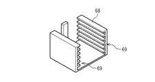
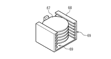
図13は、第1カセット台6または第2カセット台7に配置されるカセットを示している。そのカセット68は、対向する壁面に水平である複数(たとえば、25)の棚69がそれぞれ鉛直方向に1列に並んで配置されている。カセット68は、図14に示されているように、基板67が棚69に接触し、基板67の接合面がカセット68に接触しないように、基板67を配置する。このとき、カセット68は、基板67の常温接合装置1により常温接合される接合面が上を向いているときでも下を向いているときでも、その接合面がカセット68に接触しないで、その接合面が汚染されることによる接合不良の発生を防止することができる。
FIG. 13 shows cassettes arranged on the first cassette base 6 or the second cassette base 7. In the
常温接合装置1を用いて常温接合するときの動作は、上側試料台の向きを補正する動作と常温接合する動作とを備えている。
The operation when performing room temperature bonding using the room
上側試料台の向きを補正する動作は、下側基板支持部42が下側試料台46と弾性案内47とを備えていない状態から実行される。作業者は、まず、上側試料台13の向きを測定する。作業者は、上側試料台13の基板が配置される面がキャリッジ支持台45の支持面52に平行でないときに、角度調整機構12を用いて、上側試料台13の基板が配置される面と支持面52とが平行になるように調整する。すなわち、作業者は、上側試料台13の基板が配置される面と支持面52とが平行になるように、球フランジ26を固定フランジ27によりかしめ固定し、固定フランジ27を球座28に固定する。
The operation of correcting the orientation of the upper sample stage is executed from a state where the lower
作業者は、このような角度調整を実施後に、下側基板支持部42に下側試料台46と弾性案内47とを取り付ける。作業者は、次いで、下側試料台46の支持面54がキャリッジ支持台45の支持面52に接触するように、上側基板支持部41を下側基板支持部42に押し付ける。このとき、作業者は、上側試料台13の基板が配置される面と下側試料台46の基板が配置される面とに印加される荷重の分布を計測し、その荷重分布が均一であることを確認する。
After performing such angle adjustment, the operator attaches the
なお、上側試料台の向きを補正する動作は、下側試料台46がキャリッジ支持台45の支持面52に接触して支持されているときに、他の動作に置換される。その動作では、作業者は、まず、上側試料台13の向きを測定する。作業者は、上側試料台13の基板が配置される面と下側試料台46の基板が配置される面とが平行でないときに、角度調整機構12を用いて、上側試料台13の基板が配置される面と下側試料台46の基板が配置される面とが平行になるように調整する。ここで、下側試料台46が基板を保持しているときに、上側試料台13の基板が配置される面が下側試料台46に保持されている基板の上側試料台13に対向する面に平行になるように、調整することもできる。すなわち、作業者は、上側試料台13の基板が配置される面と下側試料台46の基板が配置される面とが平行になるように、球フランジ26を固定フランジ27によりかしめ固定し、固定フランジ27を球座28に固定する。作業者は、次いで、上側基板支持部41を下側基板支持部42に押し付ける。このとき、作業者は、上側試料台13の基板が配置される面と下側試料台46の基板が配置される面とに印加される荷重の分布を計測し、その荷重分布が均一であることを確認する。
The operation of correcting the orientation of the upper sample stage is replaced with another operation when the
なお、上側試料台13が基板を保持しているときには、上側試料台13の向きに置換して、その基板の下側試料台46に対向する面の向きを測定することもできる。
When the
このような上側試料台の向きを補正する動作によれば、上側試料台13の基板が下側試料台46の基板に常温接合されるときに、上側試料台13の基板と下側試料台46の基板との接合面に荷重がより均一に負荷されることができる。この結果、このような動作は、その常温接合により接合基板に複数のデバイスが形成されるときに、その複数のデバイスの歩留まりを向上させ、常温接合装置1による常温接合の信頼性を向上させ、常温接合装置1をより実用的にすることができる。このような動作によれば、さらに、キャリッジ支持台45の支持面52と下側試料台46の基板が配置される面とが平行になるように調整する必要がなく、その荷重分布をより容易に均一にすることができる。このとき、常温接合装置1は、キャリッジ支持台45の支持面52と下側試料台46の基板が配置される面とが平行になるように調整する機構を備える必要がなく、より容易に製造されることができる。
According to such an operation for correcting the orientation of the upper sample stage, when the substrate of the
図15は、その常温接合する動作を示している。作業者は、上側試料台の向きを補正する動作が実行された後に、まず、ゲートバルブ5を閉鎖して(ステップS1)、真空ポンプ31を用いて接合チャンバー2の内部に真空雰囲気を生成し、ロードロックチャンバー3の内部に大気圧雰囲気を生成する。
FIG. 15 shows the operation for bonding at room temperature. After the operation of correcting the orientation of the upper sample stage is performed, the operator first closes the gate valve 5 (step S1) and generates a vacuum atmosphere inside the
作業者は、複数の基板をカセット68に装填する。その複数の基板は、接合面が下向きになるようにカセット68に装填される。作業者は、さらに、その複数の基板にそれぞれ常温接合される他の複数の基板を他のカセット68に装填する。その複数の基板は、接合面が上向きになるようにカセット68に装填される。作業者は、ロードロックチャンバー3の蓋を開けて、接合面が下向きの基板が装填されたカセット68を第1カセット台6に配置し、接合面が上向きの基板が装填されたカセット68を第2カセット台7に配置する(ステップS2)。カセット台が3個以上ある場合は、それらも配置する。作業者は、ロードロックチャンバー3の蓋を閉めて、ロードロックチャンバー3の内部に真空雰囲気を生成し、ゲートバルブ5を開放する(ステップS3)。
The operator loads a plurality of substrates into the
作業者は、搬送装置8を用いて、第1カセット台6に配置されたカセット68に装填された基板の1つを上側基板支持部41にセットし、第2カセット台7に配置されたカセット68に装填された基板の1つを下側基板支持部42にセットする(ステップS4)。作業者は、ゲートバルブ5を閉鎖する(ステップS5)。
The operator uses the
作業者は、ゲートバルブ5を閉鎖した後に、上側基板支持部41にセットされた基板と下側基板支持部42にセットされた基板とを常温接合する。すなわち、作業者は、上側基板支持部41にセットされた基板と下側基板支持部42にセットされた基板とが離れた状態で、上側基板支持部41にセットされた基板と下側基板支持部42にセットされた基板との間にイオンガン32を用いて粒子を放出する。その粒子は、その基板に照射され、その基板の表面に形成される酸化物等を除去し、その基板の表面に付着している不純物を除去する。作業者は、上側基板支持部41の上側ステージ駆動装置14を操作して、上側試料台13を鉛直下方向に下降させて、上側基板支持部41にセットされた基板と下側基板支持部42にセットされた基板とを近づける。作業者は、アライメント装置70を用いて上側基板支持部41にセットされた基板のアライメントマークと下側基板支持部42にセットされた基板のアライメントマークとを画像に撮像する。作業者は、その画像に基づいて下側基板支持部42の位置決め機構を操作して、上側基板支持部41にセットされた基板と下側基板支持部42にセットされた基板とが設計通りに接合されるように、下側基板支持部42にセットされた基板の位置を移動する。作業者は、上側基板支持部41の上側ステージ駆動装置14を操作して、上側試料台13を鉛直下方向に下降させて、上側基板支持部41にセットされた基板を下側基板支持部42にセットされた基板に接触させる。このとき、下側基板支持部42の弾性案内47は弾性変形し、下側基板支持部42の下側試料台46はキャリッジ支持台45に接触してキャリッジ支持台45に支持される。上側基板支持部41にセットされた基板と下側基板支持部42にセットされた基板とは、その接触により接合され、1枚の接合基板が生成される。
The operator closes the
このような常温接合によれば、上側試料台13の向きを補正する動作が実行された後に実行されることにより、上側基板支持部41にセットされた基板と下側基板支持部42にセットされた基板との接合面に荷重をより均一に負荷することができ、常温接合の歩留まりを向上させることができる。このような常温接合によれば、さらに、下側試料台46がキャリッジ支持台45に接触して支持されことにより、位置決めステージ44に耐荷重を越える大きな荷重が印加されることを防止しつつ、上側基板支持部41にセットされた基板と下側基板支持部42にセットされた基板との接合面に、より大きな荷重をより均一に負荷することができる。
According to such room temperature bonding, it is performed after the operation of correcting the orientation of the
作業者は、上側試料台13を鉛直上方向に上昇させて、ゲートバルブ5を開放する(ステップS7)。作業者は、搬送装置8を用いて、第1カセット台6に配置されたカセット68のうちの空いている棚に、下側基板支持部42にセットされている接合基板を搬送する(ステップS8)。カセット台が3個以上ある場合は、ステップS4〜ステップS8の動作は、装填された基板がすべて常温接合されるまで(ステップS9、YES)繰り返し実行される。
The operator raises the
作業者は、装填された基板がすべて常温接合されると(ステップS9、YES)、ゲートバルブ5を閉鎖して(ステップS10)、ロードロックチャンバー3の内部に大気を供給してロードロックチャンバー3の内部に大気圧雰囲気を生成する。作業者は、ロードロックチャンバー3の蓋を開けて、第1カセット台6、第2カセット台7から接合基板をカセット68ごと取り出す(ステップS11)。
When all the loaded substrates are bonded at room temperature (step S9, YES), the operator closes the gate valve 5 (step S10), supplies the atmosphere to the inside of the
このような動作によれば、その接合された全部の基板をカセット68ごと次工程に搬送することができる。このような常温接合方法は、その接合された全部の基板を別のカセットに再装填する作業が介在しないために、タクトタイムを短縮することができ、高効率であり、単位時間あたりの生産量が多く、大量生産に好適である。
According to such an operation, all the bonded substrates can be transported together with the
さらに、ステップS2の接合面が下向きの基板が装填されたカセット68を第1カセット台6に配置し、接合面が上向きの基板が装填されたカセット68を第2カセット台7に配置することによれば、搬送装置2は、接合チャンバー2またはロードロックチャンバー3の内部で基板を裏返す必要がない。このため、接合チャンバー2とロードロックチャンバー3とは、基板を裏返すための空間を内部に設ける必要がなく、よりコンパクトに形成されることができる。さらに、搬送装置8は、基板を裏返すための機構を備える必要がなく、より容易に製造されることができる。その結果、常温接合装置1は、よりコンパクトに、より低コストに製造されることができる。
Further, the
本発明による常温接合装置の実施の他の形態は、既述の実施の形態における常温接合装置1のロードロックチャンバー3が第1カセット台6と第2カセット台7とを内部に備えないで、代わりに複数のカセットチャンバーを備えている。すなわち、その常温接合装置81は、図16に示されているように、その複数のカセットチャンバー82−1〜82−4を備えている。カセットチャンバー82−1〜82−4は、それぞれ、内部を環境から密閉する容器であり、一般に、ステンレス鋼により形成されている。常温接合装置81は、さらに、複数のゲートバルブ83−1〜83−4を備えている。ゲートバルブ83−i(i=1、2、3、4)は、ロードロックチャンバー3とカセットチャンバー82−iの間に介設され、カセットチャンバー82−iの内部とロードロックチャンバー3の内部とを接続するゲートを閉鎖し、または、開放する。
In another embodiment of the room temperature bonding apparatus according to the present invention, the
カセットチャンバー82−iは、カセット84−iが配置される。カセット84−iは、既述の実施の形態におけるカセット68と同様であり、水平である25個の棚が鉛直方向に1列に並んで配置されているケースであり、その棚に1枚ずつ基板を載せるために利用される。
A cassette 84-i is arranged in the cassette chamber 82-i. The cassette 84-i is the same as the
カセットチャンバー82−iは、さらに、図示されていない真空ポンプと蓋とを備えている。その真空ポンプは、カセットチャンバー82−iの内部から気体を排気する。その真空ポンプとしては、内部の金属製の複数の羽根が気体分子を弾き飛ばすことにより排気するターボ分子ポンプが例示される。その蓋は、カセットチャンバー82−iの外部と内部とを接続するゲートを閉鎖し、大気雰囲気にすることで開放できる。その蓋の大きさは、カセット84−iより大きい。 The cassette chamber 82-i further includes a vacuum pump and a lid (not shown). The vacuum pump exhausts gas from the inside of the cassette chamber 82-i. An example of the vacuum pump is a turbo molecular pump that exhausts gas blades by blowing a plurality of metal blades inside. The lid can be opened by closing the gate that connects the outside and inside of the cassette chamber 82-i to an atmospheric atmosphere. The size of the lid is larger than the cassette 84-i.
常温接合装置81は、3枚以上の基板を1つの基板に常温接合するときの動作と、2枚の基板を1つの基板に常温接合するときの動作と、これらの接合基板を連続して製造する動作を実行することができる。
The room-
3枚以上の基板を1つの基板に常温接合するときの動作では、複数のカセットチャンバー82−iのうち、82−1〜82−3を用いる。作業者は、まず、ゲートバルブ5とゲートバルブ83−1〜83−4とを閉鎖して、真空ポンプ31を用いて接合チャンバー2の内部に真空雰囲気を生成し、ロードロックチャンバー3の内部に真空雰囲気を生成し、カセットチャンバー82−1〜82−4の内部に大気圧雰囲気を生成する。作業者は、カセットチャンバー82−1〜82−2の蓋を開けて、25枚の基板が装填されたカセット84−1をカセットチャンバー82−1に配置し、25枚の基板が装填されたカセット84−2をカセットチャンバー82−2に配置する。作業者は、カセットチャンバー82−1〜82−2の蓋を閉めて、カセットチャンバー82−1〜82−2の内部に真空雰囲気を生成し、ゲートバルブ5とゲートバルブ83−1〜83−2とを開放する。
In the operation when room temperature bonding of three or more substrates to one substrate, 82-1 to 82-3 among the plurality of cassette chambers 82-i are used. First, the operator closes the
作業者は、搬送装置8を用いて、カセット84−1に装填された基板のうちの1枚の基板を上側基板支持部41に搭載し、カセット84−2に装填された基板のうちの1枚の基板を下側基板支持部42に搭載する。作業者は、ゲートバルブ5を閉鎖して、上側基板支持部41に搭載された基板と下側基板支持部42に搭載された基板とを常温接合して、上側基板支持部41を鉛直上方向に上昇させて、下側基板支持部42に搭載された接合基板を生成する。作業者は、次いで、ゲートバルブ5を開放する。作業者は、搬送装置8を用いて、カセット84−1のうちの空いている棚に下側基板支持部42に搭載されている接合基板を搬送する。このような接合動作は、カセット84−1に装填された基板がすべて常温接合されるまで繰り返し実行される。
The operator uses the
作業者は、このような接合動作が実行されている間に、カセットチャンバー82−3の蓋を開けて、25枚の基板が装填されたカセット84−3をカセットチャンバー82−3に配置する。作業者は、カセットチャンバー82−3の蓋を閉めて、カセットチャンバー82−3の内部に真空雰囲気を生成する。 While such a joining operation is being performed, the operator opens the lid of the cassette chamber 82-3 and places the cassette 84-3 loaded with 25 substrates in the cassette chamber 82-3. The operator closes the lid of the cassette chamber 82-3 to generate a vacuum atmosphere inside the cassette chamber 82-3.
作業者は、カセット84−1に装填された基板とカセット84−2に装填された基板との常温接合が完了し、かつ、カセットチャンバー82−3の内部に真空雰囲気を生成された後に、カセット84−1に装填され常温接合された接合基板とカセット84−3に装填された基板とを常温接合する。すなわち、作業者は、搬送装置8を用いて、カセット84−1に装填された接合基板のうちの1枚の基板を上側基板支持部41に搭載し、カセット84−3に装填された基板のうちの1枚の基板を下側基板支持部42に搭載する。作業者は、ゲートバルブ5を閉鎖して、上側基板支持部41に搭載された基板と下側基板支持部42に搭載された基板とを常温接合して、上側基板支持部41を鉛直上方向に上昇させて、下側基板支持部42に搭載された接合基板を生成する。作業者は、次いで、ゲートバルブ5を開放する。作業者は、搬送装置8を用いて、カセット84−1のうちの空いている棚に下側基板支持部42に搭載されている接合基板を搬送する。このような接合動作は、カセット84−1に装填された基板がすべて常温接合されるまで繰り返し実行される。
After the room temperature bonding between the substrate loaded in the cassette 84-1 and the substrate loaded in the cassette 84-2 is completed, and the operator creates a vacuum atmosphere inside the cassette chamber 82-3, the operator The bonded substrate loaded in 84-1 and bonded at room temperature and the substrate loaded in cassette 84-3 are bonded at room temperature. That is, the operator uses the
このように、常温接合装置81を用いて3枚以上の基板を1つの基板に常温接合するときの動作では、2つの基板が常温接合されている間に、その2つの基板がそれぞれ配置される2つのカセットチャンバー以外のカセットチャンバーに次に常温接合される基板が装填されるカセットがセットされる。既述の実施の形態における常温接合装置1では、3枚以上の基板を1つの基板に常温接合するときに、2枚の基板が常温接合された接合基板が生成された後に3枚目の基板をセットするためにロードロックチャンバー3の内部を大気圧雰囲気にして再度真空雰囲気にする必要がある。常温接合装置81は、ロードロックチャンバー3の内部を大気圧雰囲気にして再度真空雰囲気にする必要がなく、タクトタイムを短縮して、常温接合される基板の単位時間あたりの生産量を常温接合装置1より多くすることができる。
In this way, in the operation when room temperature bonding of three or more substrates to one substrate using the room
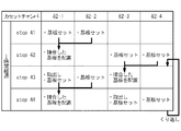
さらに、3枚以上の基板が常温接合される製品を連続して製造する場合において、接合前準備工程である排気待ち時間によるロスを低減して、効率良く製造する方法として、次の方法がある。この動作では、複数のカセットチャンバー82−iのうち、82−1〜82−4を用いる。3枚の基板を1つの基板に連続して常温接合するときの動作では、図17に示されているように、作業者は、まず、ゲートバルブ5とゲートバルブ83−1〜83−4とを閉鎖して、真空ポンプ31を用いて接合チャンバー2の内部に真空雰囲気を生成し、ロードロックチャンバー3の内部に真空雰囲気を生成し、カセットチャンバー82−1〜82−4の内部に大気圧雰囲気を生成する。作業者は、カセットチャンバー82−1〜82−2の蓋を開けて、25枚の基板が装填されたカセット84−1をカセットチャンバー82−1に配置し、25枚の基板が装填されたカセット84−2をカセットチャンバー82−2に配置する。作業者は、カセットチャンバー82−1〜82−2の蓋を閉めて、カセットチャンバー82−1〜82−2の内部に真空雰囲気を生成し、ゲートバルブ5とゲートバルブ83−1〜83−2とを開放する。(step21)作業者は、カセットチャンバー82−3の蓋を開けて、空のカセット84−3をカセットチャンバー82−3に配置する。作業者は、カセットチャンバー82−3の蓋を閉めて、カセットチャンバー82−3の内部に真空雰囲気を生成し、ゲートバルブ5とゲートバルブ83−3を開放する。
Furthermore, in the case of continuously manufacturing products in which three or more substrates are bonded at room temperature, there is the following method as a method for efficiently manufacturing by reducing loss due to exhaust waiting time, which is a pre-bonding preparation step. . In this operation, among the plurality of cassette chambers 82-i, 82-1 to 82-4 are used. In the operation when three substrates are continuously bonded to one substrate at room temperature, as shown in FIG. 17, the operator first selects the
作業者は、搬送装置8を用いて、カセット84−1に装填された基板のうちの1枚の基板を上側基板支持部41に搭載し、カセット84−2に装填された基板のうちの1枚の基板を下側基板支持部42に搭載する。作業者は、ゲートバルブ5を閉鎖して、上側基板支持部41に搭載された基板と下側基板支持部42に搭載された基板とを常温接合して、上側基板支持部41を鉛直上方向に上昇させて、下側基板支持部42に搭載された接合基板を生成する。作業者は、次いで、ゲートバルブ5を開放する。作業者は、搬送装置8を用いて、カセット84−3のうちの空いている棚に下側基板支持部42に搭載されている接合基板を搬送する。このような接合動作は、カセット84−1に装填された基板がすべて常温接合され、カセット84−3のすべての棚に接合基板が装填されるまで繰り返し実行される。(step22)
The operator uses the
作業者は、このような接合動作が実行されている間に、カセットチャンバー82−4の蓋を開けて、25枚の基板が装填されたカセット84−4をカセットチャンバー82−4に配置する。作業者は、カセットチャンバー82−4の蓋を閉めて、カセットチャンバー82−4の内部に真空雰囲気を生成する。(step22) While such a joining operation is being performed, the operator opens the lid of the cassette chamber 82-4 and places the cassette 84-4 loaded with 25 substrates in the cassette chamber 82-4. The operator closes the lid of the cassette chamber 82-4 to generate a vacuum atmosphere inside the cassette chamber 82-4. (Step22)
作業者は、カセット84−1に装填された基板とカセット84−2に装填された基板との常温接合が完了し、かつ、カセットチャンバー82−4の内部に真空雰囲気を生成された後に、カセット84−3に装填され常温接合された接合基板とカセット84−4に装填された基板とを常温接合する。すなわち、作業者は、搬送装置8を用いて、カセット84−3に装填された接合基板のうちの1枚の基板を下側基板支持部42に搭載し、カセット84−4に装填された基板のうちの1枚の基板を上側基板支持部41に搭載する。作業者は、ゲートバルブ5を閉鎖して、上側基板支持部41に搭載された基板と下側基板支持部42に搭載された基板とを常温接合して、上側基板支持部41を鉛直上方向に上昇させて、下側基板支持部42に搭載された接合基板を生成する。作業者は、次いで、ゲートバルブ5を開放する。作業者は、搬送装置8を用いて、カセット84−4のうちの空いている棚に下側基板支持部42に搭載されている接合基板を搬送する。このような接合動作は、カセット84−3、84−4に装填された基板がすべて常温接合されるまで繰り返し実行される。(step23)
The operator completes the room-temperature bonding between the substrate loaded in the cassette 84-1 and the substrate loaded in the cassette 84-2 and generates a vacuum atmosphere in the cassette chamber 82-4. The bonded substrate loaded in 84-3 and bonded at room temperature and the substrate loaded in cassette 84-4 are bonded at room temperature. That is, the operator uses the
作業者は、カセット84−1に装填された基板とカセット84−2に装填された基板との常温接合が完了し、かつ、カセットチャンバー82−4の内部に真空雰囲気を生成された後に、さらに、カセットチャンバー82−1〜82−2の内部に大気圧雰囲気を生成する。作業者は、カセットチャンバー82−1、82−2の蓋を開けて、25枚の基板が装填されたカセット84−1と25枚の基板が装填されたカセット84−2をそれぞれ配置する。作業者は、カセットチャンバー82−1〜82−2の蓋を閉めて、カセットチャンバー82−1〜82−2の内部に真空雰囲気を生成し、ゲートバルブ5とゲートバルブ83−1〜83−2とを開放する。(step23)
After the room temperature bonding between the substrate loaded in the cassette 84-1 and the substrate loaded in the cassette 84-2 is completed and a vacuum atmosphere is generated inside the cassette chamber 82-4, the operator further The atmospheric pressure atmosphere is generated inside the cassette chambers 82-1 to 82-2. The operator opens the lids of the cassette chambers 82-1 and 82-2, and arranges the cassette 84-1 loaded with 25 substrates and the cassette 84-2 loaded with 25 substrates, respectively. The operator closes the lids of the cassette chambers 82-1 to 82-2 to generate a vacuum atmosphere inside the cassette chambers 82-1 to 82-2, and the
作業者は、搬送装置8を用いて、カセット84−1に装填された基板のうちの1枚の基板を上側基板支持部41に搭載し、カセット84−2に装填された基板のうちの1枚の基板を下側基板支持部42に搭載する。作業者は、ゲートバルブ5を閉鎖して、上側基板支持部41に搭載された基板と下側基板支持部42に搭載された基板とを常温接合して、上側基板支持部41を鉛直上方向に上昇させて、下側基板支持部42に搭載された接合基板を生成する。作業者は、次いで、ゲートバルブ5を開放する。作業者は、搬送装置8を用いて、カセット84−3のうちの空いている棚に下側基板支持部42に搭載されている接合基板を搬送する。このような接合動作は、カセット84−1に装填された基板がすべて常温接合され、カセット84−3のすべての棚に接合基板が装填されるまで繰り返し実行される。(step24)
The operator uses the
作業者は、このような接合動作が実行されている間に、カセットチャンバー82−4の蓋を開けて、接合基板が装填されたカセット84−4をカセットチャンバー82−4から取り出し、別の25枚の基板が装填された別のカセット84−4をカセットチャンバー82−4に配置する。作業者は、カセットチャンバー82−4の蓋を閉めて、カセットチャンバー82−4の内部に真空雰囲気を生成する。(step24) While such a joining operation is being performed, the operator opens the lid of the cassette chamber 82-4, takes out the cassette 84-4 loaded with the joining substrate from the cassette chamber 82-4, and then performs another 25. Another cassette 84-4 loaded with one substrate is placed in the cassette chamber 82-4. The operator closes the lid of the cassette chamber 82-4 to generate a vacuum atmosphere inside the cassette chamber 82-4. (Step24)
作業者は、カセット84−1に装填された基板とカセット84−2に装填された基板との常温接合が完了し、かつ、カセットチャンバー82−4の内部に真空雰囲気を生成された後に、再度、カセット84−3に装填され常温接合された接合基板とカセット84−4に装填された基板とを常温接合し、25枚の基板が装填されたカセット84−1と25枚の基板が装填されたカセット84−2をカセットチャンバー82−1、82−2にそれぞれ配置する。 The operator again completes the room-temperature bonding between the substrate loaded in the cassette 84-1 and the substrate loaded in the cassette 84-2 and generates a vacuum atmosphere in the cassette chamber 82-4, and then again. The bonding substrate loaded in the cassette 84-3 and bonded at room temperature and the substrate loaded in the cassette 84-4 are bonded at room temperature, and the cassette 84-1 loaded with 25 substrates and the 25 substrates are loaded. The cassettes 84-2 are placed in the cassette chambers 82-1 and 82-2, respectively.
作業者は、このような動作を繰り返して実行することにより、3枚の基板を1つの基板に連続的に常温接合することができ、かつ3枚の基板が常温接合される製品を連続して製造することができる。すなわち、このような常温接合装置は、3枚の基板が常温接合される製品を連続的に製造するときに、ロードロックチャンバー3の内部を大気圧雰囲気にして再度真空雰囲気にする必要がなく、また接合工程中に同時に、その接合中の基板がそれぞれ配置される2つのカセットチャンバー以外のカセットチャンバーに、次に常温接合される基板が装填されるカセットがセットされることで、排気待ち時間によるロスを低減し、タクトタイムを短縮して、常温接合される基板の単位時間当たりの生産量を常温接合装置1より多くすることができる。なお、step22において接合基板を配置するカセットチャンバーは、4つのカセットチャンバーのどの一つでも良く、この場合、次に接合する基板をセットするカセットチャンバーは、接合基板が配置されておらず、step21において接合する基板を搭載したカセットがセットされていないカセットチャンバーとなる。
By repeatedly executing such an operation, the operator can continuously bond the three substrates to one substrate at room temperature and continuously connect the products to which the three substrates are bonded at room temperature. Can be manufactured. That is, such a room temperature bonding apparatus does not need to make the inside of the
Step23において完成した接合基板を配置するカセットチャンバーは、step22において基板を搭載したカセットがセットされていた二つのカセットチャンバーのうちのどちらの一方でも良い。この場合、次に新たに接合する基板をセットするカセットチャンバーは、step22で基板を搭載したカセットがセットされていた2つのカセットチャンバーを除く残り二つのカセットチャンバーとなる。
The cassette chamber in which the bonded substrate completed in
Step24において接合基板を配置するカセットチャンバーは、Step23で接合された基板が配置されているカセットチャンバーを除くカセットチャンバーのどの一つでも良く、この場合、次に接合する基板をセットするカセットチャンバーは、接合基板が配置されておらず、Step23において新たに接合する基板を搭載したカセットがセットされていないカセットチャンバーとなる。
The cassette chamber in which the bonding substrate is disposed in
4枚の基板を1つの基板に常温接合するときの動作では、図18に示されるように、作業者は、まず、ゲートバルブ5とゲートバルブ83−1〜83−4を閉鎖して、真空ポンプ31を用いて接合チャンバー2の内部に真空雰囲気を生成し、ロードロックチャンバー3の内部に真空雰囲気を生成し、カセットチャンバー82−1〜82−4の内部に大気圧雰囲気を生成する。作業者は、カセットチャンバー82−1〜82−2の蓋を開けて、25枚の基板が装填されたカセット84−1と25枚の基板が装填されたカセット84−2をカセットチャンバー82−1、82−2にそれぞれ配置する。作業者は、カセットチャンバー82−1〜82−2の蓋を閉めて、そのカセットチャンバー82−1〜82−2の内部に真空雰囲気を生成し、ゲートバルブ5とゲートバルブ83−1〜83−2を開放する。(step31)
In the operation when four substrates are bonded to one substrate at room temperature, as shown in FIG. 18, the operator first closes the
作業者は、搬送装置8を用いて、カセット84−1に装填された基板のうちの1枚の基板を上側基板支持部41に搭載し、カセット84−2に装填された基板のうちの1枚の基板を下側基板支持部42に搭載する。作業者は、ゲートバルブ5を閉鎖して、上側基板支持部41に搭載された基板と下側基板支持部42に搭載された基板とを常温接合して、上側基板支持部41を鉛直上方向に上昇させて、下側基板支持部42に搭載された接合基板を生成する。作業者は、次いで、ゲートバルブ5を開放する。作業者は、搬送装置8を用いて、カセット84−1のうちの空いている棚に下側基板支持部42に搭載されている接合基板を搬送する。このような接合動作は、カセット84−1に装填された基板がすべて常温接合され、カセット84−1のすべての棚に接合基板が装填されるまで繰り返し実行される。(step32)
The operator uses the
作業者は、このような接合動作が実行されている間に、カセットチャンバー82−3の蓋を開けて、25枚の基板が装填されたカセット84−3をカセットチャンバー82−3に配置する。作業者は、カセットチャンバー82−3の蓋を閉めて、カセットチャンバー82−3の内部に真空雰囲気を生成する。(step32) While such a joining operation is being performed, the operator opens the lid of the cassette chamber 82-3 and places the cassette 84-3 loaded with 25 substrates in the cassette chamber 82-3. The operator closes the lid of the cassette chamber 82-3 to generate a vacuum atmosphere inside the cassette chamber 82-3. (Step32)
作業者は、カセット84−1に装填された基板とカセット84−2に装填された基板との常温接合が完了し、かつ、カセットチャンバー82−3の内部に真空雰囲気を生成された後に、カセット84−1に装填され常温接合された接合基板とカセット84−3に装填された基板とを常温接合する。すなわち、作業者は、搬送装置8を用いて、カセット84−1に装填された接合基板のうちの1枚の基板を下側基板支持部42に搭載し、カセット84−3に装填された基板のうちの1枚の基板を上側基板支持部41に搭載する。作業者は、ゲートバルブ5を閉鎖して、上側基板支持部41に搭載された基板と下側基板支持部42に搭載された基板とを常温接合して、上側基板支持部41を鉛直上方向に上昇させて、下側基板支持部42に搭載された接合基板を生成する。作業者は、次いで、ゲートバルブ5を開放する。作業者は、搬送装置8を用いて、カセット84−3のうちの空いている棚に下側基板支持部42に搭載されている接合基板を搬送する。このような接合動作は、カセット84−1に装填された基板がすべて常温接合されるまで繰り返し実行される。(step33)
After the room temperature bonding between the substrate loaded in the cassette 84-1 and the substrate loaded in the cassette 84-2 is completed, and the operator creates a vacuum atmosphere inside the cassette chamber 82-3, the operator The bonded substrate loaded in 84-1 and bonded at room temperature and the substrate loaded in cassette 84-3 are bonded at room temperature. That is, the operator uses the
作業者は、カセット84−1に装填された基板とカセット84−2に装填された基板との常温接合が完了し、かつ、カセットチャンバー82−3の内部に真空雰囲気を生成された後に、さらに、カセットチャンバー82−4の内部に大気圧雰囲気を生成する。作業者は、カセットチャンバー82−4の蓋を開けて、25枚の基板が装填されたカセット84−4をカセットチャンバー82−4に配置する。作業者は、カセットチャンバー82−4の蓋を閉めて、カセットチャンバー82−4の内部に真空雰囲気を生成し、ゲートバルブ5とゲートバルブ83−4を開放する。(step33)
After the room temperature bonding between the substrate loaded in the cassette 84-1 and the substrate loaded in the cassette 84-2 is completed and a vacuum atmosphere is generated inside the cassette chamber 82-3, the operator further Then, an atmospheric pressure atmosphere is generated inside the cassette chamber 82-4. The operator opens the lid of the cassette chamber 82-4 and places the cassette 84-4 loaded with 25 substrates in the cassette chamber 82-4. The operator closes the lid of the cassette chamber 82-4, generates a vacuum atmosphere inside the cassette chamber 82-4, and opens the
作業者は、搬送装置8を用いて、カセット84−3に装填された接合基板のうちの1枚の基板を下側基板支持部42に搭載し、カセット84−4に装填された基板のうちの1枚の基板を上側基板支持部41に搭載する。作業者は、ゲートバルブ5を閉鎖して、上側基板支持部41に搭載された基板と下側基板支持部42に搭載された基板とを常温接合して、上側基板支持部41を鉛直上方向に上昇させて、下側基板支持部42に搭載された接合基板を生成する。作業者は、次いで、ゲートバルブ5を開放する。作業者は、搬送装置8を用いて、カセット84−4のうちの空いている棚に下側基板支持部42に搭載されている接合基板を搬送する。このような接合動作は、カセット84−3に装填された接合基板がすべて常温接合されるまで繰り返し実行される。(step34)
The operator uses the
作業者は、このような接合動作が実行されている間に、カセットチャンバー82−1、82−2の蓋を開けて、空のカセット84−1〜84−2をカセットチャンバー82−1、82−2から取り出し、別の25枚の基板が装填された別のカセット84−1〜84−2をそのカセットチャンバー82−1、82−2に配置する。作業者は、カセットチャンバー82−1、82−2の蓋を閉めて、そのカセットチャンバー82−1、82−2の内部に真空雰囲気を生成する。(step34) While such a joining operation is being performed, the operator opens the lids of the cassette chambers 82-1 and 82-2 to place empty cassettes 84-1 to 84-2 in the cassette chambers 82-1 and 82-2. -2 and another cassettes 84-1 to 84-2 loaded with another 25 substrates are placed in the cassette chambers 82-1 and 82-2. The operator closes the lids of the cassette chambers 82-1 and 82-2, and generates a vacuum atmosphere inside the cassette chambers 82-1 and 82-2. (Step 34)
作業者は、搬送装置8を用いて、カセット84−1に装填された基板のうちの1枚の基板を上側基板支持部41に搭載し、カセット84−2に装填された基板のうちの1枚の基板を下側基板支持部42に搭載する。作業者は、ゲートバルブ5を閉鎖して、上側基板支持部41に搭載された基板と下側基板支持部42に搭載された基板とを常温接合して、上側基板支持部41を鉛直上方向に上昇させて、下側基板支持部42に搭載された接合基板を生成する。作業者は、次いで、ゲートバルブ5を開放する。作業者は、搬送装置8を用いて、カセット84−1のうちの空いている棚に下側基板支持部42に搭載されている接合基板を搬送する。このような接合動作は、カセット84−1に装填された基板がすべて常温接合され、カセット84−1のすべての棚に接合基板が装填されるまで繰り返し実行される。(step35)
The operator uses the
作業者は、このような接合動作が実行されている間に、カセットチャンバー82−3の蓋を開けて、25枚の基板が装填されたカセット84−3をカセットチャンバー82−3に配置する。作業者は、カセットチャンバー82−3の蓋を閉めて、カセットチャンバー82−3の内部に真空雰囲気を生成する。作業者は、このような接合動作が実行されている間に、さらに、カセットチャンバー82−4の蓋を開けて、接合基板が装填されたカセット84−4をカセットチャンバー82−4から取り出す。(step35) While such a joining operation is being performed, the operator opens the lid of the cassette chamber 82-3 and places the cassette 84-3 loaded with 25 substrates in the cassette chamber 82-3. The operator closes the lid of the cassette chamber 82-3 to generate a vacuum atmosphere inside the cassette chamber 82-3. While such a bonding operation is being performed, the operator further opens the lid of the cassette chamber 82-4 and takes out the cassette 84-4 loaded with the bonding substrate from the cassette chamber 82-4. (Step 35)
作業者は、カセット84−1に装填された基板とカセット84−2に装填された基板との常温接合が完了し、かつ、カセットチャンバー82−3の内部に真空雰囲気を生成された後に、再度、カセット84−1に装填され常温接合された接合基板とカセット84−3に装填された基板とを常温接合し、25枚の基板が装填されたカセット84−4をカセットチャンバー82−4に配置する。 After the room temperature bonding between the substrate loaded in the cassette 84-1 and the substrate loaded in the cassette 84-2 is completed and a vacuum atmosphere is generated inside the cassette chamber 82-3, the operator again The bonding substrate loaded in the cassette 84-1 and bonded at room temperature and the substrate loaded in the cassette 84-3 are bonded at room temperature, and the cassette 84-4 loaded with 25 substrates is placed in the cassette chamber 82-4. To do.
作業者は、このような動作を繰り返して実行することにより、4枚の基板を1つの基板に連続的に常温接合することができ、かつ4枚の基板が常温接合される製品を連続して製造することができる。すなわち、このような常温接合装置は、4枚の基板が常温接合される製品を連続的に製造するときに、ロードロックチャンバー3の内部を大気圧雰囲気にして再度真空雰囲気にする必要がなく、また接合工程中に同時に、その接合中の基板がそれぞれ配置される2つのカセットチャンバー以外のカセットチャンバーに、次に常温接合される基板が装填されるカセットがセットされることで、排気待ち時間によるロスを低減し、タクトタイムを短縮して、常温接合される基板の単位時間当たりの生産量を常温接合装置1より多くすることができる。なお、step32、step33において接合基板を配置するカセットチャンバーは、4つのカセットチャンバーのどの一つでも良く、この場合、次に接合する基板をセットするカセットチャンバーは、接合基板を配置しておらず、前のstepにおいて基板を搭載したカセットがセットされていないカセットチャンバーとなる。Step34において完成した接合基板を配置するカセットチャンバーは、step33において基板を搭載したカセットがセットされた二つのカセットチャンバーのうちのどちらの一方でも良い。この場合、次に新たに接合する基板をセットするカセットチャンバーは、step33で基板を搭載したカセットがセットされた二つのカセットチャンバーを除く残りの二つのカセットチャンバーとなる。Step35において接合基板を配置するカセットチャンバーは、Step34で接合された基板が配置されているカセットチャンバーを除くカセットチャンバーのどの一つでも良く、この場合、次に接合する基板をセットするカセットチャンバーは、接合基板を配置しておらず、Step34において新たに接合する基板を搭載したカセットをセットしていないカセットチャンバーとなる。
By repeatedly performing such an operation, the operator can continuously bond the four substrates to one substrate at room temperature and continuously connect the products to which the four substrates are bonded at room temperature. Can be manufactured. That is, such a room temperature bonding apparatus does not need to make the inside of the
このような常温接合装置は、同様にして、5枚以上の基板を1つの基板に連続的に常温接合することができる。すなわち、このような常温接合装置は、5枚以上の基板が常温接合される製品を連続的に製造するときに、ロードロックチャンバー3の内部を大気圧雰囲気にして再度真空雰囲気にする必要がなく、また接合工程中に同時に、その接合中の基板がそれぞれ配置される2つのカセットチャンバー以外のカセットチャンバーに、次に常温接合される基板が装填されるカセットがセットされることで、排気待ち時間によるロスを低減し、タクトタイムを短縮して、常温接合される基板の単位時間当たりの生産量を常温接合装置1より多くすることができる。
Similarly, such a room temperature bonding apparatus can continuously bond five or more substrates to a single substrate at room temperature. That is, such a room temperature bonding apparatus eliminates the need to make the inside of the
2枚の基板を1つの基板に常温接合するときの動作では、図19に示されるように、作業者は、まず、ゲートバルブ5とゲートバルブ83−1〜83−4とを閉鎖して、真空ポンプ31を用いて接合チャンバー2の内部に真空雰囲気を生成し、ロードロックチャンバー3の内部に真空雰囲気を生成し、カセットチャンバー82−1〜82−4の内部に大気圧雰囲気を生成する。作業者は、カセットチャンバー82−1〜82−2の蓋を開けて、25枚の基板が装填されたカセット84−1をカセットチャンバー82−1に配置し、25枚の基板が装填されたカセット84−2をカセットチャンバー82−2に配置する。作業者は、カセットチャンバー82−1〜82−2の蓋を閉めて、カセットチャンバー82−1〜82−2の内部に真空雰囲気を生成し、ゲートバルブ5とゲートバルブ83−1〜83−2とを開放する。(step41)
In the operation when bonding two substrates to a single substrate at room temperature, as shown in FIG. 19, the operator first closes the
作業者は、搬送装置8を用いて、カセット84−1に装填された基板のうちの1枚の基板を上側基板支持部41に搭載し、カセット84−2に装填された基板のうちの1枚の基板を下側基板支持部42に搭載する。作業者は、ゲートバルブ5を閉鎖して、上側基板支持部41に搭載された基板と下側基板支持部42に搭載された基板とを常温接合して、上側基板支持部41を鉛直上方向に上昇させて、下側基板支持部42に搭載された接合基板を生成する。作業者は、次いで、ゲートバルブ5を開放する。作業者は、搬送装置8を用いて、カセット84−1のうちの空いている棚に下側基板支持部42に搭載されている接合基板を搬送する。このような接合動作は、カセット84−1に装填された基板がすべて常温接合されるまで繰り返し実行される。(step42)
The operator uses the
作業者は、このような接合動作が実行されている間に、カセットチャンバー82−3〜82−4の蓋を開けて、25枚の基板が装填されたカセット84−3をカセットチャンバー82−3に配置し、25枚の基板が装填されたカセット84−4をカセットチャンバー82−4に配置する。作業者は、カセットチャンバー82−3〜82−4の蓋を閉めて、カセットチャンバー82−3〜82−4の内部に真空雰囲気を生成する。(step42) While such a joining operation is being performed, the operator opens the lids of the cassette chambers 82-3 to 82-4 and inserts the cassette 84-3 loaded with 25 substrates into the cassette chamber 82-3. The cassette 84-4 loaded with 25 substrates is placed in the cassette chamber 82-4. The operator closes the lids of the cassette chambers 82-3 to 82-4 and generates a vacuum atmosphere inside the cassette chambers 82-3 to 82-4. (Step42)
作業者は、カセット84−1に装填された基板とカセット84−2に装填された基板との常温接合が完了し、かつ、カセットチャンバー82−3〜82−4の内部に真空雰囲気を生成された後に、カセット84−3に装填された基板とカセット84−4に装填された基板とを常温接合する。すなわち、作業者は、搬送装置8を用いて、カセット84−3に装填された基板のうちの1枚の基板を上側基板支持部41に搭載し、カセット84−4に装填された基板のうちの1枚の基板を下側基板支持部42に搭載する。作業者は、ゲートバルブ5を閉鎖して、上側基板支持部41に搭載された基板と下側基板支持部42に搭載された基板とを常温接合して、上側基板支持部41を鉛直上方向に上昇させて、下側基板支持部42に搭載された接合基板を生成する。作業者は、次いで、ゲートバルブ5を開放する。作業者は、搬送装置8を用いて、カセット84−3のうちの空いている棚に下側基板支持部42に搭載されている接合基板を搬送する。このような接合動作は、カセット84−3に装填された基板がすべて常温接合されるまで繰り返し実行される。(step43)
The operator completes normal temperature bonding between the substrate loaded in the cassette 84-1 and the substrate loaded in the cassette 84-2, and a vacuum atmosphere is generated inside the cassette chambers 82-3 to 82-4. After that, the substrate loaded in the cassette 84-3 and the substrate loaded in the cassette 84-4 are bonded at room temperature. That is, the operator uses the
作業者は、このような接合動作が実行されている間に、カセットチャンバー82−1の蓋を開けて、接合基板が装填されたカセット84−1をカセットチャンバー82−1から取り出し、別の25枚の基板が装填された別のカセット84−1をカセットチャンバー82−1に配置し、25枚の基板が装填されたカセット84−2をカセットチャンバー82−2に配置する。作業者は、カセットチャンバー82−1〜82−2の蓋を閉めて、カセットチャンバー82−1〜82−2の内部に真空雰囲気を生成し、ゲートバルブ5とゲートバルブ83−1〜83−2とを開放する。(step43)
While such a joining operation is being performed, the operator opens the lid of the cassette chamber 82-1, takes out the cassette 84-1 loaded with the joining substrate from the cassette chamber 82-1, and performs another 25. Another cassette 84-1 loaded with one substrate is placed in the cassette chamber 82-1, and a cassette 84-2 loaded with 25 substrates is placed in the cassette chamber 82-2. The operator closes the lids of the cassette chambers 82-1 to 82-2 to generate a vacuum atmosphere inside the cassette chambers 82-1 to 82-2, and the
作業者は、搬送装置8を用いて、カセット84−1に装填された基板のうちの1枚の基板を上側基板支持部41に搭載し、カセット84−2に装填された基板のうちの1枚の基板を下側基板支持部42に搭載する。作業者は、ゲートバルブ5を閉鎖して、上側基板支持部41に搭載された基板と下側基板支持部42に搭載された基板とを常温接合して、上側基板支持部41を鉛直上方向に上昇させて、下側基板支持部42に搭載された接合基板を生成する。作業者は、次いで、ゲートバルブ5を開放する。作業者は、搬送装置8を用いて、カセット84−1のうちの空いている棚に下側基板支持部42に搭載されている接合基板を搬送する。このような接合動作は、カセット84−1に装填された基板がすべて常温接合され、カセット84−1のすべての棚に接合基板が装填されるまで繰り返し実行される。(step44)
The operator uses the
作業者は、このような接合動作が実行されている間に、カセットチャンバー82−3の蓋を開けて、接合基板が装填されたカセット84−3をカセットチャンバー82−3から取り出し、別の25枚の基板が装填された別のカセット84−3をカセットチャンバー82−3に配置し、25枚の基板が装填されたカセット84−4をカセットチャンバー82−4に配置する。作業者は、カセットチャンバー82−3〜82−4の蓋を閉めて、カセットチャンバー82−3〜82−4の内部に真空雰囲気を生成する。(step44) While such a joining operation is being performed, the operator opens the lid of the cassette chamber 82-3, takes out the cassette 84-3 loaded with the joining substrate from the cassette chamber 82-3, and performs another 25. Another cassette 84-3 loaded with one substrate is placed in the cassette chamber 82-3, and a cassette 84-4 loaded with 25 substrates is placed in the cassette chamber 82-4. The operator closes the lids of the cassette chambers 82-3 to 82-4 and generates a vacuum atmosphere inside the cassette chambers 82-3 to 82-4. (Step44)
作業者は、このような動作(step43、44)を繰り返して実行することにより、2枚の基板が常温接合される製品を連続して製造することができる。このように、常温接合装置81を用いて2枚の基板を1つの基板に常温接合するときの動作では、2つの基板が常温接合されている間に、その2つの基板がそれぞれ配置される2つのカセットチャンバー以外の2つのカセットチャンバーに次に常温接合される基板が装填される2つのカセットがそれぞれセットされる。既述の実施の形態における常温接合装置1では、2枚の基板を1つの基板に常温接合するときに、2枚の基板が常温接合された接合基板が生成された後に次の基板をセットするためにロードロックチャンバー3の内部を大気圧雰囲気にして再度真空雰囲気にする必要がある。常温接合装置81は、2枚の基板が常温接合される製品を連続的に製造するときに、ロードロックチャンバー3の内部を大気圧雰囲気にして再度真空雰囲気にする必要がなく、タクトタイムを短縮して、常温接合される基板の単位時間当たりの生産量を常温接合装置1より多くすることができる。
The operator can continuously manufacture products in which two substrates are bonded at room temperature by repeatedly executing such operations (
なお、Step42、step44において完成した接合基板を配置するカセットチャンバーは、step41、step43で新たに接合する基板を搭載したカセットをセットしたカセットチャンバーのうちのどちらの一方でも良い。この場合、次に新たに接合する基板をセットするカセットチャンバーは、step41、step43で新たに接合する基板を搭載したカセットをセットしたカセットチャンバーを除くカセットチャンバーとなる。
Note that the cassette chamber in which the bonded substrates completed in
なお、このような2枚の基板を1つの基板に常温接合するときの動作は、さらに、カセットチャンバー82−1〜82−2が2つのカセット84−1〜84−2を内部に配置することができる1つの第1カセットチャンバーに置換され、カセットチャンバー82−3〜82−4が2つのカセット84−3〜84−4を内部に配置することができる1つの第2カセットチャンバーに置換されているさらに他の常温接合装置を用いても実行されることができる。このとき、その常温接合装置は、第1ゲートバルブと第2ゲートバルブとを備えている。その第1ゲートバルブは、その第1カセットチャンバーとロードロックチャンバー3との間に介設され、その第1カセットチャンバーの内部とロードロックチャンバー3の内部とを接続するゲートを閉鎖し、または、開放する。その第2ゲートバルブは、その第2カセットチャンバーとロードロックチャンバー3との間に介設され、その第2カセットチャンバーの内部とロードロックチャンバー3の内部とを接続するゲートを閉鎖し、または、開放する。このような常温接合装置は、既述の3枚以上の基板を1つの基板に常温接合するときの動作を実行することができないが、構造がさらに簡単であり、2枚連続接合動作にとって好適である。
In addition, the operation when such two substrates are bonded to one substrate at room temperature is that the cassette chambers 82-1 to 82-2 further arrange the two cassettes 84-1 to 84-2 inside. Is replaced with one first cassette chamber, and cassette chambers 83-3 to 82-4 are replaced with one second cassette chamber into which two cassettes 84-3 to 84-4 can be placed. It can also be implemented using other room temperature bonding devices. At this time, the room temperature bonding apparatus includes a first gate valve and a second gate valve. The first gate valve is interposed between the first cassette chamber and the
本発明による常温接合装置の実施のさらに他の形態は、既述の実施の形態における常温接合装置81のカセットチャンバー82−1〜82−2が1つの連結カセットチャンバーに置換されている。その連結カセットチャンバーは、2つのカセット84−1〜84−2を内部に配置することができる。このとき、その常温接合装置は、連結ゲートバルブを備えている。その連結ゲートバルブは、その連結カセットチャンバーとロードロックチャンバー3との間に介設され、その連結カセットチャンバーの内部とロードロックチャンバー3の内部とを接続するゲートを閉鎖し、または、開放する。
In still another embodiment of the room temperature bonding apparatus according to the present invention, the cassette chambers 82-1 to 82-2 of the room
このような常温接合装置は、既述の実施の形態における常温接合装置81と同様に、2枚の基板を1つの基板に常温接合するときの動作と、3枚以上の基板を1つの基板に常温接合するときの動作と、これらの接合基板を連続して製造する動作を実行することができる。
Such a room-temperature bonding apparatus, like the room-
2枚の基板を1つの基板に常温接合するときの動作では、作業者は、まず、ゲートバルブ5とゲートバルブ83−3〜83−4とその連結ゲートバルブとを閉鎖して、真空ポンプ31を用いて接合チャンバー2の内部に真空雰囲気を生成し、ロードロックチャンバー3の内部に真空雰囲気を生成し、カセットチャンバー82−3〜82−4とその連結カセットチャンバーの内部に大気圧雰囲気を生成する。作業者は、その連結カセットチャンバーの蓋を開けて、25枚の基板が装填されたカセット84−1と25枚の基板が装填されたカセット84−2とをその連結カセットチャンバーに配置する。作業者は、その連結カセットチャンバーの蓋を閉めて、その連結カセットチャンバーの内部に真空雰囲気を生成し、ゲートバルブ5とその連結ゲートバルブとを開放する。
In the operation when two substrates are bonded to one substrate at room temperature, the operator first closes the
作業者は、搬送装置8を用いて、カセット84−1に装填された基板のうちの1枚の基板を上側基板支持部41に搭載し、カセット84−2に装填された基板のうちの1枚の基板を下側基板支持部42に搭載する。作業者は、ゲートバルブ5を閉鎖して、上側基板支持部41に搭載された基板と下側基板支持部42に搭載された基板とを常温接合して、上側基板支持部41を鉛直上方向に上昇させて、下側基板支持部42に搭載された接合基板を生成する。作業者は、次いで、ゲートバルブ5を開放する。作業者は、搬送装置8を用いて、カセット84−1のうちの空いている棚に下側基板支持部42にセットされている接合基板を搬送する。このような接合動作は、カセット84−1に装填された基板がすべて常温接合されるまで繰り返し実行される。
The operator uses the
作業者は、このような接合動作が実行されている間に、カセットチャンバー82−3〜82−4の蓋を開けて、25枚の基板が装填されたカセット84−3をカセットチャンバー82−3に配置し、25枚の基板が装填されたカセット84−4をカセットチャンバー82−4に配置する。作業者は、カセットチャンバー82−3〜82−4の蓋を閉めて、カセットチャンバー82−3〜82−4の内部に真空雰囲気を生成する。 While such a joining operation is being performed, the operator opens the lids of the cassette chambers 82-3 to 82-4 and inserts the cassette 84-3 loaded with 25 substrates into the cassette chamber 82-3. The cassette 84-4 loaded with 25 substrates is placed in the cassette chamber 82-4. The operator closes the lids of the cassette chambers 82-3 to 82-4 and generates a vacuum atmosphere inside the cassette chambers 82-3 to 82-4.
作業者は、カセット84−1に装填された基板とカセット84−2に装填された基板との常温接合が完了し、かつ、カセットチャンバー82−3〜82−4の内部に真空雰囲気を生成された後に、カセット84−3に装填された基板とカセット84−4に装填された基板とを常温接合する。すなわち、作業者は、搬送装置8を用いて、カセット84−4に装填された基板のうちの1枚の基板を上側基板支持部41に搭載し、カセット84−3に装填された基板のうちの1枚の基板を下側基板支持部42に搭載する。作業者は、ゲートバルブ5を閉鎖して、上側基板支持部41に搭載された基板と下側基板支持部42に搭載された基板とを常温接合して、上側基板支持部41を鉛直上方向に上昇させて、下側基板支持部42に搭載された接合基板を生成する。作業者は、次いで、ゲートバルブ5を開放する。作業者は、搬送装置8を用いて、カセット84−3のうちの空いている棚に下側基板支持部42に搭載されている接合基板を搬送する。このような接合動作は、カセット84−3に装填された基板がすべて常温接合されるまで繰り返し実行される。
The operator completes normal temperature bonding between the substrate loaded in the cassette 84-1 and the substrate loaded in the cassette 84-2, and a vacuum atmosphere is generated inside the cassette chambers 82-3 to 82-4. After that, the substrate loaded in the cassette 84-3 and the substrate loaded in the cassette 84-4 are bonded at room temperature. That is, the operator uses the
作業者は、このような接合動作が実行されている間に、その連結カセットチャンバーの蓋を開けて、接合基板が装填されたカセット84−1を連結カセットチャンバーから取り出し、別の25枚の基板が装填された別のカセット84−1と、25枚の基板が装填されたカセット84−2を連結カセットチャンバーに配置する。作業者は、連結カセットチャンバーの蓋を閉めて、その連結カセットチャンバーの内部に真空雰囲気を生成し、ゲートバルブ5とその連結ゲートバルブとを開放する。
While such a bonding operation is being performed, the operator opens the lid of the connected cassette chamber, takes out the cassette 84-1 loaded with the bonded substrate from the connected cassette chamber, and another 25 substrates. Is placed in the connected cassette chamber, and another cassette 84-1 loaded with 25 and a substrate 84-2 loaded with 25 substrates. The operator closes the lid of the connected cassette chamber, generates a vacuum atmosphere inside the connected cassette chamber, and opens the
作業者は、搬送装置8を用いて、カセット84−1に装填された基板のうちの1枚の基板を上側基板支持部41に搭載し、カセット84−2に装填された基板のうちの1枚の基板を下側基板支持部42に搭載する。作業者は、ゲートバルブ5を閉鎖して、上側基板支持部41に搭載された基板と下側基板支持部42に搭載された基板とを常温接合して、上側基板支持部41を鉛直上方向に上昇させて、下側基板支持部42に搭載された接合基板を生成する。作業者は、次いで、ゲートバルブ5を開放する。作業者は、搬送装置8を用いて、カセット84−1のうちの空いている棚に下側基板支持部42に搭載されている接合基板を搬送する。このような接合動作は、カセット84−1に装填された基板がすべて常温接合され、カセット84−1のすべての棚に接合基板が装填されるまで繰り返し実行される。
The operator uses the
作業者は、このような接合動作が実行されている間に、カセットチャンバー82−3の蓋を開けて、接合基板が装填されたカセット84−3をカセットチャンバー82−3から取り出し、別の25枚の基板が装填された別のカセット84−3をカセットチャンバー82−3に配置し、25枚の基板が装填されたカセット84−4をカセットチャンバー82−4に配置する。作業者は、カセットチャンバー82−3〜82−4の蓋を閉めて、カセットチャンバー82−3〜82−4の内部に真空雰囲気を生成する。 While such a joining operation is being performed, the operator opens the lid of the cassette chamber 82-3, takes out the cassette 84-3 loaded with the joining substrate from the cassette chamber 82-3, and performs another 25. Another cassette 84-3 loaded with one substrate is placed in the cassette chamber 82-3, and a cassette 84-4 loaded with 25 substrates is placed in the cassette chamber 82-4. The operator closes the lids of the cassette chambers 82-3 to 82-4 and generates a vacuum atmosphere inside the cassette chambers 82-3 to 82-4.
作業者は、このような動作を繰り返して実行することにより、2枚の基板が常温接合される製品を連続して製造することができる。このような常温接合装置では、2つの基板が常温接合されている間に、その2つの基板がそれぞれ配置される2つのカセットチャンバー以外の2つのカセットチャンバーに次に常温接合される基板が装填される2つのカセットがそれぞれセットされる。このため、このような常温接合装置は、2枚の基板が常温接合される製品を連続的に製造するときに、ロードロックチャンバー3の内部を大気圧雰囲気にして再度真空雰囲気にする必要がなく、タクトタイムを短縮して、常温接合される基板の単位時間当たりの生産量を常温接合装置1より多くすることができる。このような常温接合装置は、さらに、常温接合装置81より構造が簡単であり、装置設計・製造・メンテナンスコスト低減の観点から好ましい。
An operator can continuously manufacture products in which two substrates are bonded at room temperature by repeatedly executing such an operation. In such a room temperature bonding apparatus, while two substrates are bonded at room temperature, two cassette chambers other than the two cassette chambers in which the two substrates are respectively placed are loaded with a substrate to be bonded next at room temperature. Two cassettes are set. For this reason, such a room temperature bonding apparatus does not require the inside of the
3枚の基板を1つの基板に常温接合するときの動作では、作業者は、まず、ゲートバルブ5とゲートバルブ83−3〜83−4とその連結ゲートバルブとを閉鎖して、真空ポンプ31を用いて接合チャンバー2の内部に真空雰囲気を生成し、ロードロックチャンバー3の内部に真空雰囲気を生成し、カセットチャンバー82−3〜82−4とその連結カセットチャンバーの内部に大気圧雰囲気を生成する。作業者は、その連結カセットチャンバーの蓋を開けて、25枚の基板が装填されたカセット84−1と25枚の基板が装填されたカセット84−2をその連結カセットチャンバーに配置する。作業者は、その連結カセットチャンバーの蓋を閉めて、その連結カセットチャンバーの内部に真空雰囲気を生成し、ゲートバルブ5とその連結ゲートバルブを開放する。作業者は、カセットチャンバー82−3の蓋を開けて、空のカセット84−3をカセットチャンバー82−3に配置する。作業者は、カセットチャンバー82−3の蓋を閉めて、カセットチャンバー82−3の内部に真空雰囲気を生成し、ゲートバルブ5とゲートバルブ83−3を開放する。
In an operation when three substrates are bonded to one substrate at room temperature, the operator first closes the
作業者は、搬送装置8を用いて、カセット84−1に装填された基板のうちの1枚の基板を上側基板支持部41に搭載し、カセット84−2に装填された基板のうちの1枚の基板を下側基板支持部42に搭載する。作業者は、ゲートバルブ5を閉鎖して、上側基板支持部41に搭載された基板と下側基板支持部42に搭載された基板とを常温接合して、上側基板支持部41を鉛直上方向に上昇させて、下側基板支持部42に搭載された接合基板を生成する。作業者は、次いで、ゲートバルブ5を開放する。作業者は、搬送装置8を用いて、カセット84−3のうちの空いている棚に下側基板支持部42に搭載されている接合基板を搬送する。このような接合動作は、カセット84−1に装填された基板がすべて常温接合され、カセット84−3のすべての棚に接合基板が装填されるまで繰り返し実行される。
The operator uses the
作業者は、このような接合動作が実行されている間に、カセットチャンバー82−4の蓋を開けて、25枚の基板が装填されたカセット84−4をカセットチャンバー82−4に配置する。作業者は、カセットチャンバー82−4の蓋を閉めて、カセットチャンバー82−4の内部に真空雰囲気を生成する。 While such a joining operation is being performed, the operator opens the lid of the cassette chamber 82-4 and places the cassette 84-4 loaded with 25 substrates in the cassette chamber 82-4. The operator closes the lid of the cassette chamber 82-4 to generate a vacuum atmosphere inside the cassette chamber 82-4.
作業者は、カセット84−1に装填された基板とカセット84−2に装填された基板との常温接合が完了し、かつ、カセットチャンバー82−4の内部に真空雰囲気を生成された後に、カセット84−3に装填され常温接合された接合基板とカセット84−4に装填された基板とを常温接合する。すなわち、作業者は、搬送装置8を用いて、カセット84−3に装填された接合基板のうちの1枚の基板を下側基板支持部42に搭載し、カセット84−4に装填された基板のうちの1枚の基板を上側基板支持部41に搭載する。作業者は、ゲートバルブ5を閉鎖して、上側基板支持部41に搭載された基板と下側基板支持部42に搭載された基板とを常温接合して、上側基板支持部41を鉛直上方向に上昇させて、下側基板支持部42に搭載された接合基板を生成する。作業者は、次いで、ゲートバルブ5を開放する。作業者は、搬送装置8を用いて、カセット84−4のうちの空いている棚に下側基板支持部42に搭載されている接合基板を搬送する。このような接合動作は、カセット84−3、84−4に装填された基板がすべて常温接合されるまで繰り返し実行される。
The operator completes the room-temperature bonding between the substrate loaded in the cassette 84-1 and the substrate loaded in the cassette 84-2 and generates a vacuum atmosphere in the cassette chamber 82-4. The bonded substrate loaded in 84-3 and bonded at room temperature and the substrate loaded in cassette 84-4 are bonded at room temperature. That is, the operator uses the
作業者は、カセット84−1に装填された基板とカセット84−2に装填された基板との常温接合が完了し、かつ、カセットチャンバー82−4の内部に真空雰囲気を生成された後に、さらに、その連結カセットチャンバーの内部に大気圧雰囲気を生成する。作業者は、その連結カセットチャンバーの蓋を開けて、25枚の基板が装填されたカセット84−1と25枚の基板が装填されたカセット84−2をその連結カセットチャンバーに配置する。作業者は、その連結カセットチャンバーの蓋を閉めて、その連結カセットチャンバーの内部に真空雰囲気を生成し、ゲートバルブ5とその連結ゲートバルブを開放する。
After the room temperature bonding between the substrate loaded in the cassette 84-1 and the substrate loaded in the cassette 84-2 is completed and a vacuum atmosphere is generated inside the cassette chamber 82-4, the operator further An atmospheric pressure atmosphere is generated inside the connected cassette chamber. The operator opens the lid of the connected cassette chamber, and places the cassette 84-1 loaded with 25 substrates and the cassette 84-2 loaded with 25 substrates in the connected cassette chamber. The operator closes the lid of the connected cassette chamber, generates a vacuum atmosphere in the connected cassette chamber, and opens the
作業者は、搬送装置8を用いて、カセット84−1に装填された基板のうちの1枚の基板を上側基板支持部41に搭載し、カセット84−2に装填された基板のうちの1枚の基板を下側基板支持部42に搭載する。作業者は、ゲートバルブ5を閉鎖して、上側基板支持部41に搭載された基板と下側基板支持部42に搭載された基板とを常温接合して、上側基板支持部41を鉛直上方向に上昇させて、下側基板支持部42に搭載された接合基板を生成する。作業者は、次いで、ゲートバルブ5を開放する。作業者は、搬送装置8を用いて、カセット84−3のうちの空いている棚に下側基板支持部42に搭載されている接合基板を搬送する。このような接合動作は、カセット84−1に装填された基板がすべて常温接合され、カセット84−3のすべての棚に接合基板が装填されるまで繰り返し実行される。
The operator uses the
作業者は、このような接合動作が実行されている間に、カセットチャンバー82−4の蓋を開けて、接合基板が装填されたカセット84−4をカセットチャンバー82−4から取り出し、別の25枚の基板が装填された別のカセット84−4をカセットチャンバー82−4に配置する。作業者は、カセットチャンバー82−4の蓋を閉めて、カセットチャンバー82−4の内部に真空雰囲気を生成する。 While such a joining operation is being performed, the operator opens the lid of the cassette chamber 82-4, takes out the cassette 84-4 loaded with the joining substrate from the cassette chamber 82-4, and then performs another 25. Another cassette 84-4 loaded with one substrate is placed in the cassette chamber 82-4. The operator closes the lid of the cassette chamber 82-4 to generate a vacuum atmosphere inside the cassette chamber 82-4.
作業者は、カセット84−1に装填された基板とカセット84−2に装填された基板との常温接合が完了し、かつ、カセットチャンバー82−4の内部に真空雰囲気を生成された後に、再度、カセット84−3に装填され常温接合された接合基板とカセット84−4に装填された基板とを常温接合し、25枚の基板が装填されたカセット84−1と25枚の基板が装填されたカセット84−2をその連結カセットチャンバーに配置する。 The operator again completes the room-temperature bonding between the substrate loaded in the cassette 84-1 and the substrate loaded in the cassette 84-2 and generates a vacuum atmosphere in the cassette chamber 82-4, and then again. The bonding substrate loaded in the cassette 84-3 and bonded at room temperature and the substrate loaded in the cassette 84-4 are bonded at room temperature, and the cassette 84-1 loaded with 25 substrates and the 25 substrates are loaded. The cassette 84-2 is placed in the connected cassette chamber.
作業者は、このような動作を繰り返して実行することにより、その3枚の基板を1つの基板に連続的に常温接合することができる。すなわち、このような常温接合装置は、3枚の基板が常温接合される製品を連続的に製造するときに、ロードロックチャンバー3の内部を大気圧雰囲気にして再度真空雰囲気にする必要がなく、また接合工程中に同時に、その接合中の基板がそれぞれ配置される2つのカセットチャンバー以外のカセットチャンバーに、次に常温接合される基板が装填されるカセットがセットされることで、排気待ち時間によるロスを低減し、タクトタイムを短縮して、常温接合される基板の単位時間当たりの生産量を常温接合装置1より多くすることができる。このような常温接合装置は、さらに、常温接合装置81より構造が簡単であり、装置設計・製造・メンテナンスコスト低減の観点から好ましい。
The operator can perform the room temperature bonding of the three substrates to one substrate continuously by repeatedly executing such an operation. That is, such a room temperature bonding apparatus does not need to make the inside of the
4枚の基板を1つの基板に常温接合するときの動作では、作業者は、まず、ゲートバルブ5とゲートバルブ83−3〜83−4とその連結ゲートバルブとを閉鎖して、真空ポンプ31を用いて接合チャンバー2の内部に真空雰囲気を生成し、ロードロックチャンバー3の内部に真空雰囲気を生成し、カセットチャンバー82−3〜82−4とその連結カセットチャンバーの内部に大気圧雰囲気を生成する。作業者は、その連結カセットチャンバーの蓋を開けて、25枚の基板が装填されたカセット84−1と25枚の基板が装填されたカセット84−2をその連結カセットチャンバーに配置する。作業者は、その連結カセットチャンバーの蓋を閉めて、その連結カセットチャンバーの内部に真空雰囲気を生成し、ゲートバルブ5とその連結ゲートバルブを開放する。
In the operation when bonding four substrates to one substrate at room temperature, the operator first closes the
作業者は、搬送装置8を用いて、カセット84−1に装填された基板のうちの1枚の基板を上側基板支持部41に搭載し、カセット84−2に装填された基板のうちの1枚の基板を下側基板支持部42に搭載する。作業者は、ゲートバルブ5を閉鎖して、上側基板支持部41に搭載された基板と下側基板支持部42に搭載された基板とを常温接合して、上側基板支持部41を鉛直上方向に上昇させて、下側基板支持部42に搭載された接合基板を生成する。作業者は、次いで、ゲートバルブ5を開放する。作業者は、搬送装置8を用いて、カセット84−1のうちの空いている棚に下側基板支持部42に搭載されている接合基板を搬送する。このような接合動作は、カセット84−1に装填された基板がすべて常温接合され、カセット84−1のすべての棚に接合基板が装填されるまで繰り返し実行される。
The operator uses the
作業者は、このような接合動作が実行されている間に、カセットチャンバー82−3の蓋を開けて、25枚の基板が装填されたカセット84−3をカセットチャンバー82−3に配置する。作業者は、カセットチャンバー82−3の蓋を閉めて、カセットチャンバー82−3の内部に真空雰囲気を生成する。 While such a joining operation is being performed, the operator opens the lid of the cassette chamber 82-3 and places the cassette 84-3 loaded with 25 substrates in the cassette chamber 82-3. The operator closes the lid of the cassette chamber 82-3 to generate a vacuum atmosphere inside the cassette chamber 82-3.
作業者は、カセット84−1に装填された基板とカセット84−2に装填された基板との常温接合が完了し、かつ、カセットチャンバー82−3の内部に真空雰囲気を生成された後に、カセット84−1に装填され常温接合された接合基板とカセット84−3に装填された基板とを常温接合する。すなわち、作業者は、搬送装置8を用いて、カセット84−1に装填された接合基板のうちの1枚の基板を下側基板支持部42に搭載し、カセット84−3に装填された基板のうちの1枚の基板を上側基板支持部41に搭載する。作業者は、ゲートバルブ5を閉鎖して、上側基板支持部41に搭載された基板と下側基板支持部42に搭載された基板とを常温接合して、上側基板支持部41を鉛直上方向に上昇させて、下側基板支持部42に搭載された接合基板を生成する。作業者は、次いで、ゲートバルブ5を開放する。作業者は、搬送装置8を用いて、カセット84−3のうちの空いている棚に下側基板支持部42に搭載されている接合基板を搬送する。このような接合動作は、カセット84−1に装填された基板がすべて常温接合されるまで繰り返し実行される。
After the room temperature bonding between the substrate loaded in the cassette 84-1 and the substrate loaded in the cassette 84-2 is completed, and the operator creates a vacuum atmosphere inside the cassette chamber 82-3, the operator The bonded substrate loaded in 84-1 and bonded at room temperature and the substrate loaded in cassette 84-3 are bonded at room temperature. That is, the operator uses the
作業者は、カセット84−1に装填された基板とカセット84−2に装填された基板との常温接合が完了し、かつ、カセットチャンバー82−3の内部に真空雰囲気を生成された後に、さらに、カセットチャンバー82−4の内部に大気圧雰囲気を生成する。作業者は、カセットチャンバー82−4の蓋を開けて、25枚の基板が装填されたカセット84−4をカセットチャンバー82−4に配置する。作業者は、カセットチャンバー82−4の蓋を閉めて、カセットチャンバー82−4の内部に真空雰囲気を生成し、ゲートバルブ5とゲートバルブ83−4を開放する。
After the room temperature bonding between the substrate loaded in the cassette 84-1 and the substrate loaded in the cassette 84-2 is completed and a vacuum atmosphere is generated inside the cassette chamber 82-3, the operator further Then, an atmospheric pressure atmosphere is generated inside the cassette chamber 82-4. The operator opens the lid of the cassette chamber 82-4 and places the cassette 84-4 loaded with 25 substrates in the cassette chamber 82-4. The operator closes the lid of the cassette chamber 82-4, generates a vacuum atmosphere inside the cassette chamber 82-4, and opens the
作業者は、搬送装置8を用いて、カセット84−3に装填された接合基板のうちの1枚の基板を下側基板支持部42に搭載し、カセット84−4に装填された基板のうちの1枚の基板を上側基板支持部41に搭載する。作業者は、ゲートバルブ5を閉鎖して、上側基板支持部41に搭載された基板と下側基板支持部42に搭載された基板とを常温接合して、上側基板支持部41を鉛直上方向に上昇させて、下側基板支持部42に搭載された接合基板を生成する。作業者は、次いで、ゲートバルブ5を開放する。作業者は、搬送装置8を用いて、カセット84−4のうちの空いている棚に下側基板支持部42に搭載されている接合基板を搬送する。このような接合動作は、カセット84−3に装填された接合基板がすべて常温接合されるまで繰り返し実行される。
The operator uses the
作業者は、このような接合動作が実行されている間に、その連結カセットチャンバーの蓋を開けて、空のカセット84−1〜84−2をその連結カセットチャンバーから取り出し、別の25枚の基板が装填された別のカセット84−1〜84−2をその連結カセットチャンバーに配置する。作業者は、その連結カセットチャンバーの蓋を閉めて、その連結カセットチャンバーの内部に真空雰囲気を生成する。 While such a joining operation is being performed, the operator opens the lid of the connected cassette chamber, takes out empty cassettes 84-1 to 84-2 from the connected cassette chamber, and adds another 25 sheets. Another cassette 84-1 to 84-2 loaded with a substrate is placed in the connected cassette chamber. The operator closes the lid of the connected cassette chamber, and generates a vacuum atmosphere inside the connected cassette chamber.
作業者は、搬送装置8を用いて、カセット84−1に装填された基板のうちの1枚の基板を上側基板支持部41に搭載し、カセット84−2に装填された基板のうちの1枚の基板を下側基板支持部42に搭載する。作業者は、ゲートバルブ5を閉鎖して、上側基板支持部41に搭載された基板と下側基板支持部42に搭載された基板とを常温接合して、上側基板支持部41を鉛直上方向に上昇させて、下側基板支持部42に搭載された接合基板を生成する。作業者は、次いで、ゲートバルブ5を開放する。作業者は、搬送装置8を用いて、カセット84−1のうちの空いている棚に下側基板支持部42に搭載されている接合基板を搬送する。このような接合動作は、カセット84−1に装填された基板がすべて常温接合され、カセット84−1のすべての棚に接合基板が装填されるまで繰り返し実行される。
The operator uses the
作業者は、このような接合動作が実行されている間に、カセットチャンバー82−3の蓋を開けて、25枚の基板が装填されたカセット84−3をカセットチャンバー82−3に配置する。作業者は、カセットチャンバー82−3の蓋を閉めて、カセットチャンバー82−3の内部に真空雰囲気を生成する。作業者は、このような接合動作が実行されている間に、さらに、カセットチャンバー82−4の蓋を開けて、接合基板が装填されたカセット84−4をカセットチャンバー82−4から取り出す。 While such a joining operation is being performed, the operator opens the lid of the cassette chamber 82-3 and places the cassette 84-3 loaded with 25 substrates in the cassette chamber 82-3. The operator closes the lid of the cassette chamber 82-3 to generate a vacuum atmosphere inside the cassette chamber 82-3. While such a bonding operation is being performed, the operator further opens the lid of the cassette chamber 82-4 and takes out the cassette 84-4 loaded with the bonding substrate from the cassette chamber 82-4.
作業者は、カセット84−1に装填された基板とカセット84−2に装填された基板との常温接合が完了し、かつ、カセットチャンバー82−3の内部に真空雰囲気を生成された後に、再度、カセット84−1に装填され常温接合された接合基板とカセット84−3に装填された基板とを常温接合し、25枚の基板が装填されたカセット84−4をカセットチャンバー82−4に配置する。 After the room temperature bonding between the substrate loaded in the cassette 84-1 and the substrate loaded in the cassette 84-2 is completed and a vacuum atmosphere is generated inside the cassette chamber 82-3, the operator again The bonding substrate loaded in the cassette 84-1 and bonded at room temperature and the substrate loaded in the cassette 84-3 are bonded at room temperature, and the cassette 84-4 loaded with 25 substrates is placed in the cassette chamber 82-4. To do.
作業者は、このような動作を繰り返して実行することにより、4枚の基板を1つの基板に連続的に常温接合することができ、かつ4枚の基板が常温接合される製品を連続して製造することができる。すなわち、このような常温接合装置は、4枚の基板が常温接合される製品を連続的に製造するときに、ロードロックチャンバー3の内部を大気圧雰囲気にして再度真空雰囲気にする必要がなく、また接合工程中に同時に、その接合中の基板がそれぞれ配置される2つのカセットチャンバー以外のカセットチャンバーに、次に常温接合される基板が装填されるカセットがセットされることで、排気待ち時間によるロスを低減し、タクトタイムを短縮して、常温接合される基板の単位時間当たりの生産量を常温接合装置1より多くすることができる。このような常温接合装置は、さらに、常温接合装置81より構造が簡単であり、装置設計・製造・メンテナンスコスト低減の観点から好ましい。
By repeatedly performing such an operation, the operator can continuously bond the four substrates to one substrate at room temperature and continuously connect the products to which the four substrates are bonded at room temperature. Can be manufactured. That is, such a room temperature bonding apparatus does not need to make the inside of the
このような常温接合装置は、同様にして、5枚以上の基板を1つの基板に連続的に常温接合することができる。すなわち、このような常温接合装置は、5枚以上の基板が常温接合される製品を連続的に製造するときに、ロードロックチャンバー3の内部を大気圧雰囲気にして再度真空雰囲気にする必要がなく、また接合工程中に同時に、その接合中の基板がそれぞれ配置される2つのカセットチャンバー以外のカセットチャンバーに、次に常温接合される基板が装填されるカセットがセットされることで、排気待ち時間によるロスを低減し、タクトタイムを短縮して、常温接合される基板の単位時間当たりの生産量を常温接合装置1より多くすることができる。このような常温接合装置は、さらに、常温接合装置81より構造が簡単であり、装置設計・製造・メンテナンスコスト低減の観点から好ましい。
Similarly, such a room temperature bonding apparatus can continuously bond five or more substrates to a single substrate at room temperature. That is, such a room temperature bonding apparatus eliminates the need to make the inside of the
なお、角度調整機構12は、上側ステージ11に上側試料台13の向きを変更可能に支持する他の角度調整機構に置換することができる。
The
図20は、その置換される角度調整機構の例を示している。その角度調整機構は、シム91と締結具92とを備えている。シム91は、上側ステージ11の上側試料台13に対向する面の外周域の一部に配置されている。締結具92は、シム91が上側ステージ11と上側試料台13とに挟まれた状態で、上側ステージ11と上側試料台13とを締結することにより上側ステージ11と上側試料台13とを固定する。このとき、上側試料台の向きを補正する動作では、作業者は、上側試料台13の基板が配置される面とキャリッジ支持台45の支持面52(下側試料台46がキャリッジ支持台45に接触しているときには下側試料台46の基板が配置される面)とが平行でないときに、厚さが異なる複数のシムのうちの適当なシム91を上側ステージ11の上側試料台13に対向する面の外周域の適当な位置に配置して、締結具92を用いて上側ステージ11と上側試料台13とを固定する。
FIG. 20 shows an example of the angle adjustment mechanism to be replaced. The angle adjusting mechanism includes a
このような角度調整機構によれば、本発明による常温接合装置は、既述の実施の形態における角度調整機構12と同様にして、上側試料台13の基板が下側試料台46の基板に常温接合されるときに、上側試料台13の基板と下側試料台46の基板との接合面に荷重をより均一に負荷することができる。
According to such an angle adjustment mechanism, the room-temperature bonding apparatus according to the present invention is a room temperature bonding apparatus in which the substrate of the
図21は、その置換される角度調整機構の他の例を示している。その角度調整機構は、3つの押しボルト93と引張ばね94とを備えている。引張ばね94は、上側ステージ11と上側試料台13とが引き付き合うように、上側ステージ11に対して上側試料台13に弾性力を印加する。押しボルト93は、図22に示されているように、上側ステージ11の上側試料台13に対向する面の外周域の3箇所に配置されている。押しボルト93は、それぞれ、回転されることにより、上側ステージ11から上側試料台13を押し込む押し込み量が変化する。このとき、上側試料台の向きを補正する動作では、作業者は、上側試料台13の基板が配置される面とキャリッジ支持台45の支持面52(下側試料台46がキャリッジ支持台45に接触しているときには下側試料台46の基板が配置される面)とが平行でないときに、押しボルト93を適当に回転させることにより、上側試料台13の基板が配置される面とキャリッジ支持台45の支持面52とを平行にする。
FIG. 21 shows another example of the angle adjustment mechanism to be replaced. The angle adjusting mechanism includes three
このような角度調整機構によれば、本発明による常温接合装置は、既述の実施の形態における角度調整機構12と同様にして、上側試料台13の基板が下側試料台46の基板に常温接合されるときに、上側試料台13の基板と下側試料台46の基板との接合面に荷重をより均一に負荷することができる。
According to such an angle adjustment mechanism, the room-temperature bonding apparatus according to the present invention is a room temperature bonding apparatus in which the substrate of the
図23は、その置換される角度調整機構のさらに他の例を示している。その角度調整機構は、3つの圧電素子95とセンサ96と制御装置97とを備えている。センサ96は、上側試料台13の向きを測定する。制御装置97は、コンピュータであり、センサ96により測定された上側試料台13の向きに基づいて、または、作業者の操作に基づいて、圧電素子95に適切な電圧を印加する。圧電素子95は、図24に示されているように、上側ステージ11の上側試料台13に対向する面の外周域の3箇所に配置されている。圧電素子95は、印加される電圧に基づいて長さが変化する。
FIG. 23 shows still another example of the angle adjustment mechanism to be replaced. The angle adjustment mechanism includes three
このとき、上側試料台の向きを補正する動作では、作業者は、センサ96を用いて上側試料台13の向きを測定する。作業者は、上側試料台13の基板が配置される面とキャリッジ支持台45の支持面52(下側試料台46がキャリッジ支持台45に接触しているときには下側試料台46の基板が配置される面)とが平行でないときに、制御装置97を適当に操作することにより、圧電素子95に適切な電圧を印加して上側試料台13の基板が配置される面とキャリッジ支持台45の支持面52とを平行にする。
At this time, in the operation of correcting the orientation of the upper sample stage, the operator uses the
このような角度調整機構によれば、本発明による常温接合装置は、既述の実施の形態における角度調整機構12と同様にして、上側試料台13の基板が下側試料台46の基板に常温接合されるときに、上側試料台13の基板と下側試料台46の基板との接合面に荷重をより均一に負荷することができる。
According to such an angle adjustment mechanism, the room-temperature bonding apparatus according to the present invention is a room temperature bonding apparatus in which the substrate of the
このような角度調整機構は、さらに、接合チャンバー2を大気開放しないで上側試料台13の基板が配置される面と下側試料台46の基板が配置される面とを平行にすることができる。すなわち、上側試料台の向きを補正する動作では、制御装置97は、センサ96を用いて上側試料台13の向きを測定し、その測定結果に基づいて圧電素子95に適切な電圧を印加して上側試料台13の基板が配置される面と下側試料台46の基板が配置される面とを平行にする。このような動作は、接合チャンバー2を大気開放しないで実行されることができ、たとえば、図15のステップS4〜ステップS8が繰り返されている期間のうちのステップS6が実行されていない期間に実行されることができる。このため、このような動作によれば、ステップS4〜ステップS8が繰り返されている期間に上側試料台13の向きが変化した場合でも、上側試料台13の基板が配置される面と下側試料台46の基板が配置される面とが平行になるように調整することができ、基板を常温接合することにかかる時間を短縮することができる。
Such an angle adjusting mechanism can further parallelize the surface on which the substrate of the
なお、上側試料台13と下側試料台46とは、メカニカルロック機構と異なる他の機構により基板を固定する試料台に置換することができる。
The
図25は、その置換される試料台の例を示している。その試料台101は、コイル102と磁性材103と電源104とを備えている。磁性材103は、棒状に形成され、試料台101の内部に配置されている。コイル102は、磁性材103に巻きつけられる電線から形成され、直流電流が流されることにより磁力を発生させる。電源104は、ユーザの操作により、コイル102に直流電流を流し、または、コイル102に直流電流が流れることを停止する。試料台101に保持される基板105は、図示されていないウェハテープを用いてカートリッジ106に接合されている。カートリッジ106は、強磁性体から形成されている。試料台101は、カートリッジ106に接合された基板105が試料台101に配置された後にコイル102に直流電流を流すことにより基板105を保持する。試料台101は、コイル102に直流電流を流すことを停止された後に、カートリッジ106に接合された基板105が取り外される。このような試料台101は、基板105が強磁性体でないときでも、基板43を保持することができ、好ましい。
FIG. 25 shows an example of the sample stage to be replaced. The
図26は、その置換される試料台の他の例を示している。その試料台111は、電極112、113と電源114、115とを備えている。電極112と電極113とは、試料台111の内部に配置されている。電源114は、ユーザの操作により、電極112に電圧を印加し、または、電極112に電圧を印加することを停止する。電源115は、ユーザの操作により、電極113に電圧を印加し、または、電極113に電圧を印加することを停止する。試料台111は、基板116が試料台111に配置された後に電極112と電極113とに電圧を印加し、試料台111と基板116とに発生する静電力によって基板116を保持する。試料台111は、電極112と電極113とに電圧を印加することが停止された後に、基板116が取り外される。このような試料台111は、基板116に静電力が与えられてもいいときに、常温接合装置に適用されることができる。すなわち、試料台は、その試料台に保持される基板の仕様に許される限り、様々な機構を適用することができる。
FIG. 26 shows another example of the sample stage to be replaced. The
1 :常温接合装置
2 :接合チャンバー
3 :ロードロックチャンバー
5 :ゲートバルブ
6 :第1カセット台
7 :第2カセット台
8 :搬送装置
11:上側ステージ
12:角度調整機構
13:上側試料台
14:上側ステージ駆動装置
15:第1アーム
16:第2アーム
17:第3アーム
18:第1節
19:第2節
20:第3節
21:爪
22:回転軸
23:回転軸
24:回転軸
26:球フランジ
27:固定フランジ
28:球座
29:点
29−1〜29−2:分割リング
31:真空ポンプ
32:イオンガン
33:電子銃
34:壁
35:排気口
36:照射方向
37:扉
38:ヒンジ
39:窓
41:上側基板支持部
42:下側基板支持部
43:基板
44:位置決めステージ
45:キャリッジ支持台
46:下側試料台
47:弾性案内
48:底板
52:支持面
54:支持面
55:カートリッジ
56:接着面
57:複数の穴
58:複数のピン
59:カム
61:ゲート
62:扉
63:封止面
64:支持面
65:支持面
66:非支持面
67:基板
68:カセット
69:棚
70:アライメント装置
71:赤外照明
72:レンズ
73:カメラ
74:透明部位
75:透明部位
76:基板
77:基板
78:アライメントマーク
79:アライメントマーク
81:常温接合装置
82−1〜82−4:カセットチャンバー
83−1〜83−4:ゲートバルブ
84−1〜84−4:カセット
91:シム
92:締結具
93:押しボルト
94:引張ばね
95:圧電素子
96:センサ
97:制御装置
101:試料台
102:コイル
103:磁性材
104:電源
105:基板
106:カートリッジ
111:試料台
112:電極
113:電極
114:電源
115:電源
116:基板
DESCRIPTION OF SYMBOLS 1: Room temperature bonding apparatus 2: Bonding chamber 3: Load lock chamber 5: Gate valve 6: 1st cassette stand 7: 2nd cassette stand 8: Conveyance apparatus 11: Upper stage 12: Angle adjustment mechanism 13: Upper sample stand 14: Upper stage driving device 15: first arm 16: second arm 17: third arm 18: first section 19: second section 20: third section 21: claw 22: rotating shaft 23: rotating shaft 24: rotating shaft 26 : Ball flange 27: Fixed flange 28: Ball seat 29: Point 29-1 to 29-2: Split ring 31: Vacuum pump 32: Ion gun 33: Electron gun 34: Wall 35: Exhaust port 36: Irradiation direction 37: Door 38 : Hinge 39: Window 41: Upper substrate support part 42: Lower substrate support part 43: Substrate 44: Positioning stage 45: Carriage support table 46: Lower sample table 47: 48: Bottom plate 52: Support surface 54: Support surface 55: Cartridge 56: Adhesive surface 57: Multiple holes 58: Multiple pins 59: Cam 61: Gate 62: Door 63: Sealing surface 64: Support surface 65: Support surface 66: Non-support surface 67: Substrate 68: Cassette 69: Shelf 70: Alignment device 71: Infrared illumination 72: Lens 73: Camera 74: Transparent part 75: Transparent part 76: Substrate 77: Substrate 78: Alignment mark 79 : Alignment mark 81: Room temperature bonding apparatus 82-1 to 82-4: Cassette chamber 83-1 to 83-4: Gate valve 84-1 to 84-4: Cassette 91: Shim 92: Fastener 93: Push bolt 94: Tensile spring 95: Piezoelectric element 96: Sensor 97: Control device 101: Sample stage 102: Coil 103: Magnetic material 104: Power source 105 Substrate 106: Cartridge 111: sample table 112: electrode 113: electrode 114: Power 115: power supply 116: substrate
Claims (10)
前記第1ステージを第1方向に駆動する第1駆動装置と、
第2基板を保持する第2試料台に同体に接合される弾性案内と、
前記弾性案内を支持し、前記第1基板と前記第2基板とが圧接されていないときに、前記弾性案内を駆動することにより前記第2試料台を前記第1方向に平行でない第2方向に駆動する第2駆動装置と、
前記第2基板と前記第1基板とが圧接されるときに、前記第1方向に前記第2試料台を支持するキャリッジ支持台と、
前記第2基板を固定するカートリッジを前記第2試料台に機械的に固定するメカニカルロック機構とを具備し、
前記弾性案内は、前記第1基板と前記第2基板とが圧接されるときに前記第2試料台が前記キャリッジ支持台に接触するように、弾性変形し、
前記角度調整機構は、
シムと、
前記シムを前記第1ステージと前記第1試料台との間に挟んで前記第1ステージと前記第1試料台とを接合する締結部品とを備え、
前記カートリッジは、複数の穴が形成され、
前記メカニカルロック機構は、
平行移動可能に前記第2試料台に支持されている複数のピンと、
回転されることにより前記複数のピンを平行移動させるカムとを備え、
前記メカニカルロック機構は、前記複数のピンが前記複数の穴に入っているときに回転機構により前記カムを回転させることにより、前記複数のピンを平行移動させ、前記第2試料台に前記カートリッジを固定する
常温接合装置。 An angle adjusting mechanism for supporting the first sample stage holding the first substrate on the first stage so that the orientation of the first sample stage can be changed;
A first driving device for driving the first stage in a first direction;
An elastic guide joined in unison to the second sample stage holding the second substrate ;
By supporting the elastic guide and driving the elastic guide when the first substrate and the second substrate are not in pressure contact, the second sample stage is moved in a second direction that is not parallel to the first direction. A second driving device for driving;
A carriage support that supports the second sample table in the first direction when the second substrate and the first substrate are pressed against each other ;
A mechanical lock mechanism for mechanically fixing a cartridge for fixing the second substrate to the second sample stage;
The elastic guide is elastically deformed so that the second sample table contacts the carriage support when the first substrate and the second substrate are pressed against each other,
The angle adjustment mechanism is
And shim,
And a fastening part which sandwiched therebetween bonding the first sample stage and the first stage between the front and carboxymethyl arm and the first stage and the first sample stage,
The cartridge is formed with a plurality of holes,
The mechanical lock mechanism is
A plurality of pins supported by the second sample stage so as to be movable in parallel;
A cam that translates the plurality of pins by being rotated,
The mechanical lock mechanism translates the plurality of pins by rotating the cam by a rotation mechanism when the plurality of pins are in the plurality of holes, and the cartridge is placed on the second sample stage. The room temperature bonding apparatus to affix.
光を発する光源と、
前記第1基板または前記第2基板にパターンニングされたアライメントマークを反射する前記光の反射光に基づいて画像を撮像するカメラとを更に具備し、
前記キャリッジ支持台は、前記光と前記反射光とが透過する観察窓が形成される
常温接合装置。 In claim 1,
A light source that emits light;
A camera that captures an image based on the reflected light of the light that reflects the alignment mark patterned on the first substrate or the second substrate;
The carriage support base is formed with an observation window through which the light and the reflected light are transmitted.
前記第2駆動装置は、前記第1基板と前記第2基板とが圧接されていないときに、前記第2試料台が前記キャリッジ支持台に接触しないように前記弾性案内を支持する
常温接合装置。 In claim 2 ,
Said second driving unit, the when the first substrate and the second substrate is not pressed, the room temperature bonding said second sample stage is that Soo supporting the elastic guide so as not to contact the carriage support table apparatus.
前記第1試料台と前記第2試料台とを内部に配置する接合チャンバーと、
ロードロックチャンバーと前記接合チャンバーとの間を開閉するゲートバルブと、
前記ゲートバルブを介して前記第1基板と前記第2基板とを前記ロードロックチャンバーから前記接合チャンバーに搬送する搬送装置と、
前記第1表面と前記第2表面とが離れているときに、一箇所から放出される粒子を前記真空雰囲気で前記第1表面と前記第2表面との間に向けて照射する表面清浄化装置とを具備し、
前記粒子のビームの中心線は、前記接合チャンバーの内側表面のうちの前記ゲートバルブを除く領域に向いている
常温接合装置。 In claim 3,
A bonding chamber in which the first sample stage and the second sample stage are disposed;
A gate valve that opens and closes between the load lock chamber and the bonding chamber;
A transfer device for transferring the first substrate and the second substrate from the load lock chamber to the bonding chamber via the gate valve;
A surface cleaning apparatus that irradiates particles emitted from one place toward the space between the first surface and the second surface in the vacuum atmosphere when the first surface and the second surface are separated from each other. And
A center line of the particle beam is directed to a region of the inner surface of the bonding chamber excluding the gate valve.
互いに独立して減圧可能である複数のカセットチャンバーを更に具備し、
前記搬送装置は、前記第1基板を前記複数のカセットチャンバーのうちの第1カセットチャンバーから前記接合チャンバーに搬送し、前記第2基板を前記複数のカセットチャンバーのうちの第2カセットチャンバーから前記接合チャンバーに搬送し、前記第2基板と前記第1基板とが常温接合された接合基板を前記接合チャンバーから前記複数のカセットチャンバーのうちの1つのカセットチャンバーに搬送する
常温接合装置。 In claim 4,
A plurality of cassette chambers that can be decompressed independently of each other;
The transfer device transfers the first substrate from a first cassette chamber of the plurality of cassette chambers to the bonding chamber, and transfers the second substrate from a second cassette chamber of the plurality of cassette chambers. A room-temperature bonding apparatus that transports the bonded substrate, which is transferred to the chamber and the second substrate and the first substrate are bonded at room temperature, from the bonding chamber to one of the cassette chambers.
前記複数のカセットチャンバーの内部に出し入れ可能に配置される複数カセットを更に具備し、
前記複数カセットは、それぞれ、前記第2基板または前記第1基板または前記接合基板が配置される複数の棚が形成される
常温接合装置。 In claim 5,
And further comprising a plurality of cassettes arranged so as to be able to be taken in and out of the plurality of cassette chambers,
The plurality of cassettes are each formed with a plurality of shelves on which the second substrate, the first substrate, or the bonding substrate is arranged .
前記第1基板を固定する他のカートリッジを前記第1試料台に機械的に固定する他のメカニカルロック機構
を更に具備する常温接合装置。 In any one of Claims 1-6 ,
Room temperature bonding apparatus comprising another cartridge for securing said first substrate further another mechanical lock mechanism that mechanically secured to said first sample stage.
前記第1試料台と前記第2試料台とを内部に配置する接合チャンバーと、
前記接合チャンバーに形成される排気口を介して前記接合チャンバーの内部から気体を排気して前記接合チャンバーの内部に真空雰囲気を生成する真空ポンプと、
前記第1基板のうちの前記第2基板に対向する第1表面と前記第2基板のうちの前記第1基板に対向する第2表面とが離れているときに、一箇所から放出される粒子を前記真空雰囲気で前記第1表面と前記第2表面との間に向けて照射する表面清浄化装置とを具備し、
前記粒子のビームの中心線は、前記接合チャンバーの内側表面のうちの前記排気口を除く領域に向いている
常温接合装置。 In claim 3,
A bonding chamber in which the first sample stage and the second sample stage are disposed;
A vacuum pump for generating a vacuum atmosphere in the bonding chamber by exhausting gas from the bonding chamber through an exhaust port formed in the bonding chamber;
Particles emitted from one location when the first surface of the first substrate that faces the second substrate is separated from the second surface of the second substrate that faces the first substrate. And a surface cleaning device that irradiates between the first surface and the second surface in the vacuum atmosphere,
The particle beam center line is directed to a region of the inner surface of the bonding chamber excluding the exhaust port.
前記第2駆動装置は、前記第1基板と前記第2基板とが圧接されていないときに、前記第2試料台が前記キャリッジ支持台に摺動して前記第2方向に移動するように前記弾性案内を移動させる
常温接合装置。 In claim 2,
The second drive unit, when the first substrate and the second substrate is not pressed, the so said second sample stage moves slides to the second direction to the carriage support table A room temperature bonding device that moves the elastic guide .
前記第1ステージを第1方向に駆動する第1駆動装置と、 A first driving device for driving the first stage in a first direction;
第2基板を保持する第2試料台に同体に接合される弾性案内と、 An elastic guide joined in unison to the second sample stage holding the second substrate;
前記弾性案内を支持し、前記第1基板と前記第2基板とが圧接されていないときに、前記弾性案内を駆動することにより前記第2試料台を前記第1方向に平行でない第2方向に駆動する第2駆動装置と、 By supporting the elastic guide and driving the elastic guide when the first substrate and the second substrate are not in pressure contact, the second sample stage is moved in a second direction that is not parallel to the first direction. A second driving device for driving;
前記第2基板と前記第1基板とが圧接されるときに、前記第1方向に前記第2試料台を支持するキャリッジ支持台と、 A carriage support that supports the second sample table in the first direction when the second substrate and the first substrate are pressed against each other;
前記第1基板を固定するカートリッジを前記第1試料台に機械的に固定するメカニカルロック機構とを具備し、 A mechanical lock mechanism for mechanically fixing a cartridge for fixing the first substrate to the first sample stage;
前記弾性案内は、前記第1基板と前記第2基板とが圧接されるときに前記第2試料台が前記キャリッジ支持台に接触するように、弾性変形し、 The elastic guide is elastically deformed so that the second sample table contacts the carriage support when the first substrate and the second substrate are pressed against each other,
前記角度調整機構は、 The angle adjustment mechanism is
シムと、 Sim and
前記シムを前記第1ステージと前記第1試料台との間に挟んで前記第1ステージと前記第1試料台とを接合する締結部品とを備え、 A fastening part that joins the first stage and the first sample stage with the shim sandwiched between the first stage and the first sample stage;
前記カートリッジは、複数の穴が形成され、 The cartridge is formed with a plurality of holes,
前記メカニカルロック機構は、 The mechanical lock mechanism is
平行移動可能に前記第1試料台に支持されている複数のピンと、 A plurality of pins supported by the first sample stage so as to be movable in parallel;
回転されることにより前記複数のピンを平行移動させるカムとを備え、 A cam that translates the plurality of pins by being rotated,
前記メカニカルロック機構は、前記複数のピンが前記複数の穴に入っているときに回転機構により前記カムを回転させることにより、前記複数のピンを平行移動させ、前記第1試料台に前記カートリッジを固定する The mechanical lock mechanism moves the plurality of pins in parallel by rotating the cam by a rotation mechanism when the plurality of pins are in the plurality of holes, and places the cartridge on the first sample stage. Fix
常温接合装置。 Room temperature bonding equipment.
Priority Applications (1)
| Application Number | Priority Date | Filing Date | Title |
|---|---|---|---|
| JP2008223640A JP4875678B2 (en) | 2008-09-01 | 2008-09-01 | Room temperature bonding equipment |
Applications Claiming Priority (1)
| Application Number | Priority Date | Filing Date | Title |
|---|---|---|---|
| JP2008223640A JP4875678B2 (en) | 2008-09-01 | 2008-09-01 | Room temperature bonding equipment |
Related Parent Applications (1)
| Application Number | Title | Priority Date | Filing Date |
|---|---|---|---|
| JP2008050551A Division JP4209457B1 (en) | 2008-02-29 | 2008-02-29 | Room temperature bonding equipment |
Publications (2)
| Publication Number | Publication Date |
|---|---|
| JP2009212491A JP2009212491A (en) | 2009-09-17 |
| JP4875678B2 true JP4875678B2 (en) | 2012-02-15 |
Family
ID=41185300
Family Applications (1)
| Application Number | Title | Priority Date | Filing Date |
|---|---|---|---|
| JP2008223640A Expired - Fee Related JP4875678B2 (en) | 2008-09-01 | 2008-09-01 | Room temperature bonding equipment |
Country Status (1)
| Country | Link |
|---|---|
| JP (1) | JP4875678B2 (en) |
Families Citing this family (3)
| Publication number | Priority date | Publication date | Assignee | Title |
|---|---|---|---|---|
| JP4659112B1 (en) * | 2009-09-28 | 2011-03-30 | 三菱重工業株式会社 | Joining device |
| JP5448755B2 (en) * | 2009-11-30 | 2014-03-19 | 三菱重工業株式会社 | Joining device |
| JP2015038601A (en) | 2013-07-18 | 2015-02-26 | シチズンホールディングス株式会社 | Bonding apparatus and bonding method |
Family Cites Families (7)
| Publication number | Priority date | Publication date | Assignee | Title |
|---|---|---|---|---|
| JPS6176242A (en) * | 1984-09-21 | 1986-04-18 | Kanetsuu Kogyo Kk | Pole plate |
| US5237267A (en) * | 1992-05-29 | 1993-08-17 | Cascade Microtech, Inc. | Wafer probe station having auxiliary chucks |
| JP3483452B2 (en) * | 1998-02-04 | 2004-01-06 | キヤノン株式会社 | Stage apparatus, exposure apparatus, and device manufacturing method |
| JP3301387B2 (en) * | 1998-07-09 | 2002-07-15 | ウシオ電機株式会社 | Mask and work gap control method and proximity exposure apparatus in proximity exposure |
| JP4919604B2 (en) * | 2004-02-16 | 2012-04-18 | ボンドテック株式会社 | Joining method and joining apparatus |
| JP4102884B2 (en) * | 2005-05-13 | 2008-06-18 | 東京エレクトロン株式会社 | Probe card adjustment mechanism and probe device |
| JP3970304B1 (en) * | 2006-03-27 | 2007-09-05 | 三菱重工業株式会社 | Room temperature bonding equipment |
-
2008
- 2008-09-01 JP JP2008223640A patent/JP4875678B2/en not_active Expired - Fee Related
Also Published As
| Publication number | Publication date |
|---|---|
| JP2009212491A (en) | 2009-09-17 |
Similar Documents
| Publication | Publication Date | Title |
|---|---|---|
| JP4209457B1 (en) | Room temperature bonding equipment | |
| JP3970304B1 (en) | Room temperature bonding equipment | |
| JP5549343B2 (en) | Substrate bonding apparatus, substrate holder, substrate bonding method, device manufacturing method, and alignment apparatus | |
| JP4695014B2 (en) | JOINING METHOD, DEVICE PRODUCED BY THIS METHOD, AND JOINING DEVICE | |
| JP4859895B2 (en) | Room temperature bonding equipment | |
| CN109923640B (en) | Joining apparatus, joining system, joining method, and computer storage medium | |
| JP2005294800A (en) | Joining method, device created thereby, surface activating device and joining device provided therewith | |
| US20070110917A1 (en) | Bonding method, device formed by such method, surface activating unit and bonding apparatus comprising such unit | |
| JP4875678B2 (en) | Room temperature bonding equipment | |
| JP3820409B2 (en) | JOINING METHOD, DEVICE PRODUCED BY THIS METHOD, AND JOINING DEVICE | |
| JP4875676B2 (en) | Room temperature bonding equipment | |
| JP4875677B2 (en) | Room temperature bonding equipment | |
| WO2010058481A1 (en) | Wafer bonding apparatus | |
| TWI423374B (en) | Room temperature wafer bonding apparatus | |
| JP5851099B2 (en) | Operation method of vacuum processing equipment | |
| JP2012054416A (en) | Pressing device, lamination apparatus, lamination method, and method of manufacturing multilayer semiconductor device | |
| TWI423364B (en) | A wafer bonding apparatus |
Legal Events
| Date | Code | Title | Description |
|---|---|---|---|
| A131 | Notification of reasons for refusal |
Free format text: JAPANESE INTERMEDIATE CODE: A131 Effective date: 20110722 |
|
| A521 | Request for written amendment filed |
Free format text: JAPANESE INTERMEDIATE CODE: A523 Effective date: 20110916 |
|
| TRDD | Decision of grant or rejection written | ||
| A01 | Written decision to grant a patent or to grant a registration (utility model) |
Free format text: JAPANESE INTERMEDIATE CODE: A01 Effective date: 20111109 |
|
| A01 | Written decision to grant a patent or to grant a registration (utility model) |
Free format text: JAPANESE INTERMEDIATE CODE: A01 |
|
| A61 | First payment of annual fees (during grant procedure) |
Free format text: JAPANESE INTERMEDIATE CODE: A61 Effective date: 20111125 |
|
| FPAY | Renewal fee payment (event date is renewal date of database) |
Free format text: PAYMENT UNTIL: 20141202 Year of fee payment: 3 |
|
| R151 | Written notification of patent or utility model registration |
Ref document number: 4875678 Country of ref document: JP Free format text: JAPANESE INTERMEDIATE CODE: R151 |
|
| FPAY | Renewal fee payment (event date is renewal date of database) |
Free format text: PAYMENT UNTIL: 20141202 Year of fee payment: 3 |
|
| S111 | Request for change of ownership or part of ownership |
Free format text: JAPANESE INTERMEDIATE CODE: R313111 |
|
| R350 | Written notification of registration of transfer |
Free format text: JAPANESE INTERMEDIATE CODE: R350 |
|
| LAPS | Cancellation because of no payment of annual fees |