WO2012114806A1 - 自動変速装置の摩擦板潤滑装置 - Google Patents
自動変速装置の摩擦板潤滑装置 Download PDFInfo
- Publication number
- WO2012114806A1 WO2012114806A1 PCT/JP2012/051339 JP2012051339W WO2012114806A1 WO 2012114806 A1 WO2012114806 A1 WO 2012114806A1 JP 2012051339 W JP2012051339 W JP 2012051339W WO 2012114806 A1 WO2012114806 A1 WO 2012114806A1
- Authority
- WO
- WIPO (PCT)
- Prior art keywords
- lubricating oil
- friction plate
- automatic transmission
- hub
- plate
- Prior art date
- Legal status (The legal status is an assumption and is not a legal conclusion. Google has not performed a legal analysis and makes no representation as to the accuracy of the status listed.)
- Ceased
Links
Images


Classifications
-
- F—MECHANICAL ENGINEERING; LIGHTING; HEATING; WEAPONS; BLASTING
- F16—ENGINEERING ELEMENTS AND UNITS; GENERAL MEASURES FOR PRODUCING AND MAINTAINING EFFECTIVE FUNCTIONING OF MACHINES OR INSTALLATIONS; THERMAL INSULATION IN GENERAL
- F16D—COUPLINGS FOR TRANSMITTING ROTATION; CLUTCHES; BRAKES
- F16D25/00—Fluid-actuated clutches
- F16D25/12—Details not specific to one of the before-mentioned types
- F16D25/123—Details not specific to one of the before-mentioned types in view of cooling and lubrication
-
- F—MECHANICAL ENGINEERING; LIGHTING; HEATING; WEAPONS; BLASTING
- F16—ENGINEERING ELEMENTS AND UNITS; GENERAL MEASURES FOR PRODUCING AND MAINTAINING EFFECTIVE FUNCTIONING OF MACHINES OR INSTALLATIONS; THERMAL INSULATION IN GENERAL
- F16H—GEARING
- F16H57/00—General details of gearing
- F16H57/04—Features relating to lubrication or cooling or heating
- F16H57/0467—Elements of gearings to be lubricated, cooled or heated
- F16H57/0473—Friction devices, e.g. clutches or brakes
-
- F—MECHANICAL ENGINEERING; LIGHTING; HEATING; WEAPONS; BLASTING
- F16—ENGINEERING ELEMENTS AND UNITS; GENERAL MEASURES FOR PRODUCING AND MAINTAINING EFFECTIVE FUNCTIONING OF MACHINES OR INSTALLATIONS; THERMAL INSULATION IN GENERAL
- F16H—GEARING
- F16H57/00—General details of gearing
- F16H57/04—Features relating to lubrication or cooling or heating
- F16H57/048—Type of gearings to be lubricated, cooled or heated
- F16H57/0482—Gearings with gears having orbital motion
- F16H57/0484—Gearings with gears having orbital motion with variable gear ratio or for reversing rotary motion
-
- F—MECHANICAL ENGINEERING; LIGHTING; HEATING; WEAPONS; BLASTING
- F16—ENGINEERING ELEMENTS AND UNITS; GENERAL MEASURES FOR PRODUCING AND MAINTAINING EFFECTIVE FUNCTIONING OF MACHINES OR INSTALLATIONS; THERMAL INSULATION IN GENERAL
- F16H—GEARING
- F16H63/00—Control outputs from the control unit to change-speed- or reversing-gearings for conveying rotary motion or to other devices than the final output mechanism
- F16H63/02—Final output mechanisms therefor; Actuating means for the final output mechanisms
- F16H63/30—Constructional features of the final output mechanisms
- F16H63/3023—Constructional features of the final output mechanisms the final output mechanisms comprising elements moved by fluid pressure
- F16H63/3026—Constructional features of the final output mechanisms the final output mechanisms comprising elements moved by fluid pressure comprising friction clutches or brakes
Definitions
- the present invention is suitable for application to an automatic transmission, and more particularly to an automatic transmission used in a hybrid drive device using an engine and an electric motor as drive sources, and more specifically, in a friction engagement element such as a brake of the automatic transmission.
- the present invention relates to a friction plate lubricating device for supplying lubricating oil to a multi-plate friction plate.
- a friction plate lubrication device in which lubricating oil is directly supplied from an injection port (nozzle) to a wet multi-plate friction plate used for a clutch or a brake (friction engagement element) (for example, a patent).
- a wet multi-plate friction plate used for a clutch or a brake (friction engagement element)
- a patent for example, a patent.
- an injection port for lubricating oil is disposed on the opposite side of the multi-plate friction plate (the friction plate of the multi-plate clutch) with the counter drive gear interposed therebetween.
- At least one friction engagement element for example, a forward clutch
- the counter drive gear is stopped while the vehicle is stopped, sufficient lubricating oil is supplied from the injection port to the multi-plate friction plate through the through hole of the drive gear.
- the counter drive gear rotating prevents the lubricating oil from being supplied from the injection port.
- a hybrid drive apparatus that includes one electric motor outside the engine as a drive source and transmits the drive wheel to the drive wheels via the automatic transmission, the vehicle starts by driving the electric motor, and if necessary The engine is started by the torque of the electric motor. At this time, it is necessary to increase the torque of the electric motor in order to start the engine. In order to prevent the torque fluctuation at that time from being transmitted to the wheels, a predetermined friction engagement element of the automatic transmission is slid. It is preferable to absorb the torque fluctuation.
- the control for sliding the predetermined friction engagement element when starting the engine must be performed frequently and for a relatively long time, and the above-mentioned injection port is placed on the outermost side of the multi-plate friction plate.
- an object of the present invention is to provide a friction plate lubrication device for an automatic transmission that can uniformly supply lubricating oil to a multi-plate friction plate and solves the above-described problems. .
- the present invention provides a friction engagement element (B-2) having a multi-plate friction plate in which an outer friction plate (12) and an inner friction plate (16) are alternately arranged, and an inner periphery of the inner friction plate (16).
- a friction plate lubrication device for an automatic transmission (1) comprising: a hub (13) having a spline (15) engaged with teeth formed on The hub (13) forms the spline (15) on the outer periphery and the uneven portion (26) on the inner periphery, Provided with a nozzle (25) for discharging lubricating oil toward the uneven portion;
- Each recess (26a) of the concavo-convex portion (26) is used as an oil reservoir in which the lubricating oil is stored, and a through hole (27) is formed on the bottom surface of the recess, Lubricating oil from the nozzle (25) is accumulated in an oil sump composed of the recess (26a), and the multi-plate friction plates (12, 16) of the friction engagement element (B-
- a plurality of the through holes (27) are arranged on the bottom surface of each concave portion (26a) of the concave and convex portion (26) and in the axial direction.
- Lubricating oil is supplied over the entire circumference of the multi-plate friction plate (12, 16) through the through hole (27) and over the entire length in the axial direction.
- a sleeve (21) is disposed integrally with the hub (13) with a predetermined gap (a) on the inner peripheral side of the hub (13).
- Lubricating oil is supplied from the nozzle (25) to the predetermined gap (a) between the hub (13) and the sleeve (21).
- a planetary gear (PU) is disposed on the inner diameter side of the sleeve (21), The planetary gear (PU) is lubricated by lubricating oil from lubricating oil passages (36a, 36b) formed in the shaft (2, 40).
- the hub (13) and the sleeve (21) are fixed at one end to close the predetermined gap (a), and the other end is connected to the sleeve (21).
- Projecting a predetermined length (b) relative to the hub (13), The nozzle (25) is arranged so that the lubricating oil is injected toward the space (A) on the outer diameter side of the sleeve (21) protruding the predetermined length.
- an electric motor (3) and a clutch (6) are arranged on the engine output shaft (5) side of the input shaft (2) of the automatic transmission (1).
- the friction engagement element is a brake (B-2) engaged at least at the first speed of the automatic transmission,
- the brake (B-2) is slip-controlled to absorb the rotational difference of the input / output unit of the automatic transmission, Lubricating oil is discharged from the nozzle (25) in time with the slip control of the brake (B-2).
- the spline is formed on the outer periphery of the hub and the uneven portion is also formed on the inner periphery, and lubricating oil is supplied from the nozzle to the uneven portion to collect the concave portion of the uneven portion. And the lubricating oil is supplied to the multi-plate friction plate of the frictional engagement element through the through-hole formed in the bottom surface of the concave portion. Even during slip control and fine engagement, the durability of the multi-plate friction plate can be ensured and accurate control can be performed, and lubricating oil can be appropriately supplied to the multi-plate friction plate only when necessary. Thus, drag torque can be reduced.
- a plurality of through holes are arranged on the bottom surface of each concave portion of the concavo-convex portion and in the axial direction, so that the lubricating oil extends over the entire circumference of the multi-plate friction plate and the shaft. It can be supplied substantially evenly over the entire length in the direction.
- the sleeve is arranged on the inner peripheral side of the hub, and the lubricating oil is supplied from the nozzle toward the predetermined gap between the hub and the sleeve. Even when the centrifugal force does not sufficiently act at low rotation, the oil is held in the oil sump composed of the recesses and reliably supplied to the multi-plate friction plate.
- the planetary gear lubricated by the lubricating oil from the lubricating oil passage formed in the shaft is disposed on the inner diameter side of the sleeve, and the lubricating oil from the planetary gear
- the lubricating oil from the planetary gear will be scattered toward the multi-plate friction plate on the radial side, and the supply amount of the lubricating oil varies depending on the number of rotations of the shaft, etc.
- the multi-plate friction plate is prevented by the sleeve.
- the tip of the sleeve protrudes longer than the tip of the hub, and the lubricating oil is injected from the nozzle toward the outer diameter side of the protruding sleeve.
- the brake engaged at the first speed is controlled by slip control. While absorbing the rotational difference of the parts, the lubricating oil is evenly supplied to the multi-plate friction plate of the brake that performs the slip control, so that the engine can be started reliably and accurately and the shock at the time of starting is reduced. be able to.
- the lubricant is supplied to the brake in synchronization with the slip control, the lubricant is supplied to the brake only when necessary, so that the lubricant is not wasted and the fuel efficiency is improved. can do.
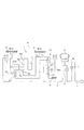
- the skeleton figure which shows the automatic transmission which concerns on this invention.
- the engagement table of this automatic transmission Sectional drawing which cut off the part containing the friction-plate lubrication apparatus which concerns on this invention in this automatic transmission.
- (A) is front sectional drawing which shows this friction board lubrication apparatus
- (B) is an enlarged view of the A section.
- a rotor 3 a of an electric motor 3 is connected to an input shaft 2 of the automatic transmission 1, and a clutch 6 and a torsion damper 7 are disposed between the shaft of the rotor 3 a and the engine output shaft 5.
- the automatic transmission 1 is applied as a one-motor type hybrid drive device H, and the electric motor 3 is used as a vehicle drive source and as a starter (cell motor) for driving the engine, and further, the engine power or the inertia of the vehicle. It functions as an alternator (generator) that converts force into electrical energy.
- the clutch 6 and the torsion damper 7 are arranged between the input shaft 2 and the engine output shaft 5, but this may be a torque converter with a lock-up clutch. In this case, the lock-up clutch Bears the function of the clutch 6.
- the input shaft 2 of the automatic transmission 1 is arranged coaxially with the electric motor 3, the clutch 6 and the engine output shaft 5, and on the input shaft 2, a planetary gear SP and a planetary gear unit PU are provided.
- the planetary gear SP is a so-called single pinion planetary gear that includes a sun gear S1, a carrier CR1, and a ring gear R1, and has a pinion P1 that meshes with the sun gear S1 and the ring gear R1.
- the planetary gear unit PU has a sun gear S2, a sun gear S3, a carrier CR2, and a ring gear R2 as four rotating elements.
- the carrier CR2 has a long pinion PL that meshes with the sun gear S2 and the ring gear R2, and the sun gear S3.
- This is a so-called Ravigneaux type planetary gear that has meshing short pinions PS that mesh with each other.
- the sun gear S1 of the planetary gear SP is connected to a boss (not shown) that is integrally fixed to the transmission case 9, and the rotation is fixed.
- the ring gear R1 is rotated in the same rotation as the input shaft 2 (hereinafter referred to as “input rotation”). Further, the carrier CR1 is decelerated by decelerating the input rotation by the fixed sun gear S1 and the input rotating ring gear R1, and is connected to the clutch C-1 and the clutch C-3.
- the sun gear S2 of the planetary gear unit PU is connected to the brake B-1 so as to be freely fixed to the transmission case 9, and is connected to the clutch C-3 via the clutch C-3.
- the deceleration rotation of CR1 can be freely input.
- the sun gear S3 is connected to the clutch C-1, so that the decelerated rotation of the carrier CR1 can be input.
- the carrier CR2 is connected to a clutch C-2 to which the rotation of the input shaft 2 is input, and the input rotation is freely input via the clutch C-2, and a brake (friction engagement element) is provided. ) Connected to B-2, the rotation can be fixed via the brake B-2.
- the ring gear R2 is connected to a counter gear 11, and the counter gear 11 is connected to a drive wheel via a counter shaft and a differential device (not shown).
- the clutches C-1 to C-3 and the brakes B-1 and B-2 shown in the skeleton of FIG. 1 are engaged and disengaged with the combinations shown in the engagement table of FIG.
- the first forward speed (1st) to the sixth forward speed (6th) and the first reverse speed (Rev) are achieved.
- the brake B-2 is a brake that operates at the first speed and reverse, engages at the time of start, and performs slip control when the engine is started by the electric motor 3. That is, the vehicle enters the first speed state by engaging the clutch C-1 and engaging the brake B-2. In the first speed state, the rotation of the input shaft 2 is decelerated and transmitted to the sun gear S3 of the planetary gear unit PU by the engagement of the clutch C-1, and the carrier CR2 is stopped by the brake B-2. Thus, the speed is further reduced and output from the ring gear R2 to the counter gear 11.
- the clutch 6 is normally disengaged and the engine is stopped, and is driven by the electric motor 3.
- the engine (the output shaft 5 is shown) is started in the first speed state after the vehicle starts.
- slip control of the brake B-2 causes the carrier CR2 to rotate and absorbs the rotational difference between the sun gear S3 and the ring gear R2.
- the brake B-2 slip control absorbs the rotational difference between the input and output shafts, increases the torque of the electric motor 3 and connects the clutch 6 to start the engine.
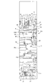
- FIG. 3 is a diagram showing the brake B-2 portion controlled by the slip.
- the brake (friction engagement element) B-2 having the multi-plate friction plates 12 and 16 is engaged with the inner spline 9a of the case 9.
- the outer friction plate (brake plate) 12 having teeth to be engaged on the outer periphery and the inner friction plate (brake disc) 16 having teeth engaging with the splines 15 of the hub 13 on the inner periphery are alternately arranged in the axial direction.
- An end plate 12a secured by a snap ring 19 is disposed at the tip of the outer friction plate 12, and a pressure plate 12b is disposed on the hydraulic piston side.
- the hub 13 is integrally fixed to the case 20 of the carrier CR2 by welding or the like, and the pinions PL and PS of the carrier CR2 are disposed in the case 20, and the ring gear R2 and the sun gear S2 are disposed on the pinion. , S3 are engaged.
- a sleeve 21 is integrally fixed to the carrier case 20 with a predetermined gap a inside the hub 13, and the hub 13 and the sleeve 21 are closed at the fixed end. Has been.
- the hub 13 and the sleeve 21 are made of a cylindrical member arranged coaxially, and extend in the axial direction with the hub 13 on the outer peripheral side and the sleeve 21 on the inner peripheral side, and the tip 21a of the sleeve 21 is the hub. 13 protrudes longer than the tip 13a by a predetermined length b, and is slightly bent in the outer diameter direction.
- the nozzle 25 for injecting the lubricating oil directs the lubricating oil into the gap “a” between the hub 13 and the sleeve 21 with the injection port 25 a directed to the space A having the predetermined length b. It arrange
- the carrier CR2, the ring gear R2, and the sun gears S2 and S3 constituting the planetary gear unit PU are arranged on the inner diameter side of the sleeve 21, and the planetary gear unit PU is formed on the input shaft 2, the long pinion shaft 40, and the like.
- the lubricating oil from the lubricating oil passages 36a and 36b is lubricated.
- the hub 13 is formed as a spline 15 whose splines 15 are formed by a press die having a predetermined plate thickness t, and the unevenness thereof is engaged with the teeth of the inner friction plate 16 on the outer periphery.
- a similar uneven portion 26 is formed on the inner peripheral surface over the entire circumference and in the axial direction.
- a large number of small holes (through holes) 27 are formed through the bottom surface of the concave portion 26a of the concave and convex portion 26 at predetermined intervals in the axial direction. As shown in FIG.
- the lubricating oil O is stored in the oil reservoir 26a, and the lubricating oil O in the oil reservoir 26a is supplied to the multi-plate friction plates 12 and 16 of the brake B-2 through the small hole 27. Further, as shown in FIG. 3, the tip end 13a of the hub is bent so that the end of the concave portion 26a serving as the oil reservoir is covered to form an annular flange.
- One nozzle 25 is provided at a predetermined angular position ⁇ , for example, 100 ° to 120 ° in the normal rotation direction of the hub 13 (direction rotating when the vehicle moves forward) with respect to the diameter (vertical) line vv in the vertical direction. It is preferably disposed in the range of 105 ° to 112 °.
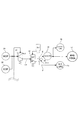
- the hydraulic circuit includes a mechanical oil pump 29 and an electric oil pump 30 that are driven in conjunction with the input shaft (or engine output shaft) 2 of the automatic transmission 1. Is adjusted to the lubricating oil pressure LP by the regulator valve 31 controlled by the electric signal SUC from the controller.
- the lubricating oil pressure LP is switched between an oil path E to the oil cooler 35 and a lubricating oil path F for the brake B-2 guided to the nozzle 25 by a valve 32 that is switched by a solenoid valve So1.
- the solenoid valve So1 When the solenoid valve So1 is OFF, the switching valve 32 is connected from the oil passage E to the lubricating oil passage 36 for the gear train and the electric motor 3 through the oil cooler 35 and to the lubricating passage 37.
- Lubricating oil is supplied and when the solenoid valve So1 is ON, the lubricating oil is supplied to the brake B-2 lubricating nozzle 25 via the brake B-2 lubricating oil passage F.
- the solenoid valve So1 is turned on in conjunction with an electrical signal indicating that the controller performs slip control on the brake B-2, for example, energization of an ignition coil for starting the engine, and a signal indicating that the clutch 6 is connected. Is done.
- the oil passage E to the oil cooler and the lubricating oil passage F for the brake B-2 communicate with each other through an orifice 39.
- the friction plate lubrication device Since the friction plate lubrication device has the above-described configuration, hydraulic pressure is generated by the mechanical oil pump 29 when the vehicle is running, and hydraulic pressure is generated by the electric oil pump 30 when the vehicle is stopped, and the regulator valve 31.
- the lubricating oil pressure adjusted in this way circulates through the oil cooler 35 through the oil passage E, lubricates the automatic transmission 1 (36), and cools the electric motor 3 (37). At this time, a small amount of lubricating oil is also supplied to the brake B-2 via the orifice 39.
- a predetermined low pressure is supplied to the brake B-2, slip control is performed, the clutch 6 is engaged, and the engine is started by the electric motor 3. .
- the electric motor 3 outputs a predetermined torque and number of revolutions, starts the engine smoothly while slipping the clutch 6, and controls the brake B-2 to absorb the rotational difference between the input and output shafts. A smooth torque with little start shock is output to the output unit 11.
- the solenoid valve So1 is turned on in accordance with the timing at which the brake B-2 needs slip control, and the lubricating oil pressure LP is supplied to the lubricating oil passage F for the brake B-2.
- the lubricating oil in the oil passage F is discharged from the injection port 25a of the nozzle 25 into the space A and is supplied to the relatively narrow gap a between the hub 13 and the sleeve 21 with little leakage.
- the lubricating oil supplied from the nozzle injection port 25a at a predetermined angular position ⁇ in FIG. 4A is uneven on the inner peripheral surface of the hub 13 due to gravity and centrifugal force generated by the rotation of the hub 13 and the sleeve 21 based on slip control.
- the hole diameter of the small hole 27 is set so that the lubricating oil in each oil reservoir 26a disappears when the hub 13 makes one rotation in the slip control. Therefore, the multi-plate friction plates 12 and 16 of the brake B-2 are supplied with a substantially uniform and sufficient amount of lubricating oil over the entire circumference and over the entire length in the axial direction. Even if slip control frequently occurs and it takes a relatively long time, the durability of the multi-plate friction plates 12 and 16 is not affected, and the slip control is performed without any problem.
- the recess 26a serving as the oil reservoir has its tip 13a covered, and the lubricating oil O stored in the recess 26a is not scattered from the tip by centrifugal force or the like, and the lubricant is wasted. Without being changed, it is supplied to the multi-plate friction plates 12 and 16 of the brake B-2 with high efficiency. Further, even if the rotational speed of the hub 13 is low and sufficient centrifugal force does not act on the lubricating oil O, the lubricating oil diffused in the relatively narrow gap a is less likely to leak outward from the space A, and is small.
- the holes 27 are supplied to the multi-plate friction plates 12 and 16 of the brake B-2.
- the switching valve 32 is switched to the brake B-2 lubricating oil passage F, and lubricates the gear train lubricating oil passage 36 via the oil passage E.
- the lubricating oil passage 36 for gear train is supplied with sufficient lubricating oil before that, and even during the slip control, the lubricating oil passage shown in FIG.
- the lubricating oil supplied from 36a, 36b to the planetary gear unit PU is continuously scattered from the radial oil passage by the centrifugal force.
- Lubricating oil whose flow rate varies depending on the rotational speed of the rotary shafts 2 and 40 is blocked by the sleeve 21 disposed so as to cover the outer diameter side of the planetary gear unit PU, and between the sleeve 21 and the hub 13. It is not supplied to the oil sump 26a. Accordingly, only the lubricating oil from the nozzle 25 via the oil passage F is supplied to the brake B-2, and the multi-plate friction plates 12 and 16 of the brake B-2 Slip control is performed by supplying an appropriate amount of lubricating oil evenly distributed over the entire length.
- the slip control of the brake B-2 at the time of starting the engine has been described.
- the friction plate lubrication device operates in the same manner when the electric motor 3 is rotated and charged by the engine. May be.
- the brake B-2 is set to the first speed state and the brake B-2 is prepared for starting with the slip control (having torque) or the standby pressure state.
- a sufficient amount of lubricating oil is supplied from the nozzle 25.
- the brake B-2 is slipped to absorb the rotational difference between the input and output shafts.
- the sleeve 21 is arranged on the inner peripheral side of the hub 13 so as to prevent the lubricating oil from splashing and reliably supply it to the friction plate.
- the friction plate lubricating device is not limited to the automatic transmission device of the hybrid drive device.
- the friction plate lubrication device is in a fine engagement state in an automatic transmission device using only the engine as a drive source. Is equally applicable.
- the automatic transmission according to the present invention is suitable for use in an automobile, in particular, a hybrid drive device using an engine and an electric motor as drive sources.
- the engine is started by a multi-plate friction plate such as a brake of the automatic transmission, particularly an electric motor.
- This is used in a lubrication apparatus for lubricating a multi-plate friction plate of a friction engagement element that is slip-controlled.
Landscapes
- Engineering & Computer Science (AREA)
- General Engineering & Computer Science (AREA)
- Mechanical Engineering (AREA)
- General Details Of Gearings (AREA)
- Hydraulic Clutches, Magnetic Clutches, Fluid Clutches, And Fluid Joints (AREA)
Abstract
スリップ制御又は微係合時、多板摩擦板に潤滑油を均等に供給する。内摩擦板の内歯を係合するスプライン(15)を有するハブ(13)は、内周にも同様な凹凸部(26)が形成される。ハブ(13)の内周側にスリーブ(21)を配置し、ハブとスリーブとの間の隙間(a)にノズル(25)から潤滑油を供給する。潤滑油(O)は、凹凸部の凹部(26a)内に溜められ、底面に軸方向に亘って複数個形成された貫通孔(27)から、多板摩擦板の全周及び全長に亘って均等に供給される。
Description
本発明は、自動変速装置、特にエンジンと電気モータを駆動源とするハイブリッド駆動装置に用いられる自動変速装置に適用して好適であり、詳しくは該自動変速装置のブレーキ等の摩擦係合要素における多板摩擦板に潤滑油を供給する摩擦板潤滑装置に関する。
従来、自動変速装置において、クラッチ又はブレーキ(摩擦係合要素)に用いられる湿式多板摩擦板に噴射口(ノズル)から潤滑油を直接供給する摩擦板潤滑装置が案出されている(例えば特許文献1参照)。特許文献1のものは、カウンタドライブギヤを挟んで、上記多板摩擦板(多板クラッチの摩擦板)の反対側に潤滑油の噴射口が配置されている。ドライブレンジが選択されてエンジンがアイドル状態にある車輌の停車中に、自動変速装置の少なくとも1個の摩擦係合要素(例えばフォワードクラッチ)を滑らせること(微係合状態)で入出力軸間の回転差を吸収することが好ましいが、車輌停車中はカウンタドライブギヤが停止しているので、該ドライブギヤの貫通孔を通して、噴射口から多板摩擦板に充分な潤滑油が供給され、車輌の走行時は回転するカウンタドライブギヤにより上記噴射口からの潤滑油の供給が妨げられる。
前記特許文献1記載の摩擦板潤滑装置は、噴射口からカウンタドライブギヤの貫通孔を介して、潤滑油が多板摩擦板の最外側のリテーニング(エンド)プレート部分に供給されるため、潤滑油を多板摩擦板に均等に供給することは困難であり、特に噴射口から離れた多板摩擦板の奥側には充分に潤滑油が行き渡り難い。
駆動源としてエンジンの外に1個の電気モータを備え、該駆動源から自動変速装置を介して駆動車輪に伝達するハイブリッド駆動装置にあっては、電気モータの駆動により発進し、必要に応じて電気モータのトルクによりエンジンを始動する。この際、エンジンの始動には電気モータのトルクを上昇する必要があるが、その際のトルク変動を車輪へ伝達するのを防止するために自動変速装置の所定の摩擦係合要素を滑らすことにより、上記トルク変動を吸収することが好ましい。このようなハイブリッド駆動装置にあっては、エンジン始動に際して上記所定の摩擦係合要素を滑らす制御は、度々かつ比較的長い時間行う必要があり、上述した噴射口を多板摩擦板の最外側に向いて噴射する摩擦板潤滑装置を適用しても、多板摩擦板に均等に、特にその全長及び全周に亘って充分な潤滑油を供給することができず、摩擦板の耐久性に影響を及ぼす虞がある。
そこで、本発明は、多板摩擦板に、均等に潤滑油を供給することを可能とし、もって上述した課題を解決した自動変速装置の摩擦板潤滑装置を提供することを目的とするものである。
本発明は、外摩擦板(12)と内摩擦板(16)とを交互に配置した多板摩擦板を有する摩擦係合要素(B-2)と、前記内摩擦板(16)の内周に形成された歯に係合するスプライン(15)を有するハブ(13)と、を備えた自動変速装置(1)の摩擦板潤滑装置において、
前記ハブ(13)は、外周に前記スプライン(15)を形成すると共に内周に凹凸部(26)を形成し、
該凹凸部に向けて潤滑油を吐出するノズル(25)を備え、
前記凹凸部(26)の各凹部(26a)を、前記潤滑油が溜まる油溜りとすると共に、該凹部の底面に貫通孔(27)を形成し、
前記ノズル(25)からの潤滑油を、前記凹部(26a)からなる油溜りに溜めて、前記貫通孔(27)を通して前記摩擦係合要素(B-2)の多板摩擦板(12,16)に供給してなる、
自動変速装置の摩擦板潤滑装置にある。
前記ハブ(13)は、外周に前記スプライン(15)を形成すると共に内周に凹凸部(26)を形成し、
該凹凸部に向けて潤滑油を吐出するノズル(25)を備え、
前記凹凸部(26)の各凹部(26a)を、前記潤滑油が溜まる油溜りとすると共に、該凹部の底面に貫通孔(27)を形成し、
前記ノズル(25)からの潤滑油を、前記凹部(26a)からなる油溜りに溜めて、前記貫通孔(27)を通して前記摩擦係合要素(B-2)の多板摩擦板(12,16)に供給してなる、
自動変速装置の摩擦板潤滑装置にある。
例えば図3及び図4を参照して、前記貫通孔(27)は、前記凹凸部(26)の各凹部(26a)の底面にそれぞれかつ軸方向に複数個配置され、
潤滑油が、前記貫通孔(27)を通して前記多板摩擦板(12,16)の全周に亘ってかつ軸方向全長に亘って供給されてなる。
潤滑油が、前記貫通孔(27)を通して前記多板摩擦板(12,16)の全周に亘ってかつ軸方向全長に亘って供給されてなる。
例えば図3及び図4を参照して、前記ハブ(13)の内周側に、所定隙間(a)を存して、該ハブ(13)と一体にスリーブ(21)を配置し、
前記ノズル(25)から、前記ハブ(13)とスリーブ(21)との間の前記所定隙間(a)に潤滑油を供給してなる。
前記ノズル(25)から、前記ハブ(13)とスリーブ(21)との間の前記所定隙間(a)に潤滑油を供給してなる。
例えば図3を参照して、前記スリーブ(21)の内径側に、プラネタリギヤ(PU)が配置され、
該プラネタリギヤ(PU)は、軸(2,40)に形成された潤滑油路(36a,36b)からの潤滑油により潤滑されてなる。
該プラネタリギヤ(PU)は、軸(2,40)に形成された潤滑油路(36a,36b)からの潤滑油により潤滑されてなる。
例えば図3を参照して、前記ハブ(13)とスリーブ(21)は、一端を一体に固定して前記所定隙間(a)が閉塞されると共に、他端を、前記スリーブ(21)が前記ハブ(13)に対して所定長さ(b)突出し、
前記所定長さ突出した前記スリーブ(21)の外径側の空間(A)に向けて潤滑油が噴射されるように前記ノズル(25)を配置してなる。
前記所定長さ突出した前記スリーブ(21)の外径側の空間(A)に向けて潤滑油が噴射されるように前記ノズル(25)を配置してなる。
例えば、図1,図2及び図5を参照して、前記自動変速装置(1)の入力軸(2)のエンジン出力軸(5)側に、電気モータ(3)及びクラッチ(6)を配置し、
前記摩擦係合要素が、前記自動変速装置の少なくとも1速時に係合するブレーキ(B-2)であり、
前記電気モータ(3)によりエンジンを始動する際、前記ブレーキ(B-2)をスリップ制御して前記自動変速装置の入出力部の回転差を吸収し、
前記ブレーキ(B-2)のスリップ制御にタイミングを合せて前記ノズル(25)から潤滑油を吐出してなる。
前記摩擦係合要素が、前記自動変速装置の少なくとも1速時に係合するブレーキ(B-2)であり、
前記電気モータ(3)によりエンジンを始動する際、前記ブレーキ(B-2)をスリップ制御して前記自動変速装置の入出力部の回転差を吸収し、
前記ブレーキ(B-2)のスリップ制御にタイミングを合せて前記ノズル(25)から潤滑油を吐出してなる。
なお、上記カッコ内の符号は、図面と対照するためのものであるが、これにより特許請求の範囲に記載の構成に何等影響を及ぼすものではない。
請求項1に係る本発明によると、ハブの外周にスプラインを形成すると共に内周にも凹凸部を形成して、ノズルから該凹凸部に潤滑油を供給して上記凹凸部の凹部を油溜りとし、上記凹部の底面に形成した貫通孔を介して、摩擦係合要素の多板摩擦板に潤滑油を供給するので、多板摩擦板は、略々均等に潤滑油が供給されて、例えばスリップ制御及び微係合時においても上記多板摩擦板の耐久性を確保して、正確な制御を行うことができ、かつ必要時にのみ適切に多板摩擦板に潤滑油を供給することを可能にして、引き摺りトルク低減を図ることができる。
請求項2に係る本発明によると、貫通孔は、凹凸部の各凹部の底面にそれぞれかつ軸方向に複数個配置されるので、潤滑油が、多板摩擦板の全周に亘ってかつ軸方向全長に亘って略々均等に供給することができる。
請求項3に係る本発明によると、ハブの内周側にスリーブを配置して、ハブとスリーブとの間の所定隙間に向けてノズルから潤滑油を供給するので、潤滑油は、例えばハブが低回転で遠心力が充分に作用しない場合でも、凹部からなる油溜りに保持されて、確実に多板摩擦板に供給される。
請求項4に係る本発明によると、スリーブの内径側には、軸に形成された潤滑油路からの潤滑油により潤滑されるプラネタリギヤが配置されており、該プラネタリギヤからの潤滑油が、その外径側にある前記多板摩擦板に向けて飛散されることになり、かつ該プラネタリギヤからの潤滑油は、軸の回転数等によりその供給量が変化するが、該飛散された潤滑油が上記多板摩擦板にかかることが、上記スリーブにより阻止される。従って、例えばスリップ制御及び微係合時等にあって高い精度で滑りを管理する必要がある多板摩擦板にあっても、上記プラネタリギヤからの流量が変化する潤滑油の供給が阻止され、ノズルからの潤滑油が、安定した高い信頼性により上記多板摩擦板に供給される。
請求項5に係る本発明によると、スリーブの先端をハブの先端より長く突出して、該突出したスリーブの外径側の空間に向けてノズルから潤滑油が噴射されるので、ノズルからの潤滑油は、外に漏れることなく略々確実に比較的狭い所定隙間に供給することができ、潤滑油を無駄にすることなく高い効率で多板摩擦板に潤滑油を供給することができる。
請求項6に係る本発明によると、自動変速装置と電気モータとを有するハイブリッド駆動装置に適用して、電気モータでエンジンを始動する際、1速で係合するブレーキをスリップ制御して入出力部の回転差を吸収すると共に、該スリップ制御を行うブレーキの多板摩擦板に均等に潤滑油を供給して、エンジン始動を確実かつ正確に行うことができると共に、始動時のショックを減少することができる。また、上記ブレーキへの潤滑油の供給は、スリップ制御にタイミングを合せて行うので、該ブレーキへの潤滑油の供給は、必要時にのみ行われて、潤滑油の無駄がなく、燃費性能を向上することができる。
以下、図面に沿って、本発明の実施の形態について説明する。図1に示すように、自動変速装置1の入力軸2には電気モータ3のロータ3aが連結されており、該ロータ3aの軸とエンジン出力軸5との間にはクラッチ6及びトーションダンパ7が介在している。従って、本自動変速装置1は、1モータタイプのハイブリッド駆動装置Hとして適用され、上記電気モータ3は、車輌駆動源として、またエンジンを駆動するスタータ(セルモータ)として、更にエンジン動力又は車輌の慣性力を電気エネルギに変換するオルタネータ(ジェネレータ)として機能する。なお、入力軸2とエンジン出力軸5との間に、上記クラッチ6及びトーションダンパ7を配置しているが、これは、ロックアップクラッチ付のトルクコンバータでもよく、この場合、該ロックアップのクラッチが上記クラッチ6の機能を担う。
自動変速装置1の上記入力軸2は、電気モータ3,クラッチ6及びエンジン出力軸5と同軸上に配置され、該入力軸2上において、プラネタリギヤSPと、プラネタリギヤユニットPUとが備えられている。上記プラネタリギヤSPは、サンギヤS1、キャリヤCR1、及びリングギヤR1を備えており、該キャリヤCR1に、サンギヤS1及びリングギヤR1に噛合するピニオンP1を有している、いわゆるシングルピニオンプラネタリギヤである。
また、該プラネタリギヤユニットPUは、4つの回転要素としてサンギヤS2、サンギヤS3、キャリヤCR2、及びリングギヤR2を有し、該キャリヤCR2に、サンギヤS2及びリングギヤR2に噛合するロングピニオンPLと、サンギヤS3に噛合するショートピニオンPSとを互いに噛合する形で有している、いわゆるラビニヨ型プラネタリギヤである。
上記プラネタリギヤSPのサンギヤS1は、ミッションケース9に一体的に固定されている不図示のボス部に接続されて回転が固定されている。また、上記リングギヤR1は、上記入力軸2の回転と同回転(以下「入力回転」という。)になっている。さらに、上記キャリヤCR1は、上記固定されたサンギヤS1と該入力回転するリングギヤR1とにより、入力回転が減速された減速回転になるとともに、クラッチC-1及びクラッチC-3に接続されている。
上記プラネタリギヤユニットPUのサンギヤS2は、ブレーキB-1に接続されてミッションケース9に対して固定自在となっているとともに、上記クラッチC-3に接続され、該クラッチC-3を介して上記キャリヤCR1の減速回転が入力自在となっている。また、上記サンギヤS3は、クラッチC-1に接続されており、上記キャリヤCR1の減速回転が入力自在となっている。
さらに、上記キャリヤCR2は、入力軸2の回転が入力されるクラッチC-2に接続され、該クラッチC-2を介して入力回転が入力自在となっており、また、ブレーキ(摩擦係合要素)B-2に接続されて、該ブレーキB-2を介して回転が固定自在となっている。そして、上記リングギヤR2は、カウンタギヤ11に接続されており、該カウンタギヤ11は、不図示のカウンタシャフト、ディファレンシャル装置を介して駆動車輪に接続されている。
上記構成の自動変速装置1は、図1のスケルトンに示す各クラッチC-1~C-3、ブレーキB-1,B-2が、図2の係合表に示す組み合わせで係脱されることにより、前進1速段(1st)~前進6速段(6th)、及び後進1速段(Rev)を達成している。
前記ブレーキB-2は、1速及びリバース時に作動するブレーキであり、発進時に係合すると共に、電気モータ3によるエンジンの始動時にスリップ制御する。即ち、車輌は、クラッチC-1を係合すると共にブレーキB-2を係合することにより1速状態となる。該1速状態にあっては、クラッチC-1の係合により、入力軸2の回転が減速されてプラネタリギヤユニットPUのサンギヤS3に伝達され、ブレーキB-2によりキャリヤCR2が停止していることにより、更に減速されてリングギヤR2からカウンタギヤ11に出力される。該1速による車輌の発進時、通常、クラッチ6が切断されると共にエンジンは停止しており、電気モータ3により駆動される。
そして、該車輌発進後の上記1速状態でエンジン(出力軸5を図示)が始動される。この際、ブレーキB-2をスリップ制御することにより、キャリヤCR2を回転し、サンギヤS3及びリングギヤR2の回転差を吸収する。
上記ブレーキB-2のスリップ制御により、入出力軸間の回転差を吸収した状態で、電気モータ3のトルクを上げると共に、クラッチ6を繋いで、エンジンを始動する。
図3は、上記スリップ制御されるブレーキB-2部分を示す図であり、多板摩擦板12,16を有するブレーキ(摩擦係合要素)B-2は、ケース9の内スプライン9aに係合する歯を外周に有する外摩擦板(ブレーキプレート)12と、ハブ13のスプライン15に係合する歯を内周に有する内摩擦板(ブレーキディスク)16とが交互に軸方向に並んで配置されており、これら外摩擦板12の先端にスナップリング19で抜止めされたエンドプレート12aが配置されていると共に、油圧ピストン側にプレッシャプレート12bが配置されている。
ハブ13は、前記キャリヤCR2のケース20に溶接等により一体に固着されており、該ケース20内には前記キャリヤCR2のピニオンPL,PSが配置されていると共に、ピニオンにはリングギヤR2及びサンギヤS2,S3が噛合している。上記キャリヤケース20には、上記ハブ13の内側にて所定隙間aを隔ててスリーブ21が一体に固着されており、ハブ13及びスリーブ21は、該固定された一端にて上記所定隙間aが閉塞されている。従って、ハブ13とスリーブ21は、同軸状に配置された円筒部材からなり、ハブ13を外周側にしてかつスリーブ21を内周側にして軸方向に平行に延び、スリーブ21の先端21aはハブ13の先端13aより所定長さbだけ長く突出し、かつ僅かに外径方向に折曲している。そして、ケース9の所定位置には、潤滑油を噴射するノズル25が、その噴射口25aを上記所定長さbからなる空間Aに向けて、上記ハブ13とスリーブ21の隙間aに潤滑油を吐出するように配置されている。
即ち、スリーブ21の内径側には、前記プラネタリギヤユニットPUを構成するキャリヤCR2、リングギヤR2、サンギヤS2,S3が配置されており、該プラネタリギヤユニットPUは、入力軸2及びロングピニオン軸40等に形成された潤滑油路36a,36bからの潤滑油により潤滑される。
前記ハブ13は、図4(A)に示すように、そのスプライン15が所定板厚tのプレス型により成形され、その凹凸は、外周に内摩擦板16の歯と係合するスプライン15として形成されていると共に、内周面にも同様な凹凸部26が全周に亘ってかつ軸方向形成されている。該凹凸部26の凹部26aの底面にはそれぞれかつ軸方向に所定間隔で小孔(貫通孔)27が貫通して多数形成されており、図4(B)に示すように、上記凹部26aは潤滑油Oが溜る油溜りとなり、該油溜り26aの潤滑油Oが上記小孔27を通って、ブレーキB-2の多板摩擦板12,16に供給される。また、ハブの先端13aは、図3に示すように、上記油溜りとなる凹部26aの端が蓋されるように折曲して、円環状の鍔部となっている。
前記ノズル25は、所定角度位置αに1個、例えば上下方向の直径(垂直)線v-vに対してハブ13の正転方向(車輌の前進時に回転する方向)に100°~120°、好ましくは105°~112°の範囲に配置される。
油圧回路は、図5に示すように、自動変速装置1の入力軸(又はエンジン出力軸)2に連動して駆動される機械式オイルポンプ29と電動オイルポンプ30を有しており、これらポンプによる油圧は、コントローラからの電気信号SUCにより制御されるレギュレータバルブ31により潤滑油圧LPに調圧される。該潤滑油圧LPは、ソレノイドバルブSo1により切換えられるバルブ32によりオイルクーラ35への油路Eと上記ノズル25に導かれるブレーキB-2用潤滑油路Fとに切換えられる。該切換えバルブ32は、該ソレノイドバルブSo1のOFF時にあっては、油路Eからオイルクーラ35を介して自動変速装置1のギヤトレイン用潤滑油路36及び電気モータ3の冷却、潤滑路37へ潤滑油を供給し、ソレノイドバルブSo1のON時、上記ブレーキB-2用潤滑油路Fを介してブレーキB-2潤滑用ノズル25に潤滑油を供給する。上記ソレノイドバルブSo1は、コントローラが上記ブレーキB-2をスリップ制御を行う旨の電気信号、例えばエンジンを始動するためのイグニッションコイルへの通電、クラッチ6を接続する旨の信号に連動して、ONされる。また、上記オイルクーラへの油路EとブレーキB-2用潤滑油路Fとの間はオリフィス39を介して連通している。
本摩擦板潤滑装置は以上のような構成を有するので、車輌走行時は、機械式オイルポンプ29により油圧が発生し、また車輌停止時は、電動オイルポンプ30により油圧が発生し、レギュレータバルブ31により調圧された潤滑油圧が、油路Eを通ってオイルクーラ35を循環しつつ、自動変速装置1を潤滑(36)すると共に電気モータ3を冷却する(37)。なおこの際、ブレーキB-2にもオリフィス39を介して潤滑油が少量供給される。そして、自動変速装置1の1速においてエンジンを作動する際、ブレーキB-2に所定低圧が供給されて、スリップ制御すると共に、クラッチ6を係合して、電気モータ3によりエンジンが始動される。この際、電気モータ3は所定トルク及び回転数を出力し、クラッチ6をスリップしつつ滑らかにエンジンを始動すると共に、ブレーキB-2をスリップ制御して、入出力軸の回転差を吸収しかつ出力部11に始動ショックの少ない滑らかなトルクを出力する。
そして、上記ブレーキB-2がスリップ制御を必要とするタイミングに合せて、ソレノイドバルブSo1がONされて、潤滑油圧LPがブレーキB-2用潤滑油路Fに供給される。該油路Fの潤滑油は、ノズル25の噴射口25aから空間Aに吐出され、ハブ13とスリーブ21との比較的狭い隙間aに殆ど漏すことなく供給される。図4(A)に所定角度位置αにてノズル噴射口25aから供給される潤滑油は、重力とスリップ制御に基づくハブ13及びスリーブ21の回転による遠心力とにより、ハブ13内周面の凹凸部26の凹部26aからなる油溜りに入って軸方向に拡がり、更に上記遠心力により油溜り26a内に張り付いて、小孔27から徐々に多板摩擦板12,16に向って排出される。小孔27の孔径は、スリップ制御において略々ハブ13が1回転したときに各油溜り26aの潤滑油がなくなるように設定されている。従って、上記ブレーキB-2の多板摩擦板12,16は、その全周に亘ってかつ軸方向全長に亘って、略々均等にかつ充分な量の潤滑油が供給されて、該ブレーキのスリップ制御が度々生じ、かつ比較的長時間に亘っても、多板摩擦板12,16の耐久性には影響を与えることはなく、スリップ制御が支障なく行われる。
この際、上記油溜りとなる凹部26aは、その先端13aが蓋されており、凹部26aに溜められた潤滑油Oは、遠心力等により先端から飛散することはなく、潤滑油は、無駄になることなく高い効率でブレーキB-2の多板摩擦板12,16に供給される。また、例えハブ13の回転速度が低く、充分な遠心力が潤滑油Oに作用しなくても、比較的狭い隙間aに拡散した潤滑油は、空間Aから外方に漏れることは少なく、小孔27からブレーキB-2の多板摩擦板12,16に供給される。
また、上記ブレーキB-2のスリップ制御中にあっては、切換えバルブ32がブレーキB-2用潤滑油路Fに切換えられて、油路Eを介してギヤトレイン用潤滑油路36への潤滑油の供給は停止されているが、該ギヤトレイン用潤滑油路36へは、その前に充分な潤滑油が供給されており、上記スリップ制御中にあっても、図3に示す潤滑油路36a,36bからプラネタリギヤユニットPUに供給された潤滑油は、遠心力により径方向油路から外径方向飛散され続ける。該回転軸2,40の回転速度等により流量が変化する潤滑油はプラネタリギヤユニットPUの外径側を覆うように配置されているスリーブ21により阻止されて、上記スリーブ21とハブ13との間の油溜り26aに供給されることはない。従って、上記ブレーキB-2には、油路Fを経由したノズル25からの潤滑油のみが供給されることになり、該ブレーキB-2の多板摩擦板12,16は、その全周及び全長に亘って均等に行き渡った適正な量の潤滑油供給によりスリップ制御される。
エンジンの始動が完了すると、上記ブレーキB-2のスリップ制御が解除されると共に、上記ソレノイドバルブSo1はOFFとなり、ノズル25から大量の潤滑油による摩擦板潤滑は停止され、油路Eに充分な潤滑油が供給されると共に、オリフィス39を介して少量の潤滑油がブレーキB-2に供給される。従って、切換えバルブ32がブレーキB-2用潤滑油路Fに切換えられ、本摩擦板潤滑装置が作動する状態は、スリップ制御等の潤滑必要時に限られ、潤滑油が無駄になることはなく、燃費向上に役立っている。
なお、上記説明は、エンジン始動時のブレーキB-2のスリップ制御について説明したが、車輌停止時に、エンジンにより電気モータ3を回転して充電する際にも本摩擦板潤滑装置を同様に作動してもよい。即ち、車輌停止時、1速状態にしてブレーキB-2は、スリップ制御(トルクを有する)又は待機圧状態として発進に備えているが、この際も、ノズル25から充分な量の潤滑油を供給して、ブレーキB-2をスリップして、入出力軸の回転差を吸収する。
また、本実施の形態は、ハブ13の内周側にスリーブ21を配置して、潤滑油の飛散を防止して確実に摩擦板に供給するように構成してあるが、上述したエンジン始動時等のハブ13が回転している状態では、遠心力により油溜り26aに潤滑油が保持されるので、スリーブを備えないものでも適用可能である。また、本摩擦板潤滑装置は、ハイブリッド駆動装置の自動変速装置に限らず、例えば先行技術としての前記特許文献1に示すように、エンジンのみを駆動源とする自動変速装置における微係合状態にも同様に適用可能である。
本発明に係る自動変速装置は、自動車、特にエンジンと電気モータを駆動源とするハイブリッド駆動装置に用いて好適であり、該自動変速装置のブレーキ等の多板摩擦板、特に電気モータによりエンジン始動する際にスリップ制御される摩擦係合要素の多板摩擦板を潤滑する潤滑装置に利用される。
1 自動変速装置
2 (入力)軸
3 電気モータ
5 エンジン出力軸
6 クラッチ
B-2 摩擦係合要素(ブレーキ)
9 ケース
12 外摩擦板(多板摩擦板)
13 ハブ
15 スプライン
16 内摩擦板(多板摩擦板)
21 スリーブ
25 ノズル
26 凹凸部
26a 凹部(油溜り)
27 貫通孔(小孔)
36 ギヤトレイン用潤滑油路
36a,36b 潤滑油路
40 (ピニオン)軸
PU プラネタリギヤユニット
a 所定隙間
b 所定長さ
2 (入力)軸
3 電気モータ
5 エンジン出力軸
6 クラッチ
B-2 摩擦係合要素(ブレーキ)
9 ケース
12 外摩擦板(多板摩擦板)
13 ハブ
15 スプライン
16 内摩擦板(多板摩擦板)
21 スリーブ
25 ノズル
26 凹凸部
26a 凹部(油溜り)
27 貫通孔(小孔)
36 ギヤトレイン用潤滑油路
36a,36b 潤滑油路
40 (ピニオン)軸
PU プラネタリギヤユニット
a 所定隙間
b 所定長さ
Claims (6)
- 外摩擦板と内摩擦板とを交互に配置した多板摩擦板を有する摩擦係合要素と、前記内摩擦板の内周に形成された歯に係合するスプラインを有するハブと、を備えた自動変速装置の摩擦板潤滑装置において、
前記ハブは、外周に前記スプラインを形成すると共に内周に凹凸部を形成し、
該凹凸部に向けて潤滑油を吐出するノズルを備え、
前記凹凸部の各凹部を、前記潤滑油が溜まる油溜りとすると共に、該凹部の底面に貫通孔を形成し、
前記ノズルからの潤滑油を、前記凹部からなる油溜りに溜めて、前記貫通孔を通して前記摩擦係合要素の多板摩擦板に供給してなる、
自動変速装置の摩擦板潤滑装置。 - 前記貫通孔は、前記凹凸部の各凹部の底面にそれぞれかつ軸方向に複数個配置され、
潤滑油が、前記貫通孔を通して前記多板摩擦板の全周に亘ってかつ軸方向全長に亘って供給されてなる、
請求項1記載の自動変速装置の摩擦板潤滑装置。 - 前記ハブの内周側に、所定隙間を存して、該ハブと一体にスリーブを配置し、
前記ノズルから、前記ハブとスリーブとの間の前記所定隙間に潤滑油を供給してなる、
請求項1又は2記載の自動変速装置の摩擦板潤滑装置。 - 前記スリーブの内径側に、プラネタリギヤが配置され、
該プラネタリギヤは、軸に形成された潤滑油路からの潤滑油により潤滑されてなる、
請求項1ないし3のいずれか記載の自動変速装置の摩擦板潤滑装置。 - 前記ハブとスリーブは、一端を一体に固定して前記所定隙間が閉塞されると共に、他端を、前記スリーブが前記ハブに対して所定長さ突出し、
前記所定長さ突出した前記スリーブの外径側の空間に向けて潤滑油が噴射されるように前記ノズルを配置してなる、
請求項3又は4記載の自動変速装置の摩擦板潤滑装置。 - 前記自動変速装置の入力軸のエンジン出力軸側に、電気モータ及びクラッチを配置し、
前記摩擦係合要素が、前記自動変速装置の少なくとも1速時に係合するブレーキであり、
前記電気モータによりエンジンを始動する際、前記ブレーキをスリップ制御して前記自動変速装置の入出力部の回転差を吸収し、
前記ブレーキのスリップ制御にタイミングを合せて前記ノズルから潤滑油を吐出してなる、
請求項1ないし5のいずれか記載の自動変速装置の摩擦板潤滑装置。
Priority Applications (2)
| Application Number | Priority Date | Filing Date | Title |
|---|---|---|---|
| DE112012000267T DE112012000267T5 (de) | 2011-02-23 | 2012-01-23 | Reibungsplattenschmiervorrichtung für ein Automatikgetriebe |
| CN2012800042766A CN103270345A (zh) | 2011-02-23 | 2012-01-23 | 用于自动变速器的摩擦片润滑装置 |
Applications Claiming Priority (2)
| Application Number | Priority Date | Filing Date | Title |
|---|---|---|---|
| JP2011037170A JP5382030B2 (ja) | 2011-02-23 | 2011-02-23 | 自動変速装置の摩擦板潤滑装置 |
| JP2011-037170 | 2011-02-23 |
Publications (1)
| Publication Number | Publication Date |
|---|---|
| WO2012114806A1 true WO2012114806A1 (ja) | 2012-08-30 |
Family
ID=46651847
Family Applications (1)
| Application Number | Title | Priority Date | Filing Date |
|---|---|---|---|
| PCT/JP2012/051339 Ceased WO2012114806A1 (ja) | 2011-02-23 | 2012-01-23 | 自動変速装置の摩擦板潤滑装置 |
Country Status (5)
| Country | Link |
|---|---|
| US (1) | US8715125B2 (ja) |
| JP (1) | JP5382030B2 (ja) |
| CN (1) | CN103270345A (ja) |
| DE (1) | DE112012000267T5 (ja) |
| WO (1) | WO2012114806A1 (ja) |
Cited By (2)
| Publication number | Priority date | Publication date | Assignee | Title |
|---|---|---|---|---|
| JP2013174335A (ja) * | 2012-02-27 | 2013-09-05 | Aisin Aw Co Ltd | 車両用駆動装置 |
| DE102012010322A1 (de) * | 2012-05-21 | 2013-11-21 | Getrag Getriebe- Und Zahnradfabrik Hermann Hagenmeyer Gmbh & Cie Kg | Kühlanordnung und Kühlverfahren für KFZ-Antriebsstrang |
Families Citing this family (11)
| Publication number | Priority date | Publication date | Assignee | Title |
|---|---|---|---|---|
| CN104100657B (zh) * | 2013-04-11 | 2018-01-23 | 内蒙古欧意德发动机有限公司 | 齿毂、液力自动变速器及汽车 |
| JP6289239B2 (ja) * | 2014-04-17 | 2018-03-07 | ジヤトコ株式会社 | 車両用自動変速機の摩擦締結要素における潤滑構造 |
| JP6265152B2 (ja) | 2015-03-02 | 2018-01-24 | 日本精工株式会社 | グリース塗布方法及び塗布装置、並びに、ウォーム減速機の製造方法、電動式パワーステアリング装置の製造方法、自動車の製造方法及び産業機械の製造方法 |
| US9902263B2 (en) * | 2015-11-24 | 2018-02-27 | American Axle & Manufacturing, Inc. | Multi-plate friction clutch having center lubricant feed and lubricant evacuation capabilities |
| DE102017203541B3 (de) * | 2017-03-03 | 2018-06-21 | Audi Ag | Antriebsvorrichtung und Kraftfahrzeug mit einer Antriebsvorrichtung |
| JP6274342B1 (ja) * | 2017-04-20 | 2018-02-07 | トヨタ自動車株式会社 | 変速機 |
| CN107289118B (zh) * | 2017-06-20 | 2021-08-27 | 中国北方车辆研究所 | 用于制动器内毂的行星排齿圈润滑结构和润滑方法 |
| JP6384585B1 (ja) * | 2017-12-13 | 2018-09-05 | トヨタ自動車株式会社 | 変速機 |
| JP2019129608A (ja) * | 2018-01-24 | 2019-08-01 | トヨタ自動車株式会社 | 車両用駆動装置 |
| JP7070346B2 (ja) | 2018-11-06 | 2022-05-18 | トヨタ自動車株式会社 | 自動変速機 |
| CN111230010B (zh) * | 2020-01-17 | 2020-09-08 | 荣成华东锻压机床股份有限公司 | 一种机械压力机制动器润滑系统 |
Citations (5)
| Publication number | Priority date | Publication date | Assignee | Title |
|---|---|---|---|---|
| JPS4517480Y1 (ja) * | 1965-04-26 | 1970-07-17 | ||
| JPH08247264A (ja) * | 1995-03-07 | 1996-09-24 | Koyo Seiko Co Ltd | 一方向クラッチの潤滑装置 |
| JP2002031217A (ja) * | 2000-07-12 | 2002-01-31 | Dainatsukusu:Kk | 湿式摩擦係合装置の冷却構造 |
| JP2007056909A (ja) * | 2005-08-22 | 2007-03-08 | Mazda Motor Corp | 変速機のクラッチの潤滑構造 |
| JP2010117006A (ja) * | 2008-11-14 | 2010-05-27 | Toyota Motor Corp | 筒状体およびそれを用いる摩擦係合装置 |
Family Cites Families (7)
| Publication number | Priority date | Publication date | Assignee | Title |
|---|---|---|---|---|
| US2913932A (en) * | 1955-10-04 | 1959-11-24 | Mcculloch Motors Corp | Variable speed planetary type drive |
| US4630494A (en) * | 1985-02-26 | 1986-12-23 | Kemper Yves J | Radially oriented nutational traction drive transmission |
| JP2000145819A (ja) * | 1998-11-06 | 2000-05-26 | Nsk Warner Kk | 湿式多板クラッチ |
| EP1610017A1 (de) * | 2004-06-21 | 2005-12-28 | LuK Lamellen und Kupplungsbau Beteiligungs KG | Drehmomentübertragungseinrichtung und Antriebstrang mit dieser |
| DE102005007686A1 (de) * | 2005-02-19 | 2006-08-31 | Zf Friedrichshafen Ag | Kühlölzuführung für ein nasslaufendes Schalt-bzw. Anfahrelement |
| JP4588651B2 (ja) * | 2006-02-24 | 2010-12-01 | トヨタ自動車株式会社 | 摩擦係合装置 |
| WO2009008192A1 (ja) * | 2007-07-06 | 2009-01-15 | Aisin Aw Co., Ltd. | 自動変速機の潤滑油供給装置 |
-
2011
- 2011-02-23 JP JP2011037170A patent/JP5382030B2/ja not_active Expired - Fee Related
-
2012
- 2012-01-19 US US13/353,945 patent/US8715125B2/en not_active Expired - Fee Related
- 2012-01-23 DE DE112012000267T patent/DE112012000267T5/de not_active Ceased
- 2012-01-23 CN CN2012800042766A patent/CN103270345A/zh active Pending
- 2012-01-23 WO PCT/JP2012/051339 patent/WO2012114806A1/ja not_active Ceased
Patent Citations (5)
| Publication number | Priority date | Publication date | Assignee | Title |
|---|---|---|---|---|
| JPS4517480Y1 (ja) * | 1965-04-26 | 1970-07-17 | ||
| JPH08247264A (ja) * | 1995-03-07 | 1996-09-24 | Koyo Seiko Co Ltd | 一方向クラッチの潤滑装置 |
| JP2002031217A (ja) * | 2000-07-12 | 2002-01-31 | Dainatsukusu:Kk | 湿式摩擦係合装置の冷却構造 |
| JP2007056909A (ja) * | 2005-08-22 | 2007-03-08 | Mazda Motor Corp | 変速機のクラッチの潤滑構造 |
| JP2010117006A (ja) * | 2008-11-14 | 2010-05-27 | Toyota Motor Corp | 筒状体およびそれを用いる摩擦係合装置 |
Cited By (3)
| Publication number | Priority date | Publication date | Assignee | Title |
|---|---|---|---|---|
| JP2013174335A (ja) * | 2012-02-27 | 2013-09-05 | Aisin Aw Co Ltd | 車両用駆動装置 |
| WO2013129455A1 (ja) * | 2012-02-27 | 2013-09-06 | アイシン・エィ・ダブリュ株式会社 | 車両用駆動装置 |
| DE102012010322A1 (de) * | 2012-05-21 | 2013-11-21 | Getrag Getriebe- Und Zahnradfabrik Hermann Hagenmeyer Gmbh & Cie Kg | Kühlanordnung und Kühlverfahren für KFZ-Antriebsstrang |
Also Published As
| Publication number | Publication date |
|---|---|
| DE112012000267T5 (de) | 2013-09-19 |
| JP2012172798A (ja) | 2012-09-10 |
| US20120211322A1 (en) | 2012-08-23 |
| JP5382030B2 (ja) | 2014-01-08 |
| US8715125B2 (en) | 2014-05-06 |
| CN103270345A (zh) | 2013-08-28 |
Similar Documents
| Publication | Publication Date | Title |
|---|---|---|
| JP5382030B2 (ja) | 自動変速装置の摩擦板潤滑装置 | |
| WO2012132723A1 (ja) | ハイブリッド駆動装置 | |
| JP5557044B2 (ja) | ハイブリッド駆動装置 | |
| JP2012180867A (ja) | 自動変速装置の潤滑装置 | |
| JP5297352B2 (ja) | 車両用駆動装置 | |
| US7025704B2 (en) | Planetary gear for automatic transmission | |
| JP2006266305A (ja) | プラネタリギヤの潤滑装置 | |
| JP2004508502A (ja) | 油圧クラッチと遊星歯車装置とを備え、特に自動変速機のための、特定的には自動車用自動変速機のための組込みアッセンブリ、及び当該アッセンブリを使用する自動変速機 | |
| WO2012118072A1 (ja) | ハイブリッド駆動装置 | |
| CN101248303B (zh) | 自动变速器的润滑装置 | |
| JP4770331B2 (ja) | 変速機のクラッチの潤滑構造 | |
| US9765882B2 (en) | Hydraulic control device of automatic transmission | |
| US20080105513A1 (en) | Starting clutch | |
| JP5261461B2 (ja) | 車両用駆動装置 | |
| CN101248293B (zh) | 自动变速器中的压力油供给装置 | |
| US20210148416A1 (en) | Power transmission device | |
| JP4585087B2 (ja) | 自動変速装置 | |
| JP6015401B2 (ja) | 自動変速機 | |
| KR101836826B1 (ko) | 자동 변속장치 | |
| JP3036911B2 (ja) | 自動変速機の強制潤滑装置 | |
| JP2013096533A (ja) | 自動変速機の油圧制御装置 | |
| JP2019157938A (ja) | 摩擦係合装置の潤滑装置 | |
| CN116336162A (zh) | 车辆用驱动装置 | |
| JP2023095761A (ja) | 車両用駆動装置 | |
| JP2017180757A (ja) | 自動変速機 |
Legal Events
| Date | Code | Title | Description |
|---|---|---|---|
| 121 | Ep: the epo has been informed by wipo that ep was designated in this application |
Ref document number: 12750258 Country of ref document: EP Kind code of ref document: A1 |
|
| WWE | Wipo information: entry into national phase |
Ref document number: 112012000267 Country of ref document: DE Ref document number: 1120120002679 Country of ref document: DE |
|
| 122 | Ep: pct application non-entry in european phase |
Ref document number: 12750258 Country of ref document: EP Kind code of ref document: A1 |