WO2012114611A1 - クリーニングガス及びそれを用いたリモートプラズマクリーニング方法 - Google Patents
クリーニングガス及びそれを用いたリモートプラズマクリーニング方法 Download PDFInfo
- Publication number
- WO2012114611A1 WO2012114611A1 PCT/JP2011/078855 JP2011078855W WO2012114611A1 WO 2012114611 A1 WO2012114611 A1 WO 2012114611A1 JP 2011078855 W JP2011078855 W JP 2011078855W WO 2012114611 A1 WO2012114611 A1 WO 2012114611A1
- Authority
- WO
- WIPO (PCT)
- Prior art keywords
- cleaning
- gas
- cleaning gas
- remote plasma
- reaction chamber
- Prior art date
- Legal status (The legal status is an assumption and is not a legal conclusion. Google has not performed a legal analysis and makes no representation as to the accuracy of the status listed.)
- Ceased
Links
Images


Classifications
-
- C—CHEMISTRY; METALLURGY
- C23—COATING METALLIC MATERIAL; COATING MATERIAL WITH METALLIC MATERIAL; CHEMICAL SURFACE TREATMENT; DIFFUSION TREATMENT OF METALLIC MATERIAL; COATING BY VACUUM EVAPORATION, BY SPUTTERING, BY ION IMPLANTATION OR BY CHEMICAL VAPOUR DEPOSITION, IN GENERAL; INHIBITING CORROSION OF METALLIC MATERIAL OR INCRUSTATION IN GENERAL
- C23C—COATING METALLIC MATERIAL; COATING MATERIAL WITH METALLIC MATERIAL; SURFACE TREATMENT OF METALLIC MATERIAL BY DIFFUSION INTO THE SURFACE, BY CHEMICAL CONVERSION OR SUBSTITUTION; COATING BY VACUUM EVAPORATION, BY SPUTTERING, BY ION IMPLANTATION OR BY CHEMICAL VAPOUR DEPOSITION, IN GENERAL
- C23C16/00—Chemical coating by decomposition of gaseous compounds, without leaving reaction products of surface material in the coating, i.e. chemical vapour deposition [CVD] processes
- C23C16/44—Chemical coating by decomposition of gaseous compounds, without leaving reaction products of surface material in the coating, i.e. chemical vapour deposition [CVD] processes characterised by the method of coating
- C23C16/4401—Means for minimising impurities, e.g. dust, moisture or residual gas, in the reaction chamber
- C23C16/4405—Cleaning of reactor or parts inside the reactor by using reactive gases
-
- C—CHEMISTRY; METALLURGY
- C23—COATING METALLIC MATERIAL; COATING MATERIAL WITH METALLIC MATERIAL; CHEMICAL SURFACE TREATMENT; DIFFUSION TREATMENT OF METALLIC MATERIAL; COATING BY VACUUM EVAPORATION, BY SPUTTERING, BY ION IMPLANTATION OR BY CHEMICAL VAPOUR DEPOSITION, IN GENERAL; INHIBITING CORROSION OF METALLIC MATERIAL OR INCRUSTATION IN GENERAL
- C23C—COATING METALLIC MATERIAL; COATING MATERIAL WITH METALLIC MATERIAL; SURFACE TREATMENT OF METALLIC MATERIAL BY DIFFUSION INTO THE SURFACE, BY CHEMICAL CONVERSION OR SUBSTITUTION; COATING BY VACUUM EVAPORATION, BY SPUTTERING, BY ION IMPLANTATION OR BY CHEMICAL VAPOUR DEPOSITION, IN GENERAL
- C23C16/00—Chemical coating by decomposition of gaseous compounds, without leaving reaction products of surface material in the coating, i.e. chemical vapour deposition [CVD] processes
- C23C16/44—Chemical coating by decomposition of gaseous compounds, without leaving reaction products of surface material in the coating, i.e. chemical vapour deposition [CVD] processes characterised by the method of coating
- C23C16/50—Chemical coating by decomposition of gaseous compounds, without leaving reaction products of surface material in the coating, i.e. chemical vapour deposition [CVD] processes characterised by the method of coating using electric discharges
-
- Y—GENERAL TAGGING OF NEW TECHNOLOGICAL DEVELOPMENTS; GENERAL TAGGING OF CROSS-SECTIONAL TECHNOLOGIES SPANNING OVER SEVERAL SECTIONS OF THE IPC; TECHNICAL SUBJECTS COVERED BY FORMER USPC CROSS-REFERENCE ART COLLECTIONS [XRACs] AND DIGESTS
- Y02—TECHNOLOGIES OR APPLICATIONS FOR MITIGATION OR ADAPTATION AGAINST CLIMATE CHANGE
- Y02C—CAPTURE, STORAGE, SEQUESTRATION OR DISPOSAL OF GREENHOUSE GASES [GHG]
- Y02C20/00—Capture or disposal of greenhouse gases
- Y02C20/30—Capture or disposal of greenhouse gases of perfluorocarbons [PFC], hydrofluorocarbons [HFC] or sulfur hexafluoride [SF6]
-
- Y—GENERAL TAGGING OF NEW TECHNOLOGICAL DEVELOPMENTS; GENERAL TAGGING OF CROSS-SECTIONAL TECHNOLOGIES SPANNING OVER SEVERAL SECTIONS OF THE IPC; TECHNICAL SUBJECTS COVERED BY FORMER USPC CROSS-REFERENCE ART COLLECTIONS [XRACs] AND DIGESTS
- Y02—TECHNOLOGIES OR APPLICATIONS FOR MITIGATION OR ADAPTATION AGAINST CLIMATE CHANGE
- Y02P—CLIMATE CHANGE MITIGATION TECHNOLOGIES IN THE PRODUCTION OR PROCESSING OF GOODS
- Y02P70/00—Climate change mitigation technologies in the production process for final industrial or consumer products
- Y02P70/50—Manufacturing or production processes characterised by the final manufactured product
Definitions
- the present invention relates to a cleaning gas for a CVD apparatus and a remote plasma cleaning method using the same.
- the CVD apparatus it is necessary to periodically remove unnecessary deposits generated on the inner wall of the reaction chamber and the wafer stage, for example, Si-containing materials, Ge-containing materials, or metal-containing materials.
- active F radicals are generated by plasma discharge in the presence of a cleaning gas containing NF 3 or C 2 F 6 and the deposit is converted into a highly volatile substance.
- a plasma cleaning method in which the gas is discharged out of the reaction chamber.
- Plasma generation methods in plasma cleaning are roughly divided into two types.
- One is a system that generates a plasma discharge inside the reaction chamber, such as a parallel plate type plasma generator, and the other is a system that introduces a plasma discharge gas outside the reaction chamber into the reaction chamber. This is called the remote plasma cleaning method.
- the optimum method is selected as appropriate according to the specifications of the apparatus, and in particular, the remote plasma cleaning method is used when it is impossible to generate plasma discharge in the chamber, or parallel plate type plasma generation.
- the remote plasma cleaning method is used when there is a concern about damage to an electrode substrate due to ion bombardment during plasma discharge by a cleaning gas component.
- a cleaning gas diluted with NF 3 or C 2 F 6 is generally used.
- NF 3 is currently most frequently used because of its high etching rate compared to other gases.
- NF 3 and C 2 F 6 both have a high global warming potential (GWP), and thus have a drawback that the load on the environment is large.
- GWP global warming potential
- Non-Patent Document 1 carbonyl difluoride (CF 2 O) and trifluoromethyl hypofluorite (CF 3 OF), which have a GWP of 1 as a cleaning gas with a low global warming potential, have been developed and generate parallel plate plasma. A cleaning performance by an apparatus is disclosed (Non-Patent Document 1).
- plasma cleaning with a gas having a low environmental impact when discharged into the atmosphere and a low global warming potential has a disadvantage that the etching rate is inferior to that of using NF 3 . Therefore, from the viewpoint of suppressing global warming and improving the efficiency of the plasma cleaning process, the plasma cleaning of deposits in the CVD apparatus uses NF 3 having a low global warming coefficient and a GWP of 17,000. There is a need to develop a cleaning gas that can achieve a high etching rate equivalent to or higher than the above.
- the present invention is a cleaning gas for removing Si-containing material, Ge-containing material, or metal-containing material deposited in a reaction chamber of a CVD apparatus by a remote plasma cleaning method, and the cleaning gas has a general formula CF.
- a cleaning gas is provided, which is a mixed gas containing N 2 and a compound represented by the formula:
- the compound represented by the general formula CF x O y is preferably CF 3 OF or CF 2 O. Further, the concentration of the compound represented by the general formula CF x O y in the cleaning gas is 20 vol% or more and 99.5 vol% or less, and the concentration of N 2 in the cleaning gas is 0.5 vol% or more and 80 vol%. % Or less is preferable.
- the cleaning gas may further contain at least one gas selected from the group consisting of He, Ar, and O 2 .
- the present invention provides a remote plasma cleaning method for removing Si-containing materials, Ge-containing materials, or metal-containing materials deposited in a reaction chamber of a CVD apparatus using the above-described cleaning gas.
- the cleaning gas of the present invention makes it possible to remove unnecessary deposits in the reaction chamber of the CVD apparatus at high speed without using NF 3 having a high global warming potential in the remote plasma cleaning of the CVD apparatus.
- the schematic system diagram of the CVD apparatus used for the test is shown.
- the relationship between the concentration of the gas component A as a fluorine radical source and the etching rate when the object to be cleaned is SiO 2 is shown.
- concentration of the gas component A as a fluorine radical source and the etching rate in case cleaning object is Si is shown.
- the object to be removed by the cleaning gas of the present invention is a Si-containing material, a Ge-containing material, or a metal-containing material deposited on the inner wall of the reaction chamber of the CVD apparatus.
- Si-containing material a Ge-containing material
- metal-containing material deposited on the inner wall of the reaction chamber of the CVD apparatus. Examples thereof include Si, Si oxide, Si nitride, SiGe, Ge, W, Ti, In, and Ir.
- CF x O y are both mixed gases containing compound and N 2 represented by.
- the concentration of the compound represented by the general formula CF x O y in the cleaning gas is preferably 20 vol% or more and 99.5 vol% or less, and more preferably 40 vol% or more and 99.5 vol% or less. It is desirable to obtain a high etching rate.
- the concentration of N 2 is preferably 0.5 vol% or more and 80 vol% or less, and preferably 0.5 vol% or more and 60 vol% or less in order to obtain a higher etching rate.
- the cleaning gas in addition to the compound represented by the general formula CF x O y and N 2 , at least one gas selected from the group consisting of He, Ar, and O 2 may be mixed.
- the concentration of at least one gas selected from the group consisting of He, Ar, and O 2 is not particularly limited, but is not more than the concentration obtained by subtracting the total concentration of the general formula CF x O y and N 2 from the cleaning gas. Gas other than the above may be contained.
- the remote plasma cleaning method of the present invention is performed using a remote plasma generator connected to a reaction chamber of a CVD apparatus. Specifically, the cleaning gas adjusted and mixed in advance to a desired composition is supplied to the plasma generation source of the remote plasma generation apparatus to cause plasma discharge, and then introduced into the reaction chamber, thereby causing a reaction chamber of the CVD apparatus. The Si-containing material, the Ge-containing material, or the metal-containing material deposited on the inner wall or the wafer stage is removed.
- the pressure in the reaction chamber during cleaning may be a pressure at which stable plasma discharge is obtained when plasma discharge is performed with a remote plasma generator, and is preferably 5 Pa or more and 3000 Pa or less.
- deposits can be removed at a high etching rate equivalent to or higher than that of NF 3 having a high global warming potential.
- Fig. 1 shows a schematic system diagram of the CVD apparatus used in this test.
- the reaction chamber 1 of the CVD apparatus is equipped with a parallel plate type capacitively coupled plasma generator, and the high frequency power source 3 is connected to the plate electrode 4b in the reaction chamber 1 and the ground 9 is connected to the plate electrode 4a in the reaction chamber 1. did.
- a pressure gauge 2 for detecting the pressure in the chamber was connected to the reaction chamber 1.
- an exhaust gas line (not shown) was connected to the discharge port 7 of the reaction chamber 1 in order to discharge gas in the chamber such as volatile products generated by remote plasma cleaning and unreacted gas.
- the CVD apparatus is provided with a remote plasma generator 6, and the flow rate of the cleaning gas is adjusted by a mass flow controller (not shown), and the reaction chamber is passed from the gas inlet 5 through the remote plasma generator 6 at a predetermined flow rate. 1 was introduced.
- the remote plasma cleaning is performed by introducing a cleaning gas into the reaction chamber 1 from the gas inlet 5 while maintaining the discharge of the remote plasma generator 6, and adjusting the exhaust amount of the exhaust gas line to adjust the pressure in the chamber. The process proceeded in an adjusted state (the pressure at this time was the process pressure).
- a test piece 8 made of SiO 2 or Si having a thickness of 0.5 mm and an area of 4 cm 2 is used as a cleaning target, and the test piece 8 is placed on the flat plate electrode 4a, under predetermined conditions. Remote plasma cleaning was performed. In all the tests, the total flow rate of the introduced cleaning gas was 100 sccm, and the cleaning time was 10 minutes.
- the cleaning gas a mixed gas of a gas component A that is a fluorine radical source and N 2 and / or an added gas species was used.
- the mass of the test piece 8 was measured before and after the test, and the etching rate of the test piece 8 was calculated by the following calculation formula (1).
- Examples 1 to 20 and Reference Examples 1 to 14 In Examples 1 to 20, tests were performed using a cleaning gas containing CF 3 OF or CF 2 O as the gas component A. In Reference Examples 1 to 14, tests were conducted in the same manner as in Examples 1 to 7, 11, 13 to 16, 19, and 20 except that NF 3 was used as the gas component A.
- the cleaning gas compositions, cleaning conditions and test results of Examples 1 to 20 and Reference Examples 1 to 14 are shown in Tables 1 and 2, respectively.
- Example 1, ⁇ 6, CF 3 at binary cleaning gas composition between OF and N 2 the pressure in the chamber the material is with respect to SiO 2 of the test piece 8 53.
- Remote plasma cleaning is performed at 2 Pa, and in Reference Examples 1 to 6, remote plasma cleaning is performed under the same conditions as in Examples 1 to 6 with a cleaning gas composition using NF 3 instead of CF 3 OF as gas component A. It was.
- the etching rate tends to decrease as the concentration of CF 3 OF or NF 3 as the fluorine radical source decreases, and the case where CF 3 OF is used. The etching rate was equal to or higher than when NF 3 was used.
- the results of cleaning in Reference Examples 1 and 8 to 13 performed by replacement were equivalent to or better.
- Comparative Examples 1 to 15 In Comparative Examples 1 to 15, tests were performed in the same manner as in Examples 1 to 20, except that a cleaning gas containing no N 2 was used. Table 3 shows the cleaning gas compositions, cleaning conditions, and test results of Comparative Examples 1 to 15.
- FIG. 2 a graph of the relationship between the etching rate and the concentration of the gas component A at a process pressure of 53.2 Pa is shown in FIG. 2 for the SiO 2 cleaning object and in FIG. 3 for the Si cleaning object. .
- Comparative Examples 1 to 8 differ from Examples 1 to 6, 19 and 20 in that N 2 added to the gas component A is changed to another gas (O 2 or Ar).
- the etching rates of the cleaning gases of Comparative Examples 1 to 8 to which other gases are added are higher than those of the cleaning gases of Examples 1 to 6, 19 and 20 containing N 2. It was extremely low.
- the material of the specimen 8 for also Comparative Examples 9-11 was Si
- the material of the test piece 8 is unchanged from Comparative Example 1-8 was SiO 2
- the etching rate tends to extremely decrease in the case of the cleaning gas to which other gases are added.
- Comparative Example 12 in which the gas component A was CF 2 O.
- the cleaning gas of the present invention is useful for cleaning a CVD apparatus, and can be used as an alternative gas for NF 3 having a high global warming potential, particularly in a remote plasma cleaning method.
Landscapes
- Chemical & Material Sciences (AREA)
- Engineering & Computer Science (AREA)
- General Chemical & Material Sciences (AREA)
- Chemical Kinetics & Catalysis (AREA)
- Materials Engineering (AREA)
- Mechanical Engineering (AREA)
- Metallurgy (AREA)
- Organic Chemistry (AREA)
- Physics & Mathematics (AREA)
- Plasma & Fusion (AREA)
- Drying Of Semiconductors (AREA)
- Chemical Vapour Deposition (AREA)
Abstract
本発明のクリーニングガスは、一般式CFxOy[但し、xは2又は4であり、x=2のときy=1~3の整数、x=4のときy=1~4の整数を表す。]で表される化合物とN2が含有されている混合ガスであり、CVD装置の反応チャンバー内に堆積した、Si含有物、Ge含有物、又は金属含有物を、リモートプラズマクリーニング法により除去するために用いられる。該クリーニングガスは、NF3を用いた従来のクリーニングガスと比べ、地球温暖化係数が低く、高いエッチング速度が得られる。
Description
本発明は、CVD装置のクリーニングガス及びそれを用いたリモートプラズマクリーニング方法に関する。
CVD装置では、反応チャンバーの内壁やウェハステージ上に発生した不要な堆積物、例えば、Si含有物、Ge含有物、又は金属含有物を、定期的に除去する必要がある。その方法の一つとして、NF3又はC2F6等を含有するクリーニングガスの存在下でプラズマ放電させることにより、活性なFラジカルを発生させ、堆積物を揮発性の高い物質へと変換し、反応チャンバー外へと排出させるプラズマクリーニング法がある。
プラズマクリーニングにおけるプラズマ発生方法は2種類に大別される。一方は平行平板型のプラズマ発生装置など、反応チャンバー内でプラズマ放電を発生させる方式のものであり、もう一方は反応チャンバー外でプラズマ放電させたガスを反応チャンバー内に導入させる方式のもので、リモートプラズマクリーニング法と呼ばれている。
両者は、装置の仕様等に応じて適宜最適な方式が選択されており、特にリモートプラズマクリーニング法は、チャンバー内でプラズマ放電を発生させることが不可能な場合や、あるいは平行平板型のプラズマ発生装置において、クリーニングガス成分によるプラズマ放電時のイオン衝撃により、電極基板へのダメージが懸念される場合に用いられている。
リモートプラズマクリーニング法では、一般的にNF3やC2F6を希釈したクリーニングガスが用いられている。とりわけ、NF3はその他のガスと比較して、高いエッチング速度が得られるため現在最も多く使用されている。しかしながら、NF3やC2F6はいずれも地球温暖化係数(GWP)が高いため、環境への負荷が大きいという欠点がある。
近年、地球温暖化係数の低いクリーニングガスとしてGWPが1である、二フッ化カルボニル(CF2O)やトリフルオロメチルハイポフルオライト(CF3OF)が開発されており、平行平板型のプラズマ発生装置によるクリーニング性能が開示されている(非特許文献1)。
即効的・革新的エネルギー環境技術開発 SF6等に代替するガスを利用した電子デバイス製造クリーニングシステムの研究開発 成果報告書(平成15年3月版 120~129ページ)
従来、大気中へ排出された際の環境負荷が小さい地球温暖化係数が低いガスによるプラズマクリーニングでは、エッチング速度に関してはNF3を用いる場合と比較して、劣るという欠点があった。そこで、地球温暖化抑制の観点と、プラズマクリーニングプロセスの効率化の観点より、CVD装置内の堆積物のプラズマクリーニングでは、地球温暖化係数が低く、かつ、GWPが17000であるNF3を用いる場合と同等以上の高いエッチング速度が得られるクリーニングガスの開発が求められている。
本発明では、リモートプラズマクリーニング法に用いられるクリーニングガスにおいて、地球温暖化係数が低く、かつ、高いエッチング速度が得られるクリーニングガス、及びそれを用いたリモートプラズマクリーニング方法を提供することを目的とする。
本発明者らは、鋭意検討を重ねた結果、クリーニングガスとして、地球温暖化係数の低い、ケトン基又はOF基を有する一般式CFxOy[但し、xは2又は4であり、x=2のときy=1~3の整数、x=4のときy=1~4の整数を表す。]で表される化合物にN2を添加した混合ガスを用いてリモートプラズマクリーニングをすることにより、NF3を用いた場合と同等の高いエッチング速度にてチャンバー内堆積物のクリーニングが可能となることを見出し、本発明に至った。
すなわち、本発明は、CVD装置の反応チャンバー内に堆積した、Si含有物、Ge含有物、又は金属含有物を、リモートプラズマクリーニング法により除去するクリーニングガスであって、該クリーニングガスは一般式CFxOy[但し、xは2又は4であり、x=2のときy=1~3の整数、x=4のときy=1~4の整数を表す。]で表される化合物とN2が含有されている混合ガスであることを特徴とする、クリーニングガスを提供するものである。
前記一般式CFxOyで表される化合物は、CF3OF又はCF2Oであることが好ましい。また、クリーニングガス中の前記一般式CFxOyで表される化合物の濃度が20vol%以上99.5vol%以下であり、かつ、前記クリーニングガス中のN2の濃度が0.5vol%以上80vol%以下であることが好ましい。クリーニングガス中に、さらに、He、Ar、O2からなる群から選ばれる少なくとも1種類のガスが含有されていてもよい。
さらに、本発明は、上記のクリーニングガスを用いた、CVD装置の反応チャンバー内に堆積した、Si含有物、Ge含有物、又は金属含有物を除去するリモートプラズマクリーニング方法を提供するものである。
本発明のクリーニングガスにより、CVD装置のリモートプラズマクリーニングにおいて、地球温暖化係数の高いNF3を用いなくてもCVD装置の反応チャンバー内の不要堆積物を高速に除去することが可能となる。
まず、本発明のクリーニングガスについて説明する。
本発明のクリーニングガスによる除去対象となるものは、CVD装置の反応チャンバー内壁に堆積した、Si含有物、Ge含有物、又は金属含有物である。例えば、Si、Si酸化物、Si窒化物、SiGe、Ge、W、Ti、In、Irが挙げられる。
本発明のクリーニングガスは、少なくとも一般式CFxOy[但し、xは2又は4であり、x=2のときy=1~3の整数、x=4のときy=1~4の整数を表す。]で表される化合物とN2を共に含有する混合ガスである。上記一般式CFxOyで表される化合物としては、例えば、x=2の場合は、CF2O、CF(OF)O、C(OF)2O、x=4の場合は、CF3OF、CF2(OF)2、CF(OF)3、C(OF)4などが挙げられる。
クリーニングガス中の上記一般式CFxOyで表される化合物の濃度は、20vol%以上99.5vol%以下であることが好ましく、更には40vol%以上99.5vol%以下であることが、より高いエッチング速度を得るためには望ましい。又、N2の濃度は0.5vol%以上80vol%以下であることが好ましく、0.5vol%以上60vol%以下であることが、より高いエッチング速度を得るためには望ましい。
クリーニングガス中には、上記一般式CFxOyで表される化合物とN2以外にも、He、Ar、O2からなる群から選ばれる少なくとも1種類のガスが混合されていてもよい。He、Ar、O2からなる群から選ばれる少なくとも1種類のガスの濃度は特に限定されないが、上記一般式CFxOyとN2との合計の濃度をクリーニングガスから差引いた濃度以下であり、上記以外のガスが含有されてよい。
次に、本発明のリモートプラズマクリーニング方法について説明する。
本発明のリモートプラズマクリーニング方法は、CVD装置の反応チャンバーに接続されているリモートプラズマ発生装置を用いて実施する。具体的には、予め所望の組成に調整混合した上記クリーニングガスを、リモートプラズマ発生装置のプラズマ発生源へ供給してプラズマ放電させ、その後、反応チャンバー内に導入させることにより、CVD装置の反応チャンバー内の内壁又はウェハステージ上に堆積している、Si含有物、Ge含有物、又は金属含有物を除去する。
クリーニング中の反応チャンバー内の圧力は、リモートプラズマ発生装置にてプラズマ放電をさせた際に、安定したプラズマ放電が得られる圧力であればよく、5Pa以上3000Pa以下であることが好ましい。
上記クリーニングガスを用いた本発明のリモートプラズマクリーニング方法では、地球温暖化係数の高いNF3と同等以上の高いエッチング速度での堆積物除去が可能となる。
以下、実施例により本発明をさらに詳しく説明するが、本発明はこれらの実施例に限定されるものではない。
以下の実施例、参考例、比較例では、CVD装置を用いてリモートプラズマクリーニング試験を行った。
図1に本試験で用いたCVD装置の概略系統図を示す。CVD装置の反応チャンバー1には、平行平板型の容量結合型プラズマ発生装置が備え付けられ、高周波電源3を反応チャンバー1内の平板電極4bに、アース9を反応チャンバー1内の平板電極4aに接続した。チャンバー内の圧力を検出する圧力計2を反応チャンバー1に接続した。さらに、リモートプラズマクリーニングにより発生する揮発性生成物や未反応のガスなど、チャンバー内のガスを排出するため、反応チャンバー1の排出口7に排ガスライン(図中省略)を接続した。また、CVD装置にはリモートプラズマ発生装置6が設けられ、クリーニングガスをマスフローコントローラ(図中省略)により流量調整して、所定の流量でガス導入口5よりリモートプラズマ発生装置6を介して反応チャンバー1に導入した。本試験において、リモートプラズマクリーニングは、リモートプラズマ発生装置6の放電を維持しつつ、クリーニングガスをガス導入口5から反応チャンバー1内に導入し、排ガスラインの排気量の調節によりチャンバー内の圧力が調整された状態(このときの圧力がプロセス圧力)で進行した。
尚、本試験では、クリーニング対象として厚さが0.5mm厚、面積4cm2のSiO2或いはSi材質の試験片8を用い、試験片8を平板電極4a上に設置して、所定の条件でリモートプラズマクリーニングを行った。いずれの試験でも、導入したクリーニングガスの総流量は100sccm、クリーニング時間は10分間であった。また、クリーニングガスとして、フッ素ラジカル源であるガス成分AとN2及び/又は添加ガス種との混合ガスを用いた。
試験の前後で試験片8の質量をそれぞれ測定し、下記算出式(1)により試験片8のエッチング速度を算出した。

[実施例1~20及び参考例1~14]
実施例1~20では、ガス成分AとしてCF3OF又はCF2Oを含むクリーニングガスを用いて試験を行った。また、参考例1~14では、ガス成分AとしてNF3を用いたこと以外は実施例1~7、11、13~16、19、20と同様に試験を行った。実施例1~20及び参考例1~14のクリーニングガス組成、クリーニング条件及び試験結果をそれぞれ表1及び表2に示す。


実施例1~20では、ガス成分AとしてCF3OF又はCF2Oを含むクリーニングガスを用いて試験を行った。また、参考例1~14では、ガス成分AとしてNF3を用いたこと以外は実施例1~7、11、13~16、19、20と同様に試験を行った。実施例1~20及び参考例1~14のクリーニングガス組成、クリーニング条件及び試験結果をそれぞれ表1及び表2に示す。
表1及び表2に示すように、実施例1~6では、CF3OFとN2との2元系クリーニングガス組成にて、材質がSiO2の試験片8に対してチャンバー内圧力53.2Paでリモートプラズマクリーニングを行い、参考例1~6では、ガス成分AとしてCF3OFの代わりにNF3を用いたクリーニングガス組成にて、実施例1~6と同条件でリモートプラズマクリーニングを行った。実施例1~6及び参考例1~6ではいずれも同様に、フッ素ラジカル源であるCF3OFあるいはNF3濃度が減少するにつれてエッチング速度が減少する傾向があり、CF3OFを用いた場合のエッチング速度はNF3を用いた場合と同等以上であった。また、CF3OFとN2以外にAr、O2、又はHeをさらに添加したクリーニングガス組成を用いた実施例7~10、クリーニング時のチャンバー内圧力を5Pa、500Pa、3000Paに変更した実施例11~13、試験片8の材質をSiとした実施例14~16、ガス成分AとしてCF3OFの代わりにCF2Oを用いた実施例17、18についても、ガス成分AをNF3に置き換えて行なった参考例1、8~13のクリーニング結果と同等以上であった。
[比較例1~15]
比較例1~15では、N2を含有しないクリーニングガスを用いたこと以外は実施例1~20と同様にして、試験を行った。比較例1~15のクリーニングガス組成、クリーニング条件及び試験結果を表3に示す。
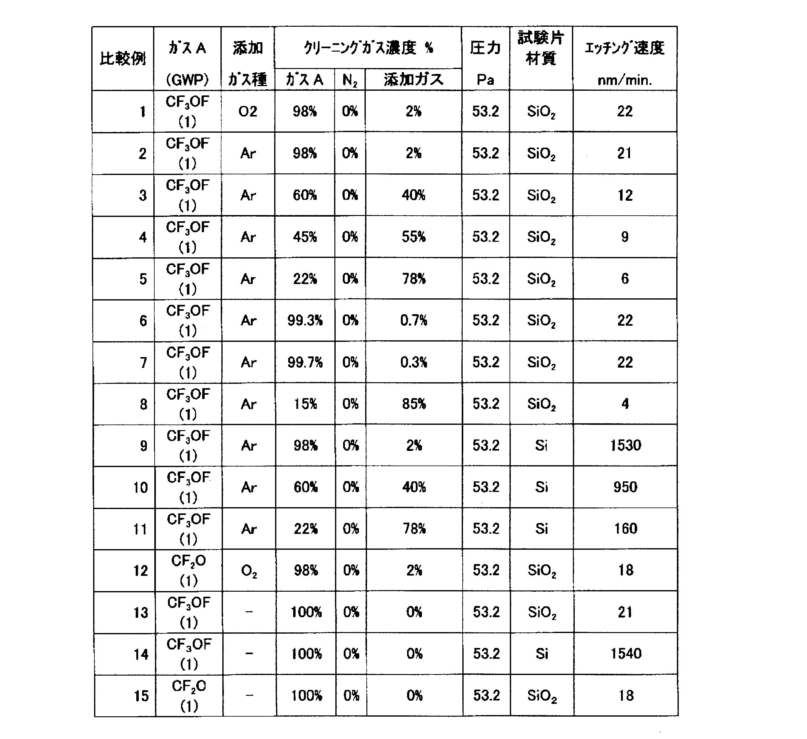
比較例1~15では、N2を含有しないクリーニングガスを用いたこと以外は実施例1~20と同様にして、試験を行った。比較例1~15のクリーニングガス組成、クリーニング条件及び試験結果を表3に示す。
さらに、以上の試験結果から、プロセス圧力が53.2Paにおけるガス成分Aの濃度に対するエッチング速度の関係のグラフを、クリーニング対象がSiO2については図2に、クリーニング対象がSiについては図3に示す。
表3に示すように、比較例1~8はガス成分Aに添加するN2を他のガス(O2又はAr)に変更した点で実施例1~6、19、及び20と異なるが、図2に示すように、N2を含有する実施例1~6、19、及び20のクリーニングガスの場合に比べ、他のガスを添加した比較例1~8のクリーニングガスの場合はエッチング速度が極端に低下していた。図3に示すように、試験片8の材質がSiであった比較例9~11についても、試験片8の材質がSiO2であった比較例1~8と変わらず、N2を含有するクリーニングガスの場合に比べ、他のガスを添加したクリーニングガスの場合はエッチング速度が極端に低下する傾向があった。ガス成分AをCF2Oとした比較例12についても同様であった。
所定量のN2をCF3OFに添加したガス組成にてリモートプラズマクリーニングをすることにより、地球温暖化係数が低いCF3OFを用いてもNF3の場合と同程度以上のエッチング速度でクリーニングが進行していることが判る。また、ガスAとしてCF2Oを用いた場合においても同様にNF3の場合と同程度以上のエッチング速度でクリーニングが進行していることが判る。即ち、地球温暖化係数の低い化合物CFxOy(例えば、CF3OF、CF2O等)であってもNF3と同等以上のクリーニング性能が得られると言える。
以上、本発明の実施形態について説明したが、本発明の趣旨を逸脱しない範囲で、当業者の通常の知識に基づいて、以下の実施形態に対し適宜変更、改良可能であることはいうまでもない。
本発明のクリーニングガスは、CVD装置のクリーニングに有用であり、特にリモートプラズマクリーニング法において、地球温暖化係数の高いNF3の代替ガスとして利用可能である。
1・・・反応チャンバー
2・・・圧力計
3・・・高周波電源
4a、4b・・・平板電極
5・・・ガス導入口
6・・・リモートプラズマ発生装置
7・・・排出口
8・・・試験片
9・・・アース
2・・・圧力計
3・・・高周波電源
4a、4b・・・平板電極
5・・・ガス導入口
6・・・リモートプラズマ発生装置
7・・・排出口
8・・・試験片
9・・・アース
Claims (5)
- CVD装置の反応チャンバー内に堆積した、Si含有物、Ge含有物、又は金属含有物を、リモートプラズマクリーニング法により除去するクリーニングガスにおいて、該クリーニングガスは一般式CFxOy[但し、xは2又は4であり、x=2のときy=1~3の整数、x=4のときy=1~4の整数を表す。]で表される化合物とN2が含有されている混合ガスであることを特徴とする、クリーニングガス。
- 一般式CFxOyで表される化合物は、CF3OF又はCF2Oであることを特徴とする、請求項1に記載のクリーニングガス。
- クリーニングガス中の一般式CFxOyで表される化合物の濃度が20vol%以上99.5vol%以下であり、かつ、クリーニングガス中のN2の濃度が0.5vol%以上80vol%以下であることを特徴とする、請求項1又は2に記載のクリーニングガス。
- 混合ガス中には、He、Ar、O2からなる群から選ばれる少なくとも1種類のガスがさらに含有されていることを特徴とする、請求項1~3のいずれか1項に記載のクリーニングガス。
- CVD装置の反応チャンバー内に堆積した、Si含有物、Ge含有物、又は金属含有物を除去するリモートプラズマクリーニング方法において、請求項1~4のいずれか1項に記載のクリーニングガスを用いることを特徴とする、リモートプラズマクリーニング方法。
Applications Claiming Priority (2)
| Application Number | Priority Date | Filing Date | Title |
|---|---|---|---|
| JP2011-036238 | 2011-02-22 | ||
| JP2011036238A JP2012174922A (ja) | 2011-02-22 | 2011-02-22 | クリーニングガス及びそれを用いたリモートプラズマクリーニング方法 |
Publications (1)
| Publication Number | Publication Date |
|---|---|
| WO2012114611A1 true WO2012114611A1 (ja) | 2012-08-30 |
Family
ID=46720413
Family Applications (1)
| Application Number | Title | Priority Date | Filing Date |
|---|---|---|---|
| PCT/JP2011/078855 Ceased WO2012114611A1 (ja) | 2011-02-22 | 2011-12-14 | クリーニングガス及びそれを用いたリモートプラズマクリーニング方法 |
Country Status (3)
| Country | Link |
|---|---|
| JP (1) | JP2012174922A (ja) |
| TW (1) | TW201237210A (ja) |
| WO (1) | WO2012114611A1 (ja) |
Cited By (2)
| Publication number | Priority date | Publication date | Assignee | Title |
|---|---|---|---|---|
| US20190148167A1 (en) * | 2017-11-16 | 2019-05-16 | Wonik Materials | Etching gas mixture, method of forming pattern by using the same, and method of manufacturing integrated circuit device by using the etching gas mixture |
| EP4099365A4 (en) * | 2020-01-30 | 2023-08-16 | Resonac Corporation | ETCHING PROCESS |
Families Citing this family (2)
| Publication number | Priority date | Publication date | Assignee | Title |
|---|---|---|---|---|
| MY182688A (en) * | 2015-01-22 | 2021-01-29 | Chia Sern Chan | Non-thermal soft plasma cleaning system |
| KR20260002287A (ko) * | 2024-06-24 | 2026-01-06 | 주식회사 히타치하이테크 | 플라스마 처리 장치 |
Citations (2)
| Publication number | Priority date | Publication date | Assignee | Title |
|---|---|---|---|---|
| JPH11236561A (ja) * | 1997-12-18 | 1999-08-31 | Central Glass Co Ltd | クリーニングガス |
| JP2006035213A (ja) * | 2004-07-22 | 2006-02-09 | Air Products & Chemicals Inc | 窒化チタンの除去方法 |
-
2011
- 2011-02-22 JP JP2011036238A patent/JP2012174922A/ja not_active Withdrawn
- 2011-12-14 WO PCT/JP2011/078855 patent/WO2012114611A1/ja not_active Ceased
- 2011-12-29 TW TW100149599A patent/TW201237210A/zh unknown
Patent Citations (2)
| Publication number | Priority date | Publication date | Assignee | Title |
|---|---|---|---|---|
| JPH11236561A (ja) * | 1997-12-18 | 1999-08-31 | Central Glass Co Ltd | クリーニングガス |
| JP2006035213A (ja) * | 2004-07-22 | 2006-02-09 | Air Products & Chemicals Inc | 窒化チタンの除去方法 |
Cited By (4)
| Publication number | Priority date | Publication date | Assignee | Title |
|---|---|---|---|---|
| US20190148167A1 (en) * | 2017-11-16 | 2019-05-16 | Wonik Materials | Etching gas mixture, method of forming pattern by using the same, and method of manufacturing integrated circuit device by using the etching gas mixture |
| US10872784B2 (en) * | 2017-11-16 | 2020-12-22 | Samsung Electronics Co., Ltd. | Etching gas mixture, method of forming pattern by using the same, and method of manufacturing integrated circuit device by using the etching gas mixture |
| EP4099365A4 (en) * | 2020-01-30 | 2023-08-16 | Resonac Corporation | ETCHING PROCESS |
| US12119233B2 (en) | 2020-01-30 | 2024-10-15 | Resonac Corporation | Etching method |
Also Published As
| Publication number | Publication date |
|---|---|
| TW201237210A (en) | 2012-09-16 |
| JP2012174922A (ja) | 2012-09-10 |
Similar Documents
| Publication | Publication Date | Title |
|---|---|---|
| US6923189B2 (en) | Cleaning of CVD chambers using remote source with cxfyoz based chemistry | |
| US7322368B2 (en) | Plasma cleaning gas and plasma cleaning method | |
| JP2004343026A (ja) | Cvd装置およびそれを用いたcvd装置のクリーニング方法 | |
| EP2159829A2 (en) | Selective etching of silicon dioxide compositions | |
| WO2012114611A1 (ja) | クリーニングガス及びそれを用いたリモートプラズマクリーニング方法 | |
| TW201529141A (zh) | 自清潔真空處理腔室 | |
| JP5214316B2 (ja) | プラズマ成膜装置のクリーニング方法 | |
| JP6480417B2 (ja) | ヒドロフルオロオレフィンエッチングガス混合物 | |
| CN103861843A (zh) | 反应腔室的清洗方法及基片刻蚀方法 | |
| TW201812897A (zh) | 電漿處理方法 | |
| CN103430290A (zh) | 干洗方法 | |
| CN101233072B (zh) | 加工衬底的方法 | |
| CN115274388B (zh) | 一种无晶圆等离子腔室的清洗方法 | |
| JP2012026020A (ja) | 平行平板電極のプラズマクリーニング方法 | |
| JP2003158123A (ja) | プラズマクリーニングガス及びプラズマクリーニング方法 | |
| CN1519889A (zh) | 半导体装置的制造设备的清洁方法 | |
| CN116145106A (zh) | 一种用于半导体镀膜工艺腔室的清洁方法 | |
| CN103996621A (zh) | 干法刻蚀方法 | |
| US7138364B2 (en) | Cleaning gas and etching gas | |
| JP2004266077A (ja) | Cvdチャンバーのクリーニング方法およびそれに用いるクリーニングガス | |
| TWI899569B (zh) | 運行電漿摻雜系統的方法與清潔系統 | |
| JP2008235562A (ja) | プラズマcvd成膜装置のクリーニング方法 | |
| JP4531467B2 (ja) | 半導体薄膜形成装置のチャンバー内のクリーニング方法 | |
| JP2003229365A (ja) | 混合クリーニングガス組成物 | |
| JP2002198357A (ja) | 半導体製造装置のクリーニングガス及びクリーニング方法 |
Legal Events
| Date | Code | Title | Description |
|---|---|---|---|
| 121 | Ep: the epo has been informed by wipo that ep was designated in this application |
Ref document number: 11859396 Country of ref document: EP Kind code of ref document: A1 |
|
| NENP | Non-entry into the national phase |
Ref country code: DE |
|
| 122 | Ep: pct application non-entry in european phase |
Ref document number: 11859396 Country of ref document: EP Kind code of ref document: A1 |