WO2012114548A1 - ハーネス部材のガイド構造 - Google Patents
ハーネス部材のガイド構造 Download PDFInfo
- Publication number
- WO2012114548A1 WO2012114548A1 PCT/JP2011/064234 JP2011064234W WO2012114548A1 WO 2012114548 A1 WO2012114548 A1 WO 2012114548A1 JP 2011064234 W JP2011064234 W JP 2011064234W WO 2012114548 A1 WO2012114548 A1 WO 2012114548A1
- Authority
- WO
- WIPO (PCT)
- Prior art keywords
- harness
- vehicle body
- guide
- side bracket
- door
- Prior art date
- Legal status (The legal status is an assumption and is not a legal conclusion. Google has not performed a legal analysis and makes no representation as to the accuracy of the status listed.)
- Ceased
Links
Images




Classifications
-
- H—ELECTRICITY
- H02—GENERATION; CONVERSION OR DISTRIBUTION OF ELECTRIC POWER
- H02G—INSTALLATION OF ELECTRIC CABLES OR LINES, OR OF COMBINED OPTICAL AND ELECTRIC CABLES OR LINES
- H02G11/00—Arrangements of electric cables or lines between relatively-movable parts
-
- B—PERFORMING OPERATIONS; TRANSPORTING
- B60—VEHICLES IN GENERAL
- B60R—VEHICLES, VEHICLE FITTINGS, OR VEHICLE PARTS, NOT OTHERWISE PROVIDED FOR
- B60R16/00—Electric or fluid circuits specially adapted for vehicles and not otherwise provided for; Arrangement of elements of electric or fluid circuits specially adapted for vehicles and not otherwise provided for
- B60R16/02—Electric or fluid circuits specially adapted for vehicles and not otherwise provided for; Arrangement of elements of electric or fluid circuits specially adapted for vehicles and not otherwise provided for electric constitutive elements
- B60R16/0207—Wire harnesses
- B60R16/0215—Protecting, fastening and routing means therefor
Definitions
- the present invention relates to a guide structure of a harness member that guides a harness member wired from the vehicle body side toward a back door that is connected to the vehicle body by an hinge structure so as to be opened and closed.
- a back door is arranged at the rear of the vehicle so that the rear of the vehicle can be used as a cargo room.
- a back door there is known a door-opening type in which the door opening and closing method spreads to the left and right.
- Such a back door also has a function as a rear panel of the vehicle while having a function as a door to be opened and closed. For this reason, even in such a back door, electrical components such as a brake lamp and an electromagnetic lock are disposed as in the case of a general rear portion of a vehicle.
- the harness member used as what is called a wire harness is arrange
- the harness member is drawn from the vehicle body that forms the side panel of the vehicle to the back door that forms the rear panel of the vehicle. For this reason, the harness member between the vehicle body and the back door is not stored inside the vehicle body and the back door having such a panel structure, but is exposed in an exposed state.
- some of such back doors are connected to the vehicle body body so as to be openable and closable by a hinge structure having two rotation shafts arranged in parallel.
- the separation distance between the vehicle body and the back door is significantly different between when the back door is closed and when the back door is open.
- the separation distance between the vehicle body and the back door is an approach distance adjacent to each other when the back door is in a closed state, whereas the back door is in an open state.
- the distance is a long distance that is a separated distance that is pivoted.
- the harness member exposed to the outside in an exposed state between them allows a different separation distance between the two even when the back door is closed or the back door is open. I want to secure the length that can be.
- the rotation range of the back door with respect to the vehicle body is, for example, 270 degrees. Therefore, the rotation range can be set. Then, the separation distance between the vehicle body and the back door due to the opening and closing of the back door is more significantly different. For this reason, the length of the harness member should be set longer in order to allow such a separation distance.
- the harness member existing between the vehicle door and the back door does not hinder the opening / closing operation of the back door, and further prevents the harness member from being caught by the closing operation of the back door.
- I want to provide a structure that guides Such a structure for guiding the harness member is arranged with respect to the above-described hinge structure for connecting the back door to the vehicle body body from the viewpoint of appearance and the advantage of the number of members. I want to keep it.
- the present invention has been made in view of such circumstances, and the problem to be solved by the present invention is connected to the vehicle body body in an openable and closable manner by a hinge structure having two rotating shafts arranged in parallel.
- the harness member In the guide structure of the harness member that guides the harness member wired from the vehicle body side toward the back door, the harness member has a guide function and the length of the harness member is opened and closed in any state. The distance between the vehicle body and the vehicle body can be allowed to be an acceptable length, the back door opening / closing operation is not hindered, and the harness member is prevented from being caught by the back door closing operation.
- the harness member guide structure employs the following means. That is, the guide structure for the harness member according to the first aspect of the present invention includes a first pivot shaft and a second pivot shaft that are arranged in parallel, and a hinge structure that connects the back door to the vehicle body body so that the back door can be opened and closed.
- An intermediate support member that is pivotally coupled and pivotally coupled to the door bracket through the second pivot shaft, the vehicle body bracket and the door bracket.
- the harness member extending from the intermediate support member is bent and guided so that the bending depth can be changed to an L shape along the axial direction of the rotating shaft.
- a harness guide portion is provided, and the first harness guide portion is configured to reduce a wire length difference of the harness member caused by opening and closing of the back door by changing a bending depth of the harness member bent into an L shape.
- the harness member is guided so as to absorb.
- the harness member extending from the intermediate support member is provided by the first harness guide portion provided on either the vehicle body side bracket portion or the door side bracket portion.
- the harness member is bent and guided so that the L-shaped bending depth along the axial direction of the rotating shaft can be changed.
- the 1st harness guide part makes the bending depth which bent the length difference (line length difference) of a harness member produced by opening and closing of a back door bent to the L-shape of a harness member shallower or deeper. Can be absorbed.
- the harness member can be guided so as to absorb this wire length difference. it can.
- the harness member has a guide function while allowing the harness member to be separated from the vehicle body body in any state where the back door is opened and closed. It is possible to make the length as long as possible, and does not hinder the opening and closing operation of the back door, and further, the harness member can be prevented from being caught by the closing operation of the back door.
- the guide structure of the harness member according to the second invention is the guide structure of the harness member according to the first invention, wherein either the vehicle body side bracket portion or the door side bracket portion is provided with the intermediate support member.
- a second harness guide portion is provided for guiding the extending harness member in an L shape along the axial direction of the rotation shaft, with the bending depth being fixed, and the second harness guide portion includes the second harness guide portion. 2 occurs when the other of the vehicle body side bracket portion and the door side bracket portion is rotated relative to the intermediate support member with the rotation axis close to the harness guide portion as a rotation axis.
- the harness member is guided so as to absorb twisting of the harness member.
- the harness member extending from the intermediate support member is provided by the second harness guide portion provided on either the vehicle body side bracket portion or the door side bracket portion.
- the guide is fixed with the bending depth fixed in an L shape along the axial direction of the rotating shaft.
- the second harness guide portion rotates the other one of the vehicle body side bracket portion and the door side bracket portion relative to the intermediate support member with the rotation axis close to the second harness guide portion as the rotation axis.
- the twisting of the harness member that occurs when it is moved can be absorbed while allowing relative rotation by an L-shaped bend. As a result, even when the harness member is twisted according to the opening and closing of the back door, the harness member can be allowed to twist, and the opening and closing operation of the back door can be performed satisfactorily.
- a guide structure for a harness member according to a third aspect of the present invention is the guide structure for a harness member according to the first or second aspect, wherein the intermediate support member has a structure from the vehicle body side bracket portion to the door side bracket portion.
- An intermediate guide portion that guides the harness member in the directed section into an I-shape so as to be within the extension range of the intermediate support member is provided.
- the harness member guide structure according to the third aspect of the invention the harness member in the section from the vehicle body side bracket portion to the door side bracket portion is moved by the intermediate guide portion provided in the intermediate support member. It can be guided in an I shape so as to be within the extension range.
- the harness member in the section from the vehicle body side bracket portion toward the door side bracket portion can be guided without slack within a range that does not affect the opening and closing operation of the back door, and the opening and closing operation of the back door is possible. To improve the performance.
- a harness member guide structure is the harness member guide structure according to any one of the first to third aspects of the invention, wherein the harness covering material forms a peripheral surface on the externally exposed side of the harness member. Is characterized in that a material having a better sliding property than that of the other member is selected so that the frictional resistance at the time of sliding against the other member is reduced.
- the harness covering material is selected from materials having better sliding properties than other members so that the frictional resistance when sliding against other members is reduced. Therefore, for example, when the harness member is slid against another member when the L-shaped bending depth of the harness member is increased or decreased, the frictional resistance due to this sliding can be reduced. .
- the harness member can be slid and moved in a state where the frictional resistance is reduced, so that the length of the harness member can be set to a length with less looseness, which is an obstacle to opening and closing the back door. It can be made the smallest, and the back door can be opened and closed even better.
- the harness member has a guide function of the harness member, and the length of the harness member can be allowed to be separated from the vehicle body body in any state when the back door is opened and closed.
- the harness member can be allowed to be separated from the vehicle body body in any state when the back door is opened and closed.
- the guide structure of the harness member according to the second invention even when the harness member is twisted in response to opening and closing of the back door, the twist of the harness member can be allowed. Ensure that the opening and closing operation can be performed satisfactorily.
- the harness member in the section from the vehicle body side bracket portion to the door side bracket portion is guided without slack within a range that does not affect the operation of opening and closing the back door.
- the back door can be opened and closed more satisfactorily.
- the vehicle 10 is a van-type vehicle in which a vehicle rear chamber (reference numeral 11) is set widely so that it can be effectively used as a luggage compartment.
- Back doors 20 and 20 that are opened and closed are disposed at the rear of the vehicle 10.
- the back doors 20 and 20 are so-called double doors that open and close so as to spread in the left-right direction. That is, the back door 20 is connected to the vehicle body 15 via the hinges 30 and 30 so as to be opened and closed.
- the back door 20 has two hinges 30 and 30 attached to one side, and is connected to the vehicle body 15 so as to be opened and closed.
- the details of the hinge 30 are shown in FIG.
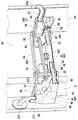
- FIG. 2 is a perspective view of the hinge 30 including the harness guide structure 40 of the wire harness 25.
- the hinge 30 is configured by a hinge structure having two rotation shafts of a first rotation shaft 37 and a second rotation shaft 38 arranged in parallel with each other.
- the back door 20 has a hinge structure that can be opened and closed within a maximum rotation range of 270 degrees.
- the hinge 30 generally includes a vehicle body side bracket member 31 as a vehicle body side bracket portion fixed to the vehicle body body 15 side, a door side bracket member 33 as a door side bracket portion fixed to the back door 20 side, An intermediate support member 35 that is pivotally connected to each of the vehicle body side bracket member 31 and the door side bracket member 33 via a first rotation shaft 37 and a second rotation shaft 38 is provided.
- the vehicle body side bracket member 31 is attached to the vehicle body 15 by an appropriate screw fastening member 39.
- the door side bracket member 33 is also attached to the back door 20 by an appropriate screw fastening member 39.
- the intermediate support member 35 is pivotally connected to the vehicle body side bracket member 31 via the first rotation shaft 37 on the vehicle body 15 side, and is pivotally connected to the vehicle body side bracket member 31 on the back door 20 side. It is pivotally connected to the door side bracket member 33 via a moving shaft 38 so as to be rotatable.
- the intermediate support member 35 is connected to the vehicle body side bracket member 31 by the first rotation shaft 37 so as to be relatively rotatable.
- the door-side bracket member 33 is connected to the intermediate support member 35 by a second rotation shaft 38 so as to be relatively rotatable.
- the back door 20 to which the door side bracket member 33 is fixed relative to the vehicle body 15 to which the vehicle body side bracket member 31 is fixed has a pivot support rotation range of the intermediate support member 35 by the first rotation shaft 37. And a pivot range in which the second pivot shaft 38 and the pivot support pivot range of the door-side bracket member 33 are added.
- the hinge 30 is provided with an opening restriction link 363 for restricting the opening angle of the back door 20 to a range of 270 degrees.
- the opening restricting link 363 is connected to the vehicle body side bracket member 31 so that the back door 20 can be opened and closed while maintaining the relative distance between the vehicle body side bracket member 31 and the door side bracket member 33. It is suspended with respect to both the door side bracket member 33.
- the maximum opening angle of the back door 20 is set to an opening angle of 270 degrees.
- the opening restriction link 363 functions to maintain the relative distance of the door side bracket member 33 with respect to the vehicle body side bracket member 31. Therefore, when the back door 20 is opened and closed with respect to the vehicle body 15, the relative position of the door side bracket member 33 with respect to the intermediate support member 35 changes, and the relative position of the vehicle body side bracket member 31 with respect to the intermediate support member 35 also changes. Will change. That is, when the back door 20 is opened and closed with respect to the vehicle body 15, the vehicle body side bracket member 31 and the door side bracket member 33 are interlocked with each other with respect to the intermediate support member 35. The relative position with respect to the intermediate support member 35 changes.
- the back door 20 has a function as a rear panel of the vehicle as well as a general vehicle.
- the back door 20 is provided with electric parts such as a brake lamp and an electromagnetic lock.
- a so-called wire harness 25 in which a power supply wire and a control signal transmission wire are bundled from the body body 15 constituting the side panel of the vehicle toward the back door 20 constituting the rear panel of the vehicle. It is arranged.
- the wire harness 25 is a member corresponding to the harness member according to the present invention.
- the wire harness 25 is pulled out from a drawer port 251 that communicates with the inside of the panel structure that forms the vehicle body 15, and is pulled into a service port 252 that communicates with the interior of the panel structure that forms the back door 20.
- the harness guide structure 40 corresponds to the guide structure of the harness member according to the present invention.
- the wire harness 25 will be described. Although the wire harness 25 is difficult to understand in the drawing, the outer periphery is covered and exposed to the outside so as to cover the power supply wire and the control signal transmission wire. Is provided with a harness covering material 26 (reference numeral shown in FIG. 2). As the harness covering material 26, a material having a better sliding property is selected than various protectors 41, 51, 61 described later.
- protectors 41, 51, and 61 are members corresponding to other members according to the present invention, and form a harness guide structure 40 that guides the wire harness 25 described later. For this reason, the wire harness 25 strikes against these protectors 41, 51, 61. That is, when the wire harness 25 is slid against the protectors 41, 51, 61, a material having a better sliding property than the protectors 41, 51, 61 is selected so as to reduce the frictional resistance generated between them. ing.
- the wire harness 25 wired between the vehicle body 15 side and the back door 20 side is guided by the following harness guide structure 40 of the wire harness 25.
- the harness guide structure 40 includes protectors 41, 51, 51, 51, 51, 51, 51, 51, 51, 51, 51, 51, 51, 51, 51, 51, 51, 51, 51, 51, 51. 61 is provided. Therefore, the protectors 41, 51, 61 are components separated from each other corresponding to the vehicle body side bracket member 31, the door side bracket member 33, and the intermediate support member 35 that constitute the hinge 30.
- the harness guide structure 40 is roughly composed of a vehicle body side protector 41 that is appropriately fixed and attached to the vehicle body side bracket member 31, a door side protector 51 that is appropriately fixed and attached to the door side bracket member 33, And an intermediate protector 61 that is fixed and attached to the intermediate support member 35 as appropriate.
- the vehicle body side protector 41 corresponds to the first harness guide portion according to the present invention
- the door side protector 51 corresponds to the second harness guide portion according to the present invention
- the intermediate protector 61 corresponds to the intermediate guide portion according to the present invention. Equivalent to.
- the vehicle body side protector 41, the door side protector 51, and the intermediate protector 61 are exposed to the outside between the vehicle body 15 that forms the side panel of the vehicle and the back door 20 that forms the rear panel of the vehicle.
- the harness 25 is guided. Next, details of each of the vehicle body side protector 41, the door side protector 51, and the intermediate protector 61 will be described.
- FIG. 3 is a front external view showing the vehicle body side protector 41 as viewed from the front.
- the vehicle body side protector 41 has a function of guiding the wire harness 25 in the vehicle body side bracket member 31 by bending it into an L shape along the rotation axis direction (axial direction) of the first rotation shaft 37.
- the vehicle body side protector 41 is formed so as to bend and guide the wire harness 25 between the vehicle body 15 side drawer port 251 and the intermediate support member 35.
- the vehicle body side protector 41 is formed in a cylindrical shape having a substantially L-shaped outer shape through which the wire harness 25 can be inserted.
- the vehicle body side protector 41 has a substantially L-shaped outer shape including a guide inlet portion 42 that opens toward the drawer opening 251 on the vehicle body body 15 side, and a guide outlet portion 43 that opens toward the intermediate support member 35 side. It is formed as a cylindrical resin molded product. For this reason, the opening direction of the guide inlet part 42 and the opening direction of the guide outlet part 43 are set in directions orthogonal to each other. The opening directions of the guide inlet portion 42 and the guide outlet portion 43 are open along the extending plane direction of the vehicle body side bracket member 31. Further, a bent portion 44 between the guide inlet portion 42 and the guide outlet portion 43 of the vehicle body side protector 41 is formed in a shape that bends at a right angle in order to bend the wire harness 25 into an L shape. .
- the bent portion 44 is a portion that accommodates the wire harness 25 bent in an L shape, and the wire harness 25 can be changed so that the bending depth (bending amount) of the wire harness 25 bent in an L shape can be changed. Contained. For this reason, in the case of the reference numeral 255 in which the bending depth (bending amount) of the wire harness 25 becomes shallow, the bending portion 44 has a shortcut distance (shortcut) so as to correspond to the bending amount of the shallow wire harness 25. An inclined wall 45 is formed. On the other hand, the bent portion 44 corresponds to the bending amount of the deep wire harness 25 as shown in FIG. 2 in the case of the reference numeral 256 in which the bending depth (bending amount) of the wire harness 25 is deep.
- An overhanging wall 46 is formed so as to extend in the width direction of the L-shaped bend.
- the vehicle body side protector 41 changes the depth of bending of the wire harness 25 into the L shape, and absorbs the wire length difference of the wire harness 25 caused by opening and closing of the back door 20.
- the inlet guide wall indicated by reference numeral 471 guides the wire harness 25 toward the outlet 251, and the outlet guide wall indicated by reference numeral 472 guides the wire harness 25 toward the intermediate support member 35. It is.
- Reference numeral 48 denotes a fixing ring for positioning and fixing the wire harness 25 in the vicinity of the guide inlet portion 42 in the vehicle body side protector 41.
- the fixing ring 48 is directed from the fixing ring 48 to the inside of the vehicle body side protector 41 without affecting the wire harness 25 in the section from the fixing ring 48 to the drawer port 251 of the vehicle body 15.
- Reference numeral 49 denotes a screw member used when the vehicle body side protector 41 is fixedly attached to the vehicle body side bracket member 31.
- the reference numeral 361 is a structure for attaching the door-side protector 51 to the door-side bracket member 33
- the indicated numeral 362 is a structure for attaching the intermediate protector 61 to the intermediate support member 35.
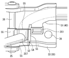
- FIG. 4 is a front external view showing the door-side protector 51 as viewed from the front.
- the door protector 51 has a function of guiding the wire harness 25 extending from the intermediate support member 35 by bending it in an L shape along the rotation axis direction (axial direction) of the second rotation shaft 38. At this time, the bending depth of the wire harness 25 by the door-side protector 51 is supported and fixed by the bending guide shape 54 of the guide inlet portion 52.
- the door-side protector 51 is formed so as to bend and guide the wire harness 25 between the intermediate support member 35 and the drawer door 252 on the back door 20 side. Has been. That is, as shown in FIGS.
- the door-side protector 51 is formed as a cylindrical resin molded product so that the wire harness 25 can be inserted therein.
- the door-side protector 51 is provided with a guide entrance 52 that opens in a direction orthogonal to the rotational axis direction of the second rotational shaft 38.
- the door-side protector 51 is provided with a guide outlet 53 that opens in a direction orthogonal to the rotation axis direction of the second rotation shaft 38 toward the drawer port 252 side on the back door 20 side. ing.
- the opening direction of the guide inlet portion 52 and the opening direction of the guide outlet portion 53 are also set in directions orthogonal to each other.
- the guide entrance 52 is disposed at a position adjacent to the second rotation shaft 38.
- the opening direction of the guide inlet portion 52 is set to a direction intersecting with the extending plane direction of the door side bracket member 33.
- the opening direction of the guide inlet portion 52 is set in a direction away from the extending plane of the door-side bracket member 33.
- the opening direction of the guide outlet portion 53 opens along the extending plane direction of the door-side bracket member 33.
- the bending depth of the L-shape of the wire harness 25 by the door side protector 51 is ensured to be substantially perpendicular. That is, the bent portion of the wire harness 25 illustrated by the reference numeral 257 has a substantially right-angle shape.
- the door-side bracket member 33 side of the L-shape (bent portion 257) where the wire harness 25 is bent is set in a direction along the rotation axis (axis) direction of the second rotation shaft 38. .
- a bending guide shape 54 is provided on the peripheral edge of the guide inlet portion 52 of the door-side protector 51.
- the bending guide shape 54 guides the wire harness 25 so as to bend the wire harness 25 in the orthogonal direction intersecting the rotation axis direction of the second rotation shaft 38.
- the bending guide shape 54 is formed to have a wall structure along the bending direction so that the wire harness 25 is bent at a substantially right angle in an L shape from the intermediate support member 35 toward the door side protector 51. . That is, the end edge portion of the bending guide shape 54 is provided with an end flange 55 having a guide function for bending the wire harness 25 in an L-shape at a substantially right angle.
- the end flange 55 is formed so as to extend in a direction intersecting the opening direction of the guide inlet portion 52.
- the edge flange 55 guides the wire harness 25 that is pulled out from the intermediate support member 35 side and enters the door side protector 51 from the guide entrance 52 toward the door side protector 51.
- a portion of the end flange 55 that is closest to the second rotation shaft 38 is formed in a rounded shape that covers the second rotation shaft 38.
- the interior from the guide inlet portion 52 to the guide outlet portion 53 is formed so as to guide the wire harness 25 along the extending plane of the door side bracket member 33.
- the bending depth of the wire harness 25 by the door protector 51 is fixed by the bending portion 257 of the wire harness 25 determined by the bending guide shape 54 provided in the guide entrance portion 52. That is, the bent portion 257 of the wire harness 25 formed by the bending guide shape 54 of the door-side protector 51 abuts on the inside of the door-side protector 51 so as to regulate the relative movement of the wire harness 25 inside the door-side protector 51. ing. Further, the bent portion 257 of the wire harness 25 guided by the door protector 51 in this way will be described later, but the second rotating shaft 38 close to the door protector 51 is used as a rotating axis. The twist of the wire harness 25 that occurs when the door-side bracket member 33 is rotated relative to the support member 35 is absorbed.
- the outlet guide wall 57 shown in the figure is for guiding the wire harness 25 toward the drawing port 252.
- FIG. 5 is a front external view showing the intermediate protector 61 as viewed from the front.
- the intermediate protector 61 has a function of guiding the wire harness 25 in the section from the vehicle body side bracket member 31 to the door side bracket member 33 in an I shape so as to be within the extension range of the intermediate support member 35. Therefore, specifically, as shown in FIGS. 2 and 5, the intermediate protector 61 is formed as a cylindrical resin molded product so that the wire harness 25 can be inserted therein.
- the intermediate protector 61 is provided with a guide inlet portion 62 that opens toward the first rotation shaft 37 and a guide outlet portion 63 that opens toward the second rotation shaft 38.
- the opening directions of the guide inlet portion 62 and the guide outlet portion 63 are open in the same line direction along the extending plane direction of the intermediate support member 35 in order to guide the wire harness 25 in an I shape.
- symbol 64 is for guiding the wire harness 25 from the vehicle body side protector 41 (vehicle body side bracket member 31) side toward the guide entrance part 62.
- An exit guide wall denoted by reference numeral 65 is for guiding the wire harness 25 from the guide exit portion 63 toward the door-side protector 51 (door-side bracket member 33).
- the inlet guide wall 64 and the outlet guide wall 65 are arranged so as to guide the wire harness 25 exposed to the outside in a section from the vehicle body side protector 41 to the door side protector 51 in a slippery manner.
- the arrangement range of the inlet guide wall 64 and the outlet guide wall 65 is relative to the intermediate support member 35, the first rotation shaft 37, and the second rotation shaft 38 that the wire harness 25 hits. It is formed over a range that covers this. Accordingly, the wire harness 25 in the section from the vehicle body side protector 41 to the door side protector 51 is guided by the intermediate protector 61 so as to be smoothly slidable.
- FIG. 6 is a top view showing a state in which the back door 20 is open.
- FIG. 7 is a top view showing a state in which the back door 20 is closed. That is, according to the harness guide structure 40 described above, the wire harness 25 extending toward the intermediate support member 35 is rotated by the first rotation shaft 37 by the vehicle body side protector 41 provided on the vehicle body side bracket member 31. The wire harness 25 is bent and guided so that the L-shaped bending depth along the direction of the movement axis (axis) can be changed.
- the vehicle body side protector 41 can absorb the length difference (line length difference) of the wire harness 25 caused by opening and closing of the back door 20 as follows.
- the bending depth of the wire harness 25 bent in an L shape is made shallower like the wire harness indicated by reference numeral 255 in FIG. 3. be able to.
- the bending depth can be increased as in the wire harness indicated by the reference numeral 256 in FIG.
- the wire harness 25 is absorbed so as to absorb this wire length difference. Can be guided.
- the wire harness 25 can have a guide function of the wire harness 25, and the length of the wire harness 25 can be allowed to be separated from the vehicle body 15 in any state where the back door 20 is opened and closed. Further, it is possible to prevent the wire harness 25 from being caught by the closing operation of the back door 20 without hindering the opening and closing operation of the back door 20.
- the wire harness 25 extending from the intermediate support member 35 is connected to the rotation axis of the second rotation shaft 38 by the door side protector 51 provided on the door side bracket member 33.
- a guide is made by fixing the bending depth in an L shape along the (axis) direction. In this case, the bending depth of the L-shape of the wire harness 25 is ensured to be substantially perpendicular.
- a part of the L shape in which the wire harness 25 is bent at this time is set in a direction along the rotation axis (axis) direction of the second rotation shaft 38.
- the door-side protector 51 is generated when the vehicle body side bracket member 31 is rotated relative to the intermediate support member 35 with the second rotation shaft 38 adjacent to the door-side protector 51 as the rotation axis.
- the twist of the wire harness 25 can be absorbed while allowing relative rotation by the L-shaped bent portion 257 in which the bending depth that is substantially perpendicular is ensured.
- the twisting of the wire harness 25 can be allowed, and the back door 20 can be opened and closed satisfactorily.
- the intermediate protector 61 provided on the intermediate support member 35 allows the wire harness 25 in the section from the vehicle body side bracket member 31 to the door side bracket member 33 to be connected to the intermediate support member 35. It can be guided in an I shape so as to be within the extension range of Accordingly, the wire harness 25 in the section from the vehicle body side bracket member 31 to the door side bracket member 33 can be guided without slack within a range that does not affect the opening / closing operation of the back door 20, and the back door can be guided. The opening / closing operation 20 can be performed more satisfactorily.
- the harness member guide structure according to the present invention is not limited to the harness guide structure 40 of the above-described embodiment, and may be configured by appropriately changing locations as follows. Good. That is, in the harness guide structure 40 described above, the protector 41 corresponding to the first harness guide portion is provided on the vehicle body side bracket member 31. However, the protector corresponding to the first harness guide portion according to the present invention is not limited to being provided on the vehicle body side bracket member 31, and is instead provided on the door side bracket member 33. It's okay. In such a case, the protector corresponding to the second harness guide part according to the present invention is provided for the vehicle body side bracket member 31 instead of being provided for the door side bracket member 33. Become.
- the intermediate harness 61 guides the wire harness 25 in an I shape so as to be within the extension range of the intermediate support member 35.
- an intermediate protector 61 may be provided, for example, so as to be located in a portion that deviates vertically from the extending range of the intermediate support member 35.
Landscapes
- Engineering & Computer Science (AREA)
- Mechanical Engineering (AREA)
- Electric Cable Arrangement Between Relatively Moving Parts (AREA)
- Details Of Indoor Wiring (AREA)
Abstract
車体側ブラケット部材(31)に設けられた車体側プロテクタ(41)により、中間支持部材(35)に向けて延在するワイヤーハーネス(25)を、第1回動軸(37)の回動軸線方向に沿ったL字形の屈曲深さを変えることができるようにワイヤーハーネス(25)を屈曲させてガイドしている。ここで、車体側プロテクタ(41)は、バックドア(20)の開閉により生ずるワイヤーハーネス(25)の長さの差を吸収することができるように、ワイヤーハーネス(25)のL字形に屈曲した屈曲深さを浅くしたり深くしたりすることができるようになっている。これによって、ワイヤーハーネス(25)のガイド機能を有しつつ、ワイヤーハーネス(25)の長さをバックドアが開け閉めいずれの状態でも車体ボデーとの離間距離を許容できる長さとすることができる。
Description
本発明は、ヒンジ構造により車体ボデーに開閉可能に連結されるバックドアに向けて該車体ボデー側から配線されるハーネス部材をガイドするハーネス部材のガイド構造に関する。
例えばバンタイプの車両にあっては、車両後室を荷室として利用することができるように、車両後部にバックドアが配設されている。このようなバックドアには、ドアの開閉方式が左右に広がるようにした観音開き式となるものが知られている。このようなバックドアは、開閉されるドアとしての機能を有しつつも、車両の後部パネルとしての機能も有する。このため、このようなバックドアにあっても、一般の車両後部と同様、ブレーキランプや電磁式ロック等の電装部品が配設されている。このため、このようなランプ装置に向けて電力供給することができるように、車体ボデー側からバックドア側に向けて、いわゆるワイヤーハーネスとなるハーネス部材が配設されている(例えば、特許文献1および特許文献2参照)。なお、このハーネス部材は、車両の側部パネルをなす車体ボデーから車両の後部パネルをなすバックドアへと引き込んでいる。このため、車体ボデーとバックドアとの間におけるハーネス部材は、このようなパネル構造をなす車体ボデー内部およびバックドア内部には収納されずに、外部に剥き出しにされた状態で露出されている。
ところで、このようなバックドアには、2つの平行配置される回動軸を具備するヒンジ構造により車体ボデーに開閉可能に連結されているものがある。このため、車体ボデーとバックドアとの間の離間距離は、バックドアが閉め状態となっている場合と、バックドアが開き状態となっている場合とで顕著に相違している。具体的には、車体ボデーとバックドアとの間の離間距離は、バックドアが閉め状態となっている場合には互いに隣接する接近距離となるに対し、バックドアが開き状態となっている場合には軸回動した離間距離となる長い距離となる。このため、これらの間にて剥き出し状態で外部に露出されるハーネス部材は、バックドアが閉め状態となっていても、バックドアが開き状態となっていても、両者の異なる離間距離を許容することができる長さを確保しておきたい。
なお、バックドアを車体ボデーに開閉可能に連結する上記したヒンジ構造に、2つの回動軸を平行に配置した構造を採用した場合には、車体ボデーに対するバックドアの回動範囲を例えば270度となるような回動範囲に設定することができることとなる。そうすると、バックドアの開け閉めによる車体ボデーとバックドアとの間の離間距離は、より顕著に相違することとなる。このため、ハーネス部材の長さは、このような離間距離を許容するためにより長く設定しておきたい。
なお、バックドアを車体ボデーに開閉可能に連結する上記したヒンジ構造に、2つの回動軸を平行に配置した構造を採用した場合には、車体ボデーに対するバックドアの回動範囲を例えば270度となるような回動範囲に設定することができることとなる。そうすると、バックドアの開け閉めによる車体ボデーとバックドアとの間の離間距離は、より顕著に相違することとなる。このため、ハーネス部材の長さは、このような離間距離を許容するためにより長く設定しておきたい。
しかしながら、ハーネス部材を単に長く設定したのでは、バックドアの開け閉め動作を阻害したり、バックドアを閉める際にハーネス部材を挟み込んでしまうことにもなりかねない。このため、この車両ドアとバックドアとの間に存するハーネス部材を、バックドアの開け閉め動作を阻害せず、さらにバックドアの閉め動作により挟み込まれてしまうのも防止するように、このハーネス部材をガイドする構造を設けておきたい。なお、このようなハーネス部材をガイドする構造は、外観上の観点からも、部材点数の有利さの点からも、車体ボデーに対してバックドアを連結する上記したヒンジ構造に対して配設しておきたい。
本発明は、このような事情に鑑みなされたものであって、本発明が解決しようとする課題は、2つの平行配置される回動軸を具備するヒンジ構造により車体ボデーに開閉可能に連結されるバックドアに向けて該車体ボデー側から配線されるハーネス部材をガイドするハーネス部材のガイド構造において、ハーネス部材のガイド機能を有しつつハーネス部材の長さをバックドアが開け閉めいずれの状態でも車体ボデーとの離間距離を許容できる長さとすることができるようにし、バックドアの開け閉め動作を阻害せず、さらにバックドアの閉め動作によるハーネス部材の挟み込まれの防止を図ることにある。
上記した課題を解決するために、本発明に係るハーネス部材のガイド構造は次の手段を採用する。
すなわち、本発明の第1の発明に係るハーネス部材のガイド構造は、平行配置される第1回動軸および第2回動軸を具備して車体ボデーにバックドアを開閉可能に連結するヒンジ構造に対して配設され、該車体ボデー側から該バックドア側までの間における該車体ボデー側から該バックドアに配線されるハーネス部材をガイドするハーネス部材のガイド構造であって、前記ヒンジ構造は、前記車体ボデー側に固定される車体側ブラケット部と、前記バックドア側に固定されるドア側ブラケット部と、前記車体側ブラケット部に対して前記第1回動軸を介して回動可能に軸支連結され且つ前記ドア側ブラケット部に対して前記第2回動軸を介して回動可能に軸支連結される中間支持部材とを備え、前記車体側ブラケット部および前記ドア側ブラケット部のいずれか一方には、前記中間支持部材から延在する前記ハーネス部材を前記回動軸の軸方向に沿ってL字形に屈曲深さが変えられるように屈曲させてガイドする第1ハーネスガイド部が設けられており、該第1ハーネスガイド部は、前記ハーネス部材のL字形に屈曲した屈曲の深さが変わることにより、前記バックドアの開閉により生ずる前記ハーネス部材の線長差を吸収するように該ハーネス部材をガイドすることを特徴とする。
すなわち、本発明の第1の発明に係るハーネス部材のガイド構造は、平行配置される第1回動軸および第2回動軸を具備して車体ボデーにバックドアを開閉可能に連結するヒンジ構造に対して配設され、該車体ボデー側から該バックドア側までの間における該車体ボデー側から該バックドアに配線されるハーネス部材をガイドするハーネス部材のガイド構造であって、前記ヒンジ構造は、前記車体ボデー側に固定される車体側ブラケット部と、前記バックドア側に固定されるドア側ブラケット部と、前記車体側ブラケット部に対して前記第1回動軸を介して回動可能に軸支連結され且つ前記ドア側ブラケット部に対して前記第2回動軸を介して回動可能に軸支連結される中間支持部材とを備え、前記車体側ブラケット部および前記ドア側ブラケット部のいずれか一方には、前記中間支持部材から延在する前記ハーネス部材を前記回動軸の軸方向に沿ってL字形に屈曲深さが変えられるように屈曲させてガイドする第1ハーネスガイド部が設けられており、該第1ハーネスガイド部は、前記ハーネス部材のL字形に屈曲した屈曲の深さが変わることにより、前記バックドアの開閉により生ずる前記ハーネス部材の線長差を吸収するように該ハーネス部材をガイドすることを特徴とする。
この第1の発明に係るハーネス部材のガイド構造によれば、車体側ブラケット部およびドア側ブラケット部のいずれか一方に設けられた第1ハーネスガイド部により、中間支持部材から延在するハーネス部材を、回動軸の軸方向に沿ったL字形の屈曲深さを変えることができるようにハーネス部材を屈曲させてガイドする。ここで、第1ハーネスガイド部は、バックドアの開閉により生ずるハーネス部材の長さの差(線長差)を、ハーネス部材のL字形に屈曲した屈曲深さを浅くしたり深くしたりすることで吸収することができる。これによって、バックドアの開け閉めにより車体ボデー側とバックドア側との間のハーネス部材の線長差が生ずるような場合でも、この線長差を吸収するように該ハーネス部材をガイドすることができる。もって、この第1の発明に係るハーネス部材のガイド構造によれば、ハーネス部材のガイド機能を有しつつハーネス部材の長さをバックドアの開け閉めいずれの状態でも車体ボデーとの離間距離を許容できる長さにでき、バックドアの開け閉め動作を阻害せず、さらにバックドアの閉め動作によるハーネス部材の挟み込まれを防止することができる。
第2の発明に係るハーネス部材のガイド構造は、前記第1の発明に係るハーネス部材のガイド構造において、前記車体側ブラケット部および前記ドア側ブラケット部のいずれか他方には、前記中間支持部材から延在する前記ハーネス部材を前記回動軸の軸方向に沿ってL字形に屈曲深さを固定させてガイドする第2ハーネスガイド部が設けられており、該第2ハーネスガイド部は、該第2ハーネスガイド部に近接する前記回動軸を回動軸線として前記中間支持部材に対して前記車体側ブラケット部および前記ドア側ブラケット部のいずれか他方を相対的に回動させた場合に生ずる、前記ハーネス部材の捩じれを吸収するように該ハーネス部材をガイドすることを特徴とする。
この第2の発明に係るハーネス部材のガイド構造によれば、車体側ブラケット部およびドア側ブラケット部のいずれか他方に設けられた第2ハーネスガイド部により、中間支持部材から延在するハーネス部材を、回動軸の軸方向に沿ってL字形に屈曲深さを固定させてガイドする。ここで、第2ハーネスガイド部は、第2ハーネスガイド部に近接する回動軸を回動軸線として中間支持部材に対して車体側ブラケット部およびドア側ブラケット部のいずれか他方を相対的に回動させた場合に生ずる、ハーネス部材の捩じれをL字形の屈曲により相対的な回動を許容して吸収することができる。これによって、バックドアの開け閉めに応じてハーネス部材に捩じれが生じるような場合でも、このハーネス部材の捩じれを許容することができることとなり、バックドアの開け閉め動作を良好に行えるようにする。
この第2の発明に係るハーネス部材のガイド構造によれば、車体側ブラケット部およびドア側ブラケット部のいずれか他方に設けられた第2ハーネスガイド部により、中間支持部材から延在するハーネス部材を、回動軸の軸方向に沿ってL字形に屈曲深さを固定させてガイドする。ここで、第2ハーネスガイド部は、第2ハーネスガイド部に近接する回動軸を回動軸線として中間支持部材に対して車体側ブラケット部およびドア側ブラケット部のいずれか他方を相対的に回動させた場合に生ずる、ハーネス部材の捩じれをL字形の屈曲により相対的な回動を許容して吸収することができる。これによって、バックドアの開け閉めに応じてハーネス部材に捩じれが生じるような場合でも、このハーネス部材の捩じれを許容することができることとなり、バックドアの開け閉め動作を良好に行えるようにする。
第3の発明に係るハーネス部材のガイド構造は、前記第1または前記第2の発明に係るハーネス部材のガイド構造において、前記中間支持部材には、前記車体側ブラケット部から前記ドア側ブラケット部に向けた区間における前記ハーネス部材を、該中間支持部材の延在範囲内に収まるようにI字形にガイドする中間ガイド部が設けられていることを特徴とする。
この第3の発明に係るハーネス部材のガイド構造によれば、中間支持部材に設けられた中間ガイド部により、車体側ブラケット部からドア側ブラケット部に向けた区間におけるハーネス部材を、中間支持部材の延在範囲内に収まるようにI字形にガイドすることができる。これによって、車体側ブラケット部からドア側ブラケット部に向けた区間におけるハーネス部材を、バックドアの開け閉め動作に影響を与えない範囲内で弛みなくガイドすることができて、バックドアの開け閉め動作をさらに良好に行えるようにする。
この第3の発明に係るハーネス部材のガイド構造によれば、中間支持部材に設けられた中間ガイド部により、車体側ブラケット部からドア側ブラケット部に向けた区間におけるハーネス部材を、中間支持部材の延在範囲内に収まるようにI字形にガイドすることができる。これによって、車体側ブラケット部からドア側ブラケット部に向けた区間におけるハーネス部材を、バックドアの開け閉め動作に影響を与えない範囲内で弛みなくガイドすることができて、バックドアの開け閉め動作をさらに良好に行えるようにする。
第4の発明に係るハーネス部材のガイド構造は、前記第1から前記第3のいずれかの発明に係るハーネス部材のガイド構造において、前記ハーネス部材の外部露出側の周面を形成するハーネス被覆材は、他の部材に摺り当たる際の摩擦抵抗が小さくなるように、該他の部材より滑り性質の良い素材が選択されていることを特徴とする。
この第4の発明に係るハーネス部材のガイド構造によれば、ハーネス被覆材は、他の部材に摺り当たる際の摩擦抵抗が小さくなるように、他の部材より滑り性質の良い素材が選択されているので、例えばハーネス部材のL字形の屈曲深さを深くしたり浅くしたりした際にハーネス部材が他の部材に摺り当たることがあっても、この摺り当りによる摩擦抵抗を小さくすることができる。これによって、摩擦抵抗の小さくした状態でハーネス部材を摺り動かすことができるので、このハーネス部材の長さを緩みの少ない長さに設定することができて、バックドアの開け閉め動作の阻害要因を最も小さくすることができて、バックドアの開け閉め動作をさらにもっと良好に行えるようにすることができる。
この第4の発明に係るハーネス部材のガイド構造によれば、ハーネス被覆材は、他の部材に摺り当たる際の摩擦抵抗が小さくなるように、他の部材より滑り性質の良い素材が選択されているので、例えばハーネス部材のL字形の屈曲深さを深くしたり浅くしたりした際にハーネス部材が他の部材に摺り当たることがあっても、この摺り当りによる摩擦抵抗を小さくすることができる。これによって、摩擦抵抗の小さくした状態でハーネス部材を摺り動かすことができるので、このハーネス部材の長さを緩みの少ない長さに設定することができて、バックドアの開け閉め動作の阻害要因を最も小さくすることができて、バックドアの開け閉め動作をさらにもっと良好に行えるようにすることができる。
第1の発明に係るハーネス部材のガイド構造によれば、ハーネス部材のガイド機能を有しつつハーネス部材の長さをバックドアが開け閉めいずれの状態でも車体ボデーとの離間距離を許容できる長さとすることができるようにし、バックドアの開け閉め動作を阻害せず、バックドアの閉め動作によるハーネス部材の挟み込まれを防止することができる。
第2の発明に係るハーネス部材のガイド構造によれば、バックドアの開け閉めに応じてハーネス部材に捩じれが生じるような場合でも、このハーネス部材の捩じれを許容することができることとなり、バックドアの開け閉め動作を良好に行えるようにする。
第3の発明に係るハーネス部材のガイド構造によれば、車体側ブラケット部からドア側ブラケット部に向けた区間におけるハーネス部材を、バックドアの開け閉め動作に影響を与えない範囲内で弛みなくガイドすることができて、バックドアの開け閉め動作をさらに良好に行えるようにする。
第4の発明に係るハーネス部材のガイド構造によれば、バックドアの開け閉め動作の阻害要因を最も小さくすることができて、バックドアの開け閉め動作をさらにもっと良好に行えるようにすることができる。
第2の発明に係るハーネス部材のガイド構造によれば、バックドアの開け閉めに応じてハーネス部材に捩じれが生じるような場合でも、このハーネス部材の捩じれを許容することができることとなり、バックドアの開け閉め動作を良好に行えるようにする。
第3の発明に係るハーネス部材のガイド構造によれば、車体側ブラケット部からドア側ブラケット部に向けた区間におけるハーネス部材を、バックドアの開け閉め動作に影響を与えない範囲内で弛みなくガイドすることができて、バックドアの開け閉め動作をさらに良好に行えるようにする。
第4の発明に係るハーネス部材のガイド構造によれば、バックドアの開け閉め動作の阻害要因を最も小さくすることができて、バックドアの開け閉め動作をさらにもっと良好に行えるようにすることができる。
以下、本発明に係るハーネス部材のガイド構造を実施するための形態について図面を参照しながら説明する。図1の車両外観図では、バンタイプの車両10の後部外観を示している。車両10は、荷物室として有効活用できるように車両後室(図示符号11部分)が広く設定されたバンタイプの車両である。この車両10の後部には、開け閉めされるバックドア20,20が配設されている。このバックドア20,20は、左右方向に広がるように開閉する、いわゆる観音開き式となっている。すなわち、このバックドア20は、ヒンジ30,30を介して車体ボデー15に開閉可能に連結されている。なお、このバックドア20は、片側につき2つのヒンジ30,30が取り付けられ、車体ボデー15に対して開閉可能に連結されている。なお、ヒンジ30の詳細は図2にて図示されている。図2は、ワイヤーハーネス25のハーネスガイド構造40を含むヒンジ30を斜視にて示している。
図2に示すように、ヒンジ30は、互いに平行配置される第1回動軸37と第2回動軸38との2つ回動軸を有したヒンジ構造により構成され、車体ボデー15に対してバックドア20を最大270度の回動範囲で開閉することができるヒンジ構造となっている。このヒンジ30は、概略、車体ボデー15側に固定される車体側ブラケット部としての車体側ブラケット部材31と、バックドア20側に固定されるドア側ブラケット部としてのドア側ブラケット部材33と、これらの車体側ブラケット部材31およびドア側ブラケット部材33のそれぞれに対して第1回動軸37および第2回動軸38を介して軸支連結される中間支持部材35とを備えている。
車体側ブラケット部材31は、適宜の螺子止め部材39により車体ボデー15に対して取り付けられる。ドア側ブラケット部材33も、適宜の螺子止め部材39によりバックドア20に対して取り付けられる。ここで中間支持部材35は、車体ボデー15側では第1回動軸37を介して車体側ブラケット部材31に対して回動可能に軸支連結されているとともに、バックドア20側では第2回動軸38を介してドア側ブラケット部材33に対して回動可能に軸支連結されている。このため、この中間支持部材35は、第1回動軸37により車体側ブラケット部材31に対して相対回動可能に連結されている。また、ドア側ブラケット部材33は、第2回動軸38により中間支持部材35に対して相対回動可能に連結されている。
車体側ブラケット部材31は、適宜の螺子止め部材39により車体ボデー15に対して取り付けられる。ドア側ブラケット部材33も、適宜の螺子止め部材39によりバックドア20に対して取り付けられる。ここで中間支持部材35は、車体ボデー15側では第1回動軸37を介して車体側ブラケット部材31に対して回動可能に軸支連結されているとともに、バックドア20側では第2回動軸38を介してドア側ブラケット部材33に対して回動可能に軸支連結されている。このため、この中間支持部材35は、第1回動軸37により車体側ブラケット部材31に対して相対回動可能に連結されている。また、ドア側ブラケット部材33は、第2回動軸38により中間支持部材35に対して相対回動可能に連結されている。
これにより、車体側ブラケット部材31が固定される車体ボデー15に対して、ドア側ブラケット部材33が固定されるバックドア20は、第1回動軸37による中間支持部材35の軸支回動範囲と、第2回動軸38によるドア側ブラケット部材33の軸支回動範囲とを加える回動範囲に亘って、回動することができるようになっている。なお、このヒンジ30には、バックドア20の開き角度を270度の範囲に規制するために開き規制リンク363が架けられている。この開き規制リンク363は、車体側ブラケット部材31とドア側ブラケット部材33との両者に対して互いの相対距離を維持してバックドア20を開閉することができるように、車体側ブラケット部材31とドア側ブラケット部材33との両者に対して懸架されるものとなっている。もって、バックドア20の開き角度の最大角度は、270度の開き角度に設定されるものとなっている。
また、この開き規制リンク363は、車体側ブラケット部材31に対するドア側ブラケット部材33の相対距離を維持するように機能する。このため、車体ボデー15に対してバックドア20を開け閉めしようとすると、ドア側ブラケット部材33の中間支持部材35に対する相対位置が変わるとともに、車体側ブラケット部材31の中間支持部材35に対する相対位置も変わることとなる。つまり、車体ボデー15に対してバックドア20を開け閉めした際には、車体側ブラケット部材31とドア側ブラケット部材33とは、中間支持部材35に対して互いに連動するようになっており、互いに中間支持部材35に対しての相対位置が変わる。
また、この開き規制リンク363は、車体側ブラケット部材31に対するドア側ブラケット部材33の相対距離を維持するように機能する。このため、車体ボデー15に対してバックドア20を開け閉めしようとすると、ドア側ブラケット部材33の中間支持部材35に対する相対位置が変わるとともに、車体側ブラケット部材31の中間支持部材35に対する相対位置も変わることとなる。つまり、車体ボデー15に対してバックドア20を開け閉めした際には、車体側ブラケット部材31とドア側ブラケット部材33とは、中間支持部材35に対して互いに連動するようになっており、互いに中間支持部材35に対しての相対位置が変わる。
他方、バックドア20は、一般の車両と同様、車両の後部パネルとしての機能を併せ持っており、このバックドア20には、ブレーキランプや電磁式ロック等の電装部品が配設されている。このため、車両の側部パネルを構成する車体ボデー15から、車両の後部パネルを構成するバックドア20に向けては、電力供給用電線および制御信号送信用電線を束ねた、いわゆるワイヤーハーネス25が配設されている。このワイヤーハーネス25は、本発明に係るハーネス部材に相当する部材である。
このワイヤーハーネス25は、車体ボデー15をなすパネル構造の内部と連通する引出し口251から引き出されており、バックドア20をなすパネル構造の内部と連通する引込み口252へと引き込まれている。なお、このワイヤーハーネス25は、車体ボデー15とバックドア20との間においてはパネル部材の内部に収納されないものとなっているため、次に説明するワイヤーハーネス25のハーネスガイド構造40によりガイドされている。ハーネスガイド構造40は、本発明に係るハーネス部材のガイド構造に相当する。
なお、ワイヤーハーネス25について説明すると、このワイヤーハーネス25は、図示においては分かり難いが、上記した電力供給用電線および制御信号送信用電線を内装するように被覆して外部に露出される外周部分にはハーネス被覆材26(図2において符号図示)が設けられている。このハーネス被覆材26は、後に説明する各種のプロテクタ41,51,61より滑り性質の良い素材が選択されている。なお、これらのプロテクタ41,51,61は、本発明に係る他の部材に相当する部材であり、後に説明するワイヤーハーネス25をガイドするハーネスガイド構造40をなす。このため、これらのプロテクタ41,51,61に対しては、ワイヤーハーネス25が摺り当たるようになっている。つまり、ワイヤーハーネス25は、プロテクタ41,51,61に摺り当った際に、互いの間に生ずる摩擦抵抗を小さくするように、これらプロテクタ41,51,61よりも滑り性質の良い素材が選択されている。
このワイヤーハーネス25は、車体ボデー15をなすパネル構造の内部と連通する引出し口251から引き出されており、バックドア20をなすパネル構造の内部と連通する引込み口252へと引き込まれている。なお、このワイヤーハーネス25は、車体ボデー15とバックドア20との間においてはパネル部材の内部に収納されないものとなっているため、次に説明するワイヤーハーネス25のハーネスガイド構造40によりガイドされている。ハーネスガイド構造40は、本発明に係るハーネス部材のガイド構造に相当する。
なお、ワイヤーハーネス25について説明すると、このワイヤーハーネス25は、図示においては分かり難いが、上記した電力供給用電線および制御信号送信用電線を内装するように被覆して外部に露出される外周部分にはハーネス被覆材26(図2において符号図示)が設けられている。このハーネス被覆材26は、後に説明する各種のプロテクタ41,51,61より滑り性質の良い素材が選択されている。なお、これらのプロテクタ41,51,61は、本発明に係る他の部材に相当する部材であり、後に説明するワイヤーハーネス25をガイドするハーネスガイド構造40をなす。このため、これらのプロテクタ41,51,61に対しては、ワイヤーハーネス25が摺り当たるようになっている。つまり、ワイヤーハーネス25は、プロテクタ41,51,61に摺り当った際に、互いの間に生ずる摩擦抵抗を小さくするように、これらプロテクタ41,51,61よりも滑り性質の良い素材が選択されている。
上記した車体ボデー15側からバックドア20側までの間にて配線されるワイヤーハーネス25は、次のようなワイヤーハーネス25のハーネスガイド構造40によりガイドされる。なお、このハーネスガイド構造40は、上記したヒンジ30を構成する構成部品(車体側ブラケット部材31、ドア側ブラケット部材33、中間支持部材35)のそれぞれに対し、ガイド構造をなすプロテクタ41,51,61を配設することにより構成される。このため、これらプロテクタ41,51,61は、ヒンジ30を構成する車体側ブラケット部材31、ドア側ブラケット部材33、中間支持部材35に対応して互いに分割された構成品となっている。
すなわち、ハーネスガイド構造40は、概略、車体側ブラケット部材31に対して適宜固定して取り付けられる車体側プロテクタ41と、ドア側ブラケット部材33に対して適宜固定して取り付けられるドア側プロテクタ51と、中間支持部材35に対して適宜固定して取り付けられる中間プロテクタ61とを備える。なお、車体側プロテクタ41は本発明に係る第1ハーネスガイド部に相当し、ドア側プロテクタ51は本発明に係る第2ハーネスガイド部に相当し、中間プロテクタ61は本発明に係る中間ガイド部に相当する。これらの車体側プロテクタ41、ドア側プロテクタ51、中間プロテクタ61は、車両の側部パネルをなす車体ボデー15と車両の後部パネルをなすバックドア20との間にて外部に剥き出しで露出されるワイヤーハーネス25をガイドする。次に、これら車体側プロテクタ41、ドア側プロテクタ51、中間プロテクタ61のそれぞれについての詳細を説明する。
すなわち、ハーネスガイド構造40は、概略、車体側ブラケット部材31に対して適宜固定して取り付けられる車体側プロテクタ41と、ドア側ブラケット部材33に対して適宜固定して取り付けられるドア側プロテクタ51と、中間支持部材35に対して適宜固定して取り付けられる中間プロテクタ61とを備える。なお、車体側プロテクタ41は本発明に係る第1ハーネスガイド部に相当し、ドア側プロテクタ51は本発明に係る第2ハーネスガイド部に相当し、中間プロテクタ61は本発明に係る中間ガイド部に相当する。これらの車体側プロテクタ41、ドア側プロテクタ51、中間プロテクタ61は、車両の側部パネルをなす車体ボデー15と車両の後部パネルをなすバックドア20との間にて外部に剥き出しで露出されるワイヤーハーネス25をガイドする。次に、これら車体側プロテクタ41、ドア側プロテクタ51、中間プロテクタ61のそれぞれについての詳細を説明する。
図3は、正面視した車体側プロテクタ41を示す正面外観図である。この車体側プロテクタ41は、車体側ブラケット部材31におけるワイヤーハーネス25を、第1回動軸37の回動軸線方向(軸方向)に沿ってL字形に屈曲させてガイドする機能を有する。具体的には、車体側プロテクタ41は、図2および図3に示すように、車体ボデー15側の引出し口251から中間支持部材35までの間のワイヤーハーネス25を屈曲させてガイドするように形成されている。
すなわち図2および図3に示すように、車体側プロテクタ41は、内部にワイヤーハーネス25を挿通可能に外形略L字形をなす筒状にて形成されている。この車体側プロテクタ41は、車体ボデー15側の引出し口251に向けて開口するガイド入口部42と、中間支持部材35側に向けて開口するガイド出口部43とを具備した、外形略L字形をなす筒状の樹脂成形品として形成されている。このため、ガイド入口部42の開口方向とガイド出口部43の開口方向とは、互いに直交交差する方向に設定されている。なお、これらガイド入口部42とガイド出口部43との開口方向は、車体側ブラケット部材31の延在平面方向に沿って開口している。また、これらの車体側プロテクタ41のガイド入口部42とガイド出口部43との間に存する屈曲部44には、ワイヤーハーネス25をL字形に屈曲させるために直角に曲がる形状にて形成されている。
すなわち図2および図3に示すように、車体側プロテクタ41は、内部にワイヤーハーネス25を挿通可能に外形略L字形をなす筒状にて形成されている。この車体側プロテクタ41は、車体ボデー15側の引出し口251に向けて開口するガイド入口部42と、中間支持部材35側に向けて開口するガイド出口部43とを具備した、外形略L字形をなす筒状の樹脂成形品として形成されている。このため、ガイド入口部42の開口方向とガイド出口部43の開口方向とは、互いに直交交差する方向に設定されている。なお、これらガイド入口部42とガイド出口部43との開口方向は、車体側ブラケット部材31の延在平面方向に沿って開口している。また、これらの車体側プロテクタ41のガイド入口部42とガイド出口部43との間に存する屈曲部44には、ワイヤーハーネス25をL字形に屈曲させるために直角に曲がる形状にて形成されている。
すなわち、屈曲部44は、L字形に屈曲したワイヤーハーネス25を収容する部分であり、L字形に屈曲したワイヤーハーネス25の屈曲深さ(屈曲量)を変えることができるように、ワイヤーハーネス25を収容している。このため、この屈曲部44は、ワイヤーハーネス25の屈曲深さ(屈曲量)が浅くなる図示符号255の場合には、この浅いワイヤーハーネス25の屈曲量に対応できるように近道距離(ショートカット)とする傾斜壁45が形成されている。これに対して、この屈曲部44は、ワイヤーハーネス25の屈曲深さ(屈曲量)が深くなる図示符号256の場合には、図2に示すように、この深いワイヤーハーネス25の屈曲量に対応できるようにL字形屈曲の幅方向に張り出された張出壁46が形成されている。これにより、後にも説明するが、車体側プロテクタ41は、ワイヤーハーネス25のL字形に屈曲した屈曲の深さが変えて、バックドア20の開閉により生ずるワイヤーハーネス25の線長差を吸収する。なお、図示符号471の入口ガイド壁は、引出し口251に向けてワイヤーハーネス25をガイドするものであり、図示符号472の出口ガイド壁は、中間支持部材35に向けてワイヤーハーネス25をガイドするものである。なお、図示符号48は、この車体側プロテクタ41におけるガイド入口部42付近にてワイヤーハーネス25を位置決め固定するための、固定リングである。このため、この固定リング48は、この固定リング48から車体ボデー15の引出し口251に向けた区間のワイヤーハーネス25には影響を与えることなく、この固定リング48から車体側プロテクタ41内部に向けた区間のワイヤーハーネス25については、屈曲深さ(屈曲両)を変えることができるようになっている。また、図示符号49は、この車体側プロテクタ41を車体側ブラケット部材31に固定して取り付ける際の螺子部材である。また、図示符号361はドア側ブラケット部材33に対してドア側プロテクタ51を取り付けるための構造であり、図示符号362は中間支持部材35に対して中間プロテクタ61を取り付けるための構造である。
図4は、正面視したドア側プロテクタ51を示す正面外観図である。このドア側プロテクタ51は、中間支持部材35から延在するワイヤーハーネス25を、第2回動軸38の回動軸線方向(軸方向)に沿ってL字形に屈曲させてガイドする機能を有する。この際、ドア側プロテクタ51によるワイヤーハーネス25の屈曲深さは、ガイド入口部52の曲げガイド形状54により支持されて固定されるものとなっている。具体的には、ドア側プロテクタ51は、図2および図4に示すように、中間支持部材35からバックドア20側の引出し口252までの間のワイヤーハーネス25を屈曲させてガイドするように形成されている。
すなわち図2および図4に示すように、ドア側プロテクタ51は、内部にワイヤーハーネス25を挿通可能に筒状をなす樹脂成形品として形成されている。このドア側プロテクタ51には、第2回動軸38の回動軸線方向に対して直交交差する方向に開口するガイド入口部52が設けられている。また、このドア側プロテクタ51には、バックドア20側の引出し口252側に向けて第2回動軸38の回動軸線方向に対して直交交差する方向に開口するガイド出口部53が設けられている。これらガイド入口部52の開口方向とガイド出口部53の開口方向とにおいても、互いに直交交差する方向に設定されている。なお、このガイド入口部52は、第2回動軸38に対して隣接する位置に配設されている。また、このガイド入口部52の開口方向は、ドア側ブラケット部材33の延在平面方向に対して交差する方向に設定されている。言い換えれば、このガイド入口部52の開口方向は、ドア側ブラケット部材33の延在平面に対して離間する方向に設定されている。これに対して、ガイド出口部53の開口方向は、ドア側ブラケット部材33の延在平面方向に沿って開口している。このため、このドア側プロテクタ51によるワイヤーハーネス25のL字形に屈曲深さは、略直角となる屈曲深さが確保されている。つまり、図示符号257にて図示するワイヤーハーネス25の屈曲部は、略直角形状となっている。また、この際のワイヤーハーネス25が屈曲するL字形(屈曲部257)のドア側ブラケット部材33側は、第2回動軸38の回動軸線(軸)方向に沿った方向に設定されている。
すなわち図2および図4に示すように、ドア側プロテクタ51は、内部にワイヤーハーネス25を挿通可能に筒状をなす樹脂成形品として形成されている。このドア側プロテクタ51には、第2回動軸38の回動軸線方向に対して直交交差する方向に開口するガイド入口部52が設けられている。また、このドア側プロテクタ51には、バックドア20側の引出し口252側に向けて第2回動軸38の回動軸線方向に対して直交交差する方向に開口するガイド出口部53が設けられている。これらガイド入口部52の開口方向とガイド出口部53の開口方向とにおいても、互いに直交交差する方向に設定されている。なお、このガイド入口部52は、第2回動軸38に対して隣接する位置に配設されている。また、このガイド入口部52の開口方向は、ドア側ブラケット部材33の延在平面方向に対して交差する方向に設定されている。言い換えれば、このガイド入口部52の開口方向は、ドア側ブラケット部材33の延在平面に対して離間する方向に設定されている。これに対して、ガイド出口部53の開口方向は、ドア側ブラケット部材33の延在平面方向に沿って開口している。このため、このドア側プロテクタ51によるワイヤーハーネス25のL字形に屈曲深さは、略直角となる屈曲深さが確保されている。つまり、図示符号257にて図示するワイヤーハーネス25の屈曲部は、略直角形状となっている。また、この際のワイヤーハーネス25が屈曲するL字形(屈曲部257)のドア側ブラケット部材33側は、第2回動軸38の回動軸線(軸)方向に沿った方向に設定されている。
ここで、ドア側プロテクタ51のガイド入口部52の周縁には、曲げガイド形状54が設けられている。この曲げガイド形状54は、上記したように第2回動軸38の回動軸線方向に対して交差する直交方向に向けてワイヤーハーネス25を曲げるようにワイヤーハーネス25をガイドする。この曲げガイド形状54は、中間支持部材35からドア側プロテクタ51に向けてワイヤーハーネス25をL字形となる略直角に屈曲させるように、曲げ方向に沿った壁構造を有して形成されている。つまり、この曲げガイド形状54の端縁部分は、ワイヤーハーネス25をL字形となる略直角に屈曲させるためのガイド機能を有する端縁フランジ55が設けられている。この端縁フランジ55は、ガイド入口部52の開口方向に対して交差する方向に拡がって形成される。この端縁フランジ55は、中間支持部材35側から引き出されてガイド入口部52からドア側プロテクタ51内に入り込むワイヤーハーネス25のドア側プロテクタ51内に向けた引込みをガイドする。また、この端縁フランジ55のうち、第2回動軸38に最も近接する部分については、第2回動軸38を覆うような丸みを帯びた形状にて形成されている。また、このドア側プロテクタ51のうち、ガイド入口部52からガイド出口部53までの内部は、ワイヤーハーネス25をドア側ブラケット部材33の延在平面に沿ってガイドするように形成されている。
なお、ドア側プロテクタ51によるワイヤーハーネス25の屈曲深さの固定は、このようなガイド入口部52に具備される曲げガイド形状54によって決められたワイヤーハーネス25の屈曲部257によりなされている。つまり、ドア側プロテクタ51の曲げガイド形状54によってなされるワイヤーハーネス25の屈曲部257は、このドア側プロテクタ51内部におけるワイヤーハーネス25の相対移動を規制するように、ドア側プロテクタ51内部に当接している。また、このようにドア側プロテクタ51にてガイドされてなすワイヤーハーネス25の屈曲部257は、後にも説明するが、このドア側プロテクタ51に近接する第2回動軸38を回動軸線として中間支持部材35に対してドア側ブラケット部材33を相対的に回動させた場合に生ずる、ワイヤーハーネス25の捩じれを吸収する。なお、図示符号57の出口ガイド壁は、引込み口252に向けてワイヤーハーネス25をガイドするためのものである。
なお、ドア側プロテクタ51によるワイヤーハーネス25の屈曲深さの固定は、このようなガイド入口部52に具備される曲げガイド形状54によって決められたワイヤーハーネス25の屈曲部257によりなされている。つまり、ドア側プロテクタ51の曲げガイド形状54によってなされるワイヤーハーネス25の屈曲部257は、このドア側プロテクタ51内部におけるワイヤーハーネス25の相対移動を規制するように、ドア側プロテクタ51内部に当接している。また、このようにドア側プロテクタ51にてガイドされてなすワイヤーハーネス25の屈曲部257は、後にも説明するが、このドア側プロテクタ51に近接する第2回動軸38を回動軸線として中間支持部材35に対してドア側ブラケット部材33を相対的に回動させた場合に生ずる、ワイヤーハーネス25の捩じれを吸収する。なお、図示符号57の出口ガイド壁は、引込み口252に向けてワイヤーハーネス25をガイドするためのものである。
図5は、正面視した中間プロテクタ61を示す正面外観図である。この中間プロテクタ61は、車体側ブラケット部材31からドア側ブラケット部材33に向けた区間におけるワイヤーハーネス25を、中間支持部材35の延在範囲内に収まるようにI字形にガイドする機能を有する。このため、具体的には、中間プロテクタ61は、図2および図5に示すように、内部にワイヤーハーネス25を挿通可能に筒状をなす樹脂成形品として形成されている。この中間プロテクタ61には、第1回動軸37に向いて開口するガイド入口部62と、第2回動軸38に向いて開口するガイド出口部63とが設けられている。これらガイド入口部62とガイド出口部63との開口方向は、ワイヤーハーネス25をI字形にガイドするため、中間支持部材35の延在平面方向に沿った同一線上方向で開口している。なお、図示符号64の入口ガイド壁は、車体側プロテクタ41(車体側ブラケット部材31)側からのワイヤーハーネス25をガイド入口部62に向けてガイドするためのものである。図示符号65の出口ガイド壁は、ガイド出口部63からドア側プロテクタ51(ドア側ブラケット部材33)側に向けてワイヤーハーネス25をガイドするためのものである。なお、これらの入口ガイド壁64および出口ガイド壁65は、車体側プロテクタ41からドア側プロテクタ51までの区間において外部に露出されるワイヤーハーネス25を滑り良くガイドするように配設されている。このため、これらの入口ガイド壁64および出口ガイド壁65の配設範囲は、ワイヤーハーネス25が当たるような、中間支持部材35、第1回動軸37、第2回動軸38に対して、これを被覆するような範囲に亘って形成されている。これにより、車体側プロテクタ41からドア側プロテクタ51までの区間のワイヤーハーネス25は、この中間プロテクタ61により滑らかに摺動可能にガイドされる。
以上説明したハーネスガイド構造40によれば、次のような作用効果を奏することができる。図6は、バックドア20が開いている状態を示す上面視図である。図7は、バックドア20が閉じている状態を示す上面視図である。
すなわち、上記したハーネスガイド構造40によれば、車体側ブラケット部材31に設けられた車体側プロテクタ41により、中間支持部材35に向けて延在するワイヤーハーネス25を、第1回動軸37の回動軸線(軸)方向に沿ったL字形の屈曲深さを変えることができるようにワイヤーハーネス25を屈曲させてガイドしている。ここで、車体側プロテクタ41は、バックドア20の開閉により生ずるワイヤーハーネス25の長さの差(線長差)を次のように吸収することができる。つまり、図6に示すようにバックドア20を開いた状態では、ワイヤーハーネス25のL字形に屈曲した屈曲深さを、図3における図示符号255のワイヤーハーネスのように屈曲の深さを浅くすることができる。これに対して図7に示すようにバックドア20を閉じた状態では、図3における図示符号256のワイヤーハーネスのように屈曲の深さを深くすることができる。これによって、バックドア20の開け閉めにより車体ボデー15側とバックドア20側との間のワイヤーハーネス25の線長差が生ずるような場合でも、この線長差を吸収するように該ワイヤーハーネス25をガイドすることができる。このハーネスガイド構造40によれば、ワイヤーハーネス25のガイド機能を有しつつワイヤーハーネス25の長さをバックドア20の開け閉めいずれの状態でも車体ボデー15との離間距離を許容できる長さにでき、バックドア20の開け閉め動作を阻害せず、さらにバックドア20の閉め動作によるワイヤーハーネス25の挟み込まれを防止することができる。
すなわち、上記したハーネスガイド構造40によれば、車体側ブラケット部材31に設けられた車体側プロテクタ41により、中間支持部材35に向けて延在するワイヤーハーネス25を、第1回動軸37の回動軸線(軸)方向に沿ったL字形の屈曲深さを変えることができるようにワイヤーハーネス25を屈曲させてガイドしている。ここで、車体側プロテクタ41は、バックドア20の開閉により生ずるワイヤーハーネス25の長さの差(線長差)を次のように吸収することができる。つまり、図6に示すようにバックドア20を開いた状態では、ワイヤーハーネス25のL字形に屈曲した屈曲深さを、図3における図示符号255のワイヤーハーネスのように屈曲の深さを浅くすることができる。これに対して図7に示すようにバックドア20を閉じた状態では、図3における図示符号256のワイヤーハーネスのように屈曲の深さを深くすることができる。これによって、バックドア20の開け閉めにより車体ボデー15側とバックドア20側との間のワイヤーハーネス25の線長差が生ずるような場合でも、この線長差を吸収するように該ワイヤーハーネス25をガイドすることができる。このハーネスガイド構造40によれば、ワイヤーハーネス25のガイド機能を有しつつワイヤーハーネス25の長さをバックドア20の開け閉めいずれの状態でも車体ボデー15との離間距離を許容できる長さにでき、バックドア20の開け閉め動作を阻害せず、さらにバックドア20の閉め動作によるワイヤーハーネス25の挟み込まれを防止することができる。
また、上記したハーネスガイド構造40によれば、ドア側ブラケット部材33に設けられたドア側プロテクタ51により、中間支持部材35から延在するワイヤーハーネス25を、第2回動軸38の回動軸線(軸)方向に沿ってL字形に屈曲深さを固定させてガイドする。なお、この際のワイヤーハーネス25のL字形に屈曲深さは、略直角となる屈曲深さが確保されている。また、この際のワイヤーハーネス25が屈曲するL字形の一部は、第2回動軸38の回動軸線(軸)方向に沿った方向に設定されている。このため、ドア側プロテクタ51は、ドア側プロテクタ51に近接する第2回動軸38を回動軸線として中間支持部材35に対して車体側ブラケット部材31を相対的に回動させた場合に生ずる、ワイヤーハーネス25の捩じれを、このように略直角となる屈曲深さが確保されたL字形の屈曲部257により相対的な回動を許容して吸収することができる。これによって、バックドア20の開け閉めに応じてワイヤーハーネス25に捩じれが生じるような場合でも、このワイヤーハーネス25の捩じれを許容することができることとなり、バックドア20の開け閉め動作を良好に行えるようにする。
また、上記したハーネスガイド構造40によれば、中間支持部材35に設けられた中間プロテクタ61により、車体側ブラケット部材31からドア側ブラケット部材33に向けた区間におけるワイヤーハーネス25を、中間支持部材35の延在範囲内に収まるようにI字形にガイドすることができる。これによって、車体側ブラケット部材31からドア側ブラケット部材33に向けた区間におけるワイヤーハーネス25を、バックドア20の開け閉め動作に影響を与えない範囲内で弛みなくガイドすることができて、バックドア20の開け閉め動作をさらに良好に行えるようにする。
また、上記したハーネスガイド構造40によれば、中間支持部材35に設けられた中間プロテクタ61により、車体側ブラケット部材31からドア側ブラケット部材33に向けた区間におけるワイヤーハーネス25を、中間支持部材35の延在範囲内に収まるようにI字形にガイドすることができる。これによって、車体側ブラケット部材31からドア側ブラケット部材33に向けた区間におけるワイヤーハーネス25を、バックドア20の開け閉め動作に影響を与えない範囲内で弛みなくガイドすることができて、バックドア20の開け閉め動作をさらに良好に行えるようにする。
なお、本発明に係るハーネス部材のガイド構造にあっては、上記した実施の形態のハーネスガイド構造40に限定されるものではなく、次のように適宜個所を変更して構成するようにしてもよい。
すなわち、上記したハーネスガイド構造40にあっては、車体側ブラケット部材31に対して第1ハーネスガイド部に相当するプロテクタ41が設けられるものとなっていた。しかしながら、本発明に係る第1ハーネスガイド部に相当するプロテクタは、車体側ブラケット部材31に対して設けられることに限定されず、これに替えてドア側ブラケット部材33に対して設けられるものであってよい。なお、このような場合には、本発明に係る第2ハーネスガイド部に相当するプロテクタは、ドア側ブラケット部材33に対して設けられるのに替えて車体側ブラケット部材31に対して設けられるものとなる。
また、上記したハーネスガイド構造40にあっては、中間プロテクタ61によりワイヤーハーネス25を中間支持部材35の延在範囲内に収まるようにI字形にガイドするものであった。しかしながら、このような中間プロテクタ61は、例えば中間支持部材35の延在範囲から上下に外れるような部分に位置するように設けられるものであってよい。
すなわち、上記したハーネスガイド構造40にあっては、車体側ブラケット部材31に対して第1ハーネスガイド部に相当するプロテクタ41が設けられるものとなっていた。しかしながら、本発明に係る第1ハーネスガイド部に相当するプロテクタは、車体側ブラケット部材31に対して設けられることに限定されず、これに替えてドア側ブラケット部材33に対して設けられるものであってよい。なお、このような場合には、本発明に係る第2ハーネスガイド部に相当するプロテクタは、ドア側ブラケット部材33に対して設けられるのに替えて車体側ブラケット部材31に対して設けられるものとなる。
また、上記したハーネスガイド構造40にあっては、中間プロテクタ61によりワイヤーハーネス25を中間支持部材35の延在範囲内に収まるようにI字形にガイドするものであった。しかしながら、このような中間プロテクタ61は、例えば中間支持部材35の延在範囲から上下に外れるような部分に位置するように設けられるものであってよい。
10 車両
15 車体ボデー
20 バックドア
25 ワイヤーハーネス(ハーネス部材)
251 引出し口
252 引込み口
257 屈曲部
26 ハーネス被覆材
30 ヒンジ
31 車体側ブラケット部材(車体側ブラケット部)
33 ドア側ブラケット部材(ドア側ブラケット部)
35 中間支持部材
361,362 取付け構造
363 開き規制リンク
37 第1回動軸
38 第2回動軸
39 螺子止め部材
40 ハーネスガイド構造(ハーネス部材のガイド構造)
41 車体側プロテクタ(第1ハーネスガイド部)
42 ガイド入口部
43 ガイド出口部
44 屈曲部
45 傾斜壁
46 張出壁
48 固定リング
51 ドア側プロテクタ(第2ハーネスガイド部)
52 ガイド入口部
53 ガイド出口部
54 曲げガイド形状
55 端縁フランジ
61 中間プロテクタ(中間ガイド部)
62 ガイド入口部
63 ガイド出口部
64 入口ガイド壁
65 出口ガイド壁
15 車体ボデー
20 バックドア
25 ワイヤーハーネス(ハーネス部材)
251 引出し口
252 引込み口
257 屈曲部
26 ハーネス被覆材
30 ヒンジ
31 車体側ブラケット部材(車体側ブラケット部)
33 ドア側ブラケット部材(ドア側ブラケット部)
35 中間支持部材
361,362 取付け構造
363 開き規制リンク
37 第1回動軸
38 第2回動軸
39 螺子止め部材
40 ハーネスガイド構造(ハーネス部材のガイド構造)
41 車体側プロテクタ(第1ハーネスガイド部)
42 ガイド入口部
43 ガイド出口部
44 屈曲部
45 傾斜壁
46 張出壁
48 固定リング
51 ドア側プロテクタ(第2ハーネスガイド部)
52 ガイド入口部
53 ガイド出口部
54 曲げガイド形状
55 端縁フランジ
61 中間プロテクタ(中間ガイド部)
62 ガイド入口部
63 ガイド出口部
64 入口ガイド壁
65 出口ガイド壁
Claims (4)
- 平行配置される第1回動軸および第2回動軸を具備して車体ボデーにバックドアを開閉可能に連結するヒンジ構造に対して配設され、該車体ボデー側から該バックドア側までの間における該車体ボデー側から該バックドアに配線されるハーネス部材をガイドするハーネス部材のガイド構造であって、
前記ヒンジ構造は、前記車体ボデー側に固定される車体側ブラケット部と、前記バックドア側に固定されるドア側ブラケット部と、前記車体側ブラケット部に対して前記第1回動軸を介して回動可能に軸支連結され且つ前記ドア側ブラケット部に対して前記第2回動軸を介して回動可能に軸支連結される中間支持部材とを備え、
前記車体側ブラケット部および前記ドア側ブラケット部のいずれか一方には、前記中間支持部材から延在する前記ハーネス部材を前記回動軸の軸方向に沿ってL字形に屈曲深さが変えられるように屈曲させてガイドする第1ハーネスガイド部が設けられており、
該第1ハーネスガイド部は、前記ハーネス部材のL字形に屈曲した屈曲の深さが変わることにより、前記バックドアの開閉により生ずる前記ハーネス部材の線長差を吸収するように該ハーネス部材をガイドすることを特徴とするハーネス部材のガイド構造。 - 請求項1に記載のハーネス部材のガイド構造において、
前記車体側ブラケット部および前記ドア側ブラケット部のいずれか他方には、前記中間支持部材から延在する前記ハーネス部材を前記回動軸の軸方向に沿ってL字形に屈曲深さを固定させてガイドする第2ハーネスガイド部が設けられており、
該第2ハーネスガイド部は、該第2ハーネスガイド部に近接する前記回動軸を回動軸線として前記中間支持部材に対して前記車体側ブラケット部および前記ドア側ブラケット部のいずれか他方を相対的に回動させた場合に生ずる、前記ハーネス部材の捩じれを吸収するように該ハーネス部材をガイドすることを特徴とするハーネス部材のガイド構造。 - 請求項1または請求項2に記載のハーネス部材のガイド構造において、
前記中間支持部材には、前記車体側ブラケット部から前記ドア側ブラケット部に向けた区間における前記ハーネス部材を、該中間支持部材の延在範囲内に収まるようにI字形にガイドする中間ガイド部が設けられていることを特徴とするハーネス部材のガイド構造。 - 請求項1から請求項3のいずれかに記載のハーネス部材のガイド構造において、
前記ハーネス部材の外部露出側の周面を形成するハーネス被覆材は、他の部材に摺り当たる際の摩擦抵抗が小さくなるように、該他の部材より滑り性質の良い素材が選択されていることを特徴とするハーネス部材のガイド構造。
Applications Claiming Priority (2)
| Application Number | Priority Date | Filing Date | Title |
|---|---|---|---|
| JP2011-036853 | 2011-02-23 | ||
| JP2011036853A JP5758146B2 (ja) | 2011-02-23 | 2011-02-23 | ハーネス部材のガイド構造 |
Publications (1)
| Publication Number | Publication Date |
|---|---|
| WO2012114548A1 true WO2012114548A1 (ja) | 2012-08-30 |
Family
ID=46720355
Family Applications (1)
| Application Number | Title | Priority Date | Filing Date |
|---|---|---|---|
| PCT/JP2011/064234 Ceased WO2012114548A1 (ja) | 2011-02-23 | 2011-06-22 | ハーネス部材のガイド構造 |
Country Status (2)
| Country | Link |
|---|---|
| JP (1) | JP5758146B2 (ja) |
| WO (1) | WO2012114548A1 (ja) |
Cited By (2)
| Publication number | Priority date | Publication date | Assignee | Title |
|---|---|---|---|---|
| EP2876760A4 (en) * | 2012-07-17 | 2016-03-23 | Yazaki Corp | DEVICE FOR ARM POWER SUPPLY |
| CN113348112A (zh) * | 2019-02-01 | 2021-09-03 | 株式会社自动网络技术研究所 | 配线部件的配置构造 |
Families Citing this family (2)
| Publication number | Priority date | Publication date | Assignee | Title |
|---|---|---|---|---|
| JP7743745B2 (ja) * | 2021-09-29 | 2025-09-25 | 住友電装株式会社 | プロテクタ及びワイヤハーネス |
| JP2025140423A (ja) * | 2024-03-14 | 2025-09-29 | 株式会社オートネットワーク技術研究所 | 配策構造及び配線ユニット |
Citations (5)
| Publication number | Priority date | Publication date | Assignee | Title |
|---|---|---|---|---|
| JP2003264929A (ja) * | 2002-03-08 | 2003-09-19 | Yazaki Corp | 電線余長吸収装置及びそれを用いたスライドドア用給電装置 |
| JP2007176233A (ja) * | 2005-12-27 | 2007-07-12 | Yazaki Corp | リンク式可動体のハーネス配索構造 |
| JP2007181265A (ja) * | 2005-12-27 | 2007-07-12 | Yazaki Corp | リンク式可動体のハーネス配索構造 |
| JP2007312537A (ja) * | 2006-05-19 | 2007-11-29 | Yazaki Corp | 揺動部分のハーネス配索構造 |
| JP2008285055A (ja) * | 2007-05-18 | 2008-11-27 | Sumitomo Wiring Syst Ltd | ドアハーネスの配索構造 |
Family Cites Families (1)
| Publication number | Priority date | Publication date | Assignee | Title |
|---|---|---|---|---|
| JP2005213920A (ja) * | 2004-01-30 | 2005-08-11 | Toyota Auto Body Co Ltd | 車両荷箱のバックドアヒンジ構造 |
-
2011
- 2011-02-23 JP JP2011036853A patent/JP5758146B2/ja active Active
- 2011-06-22 WO PCT/JP2011/064234 patent/WO2012114548A1/ja not_active Ceased
Patent Citations (5)
| Publication number | Priority date | Publication date | Assignee | Title |
|---|---|---|---|---|
| JP2003264929A (ja) * | 2002-03-08 | 2003-09-19 | Yazaki Corp | 電線余長吸収装置及びそれを用いたスライドドア用給電装置 |
| JP2007176233A (ja) * | 2005-12-27 | 2007-07-12 | Yazaki Corp | リンク式可動体のハーネス配索構造 |
| JP2007181265A (ja) * | 2005-12-27 | 2007-07-12 | Yazaki Corp | リンク式可動体のハーネス配索構造 |
| JP2007312537A (ja) * | 2006-05-19 | 2007-11-29 | Yazaki Corp | 揺動部分のハーネス配索構造 |
| JP2008285055A (ja) * | 2007-05-18 | 2008-11-27 | Sumitomo Wiring Syst Ltd | ドアハーネスの配索構造 |
Cited By (3)
| Publication number | Priority date | Publication date | Assignee | Title |
|---|---|---|---|---|
| EP2876760A4 (en) * | 2012-07-17 | 2016-03-23 | Yazaki Corp | DEVICE FOR ARM POWER SUPPLY |
| US9725053B2 (en) | 2012-07-17 | 2017-08-08 | Yazaki Corporation | Arm power supply device |
| CN113348112A (zh) * | 2019-02-01 | 2021-09-03 | 株式会社自动网络技术研究所 | 配线部件的配置构造 |
Also Published As
| Publication number | Publication date |
|---|---|
| JP2012171525A (ja) | 2012-09-10 |
| JP5758146B2 (ja) | 2015-08-05 |
Similar Documents
| Publication | Publication Date | Title |
|---|---|---|
| US20140173989A1 (en) | Sliding door | |
| JP6009257B2 (ja) | スライドドア用給電構造 | |
| US9932763B2 (en) | Vehicle door opening device | |
| US9587724B2 (en) | Sliding device for vehicle door | |
| US8141297B2 (en) | Dual action power drive unit for a vehicle door | |
| JP5125234B2 (ja) | 車両用スライドドア装置 | |
| CN112238825A (zh) | 滑动门线束 | |
| JP5758146B2 (ja) | ハーネス部材のガイド構造 | |
| JP6430996B2 (ja) | 給電装置 | |
| WO2015064422A1 (ja) | ヒンジ装置 | |
| CN102812606A (zh) | 供电配线结构 | |
| JP4153904B2 (ja) | 車両スライド扉用ローラーアームユニット | |
| JP5573661B2 (ja) | スライドドア開閉装置 | |
| BR102015030983A2 (pt) | Vehicle console compartment using a constant spring of force | |
| JP2012253926A (ja) | ハーネス部材のガイド構造 | |
| JP4812864B2 (ja) | パワースライドドアを備えた車両の操作ケーブルの配索構造 | |
| JP7844266B2 (ja) | 車両用ケーブルガイド装置 | |
| JP2009179118A (ja) | スライドドア給電用ワイヤハーネスの取付構造 | |
| JP3682034B2 (ja) | スライドドアの給電構造 | |
| JP7736739B2 (ja) | ワイヤハーネス | |
| JP2003314143A (ja) | ケーブルエンドの連結用ホルダー | |
| JP2022088083A (ja) | 駆動装置 | |
| JP2011074580A (ja) | 車両用自動開閉装置、および車両用スライドドア自動開閉装置 | |
| JP2026047476A (ja) | 配索構造 | |
| JP2008067563A (ja) | 常時給電装置 |
Legal Events
| Date | Code | Title | Description |
|---|---|---|---|
| 121 | Ep: the epo has been informed by wipo that ep was designated in this application |
Ref document number: 11859092 Country of ref document: EP Kind code of ref document: A1 |
|
| NENP | Non-entry into the national phase |
Ref country code: DE |
|
| 122 | Ep: pct application non-entry in european phase |
Ref document number: 11859092 Country of ref document: EP Kind code of ref document: A1 |