WO2012111638A1 - 基地局装置及びユーザ装置 - Google Patents
基地局装置及びユーザ装置 Download PDFInfo
- Publication number
- WO2012111638A1 WO2012111638A1 PCT/JP2012/053317 JP2012053317W WO2012111638A1 WO 2012111638 A1 WO2012111638 A1 WO 2012111638A1 JP 2012053317 W JP2012053317 W JP 2012053317W WO 2012111638 A1 WO2012111638 A1 WO 2012111638A1
- Authority
- WO
- WIPO (PCT)
- Prior art keywords
- uplink
- signal
- frequency band
- base station
- control signal
- Prior art date
Links
- 238000010295 mobile communication Methods 0.000 claims description 21
- 230000005540 biological transmission Effects 0.000 claims description 16
- 238000004891 communication Methods 0.000 description 18
- 230000002776 aggregation Effects 0.000 description 14
- 238000004220 aggregation Methods 0.000 description 14
- 238000000034 method Methods 0.000 description 13
- 230000008054 signal transmission Effects 0.000 description 8
- 239000000969 carrier Substances 0.000 description 7
- 230000007274 generation of a signal involved in cell-cell signaling Effects 0.000 description 7
- 238000013468 resource allocation Methods 0.000 description 5
- 230000006870 function Effects 0.000 description 3
- 230000008569 process Effects 0.000 description 3
- 238000012545 processing Methods 0.000 description 3
- 230000003044 adaptive effect Effects 0.000 description 2
- 238000010586 diagram Methods 0.000 description 2
- 230000009467 reduction Effects 0.000 description 2
- 101000741965 Homo sapiens Inactive tyrosine-protein kinase PRAG1 Proteins 0.000 description 1
- 102100038659 Inactive tyrosine-protein kinase PRAG1 Human genes 0.000 description 1
- 238000012790 confirmation Methods 0.000 description 1
- 238000005516 engineering process Methods 0.000 description 1
- 238000005562 fading Methods 0.000 description 1
- 230000007774 longterm Effects 0.000 description 1
- 239000011159 matrix material Substances 0.000 description 1
- 238000012986 modification Methods 0.000 description 1
- 230000004048 modification Effects 0.000 description 1
- 230000008520 organization Effects 0.000 description 1
- 238000010248 power generation Methods 0.000 description 1
Images


Classifications
-
- H—ELECTRICITY
- H04—ELECTRIC COMMUNICATION TECHNIQUE
- H04L—TRANSMISSION OF DIGITAL INFORMATION, e.g. TELEGRAPHIC COMMUNICATION
- H04L5/00—Arrangements affording multiple use of the transmission path
- H04L5/0001—Arrangements for dividing the transmission path
- H04L5/0003—Two-dimensional division
- H04L5/0005—Time-frequency
- H04L5/0007—Time-frequency the frequencies being orthogonal, e.g. OFDM(A) or DMT
- H04L5/001—Time-frequency the frequencies being orthogonal, e.g. OFDM(A) or DMT the frequencies being arranged in component carriers
-
- H—ELECTRICITY
- H04—ELECTRIC COMMUNICATION TECHNIQUE
- H04W—WIRELESS COMMUNICATION NETWORKS
- H04W72/00—Local resource management
- H04W72/04—Wireless resource allocation
- H04W72/044—Wireless resource allocation based on the type of the allocated resource
- H04W72/0453—Resources in frequency domain, e.g. a carrier in FDMA
-
- H—ELECTRICITY
- H04—ELECTRIC COMMUNICATION TECHNIQUE
- H04W—WIRELESS COMMUNICATION NETWORKS
- H04W8/00—Network data management
- H04W8/22—Processing or transfer of terminal data, e.g. status or physical capabilities
- H04W8/24—Transfer of terminal data
-
- H—ELECTRICITY
- H04—ELECTRIC COMMUNICATION TECHNIQUE
- H04W—WIRELESS COMMUNICATION NETWORKS
- H04W72/00—Local resource management
- H04W72/20—Control channels or signalling for resource management
- H04W72/21—Control channels or signalling for resource management in the uplink direction of a wireless link, i.e. towards the network
Definitions
- the present invention relates to the technical field of mobile communication, and more particularly, to a base station apparatus and a user apparatus in a mobile communication system using next-generation mobile communication technology.
- WCDMA Wideband code division multiple access
- HSDPA High Speed Downlink Packet Access
- HSUPA High Speed Uplink Packet Access
- HSUPA High Speed Uplink Packet Access
- an orthogonal frequency division multiple access (OFDMA) method is defined for the downlink, and a single carrier frequency division multiple access (SC-FDMA: Single Carrier Frequency) for the uplink.
- OFDMA orthogonal frequency division multiple access
- SC-FDMA Single Carrier Frequency
- the OFDMA scheme is a multicarrier transmission scheme in which a frequency band is divided into a plurality of narrow frequency bands (subcarriers) and data is transmitted on each subcarrier.
- high-speed transmission can be realized by arranging the subcarriers densely while being orthogonal to each other on the frequency axis, and it can be expected that the frequency utilization efficiency is improved.
- the SC-FDMA scheme is a single carrier transmission scheme in which a frequency band is divided for each user equipment UE (User Equipment), and transmission is performed using different frequency bands among a plurality of user apparatuses UE.
- UE User Equipment
- the SC-FDMA scheme reduces the consumption of the user equipment UE. It is preferable from the viewpoint of power generation and coverage expansion.
- one or more resource blocks are allocated to the user apparatus UE in both the downlink and uplink to perform communication.
- the base station apparatus eNB decides which user apparatus UE to allocate resource blocks among a plurality of user apparatuses UE every subframe (1 ms in the LTE scheme) (this process is “scheduling”). be called).
- the base station apparatus eNB is configured to transmit a downlink data signal using one or more resource blocks to the user apparatus UE selected by scheduling.
- the user apparatus UE selected by scheduling transmits an uplink data signal to the base station apparatus eNB using one or more resource blocks.
- the uplink data signal is transmitted via PUSCH (Physical Uplink Shared Channel, Physical Uplink Shared Channel), and the downlink data signal is transmitted through PDSCH (Physical Downlink Shared Channel, Physical Downlink Shared Channel). Sent.
- PUSCH Physical Uplink Shared Channel, Physical Uplink Shared Channel
- PDSCH Physical Downlink Shared Channel, Physical Downlink Shared Channel
- the uplink data signal may be referred to as a “PUSCH signal”, and the downlink data signal may be referred to as a “PDSCH signal”.
- the LTE-Advanced method (LTE method after Release 10) has been studied in 3GPP (for example, see Non-Patent Document 2).
- Carrier Aggregation In the LTE-Advanced system, it is agreed that “Carrier Aggregation” is performed as a requirement.
- Carrier Aggregation means simultaneous communication using a plurality of carriers.
- Carrier Aggregation when “Carrier Aggregation” is performed in the uplink, a different carrier is used for each component carrier (component carrier, hereinafter referred to as CC). Therefore, the user apparatus UE uses a plurality of carriers to generate an uplink signal (ie, An uplink data signal and an uplink control signal).
- component carrier hereinafter referred to as CC
- the base station apparatus eNB uses a plurality of carriers to generate downlink signals (that is, downlink data signals and downlinks). Link control signal).
- the uplink signal is transmitted in a continuous frequency band.
- the uplink control signal is a signal transmitted via PUCCH (Physical Uplink Control Channel, Physical Uplink Control Channel), and may be referred to as a “PUCCH signal”.
- PUCCH Physical Uplink Control Channel, Physical Uplink Control Channel
- An uplink data signal is transmitted in a discontinuous (ie, discrete) frequency band within a single carrier.
- ⁇ Case 4> An uplink data signal and an uplink control signal are transmitted in a discontinuous frequency band within a single carrier.
- the uplink control signal by transmitting the uplink data signal and the uplink control signal in the discontinuous frequency band, the uplink control signal to be transmitted via the PUCCH via the PUSCH. It is possible to avoid the process of transmitting or the process of stopping the transmission of some signals.
- PAPR Peak-to-Average Ratio
- the user apparatus UE transmits an uplink signal in the nonlinear region of the power amplifier (power amplifier), and the amount of interference with the adjacent channel (adjacent frequency band) increases.
- the user apparatus UE In order to suppress an increase in the amount of interference with the adjacent channel, the user apparatus UE needs to be equipped with a highly linear power amplifier (power amplifier). However, the system increases the cost and size of the user apparatus UE. It is not preferable as a whole.
- power amplifier highly linear power amplifier
- MPR Maximum Power Reduction
- the value of the MPR is determined based on the transmission bandwidth of each block, the frequency difference between the blocks, and the like when each of the allocated discontinuous frequency bands is called a “block”.
- the base station apparatus eNB can grasp that the user apparatus UE does not have an ability to transmit an uplink signal in a discontinuous frequency band. It is possible to assign a frequency band for transmitting an uplink data signal and an uplink control signal by a method suitable for the UE.
- 3GPP TS 36.211 (V9.1.0), “Physical Channels and Modulation”, May 2008 3GPP TS 36.913 (V8.0.0.1), “Requirement for further advancements for Evolved Universal Terrestrial Radio Access (E-UTRA) (LTE-Advanced)” 3GPP TS36.101 (V9.5.0), “E-UTRA UE radio transmission and reception”
- E-UTRA Evolved Universal Terrestrial Radio Access
- the mobile terminal which is the user apparatus UE exists from a high function (High end) to a low function (Low end).
- the high-function mobile terminal transmits the uplink signal in the allocated discontinuous frequency band while applying the above-described MPR and suppressing the decrease in the maximum transmission power of the uplink signal to the maximum. It is possible to improve the efficiency of communication in the uplink.
- a low-function mobile terminal transmits uplink signals in the allocated discontinuous frequency band and does not support MPR associated therewith, thereby reducing the cost and complexity of the mobile terminal. It is possible.
- the base station apparatus eNB needs to distinguish between the above-described high-function mobile terminal and low-function mobile terminal.
- the minimum amount of power reduction required to reduce the amount of interference with adjacent channels is defined as the MPR value described above.
- the MPR value is determined more complicatedly depending on the frequency band in which the uplink signal is actually transmitted in order to minimize the decrease in coverage. Control may apply.
- the uplink in the discontinuous frequency band only in a place where there is no frequency band to be protected in the adjacent frequency band is preferable. There is a case.
- An object of the present invention is to provide a base station apparatus and a user apparatus that can determine whether or not to perform a frequency band assignment for transmitting an uplink signal based on the determination result.
- a first feature of the present invention is a base station apparatus that performs radio communication with a user apparatus in a mobile communication system, and is capable of simultaneously transmitting uplink signals in the allocated discontinuous frequency band from the user apparatus.
- a receiving unit configured to receive a control signal for notifying whether or not the control signal is included, and the control signal is configured to be notified for each operation band.
- a second feature of the present invention is a user apparatus that wirelessly communicates with a base station apparatus in a mobile communication system, wherein uplink signals are simultaneously transmitted to the base station apparatus in an allocated discontinuous frequency band.
- a transmission unit configured to transmit a control signal notifying whether or not it has the capability to transmit, wherein the control signal is configured to be notified for each operation band; To do.
- whether to transmit an uplink signal in a discontinuous frequency band is determined according to the capability of the user apparatus and the frequency band in which the user apparatus actually communicates. Based on the determination result, it is possible to provide a base station apparatus and a user apparatus that can assign a frequency band for transmitting an uplink signal.
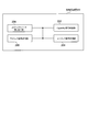
- FIG. 1 is a functional block diagram of a user apparatus UE according to the first embodiment of the present invention.
- FIG. 2 is an example of “information indicating whether or not the user apparatus UE can transmit an uplink signal in a discrete frequency band” generated by the user apparatus UE according to the first embodiment of the present invention.
- FIG. 3 is a functional block diagram of the base station apparatus eNB according to the first embodiment of the present invention.
- the mobile communication system is a system to which, for example, the LTE scheme or the LTE-Advanced scheme is applied.
- the mobile communication system includes a base station apparatus eNB and a user apparatus UE that communicates with the base station apparatus eNB, and the base station apparatus eNB and the user apparatus UE may use the LTE scheme or the LTE-Advanced scheme. Use to communicate.
- the user apparatus UE may be called a mobile terminal.
- Carrier Aggregation may be applied, that is, communication using a plurality of CCs in uplink or downlink. Done.
- CC corresponds to one system carrier in the LTE system. That is, in the LTE scheme, communication using one CC is performed, but in the LTE-Advanced scheme, communication using two or more CCs may be performed.
- PDSCH and PDCCH Physical downlink control channel, physical downlink control channel
- “Operating band” is defined as a set of frequency bands to be operated (Chapter 5.5 of Non-Patent Document 3).
- “Operating band” for example, “Band 1” that is “Operating band” of 2 GHz band, “Band 5” that is “Operating band” of 800 MHz band, and the like are defined.
- the user apparatus UE notifies the base station apparatus eNB of an “Operating band” supported by the own station. That is, the user apparatus UE generally has the capability of performing communication in one or more “Operating bands”, and the “Operating band” having the capability of performing such communication is transmitted to the base station apparatus. Notify eNB.
- the base station apparatus eNB notifies the user apparatus UE in the area of the own station by broadcast information as to which “Operating band” the mobile communication service provided by the own station is provided.
- CC belongs to one of “Operating band” because it corresponds to one system carrier of the LTE system.
- downlink data signals (user data, that is, normal data signals) are transmitted via the PDSCH.
- the user apparatus UE that performs communication using the ID of the user apparatus UE that performs communication using the PDSCH, the transport format information of the downlink data signal (that is, downlink scheduling information), and the PUSCH via the PDCCH.
- the downlink control signal such as the transport format information (i.e., uplink scheduling grant) of the uplink data signal.
- the PDCCH may be referred to as a “downlink L1 / L2 control channel” (Downlink L1 / L2 Control Channel). Further, “downlink scheduling information” and “uplink scheduling grant” may be collectively referred to as “downlink control information (DCI)”.
- DCI downlink control information
- PUSCH and PUCCH that are shared and used by each user apparatus UE are used in the uplink.
- An uplink data signal (user data, that is, a normal data signal) is transmitted via the PUSCH.
- CQI Channel Quality Indicator
- AMCS adaptive modulation / demodulation and coding processing
- delivery confirmation information related to PDSCH via PUCCH Acknowledgement Information
- CSI Channel State Information
- PMI Pre-coding Matrix Indicator
- RI Rank Indicator
- the contents of the acknowledgment information include an acknowledgment (ACK: Acknowledgment) indicating that the downlink signal has been properly received or a negative acknowledgment (NACK: Negative Acknowledgment) indicating that the downlink signal has not been properly received. ).
- ACK Acknowledgment
- NACK Negative Acknowledgment
- the user apparatus UE includes a capability signal generation unit 102, an uplink signal transmission unit 104, and a downlink signal reception unit 106.
- the capability signal generation unit 102, the uplink signal transmission unit 104, and the downlink signal reception unit 106 are connected to each other.
- the Capability signal generation unit 102 is configured to generate a Capability signal that notifies the capability of the user apparatus UE (that is, Capability).
- the Capability signal includes information notifying whether or not the user apparatus UE can simultaneously transmit an uplink signal in a discrete frequency band (that is, a discontinuous frequency band).
- the user equipment UE can simultaneously transmit uplink signals in discrete frequency bands. If the information indicating whether or not is “1” and the user apparatus UE cannot simultaneously transmit an uplink signal in a discrete frequency band, the uplink signal may be simultaneously transmitted in a discrete frequency band. Information indicating whether or not it is possible may be configured to be “0”.
- the information indicating whether or not uplink signals can be transmitted simultaneously in discrete frequency bands includes the case where uplink data signals are transmitted simultaneously in discrete frequency bands and in the discrete frequency bands. It may be set for each of the case where the uplink data signal and the uplink control signal are transmitted simultaneously.
- the capability signal generation unit 102 as shown in FIG. 2, information indicating whether or not uplink signals can be simultaneously transmitted in discrete frequency bands for each frequency band supported by the user apparatus UE. It may be configured to generate a Capability signal including it.
- the frequency band may be the above-mentioned “Operating band (operating band)”.
- Such “Operating band” may be referred to as “Frequency band”.
- the user apparatus UE is configured to generate a Capability signal including information indicating whether or not uplink signals can be transmitted simultaneously in discrete frequency bands for each operation band supported by the user apparatus UE. It may be.
- the frequency band may be more generally a frequency band.
- an uplink signal is simultaneously transmitted in the above-described discrete frequency band to each carrier on which carrier aggregation is performed.
- Information indicating whether or not it can be sent may be notified.
- this 2 Information indicating whether or not uplink signals can be simultaneously transmitted in such discrete frequency bands may be notified to each of the two or more operation bands.
- uplink signals are simultaneously transmitted in the discrete frequency bands to the respective operation bands. If information indicating whether or not it can be transmitted is uplinked simultaneously in a discrete frequency band based on the information related to the operation band to which a plurality of carriers belong when carrier aggregation is performed. It may be determined whether a signal can be transmitted.
- uplink signals can be transmitted simultaneously in a discrete frequency band with respect to all of the operation bands to which a plurality of carriers belong when carrier aggregation is performed. It may be determined that uplink signals can be transmitted simultaneously in different frequency bands.
- the uplink signal transmission unit 104 is configured to transmit an uplink data signal and an uplink control signal to the base station apparatus eNB via PUSCH and PUCCH.
- the uplink signal transmission unit 104 is configured to transmit the capability signal generated by the capability signal generation unit 102 to the base station apparatus eNB.
- the downlink signal reception unit 106 is configured to receive a downlink data signal and a downlink control signal from the base station apparatus eNB via the PDSCH and the PDCCH.
- the base station apparatus eNB includes a capability signal reception unit 202, an uplink signal reception unit 204, an uplink resource allocation unit 206, and a downlink signal transmission unit 208. To do.
- the uplink signal reception unit 204 is configured to receive an uplink data signal and an uplink control signal from the user apparatus UE via the PUSCH or PUCCH.
- the capability signal receiving unit 202 is configured to acquire a capability signal from the uplink signal received by the uplink signal receiving unit 204.
- the Capability signal includes information notifying whether or not the user apparatus UE can simultaneously transmit an uplink signal in a discrete frequency band (that is, a discontinuous frequency band). . Further, as described above, such information may be notified for each frequency band supported by the user apparatus UE.
- the downlink signal transmission unit 208 is configured to transmit a downlink data signal and a downlink control signal to the user apparatus UE via the PDSCH and PDCCH.
- the uplink resource allocation unit 206 determines, for each subframe, a user apparatus UE to which the resource block is allocated among the plurality of user apparatuses UE, and transmits an uplink signal to the user apparatus UE. It is configured to allocate resource blocks.
- the uplink resource allocation unit 206 determines whether or not to transmit an uplink signal in a discontinuous frequency band, based on the capability signal received by the capability signal reception unit 202, and the determination. Based on the result, it is configured to allocate a frequency band (resource block) for transmitting an uplink signal.
- the uplink resource allocation unit 206 is notified that the user apparatus UE can transmit uplink signals simultaneously in discrete frequency bands (that is, discontinuous frequency bands). In other cases, resources are allocated in a continuous frequency band.
- the base station apparatus eNB based on the Capability signal acquired from the user apparatus UE, the capability of the user apparatus and the frequency band in which the user apparatus actually communicates
- a first feature of the present embodiment is a base station apparatus eNB that performs radio communication with a user apparatus UE in a mobile communication system, and simultaneously transmits uplink signals in a discontinuous frequency band allocated from the user apparatus UE.
- a Capability signal receiving unit 202 configured to receive a Capability signal (control signal) for notifying whether or not it has a transmission capability is provided, and the Capability signal is configured to be notified for each operating band. It is a summary.
- the capability signal may be configured to notify whether or not the capability signal has the ability to transmit uplink data signals simultaneously in the allocated discontinuous frequency bands.
- the capability signal is configured to notify whether or not it has an ability to simultaneously transmit an uplink data signal and an uplink control signal in the allocated discontinuous frequency band. May be.
- a second feature of the present embodiment is a user apparatus UE that wirelessly communicates with the base station apparatus eNB within the mobile communication system, and is simultaneously uplinked to the base station apparatus UE in a discontinuous frequency band assigned thereto.
- An uplink signal transmission unit 104 configured to transmit a capability signal for notifying whether or not it has a capability of transmitting a link signal is provided, and the capability signal is configured to be notified for each operation band. It is a summary.
- the capability signal may be configured to notify whether or not the capability signal has the ability to transmit uplink data signals simultaneously in the allocated discontinuous frequency bands.
- the capability signal is configured to notify whether or not it has an ability to simultaneously transmit an uplink data signal and an uplink control signal in the allocated discontinuous frequency band. May be.
- the operations of the user apparatus 100 and the base station apparatus 200 described above may be implemented by hardware, may be implemented by a software module executed by a processor, or may be implemented by a combination of both. .
- the software modules include RAM (Random Access Memory), flash memory, ROM (Read Only Memory), EPROM (Erasable Programmable ROM), EEPROM (Electronically Erasable and Programmable, Removable ROM, Hard Disk, and Removable ROM).
- RAM Random Access Memory
- flash memory ROM (Read Only Memory)
- EPROM Erasable Programmable ROM
- EEPROM Electrically Erasable and Programmable, Removable ROM, Hard Disk, and Removable ROM.
- it may be provided in a storage medium of an arbitrary format such as a CD-ROM.
- the storage medium is connected to the processor so that the processor can read and write information from and to the storage medium. Further, such a storage medium may be integrated in the processor. Such a storage medium and processor may be provided in the ASIC. Such an ASIC may be provided in the user apparatus 100 and the base station apparatus 200. Further, the storage medium and the processor may be provided in the user apparatus 100 and the base station apparatus 200 as discrete components.
- DESCRIPTION OF SYMBOLS 100 ... User apparatus 102 ... Capability signal generation part 104 ... Uplink signal transmission part 106 ... Downlink signal reception part 200 ... Base station apparatus 202 . Capability signal reception part 204 ... Uplink signal reception part 206 ... Uplink resource allocation part 208 ... Downlink signal transmitter
Landscapes
- Engineering & Computer Science (AREA)
- Signal Processing (AREA)
- Computer Networks & Wireless Communication (AREA)
- Databases & Information Systems (AREA)
- Mobile Radio Communication Systems (AREA)
Abstract
Description
「Carrier Aggregation」が行われる場合、異なるCCで、上りリンクデータ信号が送信される。
「Carrier Aggregation」が行われる場合、異なるCCで、上りリンクデータ信号及び上りリンク制御信号が送信される。
シングルキャリア内で、不連続な(すなわち、離散的な)周波数帯域で、上りリンクデータ信号が送信される。
シングルキャリア内で、不連続な周波数帯域において、上りリンクデータ信号及び上りリンク制御信号が送信される。
以下、本発明の第1の実施形態に係る移動通信システムについて、図面を参照しつつ説明する。本実施形態を説明するための全図において、同一機能を有するものは同一符号を用い、繰り返しの説明は省略する。
102…Capability信号生成部
104…上りリンク信号送信部
106…下りリンク信号受信部
200…基地局装置
202…Capability信号受信部
204…上りリンク信号受信部
206…上りリンクリソース割り当て部
208…下りリンク信号送信部
Claims (6)
- 移動通信システム内で、ユーザ装置と無線通信する基地局装置であって、
前記ユーザ装置より、割り当てられた不連続な周波数帯域で同時に上りリンク信号を送信する能力を有するか否かについて通知する制御信号を受信するように構成されている受信部を具備し、
前記制御信号は、運用バンド毎に通知されるように構成されていることを特徴とする基地局装置。 - 前記制御信号は、割り当てられた不連続な周波数帯域で同時に上りリンクデータ信号を送信する能力を有するか否かについて通知するように構成されていることを特徴とする請求項1に記載の基地局装置。
- 前記制御信号は、割り当てられた不連続な周波数帯域で上りリンクデータ信号及び上りリンク制御信号を同時に送信する能力を有するか否かについて通知するように構成されていることを特徴とする請求項1に記載の基地局装置。
- 移動通信システム内で、基地局装置と無線通信するユーザ装置であって、
前記基地局装置に対して、割り当てられた不連続な周波数帯域で同時に上りリンク信号を送信する能力を有するか否かについて通知する制御信号を送信するように構成されている送信部を具備し、
前記制御信号は、運用バンド毎に通知されるように構成されていることを特徴とするユーザ装置。 - 前記制御信号は、割り当てられた不連続な周波数帯域で同時に上りリンクデータ信号を送信する能力を有するか否かについて通知するように構成されていることを特徴とする請求項4に記載のユーザ装置。
- 前記制御信号は、割り当てられた不連続な周波数帯域で上りリンクデータ信号及び上りリンク制御信号を同時に送信する能力を有するか否かについて通知するように構成されていることを特徴とする請求項4に記載のユーザ装置。
Priority Applications (8)
| Application Number | Priority Date | Filing Date | Title |
|---|---|---|---|
| CA2824846A CA2824846C (en) | 2011-02-14 | 2012-02-14 | Base station device and user device |
| RU2013140000/08A RU2580811C2 (ru) | 2011-02-14 | 2012-02-14 | Базовая станция и пользовательское устройство |
| MX2013009390A MX2013009390A (es) | 2011-02-14 | 2012-02-14 | Dispositivo de estacion base y dispositivo de usuario. |
| BR112013020602-0A BR112013020602B1 (pt) | 2011-02-14 | 2012-02-14 | Dispositivo de estação base e dispositivo de usuário |
| CN201280008830.8A CN103370953B (zh) | 2011-02-14 | 2012-02-14 | 基站装置以及用户装置 |
| KR1020137022012A KR101474851B1 (ko) | 2011-02-14 | 2012-02-14 | 기지국장치 및 유저장치 |
| US13/985,356 US9066347B2 (en) | 2011-02-14 | 2012-02-14 | Base station device and user device |
| EP12746566.4A EP2677786B1 (en) | 2011-02-14 | 2012-02-14 | Base station device and user device |
Applications Claiming Priority (2)
| Application Number | Priority Date | Filing Date | Title |
|---|---|---|---|
| JP2011029034A JP5314712B2 (ja) | 2011-02-14 | 2011-02-14 | 基地局装置及びユーザ装置 |
| JP2011-029034 | 2011-02-14 |
Publications (1)
| Publication Number | Publication Date |
|---|---|
| WO2012111638A1 true WO2012111638A1 (ja) | 2012-08-23 |
Family
ID=46672557
Family Applications (1)
| Application Number | Title | Priority Date | Filing Date |
|---|---|---|---|
| PCT/JP2012/053317 WO2012111638A1 (ja) | 2011-02-14 | 2012-02-14 | 基地局装置及びユーザ装置 |
Country Status (10)
| Country | Link |
|---|---|
| US (1) | US9066347B2 (ja) |
| EP (1) | EP2677786B1 (ja) |
| JP (1) | JP5314712B2 (ja) |
| KR (1) | KR101474851B1 (ja) |
| CN (1) | CN103370953B (ja) |
| BR (1) | BR112013020602B1 (ja) |
| CA (1) | CA2824846C (ja) |
| MX (1) | MX2013009390A (ja) |
| RU (1) | RU2580811C2 (ja) |
| WO (1) | WO2012111638A1 (ja) |
Cited By (2)
| Publication number | Priority date | Publication date | Assignee | Title |
|---|---|---|---|---|
| WO2013137392A1 (ja) * | 2012-03-16 | 2013-09-19 | 株式会社エヌ・ティ・ティ・ドコモ | 移動通信方法、無線基地局及び移動局 |
| CN104782201A (zh) * | 2012-11-22 | 2015-07-15 | 富士通株式会社 | 基站装置、无线通信系统、无线通信控制方法、无线通信控制程序 |
Families Citing this family (10)
| Publication number | Priority date | Publication date | Assignee | Title |
|---|---|---|---|---|
| CN103918321B (zh) | 2011-11-01 | 2018-02-02 | 小米香港有限公司 | 带间载波聚合中的功率调节 |
| JP2016040855A (ja) * | 2013-01-16 | 2016-03-24 | シャープ株式会社 | 無線通信システム、基地局装置、端末装置、無線通信方法および集積回路 |
| US11350348B2 (en) * | 2014-03-13 | 2022-05-31 | Intel Corporation | Method for the transfer of radio capability information |
| CN108781445B (zh) * | 2016-03-11 | 2023-06-06 | 日本电气株式会社 | 无线lan系统、无线lan基站、无线lan终端和通信方法 |
| GB2552689A (en) | 2016-08-03 | 2018-02-07 | Nec Corp | Communication system |
| CN109792732A (zh) * | 2016-09-30 | 2019-05-21 | 索尼公司 | 冲突无线电系统的资源分配的方法和装置 |
| WO2018126453A1 (zh) | 2017-01-06 | 2018-07-12 | 广东欧珀移动通信有限公司 | 一种切换方法、基站及终端 |
| US10986613B2 (en) * | 2018-01-19 | 2021-04-20 | Qualcomm Incorporated | Uplink control information (UCI) to resource element (RE) mapping |
| CN110430588B (zh) * | 2019-08-15 | 2022-05-24 | 福建京奥通信技术有限公司 | 基站的自开站方法、介质、设备及装置 |
| CN112153481B (zh) * | 2020-08-24 | 2023-02-17 | 深圳市捷视飞通科技股份有限公司 | 视频数据处理方法、计算机设备和存储介质 |
Citations (1)
| Publication number | Priority date | Publication date | Assignee | Title |
|---|---|---|---|---|
| JP2010263256A (ja) * | 2009-04-28 | 2010-11-18 | Ntt Docomo Inc | 移動局及び移動通信システム |
Family Cites Families (16)
| Publication number | Priority date | Publication date | Assignee | Title |
|---|---|---|---|---|
| RU2388188C2 (ru) * | 2005-08-05 | 2010-04-27 | Нокиа Корпорейшн | Динамическое стробирование восходящего канала управления для повышения пропускной способности |
| CN101127747B (zh) * | 2006-08-14 | 2010-09-08 | 大唐移动通信设备有限公司 | 一种时分双工复用系统中实现频域调度的方法及系统 |
| JP5019966B2 (ja) * | 2007-06-19 | 2012-09-05 | 株式会社エヌ・ティ・ティ・ドコモ | ユーザ装置、基地局装置及びチャネル状態情報通信方法 |
| US20090093255A1 (en) | 2007-10-05 | 2009-04-09 | Qualcomm Incorporated | Adjusting multi-carrier allocation in wireless networks |
| JP5410524B2 (ja) * | 2008-08-08 | 2014-02-05 | ノキア シーメンス ネットワークス オサケユキチュア | 移動局の出力を制御する装置及び方法 |
| KR20130032906A (ko) * | 2009-03-17 | 2013-04-02 | 인터디지탈 패튼 홀딩스, 인크 | 사운딩 레퍼런스 신호(srs) 전송의 전력 제어를 위한 방법 및 장치 |
| US8265575B2 (en) * | 2009-06-16 | 2012-09-11 | Mediatek Inc. | Methods for handling a transmitting process and communication apparatuses utilizing the same |
| KR20110011517A (ko) * | 2009-07-28 | 2011-02-08 | 엘지전자 주식회사 | 다중반송파 지원 광대역 무선 통신 시스템에서의 반송파 관리 절차 수행 방법 및 장치 |
| US9301286B2 (en) * | 2009-08-17 | 2016-03-29 | Lg Electronics Inc. | Method and apparatus for allocating an uplink carrier for transmitting uplink control information in a wireless communication system |
| KR101744667B1 (ko) * | 2009-10-02 | 2017-06-08 | 닛본 덴끼 가부시끼가이샤 | 무선 통신 시스템, 무선 단말, 무선 기지국, 및 무선 통신 방법 |
| CN102123457B (zh) * | 2010-01-11 | 2016-04-13 | 中兴通讯股份有限公司 | 切换方法及终端 |
| US9083501B2 (en) * | 2010-04-05 | 2015-07-14 | Qualcomm Incorporated | Feedback of control information for multiple carriers |
| US20110267948A1 (en) * | 2010-05-03 | 2011-11-03 | Koc Ali T | Techniques for communicating and managing congestion in a wireless network |
| US8780729B2 (en) * | 2010-05-03 | 2014-07-15 | Nokia Corporation | Monitoring pattern separation between component carriers based on user equipment RF layout |
| TW201208436A (en) * | 2010-05-26 | 2012-02-16 | Ind Tech Res Inst | Control channel allocation method, control channel searching method and communication apparatus using the same |
| US8503322B2 (en) * | 2011-02-21 | 2013-08-06 | Motorola Mobility Llc | IQ imbalance image compensation in multi-carrier wireless communication systems |
-
2011
- 2011-02-14 JP JP2011029034A patent/JP5314712B2/ja active Active
-
2012
- 2012-02-14 US US13/985,356 patent/US9066347B2/en active Active
- 2012-02-14 RU RU2013140000/08A patent/RU2580811C2/ru active
- 2012-02-14 EP EP12746566.4A patent/EP2677786B1/en active Active
- 2012-02-14 CA CA2824846A patent/CA2824846C/en active Active
- 2012-02-14 MX MX2013009390A patent/MX2013009390A/es active IP Right Grant
- 2012-02-14 WO PCT/JP2012/053317 patent/WO2012111638A1/ja active Application Filing
- 2012-02-14 KR KR1020137022012A patent/KR101474851B1/ko active IP Right Grant
- 2012-02-14 CN CN201280008830.8A patent/CN103370953B/zh active Active
- 2012-02-14 BR BR112013020602-0A patent/BR112013020602B1/pt active IP Right Grant
Patent Citations (1)
| Publication number | Priority date | Publication date | Assignee | Title |
|---|---|---|---|---|
| JP2010263256A (ja) * | 2009-04-28 | 2010-11-18 | Ntt Docomo Inc | 移動局及び移動通信システム |
Non-Patent Citations (2)
| Title |
|---|
| "Reply LS on Rel-10 UE category", 3GPP TSG RAN WG1 MEETING #63BIS R1-110006, 17 January 2011 (2011-01-17), XP055124511 * |
| See also references of EP2677786A4 * |
Cited By (5)
| Publication number | Priority date | Publication date | Assignee | Title |
|---|---|---|---|---|
| WO2013137392A1 (ja) * | 2012-03-16 | 2013-09-19 | 株式会社エヌ・ティ・ティ・ドコモ | 移動通信方法、無線基地局及び移動局 |
| JP2013197735A (ja) * | 2012-03-16 | 2013-09-30 | Ntt Docomo Inc | 移動通信方法、無線基地局及び移動局 |
| US9668262B2 (en) | 2012-03-16 | 2017-05-30 | Ntt Docomo, Inc. | Mobile communication method, radio base station, and mobile station |
| CN104782201A (zh) * | 2012-11-22 | 2015-07-15 | 富士通株式会社 | 基站装置、无线通信系统、无线通信控制方法、无线通信控制程序 |
| US9826535B2 (en) | 2012-11-22 | 2017-11-21 | Fujitsu Limited | Base station apparatus, radio communication system, and radio communication controlling method |
Also Published As
| Publication number | Publication date |
|---|---|
| KR20130105923A (ko) | 2013-09-26 |
| EP2677786A1 (en) | 2013-12-25 |
| KR101474851B1 (ko) | 2014-12-22 |
| US20130322394A1 (en) | 2013-12-05 |
| CN103370953B (zh) | 2016-01-13 |
| BR112013020602A2 (pt) | 2016-10-18 |
| EP2677786B1 (en) | 2016-06-22 |
| RU2580811C2 (ru) | 2016-04-10 |
| CN103370953A (zh) | 2013-10-23 |
| JP2012169852A (ja) | 2012-09-06 |
| BR112013020602B1 (pt) | 2022-02-22 |
| CA2824846A1 (en) | 2012-08-23 |
| EP2677786A4 (en) | 2014-10-08 |
| US9066347B2 (en) | 2015-06-23 |
| MX2013009390A (es) | 2013-09-26 |
| CA2824846C (en) | 2016-04-12 |
| RU2013140000A (ru) | 2015-03-27 |
| JP5314712B2 (ja) | 2013-10-16 |
Similar Documents
| Publication | Publication Date | Title |
|---|---|---|
| JP5314712B2 (ja) | 基地局装置及びユーザ装置 | |
| EP3525384B1 (en) | Pucch transmission method by wireless device | |
| US9191966B2 (en) | Communication device and method for communicating in a communication mode using a frequency range according to a frame structure | |
| US9426788B2 (en) | Methods and apparatus for transmitting and/or controlling device-to-device discovery signals | |
| CN107612673B (zh) | 用于无线网络的可扩展及可缩放控制信道的方法和设备 | |
| CN101489255B (zh) | 一种上行控制信道的发送方法、装置及系统 | |
| US20120113909A1 (en) | Method of Handling an Uplink Control Channel and Related Communication Device | |
| WO2011065440A1 (ja) | 移動通信システム、基地局装置、移動局装置および通信方法 | |
| EP2542009A1 (en) | Method of handling uplink control information reporting and related communication device | |
| CN108370361A (zh) | 用于时分双工子帧结构中的共用上行链路突发传输的解耦模式 | |
| JP2009260956A (ja) | 無線リソース選択方法、移動局及び無線基地局 | |
| EP3304994B1 (en) | Sending a configuration message and reporting channel information on pucch in pcell and in scell | |
| WO2011078185A1 (ja) | 移動局、無線基地局及び移動通信方法 | |
| US9338786B2 (en) | Reference signal transmitting method, mobile terminal apparatus and radio base station apparatus | |
| WO2011108651A1 (ja) | 無線基地局及び移動通信方法 | |
| JP5227936B2 (ja) | 移動通信方法、移動局及び無線基地局 | |
| WO2014013893A1 (ja) | 移動局 | |
| WO2013172438A1 (ja) | 無線基地局及び移動局 | |
| JP5919035B2 (ja) | 移動局 | |
| WO2009154231A1 (ja) | 基地局装置および移動局装置 | |
| US20120170535A1 (en) | Radio base station and communication control method | |
| KR20110082475A (ko) | 상향링크에서 제어정보와 데이터를 전송하는 전송방법, 상기 전송방법을 결정하는 기지국 | |
| JP2010035234A (ja) | 無線リソース選択方法、移動局及び無線基地局 |
Legal Events
| Date | Code | Title | Description |
|---|---|---|---|
| 121 | Ep: the epo has been informed by wipo that ep was designated in this application |
Ref document number: 12746566 Country of ref document: EP Kind code of ref document: A1 |
|
| ENP | Entry into the national phase |
Ref document number: 2824846 Country of ref document: CA |
|
| NENP | Non-entry into the national phase |
Ref country code: DE |
|
| WWE | Wipo information: entry into national phase |
Ref document number: 13985356 Country of ref document: US Ref document number: MX/A/2013/009390 Country of ref document: MX |
|
| ENP | Entry into the national phase |
Ref document number: 20137022012 Country of ref document: KR Kind code of ref document: A |
|
| WWE | Wipo information: entry into national phase |
Ref document number: 2012746566 Country of ref document: EP |
|
| ENP | Entry into the national phase |
Ref document number: 2013140000 Country of ref document: RU Kind code of ref document: A |
|
| REG | Reference to national code |
Ref country code: BR Ref legal event code: B01A Ref document number: 112013020602 Country of ref document: BR |
|
| ENP | Entry into the national phase |
Ref document number: 112013020602 Country of ref document: BR Kind code of ref document: A2 Effective date: 20130813 |