WO2012111544A1 - エアバッグ及びエアバッグ装置 - Google Patents
エアバッグ及びエアバッグ装置 Download PDFInfo
- Publication number
- WO2012111544A1 WO2012111544A1 PCT/JP2012/053070 JP2012053070W WO2012111544A1 WO 2012111544 A1 WO2012111544 A1 WO 2012111544A1 JP 2012053070 W JP2012053070 W JP 2012053070W WO 2012111544 A1 WO2012111544 A1 WO 2012111544A1
- Authority
- WO
- WIPO (PCT)
- Prior art keywords
- airbag
- strap
- opening
- vent hole
- protrusion
- Prior art date
- Legal status (The legal status is an assumption and is not a legal conclusion. Google has not performed a legal analysis and makes no representation as to the accuracy of the status listed.)
- Ceased
Links
Images



Classifications
-
- B—PERFORMING OPERATIONS; TRANSPORTING
- B60—VEHICLES IN GENERAL
- B60R—VEHICLES, VEHICLE FITTINGS, OR VEHICLE PARTS, NOT OTHERWISE PROVIDED FOR
- B60R21/00—Arrangements or fittings on vehicles for protecting or preventing injuries to occupants or pedestrians in case of accidents or other traffic risks
- B60R21/02—Occupant safety arrangements or fittings, e.g. crash pads
- B60R21/16—Inflatable occupant restraints or confinements designed to inflate upon impact or impending impact, e.g. air bags
- B60R21/23—Inflatable members
- B60R21/239—Inflatable members characterised by their venting means
-
- B—PERFORMING OPERATIONS; TRANSPORTING
- B60—VEHICLES IN GENERAL
- B60R—VEHICLES, VEHICLE FITTINGS, OR VEHICLE PARTS, NOT OTHERWISE PROVIDED FOR
- B60R21/00—Arrangements or fittings on vehicles for protecting or preventing injuries to occupants or pedestrians in case of accidents or other traffic risks
- B60R21/02—Occupant safety arrangements or fittings, e.g. crash pads
- B60R21/16—Inflatable occupant restraints or confinements designed to inflate upon impact or impending impact, e.g. air bags
- B60R21/23—Inflatable members
- B60R21/239—Inflatable members characterised by their venting means
- B60R2021/2395—Inflatable members characterised by their venting means comprising means to control the venting
-
- B—PERFORMING OPERATIONS; TRANSPORTING
- B60—VEHICLES IN GENERAL
- B60R—VEHICLES, VEHICLE FITTINGS, OR VEHICLE PARTS, NOT OTHERWISE PROVIDED FOR
- B60R21/00—Arrangements or fittings on vehicles for protecting or preventing injuries to occupants or pedestrians in case of accidents or other traffic risks
- B60R21/02—Occupant safety arrangements or fittings, e.g. crash pads
- B60R21/16—Inflatable occupant restraints or confinements designed to inflate upon impact or impending impact, e.g. air bags
- B60R21/20—Arrangements for storing inflatable members in their non-use or deflated condition; Arrangement or mounting of air bag modules or components
- B60R21/205—Arrangements for storing inflatable members in their non-use or deflated condition; Arrangement or mounting of air bag modules or components in dashboards
Definitions
- the present invention relates to an airbag and an airbag apparatus, and more particularly to an airbag and an airbag apparatus characterized by means for opening and closing vent holes of the airbag.
- an airbag device for inflating and deploying an airbag in the vehicle in the event of an emergency such as a collision or sudden deceleration to absorb the impact generated on the passenger.
- Such an airbag device includes an airbag device for a driver seat installed in a steering wheel, an airbag device for a passenger seat installed in an instrument panel, a side airbag device installed in a vehicle side or seat, and an upper door portion.
- Various types have been developed and adopted, such as an interior curtain airbag device, a knee airbag device corresponding to an occupant's knee, and a pedestrian airbag device installed under a hood.
- These airbag apparatuses generally include an airbag that is normally folded and inflated and deployed in an emergency, an inflator that supplies gas to the airbag, and a retainer that fixes the airbag and the inflator. Have. Further, an exhaust port called a vent hole may be formed in the outer shell forming the airbag. The vent hole has a function of preventing the internal pressure of the airbag from becoming excessively high, and exhausting the gas in the airbag when the occupant contacts the airbag to alleviate the impact.
- the airbag apparatus in which such a vent hole is formed has a problem that the pressure loss is large because gas is exhausted from the vent hole during the inflation and deployment of the airbag.
- airbag devices for solving such problems for example, those described in Patent Document 1 and Patent Document 2 have already been proposed.
- An airbag device described in Patent Document 1 includes a patch member capable of sealing a vent hole formed on a surface of an airbag, a fixing unit that fixes an end of the patch member to a retainer, and the fixing unit.
- a squib that releases the patch member by releasing the squib, and when the airbag is initially inflated and deployed, the vent hole is sealed with the patch member, and the squib is operated when it is desired to lower the internal pressure of the airbag. Then, the patch member is released to release gas from the vent hole.
- Patent Document 1 also discloses that the patch member is formed in a tube shape, and the tube is drawn into the airbag and fixed to the fixing means.
- the airbag device described in Patent Document 2 includes a convex portion that forms a portion protruding outside in a part of the airbag, a vent hole formed in the convex portion, and one end connected to the convex portion.
- a strap connected at an end to a component part or an attachment part of the airbag, and the vent hole is disposed in a region where the convex part and the airbag overlap when the convex part is pulled by the strap. It is what has been.
- the airbag device described in Patent Document 1 described above has a problem that it is difficult to maintain the airtightness between the patch member and the vent hole. Further, when the patch member is formed in a tube shape, gas cannot be released until the tube is completely opened to the outside of the airbag, so that exhaust responsiveness is dull and it is difficult to control the timing for operating the squib. There was a problem.
- the airbag device described in Patent Document 2 relates to the airbag device serving as the basis of the present invention, and there has been a desire to make it more efficient.
- the present invention was devised in view of such problems, and an object thereof is to provide an air bag and an air bag device that are excellent in airtightness and exhaust responsiveness and are efficient.
- the airbag is normally folded and housed inside the vehicle in a state of being fixed to the retainer, and is inflated and deployed in the passenger compartment in an emergency, and is provided on the surface of the airbag.
- the formed opening, the protruding portion arranged to communicate with the opening, the vent hole formed in the protruding portion, one end connected to the protruding portion, and the other end detachable from the retainer
- the airbag is disposed in a region where the protrusion overlaps with the airbag when the protrusion is pulled, and the strap extends forward toward the opposite side of the occupant when the airbag is inflated and deployed.
- the strap is held to close the vent hole, and when the occupant is small or light, the strap is released.
- the airbag that is normally folded and inflated and deployed in an emergency, an inflator that supplies gas to the airbag, a retainer that fixes the airbag and the inflator, and the airbag
- An airbag device having an airbag cover that covers a bag, wherein the airbag includes an opening formed on a surface of the airbag, a protrusion disposed so as to communicate with the opening, A vent hole formed in the projecting portion, a strap having one end connected to the projecting portion and the other end detachably connected to the retainer, and a slit portion for guiding the strap into the airbag.
- the opening is formed only at the center of the vehicle, and the vent hole is formed when the protrusion is pulled by the strap.
- the protruding portion and the airbag are arranged in a region where the airbag overlaps, and the strap is configured to pull the protruding portion toward the opposite side of the occupant when the airbag is inflated and deployed.
- the strap is held to close the vent hole, and when the occupant is small or light, the strap is released to open the vent hole.
- An airbag device is provided.
- the protrusion includes a substantially triangular first surface and a second surface, and a connecting portion that connects opposite sides of the first surface and the second surface.
- the vent hole is formed on either the first surface or the second surface, a communication port communicating with the opening is formed in the connection portion, and the connection portion is It may be formed by bending to the center and stitching the outer peripheral portions of the first surface and the second surface, and stitching the connecting portion so that the communication port and the opening portion coincide.
- Opening area of the communication port and the opening may be 1.2 times the opening area of the vent hole.
- the communication port and the opening may have a substantially rectangular shape.
- the first surface and the second surface may be configured by a substantially equilateral triangular base fabric.
- the protrusion is formed by sewing the first surface and the second surface, which are sewn from the inside of the base fabric constituting the airbag, to the position of the opening, and outward from the opening. May be.
- the airbag may have a normally open vent hole formed on the center side and the vehicle body side of the vehicle.
- the retainer may include an insertion port that guides the strap to the outside, and a holding unit that releasably holds the strap outside the insertion port.
- the holding means may be configured to hold the strap when the occupant is large or heavy, and to release the strap when the occupant is small or light.
- the protruding portion is disposed only on the center side of the vehicle, so that the protruding portion is interposed between the vehicle body and the airbag when the protruding portion is about to stand up. Will not be caught.
- the vent hole is formed in the protruding portion, the hermeticity of the vent hole can be improved by pressing against the surface of the protruding portion and the airbag.
- the strap can be released at an arbitrary timing, the protruding portion can be raised at an arbitrary timing, and the vent hole can be opened.
- the vent hole is closed, and when the occupant is small or light, the vent hole is opened to adjust the internal pressure of the airbag suitable for the occupant's body shape. be able to. Therefore, it is possible to provide an efficient airbag and the airbag apparatus excellent in airtightness and exhaust responsiveness.
- the protruding portion By forming the protruding portion with the base fabric having the first surface, the second surface and the connecting portion, the protruding portion can be easily formed, and the manufacturing efficiency can be improved.
- the communication port and the opening By forming the communication port and the opening to be larger than the opening area of the vent hole, it is possible to facilitate the flow of gas into the protruding portion and to improve the exhaust efficiency.
- the communication port and the opening By forming the communication port and the opening in a substantially rectangular shape, it is possible to increase the opening width at both ends of the opening, facilitate the flow of gas into the protrusion, and improve the exhaust efficiency. it can.
- first surface and the second surface in a substantially equilateral triangle, tension is evenly applied to the protruding portion, and the strength, air tightness, self-supporting property, exhaust efficiency, etc. of the protruding portion can be improved.
- the projecting portion can be easily formed by sewing the projecting portion inside the airbag and pulling it out from the opening, thereby improving the manufacturing efficiency.
- the gas in the airbag when it collides with the airbag can be exhausted from both the vent hole and the normally open vent hole to improve the exhaust efficiency. Can effectively reduce the impact of the passenger.
- the holding means By arranging the holding means to releasably hold the strap outside the retainer, the strap can be attached to the holding means even after the folded body of the airbag is stored in the retainer, making it easy to assemble the airbag module Can be. Further, part of the holding means can be scattered inside the airbag, or dissolution of the airbag due to the high heat of the holding means can be suppressed.
- the holding and releasing of the strap by the holding means can be controlled at an arbitrary timing, the internal pressure of the airbag can be easily adjusted according to the body shape and weight of the occupant.
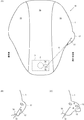
- FIG. 1 is an overall configuration diagram showing an embodiment of an airbag device according to the present invention. It is explanatory drawing of the protrusion part shown in FIG. 1, (A) is a top view of an airbag, (B) has shown the initial stage of the open state of the protrusion part, (C) has shown the completion state of the open state. . It is a plane development view which shows the base fabric structure of the protrusion part shown in FIG. It is a figure which shows the stitching
- FIG. 1 is an overall configuration diagram showing an embodiment of an airbag device according to the present invention. It is explanatory drawing of the protrusion part shown in FIG. 1, (A) is a top view of an airbag, (B) has shown the initial stage of the
- FIG. 2 is a layout view of the airbag device shown in FIG. 1. It is a figure which shows the effect
- FIG. 1 is an overall configuration diagram showing an embodiment of an airbag apparatus according to the present invention.
- 2 is an explanatory view of the protrusion shown in FIG. 1, wherein (A) is a top view of the airbag, (B) is an initial stage of the open state of the protrusion, and (C) is completion of the open state. State.
- the airbag device 10 As shown in FIGS. 1 and 2, the airbag device 10 according to the embodiment of the present invention is folded in a normal state and inflated and deployed in an emergency, and supplies gas to the airbag 1.
- the air bag 1 includes an inflator 2, a retainer 3 that fixes the air bag 1 and the inflator 2, and an air bag cover 4 that covers the air bag 1.
- the air bag 1 has an opening 11 formed on the surface of the air bag 1.
- a protrusion 12 arranged to communicate with the opening 11, a vent hole 13 formed in the protrusion 12, one end connected to the protrusion 12, and the other end detachably connected to the retainer 3.
- the strap 14 and the slit 15 for guiding the strap 14 to the inside of the airbag 1 are provided.
- the opening 11 is formed only on the center side of the vehicle, and the vent hole 13 is
- the protrusion 12 and the airbag 1 are arranged in a region where the protrusion 12 overlaps when the protrusion 12 is pulled by the top 14, and the strap 14 protrudes toward the opposite side of the occupant when the airbag 1 is inflated and deployed.
- the strap 14 is held and the vent hole 13 is closed.
- the strap 14 is released and the vent hole 13 is released. Is configured to be in an open state.
- the airbag apparatus 10 shown in FIG. 1 is an airbag apparatus for a passenger seat, and is stored by being fixed to an instrument panel 5 disposed in front of the passenger seat.
- the air bag 1 starts to inflate and deploy when gas is supplied to the inside by the operation of the inflator 2, breaks through the door portion 41 of the air bag cover 4, and is released into the vehicle interior while contacting the front window W. It is inflated and deployed in front of the passenger.
- the inflator 2 is a gas generator that generates gas to be supplied to the airbag 1 and has, for example, a substantially disk-shaped outer shape.
- FIG. 1 shows the case of a disk-type inflator 2, a cylinder-type inflator 2 having a substantially cylindrical outer shape may be used.
- the inflator 2 is connected to an ECU (electronic control unit) (not shown) and is controlled based on measurement values of an acceleration sensor or the like. When the ECU senses or predicts a vehicle collision or sudden deceleration, the inflator 2 is ignited by the ignition current from the ECU, burns the chemical stored in the inflator 2 to generate gas, and the gas is supplied to the airbag 1. Supply.
- the retainer 3 is supported by the airbag cover 4 by hooking a hook 31 into an engagement hole formed in the leg portion 42 of the airbag cover 4, for example. Further, the retainer 3 is secured to the vehicle structure in the instrument panel 5 by a fixing bracket 32. Furthermore, the retainer 3 includes an insertion port 33 that guides the strap 14 to the outside, and a holding unit 34 that releasably holds the strap 14 outside the insertion port 33.
- the holding unit 34 may have any configuration as long as it holds the strap 14 releasably at an arbitrary timing.
- the holding unit 34 has, for example, a configuration using a squib or the like, and holds, releases, or cuts the strap 14 according to a command from the ECU.
- the strap 14 can be attached to the holding means 34 even after the folded body of the airbag 1 is stored in the retainer 3, and the airbag module can be assembled. Can be easily. Furthermore, a part of the holding means 34 can be scattered inside the airbag 1 or the dissolution of the airbag 1 due to the high heat of the holding means 34 can be suppressed.
- the airbag 1 is, for example, a pair of side panels 1a disposed on a side surface portion of the airbag 1 at the time of inflation and deployment, and a center panel disposed at the center of the airbag 1 and connecting the pair of side panels 1a. 1b. Since this airbag 1 is comprised by three base fabrics, it has a 3 piece structure.
- the center panel 1b constitutes a surface that comes into contact with an occupant when the airbag 1 is inflated and deployed.
- a normally open vent hole 16 is formed in the side panel 1a. That is, the airbag 1 has a normally open vent hole 16 formed on the center side and the vehicle body side of the vehicle. By forming the normally open vent hole 16, the gas in the airbag 1 when colliding with the airbag 1 can be exhausted from both the vent hole 13 and the normally open vent hole 16 to the outside. Exhaust efficiency can be improved, and passenger impact can be effectively mitigated.
- the opening 11 is formed in a side panel 1a disposed on the center side of the vehicle when the airbag 1 is inflated and deployed, and the side panel 1a disposed on the vehicle body side (door side) when the airbag 1 is inflated and deployed. Is not formed.
- a protrusion 12 is stitched to the opening 11 and the protrusion 12 is configured to be able to stand on the surface of the airbag 1 (side panel 1a).
- a string-like strap 14 is connected to the protrusion 12, and the protrusion 12 is brought into close contact with the surface of the airbag 1 by holding or releasing the strap 14 when the airbag 1 is inflated and deployed. Or stand up.
- the strap 14 is drawn into the airbag 1 from a slit portion 15 formed in the airbag 1, and is connected so that tension can be generated between the protruding portion 12 and the holding means 34.
- the strap 14 is made of, for example, a base fabric that is the same material as the airbag 1.
- the slit portion 15 may be a cut portion or a slot-shaped opening.
- FIG. 3 is a plan development view showing a base fabric configuration of the protruding portion shown in FIG. 1.
- the protruding portion 12 includes a first surface 121 and a second surface 122 that are substantially equilateral triangles, and a connecting portion 123 that connects opposite sides of the first surface 121 and the second surface 122.
- the vent hole 13 is formed in the first surface 121
- the communication port 124 communicating with the opening 11 is formed in the connection portion 123
- the center line L of the connection portion 123 is formed.
- the outer peripheral portions of the first surface 121 and the second surface 122 are sewn, and the connecting portion 123 is sewn so that the communication port 124 and the opening portion 11 coincide with each other.
- the first surface 121 and the second surface 122 have an apex angle ⁇ and a base angle ⁇ of about 60 degrees, respectively, and are formed in the same size. Moreover, the top part may be formed roundly.
- the tension is evenly applied to the protruding portion 12, and the strength, air tightness, self-supporting property, and exhaust of the protruding portion 12 are provided. Efficiency etc. can be improved.
- the first surface 121 and the second surface 122 may be configured by a substantially isosceles triangular base fabric, or the first surface 121 and the second surface 122 may be configured to have different sizes. Good.
- a suture line s1 is disposed on the outer periphery of the two sides forming the apex angle ⁇ of the first surface 121 and the second surface 122.
- the protrusion 12 forms a bag body by overlapping the first surface 121 and the second surface 122 and stitching along the stitching line s1.
- the connecting portion 123 is a portion that connects the first surface 121 and the second surface 122 and is sewn to the side panel 1 a of the airbag 1 so that the communication port 124 communicates with the opening 11 of the airbag 1. In this way, by configuring the protruding portion 12 with a single base fabric, the number of parts of the protruding portion 12 can be reduced, and stitching and the like can be easily performed.
- the communication port 124 has substantially the same shape as the opening 11, and the communication port 124 and the opening 11 have a substantially rectangular shape.
- the opening width x at both ends of the communication port 124 and the opening portion 11 can be formed large, and gas can easily flow into the protruding portion 12. can, it is possible to reduce the choke of gas flowing into the projecting portion 12, it is possible to improve the exhaust efficiency.
- the opening area of the communication port 124 and the opening part 11 has a magnitude
- the communication port 124 is disposed so as to coincide with the opening portion 11, and the connection portion 123 and the side panel 1 a are stitched along the suture line s 2 surrounding the communication port 124.
- both end portions of the connecting portion 123 have a rectangular cutout portion 125, and the cutout portion 125 has a pair of side portions 125a and a bottom portion 125b.
- the length of the base 125b is formed to be twice as large as the length d of one side 125a (2d). Accordingly, when the connecting portion 123 is bent along the fold line M passing through the corners of the side portion 125a and the bottom portion 125b, the pair of side portions 125a and the bottom portion 125b coincide with each other.
- the suture line s3 formed on the outer periphery of the notch 125 also coincides, and the suture line s3 is arranged in a straight line.
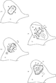
- FIG. 4 is a diagram illustrating a method of stitching the protruding portion illustrated in FIG. 1, (A) is a reinforcing patch stitching step, (B) is a communication port stitching step, (C) is a connecting portion stitching step, (D) is an outer peripheral portion stitching step.
- A is a reinforcing patch stitching step
- B is a communication port stitching step
- C is a connecting portion stitching step
- D is an outer peripheral portion stitching step.
- a two-dot chain line indicates a suture line.
- FIG. 4 (A) shows the reinforcing patch stitching step.
- the side panel 1a on the side having the opening 11 is prepared, and the side panel 1a on which the inner surface of the airbag 1 is formed is face-up. At this stage, the opening 11 may not be formed in the side panel 1a.
- a reinforcing patch 126 having a shape larger than that of the opening 11 is prepared, arranged at a position where the opening 11 can be covered, and sutured to the side panel 1a along the suture line s4.
- Reinforcing patch 126 is a part for reinforcing the likely root portion of the projection 12 takes the load.
- a plurality of pin holes 126 a are formed in the portion where the opening 11 is disposed in the central portion of the reinforcing patch 126.
- the pin hole 126a is inserted with a pin for positioning when the reinforcing patch 126 and the protruding portion 12 are stitched.
- FIG. 4 (B) shows the communication port stitching process.
- a base fabric constituting the protruding portion 12 shown in FIG. 3 is prepared, and the communication port 124 is made to coincide with the opening portion 11 and is sewn along the stitching line s2.
- a plurality of pin holes corresponding to the pin holes 126a shown in FIG. 4A are formed without forming the communication port 124 in the base fabric constituting the projecting portion 12, and the pin opening 11 and the communication port 124 to be formed by securing to match the hole is kept to match.
- the side panel 1a, the reinforcing patch 126, and the protruding portion 12 are cut, and the opening 11 and the communication are communicated.
- the mouth 124 may be formed.
- the step of cutting the side panel 1a, the reinforcing patch 126, and the protruding portion 12 may be performed in advance before sewing, and the side panel 1a, the reinforcing patch 126, and the protruding portion may be performed by a method other than positioning pins or positioning pins.
- the base fabric constituting the portion 12 may be fixed and stitched.
- FIG. 4C shows the connecting portion stitching step.
- both ends of the connecting portion 123 are folded along the folding line M in the direction of the arrow in the figure.
- the side part 125a and the base part 125b in the notch part 125 of the connection part 123 shown in FIG. 3 are made to correspond.
- both end portions of the projecting portion 12 are sewn along the straight stitching line s3 at both end portions (the side portion 125a and the bottom portion 125b) of the connecting portion 123. Is sealed.
- FIG. 4C for the convenience of explanation, the illustration of a part of the first surface 121 and the second surface 122 is omitted.
- FIG. 4 (D) shows the outer periphery stitching step.
- the first surface 121 and the second surface 122 shown in FIG. 3 are overlapped and stitched along the stitching line s1.
- the outer peripheral portion of the protruding portion 12 is sealed to form a bag.
- the strap 14 can be easily connected to the protruding portion 12 by sandwiching one end of the strap 14 at the top of the protruding portion 12 and sewing together.
- the strap 14 may be sewn and connected to the flat portion of either the first surface 121 or the second surface 122, or may be sandwiched and sewn to a portion other than the top of the protruding portion 12. Also good.
- the state shown in FIG. 4D is a state in which the protruding portion 12 is formed on the inner surface side of the side panel 1a. Therefore, finally, it is necessary to pull out from the opening 11 to the outer surface side of the side panel 1a. That is, the protrusion 12 is stitched from the inside of the base fabric (side panel 1 a) constituting the airbag 1 to the position of the opening 11, and the stitched first surface 121 and second surface 122 are outside the opening 11. Formed by pulling on. Through this process, the projecting portion 12 is disposed outside the airbag 1 as shown in FIG. Note that the above-described stitching method of the protruding portion 12 is merely an example, and the step of stitching the protruding portion 12 on the outer surface side of the side panel 1a and turning it over may be omitted.
- FIG. 5 is a layout view of the airbag apparatus shown in FIG.
- symbol is attached
- the airbag apparatus 10 shown in FIG. 1 is disposed on the passenger seat 201 side of the vehicle 20.
- the airbag device 10 is disposed and stored in the instrument panel 5 positioned in front of the passenger 202 seated in the passenger seat 201 of the vehicle 20.
- the protrusion part 12 formed in the airbag 1 is arrange
- the protruding portion 12 only on the center portion side of the vehicle 20 it is possible to easily secure a sufficient space for the protruding portion 12 to stand, and the protruding portion 12 is formed between the vehicle body and the airbag 1.
- the airbag 12 in the driver's seat 204 and the rear seat 205 may be formed with the protruding portion 12 disposed only on the center portion side of the vehicle 20.
- the vehicle 20 shown in FIG. 5 is a left-hand drive vehicle, but the airbag device 10 according to the present embodiment can also be applied to a right-hand drive vehicle.
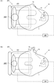
- FIG. 6 is a figure which shows the effect
- the weight is generally light and the inertia force generated when the vehicle 20 is suddenly decelerated is small. Therefore, it is necessary to reduce the internal pressure of the airbag 1 so that the occupant 202 can be received softly. Therefore, the strap 14 is released by the holding means 34, and the protruding portion 12 is left open.
- the projecting portion 12 is opened, the gas supplied from the inflator 2 to the airbag 1 is gas from both the normally open vent hole 16 (see FIG. 1) and the vent hole 13 formed in the projecting portion 12. It is exhausted and the amount of exhaust can be increased. Therefore, the internal pressure of the airbag 1 can be easily lowered.
- a seat load sensor 207 connected to an ECU (electronic control unit) 206, for example.
- the seat load sensor 207 is disposed, for example, in the seat of the passenger seat 201 where an occupant is seated. Further, instead of the seat load sensor 207, the body shape of the occupant 202 may be determined by image processing means using a seat position sensor or a CCD camera or the like disposed in the vehicle.
- the seat load sensor 207 determines whether the occupant 202 is large, small, heavy or light, and the result is sent to the ECU 206 as occupant physique information.
- the occupant physique information is information that, for example, sets a weight threshold value, recognizes it as a large figure when it is heavier than the threshold, and recognizes it as a small figure when it is lighter than the threshold.
- the ECU 206 senses or predicts a collision or sudden deceleration of the vehicle 20, the ECU 206 controls the holding means 34 based on the occupant physique information and controls the holding or releasing of the strap 14. That is, the holding means 34 is configured to hold the strap 14 when the occupant 202 is large or heavy, and to release the strap 14 when the occupant 202 is small or light.
- the airbag 1 may have a structure other than the three-piece structure (for example, a two-piece structure or a four-piece structure or more). It does not depart from the gist of the present invention, for example, a rectifying means for restricting air flow, a tether for restricting the shape of the airbag 1, or a holding means 34 may be arranged inside the retainer. Of course, various changes can be made within the range.
Landscapes
- Engineering & Computer Science (AREA)
- Mechanical Engineering (AREA)
- Air Bags (AREA)
Abstract
気密性及び排気応答性に優れるとともに効率的なエアバッグ及びエアバッグ装置を提供する。 エアバッグ1は、エアバッグ1の表面に形成された開口部11と、開口部11と連通するように配置された突出部12と、突出部12に形成されたベントホール13と、一端が突出部12に接続され他端がリテーナ3に接続されたストラップ14と、ストラップ14をエアバッグ1の内部に案内するスリット部15と、を有し、開口部11は、車両の中心部側にのみ形成されており、ベントホール13は、ストラップ14で突出部12を引っ張った時に突出部12とエアバッグ1とが重なり合う領域に配置されており、ストラップ14は、エアバッグ1の膨張展開時における乗員と反対側に向かって突出部12を引っ張るように構成されている。
Description
本発明は、エアバッグ及びエアバッグ装置に関し、特に、エアバッグのベントホールの開閉手段に特徴を有するエアバッグ及びエアバッグ装置に関する。
自動車等の車両には、衝突時や急減速時等の緊急時にエアバッグを車内で膨張展開させて乗員に生ずる衝撃を吸収するためのエアバッグ装置が搭載されることが一般的になっている。かかるエアバッグ装置には、ステアリングに内装された運転席用エアバッグ装置、インストルメントパネルに内装された助手席用エアバッグ装置、車両側面部又はシートに内装されたサイドエアバッグ装置、ドア上部に内装されたカーテンエアバッグ装置、乗員の膝部に対応したニーエアバッグ装置、フード下に内装された歩行者用エアバッグ装置等、種々のタイプが開発・採用されている。
これらのエアバッグ装置は、一般に、通常時は折り畳まれており緊急時に膨張展開されるエアバッグと、該エアバッグにガスを供給するインフレータと、前記エアバッグ及び前記インフレータを固定するリテーナと、を有する。また、エアバッグを形成する外殻には、ベントホールと呼ばれる排気口が形成されている場合もある。このベントホールは、エアバッグの内圧が高くなり過ぎないようにしたり、乗員がエアバッグに接触した際にエアバッグ内のガスを排気して衝撃を緩和したりする機能を有する。
かかるベントホールが形成されたエアバッグ装置では、エアバッグの膨張展開中にベントホールからガスが排気されてしまうため圧力損失が大きいという問題があった。かかる問題点を解決するためのエアバッグ装置には、例えば、特許文献1及び特許文献2に記載されたものが既に提案されている。
特許文献1に記載されたエアバッグ装置は、エアバッグの表面に形成されたベントホールを封止可能なパッチ部材と、該パッチ部材の端部をリテーナに固定する固定手段と、該固定手段を解除して前記パッチ部材を解放するスクイブと、を有し、前記エアバッグの膨張展開初期は前記ベントホールを前記パッチ部材で封止し、前記エアバッグの内圧を下げたいときに前記スクイブを作動させて前記パッチ部材を解放し、前記ベントホールからガスを放出させるようにしたものである。また、特許文献1には、前記パッチ部材をチューブ状に形成し、該チューブを前記エアバッグ内に引き込んで前記固定手段に固定するようにしたものも開示されている。
特許文献2に記載されたエアバッグ装置は、エアバッグの一部に外部に突出した部分を形成する凸部と、該凸部に形成されたベントホールと、一端が前記凸部に接続され他端が前記エアバッグの構成部品又は取付部品に接続されたストラップと、を備え、前記ベントホールは、前記ストラップで前記凸部を引っ張った時に、前記凸部と前記エアバッグとが重なり合う領域に配置されているものである。
しかしながら、上述した特許文献1に記載されたエアバッグ装置では、パッチ部材とベントホールとの間の気密性を維持することが難しいという問題があった。また、パッチ部材をチューブ状にした場合には、チューブがエアバッグの外部に完全に開放されるまでガスを放出することができないため、排気応答性が鈍く、スクイブを作動させるタイミングの制御が難しいという問題があった。
また、特許文献2に記載されたエアバッグ装置は、本発明の基礎となるエアバッグ装置に関するものであり、より効率的にしたいという要望があった。
本発明はかかる問題点に鑑み創案されたものであり、気密性及び排気応答性に優れるとともに効率的なエアバッグ及びエアバッグ装置を提供することを目的とする。
本発明によれば、リテーナに固定された状態で、通常時は折り畳まれて車両の内部に収納されており、緊急時に車室内に膨張展開されるエアバッグであって、前記エアバッグの表面に形成された開口部と、該開口部と連通するように配置された突出部と、該突出部に形成されたベントホールと、一端が前記突出部に接続され他端が前記リテーナに着脱可能に接続されたストラップと、該ストラップを前記エアバッグの内部に案内するスリット部と、を有し、前記開口部は、前記車両の中心部側にのみ形成されており、前記ベントホールは、前記ストラップで前記突出部を引っ張った時に前記突出部と前記エアバッグとが重なり合う領域に配置されており、前記ストラップは、前記エアバッグの膨張展開時における乗員と反対側に向かって前記突出部を引っ張るように構成されており、前記乗員が大柄又は体重が重い場合に前記ストラップを保持して前記ベントホールを閉状態とし、前記乗員が小柄又は体重が軽い場合に前記ストラップを解放して前記ベントホールを開状態とした、ことを特徴とするエアバッグが提供される。
また、本発明によれば、通常時は折り畳まれており緊急時に膨張展開されるエアバッグと、該エアバッグにガスを供給するインフレータと、前記エアバッグ及び前記インフレータを固定するリテーナと、前記エアバッグを被覆するエアバッグカバーと、を有するエアバッグ装置において、前記エアバッグは、前記エアバッグの表面に形成された開口部と、該開口部と連通するように配置された突出部と、該突出部に形成されたベントホールと、一端が前記突出部に接続され他端が前記リテーナに着脱可能に接続されたストラップと、該ストラップを前記エアバッグの内部に案内するスリット部と、を有し、前記開口部は、前記車両の中心部側にのみ形成されており、前記ベントホールは、前記ストラップで前記突出部を引っ張った時に前記突出部と前記エアバッグとが重なり合う領域に配置されており、前記ストラップは、前記エアバッグの膨張展開時における乗員と反対側に向かって前記突出部を引っ張るように構成されており、前記乗員が大柄又は体重が重い場合に前記ストラップを保持して前記ベントホールを閉状態とし、前記乗員が小柄又は体重が軽い場合に前記ストラップを解放して前記ベントホールを開状態とした、ことを特徴とするエアバッグ装置が提供される。
上述したエアバッグ及びエアバッグ装置において、前記突出部は、略三角形の第一面及び第二面と、該第一面及び該第二面の対峙する辺を連結する連結部と、を有する一枚の基布により構成されており、前記第一面又は前記第二面のいずれかに前記ベントホールが形成され、前記連結部に前記開口部と連通する連通口が形成され、前記連結部を中心に折り曲げて前記第一面と前記第二面との外周部を縫合し、前記連結部を前記連通口と前記開口部とが一致するように縫合することによって形成されていてもよい。
前記連通口及び前記開口部の開口面積は、前記ベントホールの開口面積の1.2倍以上であってもよい。また、前記連通口及び前記開口部は略矩形を有していてもよい。また、前記第一面及び前記第二面は、略正三角形の基布により構成されていてもよい。さらに、前記突出部は、前記エアバッグを構成する基布の内側から前記開口部の位置に縫合され、縫合された前記第一面及び前記第二面を前記開口部から外側に引き出すことによって形成されていてもよい。
前記エアバッグは、前記車両の中心側及び車体側に形成された常開型ベントホールを有していてもよい。
前記エアバッグ装置において、前記リテーナは、前記ストラップを外部に案内する挿通口と、該挿通口の外部で前記ストラップを解放可能に保持する保持手段と、を有していてもよい。また、前記保持手段は、乗員が大柄又は体重が重い場合に前記ストラップを保持し、乗員が小柄又は体重が軽い場合に前記ストラップを解放するように構成されていてもよい。
上述した本発明に係るエアバッグ及びエアバッグ装置によれば、突出部を車両の中心部側にのみ配置したことにより、突出部が起立しようとした際に車体とエアバッグとの間に突出部が挟まれてしまうことがない。また、ベントホールを突出部に形成したことにより、突出部及びエアバッグの表面に押し付けることによってベントホールの密閉性を向上させることができる。また、ストラップを着脱可能にリテーナに接続することにより、任意のタイミングでストラップを解放することができ、任意のタイミングで突出部を起立させることができ、ベントホールを開放させることができる。特に、乗員が大柄又は体重が重い場合にベントホールを閉状態とし、乗員が小柄又は体重が軽い場合にベントホールを開状態とすることにより、乗員の体型に適したエアバッグの内圧に調整することができる。したがって、気密性及び排気応答性に優れるとともに効率的なエアバッグ及びエアバッグ装置を提供することができる。
第一面、第二面及び連結部を有する基布により突出部を構成することによって、容易に突出部を形成することができ、製造効率を向上させることができる。
連通口及び開口部をベントホールの開口面積よりも大きく形成することにより、突出部にガスを流入させやすくすることができ、排気効率を向上させることができる。
連通口及び開口部を略矩形に形成することにより、開口部の両端部における開口幅を大きく形成することができ、突出部にガスを流入させやすくすることができ、排気効率を向上させることができる。
第一面及び第二面を略正三角形に形成することにより、突出部に均等に張力が付与され、突出部の強度、気密性、自立性、排気効率等を向上させることができる。
突出部をエアバッグの内側に縫合して開口部から外部に引き出すことにより、容易に突出部を形成することができ、製造効率を向上させることができる。
常開型ベントホールを形成することにより、エアバッグに衝突した際におけるエアバッグ内のガスをベントホールと常開型ベントホールとの両方から外部に排気することができ、排気効率を向上させることができ、効果的に乗員の衝撃を緩和することができる。
リテーナの外部にストラップを解放可能に保持する保持手段を配置したことにより、エアバッグの折り畳み体をリテーナに収納した後からでも、ストラップを保持手段に取り付けることができ、エアバッグモジュールの組立を容易にすることができる。また、保持手段の一部がエアバッグの内部に飛散したり、保持手段の高熱によるエアバッグの溶解を抑制したりすることができる。
保持手段によるストラップの保持及び解放を、任意のタイミングで制御できるようにしたことにより、乗員の体型や体重に応じてエアバッグの内圧を容易に調整することができる。
以下、本発明の実施形態について図1~図6を用いて説明する。ここで、図1は、本発明に係るエアバッグ装置の実施形態を示す全体構成図である。また、図2は、図1に示した突出部の説明図であり、(A)はエアバッグの上面図、(B)は突出部の開状態の初期段階、(C)は開状態の完了状態、を示している。
本発明の実施形態に係るエアバッグ装置10は、図1及び図2に示したように、通常時は折り畳まれており緊急時に膨張展開されるエアバッグ1と、エアバッグ1にガスを供給するインフレータ2と、エアバッグ1及びインフレータ2を固定するリテーナ3と、エアバッグ1を被覆するエアバッグカバー4と、を有し、エアバッグ1は、エアバッグ1の表面に形成された開口部11と、開口部11と連通するように配置された突出部12と、突出部12に形成されたベントホール13と、一端が突出部12に接続され他端がリテーナ3に着脱可能に接続されたストラップ14と、ストラップ14をエアバッグ1の内部に案内するスリット部15と、を有し、開口部11は、車両の中心部側にのみ形成されており、ベントホール13は、ストラップ14で突出部12を引っ張った時に突出部12とエアバッグ1とが重なり合う領域に配置されており、ストラップ14は、エアバッグ1の膨張展開時における乗員と反対側に向かって突出部12を引っ張るように構成されており、乗員が大柄又は体重が重い場合にストラップ14を保持してベントホール13を閉状態とし、乗員が小柄又は体重が軽い場合にストラップ14を解放してベントホール13を開状態とするように構成されている。
図1に示したエアバッグ装置10は、助手席用エアバッグ装置であり、助手席の前面に配置されたインストルメントパネル5に固定されることによって格納される。エアバッグ1は、インフレータ2の作動により内部にガスが供給されると膨張展開を開始し、エアバッグカバー4の扉部41を突き破って車室内に放出され、フロントウィンドウWに接触しながら車室内の乗員の前方に膨張展開される。
前記インフレータ2は、エアバッグ1に供給されるガスを発生させるガス発生器であり、例えば、略円板形状の外形をなしている。図1では、ディスク型のインフレータ2の場合を図示しているが、略円柱形状の外形をなしたシリンダ型のインフレータ2を使用してもよい。インフレータ2は、図示しないECU(電子制御ユニット)に接続されており、加速度センサ等の計測値に基づいて制御される。ECUが車両の衝突や急減速を感知又は予測すると、インフレータ2はECUからの点火電流により点火され、インフレータ2の内部に格納された薬剤を燃焼させてガスを発生させ、エアバッグ1にガスを供給する。
前記リテーナ3は、例えば、エアバッグカバー4の脚部42に形成された係合孔にフック31を引っ掛けることによってエアバッグカバー4に支持される。また、リテーナ3は、固定金具32によりインストルメントパネル5内の車内構造物に固定される。さらに、リテーナ3は、ストラップ14を外部に案内する挿通口33と、挿通口33の外部でストラップ14を解放可能に保持する保持手段34と、を有する。保持手段34は、ストラップ14を任意のタイミングで解放可能に保持する手段であれば、どのような構成であってもよい。保持手段34は、例えば、スクイブ等を使用した構成を有し、ECUからの指令によりストラップ14を保持したり解放したり切断したりする。また、リテーナ3の外部に保持手段34を配置することにより、エアバッグ1の折り畳み体をリテーナ3に収納した後からでも、ストラップ14を保持手段34に取り付けることができ、エアバッグモジュールの組立を容易にすることができる。さらに、保持手段34の一部がエアバッグ1の内部に飛散したり、保持手段34の高熱によるエアバッグ1の溶解を抑制したりすることができる。
前記エアバッグ1は、例えば、膨張展開時におけるエアバッグ1の側面部に配置される一対のサイドパネル1aと、エアバッグ1の中央部に配置されるとともに一対のサイドパネル1aを連結するセンターパネル1bと、により構成される。かかるエアバッグ1は、三つの基布により構成されることから、3ピース構造を有する。センターパネル1bは、エアバッグ1の膨張展開時に乗員と接触する面を構成する。サイドパネル1aには、常開型ベントホール16が形成されている。すなわち、エアバッグ1は、車両の中心側及び車体側に形成された常開型ベントホール16を有する。かかる常開型ベントホール16を形成することにより、エアバッグ1に衝突した際におけるエアバッグ1内のガスをベントホール13と常開型ベントホール16との両方から外部に排気することができ、排気効率を向上させることができ、効果的に乗員の衝撃を緩和することができる。
前記開口部11は、エアバッグ1の膨張展開時に車両の中心側に配置されるサイドパネル1aに形成されており、エアバッグ1の膨張展開時に車体側(ドア側)に配置されるサイドパネル1aには形成されていない。かかる開口部11には、突出部12が縫合されており、突出部12はエアバッグ1(サイドパネル1a)の表面で起立可能に構成されている。
また、突出部12には紐状のストラップ14が接続されており、エアバッグ1の膨張展開時にストラップ14を保持したり解放したりすることによって、突出部12をエアバッグ1の表面に密着させたり、起立させたりすることができる。ストラップ14は、エアバッグ1に形成されたスリット部15からエアバッグ1の内部に引き込まれており、突出部12と保持手段34との間で張力を生じさせることができるように繋いでいる。ストラップ14は、例えば、エアバッグ1と同様の素材である基布により構成される。スリット部15は、切り込み部であってもよいし、スロット状の開口部であってもよい。
図2(A)に示したように、保持手段34でストラップ14を保持している場合には、突出部12はエアバッグ1の表面に押し付けられる。この押し付けられた部分にベントホール13が形成されている。したがって、ストラップ14を保持した場合には、ベントホール13は閉状態になっており、外部にガスを排気しないように構成されている。
保持手段34を作動させてストラップ14を解放した場合には、図2(B)に示したように、ストラップ14の張力が低下することから、突出部12の内部に流入するガスにより突出部12はエアバッグ1の表面上で起立しようとする。したがって、ベントホール13からガスが徐々に排気される。最終的に、図2(C)に示したように、突出部12は、エアバッグ1の表面上で起立し、ベントホール13は完全に開放され、効率よくガスを外部に排気する。このとき、ベントホール13は、乗員と反対側(フロントウィンドウW側)に形成されていることから、ベントホール13から排気されるガスが乗員に吹きかかることがない。
ここで、突出部12の構成について、図3を参照しつつ説明する。図3は、図1に示した突出部の基布構成を示す平面展開図である。
突出部12は、例えば、図3に示したように、略正三角形の第一面121及び第二面122と、第一面121及び第二面122の対峙する辺を連結する連結部123と、を有する一枚の基布により構成されており、第一面121にベントホール13が形成され、連結部123に開口部11と連通する連通口124が形成され、連結部123の中心線Lに沿って折り曲げて第一面121と第二面122との外周部を縫合し、連結部123を連通口124と開口部11とが一致するように縫合することによって形成される。
第一面121及び第二面122は、それぞれ約60度の頂角φ及び底角θを有し、同じ大きさに形成されている。また、その頂部は丸く形成されていてもよい。第一面121及び第二面122を同じ大きさの略正三角形の基布により構成することにより、突出部12に均等に張力が付与され、突出部12の強度、気密性、自立性、排気効率等を向上させることができる。勿論、第一面121及び第二面122は、略二等辺三角形の基布により構成されていてもよいし、第一面121及び第二面122の大きさが異なるように構成されていてもよい。また、第一面121及び第二面122の頂角φを形成する二辺の外周部には縫合線s1が配置されている。突出部12は、第一面121及び第二面122を重ね合わせて縫合線s1に沿って縫合されることによって袋体を形成する。
連結部123は、第一面121及び第二面122を連結するとともに、連通口124がエアバッグ1の開口部11と連通するようにエアバッグ1のサイドパネル1aに縫合される部分である。このように、突出部12を一枚の基布により構成することにより、突出部12の部品点数を低減することができ、縫合等の製造も容易に行うことができる。
連通口124は、実質的に開口部11と同じ形状を有しており、連通口124及び開口部11は略矩形を有している。連通口124及び開口部11を略矩形に形成することにより、連通口124及び開口部11の両端部における開口幅xを大きく形成することができ、突出部12にガスを流入させやすくすることができ、突出部12に流入するガスのチョークを低減することができ、排気効率を向上させることができる。
また、連通口124及び開口部11の開口面積は、例えば、ベントホール13の開口面積の1.2倍以上の大きさを有する。このように、連通口124及び開口部11をベントホール13の開口面積よりも大きく形成することにより、突出部12にガスを流入させやすくすることができ、突出部12に流入するガスのチョークを効果的に低減することができ、排気効率を向上させることができる。連通口124は、開口部11と一致するように配置され、連通口124を囲う縫合線s2に沿って、連結部123とサイドパネル1aとが縫合される。
また、連結部123の両端部は、矩形の切欠部125を有し、切欠部125は、一対の側辺部125aと、底辺部125bと、を有する。底辺部125bの長さは、一つの側辺部125aの長さdの2倍の大きさ(2d)に形成されている。したがって、側辺部125aと底辺部125bとの角部を通る折り曲げ線Mに沿って連結部123を折り曲げたときに、一対の側辺部125aと底辺部125bとが一致することとなる。また、切欠部125の外周に形成される縫合線s3も同様に一致することとなり、縫合線s3は直線状に配置される。このように連結部123の両端部を折り曲げて縫合線s3を直線状にすることにより、突出部12の端部を容易に縫合して封止することができる。
続いて、突出部12の縫合方法について、図4を参照しつつ説明する。ここで、図4は、図1に示した突出部の縫合方法を示す図であり、(A)は補強パッチ縫合工程、(B)は連通口縫合工程、(C)は連結部縫合工程、(D)は外周部縫合工程、である。なお、各図において、二点鎖線は縫合線を示している。
図4(A)は、補強パッチ縫合工程を示している。まず、開口部11を有する側のサイドパネル1aを用意し、エアバッグ1の内面を形成する側を表にして平面展開する。この段階では、サイドパネル1aには開口部11が形成されていなくてもよい。次に、開口部11よりも大きな形状の補強パッチ126を用意し、開口部11を覆うことができる位置に配置して、縫合線s4に沿ってサイドパネル1aに縫合する。補強パッチ126は、負荷のかかり易い突出部12の付根部分を補強するための部品である。補強パッチ126の中央部における開口部11が配置される部分には、複数のピン孔126aが形成されている。ピン孔126aには、補強パッチ126や突出部12の縫合時に位置決めを行うピンが挿通される。
図4(B)は、連通口縫合工程を示している。図3に示した突出部12を構成する基布を用意し、開口部11に連通口124を一致させて縫合線s2に沿って縫合する。このとき、図示しないが、突出部12を構成する基布に連通口124を形成せずに、図4(A)に示したピン孔126aと一致する複数のピン孔を形成しておき、ピン孔を一致させて固定することによって形成予定の開口部11及び連通口124が一致するようにしておく。そして、縫合線s2に沿って、サイドパネル1a、補強パッチ126及び突出部12を構成する基布を縫合した後、サイドパネル1a、補強パッチ126及び突出部12をカットし、開口部11及び連通口124を形成するようにしてもよい。なお、サイドパネル1a、補強パッチ126及び突出部12をカットする工程は、縫合前に予め施しておいてもよく、他の位置決めピンや位置決めピン以外の方法でサイドパネル1a、補強パッチ126及び突出部12を構成する基布を固定して縫合するようにしてもよい。
図4(C)は、連結部縫合工程を示している。図4(B)に示したように、連通口124の外周を縫合線s2でサイドパネル1aに縫合した後、連結部123の両端部を折り曲げ線Mに沿って図の矢印方向に折り曲げる。それによって図3に示した連結部123の切欠部125における側辺部125aと底辺部125bとを一致させる。そして、図4(C)に示したように、連結部123の両端部(側辺部125a及び底辺部125b)を直線状の縫合線s3に沿って縫合することによって、突出部12の両端部を封止する。なお、図4(C)において、説明の都合上、第一面121及び第二面122の一部については図を省略している。
図4(D)は、外周部縫合工程を示している。図3に示した第一面121及び第二面122を重ね合わせて、縫合線s1に沿って縫合する。かかる縫合によって、突出部12の外周部が封止され、袋体が形成される。このとき、突出部12の頂部にストラップ14の一端を挟み込み、一緒に縫合することにより、ストラップ14を突出部12に容易に接続することができる。なお、ストラップ14は、第一面121又は第二面122のいずれかの平面部に縫合して接続するようにしてもよいし、突出部12の頂部以外の部分に挟み込んで縫合するようにしてもよい。
図4(D)に示した状態は、サイドパネル1aの内面側に突出部12が形成された状態である。そこで、最後に、開口部11からサイドパネル1aの外面側に引き出す必要がある。すなわち、突出部12は、エアバッグ1を構成する基布(サイドパネル1a)の内側から開口部11の位置に縫合され、縫合された第一面121及び第二面122を開口部11から外側に引き出すことによって形成される。かかる工程により、突出部12は、図1に示したように、エアバッグ1の外部に配置される。なお、上述した突出部12の縫合方法は単なる一例であり、サイドパネル1aの外面側に突出部12を縫合して裏返す工程を省略するようにしてもよい。
次に、上述したエアバッグ装置10の配置について、図5を参照しつつ説明する。ここで、図5は、図1に示したエアバッグ装置の配置図である。なお、図1に示した実施形態と同じ構成部品については、同じ符号を付して重複した説明を省略する。
図5に示したように、図1に示したエアバッグ装置10は、車両20の助手席201側に配置されている。具体的には、エアバッグ装置10は、車両20の助手席201に着座した乗員202の前方に位置するインストルメントパネル5に配置され格納される。そして、エアバッグ1に形成された突出部12は、車両20の中心線L側にのみ配置されており、車体側(例えば、ドア203側)には配置されていない。このように、突出部12を車両20の中心部側にのみ配置することによって、突出部12の起立に十分な空間を容易に確保することができ、突出部12が車体とエアバッグ1との間に挟まれないようにすることができる。また、図示していないが、同様の趣旨により、運転席204及び後部座席205におけるエアバッグ装置においても、車両20の中心部側にのみ配置される突出部12を形成するようにしてもよい。なお、図5に示した車両20は、左ハンドルの車両であるが、本実施形態に係るエアバッグ装置10は、右ハンドルの車両にも適用することができる。
次に、上述したエアバッグ装置10の作用について、図6を参照しつつ説明する。ここで、図6は、図1に示したエアバッグ装置の作用を示す図であり、(A)は乗員が大柄な場合、(B)は乗員が小柄な場合、を示している。なお、図1に示した実施形態と同じ構成部品については、同じ符号を付して重複した説明を省略する。
図6(A)に示したように、乗員202が大柄な場合(例えば、成人男性等)には、一般に体重が重く、車両20の急減速時に生じる慣性力が大きい。したがって、エアバッグ1の内圧を高くして乗員202を受け止めることができるようにしておく必要がある。そこで、保持手段34によりストラップ14を保持した状態を維持し、突出部12を閉状態のままにしておく。突出部12を閉状態にした場合、インフレータ2からエアバッグ1に供給されたガスは、常開型ベントホール16(図1参照)からガスが排気されるのみであり、排気量を低減することができる。したがって、エアバッグ1の内圧を容易に高くすることができる。
図6(B)に示したように、乗員202が小柄な場合(例えば、成人女性や子供等)には、一般に体重が軽く、車両20の急減速時に生じる慣性力が小さい。したがって、エアバッグ1の内圧を低くして乗員202をソフトに受け止めることができるようにしておく必要がある。そこで、保持手段34によりストラップ14を解放し、突出部12を開状態にしておく。突出部12を開状態にした場合、インフレータ2からエアバッグ1に供給されたガスは、常開型ベントホール16(図1参照)及び突出部12に形成されたベントホール13の両方からガスが排気され、排気量を増加させることができる。したがって、エアバッグ1の内圧を容易に低くすることができる。
乗員202が大柄であるか小柄であるかは、例えば、ECU(電子制御ユニット)206に接続されたシート荷重センサ207により容易に判断することができる。シート荷重センサ207は、例えば、乗員が着座する助手席201のシート内に配置される。また、シート荷重センサ207に替えて、シート位置センサや車内に配置されたCCDカメラ等を利用した画像処理手段によって乗員202の体型を判断するようにしてもよい。
そして、乗員202が助手席201に着座した段階で、シート荷重センサ207により乗員202が大柄であるか小柄であるか又は体重が重いか軽いかについて判断し、その結果を乗員体格情報としてECU206に記憶しておく。乗員体格情報は、例えば、体重の閾値を設定しておき、閾値よりも重い場合は大柄の体型として認識し、閾値よりも軽い場合は小柄の体型として認識する情報である。ECU206は、車両20の衝突や急減速を感知又は予測したときに、かかる乗員体格情報に基づいて保持手段34を制御し、ストラップ14の保持又は解放を制御する。すなわち、保持手段34は、乗員202が大柄又は体重が重い場合にストラップ14を保持し、乗員202が小柄又は体重が軽い場合にストラップ14を解放するように構成されている。
本発明は上述した実施形態に限定されず、エアバッグ1は3ピース構造以外の構造(例えば、2ピース構造や4ピース以上の構造)であってもよい、エアバッグ1の内部にガスの流れを規制する整流手段を配置してもよい、エアバッグ1の形状を規制するテザーを配置してもよい、保持手段34をリテーナの内部に配置してもよい等、本発明の趣旨を逸脱しない範囲で種々変更が可能であることは勿論である。
1…エアバッグ
1a…サイドパネル
1b…センターパネル
2…インフレータ
3…リテーナ
4…エアバッグカバー
5…インストルメントパネル
10…エアバッグ装置
11…開口部
12…突出部
13…ベントホール
14…ストラップ
15…スリット部
16…常開型ベントホール
20…車両
31…フック
32…固定金具
33…挿通口
34…保持手段
41…扉部
42…脚部
121…第一面
122…第二面
123…連結部
124…連通口
125…切欠部
125a…側辺部
125b…底辺部
126…補強パッチ
126a…ピン孔
201…助手席
202…乗員
203…ドア
204…運転席
205…後部座席
206…ECU(電子制御ユニット)
207…シート荷重センサ
1a…サイドパネル
1b…センターパネル
2…インフレータ
3…リテーナ
4…エアバッグカバー
5…インストルメントパネル
10…エアバッグ装置
11…開口部
12…突出部
13…ベントホール
14…ストラップ
15…スリット部
16…常開型ベントホール
20…車両
31…フック
32…固定金具
33…挿通口
34…保持手段
41…扉部
42…脚部
121…第一面
122…第二面
123…連結部
124…連通口
125…切欠部
125a…側辺部
125b…底辺部
126…補強パッチ
126a…ピン孔
201…助手席
202…乗員
203…ドア
204…運転席
205…後部座席
206…ECU(電子制御ユニット)
207…シート荷重センサ
Claims (10)
- リテーナに固定された状態で、通常時は折り畳まれて車両の内部に収納されており、緊急時に車室内に膨張展開されるエアバッグであって、
前記エアバッグの表面に形成された開口部と、該開口部と連通するように配置された突出部と、該突出部に形成されたベントホールと、一端が前記突出部に接続され他端が前記リテーナに着脱可能に接続されたストラップと、該ストラップを前記エアバッグの内部に案内するスリット部と、を有し、
前記開口部は、前記車両の中心部側にのみ形成されており、前記ベントホールは、前記ストラップで前記突出部を引っ張った時に前記突出部と前記エアバッグとが重なり合う領域に配置されており、前記ストラップは、前記エアバッグの膨張展開時における乗員と反対側に向かって前記突出部を引っ張るように構成されており、
前記乗員が大柄又は体重が重い場合に前記ストラップを保持して前記ベントホールを閉状態とし、前記乗員が小柄又は体重が軽い場合に前記ストラップを解放して前記ベントホールを開状態とした、ことを特徴とするエアバッグ。 - 前記突出部は、略三角形の第一面及び第二面と、該第一面及び該第二面の対峙する辺を連結する連結部と、を有する一枚の基布により構成されており、前記第一面又は前記第二面のいずれかに前記ベントホールが形成され、前記連結部に前記開口部と連通する連通口が形成され、前記連結部を中心に折り曲げて前記第一面と前記第二面との外周部を縫合し、前記連結部を前記連通口と前記開口部とが一致するように縫合することによって形成される、ことを特徴とする請求項1に記載のエアバッグ。
- 前記連通口及び前記開口部の開口面積は、前記ベントホールの開口面積の1.2倍以上である、ことを特徴とする請求項2に記載のエアバッグ。
- 前記連通口及び前記開口部は略矩形を有する、ことを特徴とする請求項2に記載のエアバッグ。
- 前記第一面及び前記第二面は、略正三角形の基布により構成されている、ことを特徴とする請求項2に記載のエアバッグ。
- 前記突出部は、前記エアバッグを構成する基布の内側から前記開口部の位置に縫合され、縫合された前記第一面及び前記第二面を前記開口部から外側に引き出すことによって形成される、ことを特徴とする請求項2に記載のエアバッグ。
- 前記エアバッグは、前記車両の中心側及び車体側に形成された常開型ベントホールを有する、ことを特徴とする請求項1に記載のエアバッグ。
- 通常時は折り畳まれており緊急時に膨張展開されるエアバッグと、該エアバッグにガスを供給するインフレータと、前記エアバッグ及び前記インフレータを固定するリテーナと、前記エアバッグを被覆するエアバッグカバーと、を有するエアバッグ装置において、
前記エアバッグは、請求項1~請求項7のいずれかに記載されたエアバッグである、ことを特徴とするエアバッグ装置。 - 前記リテーナは、前記ストラップを外部に案内する挿通口と、該挿通口の外部で前記ストラップを解放可能に保持する保持手段と、を有することを特徴とする請求項8に記載のエアバッグ装置。
- 前記保持手段は、乗員が大柄又は体重が重い場合に前記ストラップを保持し、乗員が小柄又は体重が軽い場合に前記ストラップを解放するように構成されている、ことを特徴とする請求項9に記載のエアバッグ装置。
Applications Claiming Priority (2)
| Application Number | Priority Date | Filing Date | Title |
|---|---|---|---|
| JP2011-033368 | 2011-02-18 | ||
| JP2011033368A JP5737991B2 (ja) | 2011-02-18 | 2011-02-18 | エアバッグ及びエアバッグ装置 |
Publications (1)
| Publication Number | Publication Date |
|---|---|
| WO2012111544A1 true WO2012111544A1 (ja) | 2012-08-23 |
Family
ID=46672469
Family Applications (1)
| Application Number | Title | Priority Date | Filing Date |
|---|---|---|---|
| PCT/JP2012/053070 Ceased WO2012111544A1 (ja) | 2011-02-18 | 2012-02-10 | エアバッグ及びエアバッグ装置 |
Country Status (2)
| Country | Link |
|---|---|
| JP (1) | JP5737991B2 (ja) |
| WO (1) | WO2012111544A1 (ja) |
Cited By (1)
| Publication number | Priority date | Publication date | Assignee | Title |
|---|---|---|---|---|
| JP2020050277A (ja) * | 2018-09-28 | 2020-04-02 | セーレン株式会社 | エアバッグ |
Families Citing this family (7)
| Publication number | Priority date | Publication date | Assignee | Title |
|---|---|---|---|---|
| JP5766555B2 (ja) | 2011-08-30 | 2015-08-19 | タカタ株式会社 | エアバッグ装置 |
| KR101438965B1 (ko) | 2012-12-26 | 2014-09-11 | 현대자동차주식회사 | 차량의 에어백 장치 |
| JP6828709B2 (ja) | 2018-03-29 | 2021-02-10 | 豊田合成株式会社 | エアバッグ装置 |
| JP6973344B2 (ja) * | 2018-09-26 | 2021-11-24 | 豊田合成株式会社 | エアバッグ装置 |
| KR20210034249A (ko) * | 2019-09-20 | 2021-03-30 | 현대모비스 주식회사 | 에어백 장치 |
| JP7314920B2 (ja) | 2020-11-30 | 2023-07-26 | 豊田合成株式会社 | 乗員保護装置 |
| JP2024147454A (ja) * | 2023-04-03 | 2024-10-16 | 豊田合成株式会社 | 可変ベント機構、エアバッグ装置およびフラップ機構 |
Citations (5)
| Publication number | Priority date | Publication date | Assignee | Title |
|---|---|---|---|---|
| JP2008143509A (ja) * | 2006-10-27 | 2008-06-26 | Toyoda Gosei Co Ltd | エアバッグ装置 |
| JP2008308139A (ja) * | 2007-06-18 | 2008-12-25 | Takata Corp | エアバッグ、エアバッグ装置及びエアバッグの排気方法 |
| JP2009173210A (ja) * | 2008-01-25 | 2009-08-06 | Toyota Motor Corp | エアバッグ装置 |
| JP2009227150A (ja) * | 2008-03-24 | 2009-10-08 | Nippon Plast Co Ltd | エアバッグ装置 |
| JP2010023763A (ja) * | 2008-07-23 | 2010-02-04 | Takata Corp | エアバッグ及びエアバッグ装置 |
-
2011
- 2011-02-18 JP JP2011033368A patent/JP5737991B2/ja not_active Expired - Fee Related
-
2012
- 2012-02-10 WO PCT/JP2012/053070 patent/WO2012111544A1/ja not_active Ceased
Patent Citations (5)
| Publication number | Priority date | Publication date | Assignee | Title |
|---|---|---|---|---|
| JP2008143509A (ja) * | 2006-10-27 | 2008-06-26 | Toyoda Gosei Co Ltd | エアバッグ装置 |
| JP2008308139A (ja) * | 2007-06-18 | 2008-12-25 | Takata Corp | エアバッグ、エアバッグ装置及びエアバッグの排気方法 |
| JP2009173210A (ja) * | 2008-01-25 | 2009-08-06 | Toyota Motor Corp | エアバッグ装置 |
| JP2009227150A (ja) * | 2008-03-24 | 2009-10-08 | Nippon Plast Co Ltd | エアバッグ装置 |
| JP2010023763A (ja) * | 2008-07-23 | 2010-02-04 | Takata Corp | エアバッグ及びエアバッグ装置 |
Cited By (2)
| Publication number | Priority date | Publication date | Assignee | Title |
|---|---|---|---|---|
| JP2020050277A (ja) * | 2018-09-28 | 2020-04-02 | セーレン株式会社 | エアバッグ |
| JP7199896B2 (ja) | 2018-09-28 | 2023-01-06 | セーレン株式会社 | エアバッグ |
Also Published As
| Publication number | Publication date |
|---|---|
| JP2012171408A (ja) | 2012-09-10 |
| JP5737991B2 (ja) | 2015-06-17 |
Similar Documents
| Publication | Publication Date | Title |
|---|---|---|
| JP5737991B2 (ja) | エアバッグ及びエアバッグ装置 | |
| JP4235975B2 (ja) | エアバッグ装置及び、エアバッグの製造方法 | |
| US9199601B2 (en) | Airbag device | |
| US10053043B2 (en) | Airbag for a front passenger seat | |
| US20080061536A1 (en) | Airbag device | |
| US9120455B2 (en) | Airbag and airbag device | |
| JP5997916B2 (ja) | エアバッグ及びエアバッグ装置 | |
| JP2004314934A (ja) | エアバッグ装置 | |
| JP2016107730A (ja) | 助手席用エアバッグ装置 | |
| JP2010023763A (ja) | エアバッグ及びエアバッグ装置 | |
| JP2011098701A (ja) | エアバック装置 | |
| JP2011131666A (ja) | エアバッグ及びエアバッグ装置 | |
| JP2015214252A (ja) | エアバッグ及びエアバッグ装置 | |
| JP2017218134A (ja) | エアバッグ装置 | |
| JP2007001471A (ja) | エアバッグ及びエアバッグ装置 | |
| JP2018024285A (ja) | エアバッグ装置 | |
| JP2003137060A (ja) | 助手席用エアバッグ装置 | |
| CN104276128A (zh) | 车辆气囊 | |
| JP5886667B2 (ja) | エアバッグ及びエアバッグ装置 | |
| JP7001027B2 (ja) | 助手席用エアバッグ | |
| JP2009035055A (ja) | エアバッグ及びエアバッグ装置 | |
| JP2013014266A (ja) | サイドエアバッグ装置 | |
| WO2019225275A1 (ja) | エアバッグ | |
| JP2016020175A (ja) | エアバッグ | |
| JP4793926B2 (ja) | エアバッグ装置 |
Legal Events
| Date | Code | Title | Description |
|---|---|---|---|
| 121 | Ep: the epo has been informed by wipo that ep was designated in this application |
Ref document number: 12747220 Country of ref document: EP Kind code of ref document: A1 |
|
| NENP | Non-entry into the national phase |
Ref country code: DE |
|
| 122 | Ep: pct application non-entry in european phase |
Ref document number: 12747220 Country of ref document: EP Kind code of ref document: A1 |