WO2012111243A1 - 印刷物の印刷方法及び印刷物 - Google Patents
印刷物の印刷方法及び印刷物 Download PDFInfo
- Publication number
- WO2012111243A1 WO2012111243A1 PCT/JP2011/080494 JP2011080494W WO2012111243A1 WO 2012111243 A1 WO2012111243 A1 WO 2012111243A1 JP 2011080494 W JP2011080494 W JP 2011080494W WO 2012111243 A1 WO2012111243 A1 WO 2012111243A1
- Authority
- WO
- WIPO (PCT)
- Prior art keywords
- layer
- printing
- ink
- transfer
- transfer material
- Prior art date
- Legal status (The legal status is an assumption and is not a legal conclusion. Google has not performed a legal analysis and makes no representation as to the accuracy of the status listed.)
- Ceased
Links
Images
Classifications
-
- B—PERFORMING OPERATIONS; TRANSPORTING
- B41—PRINTING; LINING MACHINES; TYPEWRITERS; STAMPS
- B41M—PRINTING, DUPLICATING, MARKING, OR COPYING PROCESSES; COLOUR PRINTING
- B41M3/00—Printing processes to produce particular kinds of printed work, e.g. patterns
- B41M3/12—Transfer pictures or the like, e.g. decalcomanias
-
- B—PERFORMING OPERATIONS; TRANSPORTING
- B44—DECORATIVE ARTS
- B44C—PRODUCING DECORATIVE EFFECTS; MOSAICS; TARSIA WORK; PAPERHANGING
- B44C1/00—Processes, not specifically provided for elsewhere, for producing decorative surface effects
- B44C1/10—Applying flat materials, e.g. leaflets, pieces of fabrics
- B44C1/14—Metallic leaves or foils, e.g. gold leaf
Definitions
- the present invention relates to a printed material printing method and a printed material printed using the method.
- a metallic print that gives a metal-like texture to the surface
- a printed layer of metallic ink transferred onto a base material layer, and a hairline formed on one surface laminated on the printed layer for example, a printed layer of metallic ink transferred onto a base material layer, and a hairline formed on one surface laminated on the printed layer.
- a metallic resin film having a heat-press laminated surface layer has been proposed.
- this metallic tone resin film for example, an acrylic release layer is laminated on a printing auxiliary film such as a PET film, a printing layer is laminated with a metallic ink by gravure printing, and the printing layer is formed on the printing layer.
- a transfer film is formed by laminating a vinyl acetate adhesive layer.
- the transfer film is superposed on the base material layer made of a thermoplastic film with the adhesive layer facing down, and is thermally transferred.
- the uppermost printing auxiliary film is removed to form a printing film.
- a skin layer having a hairline formed on one surface of the printed film with a sandpaper or the like is laminated and hot-press laminated.
- UV ink is laminated as an adhesive layer 53 on a transfer printing layer 52 printed using a metallic ink on a transfer material 51 having a release layer 51a on the transfer surface.
- the inventor of the present application requires time from application of UV ink to curing of the UV ink, and therefore the components of the UV ink (monomer (reactive diluent, photopolymerizable monomer)) Etc.) penetrate into the transfer printing layer and cause cracks, and find that an intermediate barrier layer, more preferably a leveled intermediate barrier layer, is formed between the transfer printing layer and the adhesive layer.
- the present invention has been proposed.
- the object of the present invention is to provide a printing method for printed matter capable of printing a high-quality image by preventing cracks in the transfer printing layer even when UV ink is used for the adhesive layer, and to print a high-quality image without cracks using this method.
- the purpose is to provide printed materials.
- a printed material printing method includes a printing process in which ink is printed on a transfer material to form a transfer print layer, and the transfer print layer printed on the transfer material is leveled.
- a step of laminating a ringed intermediate barrier layer, a step of laminating a UV adhesive layer having UV curability on the intermediate barrier layer, and superimposing the transfer material on the transfer material via the UV adhesive layer And a step of adhering the transfer printing layer.
- the transfer printing layer is formed by printing glossy ink on the transfer material having a smooth transfer surface. Thereby, it is possible to print a high-quality image while preventing cracks in the transfer printing layer having gloss.
- the intermediate barrier layer has a UV ink layer laminated on the transfer printing layer and a leveling layer laminated on the UV ink layer, and the UV ink layer comprises an inkjet head and a UV lamp.
- the leveling layer has an opposite surface side to the UV ink layer. It is desirable that the leveling layer has been subjected to leveling processing by providing an interval from printing to UV curing so as to have a smooth surface.
- the first UV ink layer having an uneven surface is printed by irradiating and curing the UV light from the UV lamp with a UV lamp immediately after the ejection while ejecting the first UV ink using an inkjet printing apparatus on the transfer printing layer. . Therefore, since no time is required from the application of the first UV ink to the curing of the first UV ink, the components of the first UV ink do not penetrate into the transfer printing layer.
- the second UV ink is ejected from the inkjet head to the first UV ink layer, but the UV light is not immediately irradiated, but the second UV ink is filled in the concave portion of the first UV ink layer, and then the UV light is irradiated with an interval to be cured.
- the transfer material is a light-transmitting material having light transmittance
- the transfer material is overlapped with the transfer material through a UV adhesive layer, and is opposite to the printing surface of the transfer material.
- the UV adhesive layer is cured by irradiating UV light from the side so that the transfer printing layer adheres to the transfer material.
- the adhesive surface of the material to be transferred is not limited to a flat surface but may be a three-dimensional curved surface, and without being restricted by the adhesive surface, the transfer printing layer is UV-cured in a state where it is superimposed on an arbitrary location and bonded. Can do.
- the transfer printing layer is printed by depositing a solvent type metallic ink in which metal particles are dispersed in a solvent on the transfer material having a smooth transfer surface and depositing metal particles on the transfer surface side. It may be an ink layer.
- the metal particles easily move in the solvent and are easily deposited following the smooth transfer surface. Therefore, the metallic ink layer transferred to the transfer material is the metal deposited uniformly on the outermost layer. Since the layer is formed, metallic printing with high brightness and high-quality gloss can be achieved without fading the metallic color.
- At least an intermediate barrier layer and a UV adhesive layer may be laminated and printed on the transfer material by an ink jet printing apparatus.
- the printing process of the transfer printing layer printed on a transfer material can be performed efficiently.
- a printing process can be simplified and performed efficiently.
- a printed matter using any one of the printing methods described above is characterized in that an intermediate barrier layer and a transfer printing layer are laminated and bonded to a transfer material via an adhesive layer.
- a leveled intermediate barrier layer is laminated on a transfer printing layer printed on a transfer material, and a UV adhesive layer having UV curability is laminated on the intermediate barrier layer.
- a high-quality transfer image can be printed without preventing the ink component of the layer from penetrating the transfer printing layer by the leveled intermediate barrier layer and causing damage such as cracking to the transfer printing layer.
- a solvent type solvent ink containing a solvent as an ink for inkjet printing is used.
- Ink components include, for example, Pnb (polypropylene glycol normal ether) as a main solvent; 80 to 95% by weight, IPA (isopropyl alcohol), ethyl acetate, propyl acetate, etc.
- the particles include pigments; aluminum paste (or aluminum alloy) containing less than 1% by weight to 5% by weight, and the binder containing synthetic resin (nitrocellulose or the like) less than 1% by weight.
- the form of the metal particles contained in the glossy aluminum paste (or aluminum alloy) may be a three-dimensional particle, a flat scale (leaf), or any form. . In this embodiment, it has a flat scaly shape (leaf shape).
- a UV curable ink can be used instead of the solvent ink as described later.
- the metal particles are not limited to aluminum paste (or aluminum alloy) that displays silver color, but bronze powder (a mixture of copper powder and zinc powder) or aluminum paste (or aluminum alloy) that displays gold color and yellow ink are mixed.
- the colored gold ink may be used.
- other inks such as fluorescent ink and silky ink can be used as the glossy ink.
- the transfer material for example, an unstretched sheet material (PET film, acrylic film, olefin film, etc.) or a block material having a receiving layer capable of receiving a solvent is used.
- PET film acrylic film, olefin film, etc.
- a block material having a receiving layer capable of receiving a solvent is used.
- the reason why the non-stretched transfer material is used is that, if the transfer material is stretched, if the transfer material is transferred to a material to be transferred other than a flat surface, distortion and deformation of the printing surface will increase, and the print quality will deteriorate. It is desirable that the transfer surface of the transfer material is formed as a smooth surface and that a release layer (for example, a coating with a fluorine-based resin, a silicone-based resin, wax, or the like) is formed in advance.
- a release layer for example, a coating with a fluorine-based resin, a silicone-based resin, wax, or the like
- UV adhesive is used as a binder for the UV adhesive as in the intermediate barrier layer.
- the UV adhesive layer is formed by printing with an intermediate barrier layer by an inkjet printing apparatus.
- the transfer material to which the transfer printing layer formed on the transfer material is transferred uses a UV adhesive, it is necessary to use a light-transmitting material having light transmittance as the transfer material. As will be described later, when transferring the transfer printing layer to the transfer material through the adhesive layer, it is necessary to cure the adhesive layer by irradiating UV light from the opposite surface side of the transfer material. is there.
- a transparent resin molding material such as an acrylic resin material or a polycarbonate resin material
- the adhesion surface of the transfer printing layer of the transfer material is not limited to a flat surface, but may be a curved surface.
- a polyolefin film having a smooth transfer surface (hereinafter referred to as “transfer material”) using a solvent ink (metallic ink) in which scaly aluminum particles (metal particles) having an outer shape of about 5 ⁇ m are dispersed in a solvent.
- the metallic ink layer 2 (transfer printing layer) is printed on 1.
- the solvent ink By using the solvent ink, the aluminum particles easily move in the solvent. Therefore, the aluminum particles easily deposit along the smooth transfer surface of the transfer material 1.
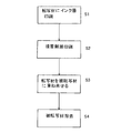
- the printing method can be printed using various printing methods such as ink jet printing, screen printing, and lithographic printing (FIG. 1; step S1).
- the metallic ink layer 2 is printed on the transfer material 1 using a solvent ink and dried using a heater or the like, the solvent is volatilized and aluminum particles are deposited on the transfer surface side to be about 0.1 ⁇ m to 0.2 ⁇ m.
- a metal layer having a thickness of 5 mm is formed.
- a release layer may be formed on the transfer surface of the transfer material 1 by coating, coating, or the like.
- the intermediate barrier layer 3 leveled on the metallic ink layer 2 printed on the transfer material 1 is laminated.
- the intermediate barrier layer 3 includes a first UV ink layer 3a laminated on the metallic ink layer 2, and a leveling layer (second UV ink layer) 3b laminated on the first UV ink layer 3a.
- the first UV ink layer 3a is a UV ink layer that ejects ink from the ink-jet head during scanning of a carriage on which the ink-jet head and the UV lamp are mounted, and is cured by the UV lamp immediately after ejection.
- the second UV ink layer 3b is a UV ink layer that has been leveled so that the surface opposite to the first UV ink layer 3a is a smooth surface.
- the inventor initially formed only the first UV ink layer 3 a as the intermediate barrier layer 3, but the intended glossiness was not obtained in the transferred metallic ink layer 2. Therefore, as a result of earnest research to investigate this cause, the flatness of the metallic ink layer 2 transferred by the uneven surface formed on the first UV ink layer 3a laminated on the metallic ink layer 2 is lost, causing irregular reflection. I found out.
- printing of the first UV ink layer 3a having a concavo-convex surface is performed by irradiating and curing the UV light from the UV lamp immediately after discharge while discharging the first UV ink to the metallic ink layer 2 using an inkjet printing apparatus.
- the second UV ink is ejected from the inkjet head onto the first UV ink layer 3a, but the UV light is not immediately irradiated, but the concave portion of the first UV ink layer 3a is filled with the second UV ink, and then UV light is irradiated with an interval. And leveling treatment for curing.
- the second UV ink layer 3b is filled in the concave portion of the first UV ink layer 3a by performing multiple scans of the ink jet head and performing an ink discharge operation a plurality of times.
- the UV adhesive layer 4 is printed by discharging UV ink from the inkjet head onto the leveled second UV ink layer 3b (FIG. 1; step S2).
- the UV adhesive layer 4 is also formed without discharging UV ink from the inkjet head and curing it. Since the ink component (monomer (reactive diluent, photopolymerizable monomer), etc.) of the UV adhesive layer 4 is prevented from penetrating the metallic ink layer 2 by the leveled intermediate barrier layer 3, A high-quality transfer printing layer can be formed without damaging the glossy metallic ink layer 2 such as cracks.
- the transfer material 1 is inverted and superimposed on the transfer material 5 (acrylic resin material, polycarbonate resin material, etc.) via the UV adhesive layer 4 (FIG. 1; step S3).
- the transfer material 1 (polyolefin film) follows the surface property of the printing surface (adhesion surface) even if the adhesion surface of the transfer material 5 is not a flat surface but a three-dimensional curved surface that is convex upward, for example. Can be overlapped.
- the material to be transferred 5 is made of a light transmissive material (acrylic resin material, polycarbonate resin material, etc.) having light transmittance. Therefore, the UV adhesive layer 4 is UV-cured and adhered by irradiating UV light from the side opposite to the adhesive surface of the transfer material 5 (in the direction of the arrow in FIG. 2D).
- the metallic ink layer 2 is peeled off from the transfer surface of the transfer material 1 that has been subjected to the release treatment, and the metallic ink layer 2 is made of a metal made of aluminum particles.
- the layer is transferred to the transfer material 5 as the outermost layer (FIG. 1; step S4).
- the printed matter 6 (see FIG. 2D) printed by the printing method described above can provide a glossy printed matter on which a high-quality image without cracks is printed. Further, since the transferred metallic ink layer 2 is formed with a metal layer in which aluminum particles are uniformly deposited on the outermost layer, metallic printing with high brightness and glossiness can be achieved without fading the metallic color.
- the solvent ink containing a solvent is used as an example of the metallic ink, but a UV curable ink may be used.
- middle barrier layer, and an adhesive bond layer with an inkjet printing apparatus can be performed by printing using UV ink, and a printing process can be simplified and performed efficiently.
- a UV color ink layer may be printed on the surface of the metal ink layer 2, and in this case, by adding various color colors to the metal color with high brightness and glossiness in the printed matter.
- the decorativeness can be enhanced.
- the transfer material 1 is formed of a light-transmitting material, the transfer material 1 can be directly bonded as a coating material and used as a printing medium.
Landscapes
- Ink Jet Recording Methods And Recording Media Thereof (AREA)
- Printing Methods (AREA)
- Decoration By Transfer Pictures (AREA)
Abstract
接着剤層にUVインクを用いても転写印刷層のひび割れを防止し高品位画像を印刷可能な印刷物の印刷方法を提供する。 転写材1に印刷された転写印刷層2にレべリングされた中間バリア層3を積層し、この中間バリア層3にUV硬化性を有するUV接着剤層4を積層するので、UV接着剤層4のインク成分がレべリングされた中間バリア層3によって転写印刷層2に浸透するのを阻止する。
Description
本発明は、印刷物の印刷方法及びこれを用いて印刷された印刷物に関する。
例えば、表面に金属のような質感を与える金属調印刷物としては、例えば基材層の上に転写されたメタリックインクの印刷層と、印刷層の上に積層される一方の面にヘアラインが形成された表皮層を熱プレスラミネートされた金属調樹脂フィルムが提案されている。
また、この金属調樹脂フィルムの製造方法としては、例えばPETフィルムなどの印刷補助フィルムの上にアクリル系の剥離層を積層し、クラビア印刷によりメタリックインクで印刷層を積層し、印刷層の上に酢酸ビニル系の接着層を積層して転写フィルムを形成する。次いで、熱可塑性フィルムからなる基材層の上に接着層を下にして転写フィルムを重ね合せて熱転写される。そして、最上層の印刷補助フィルムを除去して印刷フィルムを形成する。最後に印刷フィルムの印刷層の上に一方の面にサンドペーパー等でヘアラインが形成された表皮層を積層して熱プレスラミネートする。これにより、メタリックインクが割れることなく表皮層が剥離しにくい金属調樹脂フィルムが製造できることが開示されている(特許文献1参照)。
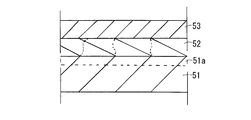
しかしながら、上述した印刷工程において、図3に示すように、転写面に剥離層51aを有する転写材51にメタリックインクを用いて印刷された転写印刷層52に、接着剤層53としてUVインクを積層した場合、転写印刷層にひび割れが発生するという問題があった。そこで、本願発明者は鋭意研究の結果、UVインクの塗布から当該UVインクを硬化させるまでの間に時間を要するため、UVインクの成分(モノマー(反応性希釈剤、光重合性単量体)等)が転写印刷層まで浸透してひび割れを起こすことを突き止め、転写印刷層と接着剤層との間に中間バリア層、より好ましくはレべリングされた中間バリア層を形成することを見出して本発明を提案するに至った。
即ち、本願発明の目的は、接着剤層にUVインクを用いても転写印刷層のひび割れを防止し高品位画像を印刷可能な印刷物の印刷方法及びこれを用いてひび割れのない高品位画像が印刷された印刷物を提供することを目的とする。
上記課題を解決するために、本発明に係る印刷物の印刷方法は、インクを転写材に印刷して転写印刷層を形成する印刷工程と、前記転写材に印刷された前記転写印刷層にレべリングされた中間バリア層を積層する工程と、前記中間バリア層にUV硬化性を有するUV接着剤層を積層する工程と、前記転写材を被転写材に前記UV接着剤層を介して重ね合わせて転写印刷層を接着する工程と、を含むことを特徴とする。
また、本発明において、前記印刷工程は、光沢性を有するインクを平滑な転写面を有する前記転写材に印刷することで前記転写印刷層を形成するのが好ましい。
これにより、光沢性を有する転写印刷層のひび割れを防いで高品位画像を印刷することができる。
これにより、光沢性を有する転写印刷層のひび割れを防いで高品位画像を印刷することができる。
また、本発明において、前記中間バリア層は、前記転写印刷層に積層したUVインク層と当該UVインク層に積層したレべリング層とを有し、前記UVインク層は、インクジェットヘッドとUVランプとが搭載されたキャリッジの走査において当該インクジェットヘッドからインクを吐出するとともに吐出直後に前記UVランプにより硬化させたUVインク層であり、前記レべリング層は、前記UVインク層とは反対面側が平滑面となるように印刷からUV硬化までインターバルを設けることによるレべリング処理が行われたレべリング層であることが望ましい。
例えば、転写印刷層に対してインクジェット印刷装置を用いて、第1UVインクを吐出しながら吐出直後からUVランプによりUV光を照射して硬化させることにより凹凸面を有する第1UVインク層の印刷を行う。故に、第1UVインクの塗布から第1UVインクを硬化させるまでの間に時間を要しないので、第1UVインクの成分が転写印刷層まで浸透しない。この第1UVインク層にインクジェットヘッドから第2UVインクを吐出するがすぐにUV光照射せずに第1UVインク層の凹部に第2UVインクを充填させてからインターバルを設けてUV光を照射して硬化させるレべリング処理を行う。この結果、第2UVインク層の第1UVインク層と反対面側に平滑面を形成することができる。これにより、転写印刷層を被転写材に転写しても第1UVインク層の凹凸により乱反射して光沢感を失うことなく印刷することができる。第2UVインク層の場合、第2UVインクの塗布から第2UVインクを硬化させるまでの間に時間を要するが、第2UVインクの成分は硬化した第1UVインク層により転写印刷層まで浸透しない。
例えば、転写印刷層に対してインクジェット印刷装置を用いて、第1UVインクを吐出しながら吐出直後からUVランプによりUV光を照射して硬化させることにより凹凸面を有する第1UVインク層の印刷を行う。故に、第1UVインクの塗布から第1UVインクを硬化させるまでの間に時間を要しないので、第1UVインクの成分が転写印刷層まで浸透しない。この第1UVインク層にインクジェットヘッドから第2UVインクを吐出するがすぐにUV光照射せずに第1UVインク層の凹部に第2UVインクを充填させてからインターバルを設けてUV光を照射して硬化させるレべリング処理を行う。この結果、第2UVインク層の第1UVインク層と反対面側に平滑面を形成することができる。これにより、転写印刷層を被転写材に転写しても第1UVインク層の凹凸により乱反射して光沢感を失うことなく印刷することができる。第2UVインク層の場合、第2UVインクの塗布から第2UVインクを硬化させるまでの間に時間を要するが、第2UVインクの成分は硬化した第1UVインク層により転写印刷層まで浸透しない。
また、本発明において、前記被転写材は光透過性を有する光透過材であり、前記被転写材にUV接着剤層を通じて前記転写材を重ね合わせて、当該被転写材の印刷面と反対面側よりUV光を照射して前記UV接着剤層を硬化させて前記転写印刷層が前記被転写材に接着するのが好ましい。これにより、被転写材の接着面は平坦面に限らず立体的な曲面でもよく、接着面の制約を受けずに転写印刷層を任意の箇所に重ね合わせた状態でUV硬化させて接着することができる。
更に、本発明において、前記転写印刷層は、溶剤に金属粒子を分散させたソルベントタイプのメタリックインクを平滑な転写面を有する前記転写材に金属粒子を転写面側に堆積させて印刷されるメタリックインク層であっても良い。これにより、溶剤中を金属粒子が容易に移動して、平滑な転写面に倣って堆積し易くなる、従って、被転写材に転写されたメタリックインク層は、最表層に一様に堆積した金属層が形成されているので、金属色がくすむことなく高輝度で高品位な光沢感のあるメタリック印刷が可能となる。
更にまた、本発明において、前記印刷工程はインクジェット印刷装置により前記転写材に少なくとも中間バリア層及びUV接着剤層が積層して印刷されても良い。これにより、転写材に印刷する転写印刷層の印刷工程を効率よく行うことができる。また、転写印刷層をUVインクにより印刷する場合には、印刷工程を簡略化しかつ効率よく行うことができる。
また、上述したいずれかの印刷方法を用いた印刷物にあっては、被転写材に接着剤層を介して中間バリア層、転写印刷層が積層されて接着されていることを特徴とする。
本発明によれば、転写材に印刷された転写印刷層にレべリングされた中間バリア層を積層し、この中間バリア層にUV硬化性を有するUV接着剤層を積層するので、UV接着剤層のインク成分がレべリングされた中間バリア層によって転写印刷層に浸透するのを阻止し転写印刷層にひび割れなどのダメージを与えることなく、高品位な転写画像を印刷することができる。
上述した印刷方法を用いて印刷された印刷物においては、ひび割れのない高品位画像が印刷された印刷物を提供することができる。
以下、図面を参照しながら、本発明に係る印刷物及びその印刷方法について説明する。
本実施形態で用いる光沢性のあるインクとしては、一例としてインクジェット印刷用のインクとして溶剤を含むソルベントタイプのソルベントインクが用いられる。インク成分としては、例えば主溶剤としてPnb(ポリプロピレングリコールノルマルブルエーテル);80~95重量%、他溶剤としてIPA(イソプロピルアルコール)、酢酸エチルや酢酸プロピル等;1重量%未満~20重量%、金属粒子として顔料;アルミペースト(若しくはアルミ合金)1重量%未満~5重量%、バインダーとして合成樹脂(ニトロセルロースほか)1重量%未満を含むものが用いられる。
本実施形態で用いる光沢性のあるインクとしては、一例としてインクジェット印刷用のインクとして溶剤を含むソルベントタイプのソルベントインクが用いられる。インク成分としては、例えば主溶剤としてPnb(ポリプロピレングリコールノルマルブルエーテル);80~95重量%、他溶剤としてIPA(イソプロピルアルコール)、酢酸エチルや酢酸プロピル等;1重量%未満~20重量%、金属粒子として顔料;アルミペースト(若しくはアルミ合金)1重量%未満~5重量%、バインダーとして合成樹脂(ニトロセルロースほか)1重量%未満を含むものが用いられる。
また、光沢性のあるアルミペースト(若しくはアルミ合金)に含まれる金属粒子の形態は、立体的な粒体状であっても、扁平な鱗片状(リーフ状)であってもいずれの形態でもよい。本実施形態では扁平な鱗片状(リーフ状)をしている。尚、ソルベントインクに代えて後述するようにUV硬化性インクを用いることも可能である。
また、金属粒子としては、銀色を表示するアルミペースト(若しくはアルミ合金)に限らず、金色を表示するブロンズ粉(銅粉及び亜鉛粉の混合物)やアルミペースト(若しくはアルミ合金)と黄色インクを混合した着色金インキなどであっても良い。
或いは光沢性のあるインクには、蛍光インクやシルキーインクなど他のインクを用いることも可能である。
或いは光沢性のあるインクには、蛍光インクやシルキーインクなど他のインクを用いることも可能である。
転写材としては、例えば、溶剤を受容できる受容層を有する無延伸のシート材(PET系フィルム、アクリルフィルム、オレフィン系フィルムなど)或いはブロック材などが用いられる。無延伸の転写材を用いたのは、転写材が延伸するとすれば、平坦面以外の被転写材に転写されると印刷面の歪みや変形が大きくなり、印刷品質が低下するからである。転写材の転写面は平滑面に形成され、また予め離型層(例えばフッ素系樹脂、シリコーン系樹脂、ワックスなどがコーティングされたもの)が形成されていることが望ましい。実験では、転写面がぬれ性を有する平滑面でかつ離型性を有する無延伸のポリオレフィン系フィルムを用いた。
UV接着剤は、中間バリア層と同様にバインダーとしてUVインクが用いられる。UV接着剤層は、後述するように中間バリア層と共にインクジェット印刷装置により印刷により形成される。
また、転写材に形成される転写印刷層が転写される被転写材は、UV接着剤を用いるため、被転写材は光透過性を有する光透過材を用いる必要がある。後述するように転写印刷層を被転写材に接着剤層を通じて転写する際に、当該被転写材の接着面と反対面側よりUV光を照射して接着剤層を硬化させる必要があるためである。本実施例では、被転写材では透明樹脂成形材(アクリル樹脂材、ポリカーボネート樹脂材など)が用いられる。尚、被転写材の転写印刷層の接着面は平坦面に限らず曲面であっても良い。
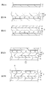
次に、印刷物の印刷方法の一例について、図1のフローチャートに基づいて、図2A~図2Eの模式断面図を参照しながら説明する。
先ず、図2Aにおいて、溶剤に外形が5μm程度の鱗片状のアルミ粒子(金属粒子)を分散させたソルベントインク(メタリックインク)を用いて、平滑な転写面を有するポリオレフィンフィルム(以下「転写材」という)1にメタリックインク層2(転写印刷層)を印刷する。ソルベントインクを用いることにより溶剤中をアルミ粒子が容易に移動するので、転写材1の平滑な転写面に倣ってアルミ粒子が堆積し易くなる。印刷方式は、インクジェット印刷、スクリーン印刷、平版印刷など様々な印刷方法を用いて印刷することが可能である(図1;ステップS1)。このとき、転写材1にソルベントインクを用いてメタリックインク層2を印刷しヒータ等を用いて乾燥すると、溶剤が揮発してアルミ粒子が転写面側に堆積して0.1μm~0.2μm程度の厚さの金属層を形成する。尚、転写材1の転写面には剥離層が塗布、コーティングなどにより形成されていても良い。
先ず、図2Aにおいて、溶剤に外形が5μm程度の鱗片状のアルミ粒子(金属粒子)を分散させたソルベントインク(メタリックインク)を用いて、平滑な転写面を有するポリオレフィンフィルム(以下「転写材」という)1にメタリックインク層2(転写印刷層)を印刷する。ソルベントインクを用いることにより溶剤中をアルミ粒子が容易に移動するので、転写材1の平滑な転写面に倣ってアルミ粒子が堆積し易くなる。印刷方式は、インクジェット印刷、スクリーン印刷、平版印刷など様々な印刷方法を用いて印刷することが可能である(図1;ステップS1)。このとき、転写材1にソルベントインクを用いてメタリックインク層2を印刷しヒータ等を用いて乾燥すると、溶剤が揮発してアルミ粒子が転写面側に堆積して0.1μm~0.2μm程度の厚さの金属層を形成する。尚、転写材1の転写面には剥離層が塗布、コーティングなどにより形成されていても良い。
次に、図2Bに示すように、転写材1に印刷されたメタリックインク層2にレべリングされた中間バリア層3を積層する。具体的には、中間バリア層3は、メタリックインク層2に積層した第1UVインク層3aと当該第1UVインク層3aに積層したレべリング層(第2UVインク層)3bとを有する。第1UVインク層3aは、インクジェットヘッドとUVランプとが搭載されたキャリッジの走査において当該インクジェットヘッドからインクを吐出するとともに吐出直後にUVランプにより硬化させたUVインク層である。一方、第2UVインク層3bは、第1UVインク層3aとは反対面側が平滑面となるようにレべリング処理が行われたUVインク層である。本願発明者は、当初中間バリア層3として第1UVインク層3aのみを形成したが、転写されたメタリックインク層2に所期の光沢が得られなかった。そこで、この原因を追究すべく鋭意研究の結果、メタリックインク層2に積層する第1UVインク層3aに形成された凹凸面により転写されたメタリックインク層2の平坦度が失われて乱反射を起こすことを突き止めた。
そこで、インクジェット印刷装置を用いて、メタリックインク層2に対して第1UVインクを吐出しながら吐出直後からUVランプによりUV光を照射して硬化させることにより凹凸面を有する第1UVインク層3aの印刷を行う。この第1UVインク層3aにインクジェットヘッドから第2UVインクを吐出するがすぐにUV光を照射せずに第1UVインク層3aの凹部に第2UVインクを充填させてからインターバルを設けてUV光を照射して硬化させるレべリング処理を行う。この結果、第2UVインク層3bの第1UVインク層3aと反対面側に平滑面を形成することができる(図2B参照)。これにより、メタリックインク層2を被転写材4に転写しても第1UVインク層3aの凹凸により乱反射して光沢感を失うことなく印刷することができる。尚、第2UVインク層3bは、インクジェットヘッドをマルチスキャンさせて複数回のインク吐出動作により第1UVインク層3aの凹部に第2UVインクを充填させている。
次に、図2Cに示すように、レべリング処理された第2UVインク層3bにインクジェットヘッドよりUVインクを吐出してUV接着剤層4を印刷する(図1;ステップS2)。UV接着剤層4も、インクジェットヘッドよりUVインクを吐出してUV硬化させることなく形成される。このUV接着剤層4のインク成分(モノマー(反応性希釈剤、光重合性単量体)等)がレべリングされた中間バリア層3によってメタリックインク層2に浸透するのを阻止するので、光沢性のあるメタリックインク層2にひび割れなどのダメージを与えることなく、高品位な転写印刷層を形成することができる。
次いで、図2Dに示すように転写材1を反転させて被転写材5(アクリル樹脂材、ポリカーボネート樹脂材など)にUV接着剤層4を介して重ね合わせる(図1;ステップS3)。このとき、被転写材5の接着面は平坦面でなく例えば上に凸となるような立体状の曲面であっても転写材1(ポリオレフィンフィルム)が印刷面(接着面)の面性状に倣って重ね合わせることができる。被転写材5は光透過性を有する光透過材(アクリル樹脂材、ポリカーボネート樹脂材等)が用いられている。よって、被転写材5の接着面と反対面側(図2Dの矢印方向)よりUV光を照射してUV接着剤層4をUV硬化させて接着させる。
最後に、図2Eに示すように、転写材1を剥がすことにより、メタリックインク層2が離型処理された転写材1の転写面より剥離して、当該メタリックインク層2がアルミ粒子よりなる金属層を最表層として被転写材5に転写される(図1;ステップS4)。
上述した印刷方法により印刷された印刷物6(図2D参照)は、ひび割れのない高品位画像が印刷された光沢性のある印刷物を提供することができる。
また、転写されたメタリックインク層2が最表層にアルミ粒子が一様に堆積した金属層が形成されているので、金属色がくすむことなく高輝度で光沢感のあるメタリック印刷が可能となる。
また、転写されたメタリックインク層2が最表層にアルミ粒子が一様に堆積した金属層が形成されているので、金属色がくすむことなく高輝度で光沢感のあるメタリック印刷が可能となる。
上述した実施形態では、メタリックインクの一例として溶剤を含有するソルベントインクを用いたが、UV硬化性のインクを用いても良い。
これにより、インクジェット印刷装置により転写印刷層、中間バリア層、接着剤層の形成がUVインクを用いた印刷により行うことができ、印刷工程を簡略化しかつ効率よく行うことができる。
これにより、インクジェット印刷装置により転写印刷層、中間バリア層、接着剤層の形成がUVインクを用いた印刷により行うことができ、印刷工程を簡略化しかつ効率よく行うことができる。
尚、印刷工程において、メタルインク層2の表面にUVカラーインク層を重ねて印刷しても良く、この場合には印刷物に高輝度で光沢感のあるメタル色に多彩なカラー色を加えることで装飾性を高めることができる。或いは、メタルインク層2にUVクリアインク層(透明インク層)を積層することで、印刷物に光沢感のほかに質感(立体感・奥行き)を加えることも可能である。
また、転写材1を光透過性のある材料で形成しておけば、転写材1をコート材としてそのまま接着して印刷媒体として用いることも可能である。
また、転写材1を光透過性のある材料で形成しておけば、転写材1をコート材としてそのまま接着して印刷媒体として用いることも可能である。
Claims (7)
- インクを転写材に印刷して転写印刷層を形成する印刷工程と、
前記転写材に印刷された前記転写印刷層にレべリングされた中間バリア層を積層する工程と、
前記中間バリア層にUV硬化性を有するUV接着剤層を積層する工程と、
前記転写材を被転写材に前記UV接着剤層を介して重ね合わせて転写印刷層を接着する工程と、を含むことを特徴とする印刷物の印刷方法。 - 前記印刷工程は、光沢性を有するインクを平滑な転写面を有する前記転写材に印刷することで前記転写印刷層を形成する請求項1記載の印刷物の印刷方法。
- 前記中間バリア層は、前記転写印刷層に積層したUVインク層と当該UVインク層に積層したレべリング層とを有し、前記UVインク層は、インクジェットヘッドとUVランプとが搭載されたキャリッジの走査において当該インクジェットヘッドからインクを吐出するとともに吐出直後に前記UVランプにより硬化させたUVインク層であり、前記レべリング層は、前記UVインク層とは反対面側が平滑面となるように印刷からUV硬化までインターバルを設けることによるレべリング処理が行われたレべリング層である請求項1又は請求項2記載の印刷物の印刷方法。
- 前記被転写材は光透過性を有する光透過材であり、前記被転写材にUV接着剤層を通じて前記転写材を重ね合わせて、当該被転写材の印刷面と反対面側よりUV光を照射して前記UV接着剤層を硬化させて前記転写印刷層が前記被転写材に接着する請求項1記載の印刷物の印刷方法。
- 前記転写印刷層は、溶剤に金属粒子を分散させたソルベントタイプのメタリックインクを平滑な転写面を有する前記転写材に金属粒子を転写面側に堆積させて印刷されるメタリックインク層である請求項1記載の印刷物の印刷方法。
- 前記印刷工程はインクジェット印刷装置により前記転写材に少なくとも中間バリア層及びUV接着剤層が積層して印刷される請求項1記載の印刷物の印刷方法。
- 請求項1乃至請求項6に記載のいずれかの印刷物の印刷方法を用いて、被転写材に接着剤層を介して中間バリア層、転写印刷層が積層されて接着されていることを特徴とする印刷物。
Applications Claiming Priority (2)
| Application Number | Priority Date | Filing Date | Title |
|---|---|---|---|
| JP2011029948A JP5664911B2 (ja) | 2011-02-15 | 2011-02-15 | 印刷物の印刷方法及び印刷物 |
| JP2011-029948 | 2011-02-15 |
Publications (1)
| Publication Number | Publication Date |
|---|---|
| WO2012111243A1 true WO2012111243A1 (ja) | 2012-08-23 |
Family
ID=46672192
Family Applications (1)
| Application Number | Title | Priority Date | Filing Date |
|---|---|---|---|
| PCT/JP2011/080494 Ceased WO2012111243A1 (ja) | 2011-02-15 | 2011-12-28 | 印刷物の印刷方法及び印刷物 |
Country Status (2)
| Country | Link |
|---|---|
| JP (1) | JP5664911B2 (ja) |
| WO (1) | WO2012111243A1 (ja) |
Cited By (2)
| Publication number | Priority date | Publication date | Assignee | Title |
|---|---|---|---|---|
| JP2015074122A (ja) * | 2013-10-07 | 2015-04-20 | 株式会社ミマキエンジニアリング | 積層体の製造方法 |
| JP2018118452A (ja) * | 2017-01-26 | 2018-08-02 | 洋治 杉山 | 転写加工方法及び転写加工製品 |
Families Citing this family (6)
| Publication number | Priority date | Publication date | Assignee | Title |
|---|---|---|---|---|
| JP2014233922A (ja) * | 2013-06-03 | 2014-12-15 | 株式会社ミマキエンジニアリング | 積層体の製造方法 |
| JP6190628B2 (ja) * | 2013-06-05 | 2017-08-30 | 株式会社ミマキエンジニアリング | 被転写体製造方法、インクジェットプリンタ、転写フィルム及び被転写体 |
| JP6888369B2 (ja) * | 2017-03-30 | 2021-06-16 | 大日本印刷株式会社 | 転写シート |
| US20190240897A1 (en) * | 2018-02-07 | 2019-08-08 | Xerox Corporation | Transfer of uv print onto curved surfaces with stretchable uv inks |
| US10286689B1 (en) * | 2018-02-08 | 2019-05-14 | Xerox Corporation | UV printed transferrable materials |
| KR102390568B1 (ko) * | 2022-01-04 | 2022-04-27 | 승화프린팅(주) | 라벨용 포장필름 ,그의 제조방법 및 그를 부착한 포장필름 |
Citations (4)
| Publication number | Priority date | Publication date | Assignee | Title |
|---|---|---|---|---|
| JPS6418698A (en) * | 1987-07-15 | 1989-01-23 | Dainippon Printing Co Ltd | Transfer sheet with ionizing radiation curing protective layer |
| JP2004142107A (ja) * | 2002-10-21 | 2004-05-20 | Nissha Printing Co Ltd | 加飾シートおよび加飾品 |
| JP2006124826A (ja) * | 2004-09-29 | 2006-05-18 | Mitsubishi Materials Corp | 金属コロイド粒子及び金属コロイド並びに該金属コロイドの用途 |
| JP2007160648A (ja) * | 2005-12-13 | 2007-06-28 | Shin Etsu Polymer Co Ltd | 金属調加飾シートおよびその製造方法 |
Family Cites Families (1)
| Publication number | Priority date | Publication date | Assignee | Title |
|---|---|---|---|---|
| JP4667001B2 (ja) * | 2004-10-29 | 2011-04-06 | 小島プレス工業株式会社 | 金属調樹脂フィルムの製造方法 |
-
2011
- 2011-02-15 JP JP2011029948A patent/JP5664911B2/ja not_active Expired - Fee Related
- 2011-12-28 WO PCT/JP2011/080494 patent/WO2012111243A1/ja not_active Ceased
Patent Citations (4)
| Publication number | Priority date | Publication date | Assignee | Title |
|---|---|---|---|---|
| JPS6418698A (en) * | 1987-07-15 | 1989-01-23 | Dainippon Printing Co Ltd | Transfer sheet with ionizing radiation curing protective layer |
| JP2004142107A (ja) * | 2002-10-21 | 2004-05-20 | Nissha Printing Co Ltd | 加飾シートおよび加飾品 |
| JP2006124826A (ja) * | 2004-09-29 | 2006-05-18 | Mitsubishi Materials Corp | 金属コロイド粒子及び金属コロイド並びに該金属コロイドの用途 |
| JP2007160648A (ja) * | 2005-12-13 | 2007-06-28 | Shin Etsu Polymer Co Ltd | 金属調加飾シートおよびその製造方法 |
Cited By (2)
| Publication number | Priority date | Publication date | Assignee | Title |
|---|---|---|---|---|
| JP2015074122A (ja) * | 2013-10-07 | 2015-04-20 | 株式会社ミマキエンジニアリング | 積層体の製造方法 |
| JP2018118452A (ja) * | 2017-01-26 | 2018-08-02 | 洋治 杉山 | 転写加工方法及び転写加工製品 |
Also Published As
| Publication number | Publication date |
|---|---|
| JP2012166472A (ja) | 2012-09-06 |
| JP5664911B2 (ja) | 2015-02-04 |
Similar Documents
| Publication | Publication Date | Title |
|---|---|---|
| JP5664911B2 (ja) | 印刷物の印刷方法及び印刷物 | |
| CN103370208B (zh) | 金属感印刷物的印刷方法以及金属感印刷物 | |
| CN1551838A (zh) | 数字印刷产品及工艺 | |
| JP7361074B2 (ja) | メディアの製造方法 | |
| JP2014124941A (ja) | 薄膜転写物の製造方法、液体吐出装置、及び液体吐出方法 | |
| CN103796767A (zh) | 紫外线墨水固定构造及紫外线墨水印刷方法 | |
| JP5793908B2 (ja) | 加飾フィルム及び加飾成形品 | |
| TW201139163A (en) | Transfer sheet having part light extinction and hard coating to prevent attachment of printing slurry | |
| JP5651797B1 (ja) | ハードコート転写フィルムの製造方法及びハードコート転写フィルム並びにハードコート層を備えた高分子樹脂板又は高分子樹脂フィルム。 | |
| JP7074436B2 (ja) | 装飾シート、装飾シートを含む構造体及び装飾シートの製造方法 | |
| JP2015507544A (ja) | 加飾熱可塑性フィルムおよびそれを作製するための方法 | |
| JP7712722B2 (ja) | 複合印刷による転写箔の製造方法及び転写箔 | |
| CN111572230A (zh) | 喷墨式图像转印贴纸及其制造方法 | |
| CN107443816A (zh) | 工艺玻璃及其制作方法 | |
| US20140162192A1 (en) | Photopolymer Imaging from Solvent Ink Film Images | |
| JP2016037006A (ja) | 印刷物の製造方法、印刷方法、及び印刷装置 | |
| CN114126893B (zh) | 记录介质、装饰片、装饰品、以及装饰品的制造方法 | |
| JP2013111942A (ja) | 熱転写箔およびその製造方法 | |
| JP2011231254A (ja) | エンボスインキ、部分マットハードコート転写シートと部分マットハードコート成形品の製造方法 | |
| WO2012105295A1 (ja) | 導光板を製造する方法 | |
| JP5656168B2 (ja) | 印刷方法、転写材、およびインクジェット吐出装置 | |
| JP2015025884A (ja) | 両面印刷ラベル及び両面印刷ラベルの作製方法 | |
| JP7327710B1 (ja) | 加飾シート、加飾成形品の製造方法、離型部材付き転写シート、離型部材付き加飾シート、転写シート前駆体、加飾シート前駆体、転写シートの製造方法、加飾シートの製造方法、および加飾物品の製造方法 | |
| JP5322606B2 (ja) | ホログラム調加飾シートの製造方法とこれに用いるホログラムリボンの製造方法、および成形同時加飾成形品の製造方法 | |
| JP2011011378A (ja) | 転写シート、転写シートの製造方法及び転写品 |
Legal Events
| Date | Code | Title | Description |
|---|---|---|---|
| 121 | Ep: the epo has been informed by wipo that ep was designated in this application |
Ref document number: 11858813 Country of ref document: EP Kind code of ref document: A1 |
|
| NENP | Non-entry into the national phase |
Ref country code: DE |
|
| 122 | Ep: pct application non-entry in european phase |
Ref document number: 11858813 Country of ref document: EP Kind code of ref document: A1 |