WO2012105641A1 - プラズマ処理装置 - Google Patents
プラズマ処理装置 Download PDFInfo
- Publication number
- WO2012105641A1 WO2012105641A1 PCT/JP2012/052361 JP2012052361W WO2012105641A1 WO 2012105641 A1 WO2012105641 A1 WO 2012105641A1 JP 2012052361 W JP2012052361 W JP 2012052361W WO 2012105641 A1 WO2012105641 A1 WO 2012105641A1
- Authority
- WO
- WIPO (PCT)
- Prior art keywords
- vacuum furnace
- plasma processing
- processing apparatus
- power feeding
- supply device
- Prior art date
- Legal status (The legal status is an assumption and is not a legal conclusion. Google has not performed a legal analysis and makes no representation as to the accuracy of the status listed.)
- Ceased
Links
Images




Classifications
-
- C—CHEMISTRY; METALLURGY
- C23—COATING METALLIC MATERIAL; COATING MATERIAL WITH METALLIC MATERIAL; CHEMICAL SURFACE TREATMENT; DIFFUSION TREATMENT OF METALLIC MATERIAL; COATING BY VACUUM EVAPORATION, BY SPUTTERING, BY ION IMPLANTATION OR BY CHEMICAL VAPOUR DEPOSITION, IN GENERAL; INHIBITING CORROSION OF METALLIC MATERIAL OR INCRUSTATION IN GENERAL
- C23C—COATING METALLIC MATERIAL; COATING MATERIAL WITH METALLIC MATERIAL; SURFACE TREATMENT OF METALLIC MATERIAL BY DIFFUSION INTO THE SURFACE, BY CHEMICAL CONVERSION OR SUBSTITUTION; COATING BY VACUUM EVAPORATION, BY SPUTTERING, BY ION IMPLANTATION OR BY CHEMICAL VAPOUR DEPOSITION, IN GENERAL
- C23C16/00—Chemical coating by decomposition of gaseous compounds, without leaving reaction products of surface material in the coating, i.e. chemical vapour deposition [CVD] processes
- C23C16/44—Chemical coating by decomposition of gaseous compounds, without leaving reaction products of surface material in the coating, i.e. chemical vapour deposition [CVD] processes characterised by the method of coating
- C23C16/448—Chemical coating by decomposition of gaseous compounds, without leaving reaction products of surface material in the coating, i.e. chemical vapour deposition [CVD] processes characterised by the method of coating characterised by the method used for generating reactive gas streams, e.g. by evaporation or sublimation of precursor materials
-
- C—CHEMISTRY; METALLURGY
- C21—METALLURGY OF IRON
- C21D—MODIFYING THE PHYSICAL STRUCTURE OF FERROUS METALS; GENERAL DEVICES FOR HEAT TREATMENT OF FERROUS OR NON-FERROUS METALS OR ALLOYS; MAKING METAL MALLEABLE, e.g. BY DECARBURISATION OR TEMPERING
- C21D1/00—General methods or devices for heat treatment, e.g. annealing, hardening, quenching or tempering
- C21D1/06—Surface hardening
- C21D1/09—Surface hardening by direct application of electrical or wave energy; by particle radiation
-
- C—CHEMISTRY; METALLURGY
- C21—METALLURGY OF IRON
- C21D—MODIFYING THE PHYSICAL STRUCTURE OF FERROUS METALS; GENERAL DEVICES FOR HEAT TREATMENT OF FERROUS OR NON-FERROUS METALS OR ALLOYS; MAKING METAL MALLEABLE, e.g. BY DECARBURISATION OR TEMPERING
- C21D1/00—General methods or devices for heat treatment, e.g. annealing, hardening, quenching or tempering
- C21D1/34—Methods of heating
- C21D1/38—Heating by cathodic discharges
-
- C—CHEMISTRY; METALLURGY
- C21—METALLURGY OF IRON
- C21D—MODIFYING THE PHYSICAL STRUCTURE OF FERROUS METALS; GENERAL DEVICES FOR HEAT TREATMENT OF FERROUS OR NON-FERROUS METALS OR ALLOYS; MAKING METAL MALLEABLE, e.g. BY DECARBURISATION OR TEMPERING
- C21D1/00—General methods or devices for heat treatment, e.g. annealing, hardening, quenching or tempering
- C21D1/74—Methods of treatment in inert gas, controlled atmosphere, vacuum or pulverulent material
- C21D1/773—Methods of treatment in inert gas, controlled atmosphere, vacuum or pulverulent material under reduced pressure or vacuum
-
- F—MECHANICAL ENGINEERING; LIGHTING; HEATING; WEAPONS; BLASTING
- F27—FURNACES; KILNS; OVENS; RETORTS
- F27B—FURNACES, KILNS, OVENS OR RETORTS IN GENERAL; OPEN SINTERING OR LIKE APPARATUS
- F27B5/00—Muffle furnaces; Retort furnaces; Other furnaces in which the charge is held completely isolated
- F27B5/04—Muffle furnaces; Retort furnaces; Other furnaces in which the charge is held completely isolated adapted for treating the charge in vacuum or special atmosphere
-
- F—MECHANICAL ENGINEERING; LIGHTING; HEATING; WEAPONS; BLASTING
- F27—FURNACES; KILNS; OVENS; RETORTS
- F27B—FURNACES, KILNS, OVENS OR RETORTS IN GENERAL; OPEN SINTERING OR LIKE APPARATUS
- F27B5/00—Muffle furnaces; Retort furnaces; Other furnaces in which the charge is held completely isolated
- F27B5/06—Details, accessories or equipment specially adapted for furnaces of these types
-
- F—MECHANICAL ENGINEERING; LIGHTING; HEATING; WEAPONS; BLASTING
- F27—FURNACES; KILNS; OVENS; RETORTS
- F27D—DETAILS OR ACCESSORIES OF FURNACES, KILNS, OVENS OR RETORTS, IN SO FAR AS THEY ARE OF KINDS OCCURRING IN MORE THAN ONE KIND OF FURNACE
- F27D7/00—Forming, maintaining or circulating atmospheres in heating chambers
- F27D7/06—Forming or maintaining special atmospheres or vacuum within heating chambers
Definitions
- the present invention relates to a plasma processing apparatus.
- This application claims priority based on Japanese Patent Application No. 2011-20665 filed in Japan on February 2, 2011, the contents of which are incorporated herein by reference.
- This plasma processing apparatus includes a vacuum furnace as shown in, for example, Patent Document 1, generates plasma in a low-pressure environment inside the vacuum furnace, and uses the plasma to surface the object to be processed such as carburizing treatment. We are reforming.
- an object to be processed is usually placed on a conductive tray and placed inside a vacuum furnace. Then, the inner wall of the vacuum furnace is grounded and a negative voltage is applied to the tray. As a result, an electric field is formed between the inner wall and the object to be processed, the processing gas is turned into plasma, and the surface of the object to be processed is modified.
- the distance to the inner wall of a vacuum furnace changes with to-be-processed objects.
- a change in the distance from the object to be processed to the inner wall of the vacuum furnace means that the electric field formed between the object to be processed and the inner wall of the vacuum furnace changes.
- the environment of plasma processing will change, and the surface characteristics of the workpiece after processing will vary.
- the power supply point to the tray and the inner wall of the vacuum furnace cannot be changed. For this reason, as a result, the above-mentioned change in the electric field cannot be arbitrarily changed, and the variation in the surface characteristics of the object to be processed is suppressed, or the surface characteristics of the object to be processed are intentionally changed. It is difficult.
- the present invention has been made in view of the above-described problems.
- a plasma processing apparatus that performs surface modification of an object to be processed using plasma inside a vacuum furnace
- an electric field strength for generating plasma is arbitrarily set.
- the purpose is to improve the degree of freedom in surface modification of the workpiece.
- the present invention adopts the following configuration as means for solving the above-described problems.
- 1st invention is the plasma processing apparatus which performs surface modification by the plasma with respect to the to-be-processed object which consists of metal materials inside a vacuum furnace, Comprising: The 1st electric power feeder which applies a 1st voltage to the said to-be-processed object And a second power feeding device that applies a second voltage different from the first voltage to the metal body arranged to face the object to be processed, the first power feeding device and the second power feeding device. At least one of them adopts a configuration in which it is composed of a movable power feeding device that is movable inside the vacuum furnace.
- the movable power feeding device includes a conductive bar member inserted from the outside of the vacuum furnace into the vacuum furnace, and a conductive rope member connected to the bar member.
- the configuration is provided with.
- 3rd invention employs the structure that the said rope member is installed two or more in the said 2nd invention.
- the fourth invention employs a configuration in which the movable feeding device is arranged closer to the opening / closing door than the center of the vacuum furnace in any of the first to third inventions.
- the metal body to which the second voltage is applied by the second power feeding device is a detachable electrode that can be taken in and out of the vacuum furnace. Is adopted.
- the sixth aspect of the present invention employs a configuration in which, in any one of the first to fifth aspects of the present invention, a mounting portion for mounting the object to be processed is insulated inside the vacuum furnace.
- a heater installed in the vacuum furnace, a carburizing gas supply device for supplying a carburizing gas into the vacuum furnace, and the inside of the vacuum furnace.
- a configuration including a cooling device for cooling is employed.
- a first power supply device that applies a first voltage to the object to be processed
- a second power supply that applies a second voltage different from the first voltage to a metal body arranged to face the object to be processed.
- At least one of the devices is composed of a movable power feeding device that is movable inside the vacuum furnace. According to the present invention, it is possible to change a power feeding point to the inner wall of a tray or a vacuum furnace by using a movable power feeding device.
- a metal body having an arbitrary shape can be disposed opposite to the object to be processed to supply power to the metal body. For this reason, according to the present invention, it is possible to arbitrarily change the electric field strength for plasma generation, thereby improving the degree of freedom in the surface modification of the workpiece.
- FIG. 1 is a schematic configuration diagram of a plasma processing apparatus S1 of the present embodiment.
- the plasma processing apparatus S1 of this embodiment includes a vacuum furnace 1, a vacuum pump 2, a processing gas supply apparatus 3, a cooling gas supply apparatus 4, a power supply apparatus 5, and a control apparatus 6. It has.
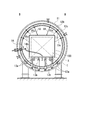
- FIG. 2 is a side sectional view of the vacuum furnace 1.
- 3A and 3B are front sectional views of the vacuum furnace 1, FIG. 3A is a sectional view taken along line AA in FIG. 2, and FIG. 3B is a sectional view taken along line BB in FIG.
- the vacuum furnace 1 includes a container 11, a side shield plate 12, a placement unit 13, a first power feeding unit 14 (first power feeding device), and a second power feeding unit 15 ( 2nd electric power feeder), the heater 16, and the cooling device 17 are provided.
- the container 11 has a substantially cylindrical shape in order to form the outer shape of the vacuum furnace 1, and accommodates the mounting portion 13 and the heater 16 therein.
- a water-cooled double walled one is preferably used as the container 11, for example.
- the container 11 includes an open / close door 11 a that can be opened and closed in the horizontal direction at one end in the horizontal direction. Then, the workpiece X can be taken in and out of the vacuum furnace 1 by opening the door 11a.
- the side shield plate 12 is disposed inside the container 11 so as to surround a region where the workpiece X is plasma-processed (a central region in the inner region of the container 11), and heat or the like is transmitted to the container 11.
- the heat insulating material 12c which suppresses this is pressed down.
- the side shield plate 12 is supported via a heat insulating material 12c by an internal panel 12b fixed to the container 11 by a fixture 12a.
- the side shield plate 12, the internal panel 12b, and the heat insulating material 12c have a ventilation region such as a through hole through which a gas such as a processing gas can pass.
- a carbon composite material having a thickness of about 1 mm or a molybdenum (Mo) plate having a thickness of about 0.3 mm can be used.
- the inter panel 12b for example, an SS material or a SUS material having a thickness of about 4.5 mm to 5 m can be used.
- the heat insulating material 12c for example, a ceramic blanket made of alumina (Al 2 O 3 ) can be used.
- the container 11 is grounded, and the voltage of the container 11 and the side shield plate 12 is set to the ground level.
- the placement unit 13 places the tray T on which the workpiece X is placed inside the vacuum furnace 1, and supports the placement beam 13a on which the tray T is directly placed, and the placement beam 13a. And a support bar 13b.
- the support bar 13b is made of, for example, graphite.
- the support bar 13b is insulated from the side shield plate 12 by the ceramics attached to the peripheral surface of the support bar 13b and the ceramics attached to the side shield plate 12 to such an extent that the support bar 13b is not overheated. Yes. Since the support bar 13b is insulated from the side shield plate 12, the entire mounting portion 13 is insulated.
- the 1st electric power feeding part 14 functions as a movable electric power feeding apparatus of this invention which applied the negative voltage (1st voltage) with respect to the to-be-processed object X, and was enabled to move inside the vacuum furnace 1.
- the 1st electric power feeding part 14 is provided with the electroconductive rod member 14a penetrated by the inside of the vacuum furnace 1 from the exterior of the vacuum furnace 1, and the electroconductive rope member 14b connected with the rod member 14a. ing.
- the 1st electric power feeding part 14 is comprised so that the rope member 14b can be connected to the arbitrary places of the tray T in which the to-be-processed object X or the to-be-processed object X was mounted.
- FIG. 4 is an enlarged view of a main part including the first power feeding unit 14.
- a ceramic tube 12 d is disposed through the inter panel 12 b, the heat insulating material 12 c, and the side plate shield plate 12.
- the bar member 14a of the first power feeding unit 14 is inserted through the ceramic tube 12d to the inside of the side shield plate 12.
- a plurality of (for example, three in the present embodiment) through-holes 14d are formed in the distal end portion 14c located in the internal space surrounded by the side shield plate 12.
- the rope member 14b is coupled to the rod member 14a by passing through a through hole 14d formed at the tip of the rod member 14a and being tied to the rod member 14a.
- the single rope member 14b is bound by passing through one through hole 14d. That is, in the plasma processing apparatus S1 of the present embodiment, three rope members 14b can be connected to the rod member 14a.
- the rope member 14b can be formed using, for example, a graphite yarn.
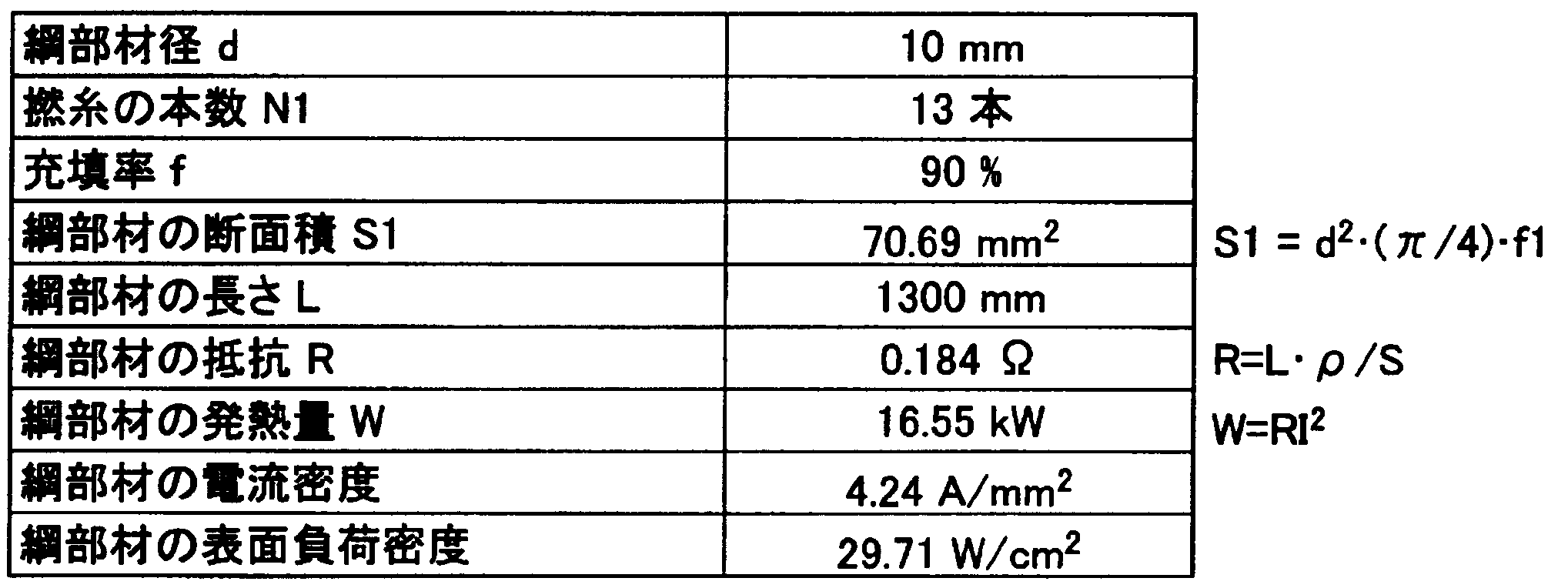
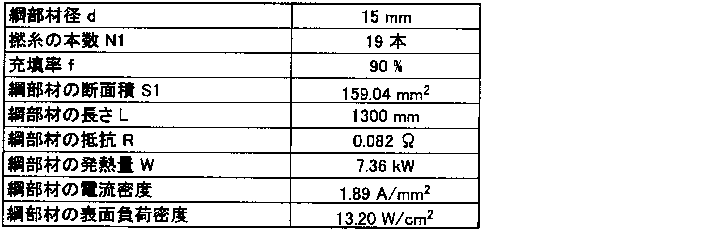
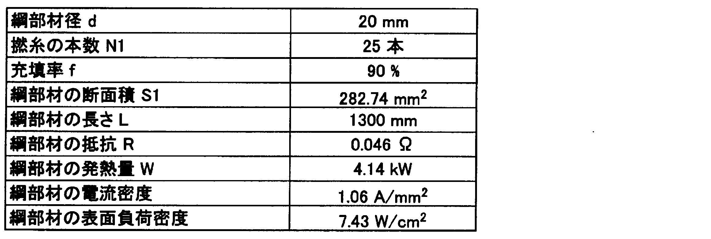
- the calorific value of the rope member 14b depends on the current density in the rope member 14b.
- the current density of the rope member 14b is preferably 1.2 A / mm 2 or less.
- Table 1 shows the physical properties of graphite yarn
- Table 2 shows various values when the steel diameter d is 10 mm
- Table 3 shows various values when the steel diameter d is 20 mm
- Table 4 shows the steel diameter d.
- Various values in the case of 30 mm are shown.
- the power supplied to the rope member 14b is assumed to have a voltage of 700V and a current of 300A.
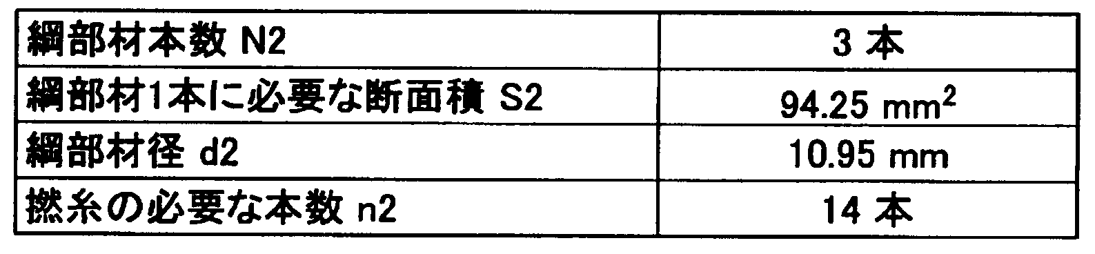
- the three rope members 14b can be connected in parallel to the bar member 14a. For this reason, it is preferable not to provide one rope member having a rope diameter d of 20 mm, but to provide a plurality of rope members 14b to reduce the weight per piece.
- the rope diameter d2 of the rope members 14b per one may be set as shown in Tables 5 and 6 below.
- the first power feeding unit 14 is disposed closer to the open / close door 11a than the center of the vacuum furnace 1. Specifically, when the workpiece X is accommodated in the vacuum furnace 1 and the open / close door 11a is opened, the first power feeding unit 14 is connected to the rope member 14b of the first power feeding unit 14 by the operator. It is placed within reach.
- the second power feeding unit 15 supports the side shield plate 12, feeds a ground level voltage (second voltage) to the side shield plate 12, and is movable inside the vacuum furnace 1. It functions as a movable power feeder.
- 5A and 5B are enlarged views including the second power supply unit 15, FIG. 5A is an enlarged view of a part of the vacuum furnace including the second power supply unit 15, and FIG. 5B is only the second power supply unit 15.
- FIG. 5A is an enlarged view of a part of the vacuum furnace including the second power supply unit
- FIG. 5B is only the second power supply unit 15.
- the second power feeding unit 15 includes a bar member 15a, a fixing member 15b, and a rope member 15c.
- the bar member 15a penetrates the inter panel 12b, the heat insulating material 12c, and the side plate shield plate 12, and is disposed in an internal space surrounded by the side plate shield plate 12 at the front end portion 15a1, and is a conductive member.
- the rod member 15a is made of, for example, a molybdenum (Mo) material or a carbon composite.
- a plurality of through holes 15a2 for inserting the rope members 15c are provided at the distal end portion 15a1 of the bar member 15a.
- the fixing member 15b fixes the bar member 15a.
- the fixing member 15b is inserted into one of a through hole 15a2 and a bolt 15b1 for fixing the bar member 15a to the inter panel 12b, a stop plate 15b2 through which the bar member 15a penetrates and abuts against the inner wall of the side plate shield plate 12.
- the stop plate 15b2 is formed of, for example, a carbon composite material, and the wire member 15b3 is formed of molybdenum (Mo) material.
- the rope member 15c is configured such that one end thereof is inserted and fixed in a through hole 15a2 provided in the distal end portion 15a1 of the rod member 15a, and the other end is connectable to a later-described electrode (attachment electrode 100). Yes.
- an arc electrode is used as the retrofitted electrode. Since the rope member 15c can be freely moved inside the vacuum furnace 1, it is possible to connect to the attachment electrode 100 regardless of the shape of the attachment electrode 100 by considering only the length.
- the number of the second power feeding units 15 is set so that the current density in each second power feeding unit 15 does not affect the plasma forming environment of the vacuum furnace 1.
- the number of second power feeding portions 15 is set so that the current density in the rope member 15c is 1.2 A / mm 2 or less.
- a hanging jig 18 is provided alongside the second power feeding unit 15.
- the hanging jig 18 is a jig for hanging the mounting electrode 100 inside the vacuum furnace 1.
- the hanging jig 18 is formed by extending a pin member 12 c that protrudes from the internal panel 12 b and supports the side shield plate 12 to the inside of the side shield plate 12. Note that the tip of the hanging jig 18 is formed into a shape having irregularities by being threaded so that the attachment electrode 100 can be easily hung and a nut is attached.
- the attachment electrode 100 (metal body) is comprised with respect to the inside of the vacuum furnace 1 so that attachment is possible.
- the attachment electrode 100 is supported by being suspended by the suspension jig 18, connected to the rope member 15 c, and applied with a ground level voltage from the second power feeding unit 15.
- the shape of the attachment electrode 100 shown in FIGS. 3A and 3B is an example, and can be arbitrarily changed so as to be applicable to the shape of the workpiece X or the like.
- the heater 16 heats the workpiece X placed inside the vacuum furnace 1.
- a plurality of heaters 16 (for example, six in the present embodiment) are arranged as viewed from the open / close door 11a side of the vacuum furnace 1.
- each heater 16 is annularly disposed so as to surround a region where the workpiece X is subjected to plasma processing (a central region in the inner region of the container 11).
- the cooling device 17 circulates and cools the cooling gas supplied into the container 11.
- the cooling device 17 includes a fan 17a that circulates cooling gas, a motor 17b that rotationally drives the fan 17a, a heat exchanger 17c that cools the cooling gas, and the like.
- the vacuum pump 2 is connected to the exhaust port 11 b (see FIGS. 3A and 3B) of the container 11 and discharges the gas in the container 11.
- the processing gas supply device 3 is connected to the container 11 and supplies a processing gas (carburizing gas) into the container 11.
- the cooling gas supply device 4 is connected to a header pipe or the like disposed in the container 11 and supplies cooling gas into the container 11.
- the power supply device 5 is electrically connected to the first power supply unit 14 and generates a negative voltage that is applied to the tray T via the first power supply unit 14.
- the control device 6 controls the overall operation of the plasma processing apparatus S1 of this embodiment.
- the control device 6 is electrically connected to the vacuum furnace 1, the vacuum pump 2, the processing gas supply device 3, the cooling gas supply device 4, and the power supply device 5.
- the tray T on which the workpiece X is placed is accommodated in the vacuum furnace 1. Specifically, the workpiece X is accommodated in the vacuum furnace 1 by placing the tray T on the placement unit 13.
- the attachment electrode 100 is attached. Specifically, the attachment electrode 100 is suspended from the hanging jig 18, and the rope member 15 c of the second power feeding unit 15 is connected to the attachment electrode 100. Note that the attachment electrode 100 suspended by the suspension jig 18 is disposed to face the workpiece X in a non-contact manner. Then, a ground level voltage is applied to the suspended attachment electrode 100 via the second power feeding unit 15.
- the rope member 14b of the first power feeding unit 14 is connected to the tray T.
- the rope member 14b of the 1st electric power feeding part 14 is made into the wire harness shape which has a connector, and the connector which can be joined with the connector of the rope member 14b is installed in the tray T. Thereby, the rope member 14b can be easily connected to the tray T.
- the workpiece X is accommodated in the vacuum furnace 1, the attachment electrode 100 is attached to the vacuum furnace 1, and the open / close door 11a of the container 11 is closed. Subsequently, the control device 6 performs heat treatment, plasma treatment, and cooling treatment on the workpiece X based on an instruction from an operation device (not shown).
- the control device 6 heats the workpiece X using the heater 16. Specifically, the control device 6 exhausts the air in the container 11 by the vacuum pump 2 and supplies the processing gas into the container 11 by the processing gas supply device 3. Then, the control device 6 heats the workpiece X by causing the heater 16 to generate heat.
- the control device 6 applies a negative voltage to the workpiece X via the first power supply unit 14 by the power supply device 5.
- the processing gas is converted into plasma by the electric field generated between the processing object X and the attachment electrode 100, and the surface of the processing object X is exposed to the plasma and subjected to plasma processing.
- control device 6 uses the cooling device 17 to cool the workpiece X when the workpiece X is cooled. Specifically, the control device 6 exhausts the processing gas in the container 11 with the vacuum pump 2 and supplies the cooling gas into the container 11 with the cooling gas supply device 4. And the control apparatus 6 cools the to-be-processed object X by circulating cooling gas with cooling device 17 cooling.
- the inside of the container 11 is opened to the atmosphere, the open / close door 11a is opened, and the workpiece X is taken out together with the tray T.
- the second power supply unit 15 that applies a ground-level voltage (second voltage) includes a movable power supply device that is movable in the vacuum furnace 1. According to the plasma processing apparatus S1 of the present embodiment, it is possible to easily change the power supply point to the tray T and the mounting electrode. For this reason, it is possible to arbitrarily change the electric field strength for plasma generation. As a result, it is possible to easily perform a treatment adapted to the shape change or the like of the workpiece X, and it is possible to improve the degree of freedom in surface modification of the workpiece X.
- the 1st electric power feeding part 14 is electrically conductive rod member 14a inserted in the vacuum furnace 1 inside from the vacuum furnace 1, and the electroconductivity connected with the rod member 14a.
- the rope member 14b is electrically conductive rod member 14a inserted in the vacuum furnace 1 inside from the vacuum furnace 1, and the electroconductivity connected with the rod member 14a.
- the rope member 14b is electrically conductive rod member 14a inserted in the vacuum furnace 1 inside from the vacuum furnace 1, and the electroconductivity connected with the rod member 14a.
- the rope member 14b for this reason, the 1st electric power feeding part 14 can be easily connected to the arbitrary locations of the tray T by moving the front-end
- the 1st electric power feeding part 14 is arrange
- the structure which is the attachment electrode 100 in which the metal body electrically fed by the 2nd electric power feeding part 15 is removable is employ
- the mounting part 13 which mounts the to-be-processed object X inside the vacuum furnace 1 is electrically insulated. For this reason, it can suppress that the mounting part 13 charges, and can suppress that dust etc. adhere to the mounting part 13.
- the plasma processing apparatus S1 of the present embodiment includes a heater 16 installed inside the vacuum furnace 1, a processing gas supply apparatus 3 (carburizing gas supply apparatus) that supplies a processing gas (carburizing gas) to the inside of the vacuum furnace 1, and And a cooling device 17 (cooling device) for cooling the inside of the vacuum furnace 1.
- a processing gas supply apparatus 3 carrier gas supply apparatus
- a cooling device 17 cooling device for cooling the inside of the vacuum furnace 1.
- the temperature can be raised using the heater 16 to a temperature at which the plasma treatment can be stably performed.
- the vacuum furnace 1 is a single chamber type plasma processing apparatus having only one was described.
- the present invention is not limited to this, and may be applied to a multi-chamber plasma processing apparatus that includes a plurality of vacuum furnaces 1 and can perform plasma processing on a plurality of workpieces X in parallel. Is possible.
- the movable electric power feeder of this invention employ
- the present invention is not limited to this, and the bar member can be configured to be rotatable or slidable, a flexible plate member or bar member is used instead of the rope member, or the string member is It is possible to adopt a configuration in which the movable power feeding device can move inside the vacuum furnace 1 by using it.
- the structure which makes the attachment electrode 100 a positive electrode by attaching the attachment electrode 100 to which the electric charge of the ground level was applied with respect to the to-be-processed object X to which the negative charge was applied was demonstrated.
- the present invention is not limited to this, and it is possible to use the side shield plate 12 as a positive electrode without attaching the attachment electrode 100.
- the present invention it is possible to change the feeding point to the inner wall of the tray or vacuum furnace by using the movable feeding device.
- a metal body having an arbitrary shape can be disposed opposite to the object to be processed to supply power to the metal body.
- S1 Plasma processing device, 1 ... Vacuum furnace, 3 ... Processing gas supply device (carburizing gas supply device), 11 ... Vessel, 11a ... Opening / closing door, 12 ... Side shield plate, 13 ... Mounting , 14... 1st power feeding unit (first power feeding device), 14 a... Bar member, 14 b... Rope member, 15... 2nd power feeding unit (second power feeding device), 16. Cooling device (cooling device), T ... Tray, X ... Workpiece
Landscapes
- Engineering & Computer Science (AREA)
- Chemical & Material Sciences (AREA)
- Mechanical Engineering (AREA)
- Materials Engineering (AREA)
- Metallurgy (AREA)
- Organic Chemistry (AREA)
- Crystallography & Structural Chemistry (AREA)
- Thermal Sciences (AREA)
- Physics & Mathematics (AREA)
- General Engineering & Computer Science (AREA)
- General Chemical & Material Sciences (AREA)
- Chemical Kinetics & Catalysis (AREA)
- Solid-Phase Diffusion Into Metallic Material Surfaces (AREA)
- Plasma Technology (AREA)
- Furnace Details (AREA)
Abstract
Description
また、同一形状の被処理物を処理する場合も、表面特性を変化させたり、処理時間を変化させたりするために、形成される電界を意図的に変化させたい場合もある。
本発明によれば、可動式給電装置を用いることによって、トレーや真空炉の内壁への給電ポイントを変更することが可能となる。また、任意の形状の金属体を被処理物に対向配置して前記金属体に給電することもできる。
このため、本発明によれば、プラズマ生成のための電界強度を任意に変更することが可能となり、これによって被処理物の表面改質における自由度を向上させることが可能となる。
図2は、真空炉1の側断面図である。また、図3A及び図3Bは真空炉1の正断面図であり、図3Aが図2におけるA-A線断面図、図3Bが図2におけるB-B線断面図である。
図2から図3Bに示すように、真空炉1は、容器11と、側面シールド板12と、載置部13と、第1給電部14(第1給電装置)と、第2給電部15(第2給電装置)と、ヒータ16と、冷却装置17とを備えている。
図2に示すように、容器11は、水平方向におけるその一端に、水平方向に開閉可能な開閉扉11aを備えている。そして、開閉扉11aが開放されることによって、真空炉1に対して被処理物Xの出し入れを行うことができる。
なお、側面シールド板12は、図3A及び図3Bに示すように、固定具12aによって容器11に対して固定されたインターナルパネル12bによって、断熱材12cを介して支持されている。
また、側面シールド板12、インターナルパネル12b及び断熱材12cは、処理ガス等の気体が通過可能に貫通孔等の通気領域を有している。
なお、側面シールド板12としては、例えば、厚さ1mm程度のカーボンコンポジット材あるいは厚さ0.3mm程度のモリブデン(Mo)板を用いることができる。
また、インターパネル12bとしては、例えば、厚さが4.5mm~5m程度のSS材あるいはSUS材を用いることができる。
また、断熱材12cとしては、例えば、アルミナ(Al2O3)からなるセラミックブランケットを用いることができる。
なお、支持棒13bは、例えば黒鉛等によって形成されている。そして、支持棒13bが過熱状態とならない程度に、支持棒13bの周面に貼付されるセラミックスや側面シールド板12に貼付されるセラミックスによって、支持棒13bが側面シールド板12に対して絶縁されている。支持棒13bが側面シールド板12に対して絶縁されていることにより、載置部13全体が絶縁された状態となっている。
詳細には、第1給電部14は、真空炉1の外部から真空炉1の内部に挿通された導電性の棒部材14aと、棒部材14aに連結される導電性の綱部材14bとを備えている。第1給電部14は、綱部材14bを、被処理物Xあるいは被処理物Xが載置されたトレーTの任意の箇所に接続可能に構成されている。
図4に示すように、インターパネル12b、断熱材12c及び側板シールド板12には、セラミックチューブ12dが貫通して配置されている。第1給電部14の棒部材14aは、セラミックチューブ12dを介して側面シールド板12の内部まで挿通されている。そして、側面シールド板12に囲まれた内部空間に位置する先端部14cには、複数(例えば、本実施形態においては3つ)の貫通孔14dが形成されている。
一本の綱部材14bは、一つの貫通孔14dを通過して括り付けられている。つまり、本実施形態のプラズマ処理装置S1においては、棒部材14aに対して、3本の綱部材14bが連結可能とされている。
なお、真空炉1の内部におけるプラズマ処理環境への影響を排除するために、綱部材14bにおける発熱は出来る限り抑えることが好ましい。


具体的には、第1給電部14は、被処理物Xが真空炉1に収容された状態でかつ開閉扉11aが開放された場合に、第1給電部14の綱部材14bに作業者の手が届く位置に配置されている。
図5A及び図5Bは、第2給電部15を含む拡大図であり、図5Aが第2給電部15を含む真空炉の一部を拡大した図であり、図5Bが第2給電部15のみを拡大した図である。
また、棒部材15aの先端部15a1には、綱部材15cを挿入するための貫通孔15a2が複数設けられている。
なお、止め板15b2は、例えばカーボンコンポジット材によって形成され、ワイヤ部材15b3はモリブデン(Mo)材によって形成されている。
綱部材15cは、真空炉1の内部で自由に移動させることができるため、長さのみを考慮することで取付電極100の形状に関わらず取付電極100に接続することが可能となる。
具体的には、綱部材15cにおける電流密度が1.2A/mm2以下となるように第2給電部15の数を設定する。
吊り冶具18は、取付電極100を真空炉1の内部に吊るすための冶具である。吊り治具18は、インターナルパネル12bから突出して側面シールド板12を支持するピン部材12cが側面シールド板12の内部まで延びることによって、形成されている。なお、吊り冶具18の先端は、取付電極100を吊り易いようにネジ切りされてナットが取り付けられることによって凹凸を有する形状とされている。
取付電極100は、上記吊り冶具18によって吊られることによって支持されており、綱部材15cと接続されて第2給電部15からグランドレベルの電圧が印加される。
なお、図3A及び図3Bに示す取付電極100の形状は、一例であり、被処理物Xの形状等に適用できるように、任意に変更可能である。
処理ガス供給装置3は、容器11に接続され、容器11内に処理ガス(浸炭ガス)を供給する。
冷却ガス供給装置4は、容器11内に配設されたヘッダ管等に接続され、容器11内に冷却ガスを供給する。
電源装置5は、第1給電部14に対して電気的に接続され、第1給電部14を介してトレーTに印加される負電圧を生成する。
制御装置6は、本実施形態のプラズマ処理装置S1の動作全体を制御する。制御装置6は、真空炉1と、真空ポンプ2と、処理ガス供給装置3と、冷却ガス供給装置4と、電源装置5とに対して電気的に接続されている。
なお、以下の説明においては、取付電極100を取り付けてプラズマ処理を行う場合の説明を行う。
なお、吊り冶具18によって吊られた取付電極100は、被処理物Xに非接触にて対向配置される。そして、吊られた取付電極100に、第2給電部15を介してグランドレベルの電圧が印加される。
具体的には、制御装置6は、真空ポンプ2によって容器11内の空気を排気し、処理ガス供給装置3によって容器11内に処理ガスを供給する。そして、制御装置6は、ヒータ16を発熱させて被処理物Xを加熱する。
この結果、被処理物Xと取付電極100との間に発生する電界によって処理ガスがプラズマ化され、被処理物Xの表面がプラズマに晒されてプラズマ処理される。
具体的には、制御装置6は、真空ポンプ2によって容器11内の処理ガスを排気し、冷却ガス供給装置4によって容器11内に冷却ガスを供給する。そして、制御装置6は、冷却装置17によって冷却ガスを冷却しつつ循環させることによって、被処理物Xを冷却する。
本実施形態のプラズマ処理装置S1によれば、トレーTや取付電極への給電ポイントを容易に変更することが可能となる。このため、プラズマ生成のための電界強度を任意に変更することが可能となる。その結果、被処理物Xの形状変化等に適応した処置を容易に行うことができ、被処理物Xの表面改質における自由度を向上させることが可能となる。
このため、綱部材14bの先端を移動させることにより、容易に第1給電部14をトレーTの任意の箇所に接続することができる。
このため、一本当たりの綱部材14bを軽量化することが可能となる。
このため、作業者が第1給電部14とトレーTとの接続作業を容易に行うことが可能となる。
このため、取付電極100と被処理物Xとの離間距離、すなわち正電極と負電極との離間距離を狭くすることができる。その結果、取付電極100と被処理物Xとの間に発生する電界の強度を高め、効率的にプラズマを生成することができる。
このため、載置部13が帯電することを抑制し、載置部13に対して埃等が付着することを抑止することができる。
このため、プラズマ処理が安定して行える温度までヒータ16を用いて昇温できる。その結果、単一のプラズマ処理装置S1で被処理物Xに対する熱処理、プラズマ処理及び冷却処理を行うことができる。
しかしながら、本発明はこれに限定されるものではなく、複数の真空炉1を備え、複数の被処理物Xに対して並列してプラズマ処理が行える多室型のプラズマ処理装置に適用することも可能である。
しかしながら、本発明はこれに限定されるものではなく、棒部材を回動可能あるいはスライド可能に構成したり、綱部材に換えて可撓性を有する板部材や棒部材を用いたり、紐部材を用いることによって可動式給電装置が真空炉1の内部を移動可能な構成を採用することもできる。
しかしながら、必ずしも全ての綱部材14bをトレーTに繋げ、全ての綱部材15cを取付電極100に繋げる必要はない。
ただし、トレーTに繋げていない綱部材14bあるいは取付電極100に繋げていない綱部材15cが、被処理物Xの処理中に暴れることを抑制するために、繋がっていない綱部材14b,15cを巻き取るあるいは繋がっていない綱部材14b,15cにカウンターウェイトを取り付ける対応を行うことが好ましい。
しかしながら、本発明はこれに限定されるものではなく、取付電極100を取り付けず、側面シールド板12を正電極として用いることも可能である。
Claims (7)
- 真空炉内部にて金属材料からなる被処理物に対してプラズマによる表面改質を行うプラズマ処理装置であって、
前記被処理物に第1電圧を印加する第1給電装置と、前記被処理物に対して対向配置される金属体に対して前記第1電圧と異なる第2電圧を印加する第2給電装置とを備え、前記第1給電装置及び前記第2給電装置の少なくともいずれか一方は前記真空炉内部にて移動可能とされた可動式給電装置からなるプラズマ処理装置。 - 前記可動式給電装置は、真空炉外部から真空炉内部に挿通された導電性の棒部材と、棒部材に連結される導電性の綱部材とを備える請求項1記載のプラズマ処理装置。
- 前記綱部材が、複数本設置されている請求項2記載のプラズマ処理装置。
- 前記可動式給電装置は、前記真空炉の中央よりも開閉扉寄りに配置されている請求項1に記載のプラズマ処理装置。
- 前記第2給電装置によって第2電圧が印加される金属体が前記真空炉の内部に出し入れ可能な脱着可能電極である請求項1に記載のプラズマ処理装置。
- 前記真空炉内部にて前記被処理物を載置する載置部が絶縁されている請求項1に記載のプラズマ処理装置。
- 前記真空炉内部に設置されるヒータと、前記真空炉内部に浸炭ガスを供給する浸炭ガス供給装置と、前記真空炉内部を冷却する冷却装置とを備える請求項1に記載のプラズマ処理装置。
Priority Applications (3)
| Application Number | Priority Date | Filing Date | Title |
|---|---|---|---|
| CN201280006986.2A CN103459651B (zh) | 2011-02-02 | 2012-02-02 | 等离子处理装置 |
| US13/981,836 US20130305985A1 (en) | 2011-02-02 | 2012-02-02 | Plasma processing device |
| DE112012000642.9T DE112012000642T5 (de) | 2011-02-02 | 2012-02-02 | Plasmabearbeitungsvorrichtung |
Applications Claiming Priority (2)
| Application Number | Priority Date | Filing Date | Title |
|---|---|---|---|
| JP2011020665A JP5767819B2 (ja) | 2011-02-02 | 2011-02-02 | プラズマ処理装置 |
| JP2011-020665 | 2011-09-12 |
Publications (1)
| Publication Number | Publication Date |
|---|---|
| WO2012105641A1 true WO2012105641A1 (ja) | 2012-08-09 |
Family
ID=46602846
Family Applications (1)
| Application Number | Title | Priority Date | Filing Date |
|---|---|---|---|
| PCT/JP2012/052361 Ceased WO2012105641A1 (ja) | 2011-02-02 | 2012-02-02 | プラズマ処理装置 |
Country Status (5)
| Country | Link |
|---|---|
| US (1) | US20130305985A1 (ja) |
| JP (1) | JP5767819B2 (ja) |
| CN (1) | CN103459651B (ja) |
| DE (1) | DE112012000642T5 (ja) |
| WO (1) | WO2012105641A1 (ja) |
Families Citing this family (6)
| Publication number | Priority date | Publication date | Assignee | Title |
|---|---|---|---|---|
| JP2013002728A (ja) * | 2011-06-16 | 2013-01-07 | Ihi Corp | 熱処理炉とそのヒータ交換方法 |
| CN106103786B (zh) * | 2014-04-23 | 2019-01-11 | 株式会社Ihi | 渗碳装置 |
| JP7016306B2 (ja) * | 2018-08-23 | 2022-02-04 | Dowaサーモテック株式会社 | 熱処理装置 |
| KR102231699B1 (ko) * | 2020-08-26 | 2021-03-24 | 박상수 | 생체용 임플란트를 열처리하기 위한 진공 열처리 시스템 |
| DE102022123825A1 (de) * | 2022-09-16 | 2024-03-21 | Oerlikon Surface Solutions Ag, Pfäffikon | Vorrichtung und Verfahren zur Plasmabehandlung von Metalloberflächen |
| CN118532725B (zh) * | 2024-07-24 | 2024-10-15 | 益能电焰科技(深圳)有限公司 | 一种防止电磁外辐射并且结构牢固的电焰灶炉头 |
Citations (2)
| Publication number | Priority date | Publication date | Assignee | Title |
|---|---|---|---|---|
| JPS60125366A (ja) * | 1983-12-07 | 1985-07-04 | Hitachi Ltd | 部材の表面処理方法 |
| JP2009267048A (ja) * | 2008-04-24 | 2009-11-12 | Sharp Corp | プラズマ処理装置およびそれを用いたプラズマ処理方法 |
Family Cites Families (11)
| Publication number | Priority date | Publication date | Assignee | Title |
|---|---|---|---|---|
| US4289598A (en) * | 1980-05-03 | 1981-09-15 | Technics, Inc. | Plasma reactor and method therefor |
| DE4039930A1 (de) * | 1990-12-14 | 1992-06-17 | Leybold Ag | Vorrichtung fuer plasmabehandlung |
| US5225375A (en) * | 1991-05-20 | 1993-07-06 | Process Technology (1988) Limited | Plasma enhanced chemical vapor processing of semiconductor substrates |
| CN1043159C (zh) * | 1995-06-07 | 1999-04-28 | 大连海事大学 | 一种用于金属表面强化的离子轰击炉 |
| US5923798A (en) * | 1997-05-15 | 1999-07-13 | Lucent Technologies, Inc. | Micro machined optical switch |
| US7033446B2 (en) * | 2001-07-27 | 2006-04-25 | Surface Combustion, Inc. | Vacuum carburizing with unsaturated aromatic hydrocarbons |
| US6991687B2 (en) * | 2001-07-27 | 2006-01-31 | Surface Combustion, Inc. | Vacuum carburizing with napthene hydrocarbons |
| CN201082898Y (zh) * | 2007-09-19 | 2008-07-09 | 大连海事大学 | 一种新型真空表面强化设备 |
| KR101577474B1 (ko) * | 2008-02-08 | 2015-12-14 | 램 리써치 코포레이션 | 플라즈마 프로세싱 장치용 rf 리턴 스트랩 |
| CN201358277Y (zh) * | 2009-02-25 | 2009-12-09 | 聂恒志 | 卧式等离子体大型筒状金属内表面加工装置 |
| KR100938782B1 (ko) * | 2009-07-06 | 2010-01-27 | 주식회사 테스 | 플라즈마 발생용 전극 및 플라즈마 발생장치 |
-
2011
- 2011-02-02 JP JP2011020665A patent/JP5767819B2/ja not_active Expired - Fee Related
-
2012
- 2012-02-02 WO PCT/JP2012/052361 patent/WO2012105641A1/ja not_active Ceased
- 2012-02-02 US US13/981,836 patent/US20130305985A1/en not_active Abandoned
- 2012-02-02 DE DE112012000642.9T patent/DE112012000642T5/de not_active Withdrawn
- 2012-02-02 CN CN201280006986.2A patent/CN103459651B/zh not_active Expired - Fee Related
Patent Citations (2)
| Publication number | Priority date | Publication date | Assignee | Title |
|---|---|---|---|---|
| JPS60125366A (ja) * | 1983-12-07 | 1985-07-04 | Hitachi Ltd | 部材の表面処理方法 |
| JP2009267048A (ja) * | 2008-04-24 | 2009-11-12 | Sharp Corp | プラズマ処理装置およびそれを用いたプラズマ処理方法 |
Non-Patent Citations (1)
| Title |
|---|
| HYOMEN GIJUTSU BINRAN, 27 February 1998 (1998-02-27), pages 794 * |
Also Published As
| Publication number | Publication date |
|---|---|
| CN103459651A (zh) | 2013-12-18 |
| DE112012000642T5 (de) | 2014-01-02 |
| CN103459651B (zh) | 2015-09-16 |
| JP5767819B2 (ja) | 2015-08-19 |
| US20130305985A1 (en) | 2013-11-21 |
| JP2012158819A (ja) | 2012-08-23 |
Similar Documents
| Publication | Publication Date | Title |
|---|---|---|
| JP5767819B2 (ja) | プラズマ処理装置 | |
| CN100338976C (zh) | 等离子体辅助处理多个工件的方法和装置 | |
| US6677560B2 (en) | Apparatus for inductively heating a workpiece | |
| CN105102669B (zh) | 电弧等离子体成膜装置 | |
| JP6004602B2 (ja) | 水冷ケーブル及び真空加熱装置 | |
| CN109161643B (zh) | 一种磁场热处理炉 | |
| CN104797070B (zh) | 用于弯曲对象的表面处理设备 | |
| JP2011528782A5 (ja) | ||
| BR112020005917A2 (pt) | forno de fusão com vareta de eletrodo rotativa e deslocável simultaneamente | |
| JP5633771B2 (ja) | 真空処理装置 | |
| JPWO2018135038A1 (ja) | 発熱体及び真空熱処理装置 | |
| CN205115572U (zh) | 一种非晶合金熔炼系统 | |
| CN209722228U (zh) | 一种可调式钢板热处理炉 | |
| JP2005072468A (ja) | 半導体ウエハの熱処理装置 | |
| CN207159269U (zh) | 一种淬火炉辐射管 | |
| CN103882369A (zh) | 一种用于辉光无氢渗碳的石墨源极 | |
| JP2014231637A (ja) | 連続真空浸炭炉及び連続浸炭処理方法 | |
| CN108613550A (zh) | 一种农业农具生产用便于炉体密封和安放的气氛炉装置 | |
| JP2004315917A (ja) | 熱処理方法及び装置並びに熱処理方法に用いる熱処理炉 | |
| CN215217127U (zh) | 一种便于金属镀锌的马弗炉 | |
| CN109434375A (zh) | 一种蒸汽发生器传热管缩管方法及设备 | |
| CN214792520U (zh) | 一种汽车配件加工的熔炼炉给料装置 | |
| CN119876835A (zh) | 一种加热均匀的钢瓶钝化装置及方法 | |
| CN209178463U (zh) | 一种用于热壁离子渗氮炉的辅助阴极加热装置 | |
| JP5000926B2 (ja) | 吊り下げ具及びそれを備えた熱処理装置 |
Legal Events
| Date | Code | Title | Description |
|---|---|---|---|
| 121 | Ep: the epo has been informed by wipo that ep was designated in this application |
Ref document number: 12741986 Country of ref document: EP Kind code of ref document: A1 |
|
| WWE | Wipo information: entry into national phase |
Ref document number: 13981836 Country of ref document: US |
|
| WWE | Wipo information: entry into national phase |
Ref document number: 1120120006429 Country of ref document: DE Ref document number: 112012000642 Country of ref document: DE |
|
| 122 | Ep: pct application non-entry in european phase |
Ref document number: 12741986 Country of ref document: EP Kind code of ref document: A1 |