WO2012105638A1 - 密封構造 - Google Patents
密封構造 Download PDFInfo
- Publication number
- WO2012105638A1 WO2012105638A1 PCT/JP2012/052344 JP2012052344W WO2012105638A1 WO 2012105638 A1 WO2012105638 A1 WO 2012105638A1 JP 2012052344 W JP2012052344 W JP 2012052344W WO 2012105638 A1 WO2012105638 A1 WO 2012105638A1
- Authority
- WO
- WIPO (PCT)
- Prior art keywords
- flow path
- opening end
- sealing structure
- channel
- curved surface
- Prior art date
- Legal status (The legal status is an assumption and is not a legal conclusion. Google has not performed a legal analysis and makes no representation as to the accuracy of the status listed.)
- Ceased
Links
Images



Classifications
-
- F—MECHANICAL ENGINEERING; LIGHTING; HEATING; WEAPONS; BLASTING
- F16—ENGINEERING ELEMENTS AND UNITS; GENERAL MEASURES FOR PRODUCING AND MAINTAINING EFFECTIVE FUNCTIONING OF MACHINES OR INSTALLATIONS; THERMAL INSULATION IN GENERAL
- F16J—PISTONS; CYLINDERS; SEALINGS
- F16J15/00—Sealings
- F16J15/02—Sealings between relatively-stationary surfaces
- F16J15/06—Sealings between relatively-stationary surfaces with solid packing compressed between sealing surfaces
- F16J15/062—Sealings between relatively-stationary surfaces with solid packing compressed between sealing surfaces characterised by the geometry of the seat
-
- F—MECHANICAL ENGINEERING; LIGHTING; HEATING; WEAPONS; BLASTING
- F16—ENGINEERING ELEMENTS AND UNITS; GENERAL MEASURES FOR PRODUCING AND MAINTAINING EFFECTIVE FUNCTIONING OF MACHINES OR INSTALLATIONS; THERMAL INSULATION IN GENERAL
- F16J—PISTONS; CYLINDERS; SEALINGS
- F16J15/00—Sealings
- F16J15/02—Sealings between relatively-stationary surfaces
- F16J15/06—Sealings between relatively-stationary surfaces with solid packing compressed between sealing surfaces
- F16J15/10—Sealings between relatively-stationary surfaces with solid packing compressed between sealing surfaces with non-metallic packing
- F16J15/104—Sealings between relatively-stationary surfaces with solid packing compressed between sealing surfaces with non-metallic packing characterised by structure
- F16J15/106—Sealings between relatively-stationary surfaces with solid packing compressed between sealing surfaces with non-metallic packing characterised by structure homogeneous
-
- F—MECHANICAL ENGINEERING; LIGHTING; HEATING; WEAPONS; BLASTING
- F16—ENGINEERING ELEMENTS AND UNITS; GENERAL MEASURES FOR PRODUCING AND MAINTAINING EFFECTIVE FUNCTIONING OF MACHINES OR INSTALLATIONS; THERMAL INSULATION IN GENERAL
- F16L—PIPES; JOINTS OR FITTINGS FOR PIPES; SUPPORTS FOR PIPES, CABLES OR PROTECTIVE TUBING; MEANS FOR THERMAL INSULATION IN GENERAL
- F16L27/00—Adjustable joints; Joints allowing movement
- F16L27/08—Adjustable joints; Joints allowing movement allowing adjustment or movement only about the axis of one pipe
- F16L27/087—Joints with radial fluid passages
Definitions
- the present invention relates to a sealing structure for preventing fluid leakage, which is suitable for use in a structure provided with a flow path through which a fluid flows through two curved members facing each other.
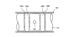
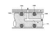
- FIG. 9 and FIG. 10 in a structure in which a flow path 130 through which fluid flows through two members 110 and 120 facing each other on curved surfaces is provided, the flow path 130 is sandwiched between the two members 110 and 120.
- two ring-shaped sealing members (O-rings) 140A and 140B are arranged to prevent fluid leakage between the two members 110 and 120 (for example, Japanese Patent Laid-Open No. 2006-307881). See FIG. 1 of the publication).
- the present invention is intended to provide a sealing structure capable of preventing fluid leakage while suppressing cost.
- the first member in which the first flow path is formed and the second member in which the second flow path is formed face each other with a curved surface, and the curved surface of the first member
- the first opening end of the first channel is formed and the second opening end of the second channel is formed on the curved surface of the second member.
- 1 is a sealing structure that prevents a fluid flowing through the first flow path and the second flow path from leaking between the first member and the second member. It is characterized by being arranged so as to surround the outer circumferences of both the first opening end and the second opening end while being sandwiched between one member and the second member.
- the seal member is preferably arranged coaxially with at least one of the first opening end and the second opening end.
- a groove for arranging the seal member is processed in at least one of the first member and the second member.
- the seal member is formed in an elliptical or rectangular ring shape in plan view so as to allow relative movement of the first member and the second member, and moves in the longitudinal direction thereof. It is preferable to arrange them in the same direction.
- one of the first member and the second member is a shaft member
- the other of the first member and the second member is a housing in which the shaft member is inserted.
- the sealing structure of the present invention it is not necessary to process a plurality of seal members and a plurality of seal member mounting grooves, and the number of parts of the seal member is reduced, and the groove processing is simplified, so that the fluid can be reliably manufactured at low cost. An excellent effect that leakage can be prevented can be obtained.
- This embodiment is a structure in which a flow path (a first flow path and a second flow path) through which fluid flows through two members (a first member and a second member) facing each other on a curved surface is provided. It is a sealing structure that prevents leakage of fluid from between members.
- one of the two members is a shaft member 10 and the other is a housing 20 in which the shaft member 10 is inserted.
- These two members are components such as an engine, a transmission, a power steering, or a switching valve mounted on an automobile, for example, and lubricating oil or hydraulic oil is used as a fluid.
- the devices and members provided with the two members as constituent elements are not limited to those described above, and the two members are not limited to the shaft member 10 or the housing 20.
- the two members are members having at least curved surfaces, and any member may be used as long as a flow path having an inlet or an outlet is formed on each curved surface, and at least the curved surfaces are opposed to each other.
- the fluid is not limited to lubricating oil or hydraulic oil, and may be other liquid such as water or gas.
- the shaft member 10 is formed with a flow path (hereinafter also referred to as a first flow path) 31 having an open end (hereinafter also referred to as a first open end) 31a serving as an inlet or an outlet.
- the housing 20 is formed with a flow path (hereinafter also referred to as a second flow path) 32 having an open end (hereinafter also referred to as a second open end) 32a serving as an inlet or an outlet.
- the first flow path 31 is formed by combining at least a flow path extending in the axial direction and a flow path connected to the flow path and extending in the radial direction.
- the second flow path 32 includes at least a flow path extending in the radial direction of the shaft member 10 in a state where the shaft member 10 is inserted into the housing 20.
- a series of flow paths 30 is formed through the shaft member 10 and the housing 20 by the first flow path 31 and the second flow path 32.
- the first opening end 31a and the second opening end 32a are formed on the curved surfaces of the shaft member 10 and the housing 20 that face each other. Furthermore, the first opening end 31a and the second opening end 32a are formed at opposing positions that are coaxial.
- the ring-shaped seal member 40 While being sandwiched between the curved surfaces of the shaft member 10 and the housing 20, the ring-shaped seal member 40 is disposed so as to surround the outer periphery of both the first opening end 31a and the second opening end 32a. .
- the seal member 40 is disposed coaxially with the first opening end 31a and the second opening end 32a.
- the seal member 40 is an elastic member (for example, an O-ring) that can be elastically deformed, and as the material, for example, synthetic rubber, synthetic resin, or a flexible metal can be used.
- the shape of the seal member 40 is not limited to a substantially rectangular cross section as shown in FIGS. 1 and 2, but a spherical cross section, a lip shape having a C-shaped cross section as shown in FIG.
- Various shapes such as a shape in which a rib-like protrusion is provided on the sealing surface as shown in a) and (b) can be adopted.
- the seal surface portions 40 a and 40 b expand in a direction away from each other by the internal pressure of the fluid, and the curved surfaces (wall surfaces) of the shaft member 10 and the housing 20 face each other. Adhering closely, sealing performance can be improved more.
- a groove 11 for arranging the seal member 40 is processed into a concave shape on the outer periphery of the first opening end 31a.
- the groove 11 has a circular shape in a top view as shown in FIG. 3 so as to match the position / shape of the first opening end 31a and the second opening end 32a and the shape of the seal member 40. Is formed.
- the shape of the groove 11 is not limited to this.
- sealing structure of the present invention is not limited to the above-described embodiment, and it is needless to say that various changes can be made without departing from the scope of the present invention.
- the groove 11 is processed into a circular shape when viewed from the top, but is, for example, elliptical or rectangular when viewed from the top, or a circular shape (circular or elliptical as shown in FIG. 6). Shape) or a rectangular ring shape.
- the open end 31 a of the flow path 31 on the shaft member 10 side and the open end 32 a of the flow path 32 on the housing 20 side can be brought close to each other. This is preferable in that the gap between the shaft member 10 and the housing 20 can be further reduced.
- the grooves 11 and 11 ′ are processed on the shaft member 10 side.
- the grooves 21 may be processed on the housing 20 side. That is, the seal member 40 may be grooved and attached to one of the shaft member 10 and the housing 20, or may be grooved and attached to both the shaft member 10 and the housing 20. It may be.
- the seal member 40 is disposed coaxially with both the open end 31a of the flow path 31 on the shaft member 10 side and the open end 32a of the flow path 32 on the housing 20 side. What is necessary is just to be arrange
- shaft member 10 and the housing 20 are relatively stationary.
- shaft member 10 and the housing 20 are relatively moved (shaft member). 10 and the housing 20 may be allowed to be misaligned).
- the groove 21 ′ is processed on the housing 20 side.
- the groove 21 ′ is formed on the outer periphery of the open end 32 a of the flow channel 32 in a concave shape coaxial with the open end 32 a of the flow channel 32, and in the moving direction as compared with the direction orthogonal to the moving direction of the shaft member 10. It is formed in a shape that extends long.
- the seal member 40 ′ is formed in an elliptical or rectangular ring shape in plan view, and is fitted in the groove 21 ′ with its longitudinal direction coinciding with the moving direction.
- the center position of the seal member 40 ′ is coaxial with the center position of the opening end 32 a of the flow path 32 on the housing 20 side, and deviates from the center position of the opening end 31 a of the flow path 31 on the shaft member 10 side. Allows to be placed.
- the groove 21 'on the housing 20 side has a circumferential direction as compared with the axial direction so as to allow the circumferential movement (for example, rocking) of the shaft member 10. And processed into a shape extending long along the line.
- an elliptical or rectangular ring-shaped member is used as the sealing member 40 'in plan view, and the sealing member 40' is mounted in the groove 21 'with its longitudinal direction coinciding with the circumferential direction.
- the groove 21 'on the housing 20 side is processed into a shape extending longer in the axial direction than in the circumferential direction so as to allow the axial movement of the shaft member 10. Shall be.
- an elliptical or rectangular ring-shaped member is used as the seal member 40 'in plan view, and the seal member 40' is mounted in the groove 21 'with its longitudinal direction coinciding with the axial direction.
- the opening end 31 a of the flow path 31 on the shaft member 10 side and the opening end 32 a of the flow path 32 on the housing 20 side are connected to the groove 21 ′ and Even when the seal member 40 ′ is displaced in the movement direction (circumferential direction or axial direction) within the range of the movement direction length (circumferential length or axial length), the opening end 31 a of the flow path 31.
- the open end 32a of the flow path 32 is surrounded by the seal member 40 'and communicates with the inside of the seal member 40', and the leakage of the fluid can be reliably prevented by the seal member 40 '.
- the sealing structure of the present invention can be used for manufacturing various devices and members that require prevention of fluid leakage, such as an engine, transmission, power steering, or switching valve mounted on an automobile.
Landscapes
- Engineering & Computer Science (AREA)
- General Engineering & Computer Science (AREA)
- Mechanical Engineering (AREA)
- Physics & Mathematics (AREA)
- Geometry (AREA)
- Gasket Seals (AREA)
- Sealing Devices (AREA)
Abstract
第1の流路31が形成された第1の部材10と第2の流路32が形成された第2の部材20とが互いに曲面で対向し、第1の部材10の前記曲面に第1の流路31の第1の開口端31aが形成されているとともに第2の部材20の前記曲面に第2の流路32の第2の開口端32aが形成されている構造において、リング状のシール部材40を、第1の開口端31aおよび第2の開口端32aの双方の外周を取り囲むようにして、第1の部材10および第2の部材20の前記曲面で挟んで配置する。この結果として、曲面で対向する二部材を通して流体が流れる流路が設けられてなる構造において、コストを抑制しながら上記二部材間からの流体の漏洩を防止することができる密封構造を提供する。
Description
本発明は、曲面で対向する二部材を通して流体が流れる流路が設けられてなる構造に用いて好適な、流体の漏洩を防止する密封構造に関する。
従来、図9および図10に示すように、曲面で対向する二部材110,120を通して流体が流れる流路130が設けられてなる構造においては、前記二部材110,120間に流路130を挟んで2個のリング状のシール部材(Oリング)140A,140Bを配置して、二部材110,120間からの流体の漏洩を防止することが一般的である(例えば、特開2006-307881号公報の図1参照)。
しかしながら、このような構造は複数個のシール部材140A,140Bを必要とし、また、シール部材140A,140Bを設置するための溝150A,150Bの加工も複数箇所に必要となるため、高価なものとなっていた。
本発明は、斯かる実情に鑑み、コストを抑制しながら流体の漏洩を防止することができる密封構造を提供しようとするものである。
本発明の密封構造は、第1の流路が形成された第1の部材と第2の流路が形成された第2の部材とが互いに曲面で対向し、前記第1の部材の前記曲面に前記第1の流路の第1の開口端が形成されているとともに前記第2の部材の前記曲面に前記第2の流路の第2の開口端が形成されている構造において、前記第1の流路および前記第2の流路を通して流れる流体が前記第1の部材および前記第2の部材の間から漏洩することを防止する密封構造であって、リング状のシール部材が、前記第1の部材および前記第2の部材に挟まれながら、前記第1の開口端および前記第2の開口端の双方の外周を取り囲むようにして配置されていることを特徴としている。
なお、前記シール部材は、前記第1の開口端および前記第2の開口端の少なくとも一方と同軸に配置されていることが好ましい。
また、前記第1の部材および前記第2の部材の少なくとも一方に、前記シール部材を配置するための溝が加工されていることが好ましい。
また、前記シール部材は、前記第1の部材および前記第2の部材の相対的な移動を許容するように、平面視で楕円状または長方形状のリング状に形成され、その長手方向を前記移動方向に一致させて配置されていることが好ましい。
また、前記第1の部材および前記第2の部材の一方は軸部材であり、前記第1の部材および前記第2の部材の他方は前記軸部材が内挿されるハウジングであることが好ましい。
本発明の密封構造によれば、複数個のシール部材と複数箇所のシール部材装着溝の加工が不要となり、シール部材の部品点数を削減するとともに、溝加工を簡略化し、廉価で確実に流体の漏洩を防止することができるという優れた効果を奏し得る。
以下、本発明の実施の形態を添付図面を参照して説明する。
本実施形態は、曲面で対向する二部材(第1の部材および第2の部材)を通して流体が流れる流路(第1の流路および第2の流路)が設けられてなる構造において、二部材間からの流体の漏洩を防止する密封構造である。
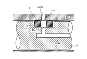
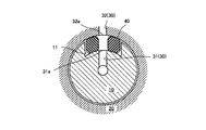
図1および図2に示すように、本密封構造では、二部材のうち一方を軸部材10とするとともに、他方を軸部材10が内挿されるハウジング20とする。これらの二部材は、例えば自動車に搭載されるエンジン、トランスミッション、パワーステアリング、あるいは切換バルブ等の構成要素であって、流体として潤滑油や作動油が用いられるものである。ただし、二部材を構成要素として備える機器や部材は上述のものに限定されず、また、二部材は軸部材10やハウジング20に限定されるものでもない。二部材は、少なくとも曲面を有する部材であって、各曲面上に入口または出口が開口する流路が形成され、少なくとも当該曲面が互いに対向するように配置される任意の部材であればよい。さらに、流体についても、潤滑油や作動油に限定されるものではなく、例えば水等の他の液体や、あるいは気体であってもよい。
軸部材10には、入口または出口となる開口端(以下、第1の開口端ともいう)31aを有する流路(以下、第1の流路ともいう)31が形成されている。また、ハウジング20には、入口または出口となる開口端(以下、第2の開口端ともいう)32aを有する流路(以下、第2の流路ともいう)32が形成されている。
第1の流路31は、軸方向に延びる流路と当該流路に接続されて径方向に延びる流路とを少なくとも組み合わせて形成されている。第2の流路32は、ハウジング20に軸部材10が内挿された状態で軸部材10の径方向に延びる流路を少なくとも備えて形成されている。第1の流路31および第2の流路32によって、軸部材10およびハウジング20を通して一連の流路30が形成される。
第1の開口端31aおよび第2の開口端32aは、軸部材10およびハウジング20の互いに対向する曲面上にそれぞれ開口して形成されている。さらに、第1の開口端31aおよび第2の開口端32aは、同軸となる対向する位置に形成されている。
このような軸部材10およびハウジング20の曲面に挟まれながら、第1の開口端31aおよび第2の開口端32aの双方の外周を取り囲むようにして、リング状のシール部材40が配置されている。シール部材40は、第1の開口端31aおよび第2の開口端32aと同軸に配置されている。
シール部材40は弾性変形可能な弾性部材(例えばOリング)であり、その素材としては、例えば合成ゴムや合成樹脂、あるいは柔軟性金属などを使用することが可能である。また、シール部材40の形状は、図1および図2に示すような断面略矩形状のほかに、断面球形状や、図4に示すような断面C字状のリップ形状、さらには図5(a)および(b)に示すようなシール面にリブ状の突起を設けた形状など、種々の形状を採用することが可能である。特に、図4に示すようなリップ形状のシール部材40によれば、流体の内圧でシール面部40a,40bが互いに離隔する方向に拡張し、軸部材10およびハウジング20の対向する曲面(壁面)により密着して、シール性能をより高めることができる。
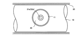
軸部材10には、シール部材40を配置するための溝11が、第1の開口端31aの外周に凹状に加工されている。溝11は、第1の開口端31aおよび第2の開口端32aの位置・形状とシール部材40の形状とに適合するように、本実施形態では図3に示すような上面視で正円状に形成されている。ただし、溝11の形状はこれに限定されるものではない。
本発明の一実施形態に係る密封構造は上述のように構成されているので、以下のような作用および効果を奏する。
本実施形態の密封構造は、軸部材10に溝11を一つ加工し、その溝11に一つのシール部材40を装着するだけとなっている。したがって、従来の密封構造のように複数個のシール部材および複数箇所の溝加工が不要となり、シール部材の部品点数を削減するとともに溝加工を簡略化することができ、廉価で確実に流体の漏洩を防止することができる。
なお、本発明の密封構造は、上述の実施形態に限定されるものではなく、本発明の要旨を逸脱しない範囲内において種々変更を加え得ることは勿論である。
例えば、上述の実施形態では、溝11は上面視で正円状に加工されているが、例えば上面視で楕円状や、矩形状や、あるいは図6に示すように円形(正円状や楕円状)乃至は矩形状のリング状に加工されていてもよい。例えばリング状の溝11′であれば、軸部材10側の流路31の開口端31aとハウジング20側の流路32の開口端32aとを接近させることができる。これは、軸部材10とハウジング20との間の隙間をより小さくできるという点で好ましい。
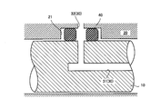
また、上述の実施形態では、軸部材10側に溝11,11′を加工したが、図7に示すように、ハウジング20側に溝21を加工してもよい。すなわち、シール部材40は、軸部材10およびハウジング20のうちのいずれか一方に溝加工して装着するようにしてもよいし、あるいは軸部材10およびハウジング20の両方に溝加工して装着するようにしてもよい。
また、上述の実施形態では、シール部材40は軸部材10側の流路31の開口端31aおよびハウジング20側の流路32の開口端32aの両方と同軸に配置されているが、少なくとも一方と同軸に配置されていればよい。
すなわち、上述の実施形態では、軸部材10およびハウジング20は相対的に静止しているものを想定しているが、変形例として、軸部材10およびハウジング20が相対的に移動するもの(軸部材10およびハウジング20の設置位置のズレを許容するものを含む)であってもよい。
例えば、図8(a)および(b)に示すように、軸部材10がハウジング20に対して移動するものとする。このとき、ハウジング20側に溝21′を加工する。溝21′は、流路32の開口端32aの外周に、流路32の開口端32aと同軸の凹状に形成されているとともに、軸部材10の移動方向に直交する方向に比べて移動方向に長く延びる形状に形成されている。そして、シール部材40′は、平面視で楕円状または長方形状のリング状に形成され、その長手方向を前記移動方向に一致させて溝21′内に装着されるようにする。これにより、シール部材40′の中心位置が、ハウジング20側の流路32の開口端32aの中心位置と同軸である一方、軸部材10側の流路31の開口端31aの中心位置からずれて配置されることを可能とする。
より具体的には、図8(a)に示すように、軸部材10の周方向の移動(例えば揺動)を許容するように、ハウジング20側において溝21′が軸方向に比べて周方向に沿って長く延びる形状に加工されたものとする。同時に、シール部材40′としては平面視で楕円状または長方形状のリング状のものを用い、その長手方向を周方向に一致させて溝21′内に装着するようにする。
また、図8(b)に示すように、軸部材10の軸方向の移動を許容するように、ハウジング20側において溝21′が周方向に比べて軸方向に沿って長く延びる形状に加工されたものとする。同時に、シール部材40′としては平面視で楕円状または長方形状のリング状のものを用い、その長手方向を軸方向に一致させて溝21′内に装着するようにする。
これによれば、溝21′内にシール部材40′を装着した際、軸部材10側の流路31の開口端31aとハウジング20側の流路32の開口端32aとが、溝21′およびシール部材40′の移動方向長さ(周方向長さまたは軸方向長さ)の範囲内で移動方向(周方向または軸方向)にずれている場合であっても、流路31の開口端31aおよび流路32の開口端32aはシール部材40′によって取り囲まれて、シール部材40′の内側を介して連通し、シール部材40′によって流体の漏洩を確実に防止することができる。
本発明の密封構造は、例えば自動車に搭載されるエンジン、トランスミッション、パワーステアリング、あるいは切換バルブ等の、流体の漏洩防止が必要とされる各種の機器や部材の製造に利用することができる。
Claims (5)
- 第1の流路が形成された第1の部材と第2の流路が形成された第2の部材とが互いに曲面で対向し、前記第1の部材の前記曲面に前記第1の流路の第1の開口端が形成されているとともに前記第2の部材の前記曲面に前記第2の流路の第2の開口端が形成されている構造において、前記第1の流路および前記第2の流路を通して流れる流体が前記第1の部材および前記第2の部材の間から漏洩することを防止する密封構造であって、
リング状のシール部材が、前記第1の部材および前記第2の部材に挟まれながら、前記第1の開口端および前記第2の開口端の双方の外周を取り囲むようにして配置されている
ことを特徴とする、密封構造。 - 前記シール部材は、前記第1の開口端および前記第2の開口端の少なくとも一方と同軸に配置されている
ことを特徴とする、請求の範囲1に記載の密封構造。 - 前記第1の部材および前記第2の部材の少なくとも一方に、前記シール部材を配置するための溝が加工されている
ことを特徴とする、請求の範囲1または2に記載の密封構造。 - 前記シール部材は、前記第1の部材および前記第2の部材の相対的な移動を許容するように、平面視で楕円状または長方形状のリング状に形成され、その長手方向を前記移動方向に一致させて配置されている
ことを特徴とする、請求の範囲1~3のいずれか1項に記載の密封構造。 - 前記第1の部材および前記第2の部材の一方は軸部材であり、
前記第1の部材および前記第2の部材の他方は前記軸部材が内挿されるハウジングである
ことを特徴とする、請求の範囲1~4のいずれか1項に記載の密封構造。
Applications Claiming Priority (2)
| Application Number | Priority Date | Filing Date | Title |
|---|---|---|---|
| JP2011023096A JP2012163144A (ja) | 2011-02-04 | 2011-02-04 | 密封構造 |
| JP2011-023096 | 2011-02-04 |
Publications (1)
| Publication Number | Publication Date |
|---|---|
| WO2012105638A1 true WO2012105638A1 (ja) | 2012-08-09 |
Family
ID=46602844
Family Applications (1)
| Application Number | Title | Priority Date | Filing Date |
|---|---|---|---|
| PCT/JP2012/052344 Ceased WO2012105638A1 (ja) | 2011-02-04 | 2012-02-02 | 密封構造 |
Country Status (2)
| Country | Link |
|---|---|
| JP (1) | JP2012163144A (ja) |
| WO (1) | WO2012105638A1 (ja) |
Cited By (1)
| Publication number | Priority date | Publication date | Assignee | Title |
|---|---|---|---|---|
| CN110319193A (zh) * | 2019-07-24 | 2019-10-11 | 西安蓝天石化设备有限公司 | 一种高压曲面环形密封结构 |
Families Citing this family (1)
| Publication number | Priority date | Publication date | Assignee | Title |
|---|---|---|---|---|
| DE102018206477B3 (de) * | 2018-04-26 | 2019-02-07 | Robert Bosch Gmbh | Vorrichtung zur Abdichtung zweier mit unterschiedlichen Fluiden gefüllter Räume bei einer MEMS-Sensoranordnung |
Citations (2)
| Publication number | Priority date | Publication date | Assignee | Title |
|---|---|---|---|---|
| JPS6289568U (ja) * | 1985-11-25 | 1987-06-08 | ||
| JPH0560246A (ja) * | 1991-08-28 | 1993-03-09 | Mitsubishi Heavy Ind Ltd | 摺動シール装置 |
-
2011
- 2011-02-04 JP JP2011023096A patent/JP2012163144A/ja not_active Withdrawn
-
2012
- 2012-02-02 WO PCT/JP2012/052344 patent/WO2012105638A1/ja not_active Ceased
Patent Citations (2)
| Publication number | Priority date | Publication date | Assignee | Title |
|---|---|---|---|---|
| JPS6289568U (ja) * | 1985-11-25 | 1987-06-08 | ||
| JPH0560246A (ja) * | 1991-08-28 | 1993-03-09 | Mitsubishi Heavy Ind Ltd | 摺動シール装置 |
Cited By (1)
| Publication number | Priority date | Publication date | Assignee | Title |
|---|---|---|---|---|
| CN110319193A (zh) * | 2019-07-24 | 2019-10-11 | 西安蓝天石化设备有限公司 | 一种高压曲面环形密封结构 |
Also Published As
| Publication number | Publication date |
|---|---|
| JP2012163144A (ja) | 2012-08-30 |
Similar Documents
| Publication | Publication Date | Title |
|---|---|---|
| KR102143056B1 (ko) | 오일 시일 | |
| EP3412941B1 (en) | Gasket | |
| CN104704270B (zh) | 密封垫 | |
| US20110278799A1 (en) | Seal ring | |
| US9856984B2 (en) | Sealing device | |
| CN111788420B (zh) | 密封装置和流体控制阀 | |
| JP6356373B1 (ja) | 密封装置 | |
| CN103403413B (zh) | 密封装置 | |
| JP2008190504A (ja) | 軸シール保持用リング | |
| WO2012105638A1 (ja) | 密封構造 | |
| KR102437869B1 (ko) | 시일 및 시일 기구 | |
| RU2637154C2 (ru) | Наклонные сопряженные поверхности в сборке клапана | |
| RU2626873C2 (ru) | Уплотнительный элемент для трубопроводной арматуры | |
| WO2016121709A1 (ja) | ライニング型バタフライバルブ | |
| JP2018071554A (ja) | 流路切替弁 | |
| WO2016163096A1 (ja) | バルブ装置 | |
| WO2024018751A1 (ja) | 密封構造 | |
| CN102913621B (zh) | 碳密封件o型环腔尺寸设置 | |
| JP6633776B2 (ja) | メカニカルシール装置 | |
| WO2014012496A1 (en) | Sealing device in a valve and a valve with the same | |
| JP2023124526A (ja) | 軸シール部材及びシール構造 | |
| WO2011024522A1 (ja) | コンタミシール装置 | |
| CN106481786B (zh) | 双离合变速箱及其密封装置 | |
| CN220228010U (zh) | 一种适用于高压和负压工况的双向气动阀门 | |
| JP2016070473A (ja) | バタフライ弁用のシートリング及バタフライ弁 |
Legal Events
| Date | Code | Title | Description |
|---|---|---|---|
| 121 | Ep: the epo has been informed by wipo that ep was designated in this application |
Ref document number: 12742324 Country of ref document: EP Kind code of ref document: A1 |
|
| NENP | Non-entry into the national phase |
Ref country code: DE |
|
| 122 | Ep: pct application non-entry in european phase |
Ref document number: 12742324 Country of ref document: EP Kind code of ref document: A1 |