WO2012105041A1 - ハイブリッド車両 - Google Patents
ハイブリッド車両 Download PDFInfo
- Publication number
- WO2012105041A1 WO2012105041A1 PCT/JP2011/052370 JP2011052370W WO2012105041A1 WO 2012105041 A1 WO2012105041 A1 WO 2012105041A1 JP 2011052370 W JP2011052370 W JP 2011052370W WO 2012105041 A1 WO2012105041 A1 WO 2012105041A1
- Authority
- WO
- WIPO (PCT)
- Prior art keywords
- engine
- hybrid vehicle
- stop
- during
- transition
- Prior art date
- Legal status (The legal status is an assumption and is not a legal conclusion. Google has not performed a legal analysis and makes no representation as to the accuracy of the status listed.)
- Ceased
Links
Images


Classifications
-
- B—PERFORMING OPERATIONS; TRANSPORTING
- B60—VEHICLES IN GENERAL
- B60W—CONJOINT CONTROL OF VEHICLE SUB-UNITS OF DIFFERENT TYPE OR DIFFERENT FUNCTION; CONTROL SYSTEMS SPECIALLY ADAPTED FOR HYBRID VEHICLES; ROAD VEHICLE DRIVE CONTROL SYSTEMS FOR PURPOSES NOT RELATED TO THE CONTROL OF A PARTICULAR SUB-UNIT
- B60W20/00—Control systems specially adapted for hybrid vehicles
- B60W20/40—Controlling the engagement or disengagement of prime movers, e.g. for transition between prime movers
-
- B—PERFORMING OPERATIONS; TRANSPORTING
- B60—VEHICLES IN GENERAL
- B60K—ARRANGEMENT OR MOUNTING OF PROPULSION UNITS OR OF TRANSMISSIONS IN VEHICLES; ARRANGEMENT OR MOUNTING OF PLURAL DIVERSE PRIME-MOVERS IN VEHICLES; AUXILIARY DRIVES FOR VEHICLES; INSTRUMENTATION OR DASHBOARDS FOR VEHICLES; ARRANGEMENTS IN CONNECTION WITH COOLING, AIR INTAKE, GAS EXHAUST OR FUEL SUPPLY OF PROPULSION UNITS IN VEHICLES
- B60K6/00—Arrangement or mounting of plural diverse prime-movers for mutual or common propulsion, e.g. hybrid propulsion systems comprising electric motors and internal combustion engines
- B60K6/20—Arrangement or mounting of plural diverse prime-movers for mutual or common propulsion, e.g. hybrid propulsion systems comprising electric motors and internal combustion engines the prime-movers consisting of electric motors and internal combustion engines, e.g. HEVs
- B60K6/42—Arrangement or mounting of plural diverse prime-movers for mutual or common propulsion, e.g. hybrid propulsion systems comprising electric motors and internal combustion engines the prime-movers consisting of electric motors and internal combustion engines, e.g. HEVs characterised by the architecture of the hybrid electric vehicle
- B60K6/44—Series-parallel type
- B60K6/445—Differential gearing distribution type
-
- B—PERFORMING OPERATIONS; TRANSPORTING
- B60—VEHICLES IN GENERAL
- B60W—CONJOINT CONTROL OF VEHICLE SUB-UNITS OF DIFFERENT TYPE OR DIFFERENT FUNCTION; CONTROL SYSTEMS SPECIALLY ADAPTED FOR HYBRID VEHICLES; ROAD VEHICLE DRIVE CONTROL SYSTEMS FOR PURPOSES NOT RELATED TO THE CONTROL OF A PARTICULAR SUB-UNIT
- B60W10/00—Conjoint control of vehicle sub-units of different type or different function
- B60W10/04—Conjoint control of vehicle sub-units of different type or different function including control of propulsion units
- B60W10/06—Conjoint control of vehicle sub-units of different type or different function including control of propulsion units including control of combustion engines
-
- B—PERFORMING OPERATIONS; TRANSPORTING
- B60—VEHICLES IN GENERAL
- B60W—CONJOINT CONTROL OF VEHICLE SUB-UNITS OF DIFFERENT TYPE OR DIFFERENT FUNCTION; CONTROL SYSTEMS SPECIALLY ADAPTED FOR HYBRID VEHICLES; ROAD VEHICLE DRIVE CONTROL SYSTEMS FOR PURPOSES NOT RELATED TO THE CONTROL OF A PARTICULAR SUB-UNIT
- B60W10/00—Conjoint control of vehicle sub-units of different type or different function
- B60W10/04—Conjoint control of vehicle sub-units of different type or different function including control of propulsion units
- B60W10/08—Conjoint control of vehicle sub-units of different type or different function including control of propulsion units including control of electric propulsion units, e.g. motors or generators
-
- B—PERFORMING OPERATIONS; TRANSPORTING
- B60—VEHICLES IN GENERAL
- B60W—CONJOINT CONTROL OF VEHICLE SUB-UNITS OF DIFFERENT TYPE OR DIFFERENT FUNCTION; CONTROL SYSTEMS SPECIALLY ADAPTED FOR HYBRID VEHICLES; ROAD VEHICLE DRIVE CONTROL SYSTEMS FOR PURPOSES NOT RELATED TO THE CONTROL OF A PARTICULAR SUB-UNIT
- B60W20/00—Control systems specially adapted for hybrid vehicles
-
- B—PERFORMING OPERATIONS; TRANSPORTING
- B60—VEHICLES IN GENERAL
- B60W—CONJOINT CONTROL OF VEHICLE SUB-UNITS OF DIFFERENT TYPE OR DIFFERENT FUNCTION; CONTROL SYSTEMS SPECIALLY ADAPTED FOR HYBRID VEHICLES; ROAD VEHICLE DRIVE CONTROL SYSTEMS FOR PURPOSES NOT RELATED TO THE CONTROL OF A PARTICULAR SUB-UNIT
- B60W30/00—Purposes of road vehicle drive control systems not related to the control of a particular sub-unit, e.g. of systems using conjoint control of vehicle sub-units
- B60W30/18—Propelling the vehicle
- B60W30/192—Mitigating problems related to power-up or power-down of the driveline, e.g. start-up of a cold engine
-
- B—PERFORMING OPERATIONS; TRANSPORTING
- B60—VEHICLES IN GENERAL
- B60W—CONJOINT CONTROL OF VEHICLE SUB-UNITS OF DIFFERENT TYPE OR DIFFERENT FUNCTION; CONTROL SYSTEMS SPECIALLY ADAPTED FOR HYBRID VEHICLES; ROAD VEHICLE DRIVE CONTROL SYSTEMS FOR PURPOSES NOT RELATED TO THE CONTROL OF A PARTICULAR SUB-UNIT
- B60W30/00—Purposes of road vehicle drive control systems not related to the control of a particular sub-unit, e.g. of systems using conjoint control of vehicle sub-units
- B60W30/18—Propelling the vehicle
- B60W30/20—Reducing vibrations in the driveline
-
- B—PERFORMING OPERATIONS; TRANSPORTING
- B60—VEHICLES IN GENERAL
- B60W—CONJOINT CONTROL OF VEHICLE SUB-UNITS OF DIFFERENT TYPE OR DIFFERENT FUNCTION; CONTROL SYSTEMS SPECIALLY ADAPTED FOR HYBRID VEHICLES; ROAD VEHICLE DRIVE CONTROL SYSTEMS FOR PURPOSES NOT RELATED TO THE CONTROL OF A PARTICULAR SUB-UNIT
- B60W30/00—Purposes of road vehicle drive control systems not related to the control of a particular sub-unit, e.g. of systems using conjoint control of vehicle sub-units
- B60W30/18—Propelling the vehicle
- B60W30/20—Reducing vibrations in the driveline
- B60W2030/206—Reducing vibrations in the driveline related or induced by the engine
-
- B—PERFORMING OPERATIONS; TRANSPORTING
- B60—VEHICLES IN GENERAL
- B60W—CONJOINT CONTROL OF VEHICLE SUB-UNITS OF DIFFERENT TYPE OR DIFFERENT FUNCTION; CONTROL SYSTEMS SPECIALLY ADAPTED FOR HYBRID VEHICLES; ROAD VEHICLE DRIVE CONTROL SYSTEMS FOR PURPOSES NOT RELATED TO THE CONTROL OF A PARTICULAR SUB-UNIT
- B60W2710/00—Output or target parameters relating to a particular sub-units
- B60W2710/06—Combustion engines, Gas turbines
- B60W2710/0644—Engine speed
-
- B—PERFORMING OPERATIONS; TRANSPORTING
- B60—VEHICLES IN GENERAL
- B60W—CONJOINT CONTROL OF VEHICLE SUB-UNITS OF DIFFERENT TYPE OR DIFFERENT FUNCTION; CONTROL SYSTEMS SPECIALLY ADAPTED FOR HYBRID VEHICLES; ROAD VEHICLE DRIVE CONTROL SYSTEMS FOR PURPOSES NOT RELATED TO THE CONTROL OF A PARTICULAR SUB-UNIT
- B60W2710/00—Output or target parameters relating to a particular sub-units
- B60W2710/06—Combustion engines, Gas turbines
- B60W2710/0644—Engine speed
- B60W2710/0661—Speed change rate
-
- Y—GENERAL TAGGING OF NEW TECHNOLOGICAL DEVELOPMENTS; GENERAL TAGGING OF CROSS-SECTIONAL TECHNOLOGIES SPANNING OVER SEVERAL SECTIONS OF THE IPC; TECHNICAL SUBJECTS COVERED BY FORMER USPC CROSS-REFERENCE ART COLLECTIONS [XRACs] AND DIGESTS
- Y02—TECHNOLOGIES OR APPLICATIONS FOR MITIGATION OR ADAPTATION AGAINST CLIMATE CHANGE
- Y02T—CLIMATE CHANGE MITIGATION TECHNOLOGIES RELATED TO TRANSPORTATION
- Y02T10/00—Road transport of goods or passengers
- Y02T10/60—Other road transportation technologies with climate change mitigation effect
- Y02T10/62—Hybrid vehicles
-
- Y—GENERAL TAGGING OF NEW TECHNOLOGICAL DEVELOPMENTS; GENERAL TAGGING OF CROSS-SECTIONAL TECHNOLOGIES SPANNING OVER SEVERAL SECTIONS OF THE IPC; TECHNICAL SUBJECTS COVERED BY FORMER USPC CROSS-REFERENCE ART COLLECTIONS [XRACs] AND DIGESTS
- Y10—TECHNICAL SUBJECTS COVERED BY FORMER USPC
- Y10S—TECHNICAL SUBJECTS COVERED BY FORMER USPC CROSS-REFERENCE ART COLLECTIONS [XRACs] AND DIGESTS
- Y10S903/00—Hybrid electric vehicles, HEVS
- Y10S903/902—Prime movers comprising electrical and internal combustion motors
- Y10S903/903—Prime movers comprising electrical and internal combustion motors having energy storing means, e.g. battery, capacitor
Definitions
- the present invention relates to a control apparatus for a hybrid vehicle including an engine and a motor as a power source, and more particularly to vibration suppression when starting and stopping an engine mounted on the hybrid vehicle.
- Patent Document 2 what is disclosed in Patent Document 2 is that a constant torque that is less than the torque required to continuously rotate the engine while the engine is stopped is output for a certain period of time, so that the crankshaft position of the engine Prepositioning is performed so that it is positioned on the shaft. Further, in the device disclosed in Patent Document 3, a fastening element is interposed between the engine and the motor generator. Then, a holding engagement capacity is set according to the torque required to raise the engine from the stopped state to the rotation speed synchronized with the rotation speed of the motor generator within the target start time. Is raised to the holding fastening capacity with a predetermined gradient.
- An object of the present invention is to suppress engine vibration without restarting the engine during the engine stop transition and preventing the engine rotation speed from staying in the resonance band for a long time.
- the present invention outputs the power generated from the engine and the motor generator to the drive shaft via the power transmission mechanism and easily causes a resonance phenomenon of the engine during the engine start.
- a control unit that controls the engine not to be restarted during the transition It is characterized by providing.
- the power generated from the engine and the motor generator is output to the drive shaft via the power transmission mechanism, and the engine speed at which the engine resonance phenomenon easily occurs during engine startup.
- a control means is provided for controlling the engine not to be restarted during the transition. . Accordingly, since the engine is not restarted during the engine stop transition, it is possible to prevent the engine rotation speed from staying in the resonance band for a long time. As a result, engine vibration can be suppressed.
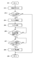
- FIG. 1 is a flowchart for engine restart control of a hybrid vehicle control device.
- FIG. 2 is a system configuration diagram of a hybrid vehicle control device.
- FIG. 3 is a time chart showing the transition of time and engine speed.
- FIG. 4 is a flowchart for engine stop control of the hybrid vehicle control apparatus.
- reference numeral 1 denotes a hybrid vehicle control device (not shown), that is, a four-shaft power input / output device to which the present invention is applied.
- the hybrid vehicle control device also referred to as “power input / output device” 1 uses an output from an engine (also referred to as “E / G” or “ENG”) 2 and an electric motor, as shown in FIG.
- an output shaft 3 of the engine 2 that generates a driving force by combustion of fuel as a driving system, and a first motor generator that generates a driving force by electricity and generates electric energy by driving (Also referred to as “MG1” or “first motor”) 5 and a second motor generator (also referred to as “MG2” or “second motor”) 6 and a drive shaft connected to drive wheels 7 of the hybrid vehicle.
- MG1 motor generator
- MG2 second motor generator
- PG1 first planetary gear
- 10 10
- a one-way clutch 4 to prevent the reverse rotation of the output shaft 3.
- the engine 2 includes an air amount adjusting means 11 such as a throttle valve for adjusting the amount of air to be sucked in accordance with the accelerator opening (the amount of depression of the accelerator pedal), and fuel injection for supplying fuel corresponding to the amount of air to be sucked in.
- Fuel supply means 12 such as a valve and ignition means 13 such as an ignition device for igniting the fuel are provided.
- the engine 2 is controlled in the combustion state of the fuel by the air amount adjusting means 11, the fuel supply means 12, and the ignition means 13, and generates a driving force by the combustion of the fuel.
- the first planetary gear 9 includes a first planetary carrier (also referred to as “C1”) 9-1, a first ring gear 9-2, a first sun gear 9-3, An output gear 14 having a first pinion gear 9-4 and communicating with the drive shaft 8 of the drive wheel 7, and a power transmission mechanism (“gear”) comprising a gear, a chain, or the like connecting the output gear 14 to the drive shaft 8. It is also referred to as “mechanism” or “differential gear mechanism”) 15.
- the second planetary gear 10 includes a second planetary carrier (also referred to as “C2”) 10-1, a second ring gear 10-2, a second sun gear 10-3, 2 pinion gear 10-4.
- the first planetary carrier 9-1 of the first planetary gear 9 and the second sun gear 10-3 of the second planetary gear 10 are coupled and connected to the output shaft 3 of the engine 2. Further, as shown in FIG. 2, the first ring gear 9-2 of the first planetary gear 9 and the second planetary carrier 10-1 of the second planetary gear 10 are coupled to communicate with the drive shaft 8. Connect to output gear 14.
- the first motor generator 5 includes a first motor rotor 5-1, a first motor stator 5-2, and a first motor rotor shaft 5-3
- the second motor generator 6 includes a second motor rotor. 6-1, a second motor stator 6-2, and a second motor rotor shaft 6-3.
- the first motor rotor 5-1 of the first motor generator 5 is connected to the first sun gear 9-3 of the first planetary gear 9, and the second ring gear 10- of the second planetary gear 10 is connected.
- 2 is connected to the second motor rotor 6-1 of the second motor generator 6.
- the hybrid vehicle has four elements composed of the engine 2, the first motor generator 5, the second motor generator 6, and the output gear 14 on a collinear diagram (not shown).
- the power transmission mechanism 15 is connected so that the first motor generator 5, the engine 2, the output gear 14, and the second motor generator 6 are arranged in this order. Accordingly, power is transferred between the engine 2, the first motor generator 5, the second motor generator 6, and the drive shaft 8.
- first inverter 16 is connected to the first motor stator 5-2 of the first motor generator 5, and the second inverter 17 is connected to the second motor stator 6-2 of the second motor generator 6. .
- the first and second motor generators 5 and 6 are controlled by the first and second inverters 16 and 17, respectively.
- the power terminals of the first and second inverters 16 and 17 are connected to a battery 19 as a power storage device through a bidirectional DCDC inverter 18, respectively.
- the hybrid vehicle control device 1 controls driving of the vehicle using outputs from the engine 2 and the first and second motor generators 5 and 6.
- the air amount adjustment means 11, the fuel supply means 12, the ignition means 13, the inverter 16, and the inverter 17 of the engine 2 are the control system of the control apparatus 1 for the hybrid vehicle.
- the drive control unit 20 includes an accelerator opening degree detection means 21, a vehicle speed detection means 22, a battery charge state detection means 23, and an engine rotation speed detection means 24. .
- the hybrid vehicle control device 1 outputs the power generated from the engine 2 and the first and second motor generators 5 and 6 to the drive shaft 8 via the power transmission mechanism 15.
- the transition It has the structure provided with the control means 25 which controls so that the said engine 2 may not be restarted inside.
- the drive control unit 20 of the hybrid vehicle control device 1 includes the control means 25 as shown in FIG. 2, and the control means 25 is in a state where the engine is stopped due to the engine stop determination. Is to temporarily stop the engine 2 regardless of whether the engine 2 is requested to be restarted.
- the engine since the engine is not restarted during the engine stop transition, it is possible to prevent the engine rotation speed from staying in the resonance band for a long time. As a result, engine vibration can be suppressed.
- control means 25 performs control so that the engine 2 is not restarted until a preset first time has elapsed even after the engine is stopped. That is, when there is an engine start request before the engine is stopped, the control means 25 restarts the engine 2 after the first time has elapsed since the engine stop. Accordingly, since the engine is not restarted until a predetermined time has elapsed after the engine is stopped, it is possible to reliably prevent the engine rotation speed from staying in the resonance band for a long time. As a result, engine vibration can be suppressed.
- control means 25 performs control so that the engine 2 is not stopped until a preset second time has elapsed after engine start. Therefore, even when the engine is started and stopped repeatedly, it is possible to prevent the engine rotation speed from staying in the resonance band for a long time. As a result, engine vibration can be suppressed.
- the accelerator opening detection signal from the accelerator opening detecting means 21 comprising an accelerator opening sensor and a vehicle speed sensor.
- the process proceeds to step (102) in which various signals such as an engine start / stop request value and a first time after the engine stop, which are used for this control, are captured. Then, after step (102) for taking in various signals, the process proceeds to step (103) for determining whether or not an engine stop request has been made.
- step (103) for determining whether or not there has been an engine stop request if the determination is YES, the process proceeds to step (104) for stopping the engine, and if the determination is NO, a return (described later) 109). Further, after shifting to the step (104) for stopping the engine, the engine 2 is stopped, and the routine proceeds to step (105) for reading the engine stop flag. Then, the above-described engine 2 is stopped, and the process proceeds from step (105) for reading the engine stop flag to step (106) for determining whether or not the first time has elapsed.
- step (106) for determining whether or not the first time has elapsed from the step (105) for reading the engine stop flag when the engine 2 is stopped if the determination is NO, this step If the determination in (106) is YES, that is, the determination is repeated until the first time elapses after the engine is stopped. If the determination is YES, the process proceeds to the step (104) for stopping the engine described above. Then, the process proceeds to step (107) in which it is determined whether or not there has been an engine start request.
- step (107) in which it is determined whether or not there has been an engine start request since the transition to step (104) for stopping the engine, if the determination is NO, the determination in step (107) is The determination is repeated until YES, and if the determination is YES, the routine proceeds to step (108) where the engine 2 is started, that is, restarted. Then, after the start (108) of starting the engine 2, that is, restarting, the routine proceeds to return (109).
- the hybrid vehicle control device 1 moves to the engine stop transition start position (Pa) in step (104), and the engine stop completion position even if there is an engine restart request thereafter.
- the process proceeds to (Pb).
- the engine start start position (Pc) is set. Therefore, as apparent from FIG. 3, the engine speed of the control according to the present invention indicated by the solid line reduces the time spent in the resonance band of the engine 2 as compared with the engine speed of the conventional control indicated by the broken line. .
- an accelerator opening detection signal from the accelerator opening detecting means 21 including an accelerator opening sensor or a vehicle speed sensor is used.
- the process proceeds to step (202) for taking in various signals such as the engine start / stop request value and the second time after engine start used in this control. Then, after the step (202) for capturing various signals, the process proceeds to a step (203) for determining whether or not an engine start request has been made.
- step (203) for determining whether or not there has been an engine stop request if the determination is YES, the process proceeds to step (204) for starting the engine. If the determination is NO, a return (described later) 209). Further, after the transition to the step (204) for starting the engine, the engine 2 is started, and the routine proceeds to a step (205) for reading the engine start flag. Then, the process proceeds to step (206) for determining whether or not the second time has elapsed since the engine 2 was started.
- step (206) for determining whether or not the second time has elapsed since the start of the engine 2 if the determination is NO, the determination in this step (206) is YES, that is, the engine The determination is repeated until the second time has elapsed since the start of No. 2, and if the determination is YES, whether or not there has been an engine stop request so far after shifting to the above-described step (204) for starting the engine The process proceeds to step (207) for determining whether or not.
- step (207) in which it is determined whether or not there has been an engine stop request so far after the transition to step (204) for starting the engine, if the determination is NO, the determination in step (207) is The determination is repeated until YES, and if the determination is YES, the process proceeds to step (208) for starting the stop of the engine 2. Then, after step (208) for starting the stop of the engine 2, the routine proceeds to return (209).
- the present invention has the following configurations (1) to (3).
- (1) A control device that does not restart an engine even when an engine restart request is made during an engine stop transition.
- (2) The control device according to (1), wherein the engine is not restarted unless the first time has elapsed even after the engine is stopped.
- (3) the engine is not limited to only when the engine is stopped, and even if there is a request for stopping the engine during engine cranking, the engine is started and the second time elapses.
- the time during which the engine speed stays in the resonance band is shortened, and even when the engine is repeatedly started and stopped, the start / stop request is not accepted unless the predetermined time has elapsed. It is possible to minimize the time during which the engine speed stays in the resonance band, and as a result, it is possible to suppress engine vibration.
- Control device for hybrid vehicle also referred to as “power input / output device”
- Engine also described as “E / G” or “ENG”
- Output shaft 4
- One-way clutch 5
- First motor generator also referred to as “MG1” or “first electric motor”
- Second motor generator also referred to as “MG2” or “second electric motor”
- Drive Wheel 8
- Shaft 9
- First Planetary Gear also referred to as “PG1”
- Second planetary gear also referred to as “PG2”)
- Air quantity adjustment means 12
- Fuel supply means 13
- Ignition means 14
- Output gear 15
- Power transmission mechanism 16 1st inverter 17 2nd inverter 18
- Bidirectional DCDC inverter 19
- Battery 20 Drive control part
- Accelerator opening degree detection means 22
- Vehicle speed detection means 23
- Battery charge state detection means 24
- Engine rotation speed detection means 25
Landscapes
- Engineering & Computer Science (AREA)
- Transportation (AREA)
- Mechanical Engineering (AREA)
- Chemical & Material Sciences (AREA)
- Combustion & Propulsion (AREA)
- Automation & Control Theory (AREA)
- Control Of Vehicle Engines Or Engines For Specific Uses (AREA)
- Hybrid Electric Vehicles (AREA)
- Output Control And Ontrol Of Special Type Engine (AREA)
- Electric Propulsion And Braking For Vehicles (AREA)
Abstract
Description
また、ハイブリッド車両においては、エンジン始動中にエンジンの共振現象の生じ易い回転数領域を短時間で通過させる先願がある。
例えば、特許文献1に開示されるものは、内燃機関の始動指示がなされた時に、エンジンの回転数が共振現象の生じ易い回転数領域の上限値として設定された共振基準回転数より小さい時には、モータのクランキングトルクを最大にしている。
また、特許文献2に開示されるものは、エンジンの停止中にエンジンを連続回転させるのに要するトルクに満たない一定トルクを一定時間だけ出力させることによって、エンジンのクランク軸位置を、所定のクランク軸に位置付けるようにプリポジショニングを行っている。
更に、特許文献3に開示されるものは、エンジンとモータジェネレータとの間に締結要素が介装されている。そして、目標始動時間内にエンジンを停止状態からモータジェネレータの回転数と同期する回転数まで引き上げるのに必要なトルクに応じた保持締結容量を設定し、エンジンを始動する時には、締結要素の締結容量を所定勾配で前記保持締結容量まで上昇させている。
このようにエンジン回転数が共振帯内のときに発生する振動が運転者に対して不快感を与えるために、エンジン回転数を共振帯から素早く通過させることが望ましい。
しかし、この従来技術はエンジングランキング中にエンジン停止要求があるときや、エンジン停止移行中に再始動要求があったときに関しては何ら記載されておらず、このような場合、エンジン回転数が共振帯に長時間とどまるために、振動が発生してしまうという不都合がある。
従って、エンジン停止移行中にはエンジンを再始動させないため、エンジン回転数が共振帯にとどまる時間が長くならないようにすることができる。
この結果、エンジン振動を抑制することができる。
図2において、1は図示しないハイブリッド車両の制御装置、つまり、本発明が適用される4軸式の動力入出力装置である。
前記ハイブリッド車両の制御装置(「動力入出力装置」ともいう。)1は、図2に示す如く、エンジン(「E/G」、「ENG」とも記載する。)2と電動機からの出力を用いて車両を駆動制御するために、駆動系として、燃料の燃焼により駆動力を発生させるエンジン2の出力軸3と、電気により駆動力を発生するとともに駆動により電気エネルギを発生する第一のモータジェネレータ(「MG1」、「第1電動機」ともいう。)5及び第二のモータジェネレータ(「MG2」、「第2電動機」ともいう。)6と、ハイブリッド車両の駆動輪7に接続される駆動軸8と、出力軸3と、第一のモータジェネレータ5と、第二のモータジェネレータ6と、駆動軸8にそれぞれ連結された第1プラネタリギヤ(「PG1」とも記載する。)9及び第2プラネタリギヤ(「PG2」とも記載する。)10と、出力軸3の逆転を防止するワンウェイクラッチ4とを備えている。
前記エンジン2は、空気量調整手段11と燃料供給手段12と着火手段13とにより燃料の燃焼状態を制御され、燃料の燃焼により駆動力を発生する。
また、前記第2プラネタリギヤ10は、図2に示す如く、第2プラネタリキャリア(「C2」とも記載する。)10-1と、第2リングギヤ10-2と、第2サンギヤ10-3と、第2ピニオンギヤ10-4とを有している。
そして、図2に示す如く、前記第1プラネタリギヤ9の第1プラネタリキャリア9-1と前記第2プラネタリギヤ10の第2サンギヤ10-3とを結合してエンジン2の出力軸3に接続する。
また、図2に示す如く、前記第1プラネタリギヤ9の第1リングギヤ9-2と前記第2プラネタリギヤ10の第2プラネタリキャリア10-1とを結合して前記駆動軸8に連絡する出力部材である出力ギヤ14に接続する。
そして、図2に示す如く、前記第1プラネタリギヤ9の第1サンギヤ9-3に前記第一のモータジェネレータ5の第1モータロータ5-1を接続し、前記第2プラネタリギヤ10の第2リングギヤ10-2に前記第二のモータジェネレータ6の第2モータロータ6-1を接続する。
つまり、前記ハイブリッド車両は、前記エンジン2と前記第一のモータジェネレータ5と前記第二のモータジェネレータ6と前記出力ギヤ14とから構成される4つの要素を、共線図(図示せず)上で、前記第一のモータジェネレータ5、前記エンジン2、前記出力ギヤ14、前記第二のモータジェネレータ6の順になるように連結した前記動力伝達機構15を備えている。
従って、前記エンジン2と前記第一のモータジェネレータ5と前記第二のモータジェネレータ6と前記駆動軸8との間で動力の授受が行われる。
そして、これらの第1、第2インバータ16、17により前記第一及び第二のモータジェネレータ5、6を夫々制御する。
また、前記第1、第2インバータ16、17の電源端子は、双方向DCDCインバータ18を通して、蓄電装置であるバッテリ19に夫々接続する。
このとき、前記ハイブリッド車両の制御装置1において、前記エンジン2の空気量調整手段11や燃料供給手段12、着火手段13、前記インバータ16、前記インバータ17は、前記ハイブリッド車両の制御装置1の制御系である駆動制御部20に接続されている。
また、この駆動制御部20には、図2に示す如く、アクセル開度検出手段21と、車両速度検出手段22と、バッテリ充電状態検出手段23と、エンジン回転速度検出手段24とを備えている。
詳述すれば、前記ハイブリッド車両の制御装置1の駆動制御部20は、図2に示す如く、前記制御手段25を備えており、この制御手段25は、エンジン停止判定によりエンジン停止移行中の場合は、前記エンジン2を再始動要求の有無に関わらず、一旦エンジン2を停止させるものである。
これにより、エンジン停止移行中にはエンジンを再始動させないため、エンジン回転数が共振帯にとどまる時間が長くならないようにすることができる。
この結果、エンジン振動を抑制することができる。
つまり、前記制御手段25は、エンジン停止までの間にエンジン始動要求があった場合は、エンジン停止から第1の時間が経過した後に前記エンジン2を再始動させるものである。
従って、エンジン停止後に所定時間経過するまでエンジンを再始動させないため、確実にエンジン回転数が共振帯にとどまる時間が長くならないようにすることができる。
この結果、エンジン振動を抑制することができる。
従って、エンジンの始動と停止とを繰り返すような場合でも、エンジン回転数が共振帯にとどまる時間が長くならないようにすることができる。
この結果、エンジン振動を抑制することができる。
なお、この図1に示すエンジン再始動制御用フローチャートのルーチンは周期的に実行される。
そして、この各種信号の取り込みを行うステップ(102)の後に、エンジン停止要求があったか否かの判断を行うステップ(103)に移行する。
このエンジン停止要求があったか否かの判断を行うステップ(103)において、判断がYESの場合には、エンジン停止を行うステップ(104)に移行し、判断がNOの場合には、後述するリターン(109)に移行する。
また、エンジン停止を行うステップ(104)に移行した後には、前記エンジン2が停止し、エンジン停止フラグを読み込むステップ(105)に移行する。
そして、上述の前記エンジン2が停止し、エンジン停止フラグを読み込むステップ(105)から第1の時間が経過したか否かの判断を行うステップ(106)に移行する。
このとき、前記エンジン2が停止し、エンジン停止フラグを読み込むステップ(105)から第1の時間が経過したか否かの判断を行うステップ(106)において、判断がNOの場合には、このステップ(106)における判断がYES、つまりエンジン停止後に第1の時間が経過するまで判断を繰り返し行い、判断がYESの場合には、上述のエンジン停止を行うステップ(104)に移行してからこれまでにエンジン始動要求があったか否かの判断を行うステップ(107)に移行する。
このエンジン停止を行うステップ(104)に移行してからこれまでにエンジン始動要求があったか否かの判断を行うステップ(107)において、判断がNOの場合には、このステップ(107)における判断がYESとなるまで判断を繰り返し行い、判断がYESの場合には、前記エンジン2を始動開始、つまり再始動を開始するステップ(108)に移行する。
そして、前記エンジン2を始動開始、つまり再始動を開始するステップ(108)の後には、リターン(109)に移行する。
そして、このエンジン停止完了の位置(Pb)から第1の時間が経過した際に、エンジン始動開始の位置(Pc)としている。
このため、図3から明らかなように、破線で示す従来制御のエンジン回転数に比べて、実線の本発明制御のエンジン回転数は、前記エンジン2の共振帯に滞在する時間を減少させている。
なお、この図2に示すエンジン停止制御用フローチャートのルーチンは周期的に実行される。
そして、この各種信号の取り込みを行うステップ(202)の後に、エンジン始動要求があったか否かの判断を行うステップ(203)に移行する。
このエンジン停止要求があったか否かの判断を行うステップ(203)において、判断がYESの場合には、エンジン始動を行うステップ(204)に移行し、判断がNOの場合には、後述するリターン(209)に移行する。
また、エンジン始動を行うステップ(204)に移行した後には、前記エンジン2が始動し、エンジン始動フラグを読み込むステップ(205)に移行する。
そして、前記エンジン2の始動時から第2の時間が経過したか否かの判断を行うステップ(206)に移行する。
このとき、前記エンジン2の始動時から第2の時間が経過したか否かの判断を行うステップ(206)において、判断がNOの場合には、このステップ(206)における判断がYES、つまりエンジン2の始動時から第2の時間が経過するまで判断を繰り返し行い、判断がYESの場合には、上述のエンジン始動を行うステップ(204)に移行してからこれまでにエンジン停止要求があったか否かの判断を行うステップ(207)に移行する。
このエンジン始動を行うステップ(204)に移行してからこれまでにエンジン停止要求があったか否かの判断を行うステップ(207)において、判断がNOの場合には、このステップ(207)における判断がYESとなるまで判断を繰り返し行い、判断がYESの場合には、前記エンジン2の停止を開始するステップ(208)に移行する。
そして、前記エンジン2の停止を開始するステップ(208)の後には、リターン(209)に移行する。
(1)エンジン停止移行中にエンジン再始動要求があった場合でも、エンジンを再始動させないことを特徴とした制御装置。
(2)上記(1)において、エンジン停止後であっても第1の時間が経過しなければエンジンを再始動させないことを特徴とした制御装置。
(3)上記(2)において、エンジン停止中のみに限定されず、エンジンクランキング中にエンジン停止要求があった場合であっても、エンジンを始動させ、第2の時間が経過しなればエンジンを再停止しないことを特徴とした制御装置。
従って、この発明は、エンジン停止移行中にエンジン再始動要求があった場合でも、一旦エンジンを停止させ、所定時間経過後にエンジンを再始動させることで、エンジン再始動要求があったエンジン停止移行中に、エンジンを再始動させた場合よりも、エンジン回転数が共振帯に留まる時間が短くなり、更にエンジンを始動停止繰り返すような場合でも、所定時間経過しなければ始動停止要求を受け付けない為、エンジン回転数が、共振帯に滞在している時間を最小限に抑えることができ、結果としてエンジン振動を抑制することができる。
2 エンジン(「E/G」、「ENG」とも記載する。)
3 出力軸
4 ワンウェイクラッチ
5 第一のモータジェネレータ(「MG1」、「第1電動機」ともいう。)
6 第二のモータジェネレータ(「MG2」、「第2電動機」ともいう。)
7 駆動輪
8 駆動軸
9 第1プラネタリギヤ(「PG1」とも記載する。)
10 第2プラネタリギヤ(「PG2」とも記載する。)
11 空気量調整手段
12 燃料供給手段
13 着火手段
14 出力ギヤ
15 動力伝達機構
16 第1インバータ
17 第2インバータ
18 双方向DCDCインバータ
19 バッテリ
20 駆動制御部
21 アクセル開度検出手段
22 車両速度検出手段
23 バッテリ充電状態検出手段
24 エンジン回転速度検出手段
25 制御手段
Claims (3)
- エンジンとモータジェネレータとから発生する動力を、動力伝達機構を介して、駆動軸に出力するとともに、エンジン始動中にエンジンの共振現象の生じ易い回転数領域を短時間で通過させるハイブリッド車両において、エンジン駆動状態からエンジン停止状態への移行中にエンジン再始動要求が発生した場合、前記移行中にはエンジンを再始動させないように制御する制御手段を備えることを特徴とするハイブリッド車両。
- 前記制御手段は、エンジン停止後であっても予め設定された第1の時間が経過するまでエンジンを再始動させないように制御することを特徴とする請求項1に記載のハイブリッド車両。
- 前記制御手段は、エンジン始動中にエンジン停止要求が発生した場合、エンジン始動後に予め設定された第2の時間が経過するまでエンジンを停止させないように制御することを特徴とする請求項2に記載のハイブリッド車両。
Priority Applications (5)
| Application Number | Priority Date | Filing Date | Title |
|---|---|---|---|
| JP2012555663A JPWO2012105041A1 (ja) | 2011-02-04 | 2011-02-04 | ハイブリッド車両 |
| DE112011104843.2T DE112011104843T5 (de) | 2011-02-04 | 2011-02-04 | Hybridfahrzeug |
| PCT/JP2011/052370 WO2012105041A1 (ja) | 2011-02-04 | 2011-02-04 | ハイブリッド車両 |
| CN201180066797XA CN103338997A (zh) | 2011-02-04 | 2011-02-04 | 混合动力车辆 |
| US13/982,774 US20140058601A1 (en) | 2011-02-04 | 2011-02-04 | Hybrid vehicle |
Applications Claiming Priority (1)
| Application Number | Priority Date | Filing Date | Title |
|---|---|---|---|
| PCT/JP2011/052370 WO2012105041A1 (ja) | 2011-02-04 | 2011-02-04 | ハイブリッド車両 |
Publications (1)
| Publication Number | Publication Date |
|---|---|
| WO2012105041A1 true WO2012105041A1 (ja) | 2012-08-09 |
Family
ID=46602282
Family Applications (1)
| Application Number | Title | Priority Date | Filing Date |
|---|---|---|---|
| PCT/JP2011/052370 Ceased WO2012105041A1 (ja) | 2011-02-04 | 2011-02-04 | ハイブリッド車両 |
Country Status (5)
| Country | Link |
|---|---|
| US (1) | US20140058601A1 (ja) |
| JP (1) | JPWO2012105041A1 (ja) |
| CN (1) | CN103338997A (ja) |
| DE (1) | DE112011104843T5 (ja) |
| WO (1) | WO2012105041A1 (ja) |
Cited By (4)
| Publication number | Priority date | Publication date | Assignee | Title |
|---|---|---|---|---|
| JPWO2012105041A1 (ja) * | 2011-02-04 | 2014-07-03 | スズキ株式会社 | ハイブリッド車両 |
| CN104340220A (zh) * | 2013-08-09 | 2015-02-11 | 铃木株式会社 | 混合动力车的控制装置 |
| WO2015019164A1 (en) * | 2013-08-09 | 2015-02-12 | Toyota Jidosha Kabushiki Kaisha | Hybrid vehicle |
| GB2489499B (en) * | 2011-03-31 | 2016-08-24 | Ford Global Tech Llc | A method and system for controlling an engine |
Families Citing this family (2)
| Publication number | Priority date | Publication date | Assignee | Title |
|---|---|---|---|---|
| CN110344959B (zh) * | 2019-06-26 | 2022-03-11 | 中国第一汽车股份有限公司 | 一种共振抑制方法、装置及车辆 |
| FR3148198A1 (fr) * | 2023-04-28 | 2024-11-01 | Renault S.A.S | Procédé de commande d’un groupe motopropulseur d’un véhicule automobile hybride, unité de commande de ce groupe et véhicule automobile |
Citations (4)
| Publication number | Priority date | Publication date | Assignee | Title |
|---|---|---|---|---|
| JPH0942006A (ja) * | 1995-07-28 | 1997-02-10 | Hino Motors Ltd | エンジン自動停止始動装置 |
| JP2001107769A (ja) * | 1999-10-04 | 2001-04-17 | Honda Motor Co Ltd | エンジン制御装置 |
| JP2002339781A (ja) * | 2001-05-17 | 2002-11-27 | Toyota Motor Corp | 車両用エンジンの制御装置 |
| JP2005220873A (ja) * | 2004-02-09 | 2005-08-18 | Aisin Aw Co Ltd | 車両駆動制御装置及び車両駆動制御方法 |
Family Cites Families (4)
| Publication number | Priority date | Publication date | Assignee | Title |
|---|---|---|---|---|
| JP3171143B2 (ja) * | 1997-06-25 | 2001-05-28 | 株式会社デンソー | ハイブリッド車制御装置 |
| JP4321648B2 (ja) * | 2007-11-08 | 2009-08-26 | トヨタ自動車株式会社 | ハイブリッド車およびその制御方法 |
| CN103328291B (zh) * | 2011-01-27 | 2016-08-24 | 丰田自动车株式会社 | 车辆及车辆用控制方法 |
| JPWO2012105041A1 (ja) * | 2011-02-04 | 2014-07-03 | スズキ株式会社 | ハイブリッド車両 |
-
2011
- 2011-02-04 JP JP2012555663A patent/JPWO2012105041A1/ja active Pending
- 2011-02-04 US US13/982,774 patent/US20140058601A1/en not_active Abandoned
- 2011-02-04 CN CN201180066797XA patent/CN103338997A/zh active Pending
- 2011-02-04 WO PCT/JP2011/052370 patent/WO2012105041A1/ja not_active Ceased
- 2011-02-04 DE DE112011104843.2T patent/DE112011104843T5/de active Pending
Patent Citations (4)
| Publication number | Priority date | Publication date | Assignee | Title |
|---|---|---|---|---|
| JPH0942006A (ja) * | 1995-07-28 | 1997-02-10 | Hino Motors Ltd | エンジン自動停止始動装置 |
| JP2001107769A (ja) * | 1999-10-04 | 2001-04-17 | Honda Motor Co Ltd | エンジン制御装置 |
| JP2002339781A (ja) * | 2001-05-17 | 2002-11-27 | Toyota Motor Corp | 車両用エンジンの制御装置 |
| JP2005220873A (ja) * | 2004-02-09 | 2005-08-18 | Aisin Aw Co Ltd | 車両駆動制御装置及び車両駆動制御方法 |
Cited By (4)
| Publication number | Priority date | Publication date | Assignee | Title |
|---|---|---|---|---|
| JPWO2012105041A1 (ja) * | 2011-02-04 | 2014-07-03 | スズキ株式会社 | ハイブリッド車両 |
| GB2489499B (en) * | 2011-03-31 | 2016-08-24 | Ford Global Tech Llc | A method and system for controlling an engine |
| CN104340220A (zh) * | 2013-08-09 | 2015-02-11 | 铃木株式会社 | 混合动力车的控制装置 |
| WO2015019164A1 (en) * | 2013-08-09 | 2015-02-12 | Toyota Jidosha Kabushiki Kaisha | Hybrid vehicle |
Also Published As
| Publication number | Publication date |
|---|---|
| US20140058601A1 (en) | 2014-02-27 |
| CN103338997A (zh) | 2013-10-02 |
| DE112011104843T5 (de) | 2014-02-27 |
| JPWO2012105041A1 (ja) | 2014-07-03 |
Similar Documents
| Publication | Publication Date | Title |
|---|---|---|
| JP5505509B2 (ja) | パワートレーン、内燃機関の制御方法および制御装置 | |
| US10000198B2 (en) | Control system and control method | |
| CN101389515B (zh) | 用于内燃机的控制设备和方法 | |
| JP5747991B2 (ja) | 車両 | |
| JP4301066B2 (ja) | 内燃機関の自動停止始動装置およびこれを搭載した自動車 | |
| CN101573264A (zh) | 车辆及其控制方法 | |
| CN103109062A (zh) | 车辆控制装置 | |
| JP2009214704A (ja) | エンジンの始動制御装置 | |
| WO2012105041A1 (ja) | ハイブリッド車両 | |
| JP5772963B2 (ja) | ハイブリッド車両およびハイブリッド車両の制御方法 | |
| US20140338642A1 (en) | Vehicle and control method for vehicle | |
| US20070277773A1 (en) | Method And Device For Stopping And Starting The Engine Of Hybrid Vehicles | |
| RU2647270C2 (ru) | Устройство управления запуском для двигателей внутреннего сгорания и способ управления запуском | |
| JP4193623B2 (ja) | 駆動装置およびその制御方法並びに自動車 | |
| US20190161075A1 (en) | Hybrid vehicle | |
| JP2013154699A (ja) | 車両用制御装置 | |
| CN1769665B (zh) | 驱动装置及其控制方法和混合动力汽车 | |
| JP4217238B2 (ja) | 動力出力装置およびこれを搭載する車両並びに駆動装置,動力出力装置の制御方法 | |
| US20120234279A1 (en) | Method and mechanism configured for reducing powertrain rigid body motion during start/stop | |
| JP4069589B2 (ja) | 内燃機関の制御装置 | |
| JP2013056627A (ja) | 自動車 | |
| JP2009275635A (ja) | 内燃機関装置およびその制御方法 | |
| JP6049989B2 (ja) | ハイブリッド車 | |
| JP2014223845A (ja) | ハイブリッド自動車 | |
| JP2004225563A (ja) | ハイブリッド車両の制御装置 |
Legal Events
| Date | Code | Title | Description |
|---|---|---|---|
| 121 | Ep: the epo has been informed by wipo that ep was designated in this application |
Ref document number: 11857926 Country of ref document: EP Kind code of ref document: A1 |
|
| ENP | Entry into the national phase |
Ref document number: 2012555663 Country of ref document: JP Kind code of ref document: A |
|
| WWE | Wipo information: entry into national phase |
Ref document number: 1120111048432 Country of ref document: DE Ref document number: 112011104843 Country of ref document: DE |
|
| WWE | Wipo information: entry into national phase |
Ref document number: 13982774 Country of ref document: US |
|
| 122 | Ep: pct application non-entry in european phase |
Ref document number: 11857926 Country of ref document: EP Kind code of ref document: A1 |