WO2012105024A1 - ベルト式無段変速機 - Google Patents
ベルト式無段変速機 Download PDFInfo
- Publication number
- WO2012105024A1 WO2012105024A1 PCT/JP2011/052268 JP2011052268W WO2012105024A1 WO 2012105024 A1 WO2012105024 A1 WO 2012105024A1 JP 2011052268 W JP2011052268 W JP 2011052268W WO 2012105024 A1 WO2012105024 A1 WO 2012105024A1
- Authority
- WO
- WIPO (PCT)
- Prior art keywords
- belt
- continuously variable
- type continuously
- variable transmission
- driven pulley
- Prior art date
- Legal status (The legal status is an assumption and is not a legal conclusion. Google has not performed a legal analysis and makes no representation as to the accuracy of the status listed.)
- Ceased
Links
Images

Classifications
-
- F—MECHANICAL ENGINEERING; LIGHTING; HEATING; WEAPONS; BLASTING
- F16—ENGINEERING ELEMENTS AND UNITS; GENERAL MEASURES FOR PRODUCING AND MAINTAINING EFFECTIVE FUNCTIONING OF MACHINES OR INSTALLATIONS; THERMAL INSULATION IN GENERAL
- F16H—GEARING
- F16H9/00—Gearings for conveying rotary motion with variable gear ratio, or for reversing rotary motion, by endless flexible members
- F16H9/02—Gearings for conveying rotary motion with variable gear ratio, or for reversing rotary motion, by endless flexible members without members having orbital motion
- F16H9/04—Gearings for conveying rotary motion with variable gear ratio, or for reversing rotary motion, by endless flexible members without members having orbital motion using belts, V-belts, or ropes
- F16H9/12—Gearings for conveying rotary motion with variable gear ratio, or for reversing rotary motion, by endless flexible members without members having orbital motion using belts, V-belts, or ropes engaging a pulley built-up out of relatively axially-adjustable parts in which the belt engages the opposite flanges of the pulley directly without interposed belt-supporting members
- F16H9/16—Gearings for conveying rotary motion with variable gear ratio, or for reversing rotary motion, by endless flexible members without members having orbital motion using belts, V-belts, or ropes engaging a pulley built-up out of relatively axially-adjustable parts in which the belt engages the opposite flanges of the pulley directly without interposed belt-supporting members using two pulleys, both built-up out of adjustable conical parts
- F16H9/18—Gearings for conveying rotary motion with variable gear ratio, or for reversing rotary motion, by endless flexible members without members having orbital motion using belts, V-belts, or ropes engaging a pulley built-up out of relatively axially-adjustable parts in which the belt engages the opposite flanges of the pulley directly without interposed belt-supporting members using two pulleys, both built-up out of adjustable conical parts only one flange of each pulley being adjustable
-
- F—MECHANICAL ENGINEERING; LIGHTING; HEATING; WEAPONS; BLASTING
- F16—ENGINEERING ELEMENTS AND UNITS; GENERAL MEASURES FOR PRODUCING AND MAINTAINING EFFECTIVE FUNCTIONING OF MACHINES OR INSTALLATIONS; THERMAL INSULATION IN GENERAL
- F16G—BELTS, CABLES, OR ROPES, PREDOMINANTLY USED FOR DRIVING PURPOSES; CHAINS; FITTINGS PREDOMINANTLY USED THEREFOR
- F16G5/00—V-belts, i.e. belts of tapered cross-section
- F16G5/16—V-belts, i.e. belts of tapered cross-section consisting of several parts
-
- F—MECHANICAL ENGINEERING; LIGHTING; HEATING; WEAPONS; BLASTING
- F16—ENGINEERING ELEMENTS AND UNITS; GENERAL MEASURES FOR PRODUCING AND MAINTAINING EFFECTIVE FUNCTIONING OF MACHINES OR INSTALLATIONS; THERMAL INSULATION IN GENERAL
- F16G—BELTS, CABLES, OR ROPES, PREDOMINANTLY USED FOR DRIVING PURPOSES; CHAINS; FITTINGS PREDOMINANTLY USED THEREFOR
- F16G5/00—V-belts, i.e. belts of tapered cross-section
- F16G5/16—V-belts, i.e. belts of tapered cross-section consisting of several parts
- F16G5/166—V-belts, i.e. belts of tapered cross-section consisting of several parts with non-metallic rings
-
- F—MECHANICAL ENGINEERING; LIGHTING; HEATING; WEAPONS; BLASTING
- F16—ENGINEERING ELEMENTS AND UNITS; GENERAL MEASURES FOR PRODUCING AND MAINTAINING EFFECTIVE FUNCTIONING OF MACHINES OR INSTALLATIONS; THERMAL INSULATION IN GENERAL
- F16H—GEARING
- F16H55/00—Elements with teeth or friction surfaces for conveying motion; Worms, pulleys or sheaves for gearing mechanisms
- F16H55/32—Friction members
- F16H55/52—Pulleys or friction discs of adjustable construction
- F16H55/56—Pulleys or friction discs of adjustable construction of which the bearing parts are relatively axially adjustable
Definitions
- the present invention performs power transmission via a transmission belt wound between a driving pulley and a driven pulley, and continuously changes the wrapping radius of the transmission belt to change the transmission ratio steplessly.
- the present invention relates to a belt type continuously variable transmission.
- the transmission belt is divided into a metal belt formed by bundling a large number of metal pieces called elements or blocks, for example, with a steel band, and a non-metallic belt mainly composed of rubber or resin, for example. It can be divided roughly.
- the pulley is usually made of a metal such as steel, cast iron or aluminum alloy, so the contact portion (ie, friction surface) between the metal belt and the pulley is not worn or seized. Lubricated to prevent. Therefore, the metal belt can be said to be a wet transmission belt.
- the non-metallic belt is in contact with the pulley by rubber, resin, etc., and transmits power using the frictional force between them. Therefore, since it does not require lubrication for the contact portion between the belt and the pulley, it can be said to be a dry transmission belt.
- the belt type continuously variable transmission using the non-metallic belt does not require lubrication, and the friction coefficient of the non-metallic belt is higher than that of the metal belt, so that the number of rotations of the pulley is low or the pulley It is known that shifting is difficult or cannot be performed when rotation is stopped.
- the belt-type continuously variable transmission described in Japanese Patent Application Laid-Open No. 2004-116536 is for changing a groove width of a driving pulley, a driven pulley, a non-metallic belt wound between them, and a groove width of each pulley.
- a speed change motor is provided as a main component.
- the speed change motor is a direct current type electric motor (that is, a DC motor), and the rotation characteristics such as the rotation speed and efficiency differ depending on the rotation direction.
- the rotational speed of the speed change motor when the speed ratio of the belt type continuously variable transmission is increased is faster than the speed of the speed change motor when the speed ratio is reduced. Has been. In other words, the speed change speed in the deceleration direction can be improved. Therefore, for example, when the speed ratio of the belt-type continuously variable transmission is small, the vehicle is driven by a sudden braking operation from the running state of the vehicle. Until the vehicle suddenly stops, the speed ratio of the belt-type continuously variable transmission can be changed from a state in which the vehicle is stopped to a speed ratio that enables the vehicle to start. For this reason, it is said that the re-startability of the vehicle can be improved.
- Japanese Patent Laid-Open No. 2001-65651 discloses that in the input shaft side pulley of a belt-type continuously variable transmission using a metal belt, the friction coefficient in that region is set in another region in the region where the low gear ratio is set.
- the structure which surface-treated so that it might become high compared with is described. For this reason, when the low gear ratio is set, wear between the metal belt element and the friction surface of the input pulley can be suppressed.
- the belt type continuously variable transmission using a non-metallic belt has a higher friction coefficient than that of a metal belt. And the pulley hardly slip, and generally the pulley needs to rotate to change the gear ratio. That is, there is rotation speed dependency. Therefore, in the device described in Japanese Patent Application Laid-Open No. 2004-116536, the speed ratio of the belt-type continuously variable transmission is changed to a speed ratio at which the vehicle can start before the vehicle travels and stops. For this reason, the speed change speed in the deceleration direction is improved. However, if the rotational speed of the speed change motor is increased, energy is consumed correspondingly, so that the fuel consumption of the vehicle deteriorates or the pulley groove width is changed as the speed of the speed change motor increases. There is a possibility that the thrust required to do so becomes excessive, or the belt clamping pressure becomes excessive accordingly, and the durability of the transmission belt is lowered.
- the transmission ratio of the belt-type continuously variable transmission is set to the low-side transmission ratio where the contact surface pressure between the friction surface of the input pulley and the metal belt is the highest. This is a technique for suppressing wear between the friction surface of the input pulley and the metal belt.
- the present invention has been made paying attention to the technical problem described above, and can shift gears even when the rotation of the pulley is stopped with the stop of the vehicle, and can improve the shift speed and durability.
- An object of the present invention is to provide a belt type continuously variable transmission.
- the present invention provides a fixed sheave integrated with the rotating shaft and an axis of the rotating shaft so that each of the driving pulley and the driven pulley approaches and separates from the fixed sheave.
- Movable sheaves movable in the direction, and the facing surfaces of the sheaves are tapered surfaces that form belt winding grooves around which the transmission belt is wound, and the movable sheaves are arranged in the axial direction of the rotating shaft.
- the transmission belt is a non-metal formed of resin.
- Each tapered surface of the driven pulley is formed such that the friction coefficient of the inner part is smaller than the friction coefficient of the outer part in the radial direction thereof. And it is characterized in that they are.
- the present invention is the belt type continuously variable transmission according to the above invention, wherein the outer portion is made of a metal material and the inner portion is made of a synthetic resin material.
- radial slits are formed in the radial direction of the respective tapered surfaces of the driven pulley from the inner portion toward the outer portion, or in the radial direction from the inner portion to the outer portion.
- the belt type continuously variable transmission is characterized in that a surface treatment for roughening the tapered surfaces stepwise or continuously is performed.
- the present invention is the belt type continuously variable transmission according to the above invention, wherein the surface treatment includes a plating treatment and an etching treatment.
- this invention is a non-metallic composite belt in which the non-metallic belt has a transmission torque capacity increased by attaching a small piece of metal to the non-metallic belt as compared with the non-metallic belt.
- This is a belt type continuously variable transmission.
- each tapered surface of the driven pulley is formed so that the friction coefficient of the inner portion is smaller than the outer portion in the radial direction. Therefore, even if the rotation of each pulley stops when the wrapping radius of the transmission belt in the driven pulley is small, that is, when the gear ratio of the belt type continuously variable transmission is small, the inner side in the radial direction of the driven pulley The non-metallic belt can be slid from the portion toward the outer portion, thereby increasing the transmission ratio. In other words, the speed can be changed by sliding the non-metallic belt from the inner part to the outer part in the radial direction of the driven pulley without depending on the rotation of the pulley.
- a so-called belt return failure can be prevented or suppressed in advance.
- the non-metallic belt can be slid from the inner part toward the outer part in the radial direction of the driven pulley, so that the speed change speed in the deceleration direction can be improved and the thrust applied to the movable sheave for speed change can be suppressed. Or it can be reduced.
- By suppressing the thrust of the movable sheave it is possible to improve the durability of a non-metallic belt or a belt-type continuously variable transmission.
- the friction coefficient of the outer portion in the radial direction of the driven pulley is large, when the outer portion and the transmission belt are in contact with each other to transmit torque, specifically, a larger gear ratio than the above is used. In this case, it is possible to secure a torque capacity to be transmitted at the gear ratio.
- the outer portion has a higher coefficient of friction than the inner portion, so that slippage hardly occurs between the non-metallic belt and the pulley. Therefore, the non-metallic belt is sandwiched between the inner portion and the torque is applied.
- the thrust applied to the movable sheave can be reduced, and higher power transmission efficiency can be achieved compared to the inner portion. In other words, the upper limit of the thrust applied to the movable sheave of the driven pulley can be determined.
- the outer portion is formed of the metal material in the radial direction of the driven pulley, and the inner portion is formed of the synthetic resin material in the radial direction. Yes. Therefore, the friction coefficient of the inner part in the radial direction of the driven pulley can be made smaller than the friction coefficient of the outer part. Further, since the members forming the respective tapered surfaces of the driven pulley are divided in the radial direction, the friction coefficient in the radial direction of the driven pulley can be arbitrarily set.
- the frictional force at the contact portion between the non-metallic composite belt and the tapered surface increases the wrapping radius of the transmission belt in the driven pulley. It can be increased stepwise or continuously.
- each tapered surface is radially inward by a conventionally known surface treatment method such as plating or etching.
- the surface can be roughened stepwise or continuously toward the outside.
- the belt-type continuously variable transmission using the nonmetallic composite belt by which the metal small piece was attached to the resin nonmetallic belt Even so, the speed can be changed by sliding the non-metallic composite belt from the inner portion toward the outer portion in the radial direction of the driven pulley, and so-called belt return failure can be prevented or suppressed in advance. Accordingly, in the belt-type continuously variable transmission using the non-metallic composite belt, the speed change speed in the deceleration direction can be improved, and the thrust applied to the movable sheave for speed change can be suppressed or reduced. By suppressing the thrust of the movable sheave, the durability of the non-metallic composite belt and the belt-type continuously variable transmission can be improved.
- a belt type continuously variable transmission is a transmission configured to wrap a transmission belt around a drive pulley and a driven pulley, and to change the gear ratio by continuously changing the winding radius. is there.
- the winding radius is changed by changing the width of a V-shaped groove (hereinafter referred to as a belt groove) formed in each pulley.
- Each pulley is constituted by a pair of sheaves (sometimes referred to as a disk) having tapered surfaces facing each other.
- One sheave of the pair of sheaves is fixed to a rotating shaft (sometimes referred to as a pulley shaft) (this is referred to as a fixed sheave), and the other sheave approaches or separates from the fixed sheave.
- a rotating shaft sometimes referred to as a pulley shaft
- the other sheave approaches or separates from the fixed sheave.
- a belt groove is formed by these tapered surfaces.
- a power transmission belt is composed of a metal belt (sometimes called a wet belt) formed by bundling a large number of metal pieces called elements or blocks, for example, with a steel band, and rubber or resin, for example.
- Non-metallic belt (sometimes referred to as dry belt) configured as the main body, and non-metallic with increased transmission torque capacity than non-metallic belt by attaching a small piece of metal to the non-metallic belt
- Any of a composite belt (sometimes referred to as a dry composite belt) may be used.
- the inner portion of each tapered surface in the driven pulley is formed of, for example, a synthetic resin material, and the outer portion is formed of a metal material, thereby reducing the friction coefficient of the inner portion as compared to the outer portion, The coefficient of friction of the outer part can be increased compared to the inner part.
- a radial slit may be formed from the inner side to the outer side in the radial direction of each tapered surface of the driven pulley, or a surface treatment may be performed in which the surface is roughened stepwise or continuously from the inner side to the outer side. it can.
- the surface treatment may be a plating process, an etching process, a blasting process, or the like that is generally known in the past.
- the main feature is that the friction coefficient of the inner portion or the friction force generated in the inner portion is smaller than the friction coefficient of the outer portion or the friction force generated in the outer portion of each tapered surface of the driven pulley. It only has to be done.
- the friction coefficient and frictional force of the inner part can be determined by starting with a belt-type continuously variable transmission with a maximum gear ratio, a gear ratio close to this, or a vehicle equipped with the belt-type continuously variable transmission.
- the movable sheave of the driven pulley is moved toward the fixed sheave, It is only necessary that the transmission belt can be slid and moved from the inner portion to the outer portion of each tapered surface.
- the outer part of the driven pulley has a transmission belt when a maximum gear ratio or a gear ratio close thereto is set, more specifically, when a gear ratio that allows the vehicle to start from a stopped state is set.
- the drive pulley may have a configuration generally known in the art.
- the drive pulley reduces the wrapping radius of the transmission belt in the drive pulley, that is, changes the speed ratio of the belt-type continuously variable transmission to restart after the vehicle stops. What is necessary is just to be comprised so that it may prepare and enlarge.
- a vehicle equipped with the belt-type continuously variable transmission having the above-described configuration is suddenly decelerated by a sudden braking operation from a state where the vehicle is traveling at a certain small gear ratio (that is, an acceleration state). Even if the pulleys stop suddenly and the rotation of each pulley stops while the belt type continuously variable transmission maintains a small gear ratio, the transmission belt is moved outward from the inner part in the radial direction of the driven pulley. It is possible to shift by sliding toward the part.
- the speed ratio of the belt type continuously variable transmission can be set to the maximum speed ratio, a speed ratio close thereto, or a speed ratio at which the vehicle can start.
- the transmission belt can be slid in the radial direction of the driven pulley in the inner portion, the speed change speed in the deceleration direction can be improved. Furthermore, since the transmission belt easily moves in the radial direction, the thrust applied to the movable sheave for shifting can be suppressed or reduced in the inner portion. By suppressing the thrust of the movable sheave, the durability of the transmission belt and the belt type continuously variable transmission can be improved.
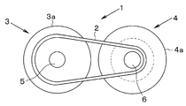
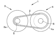
- FIG. 4 schematically shows an example of a belt type continuously variable transmission according to the present invention.
- the belt type continuously variable transmission 1 shown here includes a drive pulley 3 and a driven pulley 4 around which a transmission belt 2 is wound, and each of the pulleys 3 and 4 includes a fixed sheave 3a and 4a and a movable sheave 3b and 4b.
- the surfaces of the fixed sheaves 3a, 4a and the movable sheaves 3b, 4b facing each other are tapered surfaces, and the distance between the facing surfaces changes to a larger or smaller position, so that a position at a predetermined interval, that is, a transmission belt.
- the position that matches the width of 2 changes in the radial direction. In other words, a belt groove is formed by these tapered surfaces.
- the transmission belt 2 is a non-metallic composite belt 2 as an example, and the non-metallic composite belt 2 abuts on these belt grooves when wrapped around the pulleys 3 and 4, and the belt groove A large number of blocks that oppose the pressure received from the groove surface and a resin band for holding the large number of blocks in an annular shape.
- the block is formed by coating a resin or the like on a metal plate-like member such as steel or aluminum alloy.
- a high-strength synthetic resin or the like can be integrally formed on a resin band.
- the left and right side surfaces of the block in the belt width direction are tapered surfaces and come into contact with the belt grooves of the pulleys 3 and 4.
- the driving pulley 3 and the driven pulley 4 are opposite in the relative positions of the fixed sheaves 3a, 4a and the movable sheaves 3b, 4b, but the basic configuration is the same.
- the configuration will be further described.
- the fixed sheaves 3a and 4a are integrated with pulley shafts (that is, rotating shafts) 5 and 6, and the pulley shafts 5 and 6 extend to the tapered surface side of the fixed sheaves 3a and 4a. Yes.
- the movable sheaves 3b and 4b are attached to the pulley shafts 5 and 6 so as to be movable in the axial direction.
- the tapered surface of the movable sheave 3b faces the tapered surface of the fixed sheave 3a of the drive pulley 3, and the driven pulley 4
- the taper surface of the movable sheave 4b is opposed to the taper surface of the fixed sheave 4a.
- thrust is generated on the back side of the movable sheaves 3b, 4b to move the movable sheaves 3b, 4b toward and away from the fixed sheaves 3a, 4a, and the non-metallic composite belt 2 is sandwiched between them.
- the thrust generating device may be, for example, an electric actuator or a hydraulic actuator.
- the thrust generating device may be a thrust for moving the movable sheaves 3b, 4b closer to or away from the fixed sheaves 3a, 4a and the sheaves 3a, 3b, 4a.
- 4b may be configured to generate a clamping pressure for clamping the non-metallic composite belt 2.
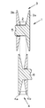
- FIG. 1 schematically shows an example of a tapered surface of a fixed sheave in a driven pulley of a belt type continuously variable transmission according to the present invention.
- the inner portion in the radial direction of the tapered surface of the fixed sheave 4a is configured to have a smaller friction coefficient than the outer portion.
- the inner portion is made of, for example, a synthetic resin material.
- slits are radially formed on the tapered surfaces of the sheaves 4a and 4b from the inner side to the outer side in the radial direction, or roughened stepwise or continuously from the inner part to the outer part.
- the frictional force generated between the nonmetallic composite belt 2 and each tapered surface when the nonmetallic composite belt 2 is sandwiched in the inner portion of each tapered surface is When the non-metallic composite belt 2 is sandwiched, the frictional force generated between the non-metallic composite belt 2 and each tapered surface may be reduced.
- the treatment for roughening the surface may be a plating treatment, etching treatment, blasting, or the like that is generally known in the art.
- the outer portion can start from the state in which the speed ratio of the belt-type continuously variable transmission 1 is the maximum speed ratio, a speed ratio close thereto, or a vehicle in which the belt-type continuously variable transmission 1 is stopped.
- the non-metallic composite belt 2 includes a portion in contact with each tapered surface of the driven pulley 4 when the transmission gear ratio is set. Therefore, the outer portion is configured to ensure a torque capacity to be transmitted at the maximum gear ratio, a gear ratio close thereto or a gear ratio at which the vehicle can start when starting from a state where the vehicle is stopped.
- the outer portion is made of a metal material generally used conventionally.
- the basic configuration of the tapered surface of the fixed sheave 4a of the driven pulley 4 and the tapered surface of the movable sheave 4b is the same.
- FIG. 2 schematically shows a state in which the gear ratio of the belt type continuously variable transmission according to the present invention is reduced.
- the speed ratio of the belt type continuously variable transmission 1 is reduced, in other words, when the vehicle is in an accelerated state, the movable sheave 3b of the drive pulley 3 is fixed to the fixed sheave 3a. Thrust is given so that it may approach.
- the movable sheave 3b approaches the fixed sheave 3a, the width of the belt groove is narrowed, and the non-metallic composite belt 2 is pushed outward in the radial direction, and the winding radius is increased.
- the non-metallic composite belt 2 expands the distance between the fixed sheave 4 a and the movable sheave 4 b, that is, the width of the belt groove. The radius is decreasing.
- each sheave 3 a, 3 b is a non-metallic composite so that the wrapping radius of the non-metallic composite belt 2 does not change due to the clamping pressure sandwiching the non-metallic composite belt 2 in the driven pulley 4.
- the belt 2 is sandwiched.
- the gear ratio of the belt type continuously variable transmission 1 is set in preparation for re-starting after the vehicle stops. Will be increased. That is, it is downshifted. Specifically, in the drive pulley 3, the thrust applied to the movable sheave 3b is reduced or released so that the movable sheave 3b is separated from the fixed sheave 3a. Then, the non-metallic composite belt 2 expands the width of the belt groove in the drive pulley 3, and the non-metallic composite belt 2 moves from the outer portion toward the inner portion in the radial direction of the driving pulley 3, and the winding radius thereof is increased. Decrease.
- the driven pulley 4 a thrust is applied to the movable sheave 4b so as to approach the fixed sheave 4a, and the width of the belt groove is narrowed by the movable sheave 4b approaching the fixed sheave 4a.
- the friction coefficient of the inner portion or the friction force generated in the inner portion in the radial direction of each tapered surface of the driven pulley 4 is made smaller than that of the outer portion. Therefore, as the movable sheave 4b approaches the fixed sheave 4a, the non-metallic composite belt 2 slides and moves from the inner portion to the outer portion in the radial direction of the driven pulley 4, and the winding radius increases. Is done.
- the non-metallic composite belt 2 moves in the radial direction of the driven pulley 4.
- the wrapping radius is increased by sliding from the inner part toward the outer part.
- the movable sheave 4b moves to the fixed sheave 4a side following the movement of the non-metallic composite belt 2 outward in the radial direction of the driven pulley 4.
- FIG. 3 schematically shows a state in which the gear ratio of the belt type continuously variable transmission according to the present invention is increased.
- the gear ratio of the belt type continuously variable transmission 1 is increased as described above, in other words, in the deceleration state of the vehicle on which the belt type continuously variable transmission 1 is mounted, as shown in FIG.
- the metal composite belt 2 comes into contact with the outer portion having a larger friction coefficient and friction force than the inner portion in the radial direction of the driven pulley 4.
- the transmission ratio of the belt-type continuously variable transmission 1 is set to the maximum transmission ratio, a transmission ratio close thereto, or a transmission ratio at which the vehicle can start, the non-metallic composite belt 2 It is a range including the part which contacts.
- each sheave 4a, 4b of the driven pulley 4 sandwiches the non-metallic composite belt 2 with a load corresponding to the torque capacity to be transmitted when the vehicle starts.
- the sheaves 3 a and 3 b sandwich the non-metallic composite belt 2 so that the winding radius of the non-metallic composite belt 2 does not change due to the clamping pressure in the driven pulley 4.
- the vehicle is driven when the vehicle is suddenly decelerated or stopped by sudden braking operation from the traveling state.
- the radially inner portion of the pulley 4 an action that promotes an increase in the winding radius of the non-metallic composite belt 2 occurs, and the speed change speed in the deceleration direction is improved.
- the rotation of the pulleys 3 and 4 is stopped in an accelerated state as shown in FIG.
- the gear ratio of the continuously variable transmission 1 can be set to the maximum gear ratio, a gear ratio close thereto, or a gear ratio at which the vehicle can start. Thereby, the startability of the vehicle can be ensured. Further, since the non-metallic composite belt 2 can be shifted and shifted as described above, the thrust applied to the movable sheave 4b for the shifting can be suppressed or reduced. By suppressing the thrust of the movable sheave 4b, the durability of the non-metallic composite belt 2 and the belt-type continuously variable transmission 1 can be improved.
- each sheave 4a, 4b of the driven pulley 4 since the coefficient of friction of the outer portion in the radial direction of each sheave 4a, 4b of the driven pulley 4 is large, it is possible to secure a torque capacity to be transmitted when the vehicle starts. Further, when the non-metallic composite belt 2 is sandwiched between the friction coefficient of the inner part or the friction force generated when the non-metallic composite belt 2 is sandwiched between the outer parts, the friction coefficient of the inner part or the non-metallic composite belt 2 is sandwiched between the inner part. Since it is larger than the generated frictional force, the thrust applied to the movable sheave 4b can be reduced as compared with the case where torque is transmitted at the inner portion, and the power transmission efficiency can be increased as compared with the inner portion. In other words, the upper limit of the thrust applied to the movable sheave of the driven pulley can be determined.
Landscapes
- Engineering & Computer Science (AREA)
- General Engineering & Computer Science (AREA)
- Mechanical Engineering (AREA)
- Transmissions By Endless Flexible Members (AREA)
- Pulleys (AREA)
Abstract
Description
Claims (5)
- 駆動プーリと従動プーリとのそれぞれが、回転軸に一体化された固定シーブとその固定シーブに対して接近・離隔するように前記回転軸の軸線方向に移動可能な可動シーブとによって構成されるとともに、それらのシーブの対向面が、伝動ベルトを巻き掛けるベルト巻き掛け溝を形成するテーパ面とされ、前記可動シーブを前記回転軸の軸線方向に移動させて前記溝幅を変化させることにより前記伝動ベルトの巻き掛かり半径を変化させて変速比を連続的に変更するベルト式無段変速機において、
前記伝動ベルトは、樹脂によって形成される非金属製ベルトであり、
前記従動プーリの各テーパ面は、それらの半径方向で外側部分の摩擦係数に比較して内側部分の摩擦係数が小さくなるように形成されている
ことを特徴とするベルト式無段変速機。 - 前記外側部分が金属製材料によって形成され、前記内側部分が合成樹脂材料によって形成されている
ことを特徴とする請求項1に記載のベルト式無段変速機。 - 前記従動プーリの前記各テーパ面の半径方向で内側部分から外側部分に向けて放射状のスリットが形成され、もしくはそれらの半径方向で内側部分から外側部分に向けて前記各テーパ面を段階的あるいは連続的に粗面化させる表面処理が施されている
ことを特徴とする請求項1に記載のベルト式無段変速機。 - 前記表面処理は、メッキ処理とエッチング処理とを含む
ことを特徴とする請求項3に記載のベルト式無段変速機。 - 前記非金属製ベルトは、該非金属製ベルトに金属製の小片を取り付けることにより前記非金属製ベルトよりも伝達トルク容量を増大させた非金属製複合ベルトであることを特徴とする請求項1に記載のベルト式無段変速機。
Priority Applications (4)
| Application Number | Priority Date | Filing Date | Title |
|---|---|---|---|
| JP2012555648A JP5505523B2 (ja) | 2011-02-03 | 2011-02-03 | ベルト式無段変速機 |
| CN2011800667058A CN103339412A (zh) | 2011-02-03 | 2011-02-03 | 带式无级变速器 |
| PCT/JP2011/052268 WO2012105024A1 (ja) | 2011-02-03 | 2011-02-03 | ベルト式無段変速機 |
| US13/978,461 US20130303316A1 (en) | 2011-02-03 | 2011-02-03 | Belt-driven continuously variable transmission |
Applications Claiming Priority (1)
| Application Number | Priority Date | Filing Date | Title |
|---|---|---|---|
| PCT/JP2011/052268 WO2012105024A1 (ja) | 2011-02-03 | 2011-02-03 | ベルト式無段変速機 |
Publications (1)
| Publication Number | Publication Date |
|---|---|
| WO2012105024A1 true WO2012105024A1 (ja) | 2012-08-09 |
Family
ID=46602265
Family Applications (1)
| Application Number | Title | Priority Date | Filing Date |
|---|---|---|---|
| PCT/JP2011/052268 Ceased WO2012105024A1 (ja) | 2011-02-03 | 2011-02-03 | ベルト式無段変速機 |
Country Status (4)
| Country | Link |
|---|---|
| US (1) | US20130303316A1 (ja) |
| JP (1) | JP5505523B2 (ja) |
| CN (1) | CN103339412A (ja) |
| WO (1) | WO2012105024A1 (ja) |
Cited By (1)
| Publication number | Priority date | Publication date | Assignee | Title |
|---|---|---|---|---|
| US10591020B2 (en) | 2013-03-28 | 2020-03-17 | Mitsuboshi Belting Ltd. | Transmission belt and belt-speed-change device |
Families Citing this family (6)
| Publication number | Priority date | Publication date | Assignee | Title |
|---|---|---|---|---|
| WO2013049840A1 (en) * | 2011-09-30 | 2013-04-04 | Charles Larsen | Gate roller with tapered side walls, and related methods |
| JP2017036772A (ja) * | 2015-08-07 | 2017-02-16 | 本田技研工業株式会社 | 無段変速機 |
| CN108834682A (zh) * | 2018-07-07 | 2018-11-20 | 周雨馨 | 无级自动变速卷帘机 |
| JP7243641B2 (ja) * | 2020-01-08 | 2023-03-22 | トヨタ自動車株式会社 | 無段変速機 |
| JP7398282B2 (ja) * | 2020-01-09 | 2023-12-14 | 本田技研工業株式会社 | ベルト式無段変速機及びその製造方法 |
| CN114165568A (zh) * | 2021-12-07 | 2022-03-11 | 浙江春风动力股份有限公司 | 无级变速器、车辆及其制动控制方法 |
Citations (6)
| Publication number | Priority date | Publication date | Assignee | Title |
|---|---|---|---|---|
| JPS6061556U (ja) * | 1983-10-05 | 1985-04-30 | トヨタ自動車株式会社 | ベルト駆動式無段変速機 |
| JPH1113845A (ja) * | 1997-06-27 | 1999-01-22 | Nissan Motor Co Ltd | Vベルト式無段変速機構 |
| JP2002256483A (ja) * | 2001-03-02 | 2002-09-11 | Daihatsu Motor Co Ltd | Cvt用プーリーへのめっき方法 |
| WO2004076889A1 (ja) * | 2003-02-28 | 2004-09-10 | Yamaha Hatsudoki Kabushiki Kaisha | ベルト式連続無段変速装置 |
| JP2005273720A (ja) * | 2004-03-23 | 2005-10-06 | Toyota Central Res & Dev Lab Inc | プーリ、ブロック、伝動ベルト、湿式ベルト式無段変速機 |
| JP2006183800A (ja) * | 2004-12-28 | 2006-07-13 | Daihatsu Motor Co Ltd | 乾式複合ベルト |
Family Cites Families (8)
| Publication number | Priority date | Publication date | Assignee | Title |
|---|---|---|---|---|
| US4545779A (en) * | 1983-01-25 | 1985-10-08 | Aisin Warner Kabushiki Kaisha | Power transmission endless belt |
| EP0240912A3 (en) * | 1986-03-31 | 1990-05-30 | Mitsuboshi Belting Ltd. | High load transmission belt |
| CN1240953C (zh) * | 2000-05-09 | 2006-02-08 | 盖茨公司 | 块型连续变速传动(cvt)带 |
| US7070529B2 (en) * | 2001-05-30 | 2006-07-04 | Mitsuboshi Belting Ltd. | Power transmission belt |
| CN100540947C (zh) * | 2003-02-28 | 2009-09-16 | 雅马哈发动机株式会社 | 带式无级变速器,及其带轮、带和装有该变速器的车辆 |
| CN1266400C (zh) * | 2003-11-26 | 2006-07-26 | 程乃士 | 无级变速传动用干式复合型金属带组件 |
| CN201087763Y (zh) * | 2007-09-21 | 2008-07-16 | 王国斌 | 一种机械无级变速器 |
| CN101846165B (zh) * | 2009-03-24 | 2014-07-16 | 三之星机带株式会社 | 带传动装置 |
-
2011
- 2011-02-03 WO PCT/JP2011/052268 patent/WO2012105024A1/ja not_active Ceased
- 2011-02-03 JP JP2012555648A patent/JP5505523B2/ja not_active Expired - Fee Related
- 2011-02-03 US US13/978,461 patent/US20130303316A1/en not_active Abandoned
- 2011-02-03 CN CN2011800667058A patent/CN103339412A/zh active Pending
Patent Citations (6)
| Publication number | Priority date | Publication date | Assignee | Title |
|---|---|---|---|---|
| JPS6061556U (ja) * | 1983-10-05 | 1985-04-30 | トヨタ自動車株式会社 | ベルト駆動式無段変速機 |
| JPH1113845A (ja) * | 1997-06-27 | 1999-01-22 | Nissan Motor Co Ltd | Vベルト式無段変速機構 |
| JP2002256483A (ja) * | 2001-03-02 | 2002-09-11 | Daihatsu Motor Co Ltd | Cvt用プーリーへのめっき方法 |
| WO2004076889A1 (ja) * | 2003-02-28 | 2004-09-10 | Yamaha Hatsudoki Kabushiki Kaisha | ベルト式連続無段変速装置 |
| JP2005273720A (ja) * | 2004-03-23 | 2005-10-06 | Toyota Central Res & Dev Lab Inc | プーリ、ブロック、伝動ベルト、湿式ベルト式無段変速機 |
| JP2006183800A (ja) * | 2004-12-28 | 2006-07-13 | Daihatsu Motor Co Ltd | 乾式複合ベルト |
Cited By (1)
| Publication number | Priority date | Publication date | Assignee | Title |
|---|---|---|---|---|
| US10591020B2 (en) | 2013-03-28 | 2020-03-17 | Mitsuboshi Belting Ltd. | Transmission belt and belt-speed-change device |
Also Published As
| Publication number | Publication date |
|---|---|
| JP5505523B2 (ja) | 2014-05-28 |
| US20130303316A1 (en) | 2013-11-14 |
| CN103339412A (zh) | 2013-10-02 |
| JPWO2012105024A1 (ja) | 2014-07-03 |
Similar Documents
| Publication | Publication Date | Title |
|---|---|---|
| JP5505523B2 (ja) | ベルト式無段変速機 | |
| EP3006777B1 (en) | Belt-type stepless transmission | |
| US20180313439A1 (en) | Hybrid driving apparatus | |
| JP2020063845A (ja) | プーリおよび駆動ベルトを備える無段変速機 | |
| WO2014006744A1 (ja) | 金属ベルト用エレメント | |
| WO2012131999A1 (ja) | ベルト式無段変速機 | |
| JP5945527B2 (ja) | 無段変速機及び無段変速機の制御方法 | |
| WO2012105036A1 (ja) | ベルト式無段変速機 | |
| JP5556730B2 (ja) | ベルト式無段変速機 | |
| JP2018021587A (ja) | 車両用無段変速機 | |
| JP2005331079A (ja) | ベルト式無段変速機およびその制御装置 | |
| JP2014141984A (ja) | 乾式ベルト式無段変速機の推力機構 | |
| JP2012163143A (ja) | ベルト式無段変速機の制御装置 | |
| JP2008208861A (ja) | ベルト式無段変速機 | |
| JP2014098400A (ja) | ベルト式無段変速機のプーリ構造 | |
| CN107642585B (zh) | 带式无级变速器 | |
| JP2011226596A (ja) | ベルト式無段変速機 | |
| JP4848978B2 (ja) | ベルト式無段変速機 | |
| JP2013181655A (ja) | 無段変速機の変速制御装置 | |
| JP2004116536A (ja) | 無段変速機 | |
| JP2017106548A (ja) | 変速機及び支持構造の製造方法 | |
| JP2013177930A (ja) | 乾式のベルト式無段変速機 | |
| JP2025024522A (ja) | 無段変速機用の駆動プーリ及びウェイト部材 | |
| JP2006527829A (ja) | 無段変速機 | |
| JP2009299716A (ja) | 無段変速機 |
Legal Events
| Date | Code | Title | Description |
|---|---|---|---|
| 121 | Ep: the epo has been informed by wipo that ep was designated in this application |
Ref document number: 11857965 Country of ref document: EP Kind code of ref document: A1 |
|
| ENP | Entry into the national phase |
Ref document number: 2012555648 Country of ref document: JP Kind code of ref document: A |
|
| WWE | Wipo information: entry into national phase |
Ref document number: 13978461 Country of ref document: US |
|
| NENP | Non-entry into the national phase |
Ref country code: DE |
|
| 122 | Ep: pct application non-entry in european phase |
Ref document number: 11857965 Country of ref document: EP Kind code of ref document: A1 |