WO2012102325A1 - 液晶表示装置 - Google Patents
液晶表示装置 Download PDFInfo
- Publication number
- WO2012102325A1 WO2012102325A1 PCT/JP2012/051615 JP2012051615W WO2012102325A1 WO 2012102325 A1 WO2012102325 A1 WO 2012102325A1 JP 2012051615 W JP2012051615 W JP 2012051615W WO 2012102325 A1 WO2012102325 A1 WO 2012102325A1
- Authority
- WO
- WIPO (PCT)
- Prior art keywords
- liquid crystal
- film
- layer
- display device
- plate
- Prior art date
- Legal status (The legal status is an assumption and is not a legal conclusion. Google has not performed a legal analysis and makes no representation as to the accuracy of the status listed.)
- Ceased
Links
Images



Classifications
-
- G—PHYSICS
- G02—OPTICS
- G02F—OPTICAL DEVICES OR ARRANGEMENTS FOR THE CONTROL OF LIGHT BY MODIFICATION OF THE OPTICAL PROPERTIES OF THE MEDIA OF THE ELEMENTS INVOLVED THEREIN; NON-LINEAR OPTICS; FREQUENCY-CHANGING OF LIGHT; OPTICAL LOGIC ELEMENTS; OPTICAL ANALOGUE/DIGITAL CONVERTERS
- G02F1/00—Devices or arrangements for the control of the intensity, colour, phase, polarisation or direction of light arriving from an independent light source, e.g. switching, gating or modulating; Non-linear optics
- G02F1/01—Devices or arrangements for the control of the intensity, colour, phase, polarisation or direction of light arriving from an independent light source, e.g. switching, gating or modulating; Non-linear optics for the control of the intensity, phase, polarisation or colour
- G02F1/13—Devices or arrangements for the control of the intensity, colour, phase, polarisation or direction of light arriving from an independent light source, e.g. switching, gating or modulating; Non-linear optics for the control of the intensity, phase, polarisation or colour based on liquid crystals, e.g. single liquid crystal display cells
- G02F1/133—Constructional arrangements; Operation of liquid crystal cells; Circuit arrangements
- G02F1/1333—Constructional arrangements; Manufacturing methods
- G02F1/1335—Structural association of cells with optical devices, e.g. polarisers or reflectors
- G02F1/1336—Illuminating devices
- G02F1/133602—Direct backlight
- G02F1/133606—Direct backlight including a specially adapted diffusing, scattering or light controlling members
Definitions
- the present invention relates to a liquid crystal display device provided with a new brightness enhancement structure.
- the liquid crystal display device is composed of a liquid crystal cell and two polarizing plates sandwiching the liquid crystal cell.
- the light that has passed through the polarizing plate is transmitted and used for display.
- the polarizing plate transmits only light having the same optical axis, the amount of light after transmission is halved. Therefore, in order to reuse the remaining half of the light, a brightness enhancement film is usually used.
- the brightness enhancement film By providing a brightness enhancement film, light having a polarization direction that is absorbed by the polarizer is reflected once by the brightness enhancement film without being incident on the polarizer, and further through a reflective layer or the like provided on the back side thereof. And re-incident on the brightness enhancement film.
- the brightness enhancement film can transmit only the polarized light having a polarization direction that can pass through the polarizer and supply the polarized light to the polarizer.
- light such as a backlight is efficiently displayed on the liquid crystal display. It will be used for image display of the device, and the screen can be brightened.
- the brightness enhancement film transmits linearly polarized light with a predetermined polarization axis and reflects other light, such as a dielectric multilayer thin film or a multilayer laminate of thin film films having different refractive index anisotropy.
- a dielectric multilayer thin film or a multilayer laminate of thin film films having different refractive index anisotropy for example, trade name “DBEF” manufactured by Sumitomo 3M Co., Ltd.
- cholesteric liquid crystal layers particularly oriented films of cholesteric liquid crystal polymers, and those oriented liquid crystal layers supported on a film substrate, Reflecting one of the left and right circularly polarized light and transmitting other light (for example, product name “PCF350” manufactured by Nitto Denko Corporation, product name “Transmax” manufactured by Merck Co., Ltd.), etc.
- PCF350 product name manufactured by Nitto Denko Corporation
- Transmax manufactured by Merck Co., Ltd.
- a brightness enhancement film using a cholesteric liquid crystal layer can be a thin film, it is preferably used for a liquid crystal display device that needs to be thin.
- thinning has been achieved by a technique in which a film substrate for supporting a cholesteric liquid crystal layer is a ⁇ / 4 retardation plate (hereinafter also simply referred to as “ ⁇ / 4 plate”) (Patent Document 2, 3).
- a scattering plate also referred to as a scattering layer, a diffusion plate, or a diffusion sheet
- a scattering plate may be used in the liquid crystal display device for the purpose of effectively operating the brightness enhancement film.
- the luminance improvement as a liquid crystal display device using a ⁇ / 4 retardation plate is designed by a combination of a polarizing plate, a luminance enhancement film, a scattering plate, a material, and positions thereof (Patent Document 3).
- an object of the present invention is to provide a liquid crystal display device with improved brightness.
- a liquid crystal display device having a cholesteric liquid crystal layer, a scattering plate, a ⁇ / 4 retardation plate and a polarizer between a backlight and a liquid crystal cell, A liquid crystal display device, wherein at least one scattering plate is interposed between the ⁇ / 4 retardation plate and the cholesteric liquid crystal layer so as to be in contact with an air layer.
- a liquid crystal display device with improved brightness can be provided.
- the liquid crystal display device includes a backlight (hereinafter simply referred to as “BL”) and a liquid crystal cell (hereinafter also simply referred to as “cell”).
- the liquid crystal display device according to the present invention includes at least a cholesteric liquid crystal layer (hereinafter also simply referred to as “core”), a scattering plate, a ⁇ / 4 retardation plate ( ⁇ / 4 plate), and a cell between BL and a cell.
- core cholesteric liquid crystal layer
- ⁇ / 4 retardation plate ⁇ / 4 plate
- the scattering plate in order to efficiently exhibit the brightness enhancement performance, is between the ⁇ / 4 retardation plate and the cholesteric liquid crystal layer, and the scattering plate is in contact with the air layer. It was completed by finding out that it is necessary to have a structure. Reflection occurs because each film or interlayer has a different refractive index from the beginning, but the utilization efficiency of the reflected light is high in the configuration of the present invention.
- the brightness enhancement structure of the present invention preferably has the following structure. 1.
- BL / colle / scattering plate / air layer / ⁇ / 4 plate / polarizer / cell BL / colle / scattering plate / air layer / scattering plate / ⁇ / 4 plate / polarizer / cell ⁇ cholesteric liquid crystal layer>
- the cholesteric liquid crystal layer refers to a so-called planar molecular arrangement or Grandjean in which the arrangement of constituent molecules has a helical structure and the helical axes of the constituent molecules are aligned substantially perpendicular to the plane direction. It is a layer having a pseudo-layer structure called an array.
- the constituent molecules have a cholesteric structure is not limited to the case where the liquid crystalline material is fixed in the state of a cholesteric liquid crystal phase, for example. Also included are those aligned in a twisted state, such as a cholesteric liquid crystal phase.
- a liquid crystal monomer imparted with polymerizability is cholesterically aligned and then polymerized while maintaining the alignment state, thereby being non-liquid crystalline but having a fixed cholesteric alignment.
- the cholesteric layer may be a liquid crystal layer or a non-liquid crystal layer.
- the material for forming the cholesteric liquid crystal layer conventionally known materials can be used.
- the liquid crystallinity of the liquid crystal material may be either lyotropic or thermotropic, but for example, thermotropic is preferable from the viewpoint of ease of control and the ease of forming a monodomain.
- the liquid crystalline material for example, a material having a large birefringence is preferable because the selective reflection wavelength range can be widened. Further, in order to align the liquid crystalline material at a temperature exhibiting a liquid crystal phase and to fix the alignment under a temperature condition that results in a glass state, the material has a glass transition temperature of 30 to 150 ° C. It is preferably 50 to 130 ° C., particularly preferably 70 to 120 ° C.
- liquid crystal material examples include a liquid crystal polymer, and among them, a cholesteric liquid crystal polymer, a mixture of a nematic liquid crystal polymer and a chiral agent is preferable.
- Such a liquid crystal polymer is not particularly limited and can be appropriately selected.
- a liquid crystal polymer having a main chain of polyester or the like a side chain type liquid crystal polymer having an acrylic main chain, a methacryl main chain, a siloxane main chain, etc .
- Nematic liquid crystal polymer containing a molecular chiral agent, liquid crystal polymer containing a chiral component a mixture thereof.
- Specific examples thereof include, for example, Those disclosed in Japanese Patent No. -239396 can be used.
- liquid crystal material in addition to the liquid crystal polymer, cholesteric low molecular liquid crystal (liquid crystal monomer) can also be used.
- liquid crystal monomer liquid crystal monomer
- a nematic liquid crystal monomer or a polymerizable mesogenic compound can be used together with a chiral agent.
- nematic liquid crystal monomer for example, monomers disclosed in Japanese Patent Application Laid-Open No. 08-239396 can be used.
- the polymerizable mesogenic compound include WO 93/22397, EP 0261712, DE 19504224, DE 4408171, GB 2280445, and specific examples include, for example, trade name LC242 (manufactured by BASF Japan Ltd.), trade name E7 (Merck). And LC-Silicone-CC3767 (manufactured by Wacker-Chem).
- the chiral agent can be synthesized, for example, by the method described in WO98 / 00428. Specific examples include, for example, non-polymerizable chiral compounds such as trade name S101, trade name R811, trade name CB15 (manufactured by Merck), and the like. And a chiral agent such as trade name LC756 (manufactured by BASF Corporation).
- the cholesteric liquid crystal layer can be formed by providing an alignment film on a substrate and coating the material thereon.
- the alignment film is subjected to a corona discharge treatment, if necessary, on the surface of the substrate, and then a solution obtained by dissolving the alignment film material in water or a solvent, reverse gravure coating, direct gravure coating, die coating, It can be formed by applying and drying using a known method such as bar coating and then subjecting the dried coating film to a rubbing treatment.
- cellulose As materials for the alignment film, cellulose, silane coupling agent, polyimide, polyamide, polyvinyl alcohol, epoxy acrylate, silanol oligomer, polyacrylonitrile, phenol resin, polyoxazole, cyclized polyisoprene, etc. can be used. Is particularly preferred.
- modified polyamide examples include those obtained by modifying an aromatic polyamide or an aliphatic polyamide, and those obtained by modifying an aliphatic polyamide are preferable.
- modified to nylon-6, nylon-66, nylon-12, ternary to quaternary copolymer nylon, fatty acid polyamide, or fatty acid block copolymer eg, polyether ester amide, polyester amide
- modification include terminal amino modification, carboxyl modification, hydroxyl modification and the like, and modification in which a part of the amide group is alkylaminated or N-alkoxyalkylated.
- N-alkoxyalkylated modified polyamide examples include N-methoxymethylated part of the amide group of copolymer nylon such as nylon-6, nylon-66, nylon-12 and the like.
- the weight average molecular weight of the modified polyamide is preferably 5,000 to 500,000, more preferably 10,000 to 200,000.
- the thickness of the alignment film is not particularly limited as long as the desired alignment uniformity of the liquid crystal layer can be obtained, and is preferably 0.001 to 5 ⁇ m, and more preferably 0.01 to 2 ⁇ m.
- the base material can be composed of a transparent resin base material.
- the transparent resin substrate is not particularly limited, and a substrate having a thickness of 1 mm and a total light transmittance of 80% or more can be used.
- cycloaliphatic olefin polymer chain olefin polymer such as polyethylene and polypropylene, cellulose ester, polyvinyl alcohol, polyimide, polyarylate, polyester, polycarbonate, polysulfone, polyethersulfone, modified acrylic polymer, epoxy resin, polystyrene And a single layer or laminated film made of a synthetic resin such as an acrylic resin.
- polyethylene terephthalate, alicyclic olefin polymer, or chain olefin polymer is particularly preferable.
- the method for producing the cholesteric liquid crystal composition in the present invention is not particularly limited, and can be produced by mixing each of the above components.
- a cholesteric liquid crystal composition is applied onto an alignment film provided on a substrate to obtain a liquid crystal layer, and then the liquid crystal layer is cured by one or more light irradiations or heating treatments, thereby forming a cholesteric liquid crystal layer. Obtainable.
- Application can be performed by a known method such as an extrusion coating method, a direct gravure coating method, a reverse gravure coating method, a die coating method, or a bar coating method.
- an alignment treatment can be performed as necessary.
- the alignment treatment can be performed, for example, by heating the liquid crystal layer at 50 to 150 ° C. for 0.5 to 10 minutes. By performing the alignment treatment, the cholesteric liquid crystal layer can be aligned well.
- the curing step can be performed by a combination of one or more light irradiations and a heating treatment.
- the heating conditions are, for example, a temperature of 40 to 200 ° C., preferably 50 to 200 ° C., more preferably 50 to 140 ° C., and a time of 1 second to 3 minutes, preferably 5 to 120 seconds. it can.
- light used for light irradiation includes not only visible light but also ultraviolet rays and other electromagnetic waves.
- the light irradiation can be performed, for example, by irradiating light having a wavelength of 200 to 500 nm for 0.01 second to 3 minutes.
- a weakly irradiated ultraviolet ray of 0.01 to 50 mJ / cm 2 and heating may be alternately repeated a plurality of times to obtain a circularly polarized light separating sheet having a wide reflection band.
- a relatively strong ultraviolet ray of 50 to 10,000 mJ / cm 2 is irradiated to completely polymerize the liquid crystalline compound to form a cholesteric liquid crystal layer. it can.
- the expansion of the reflection band and the irradiation with strong ultraviolet rays may be performed in the air, or part or all of the process may be performed in an atmosphere in which the oxygen concentration is controlled (for example, in a nitrogen atmosphere). .
- the step of applying and curing the cholesteric liquid crystal composition on other layers such as an alignment film is not limited to one time, and the coating and curing are repeated a plurality of times to form two or more cholesteric resin layers. You can also.
- a cholesteric liquid crystal layer having a well-oriented rod-like liquid crystalline compound having a ⁇ n of 0.18 or more and a thickness of 5 ⁇ m or more can be easily formed. Can be formed.
- the dry film thickness of the cholesteric liquid crystal layer can be preferably 3.0 ⁇ m to 10.0 ⁇ m, more preferably 3.5 to 8 ⁇ m.
- the dry film thickness refers to the total film thickness of each layer when the cholesteric liquid crystal layer is two or more layers, and the film thickness when the cholesteric liquid crystal layer is one layer.
- the scattering plate is also referred to as a scattering layer, and has a function of uniformly diffusing the light passing therethrough and at the same time canceling the polarization state to the non-polarized state and returning the polarized light to the original natural light state.
- This unpolarized light that is, light in the natural light state is directed to the film interface, repeatedly reflected at the interface, and again passes through the scattering plate and reenters the cholesteric liquid crystal layer and the ⁇ / 4 retardation plate. .
- the liquid crystal display device is characterized in that at least one scattering plate is arranged so as to be in contact with the air layer. Since the refractive index of air is lower than any of optical films used in liquid crystal display devices such as a cholesteric liquid crystal layer, a scattering plate, and a ⁇ / 4 retardation plate, the reflection efficiency as a brightness enhancement structure shall be good. Can do it.
- the scattering plate is preferable to provide the scattering plate on the cholesteric liquid crystal layer or the ⁇ / 4 plate from the viewpoint of increasing the efficiency of the production process.
- a scattering plate which has substantially no backscattering and does not depolarize as described in JP2000-347006A and JP2000-347007A, having a haze of 80% to 90%. % Is preferably used.
- a hologram sheet, a microprism array, a microlens array, etc. have a regular structure inside, they can be used if they do not form interference / moire with the pixel black matrix of the liquid crystal display device.
- the base material of the scattering plate is not particularly limited, and various materials can be used.
- synthetic polymers such as polyethylene, polypropylene, polyvinyl chloride, polyethylene terephthalate, polyethylene naphthalate, polycarbonate, norbornene resin, polyurethane, polyacrylate, polymethyl methacrylate; natural polymers such as cellulose diacetate and cellulose triacetate
- the transparent polymer material can be used.
- These polymer materials can contain additives such as ultraviolet absorbers, antioxidants, and plasticizers as necessary.
- a method for producing a scattering plate using these transparent polymer materials as a base material for example, a method of containing a scattering agent in a base film; a layer containing a scattering agent is provided on one side or both sides of the base film surface A method of roughening one side or both sides of the surface of the base film (providing surface irregularities); and at least two types of photopolymerization capable of differing in the refractive index of the homopolymer obtained by homopolymerization And a method of photocuring a layer formed of a photocurable resin composition containing a monomer or an oligomer. Each of these methods may be used alone, or two or more methods may be used in combination.
- the scattering agent When adopting a method of incorporating a scattering agent in the base film, the scattering agent is kneaded in advance into the transparent polymer material to be the base, and then formed into a film by a casting method or an extrusion method. That's fine.
- a transparent polymer material is formed into a film by a casting method or an extrusion method, and then the scattering agent is added.
- a scattering plate can be produced by applying the dispersed resin liquid on a base film and drying or curing the resin liquid.
- a scattering plate can be manufactured.
- the transparent polymer material is formed into a sheet shape by a casting method or an extrusion method, and then, an embossing roll embossing method or sand blasting.
- the scattering plate can be produced by roughening the surface by the method.
- the scattering agent is not particularly limited as long as it is colorless or white particles, and either organic particles or inorganic particles can be used.
- organic particles include particles made of a polymer compound such as a polyolefin resin such as polystyrene, polyethylene, and polypropylene, and an acrylic resin, and may be a crosslinked polymer.
- a copolymer obtained by copolymerizing two or more monomers selected from ethylene, propylene, styrene, methyl methacrylate, benzoguanamine, formaldehyde, melamine, butadiene and the like can be used.
- the inorganic particles include particles made of silica, silicone, titanium oxide, and the like, and glass beads may be used.
- Examples of the resin liquid used in the method of coating the base film with the resin liquid in which the scattering agent is dispersed include a solvent volatile type or water volatile type resin liquid, and a thermosetting or photocurable resin liquid. Can be used.
- Solvent volatile or water volatile resin liquids include polymers such as polyacrylate, polymethacrylate, polyvinyl chloride, polyvinyl acetate, cellulose, synthetic rubber, alcohols such as methanol, ethanol, propanol, and isopropanol; methyl Cellosolves such as cellosolve and ethyl cellosolve; aromatic solvents such as toluene and xylene; those dissolved or dispersed in organic solvents such as ethyl acetate and methylene chloride; or water can be used.
- polymers such as polyacrylate, polymethacrylate, polyvinyl chloride, polyvinyl acetate, cellulose, synthetic rubber, alcohols such as methanol, ethanol, propanol, and isopropanol; methyl Cellosolves such as cellosolve and ethyl cellosolve; aromatic solvents such as toluene and xylene; those dissolved or dispersed in organic solvent
- thermosetting resin liquid a resin liquid in which a liquid composed of a compound having an epoxy group and a compound condensed with an epoxy group such as an amine can be used.
- Photocurable resin liquids include resin liquids in which known radical photopolymerization initiators are added to compounds having acrylate groups, methacrylate groups, aryl groups, etc., or known photocationic polymerization to compounds having vinyl ether groups or epoxy groups.
- a resin liquid to which an initiator is added can be used.
- additives such as ultraviolet absorbers and antioxidants can be added as necessary.
- the scattering plate is preferably disposed on the cholesteric liquid crystal layer and used as a cholesteric liquid crystal film having a scattering layer in a process.
- the ⁇ / 4 retardation plate obtains almost perfect circularly polarized light in the visible light wavelength range, and therefore, an in-plane letter of approximately 1 ⁇ 4 of the wavelength in the visible light wavelength range. It is a retardation film having a foundation (Ro).
- “Retardation of approximately 1 ⁇ 4 in the wavelength range of visible light” means that the longer the wavelength in the wavelength range of 400 to 700 nm, the larger the retardation, and the in-plane retardation value (Ro450) measured at a wavelength of 450 nm is 80 to 125 nm.
- a range satisfying the relationship in which the retardation value (Ro590) measured at a wavelength of 590 nm is 120 to 160 nm is shown.
- Ro590-Ro450 ⁇ 5 nm It is more preferable that Ro590-Ro450 ⁇ 10 nm.
- ⁇ / 4 retardation plate for example, ⁇ obtained by laminating a plurality of polymer films described in JP-A-5-27118, JP-A-10-68816, and JP-A-10-90521.
- / 4 retardation plate ⁇ obtained by laminating a plurality of polymer films described in JP-A-5-27118, JP-A-10-68816, and JP-A-10-90521.
- / 4 retardation plate ⁇ obtained by stretching one polymer film described in WO 00/65384 pamphlet, WO 00/26705 pamphlet, JP 2000-284126 A, JP 2002-31717 A
- a known ⁇ / 4 retardation plate such as a ⁇ / 4 retardation plate in which at least one optically anisotropic layer is provided on the polymer film described in the publication can be used.
- the direction of the slow axis of the polymer film and the orientation direction of the optically anisotropic layer can be arranged in any direction according to the liquid crystal cell.
- the ⁇ / 4 retardation film is a cellulose ester film subjected to the following oblique stretching treatment.
- the cellulose ester film subjected to the oblique stretching treatment according to the present invention is preferably prepared by stretching the following raw film for oblique stretching.
- the raw film for oblique stretching according to the present invention (hereinafter also simply referred to as “raw film”) is a long oblique stretched film whose molecular orientation direction intersects the width direction of the film.
- the original film contains 0.01 to 1.0% by mass of a solvent, and the thickness of the original film in the width direction is TC.
- T1 and T2 respectively, it is preferable that the following relationship is established between the central portion and the respective end portions.
- the present invention is effective when a raw film is produced by a solution casting method and then obliquely stretched.
- the central portion of the original film refers to the substantial center of the original film, and refers to a range of width length ⁇ ⁇ 0.05 with respect to the true center.
- An edge part means the range from the edge of an original fabric film to width length x0.10.
- the film thickness was measured at 10 points at each position by performing a traverse measurement at a pitch of 5 mm in the width direction using an infrared thickness gauge (manufactured by Kurabo Industries, RX-100). Then, the average value in the range of width length ⁇ ⁇ 1.05 from the true center was defined as the film thickness at the central portion, and the average value in the range of width length ⁇ 1.10 from both ends was defined as the film thickness at the end portion. The average value of the whole width direction was made into the film thickness average value.
- the original film according to the present invention is characterized in that the film thickness at the center is thicker than the film thickness at both ends.
- the amount of residual solvent is substantially larger at the center of the original film produced by the solution casting method than at the end, and the film thickness adjustment by the subsequent oblique stretching process is performed. I think it will be effective.
- the adjustment of the amount of the remaining solvent by the film thickness is more effective as a method of adjusting the portion and the amount of the solvent remaining than changing only the drying conditions in the width direction.
- T1 ⁇ TC and (2) T2 ⁇ TC are preferable, but the following is more preferable.
- the amount of solvent contained in the raw film is defined by the following formula.
- a sample having a width of 100 mm is cut out and measured after being left to stand for 24 hours in an atmosphere of 23 ° C. and 55% RH (mass M1 before heat treatment of the raw film).
- heat treatment is performed in an oven at 115 ° C. for 1 hour, and then cooled in a room at 23 ° C. and 55% RH for 5 hours. Thereafter, the mass before and after the heat treatment for measuring the mass is measured (mass M2 after the heat treatment of the raw film).
- Solvent amount (%) [(M1-M2) / (M2)] ⁇ 100 Adjustment of the film thickness of the center part and the edge part of the raw film according to the present invention can be facilitated by adjusting the lip (dope outlet) when the solution is cast.
- a film is formed by casting a dope onto a cooled belt or drum, so even if a solution called a dope is used, the film thickness at the center and end can be adjusted without leveling. .
- the amount of solvent is sufficient that the central part is thicker than the end part by the thicker film thickness. Therefore, the effect can be exhibited without adjusting the amount of solvent contained per unit raw material volume.
- drying conditions are also given, and the amount of solvent contained per unit volume in the width direction is adjusted so that the amount of solvent at the center portion> the amount of solvent at each end portion.
- cellulose ester film of the present invention As a main component of the cellulose ester film of the present invention, cellulose triacetate, cellulose diacetate, cellulose acetate butyrate, and cellulose acetate propionate are preferable, and among these, cellulose diacetate is preferably used.
- X and Y are the following: A film in which the cellulose ester in the range of the formula is 50% by mass or more of the film constituents is used.
- the cellulose ester film of the present invention preferably contains a sugar ester compound as a physical property improving agent.
- sugar ester compound examples include ester compounds in which at least one pyranose structure or at least one furanose structure is 1 to 12 and all or part of the OH groups in the structure are esterified.
- the proportion of esterification is preferably 40 to 70% or more of the OH groups present in the pyranose structure or furanose structure.
- sugar as a raw material for synthesizing the sugar ester compound examples include the following, but the present invention is not limited to these.
- Glucose galactose, mannose, fructose, xylose or arabinose, lactose, sucrose, nystose, 1F-fructosyl nystose, stachyose, maltitol, lactitol, lactulose, cellobiose, maltose, cellotriose, maltotriose, raffinose or kestose .
- gentiobiose gentiotriose
- gentiotetraose gentiotetraose
- xylotriose galactosyl sucrose
- sucrose for example, sucrose, kestose, nystose, 1F-fructosyl nystose, stachyose and the like are preferable, and sucrose is more preferable.
- the monocarboxylic acid used for esterifying all or part of the OH groups in the pyranose structure or furanose structure is not particularly limited, and known aliphatic monocarboxylic acid, alicyclic monocarboxylic acid, aromatic A group monocarboxylic acid or the like can be used.
- the carboxylic acid used may be one kind or a mixture of two or more kinds.
- the cellulose ester film of the present invention preferably contains an ester compound represented by the general formula (2) as a plasticizer.
- B- (GA) nGB (Wherein B is a hydroxy group or carboxylic acid residue, G is an alkylene glycol residue having 2 to 12 carbon atoms, an aryl glycol residue having 6 to 12 carbon atoms, or an oxyalkylene glycol residue having 4 to 12 carbon atoms)
- A represents an alkylene dicarboxylic acid residue having 4 to 12 carbon atoms or an aryl dicarboxylic acid residue having 6 to 12 carbon atoms, and n represents an integer of 1 or more.
- the alkylene glycol component having 2 to 12 carbon atoms ethylene glycol, propylene glycol, 1,2-butanediol, 1,3-butanediol, 1,2-propanediol, 2-methyl 1 , 3-propanediol, 1,4-butanediol, 1,5-pentanediol, 2,2-dimethyl-1,3-propanediol (neopen
- the compound represented by the general formula (1) or (2) can be appropriately used in the range of 1 to 40% by mass of the cellulose ester film.
- the cellulose acetate film of the present invention can contain a plasticizer other than the compounds represented by the general formulas (1) and (2) as necessary for obtaining the effects of the present invention.
- the plasticizer is not particularly limited, but is preferably a polycarboxylic acid ester plasticizer, a glycolate plasticizer, a phthalate ester plasticizer, a fatty acid ester plasticizer, a polyhydric alcohol ester plasticizer, or an ester plasticizer. Agent, acrylic plasticizer and the like.
- At least one is preferably a polyhydric alcohol ester plasticizer.
- the polyhydric alcohol ester plasticizer is a plasticizer composed of an ester of a divalent or higher aliphatic polyhydric alcohol and a monocarboxylic acid, and preferably has an aromatic ring or a cycloalkyl ring in the molecule.
- a divalent to 20-valent aliphatic polyhydric alcohol ester is preferred.
- the plasticizer can be appropriately used in the range of 1 to 40% by mass of the cellulose ester film.
- the cellulose ester film of the present invention can also contain an ultraviolet absorber.
- the ultraviolet absorber is intended to improve durability by absorbing ultraviolet light having a wavelength of 400 nm or less, and the transmittance at a wavelength of 370 nm is particularly preferably 10% or less, more preferably 5% or less. Preferably it is 2% or less.
- the amount of the UV absorber used is not uniform depending on the type of UV absorber, the operating conditions, etc., but when the dry film thickness of the polarizing plate protective film is 30 to 200 ⁇ m, the amount used is 0.5 to the polarizing plate protective film. Is preferably 10 to 10% by mass, and more preferably 0.6 to 4% by mass.
- Antioxidant are also referred to as deterioration inhibitors.
- a liquid crystal image display device or the like When a liquid crystal image display device or the like is placed in a high humidity and high temperature state, the cellulose acetate film may be deteriorated.
- the antioxidant has a role of delaying or preventing the cellulose acetate film from being decomposed by, for example, the residual solvent amount of halogen in the cellulose acetate film or phosphoric acid of the phosphoric acid plasticizer. It is preferable to make it contain in a film.
- the amount of these compounds added is preferably 1 ppm to 1.0%, more preferably 10 to 1000 ppm in terms of mass ratio with respect to the cellulose derivative.
- the cellulose ester film of the present invention has, for example, silicon dioxide, titanium dioxide, aluminum oxide, zirconium oxide, calcium carbonate, kaolin, talc, calcined calcium silicate, hydrated calcium silicate, aluminum silicate in order to improve handleability. Further, it is preferable to contain inorganic fine particles such as magnesium silicate and calcium phosphate and a matting agent such as a crosslinked polymer. Of these, silicon dioxide is preferable because it can reduce the haze of the film.
- the primary average particle diameter of the fine particles is preferably 20 nm or less, more preferably 5 to 16 nm, and particularly preferably 5 to 12 nm.
- the amount added can be appropriately determined.
- the raw film according to the present invention can be produced by an ordinary solution casting method.
- Production of the raw film according to the present invention by a solution casting method is a step of preparing a dope by dissolving a cellulose ester and an additive in a solvent, a step of casting the dope on an endless metal support that moves infinitely It is performed by a step of drying the cast dope as a web, a step of peeling from the metal support, a step of stretching or maintaining the width, a step of further drying, and a step of winding the finished film.
- the concentration of cellulose ester in the dope is preferably higher because the drying load after casting on the metal support can be reduced. However, if the concentration of cellulose ester is too high, the load during filtration increases and the filtration accuracy is poor. Become.
- the concentration that achieves both of these is preferably 10 to 35% by mass, and more preferably 15 to 25% by mass.
- Solvents used in dope may be used alone or in combination of two or more. It is preferable to use a mixture of a good solvent and a poor solvent of cellulose ester from the viewpoint of production efficiency.
- the good solvent is particularly preferably methylene chloride or methyl acetate.
- Examples of the poor solvent include methanol, ethanol, n- Butanol, cyclohexane, cyclohexanone and the like are preferably used.
- the dope contains 0.01 to 2% by mass of water.
- a general method can be used. When heating and pressurization are combined, it is possible to heat above the boiling point at normal pressure.
- the cellulose ester solution is filtered using an appropriate filter medium such as filter paper.
- a filter medium with an absolute filtration accuracy of 0.008 mm or less is preferable, a filter medium with 0.001 to 0.008 mm is more preferable, and a filter medium with 0.003 to 0.006 mm is more preferable.
- the filter medium is not particularly limited, and a normal filter medium can be used. However, a plastic filter medium such as polypropylene and Teflon (registered trademark) and a metal filter medium such as stainless steel are preferable because they do not drop off fibers. .
- the dope can be filtered by a normal method, but the method of filtering while heating at a temperature not lower than the boiling point of the solvent at normal pressure and in a range where the solvent does not boil under pressure is the filtration pressure before and after filtration.
- the increase in the difference (referred to as differential pressure) is small, and the preferred temperature is 45 to 120 ° C, more preferably 45 to 70 ° C, and even more preferably 45 to 55 ° C.
- the filtration pressure is preferably 1.6 MPa or less, more preferably 1.2 MPa or less, and further preferably 1.0 MPa or less.
- the central portion is adjusted so as to have a predetermined film thickness by adjusting the lip.
- the metal support preferably has a mirror-finished surface, and the cast width can be 1 to 4 m.
- the surface temperature of the metal support in the casting step is ⁇ 50 ° C. to a temperature lower than the boiling point of the solvent, and the preferable support temperature is 0 to 40 ° C., more preferably 5 to 30 ° C.
- the residual solvent amount when peeling the web from the metal support is preferably 10 to 150% by mass, more preferably 20 to 40% by mass or 60 to 130% by mass. Particularly preferred is 20 to 30% by mass or 70 to 120% by mass.
- the web is peeled off from the metal support and further dried to make the residual solvent amount 1% by mass or less.
- a roll drying method (a method in which a plurality of rolls arranged at the top and bottom are alternately passed through the web) or a tenter method is used to dry the web in width.
- ⁇ Slant stretching treatment> The raw film of the present invention is then subjected to an oblique stretching process, and a usual method is adopted.
- a usual method For example, known methods described in JP-A Nos. 2003-215337, 2010-221624, 2010-201659, and International Publication No. 2009/041273 can be used as they are.
- the cellulose ester film according to the present invention has a measurement of detecting the scattered light intensity at a position of 130 ° from the light source when measuring the film scattered light intensity of 90 ° incident light of the scattered light profile of the goniophotometer. It is preferable that the difference in scattered light intensity between the case where the setting direction on the sample stage is aligned with the slow axis and the direction perpendicular thereto is 0.05 or less.
- the scattered light measured by a goniophotometer is preferably within a certain range.
- the scattered light intensity when vertical is preferably in the range of 0.01 to 0.25, more preferably 0.20 or less, and even more preferably 0.10 or less.
- the difference in scattered light intensity is 0.05 or less in the present invention, but the smaller the smaller the better.
- the method described in JP-A-2009-265477 can be used.
- the moisture permeability of the cellulose ester film according to the present invention is preferably 10 to 1200 g / m 2 ⁇ 24 h at 40 ° C. and 90% RH, more preferably 20 to 1000 g / m 2 ⁇ 24 h, and 20 to 850 g / m 2 ⁇ 24 h. Is particularly preferred.
- the moisture permeability can be measured according to the method described in JIS Z 0208.
- the cellulose ester film according to the present invention has a breaking elongation of preferably 10 to 80%, more preferably 20 to 50%.
- the visible light transmittance of the cellulose ester film according to the present invention is preferably 90% or more, and more preferably 93% or more.
- the ⁇ / 4 retardation plate according to the present invention can further be provided with a retardation layer.
- ⁇ Nz> retardation layer where nx ny (C-plate retardation layer)>
- the ⁇ / 4 retardation film thus obtained (a ⁇ / 4 retardation plate provided with a C-plate) preferably has the following characteristics.
- the optically anisotropic layer is preferably an optically anisotropic layer described in JP 2010-250204 A.
- optically anisotropic layer in which rod-like liquid crystal is vertically aligned and fixed in alignment ⁇ Optically anisotropic layer in which rod-like liquid crystal is vertically aligned and fixed in alignment>
- the retardation of the optically anisotropic layer alone according to the present invention is preferably as follows.
- the optically anisotropic layer according to the present invention is obtained by applying a liquid crystal material or a liquid crystal solution on a ⁇ / 4 retardation plate (cellulose ester film) directly or via an intermediate layer, followed by drying and heat treatment (also referred to as alignment treatment). Then, the liquid crystal alignment is fixed by ultraviolet curing or thermal polymerization, and an anisotropic layer made of rod-shaped liquid crystal aligned in the vertical direction is formed.
- rod-like liquid crystal is aligned in the vertical direction
- the phrase “rod-like liquid crystal is aligned in the vertical direction” means that the rod-like liquid crystal is within a range of 70 to 90 ° (vertical direction is 90 °) with respect to the film surface serving as a support.
- the rod-like liquid crystal may be oriented obliquely or the orientation angle may be gradually changed.
- the range is preferably from 80 to 90 °.
- the optically anisotropic layer according to the present invention is preferably a retardation layer made of rod-like liquid crystal oriented in the vertical direction with Ro in the range of 0 to 10 nm and Rt in the range of ⁇ 600 to ⁇ 70 nm. Further, Ro is more preferably in the range of 0 to 5 nm.
- the phase difference of the phase difference of the layer on which the liquid crystal alignment is fixed on these supports can be measured using an AxoScan manufactured by Opto Science Co., Ltd.
- the alignment regulating force extends to the interface opposite to the interface with the air layer, and the alignment film is not particularly necessary, and the configuration can be simplified. This is also preferable from the viewpoint.
- an alignment film composed of a cross-linked product of a block polymer composition containing a (meth) acrylic block polymer described in JP-A-2005-148473 and the like is used.
- Known methods such as a method of using, a method of using a vertical alignment film described in JP 2005-265889 A, and a method of using an air interface vertical alignment agent can be used.
- the orientation of the rod-like liquid crystal layer, the film thickness control, the temperature during UV curing, the tilt angle control, and the pretilt angle at the interface with the support or air layer It is preferable to perform control.
- the liquid crystal layer is formed by curing a liquid crystal material capable of forming a liquid crystal phase at a predetermined temperature with a predetermined liquid crystal regularity.
- the upper limit of the temperature showing the liquid crystal phase is not particularly limited as long as the cellulose ester film of the base material is not damaged.
- the lower limit of the temperature showing the liquid crystal phase can be said to be a temperature at which the liquid crystal material can maintain the alignment state when used as a polarizing plate.
- the liquid crystal material for forming the optically anisotropic layer according to the present invention it is preferable to use a polymerizable liquid crystal material.
- the polymerizable liquid crystal material can be used by being polymerized by irradiating with predetermined actinic radiation. In the polymerized state, the vertical alignment state is fixed.
- any of a polymerizable liquid crystal monomer, a polymerizable liquid crystal oligomer, and a polymerizable liquid crystal polymer can be used, and they can also be mixed with each other.
- the polymerizable liquid crystal monomer described in JP-A-2010-250204 is preferably used because of its high sensitivity in alignment and easy vertical alignment.
- conventionally known materials can be appropriately selected and used as the polymerizable liquid crystal oligomer and the polymerizable liquid crystal polymer.
- the thickness of the optically anisotropic layer according to the present invention is preferably in the range of 0.1 ⁇ m to 10 ⁇ m, and more preferably in the range of 0.2 to 5 ⁇ m.
- a polymerizable liquid crystal material is prepared by using a composition for forming a liquid crystal layer by blending a photopolymerization initiator, a sensitizer, etc., if necessary, and coating on a substrate to form a liquid crystal layer forming layer. To do.
- a method for forming a layer with fixed liquid crystal orientation for example, a dry film or the like is formed in advance and a layer in which liquid crystal orientation is fixed is laminated on a substrate, or a liquid crystal composition is dissolved.
- a liquid crystal composition is added with a solvent and a coating composition in which other components are dissolved is used. It is preferable to form a layer in which the orientation of the liquid crystal is fixed by coating on the substrate and removing the solvent. This is simpler in process than other methods.
- a commonly used polyvinyl alcohol polarizing film can be used as it is as the polarizer.
- iodine is dyed on a polyvinyl alcohol film
- dichroic dye is dyed.
- a polyvinyl alcohol aqueous solution is formed into a film and dyed by uniaxial stretching or dyed or uniaxially stretched and then preferably subjected to a durability treatment with a boron compound.
- the polarizer according to the present invention is preferably used as a polarizing plate by laminating the ⁇ / 4 plate according to the present invention as a polarizing plate protective film.
- the ⁇ / 4 plate according to the present invention is preferably saponified and then bonded using a polyvinyl alcohol-based aqueous adhesive.
- a known polarizing plate protective film can be used on the other surface of the polarizer.
- a commercially available cellulose ester film for example, Konica Minoltack KC8UX, KC4UX, KC5UX, KC8UY, KC4UY, KC12UR, KC8UCR-3, KC8UCR-4, KC8UCR-5, KC8UE, KC4FR-4, KC4FR-3, KC4FR-3, KC4FR-4 -1, KC8UY-HA, KC8UX-RHA, manufactured by Konica Minolta Opto Co., Ltd.) and the like are preferably used.
- Liquid crystal display device By incorporating the structure according to the present invention into a liquid crystal display device, it is possible to produce various liquid crystal display devices with excellent visibility, but particularly for liquid crystal display devices for outdoor use such as large liquid crystal display devices and digital signage. Preferably used.
- the polarizing plate is bonded to the liquid crystal cell via an adhesive layer or the like.
- the mode of the liquid crystal display device is not particularly limited.
- IPS type including FFS system.
- the effect is maintained for a long time without white spots at the periphery of the screen.
- ⁇ Preparation of cholesteric liquid crystal layer> One side of a sheet-like substrate (polyethylene terephthalate film, manufactured by Teijin Chemicals Ltd.) was subjected to corona discharge treatment so that the wetting index was 56 mN / m.
- 3% modified polyamide (FR105 / CM4000 70/30 mass ratio mixture, FR105: methoxymethylated nylon manufactured by Lead City Corporation, CM4000: copolymerized polyamide manufactured by Toray Industries, Inc.) 1
- a propanol solution was applied with a # 4 bar and dried at 120 ° C. for 5 minutes to produce a dry film having a thickness of 0.2 ⁇ m. By rubbing the dry film in one direction, a substrate having an alignment film was obtained.
- the following cholesteric liquid crystal composition was applied to the surface having the alignment film of the transparent resin substrate having the alignment film prepared above with a # 8 bar.
- the coating film was irradiated with 1.0 mJ / cm 2 of ultraviolet rays (UV-A: 365 nm ⁇ 5 nm), held at 100 ° C. for 1 minute, and then irradiated with ultraviolet rays of 500 mJ / cm 2 to cure the coating film.
- UV-A 365 nm ⁇ 5 nm
- a cholesteric liquid crystal film having a scattering layer with a thickness of 20 ⁇ m is subjected to a corona discharge treatment on the surface of the cholesteric liquid crystal layer so as to have a wetting index of 60 mN / m, and a scattering layer composition having the following composition is applied and dried at 100 ° C. for 2 minutes.
- Polyester A has a terminal toluic acid ester because the monocarboxylic acid is used in an amount twice as much as that of the dicarboxylic acid.
- Fine particles (Aerosil R812 manufactured by Nippon Aerosil Co., Ltd.) 11 parts by mass Ethanol 89 parts by mass The above was stirred and mixed with a dissolver for 50 minutes, and then dispersed with Manton Gorin.
- Fine particle addition liquid 1 The fine particle dispersion 1 was slowly added to the dissolution tank containing methylene chloride with sufficient stirring. Further, the particles were dispersed by an attritor so that the secondary particles had a predetermined particle size. This was filtered through Finemet NF manufactured by Nippon Seisen Co., Ltd. to prepare a fine particle additive solution 1.
- a main dope solution having the following composition was prepared. First, methylene chloride and ethanol were added to the pressure dissolution tank. The cellulose ester was added to the pressure dissolution tank containing the solvent while stirring. This is completely dissolved with heating and stirring. This was designated as Azumi Filter Paper No. The main dope solution was prepared by filtration using 244.
- the dope solution was cast on a stainless steel belt support at a temperature of 33 ° C. and a width of 1500 mm so that the central part was thicker than the end part.
- the temperature of the stainless steel belt was controlled at 30 ° C.
- the solvent was evaporated until the amount of residual solvent in the cast (cast) film reached 75%, and then peeled off from the stainless steel belt support with a peeling tension of 110 N / m.
- the peeled cellulose ester film was stretched 5% in the width direction using a tenter while applying heat at 160 ° C.
- the residual solvent at the start of stretching was 15%.
- drying was completed while transporting the drying zone with a number of rolls, and the end sandwiched between tenter clips was slit with a laser cutter, and then wound.
- the drying temperature was 130 ° C. and the transport tension was 100 N / m.
- the raw film was stretched using the offline stretching apparatus 1 shown in FIG.
- the winding portion is passed through the accumulator portion 4, the tenter portion 5, the ear clip device 6, the heat relaxation portion 7, and the cooling portion 8. 9 was conveyed so as to be wound up in a roll shape.
- the accumulator unit 4 a loop was sufficiently created.
- the film was stretched obliquely at a stretching temperature of 175 ° C. and a stretching ratio of 1.5 times.
- the average film thickness of the obtained ⁇ / 4 retardation plate was 50 ⁇ m, and the maximum value and minimum value in the width direction of the film thickness were 50.03 and 49.95, respectively.
- the in-plane retardation value Ro (550) at a wavelength of 550 nm was 140 nm, and the angle ⁇ 1 formed by the in-plane slow axis b and the width direction a was 45 °.
- a ⁇ / 4 retardation film was prepared by providing the following intermediate layer and C-plate retardation layer (optically anisotropic layer) on a ⁇ / 4 retardation plate.
- UV-polymerizable liquid crystal material UCL-018 manufactured by Dainippon Ink & Chemicals, Inc.
- Propylene glycol monomethyl ether 80 parts by mass
- Photopolymerization initiator (Lucirin TPO (manufactured by BASF)
- 0.04 parts by mass hindered amine LS-765 0.02 parts by mass Sensitizer (Kayacure DETX, Nippon Kayaku Co., Ltd.) 0.10 parts by mass
- the following air interface side vertical alignment agent 1 0.01 parts by mass
- the optically anisotropic layer coating solution was applied on the straight alignment film with a thickness of 12 ⁇ m by a die coater. Then, it heated for 2 minutes in a 100 degreeC thermostat, and the rod-shaped liquid crystal compound was orientated.
- the coated film was irradiated with an ultraviolet ray of 250 mJ / mm at an oxygen concentration of 0.2% and a temperature of 28 ° C. for 10 seconds to cure the polymerizable liquid crystal composition to obtain a ⁇ / 4 retardation film.
- the thickness of the optically anisotropic layer was 1.8 ⁇ m.
- the Ro of the optically anisotropic layer was 0 nm and Rt was ⁇ 10 nm.
- the total Ro of the ⁇ / 4 retardation film including the C-plate retardation layer was 140 nm and Rt was ⁇ 60 nm.
- polarizer A 120 ⁇ m-thick long roll polyvinyl alcohol film was immersed in 100 parts by mass of an aqueous solution containing 1 part by mass of iodine and 4 parts by mass of boric acid, and stretched in the transport direction 6 times at 50 ° C. to prepare a polarizer.
- Cellulose ester film VA-TAC 40 ⁇ m similarly saponified on one side of the above polarizer, and ⁇ / 4 retardation film treated with alkali saponification on the opposite side are completely saponified Using a 5% aqueous polyvinyl alcohol solution as an adhesive, the polarizer was bonded to each other so that the transmission axis of the polarizer and the in-plane slow axis of the film were parallel, and dried to prepare a polarizing plate.
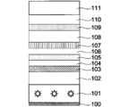
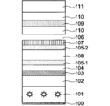
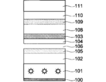
- Each polarizing plate was mounted on a backlight unit for a liquid crystal display device having the configuration shown in FIG. 2 to produce a liquid crystal display device.
- the scattering layer in the comparative film B was prepared by using a 100 ⁇ m polyethylene terephthalate film as a base material, coating the same scattering layer as in the present invention, and arranging the scattering layer side on the comparative film B side.
- the brightness enhancement performance was evaluated using an integrating sphere. Specifically, the measurement light quantity in the state shown in FIG. 6 was set to 100% (blank), and the luminance was measured under the same conditions for the present invention and the comparative luminance enhancement structure. The results are shown in Table 1 below. In addition, the value of luminance% in Table 1 is a relative value when the measurement light quantity in the blank is 100%.
Landscapes
- Physics & Mathematics (AREA)
- Nonlinear Science (AREA)
- Liquid Crystal (AREA)
- Mathematical Physics (AREA)
- Chemical & Material Sciences (AREA)
- Crystallography & Structural Chemistry (AREA)
- General Physics & Mathematics (AREA)
- Optics & Photonics (AREA)
- Polarising Elements (AREA)
Abstract
【課題】輝度向上が改善された液晶表示装置を提供する。 【解決手段】本発明に係る液晶表示装置は、バックライトと、液晶セルとを有するそして、バックライトと液晶セルとの間に、コレステリック液晶層、散乱板、λ/4位相差板および偏光子を有する。そして、λ/4位相差板とコレステリック液晶層との間に、少なくとも1つの散乱板が空気層と接するように介在している点に特徴を有する。
Description
本発明は、新たな輝度向上構造体を備える液晶表示装置に関する。
液晶表示装置は、液晶セルと、その液晶セルを挟む2枚の偏光板とから構成されている。
偏光板を通過した光は透過して表示に使用されるが、偏光板は光軸の揃った光のみを透過することから、透過後の光量は半分となる。そのため、残り半分の光を再利用するため、通常は輝度向上フィルムが使用される。
輝度向上フィルムを設けることにより、偏光子に吸収されるような偏光方向を有する光を偏光子に入射させずに輝度向上フィルムで一旦反射させ、さらにその後ろ側に設けられた反射層等を介して反転させて輝度向上フィルムに再入射させることを繰り返すことができる。これにより、輝度向上フィルムは偏光子を通過しうる偏光方向を有するようになった偏光のみを透過させて偏光子に供給することができ、その結果、バックライトなどの光が効率的に液晶表示装置の画像表示に使用されることとなり、画面を明るくすることができる。
輝度向上フィルムとしては、例えば、誘電体の多層薄膜や、屈折率異方性が相違する薄膜フィルムの多層積層体のような、所定偏光軸の直線偏光を透過して、他の光は反射する特性を示すもの(例えば、住友スリーエム(株)製の商品名「DBEF」等)、コレステリック液晶層、特にコレステリック液晶ポリマーの配向フィルムや、その配向液晶層をフィルム基材上に支持したもので、左右一方の円偏光を反射して、他の光は透過する特性を示すもの(例えば、日東電工(株)製の商品名「PCF350」、Merck(株)製の商品名「Transmax」等)が挙げられる(特許文献1)。
コレステリック液晶層を用いた輝度向上フィルムは、薄膜が可能であることから、薄さが必要な液晶表示装置に好んで使用される。
さらに、コレステリック液晶層を支持するためのフィルム基材をλ/4位相差板(以下、単に「λ/4板」とも称する)とする技術で薄膜化が図られてきている(特許文献2、3)。
一方、輝度向上フィルムを効果的に作用させる目的で、液晶表示装置にはさらに散乱板(散乱層、拡散板、拡散シートともいう)が使用されることもある。
したがって、λ/4位相差板を使用した液晶表示装置としての輝度向上は、偏光板、輝度向上フィルム、散乱板の組み合わせ、素材、およびそれら各々の位置によって設計されている(特許文献3)。
しかしながら、これまでの設計では、実際に設計したものと理論値との乖離があり、目標とする輝度向上を達成することができないことが常であった。
本発明は、上記の課題に鑑み、輝度向上が改善された液晶表示装置を提供することを目的とする。
本発明の上記目的は、以下の構成により達成することができる。
1.バックライトと液晶セルとの間に、コレステリック液晶層、散乱板、λ/4位相差板および偏光子を有する液晶表示装置において、
前記λ/4位相差板と前記コレステリック液晶層との間に、少なくとも1つの前記散乱板が空気層と接するように介在していることを特徴とする、液晶表示装置。
前記λ/4位相差板と前記コレステリック液晶層との間に、少なくとも1つの前記散乱板が空気層と接するように介在していることを特徴とする、液晶表示装置。
2.前記空気層と接する前記散乱板の、前記空気層と接する面とは反対側の面が前記コレステリック液晶層と接するように、前記散乱板が配置されている、上記1に記載の液晶表示装置。
本発明によれば、輝度向上が改善された液晶表示装置を提供することができる。
以下、本発明を実施するための形態について詳細に説明する。
<液晶表示装置>
本発明に係る液晶表示装置は、バックライト(以下、単に「BL」とも称する)と、液晶セル(以下、単に「セル」とも称する)とを有する。また、本発明に係る液晶表示装置は、BLとセルとの間に、少なくともコレステリック液晶層(以下、単に「コレ」とも称する)、散乱板、λ/4位相差板(λ/4板)および偏光子を有する。そして、λ/4位相差板(λ/4板)とコレステリック液晶層との間に、少なくとも1つの前記散乱板が空気層と接するように介在している点に特徴を有する。
本発明に係る液晶表示装置は、バックライト(以下、単に「BL」とも称する)と、液晶セル(以下、単に「セル」とも称する)とを有する。また、本発明に係る液晶表示装置は、BLとセルとの間に、少なくともコレステリック液晶層(以下、単に「コレ」とも称する)、散乱板、λ/4位相差板(λ/4板)および偏光子を有する。そして、λ/4位相差板(λ/4板)とコレステリック液晶層との間に、少なくとも1つの前記散乱板が空気層と接するように介在している点に特徴を有する。
本発明は、輝度向上性能を効率的に発揮させるためには、散乱板がλ/4位相差板とコレステリック液晶層との間にあり、さらに該散乱板は空気層と接触している輝度向上構造体を有することが必要であることを見出したことにより完成されたものである。もともと各フィルムまたは層間では屈折率が相違することから反射が起こるが、その反射光の利用効率が高いのが、本発明の構成である。
本発明の輝度向上構造体としては、以下の構造を有することが好ましい。
1.BL/コレ/散乱板/空気層/λ/4板/偏光子/セル
2.BL/コレ/散乱板/空気層/散乱板/λ/4板/偏光子/セル
<コレステリック液晶層>
本発明に係る液晶表示装置において、コレステリック液晶層とは、構成分子の配列がらせん構造をとり、この構成分子のらせん軸が面方向にほぼ垂直に配向している、いわゆるプレーナ分子配列またはグランジャン配列と呼ばれる擬似層構造を有する層である。
1.BL/コレ/散乱板/空気層/λ/4板/偏光子/セル
2.BL/コレ/散乱板/空気層/散乱板/λ/4板/偏光子/セル
<コレステリック液晶層>
本発明に係る液晶表示装置において、コレステリック液晶層とは、構成分子の配列がらせん構造をとり、この構成分子のらせん軸が面方向にほぼ垂直に配向している、いわゆるプレーナ分子配列またはグランジャン配列と呼ばれる擬似層構造を有する層である。
また、「構成分子がコレステリック構造をとっている」とは、例えば、液晶性材料が、コレステリック液晶相の状態で固定されている場合には限定されず、液晶相ではないが非液晶化合物が前記コレステリック液晶相のようにねじれた状態で配向したものも含む。
例えば、重合性を付与した液晶性モノマーをコレステリック配向させた後、配向状態を維持したまま高分子化することによって、非液晶性であるが、コレステリック配向が固定化されたもの等である。
したがって、前記構成分子がコレステリック配向をとっていれば、前記コレステリック層は、液晶層であっても非液晶層であってもよい。
コレステリック液晶層を形成材料としては、従来公知の材料が使用できる。液晶性材料の液晶性は、リオトロピック性、サーモトロピック性のいずれでもよいが、例えば、制御の簡便性や、モノドメインの形成し易さの点から、サーモトロピック性が好ましい。
液晶性材料としては、例えば、選択反射の波長域を広くできることから、複屈折の大きいものが好ましい。また、前記液晶性材料を、液晶相を示す温度で配向させ、さらに、ガラス状態となる温度条件下で前記配向を固定させるため、前記材料のガラス転移温度は、30~150℃の材料であることが好ましく、より好ましくは50~130℃、特に好ましくは70~120℃である。
液晶性材料としては、例えば、液晶ポリマーがあげられ、中でもコレステリック液晶ポリマー、ネマチック液晶ポリマーとカイラル剤との混合物が好ましい。
このような液晶ポリマーとしては、特に限定されず適宜選択できるが、例えば、ポリエステル等を主鎖とする液晶ポリマー;アクリル主鎖、メタクリル主鎖、シロキサン主鎖等からなる側鎖型液晶ポリマー;低分子カイラル剤を含有するネマチック系液晶ポリマー、カイラル成分を含む液晶ポリマー;ネマチック系液晶ポリマーとコレステリック系液晶ポリマーの混合液晶ポリマー;これらの混合物等があげられ、具体例としては、例えば、特開平08-239496号公報等に開示されているものが使用できる。
また、前記液晶性材料としては、前記液晶ポリマーの他に、コレステリック性の低分子液晶(液晶モノマー)も使用できる。また、ネマチック液晶モノマーまたは重合性メソゲン化合物等を、カイラル剤と共に使用することもできる。
ネマチック液晶モノマーとしては、例えば、特開平08-239496号公報等に開示されているモノマーが使用できる。前記重合性メソゲン化合物としては、例えば、WO93/22397、EP0261712、DE19504224、DE4408171、GB2280445等があげられ、具体例としては、例えば、商品名LC242(BASFジャパン(株)製)、商品名E7(Merck(株)製)、およびLC-Silicone-CC3767(Wacker-Chem(株)製)等がある。
カイラル剤としては、例えばWO98/00428に記載の方法で合成でき、具体例としては、例えば、商品名S101、商品名R811、商品名CB15(Merck(株)製)等の非重合性カイラル化合物や、商品名LC756(BASF(株)製)等のカイラル剤がある。
コレステリック液晶層は、基材の上に配向膜を設け、その上に前記素材を塗布することで形成することができる。
配向膜は、基材表面上に、必要に応じてコロナ放電処理等を施した後、配向膜の材料を水または溶剤に溶解させた溶液等を、リバースグラビアコーティング、ダイレクトグラビアコーティング、ダイコーティング、バーコーティング等の公知の方法を用いて塗布し、乾燥させ、その後乾燥塗膜にラビング処理を施すことにより形成することができる。
配向膜の材料としては、セルロース、シランカップリング剤、ポリイミド、ポリアミド、ポリビニルアルコール、エポキシアクリレート、シラノールオリゴマー、ポリアクリロニトリル、フェノール樹脂、ポリオキサゾール、環化ポリイソプレンなどを用いることができるが、変性ポリアミドが特に好ましい。
変性ポリアミドとしては、芳香族ポリアミドまたは脂肪族ポリアミドに変性を加えたものを挙げることができ、脂肪族ポリアミドに変性を加えたものが好ましい。
具体的には例えば、ナイロン-6、ナイロン-66、ナイロン-12、3元ないし4元共重合ナイロン、脂肪酸系ポリアミド、又は脂肪酸系ブロック共重合体(例えばポリエーテルエステルアミド、ポリエステルアミド)に変性を加えたものを挙げることができる。当該変性としては、末端アミノ変性、カルボキシル変性、ヒドロキシル変性などの変性、並びにアミド基の一部をアルキルアミノ化またはN-アルコキシアルキル化する変性を挙げることができる。
N-アルコキシアルキル化変性ポリアミドとしては、ナイロン-6、ナイロン-66、またはナイロン-12等の共重合ナイロンのアミド基の一部をN-メトキシメチル化したものが挙げられる。
変性ポリアミドの重量平均分子量は、好ましくは5,000~500,000、より好ましくは10,000~200,000である。
配向膜の厚さは、所望する液晶層の配向均一性が得られる膜厚であればよく、0.001~5μmであることが好ましく、0.01~2μmであることがさらに好ましい。
基材は、透明樹脂基材により構成することができる。透明樹脂基材は、特に限定されず1mm厚で全光透過率80%以上の基材を使用することができる。
具体的には、脂環式オレフィンポリマー、ポリエチレンやポリプロピレンなどの鎖状オレフィンポリマー、セルロースエステル、ポリビニルアルコール、ポリイミド、ポリアリレート、ポリエステル、ポリカーボネート、ポリスルホン、ポリエーテルスルホン、変性アクリルポリマー、エポキシ樹脂、ポリスチレン、アクリル樹脂などの合成樹脂からなる単層又は積層のフィルムが挙げられる。
これらの中でも、ポリエチレンテレフタレート、脂環式オレフィンポリマー又は鎖状オレフィンポリマーが特に好ましい。
本発明におけるコレステリック液晶組成物の製造方法は、特に限定されず、上記各成分を混合することにより製造することができる。
コレステリック液晶組成物を、基材上に設けた配向膜上に塗布して液晶層を得、次いで1回以上の、光照射または加温処理によって当該液晶層を硬化することにより、コレステリック液晶層を得ることができる。
塗布は、公知の方法、例えば押し出しコーティング法、ダイレクトグラビアコーティング法、リバースグラビアコーティング法、ダイコーティング法、バーコーティング法等により実施することができる。
前記塗布により得られた液晶層を硬化する前に、必要に応じて、配向処理を施すことができる。配向処理は、例えば液晶層を50~150℃で0.5~10分間加温することにより行うことができる。当該配向処理を施すことにより、コレステリック液晶層を良好に配向させることができる。
硬化の工程は、1回以上の光照射と加温処理との組み合わせにより行うことができる。加温条件は、具体的には例えば、温度40~200℃、好ましくは50~200℃、さらに好ましくは50~140℃、時間は1秒~3分、好ましくは5~120秒とすることができる。
本発明において光照射に用いる光とは、可視光のみならず紫外線およびその他の電磁波をも含む。光照射は、具体的には例えば波長200~500nmの光を0.01秒~3分照射することにより行うことができる。
また、例えば0.01~50mJ/cm2の微弱な紫外線照射と加温とを複数回交互に繰り返し、反射帯域の広い円偏光分離シートとすることもできる。上記の微弱な紫外線照射等による反射帯域の拡張を行った後に、50~10,000mJ/cm2といった比較的強い紫外線を照射し、液晶性化合物を完全に重合させ、コレステリック液晶層とすることができる。
上記の反射帯域の拡張及び強い紫外線の照射は、空気下で行ってもよく、あるいはその工程の一部または全部を、酸素濃度を制御した雰囲気(例えば、窒素雰囲気下)中で行うこともできる。
本発明において、配向膜等の他の層上へのコレステリック液晶組成物の塗布および硬化の工程は、1回に限られず、塗布および硬化を複数回繰り返し2層以上のコレステリック樹脂層を形成することもできる。ただし本発明においては、1回のみのコレステリック液晶組成物の塗布および硬化によっても、良好に配向したΔnが0.18以上の棒状液晶性化合物を含み、かつ5μm以上といった厚みのコレステリック液晶層を容易に形成することができる。
本発明において、コレステリック液晶層の乾燥膜厚は好ましくは3.0μm~10.0μm、より好ましくは3.5~8μmとすることができる。なお、前記乾燥膜厚は、コレステリック液晶層が2以上の層である場合は、各層の膜厚の合計を、コレステリック液晶層が1層である場合にはその膜厚をさす。
<散乱板>
本発明に係る液晶表示装置において、散乱板は、散乱層とも称され、通過する光を均一に散乱すると同時に偏光状態を解消して非偏光状態とし、偏光を元の自然光状態に戻す作用を有する。この非偏光状態、すなわち自然光状態の光がフィルム界面に向かい、その界面で反射を繰り返し、再び散乱板を通過してコレステリック液晶層、λ/4位相差板に再入射することを繰り返すことになる。
本発明に係る液晶表示装置において、散乱板は、散乱層とも称され、通過する光を均一に散乱すると同時に偏光状態を解消して非偏光状態とし、偏光を元の自然光状態に戻す作用を有する。この非偏光状態、すなわち自然光状態の光がフィルム界面に向かい、その界面で反射を繰り返し、再び散乱板を通過してコレステリック液晶層、λ/4位相差板に再入射することを繰り返すことになる。
そして、本発明に係る液晶表示装置においては少なくとも1つの散乱板が空気層と接するように配置されている点に特徴がある。空気の屈折率はコレステリック液晶層、散乱板、λ/4位相差板等の液晶表示装置に使用される光学フィルムのいずれよりも低いことから、輝度向上構造体として反射効率がよいものとすることができるのである。
散乱板のみを独立して設けることも可能であるが、コレステリック液晶層上や、λ/4板上に設けることが、生産工程の効率化の観点からは好ましい。
本発明においては実質的に後方散乱を有さない、偏光を解消しない、特開2000-347006号公報、特開2000-347007号公報に記載されているような散乱板で、ヘイズ80%~90%の物が好適に用いられる。
その他、ホログラムシート、マイクロプリズムアレイ、マイクロレンズアレイ等、内部に規則性構造を有していても液晶表示装置の画素ブラックマトリクスと干渉/モアレを形成しなければ使用可能である。
具体的には、散乱板の基材は特に限定されず、各種材料を用いることができる。たとえば、ポリエチレン、ポリプロピレン、ポリ塩化ビニル、ポリエチレンテレフタレート、ポリエチレンナフタレート、ポリカーボネート、ノルボルネン系樹脂、ポリウレタン、ポリアクリレート、ポリメチルメタクリレート等の合成高分子;二酢酸セルロース、三酢酸セルロース等の天然高分子などの透明高分子材料が使用できる。またこれらの高分子材料は、必要に応じて、紫外線吸収剤や酸化防止剤、可塑剤等の添加剤を含有することができる。
これらの透明高分子材料を基材として散乱板を製造する方法としては、たとえば、基材フィルム中に散乱剤を含有させる方法;基材フィルム表面の片側または両側に散乱剤を含有する層を付与する方法;基材フィルム表面の片側または両側を粗面化する(表面凹凸を付与する)方法;および、単独重合して得られる単独重合体の屈折率に差がある少なくとも2種類の光重合可能なモノマーまたはオリゴマーを含有する光硬化性樹脂組成物からなる層を光硬化させる方法などを挙げることができる。これらの方法は、それぞれ単独で使用してもよいし、あるいは2種以上の方法を組み合わせて使用してもよい。
基材フィルム中に散乱剤を含有させる方法を採用する場合には、基材となる透明高分子材料中にあらかじめ散乱剤を混練しておき、それをキャスト法または押出し法によりフィルム状に成形すればよい。
また基材フィルム表面の片側または両側に散乱剤を含有する層を付与する方法を採用する場合には、まず透明高分子材料をキャスト法または押出し法によりフィルム状に成形し、次いで、散乱剤が分散された樹脂液を基材フィルム上に塗工し、該樹脂液を乾燥または硬化させることにより、散乱板を製造することができる。
あるいは、基材フィルムとなる透明高分子材料と、あらかじめ散乱剤を混練した透明高分子材料とを用いた共押出法により、基材フィルム上に散乱剤を含有する層が積層された多層構造からなる散乱板を製造することもできる。
また、基材フィルムの表面を粗面化する方法を採用する場合には、まず、透明高分子材料をキャスト法または押出し法によりシート状に成形し、次いで、エンボス加工ロールによる型押し法やサンドブラスト法により表面を粗面化して散乱板を製造することができる。
上記散乱剤としては、無色または白色の粒子であれば特に限定されず、有機粒子、無機粒子のいずれも使用できる。有機粒子としては、たとえば、ポリスチレン、ポリエチレン、ポリプロピレンのようなポリオレフィン系樹脂、アクリル系樹脂等の高分子化合物からなる粒子が挙げられ、架橋された高分子であってもよい。
また、エチレン、プロピレン、スチレン、メタクリル酸メチル、ベンゾグアナミン、ホルムアルデヒド、メラミン、ブタジエン等から選ばれる2種以上のモノマーが共重合されてなる共重合体を使用することもできる。無機粒子としては、たとえば、シリカ、シリコーン、酸化チタン等からなる粒子が挙げられ、またガラスビーズであってもよい。
上記散乱剤が分散された樹脂液を基材フィルム上に塗工する方法において用いられる樹脂液としては、溶剤揮発型または水揮発型の樹脂液や、熱硬化型または光硬化型の樹脂液が使用できる。
溶剤揮発型または水揮発型の樹脂液としては、ポリアクリレート、ポリメタクリレート、ポリ塩化ビニル、ポリ酢酸ビニル、セルロース、合成ゴムなどの高分子を、メタノール、エタノール、プロパノール、イソプロパノール等のアルコール類;メチルセロソルブ、エチルセロソルブ等のセロソルブ類;トルエン、キシレン等の芳香族系溶剤;酢酸エチル、塩化メチレン;などの有機溶剤もしくは水に、溶解または分散させたものが使用できる。
これらの溶剤揮発型または水揮発型の樹脂液を基材フィルム上に塗工した場合には、乾燥により有機溶剤または水を揮発させて被膜を形成させる。
熱硬化型の樹脂液としては、エポキシ基を有する化合物からなる液と、アミンをはじめとするエポキシ基と縮合する化合物とを混合した樹脂液などが使用できる。
光硬化型の樹脂液としては、アクリレート基やメタクリレート基、アリール基などを有する化合物に公知の光ラジカル重合開始剤を添加した樹脂液や、ビニルエーテル基やエポキシ基を有する化合物に公知の光カチオン重合開始剤を添加した樹脂液が使用できる。
これらの樹脂液には、必要に応じて、紫外線吸収剤や酸化防止剤等の添加剤を添加することができる。
散乱板は、コレステリック液晶層の上に配置され、散乱層を有するコレステリック液晶フィルムとして使用することが工程的に好ましい。
<λ/4位相差板(λ/4板)>
本発明に係る液晶表示装置において、λ/4位相差板は、可視光の波長の範囲においてほぼ完全な円偏光を得るため、可視光の波長の範囲において概ね波長の1/4の面内レターデーション(Ro)を有する位相差フィルムである。
本発明に係る液晶表示装置において、λ/4位相差板は、可視光の波長の範囲においてほぼ完全な円偏光を得るため、可視光の波長の範囲において概ね波長の1/4の面内レターデーション(Ro)を有する位相差フィルムである。
「可視光の波長の範囲において概ね1/4のレターデーション」とは、波長400~700nmにおいて長波長ほどレターデーションが大きく、波長450nmで測定した面内レターデーション値(Ro450)が80~125nmであり、かつ波長590nmで測定したレターデーション値(Ro590)が120~160nmである関係を満足する範囲を示す。
Ro590-Ro450≧5nmであることがさらに好ましく、Ro590-Ro450≧10nmであることが特に好ましい。
本発明に係るλ/4位相差板としては、例えば、特開平5-27118号公報、特開平10-68816号公報、特開平10-90521号公報に記載された複数のポリマーフィルムを積層したλ/4位相差板、WO00/65384号パンフレット、WO00/26705号パンフレットに記載された1枚のポリマーフィルムを延伸したλ/4位相差板、特開2000-284126号公報、特開2002-31717号公報に記載されたポリマーフィルム上に少なくとも1層以上の光学異方性層を設けたλ/4位相差板など公知のλ/4位相差板を用いることができる。
また、ポリマーフィルムの遅相軸の方向や光学異方性層の配向方向は液晶セルに合わせて任意の方向に配置することができる。
本発明においては、λ/4位相差板が下記の斜め延伸処理したセルロースエステルフィルムであることが最も好ましい。
<斜め延伸処理したセルロースエステルフィルム>
本発明に係る斜め延伸処理したセルロースエステルフィルムは、下記の斜め延伸用原反フィルムを延伸処理して作製することが好ましい。
本発明に係る斜め延伸処理したセルロースエステルフィルムは、下記の斜め延伸用原反フィルムを延伸処理して作製することが好ましい。
本発明に係る斜め延伸用原反フィルム(以下、単に「原反フィルム」とも称する)は、分子の配向方向が当該フィルムの幅手方向に対して交差する方向である長尺状の斜め延伸フィルムを製造する前の斜め延伸用原反フィルムであって、該原反フィルムが0.01~1.0質量%の溶媒を含有し、かつ該原反フィルム幅手方向中央部の膜厚をTC、該原反フィルム幅手方向両端部の膜厚をそれぞれT1およびT2としたとき、該中央部と該それぞれの端部の間に、下記関係を有することを特徴とすることが好ましい。
(1)T1<TC
(2)T2<TC。
(1)T1<TC
(2)T2<TC。
本発明は、原反フィルムを溶液流延法で作製し、その後斜め延伸処理する場合に有効である。
〈原反フィルムの膜厚〉
本発明に原反フィルムにおいて中央部とは、原反フィルムの実質的な中央をいい、真の中央に対して幅長×±0.05の範囲をいう。端部とは、原反フィルムの端から幅長×0.10までの範囲をいう。
本発明に原反フィルムにおいて中央部とは、原反フィルムの実質的な中央をいい、真の中央に対して幅長×±0.05の範囲をいう。端部とは、原反フィルムの端から幅長×0.10までの範囲をいう。
膜厚は、赤外線式厚み計(クラボウ社製、RX-100)を用いて、幅方向5mmピッチのトラバース測定を行い各位置10点測定した。そして、真の中央から幅長×±1.05の範囲の平均値を中央部の膜厚とし、両端から幅長×1.10の範囲の平均値を端部の膜厚とした。幅手方向全体の平均値を膜厚平均値とした。
本発明に係る原反フィルムでは、中央部の膜厚が、両端部の膜厚よりも厚いことを特徴とする。かような構成とすることにより、溶液流延法によって作製された原反フィルムの中央部には、端部よりも残存溶媒量が実質的に多くなり、その後の斜め延伸処理による膜厚調整が効果的に行われるようになると考えている。膜厚による残存溶媒量の調整は、溶媒を残す部分、量を調整する方法として、乾燥条件のみを幅手方向で変化させることよりも有効である。
本発明に係る原反フィルムでは、上述したように(1)T1<TCおよび(2)T2<TCであることが好ましいが、下記であることがより好ましい。
(3)T1×1.005<TC<T1×1.05
(4)T2×1.005<TC<T2×1.05。
(3)T1×1.005<TC<T1×1.05
(4)T2×1.005<TC<T2×1.05。
なお、原反フィルムに含まれる溶媒の量は、下記式で定義される。
具体的には、幅長×100mmの試料を切り出し、23℃55%RH雰囲気下で24時間放置した後の質量を測定する(原反フィルムの加熱処理前質量M1)。ついで、115℃で1時間の加熱処理をオーブンで行い、23℃55%RHの部屋にて5時間冷却する。その後質量を測定する加熱処理前後の質量を測定する(原反フィルムの加熱処理後質量M2)。
溶媒量(%)=[(M1-M2)/(M2)]×100
本発明に係る原反フィルムの中央部、端部の膜厚の調整は、溶液流延する際のリップ(ドープの排出口)を調整することで容易にすることができる。溶液流延法では冷却したベルトまたはドラムにドープを流延することで製膜するため、ドープという溶液を使用してもレベリングすることなく、中央部、端部の膜厚を調整することができる。
本発明に係る原反フィルムの中央部、端部の膜厚の調整は、溶液流延する際のリップ(ドープの排出口)を調整することで容易にすることができる。溶液流延法では冷却したベルトまたはドラムにドープを流延することで製膜するため、ドープという溶液を使用してもレベリングすることなく、中央部、端部の膜厚を調整することができる。
溶媒量は、中央部が膜厚の厚い分だけ端部よりも多いことで足りる。したがって、単位原反体積当たりに含まれる溶媒量まで調整しなくとも効果を発揮することができる。好ましくは、乾燥条件も付与し、幅手方向の単位体積当たりに含まれる溶媒量を、中央部溶媒量>それぞれの端部溶媒量、に調整することである。
〈原反フィルムの材料〉
(セルロースエステル〉
本発明のセルロースエステルフィルムの主成分としては、セルローストリアセテート、セルロースジアセテート、セルロースアセテートブチレート、セルロースアセテートプロピオネートが好ましく、中でもセルロースジアセテートが好ましく用いられる。
(セルロースエステル〉
本発明のセルロースエステルフィルムの主成分としては、セルローストリアセテート、セルロースジアセテート、セルロースアセテートブチレート、セルロースアセテートプロピオネートが好ましく、中でもセルロースジアセテートが好ましく用いられる。
本発明のセルロースエステルフィルムは、特に偏光板保護フィルムに求められる光学等方性の観点から、アセチル基の置換度をX、その他のアシル基の置換度をYとした時、X、Yが下記式の範囲にあるセルロースエステルをフィルム構成成分の50質量%以上であるフィルムが用いられる。
式 2.0≦X+Y≦3.0
置換されていない部分は水酸基として存在している。
置換されていない部分は水酸基として存在している。
(添加剤)
本発明のセルロースエステルフィルムには、物性改良剤として糖エステル化合物を含有させることが好ましい。
本発明のセルロースエステルフィルムには、物性改良剤として糖エステル化合物を含有させることが好ましい。
糖エステル化合物としては、例えば、ピラノース構造又はフラノース構造の少なくとも一種を1個以上12個以下有しその構造のOH基のすべてもしくは一部をエステル化したエステル化合物が挙げられる。
エステル化の割合としては、ピラノース構造又はフラノース構造内に存在するOH基の40~70%以上であることが好ましい。
前記糖エステル化合物の合成原料の糖の例としては、例えば以下のようなものを挙げることができるが、本発明はこれらに限定されるものではない。
グルコース、ガラクトース、マンノース、フルクトース、キシロース、あるいはアラビノース、ラクトース、スクロース、ニストース、1F-フラクトシルニストース、スタキオース、マルチトール、ラクチトール、ラクチュロース、セロビオース、マルトース、セロトリオース、マルトトリオース、ラフィノースあるいはケストース挙げられる。
この他、ゲンチオビオース、ゲンチオトリオース、ゲンチオテトラオース、キシロトリオース、ガラクトシルスクロースなども挙げられる。
これらの化合物の中で、特にピラノース構造とフラノース構造を両方有する化合物が好ましい。
例としてはスクロース、ケストース、ニストース、1F-フラクトシルニストース、スタキオースなどが好ましく、更に好ましくは、スクロースである。
前記ピラノース構造又はフラノース構造中のOH基のすべてもしくは一部をエステル化するのに用いられるモノカルボン酸としては、特に制限はなく、公知の脂肪族モノカルボン酸、脂環族モノカルボン酸、芳香族モノカルボン酸等を用いることができる。用いられるカルボン酸は一種類でもよいし、二種以上の混合であってもよい。
本発明のセルロースエステルフィルムには、一般式(2)で表されるエステル化合物を可塑剤として含有することが好ましい。
一般式(2) B-(G-A)n-G-B
(式中、Bはヒドロキシ基またはカルボン酸残基、Gは炭素数2~12のアルキレングリコール残基または炭素数6~12のアリールグリコール残基または炭素数が4~12のオキシアルキレングリコール残基、Aは炭素数4~12のアルキレンジカルボン酸残基または炭素数6~12のアリールジカルボン酸残基を表す。nは1以上の整数を表す。)
一般式(2)において、炭素数2~12のアルキレングリコール成分としては、エチレングリコール、プロピレングリコール、1,2-ブタンジオール、1,3-ブタンジオール、1,2-プロパンジオール、2-メチル1,3-プロパンジオール、1,4-ブタンジオール、1,5-ペンタンジオール、2,2-ジメチル-1,3-プロパンジオール(ネオペンチルグリコール)、2,2-ジエチル-1,3-プロパンジオール(3,3-ジメチロールペンタン)、2-n-ブチル-2-エチル-1,3プロパンジオール(3,3-ジメチロールヘプタン)、3-メチル-1,5-ペンタンジオール1,6-ヘキサンジオール、2,2,4-トリメチル1,3-ペンタンジオール、2-エチル1,3-ヘキサンジオール、2-メチル1,8-オクタンジオール、1,9-ノナンジオール、1,10-デカンジオール、1,12-オクタデカンジオール等があり、これらのグリコールは、1種または2種以上の混合物として使用される。
(式中、Bはヒドロキシ基またはカルボン酸残基、Gは炭素数2~12のアルキレングリコール残基または炭素数6~12のアリールグリコール残基または炭素数が4~12のオキシアルキレングリコール残基、Aは炭素数4~12のアルキレンジカルボン酸残基または炭素数6~12のアリールジカルボン酸残基を表す。nは1以上の整数を表す。)
一般式(2)において、炭素数2~12のアルキレングリコール成分としては、エチレングリコール、プロピレングリコール、1,2-ブタンジオール、1,3-ブタンジオール、1,2-プロパンジオール、2-メチル1,3-プロパンジオール、1,4-ブタンジオール、1,5-ペンタンジオール、2,2-ジメチル-1,3-プロパンジオール(ネオペンチルグリコール)、2,2-ジエチル-1,3-プロパンジオール(3,3-ジメチロールペンタン)、2-n-ブチル-2-エチル-1,3プロパンジオール(3,3-ジメチロールヘプタン)、3-メチル-1,5-ペンタンジオール1,6-ヘキサンジオール、2,2,4-トリメチル1,3-ペンタンジオール、2-エチル1,3-ヘキサンジオール、2-メチル1,8-オクタンジオール、1,9-ノナンジオール、1,10-デカンジオール、1,12-オクタデカンジオール等があり、これらのグリコールは、1種または2種以上の混合物として使用される。
一般式(1)または(2)で表される化合物は、セルロースエステルフィルムの1~40質量%の範囲で適宜使用することができる。
(その他の可塑剤)
本発明のセルロースアセテートフィルムは、本発明の効果を得る上で必要に応じて一般式(1)、(2)で表される化合物以外の可塑剤を含有することができる。
本発明のセルロースアセテートフィルムは、本発明の効果を得る上で必要に応じて一般式(1)、(2)で表される化合物以外の可塑剤を含有することができる。
可塑剤は特に限定されないが、好ましくは、多価カルボン酸エステル系可塑剤、グリコレート系可塑剤、フタル酸エステル系可塑剤、脂肪酸エステル系可塑剤および多価アルコールエステル系可塑剤、エステル系可塑剤、アクリル系可塑剤等から選択される。
そのうち、可塑剤を2種以上用いる場合は、少なくとも1種は多価アルコールエステル系可塑剤であることが好ましい。
多価アルコールエステル系可塑剤は2価以上の脂肪族多価アルコールとモノカルボン酸のエステルよりなる可塑剤であり、分子内に芳香環またはシクロアルキル環を有することが好ましい。好ましくは2~20価の脂肪族多価アルコールエステルである。
本発明のセルロースエステルフィルムにおいて可塑剤は、セルロースエステルフィルムの1~40質量%の範囲で適宜使用することができる。
(紫外線吸収剤)
本発明のセルロースエステルフィルムは、紫外線吸収剤を含有することもできる。紫外線吸収剤は400nm以下の紫外線を吸収することで、耐久性を向上させることを目的としており、特に波長370nmでの透過率が10%以下であることが好ましく、より好ましくは5%以下、更に好ましくは2%以下である。
本発明のセルロースエステルフィルムは、紫外線吸収剤を含有することもできる。紫外線吸収剤は400nm以下の紫外線を吸収することで、耐久性を向上させることを目的としており、特に波長370nmでの透過率が10%以下であることが好ましく、より好ましくは5%以下、更に好ましくは2%以下である。
紫外線吸収剤の使用量は、紫外線吸収剤の種類、使用条件等により一様ではないが、偏光板保護フィルムの乾燥膜厚が30~200μmの場合は、偏光板保護フィルムに対して0.5~10質量%が好ましく、0.6~4質量%が更に好ましい。
(酸化防止剤)
酸化防止剤は劣化防止剤ともいわれる。高湿高温の状態に液晶画像表示装置などがおかれた場合には、セルロースアセテートフィルムの劣化が起こる場合がある。
酸化防止剤は劣化防止剤ともいわれる。高湿高温の状態に液晶画像表示装置などがおかれた場合には、セルロースアセテートフィルムの劣化が起こる場合がある。
酸化防止剤は、例えば、セルロースアセテートフィルム中の残留溶媒量のハロゲンやリン酸系可塑剤のリン酸等によりセルロースアセテートフィルムが分解するのを遅らせたり、防いだりする役割を有するので、前記セルロースアセテートフィルム中に含有させるのが好ましい。
これらの化合物の添加量は、セルロース誘導体に対して質量割合で1ppm~1.0%が好ましく、10~1000ppmが更に好ましい。
(微粒子)
本発明のセルロースエステルフィルムには、取扱性を向上させる為、例えば二酸化ケイ素、二酸化チタン、酸化アルミニウム、酸化ジルコニウム、炭酸カルシウム、カオリン、タルク、焼成ケイ酸カルシウム、水和ケイ酸カルシウム、ケイ酸アルミニウム、ケイ酸マグネシウム、リン酸カルシウム等の無機微粒子や架橋高分子などのマット剤を含有させることが好ましい。中でも二酸化ケイ素がフィルムのヘイズを小さくできるので好ましい。
本発明のセルロースエステルフィルムには、取扱性を向上させる為、例えば二酸化ケイ素、二酸化チタン、酸化アルミニウム、酸化ジルコニウム、炭酸カルシウム、カオリン、タルク、焼成ケイ酸カルシウム、水和ケイ酸カルシウム、ケイ酸アルミニウム、ケイ酸マグネシウム、リン酸カルシウム等の無機微粒子や架橋高分子などのマット剤を含有させることが好ましい。中でも二酸化ケイ素がフィルムのヘイズを小さくできるので好ましい。
微粒子の1次平均粒子径としては、20nm以下が好ましく、更に好ましくは、5~16nmであり、特に好ましくは、5~12nmである。添加量は、適宜さだめることができる。
〈原反フィルムの作製法〉
本発明に係る原反フィルムは通常の溶液流延法で製造することができる。
本発明に係る原反フィルムは通常の溶液流延法で製造することができる。
本発明に係る原反フィルムの溶液流延法による製造は、セルロースエステル及び添加剤を溶剤に溶解させてドープを調製する工程、ドープを無限に移行する無端の金属支持体上に流延する工程、流延したドープをウェブとして乾燥する工程、金属支持体から剥離する工程、延伸または幅保持する工程、さらに乾燥する工程、仕上がったフィルムを巻取る工程により行われる。
ドープを調製する工程について述べる。ドープ中のセルロースエステルの濃度は、濃い方が金属支持体に流延した後の乾燥負荷が低減できて好ましいが、セルロースエステルの濃度が濃過ぎると濾過時の負荷が増えて、濾過精度が悪くなる。これらを両立する濃度としては、10~35質量%が好ましく、さらに好ましくは、15~25質量%である。
ドープで用いられる溶剤は、単独で用いても2種以上を併用してもよい。セルロースエステルの良溶剤と貧溶剤を混合して使用することが生産効率の点で好ましく、良溶剤として特に好ましくはメチレンクロライドまたは酢酸メチルが挙げられ、貧溶剤として、例えば、メタノール、エタノール、n-ブタノール、シクロヘキサン、シクロヘキサノン等が好ましく用いられる。
また、ドープ中には水が0.01~2質量%含有していることが好ましい。また、セルロースエステルの溶解に用いられる溶媒は、フィルム製膜工程で乾燥によりフィルムから除去された溶媒を回収し、これを再利用して用いられる。
上記記載のドープを調製する時の、セルロースエステルの溶解方法としては、一般的な方法を用いることができる。加熱と加圧を組み合わせると常圧における沸点以上に加熱できる。
次に、このセルロースエステル溶液を濾紙等の適当な濾過材を用いて濾過する。濾過材としては、絶対濾過精度0.008mm以下の濾材が好ましく、0.001~0.008mmの濾材がより好ましく、0.003~0.006mmの濾材がさらに好ましい。
濾材さらには特に制限はなく、通常の濾材を使用することができるが、ポリプロピレン、テフロン(登録商標)等のプラスチック製の濾材や、ステンレススティール等の金属製の濾材が繊維の脱落等がなく好ましい。
ドープの濾過は通常の方法で行うことができるが、溶剤の常圧での沸点以上で、且つ加圧下で溶剤が沸騰しない範囲の温度で加熱しながら濾過する方法が、濾過前後の濾圧の差(差圧という)の上昇が小さく、好ましい温度は45~120℃であり、45~70℃がより好ましく、45~55℃であることがさらに好ましい。
濾圧は小さい方が好ましい。濾圧は1.6MPa以下であることが好ましく、1.2MPa以下であることがより好ましく、1.0MPa以下であることがさらに好ましい。
ついで、ドープの流延について説明する。
ドープをステンレスベルトまたはドラム等の金属支持体に流延(キャスト)する。この際、中央部はリップを調整し所定の膜厚をなるように調整する。
金属支持体は、表面を鏡面仕上げしたものが好ましく、キャストの幅は1~4mとすることができる。
流延工程の金属支持体の表面温度は-50℃~溶剤の沸点未満の温度で、好ましい支持体温度は0~40℃であり、5~30℃がさらに好ましい。
原反フィルムが良好な平面性を示すためには、金属支持体からウェブを剥離する際の残留溶媒量は10~150質量%が好ましく、さらに好ましくは20~40質量%または60~130質量%であり、特に好ましくは、20~30質量%または70~120質量%である。
また、原反フィルムの乾燥工程においては、ウェブを金属支持体より剥離し、さらに乾燥し、残留溶媒量を1質量%以下とする。
フィルム乾燥工程では一般にロール乾燥方式(上下に配置した多数のロールをウェブを交互に通し乾燥させる方式)やテンター方式でウェブを幅保持したなら乾燥する方式が採られる。
このように乾燥後巻き取りを、して本発明の原反フィルムが作製される。
〈斜め延伸処理〉
本発明の原反フィルムは、その後斜め延伸処理されるが、その方法は通常の方法が採用される。例えば、特開2003-215337号公報、同2010-221624号公報、同2010-201659号公報、国際公開2009/041273号明細書記載の公知の方法をそのまま使用することができる。
本発明の原反フィルムは、その後斜め延伸処理されるが、その方法は通常の方法が採用される。例えば、特開2003-215337号公報、同2010-221624号公報、同2010-201659号公報、国際公開2009/041273号明細書記載の公知の方法をそのまま使用することができる。
〈セルロースエステルフィルムの物性〉
本発明に係るセルロースエステルフィルムは、ゴニオフォトメーターの散乱光プロファイルの入射光90°のフィルム散乱光強度を測定した時に、光源から130°の位置における散乱光強度を検出する測定において、該フィルムの試料台への設置方向を遅相軸に合わせた場合とその直交方向にした場合の散乱光強度の差が0.05以下であることが好ましい。
本発明に係るセルロースエステルフィルムは、ゴニオフォトメーターの散乱光プロファイルの入射光90°のフィルム散乱光強度を測定した時に、光源から130°の位置における散乱光強度を検出する測定において、該フィルムの試料台への設置方向を遅相軸に合わせた場合とその直交方向にした場合の散乱光強度の差が0.05以下であることが好ましい。
(ゴニオフォトメーターにより測定される散乱光)
本発明に係るセルロースエステルフィルムは、本発明の面内リターデーションの範囲を得るために延伸処理をしても、ゴニオフォトメーターによって測定された散乱光が、一定の範囲にあることが好ましい。
本発明に係るセルロースエステルフィルムは、本発明の面内リターデーションの範囲を得るために延伸処理をしても、ゴニオフォトメーターによって測定された散乱光が、一定の範囲にあることが好ましい。
この異方性散乱は、ゴニオフォトメーターにより測定される。水平にした場合、垂直にした場合の散乱光強度は0.01~0.25の範囲であることが好ましく、0.20以下がより好ましく、0.10以下がさらに好ましい。
散乱光強度の差は、本発明では0.05以下であるが、小さければ小さい方がよい。ゴニオフォトメーターによる測定は、特開2009-265477号公報に記載の方法を使用することができる。
(その他の物性)
本発明に係るセルロースエステルフィルムの透湿度は、40℃、90%RHで10~1200g/m2・24hが好ましく、更に20~1000g/m2・24hが好ましく、20~850g/m2・24hが特に好ましい。透湿度はJIS Z 0208に記載の方法に従い測定することができる。
本発明に係るセルロースエステルフィルムの透湿度は、40℃、90%RHで10~1200g/m2・24hが好ましく、更に20~1000g/m2・24hが好ましく、20~850g/m2・24hが特に好ましい。透湿度はJIS Z 0208に記載の方法に従い測定することができる。
本発明に係るセルロースエステルフィルムは、破断伸度は10~80%であることが好ましく20~50%であることが更に好ましい。
本発明に係るセルロースエステルフィルムの可視光透過率は、90%以上であることが好ましく、93%以上であることが更に好ましい。
本発明に係るλ/4位相差板には、さらに位相差層を設けることができる。この位相差層は、ポジティブCプレート(nz>nx=nyである位相差フィルム)であることが好ましい。
<nz>nx=nyである位相差層(C-プレート位相差層)>
本発明に係るλ/4位相差板に設けられうる「nz>nx=nyである位相差層(C-プレート位相差層、光学異方性層ともいう)」は、本発明に係るλ/4位相差板に、棒状の液晶を垂直に配向させ固定させて得られる層である。そして、このようにして得られるλ/4位相差フィルム(λ/4位相差板にC-プレートが設けられてなるもの)は、下記の特性を有することが好ましい。
<nz>nx=nyである位相差層(C-プレート位相差層)>
本発明に係るλ/4位相差板に設けられうる「nz>nx=nyである位相差層(C-プレート位相差層、光学異方性層ともいう)」は、本発明に係るλ/4位相差板に、棒状の液晶を垂直に配向させ固定させて得られる層である。そして、このようにして得られるλ/4位相差フィルム(λ/4位相差板にC-プレートが設けられてなるもの)は、下記の特性を有することが好ましい。
25nm≦Ro≦150nm
-300nm≦Rt≦40nm
この特性は、λ/4位相差板、棒状の液晶を垂直に配向させて配向を固定した光学異方性層および場合によってはその他の中間層のRo、Rtの総和となる。なお、光学異方性層は、特開2010-250204号公報の光学異方性層であることが好ましい。
-300nm≦Rt≦40nm
この特性は、λ/4位相差板、棒状の液晶を垂直に配向させて配向を固定した光学異方性層および場合によってはその他の中間層のRo、Rtの総和となる。なお、光学異方性層は、特開2010-250204号公報の光学異方性層であることが好ましい。
<棒状の液晶を垂直に配向させて配向を固定した光学異方性層>
本発明に係る光学異方性層単独でのリターデーションは、下記の通りであることが好ましい。
本発明に係る光学異方性層単独でのリターデーションは、下記の通りであることが好ましい。
0≦Ro≦10nm
-600nm≦Rt≦-70nm
本発明に係る光学異方性層は、液晶材料または液晶の溶液をλ/4位相差板(セルロースエステルフィルム)上に直接または中間層を介して塗布し、乾燥と熱処理(配向処理ともいう)を行い紫外線硬化または熱重合などで液晶配向の固定化を行い、垂直方向に配向した棒状液晶による異方性層が形成されてなるものである。
-600nm≦Rt≦-70nm
本発明に係る光学異方性層は、液晶材料または液晶の溶液をλ/4位相差板(セルロースエステルフィルム)上に直接または中間層を介して塗布し、乾燥と熱処理(配向処理ともいう)を行い紫外線硬化または熱重合などで液晶配向の固定化を行い、垂直方向に配向した棒状液晶による異方性層が形成されてなるものである。
ここで、棒状液晶が「垂直方向に配向する」とは、棒状液晶が支持体となるフィルム面に対して70~90°(垂直方向を90°とする)の範囲内にあることをいう。
棒状液晶は、斜め配向しても、配向角を徐々に変化していてもよい。好ましくは80~90°の範囲である。
上述したように、本発明に係る光学異方性層はRoが0~10nm、Rtが-600~-70nmの範囲にある垂直方向に配向した棒状液晶による位相差層であることが好ましい。さらに、Roは0~5nmの範囲がより好ましい。これらの支持体上の液晶配向を固定化した層の位相差の位相差測定は、株式会社オプトサイエンス社製AxoScanを用いて測定することができる。
棒状液晶を配向させて光学異方性層を形成する際には、いわゆる液晶材料が垂直方向に配列するような垂直配向剤を塗布した配向膜を用い、液晶材料を垂直配向したのち固定する方法をとることができる。
液晶材料自身が空気層との界面で垂直方向に配向する場合には、その配向規制力が空気層との界面と反対の界面までおよび、該配向膜は特に必要ではなく、構成が簡素化できる観点からもその方が好ましい。
液晶材料を垂直に配向する具体的な方法としては、特開2005-148473号公報などに記載されている(メタ)アクリル系ブロックポリマーを含有するブロックポリマー組成物の架橋体からなる配向膜等を用いる方法、同2005-265889号公報に記載されている垂直配向膜を使用する方法、空気界面垂直配向剤を使用する方法等公知の方法を使用することができる。
光学異方性層のリターデーションを上記範囲とするためには、棒状液晶層の配向、膜厚制御、紫外線硬化時の温度、チルト角制御、および支持体や空気層との界面でのプレチルト角の制御を行うことが好ましい。
前記液晶層は、所定の温度で液晶相となり得る液晶材料が、所定の液晶規則性を有して硬化することにより形成されたものである。液晶相を示す温度の上限は、例えば基材のセルロースエステルフィルムがダメージを受けない温度であれば特に限定されるものはない。
具体的には、プロセス温度のコントロールの容易性と寸法精度維持の観点から120℃以下が好ましく、より好ましくは100℃以下の温度で液晶相となる液晶材料が好適に用いられる。一方、液晶相を示す温度の下限は、偏光板として用いる際に、液晶材料が配向状態を保持しうる温度であるといえる。
本発明に係る光学異方性層を形成する液晶材料としては、重合性液晶材料を用いることが好ましい。重合性液晶材料は、所定の活性放射線を照射することにより重合させて用いることができ、重合させた状態では垂直の配向状態は固定化される。
重合性液晶材料としては、重合性液晶モノマー、重合性液晶オリゴマー、または重合性液晶ポリマーのいずれかを用いることができ、相互に混合して用いることもできる。
重合性液晶材料としては、上記のうちでも、配向に際しての感度が高く垂直に配向させることが容易であることから特開2010-250204号公報記載の重合性液晶モノマーが好適に用いられる。
以上のほか、本発明においては、重合性液晶オリゴマーや重合性液晶ポリマーとして、従来提案されている公知の材料を適宜選択して用いることが可能である。
本発明に係る光学異方性層の膜厚は0.1μm~10μmの範囲内であることが好ましく、0.2~5μmの範囲内であることがより好ましい。
重合性液晶材料は、必要に応じて光重合開始剤、増感剤等を配合して液晶層形成用組成物を調製して用い、基材上に塗工し、液晶層形成用層を形成する。
液晶の配向を固定した層を形成する方法としては、例えばドライフィルム等をあらかじめ形成してこれを液晶の配向を固定した層としたものを基材上に積層する方法や、液晶組成物を溶解あるいは融解させて基材上に塗工する方法等をとることも可能であるが、本発明においては、液晶組成物としては溶媒を加えて、その他の成分を溶解した塗工用組成物を用いて基材上に塗工し、溶媒を除去することにより液晶の配向を固定した層を形成することが好ましい。これは、他の方法と比較して工程上簡便である。
<偏光子>
本発明に係る液晶表示装置において、偏光子は、通常使用されているポリビニルアルコール系偏光フィルムをそのまま使用することができる。これはポリビニルアルコール系フィルムにヨウ素を染色させたものと二色性染料を染色させたものがある。
本発明に係る液晶表示装置において、偏光子は、通常使用されているポリビニルアルコール系偏光フィルムをそのまま使用することができる。これはポリビニルアルコール系フィルムにヨウ素を染色させたものと二色性染料を染色させたものがある。
偏光子は、ポリビニルアルコール水溶液を製膜し、これを一軸延伸させて染色するか、染色した後一軸延伸してから、好ましくはホウ素化合物で耐久性処理を行ったものが用いられる。
<偏光板>
本発明に係る偏光子は、本発明に係るλ/4板を偏光板保護フィルムとして貼合して偏光板として使用することが好ましい。この際、本発明に係るλ/4板を鹸化処理した後、ポリビニルアルコール系の水性接着剤を使用して貼合することが好ましい。
本発明に係る偏光子は、本発明に係るλ/4板を偏光板保護フィルムとして貼合して偏光板として使用することが好ましい。この際、本発明に係るλ/4板を鹸化処理した後、ポリビニルアルコール系の水性接着剤を使用して貼合することが好ましい。
偏光子のもう一方の面には公知の偏光板保護フィルムを用いることができる。例えば、市販のセルロースエステルフィルム(例えば、コニカミノルタタック KC8UX、KC4UX、KC5UX、KC8UY、KC4UY、KC12UR、KC8UCR-3、KC8UCR-4、KC8UCR-5、KC8UE、KC4UE、KC4FR-3、KC4FR-4、KC4HR-1、KC8UY-HA、KC8UX-RHA、以上コニカミノルタオプト(株)製)等が好ましく用いられる。
<液晶表示装置>
本発明に係る構造を液晶表示装置に組み込むことによって、種々の視認性に優れた液晶表示装置を作製することができるが、特に大型の液晶表示装置やデジタルサイネージ等の屋外用途の液晶表示装置に好ましく用いられる。なお、偏光板は、粘着層等を介して液晶セルに貼合される。
本発明に係る構造を液晶表示装置に組み込むことによって、種々の視認性に優れた液晶表示装置を作製することができるが、特に大型の液晶表示装置やデジタルサイネージ等の屋外用途の液晶表示装置に好ましく用いられる。なお、偏光板は、粘着層等を介して液晶セルに貼合される。
本発明に係る液晶表示装置のモードは特に制限されないが、たとえば、反射型、透過型、半透過型LCDまたはTN型、STN型、OCB型、HAN型、VA型(PVA型、MVA型)、IPS型(FFS方式も含む)等の各種駆動方式のLCDで好ましく用いられる。特にVA型の画面が30型以上、特に30型~54型の大画面の表示装置では、画面周辺部での白抜け等もなく、その効果が長期間維持される。
以下に実施例を挙げて本発明を具体的に説明するが、本発明はこれらに限定されるものではない。
<コレステリック液晶層の作製>
シート状基材(ポリエチレンテレフタレートフィルム、帝人化成(株)製)の片面に、濡れ指数が56mN/mになるようにコロナ放電処理を施した。
シート状基材(ポリエチレンテレフタレートフィルム、帝人化成(株)製)の片面に、濡れ指数が56mN/mになるようにコロナ放電処理を施した。
このコロナ放電処理面に、3%の変性ポリアミド(FR105/CM4000の70/30質量比の混合物、FR105:鉛市(株)製メトキシメチル化ナイロン、CM4000:東レ(株)製共重合ポリアミド)1-プロパノール溶液を#4バーにて塗布し、120℃で5分間乾燥し、膜厚0.2μmの乾膜を作製した。該乾膜を一方向にラビング処理することで、配向膜を有する基材を得た。
下記コレステリック液晶組成物を、上記で調製した配向膜を有する透明樹脂基材の配向膜を有する面に#8バーにて塗布した。
(コレステリック液晶組成物)
液晶化合物(メルク(株)BL-008 ne=1.807 no=1.527)94.93質量部
光重合開始剤イルガキュア907(BASFジャパン(株)製)3.1質量部
界面活性剤(セイミケミカル(株)製KH-40)0.11質量部
カイラル剤(BASF(株)製LC756)5.07質量部
メチルエチルケトン(溶媒)154.82質量部
塗膜を100℃で5分間配向処理し、当該塗膜に対して1.0mJ/cm2の紫外線(UV-A:365nm±5nm)を照射し、100℃で1分間保持し、次いで紫外線を500mJ/cm2照射して塗膜を硬化させて、膜厚4μmのコレステリック液晶層を形成した。
液晶化合物(メルク(株)BL-008 ne=1.807 no=1.527)94.93質量部
光重合開始剤イルガキュア907(BASFジャパン(株)製)3.1質量部
界面活性剤(セイミケミカル(株)製KH-40)0.11質量部
カイラル剤(BASF(株)製LC756)5.07質量部
メチルエチルケトン(溶媒)154.82質量部
塗膜を100℃で5分間配向処理し、当該塗膜に対して1.0mJ/cm2の紫外線(UV-A:365nm±5nm)を照射し、100℃で1分間保持し、次いで紫外線を500mJ/cm2照射して塗膜を硬化させて、膜厚4μmのコレステリック液晶層を形成した。
<散乱層の作製>
コレステリック液晶層表面に、濡れ指数60mN/mになるようにコロナ放電処理を施し、下記の組成の散乱層組成物を塗布、100℃2分乾燥させ、膜厚20μmの散乱層を有するコレステリック液晶フィルムを得た。
コレステリック液晶層表面に、濡れ指数60mN/mになるようにコロナ放電処理を施し、下記の組成の散乱層組成物を塗布、100℃2分乾燥させ、膜厚20μmの散乱層を有するコレステリック液晶フィルムを得た。
メタクリル酸メチル-アクリル酸メチル共重合体(Mw=100000 97:3モル比)100質量部
エポキシ架橋剤E-AX(綜研化学(株)製)1.1質量部
架橋アクリル粒子ケミスノーMX300(平均粒径3.0μm 綜研化学(株)製)4.3質量部
酢酸エチル 300質量部
2-ブタノン 100質量部
<λ/4位相差板の作製>
〈斜め延伸セルロースエステルフィルムの作製〉
(ポリエステルAの作製)
窒素雰囲気下、テレフタル酸ジメチル4.85g、1,2-プロピレングリコール4.4g、p-トルイル酸6.8g、テトライソプロピルチタネート10mgを混合し、140℃で2時間攪拌を行った後、更に210℃で16時間攪拌を行った。次に、170℃まで降温し、未反応物の1,2-プロピレングリコールを減圧留去することにより、ポリエステルAを得た。
エポキシ架橋剤E-AX(綜研化学(株)製)1.1質量部
架橋アクリル粒子ケミスノーMX300(平均粒径3.0μm 綜研化学(株)製)4.3質量部
酢酸エチル 300質量部
2-ブタノン 100質量部
<λ/4位相差板の作製>
〈斜め延伸セルロースエステルフィルムの作製〉
(ポリエステルAの作製)
窒素雰囲気下、テレフタル酸ジメチル4.85g、1,2-プロピレングリコール4.4g、p-トルイル酸6.8g、テトライソプロピルチタネート10mgを混合し、140℃で2時間攪拌を行った後、更に210℃で16時間攪拌を行った。次に、170℃まで降温し、未反応物の1,2-プロピレングリコールを減圧留去することにより、ポリエステルAを得た。
酸価 :0.1
数平均分子量:490
分散度 :1.4
分子量300~1800の成分含有率:90%
ヒドロキシル(水酸基)価:0.1
ヒドロキシル基(水酸基)含有量:0.04%
ポリエステルAはジカルボン酸に対してモノカルボン酸が2倍モル使用されているので末端がトルイル酸エステルになっている。
数平均分子量:490
分散度 :1.4
分子量300~1800の成分含有率:90%
ヒドロキシル(水酸基)価:0.1
ヒドロキシル基(水酸基)含有量:0.04%
ポリエステルAはジカルボン酸に対してモノカルボン酸が2倍モル使用されているので末端がトルイル酸エステルになっている。
〈微粒子分散液1〉
微粒子(アエロジル R812 日本アエロジル(株)製)11質量部
エタノール 89質量部
以上をディゾルバーで50分間攪拌混合した後、マントンゴーリンで分散を行った。
微粒子(アエロジル R812 日本アエロジル(株)製)11質量部
エタノール 89質量部
以上をディゾルバーで50分間攪拌混合した後、マントンゴーリンで分散を行った。
〈微粒子添加液1〉
メチレンクロライドを入れた溶解タンクに十分攪拌しながら、微粒子分散液1をゆっくりと添加した。さらに、二次粒子の粒径が所定の大きさとなるようにアトライターにて分散を行った。これを日本精線(株)製のファインメットNFで濾過し、微粒子添加液1を調製した。
メチレンクロライドを入れた溶解タンクに十分攪拌しながら、微粒子分散液1をゆっくりと添加した。さらに、二次粒子の粒径が所定の大きさとなるようにアトライターにて分散を行った。これを日本精線(株)製のファインメットNFで濾過し、微粒子添加液1を調製した。
メチレンクロライド 99質量部
微粒子分散液1 5質量部
下記組成の主ドープ液を調製した。まず加圧溶解タンクにメチレンクロライドとエタノールを添加した。溶剤の入った加圧溶解タンクにセルロースエステルを攪拌しながら投入した。これを加熱し、攪拌しながら、完全に溶解し。これを安積濾紙(株)製の安積濾紙No.244を使用して濾過し、主ドープ液を調製した。
微粒子分散液1 5質量部
下記組成の主ドープ液を調製した。まず加圧溶解タンクにメチレンクロライドとエタノールを添加した。溶剤の入った加圧溶解タンクにセルロースエステルを攪拌しながら投入した。これを加熱し、攪拌しながら、完全に溶解し。これを安積濾紙(株)製の安積濾紙No.244を使用して濾過し、主ドープ液を調製した。
〈主ドープ液の組成〉
メチレンクロライド 340質量部
エタノール 64質量部
セルロースジアセテート(アセチル基置換度2.4)100質量部
下記糖エステル化合物A 7.0質量部
ポリエステルA 2.5質量部
TINUVIN928(BASFジャパン社製) 1.5質量部
微粒子添加液1 1質量部
メチレンクロライド 340質量部
エタノール 64質量部
セルロースジアセテート(アセチル基置換度2.4)100質量部
下記糖エステル化合物A 7.0質量部
ポリエステルA 2.5質量部
TINUVIN928(BASFジャパン社製) 1.5質量部
微粒子添加液1 1質量部

以上を密閉容器に投入し、攪拌しながら溶解してドープ液を調製した。
次いで、無端ベルト流延装置を用い、ドープ液を温度33℃、1500mm幅でステンレスベルト支持体上に、中央部が端部より厚くなるようにリップを調整し流延した。ステンレスベルトの温度は30℃に制御した。
ステンレスベルト支持体上で、流延(キャスト)したフィルム中の残留溶媒量が75%になるまで溶媒を蒸発させ、次いで剥離張力110N/mで、ステンレスベルト支持体上から剥離した。
剥離したセルロースエステルフィルムを、160℃の熱をかけながらテンターを用いて幅方向に5%延伸した。延伸開始時の残留溶媒は15%であった。
次いで、乾燥ゾーンを多数のロールで搬送させながら乾燥を終了させ、テンタークリップで挟んだ端部をレーザーカッターでスリットし、その後巻き取った。乾燥温度は130℃で、搬送張力は100N/mとした。
以上のようにして、平均乾燥膜厚75μm、中央部の膜厚TC76.0μm、端部T1およびT2ともに74.5μmのロール状の原反フィルムを得た。
この原反フィルムを図1に記載のオフライン延伸装置1を用いて延伸した。
まず、原反フィルムをフィルム送出装置13のロール取付軸10に取りつけ、送出位置にセットした後、アキューム部4、テンター部5、耳切装置6、熱緩和部7、冷却部8を経て巻取部9でロール状に巻き取られるように搬送した。アキューム部4では十分にループを作成するようにした。テンター部では、延伸温度175℃、延伸倍率1.5倍で斜め延伸した。
得られたλ/4位相差板の平均膜厚は50μm、膜厚の幅手方向の最大値、最小値は、それぞれ50.03、49.95であった。波長550nmでの面内位相差値Ro(550)は140nm、面内遅相軸bと幅手方向aとのなす角度θ1は45°であった。
〈C-プレート位相差層の作製〉
λ/4位相差板に、下記中間層およびC-プレート位相差層(光学異方性層)を設けλ/4位相差フィルムを作製した。
λ/4位相差板に、下記中間層およびC-プレート位相差層(光学異方性層)を設けλ/4位相差フィルムを作製した。
(中間層塗布液)
ウレタンアクリレートオリゴマー(UV-7510B 日本合成化学(株))25質量部
プロピレングリコールモノメチルエーテル 290質量部
イソプロピルアルコール 685質量部
セルロースエステル(アセチル基置換度1.66、プロピオニル基置換度0.82、 総アシル基置換度2.48 Mw=80000)0.025質量部
光重合開始剤(ルシリンTPO BASF(株)製)0.05質量部
この塗布液を、λ/4位相差板にワイヤーバー#3で塗布し80℃で30秒乾燥後、紫外線を120mJ/mmを10秒照射して硬化した。乾燥後の中間層の膜厚は、0.5μmであった。
ウレタンアクリレートオリゴマー(UV-7510B 日本合成化学(株))25質量部
プロピレングリコールモノメチルエーテル 290質量部
イソプロピルアルコール 685質量部
セルロースエステル(アセチル基置換度1.66、プロピオニル基置換度0.82、 総アシル基置換度2.48 Mw=80000)0.025質量部
光重合開始剤(ルシリンTPO BASF(株)製)0.05質量部
この塗布液を、λ/4位相差板にワイヤーバー#3で塗布し80℃で30秒乾燥後、紫外線を120mJ/mmを10秒照射して硬化した。乾燥後の中間層の膜厚は、0.5μmであった。
〈光学異方性層(垂直配向液晶)塗布液〉
紫外線重合性液晶材料(UCL-018 大日本インキ化学工業(株)製)20質量部
プロピレングリコールモノメチルエーテル 80質量部
光重合開始剤(ルシリンTPO(BASF(株)製))0.04質量部
ヒンダードアミンLS-765(三共ライフテック株式会社製)0.02質量部
増感剤(カヤキュアーDETX、日本化薬(株)製)0.10質量部
下記空気界面側垂直配向剤1 0.01質量部
紫外線重合性液晶材料(UCL-018 大日本インキ化学工業(株)製)20質量部
プロピレングリコールモノメチルエーテル 80質量部
光重合開始剤(ルシリンTPO(BASF(株)製))0.04質量部
ヒンダードアミンLS-765(三共ライフテック株式会社製)0.02質量部
増感剤(カヤキュアーDETX、日本化薬(株)製)0.10質量部
下記空気界面側垂直配向剤1 0.01質量部

この光学異方性層塗布液をダイコータにより前記素直配向膜上にウェット12μmの厚みで塗布した。その後100℃の恒温槽中で2分間加熱し、棒状液晶化合物を配向させた。
次にコートしたフィルムに酸素濃度0.2%、温度28℃にて250mJ/mmの紫外線を10秒照射して、重合性液晶組成物を硬化させ、λ/4位相差フィルムを得た。光学異方性層の厚みは、1.8μmであった。光学異方性層のRoは0nmであり、Rtは-10nmであった。
またC-プレート位相差層を含めたλ/4位相差フィルムの総Roは140nm、Rtは-60nmであった。
<偏光板の作製>
上記で作製したλ/4位相差フィルムを用いて、下記に記載するアルカリケン化処理を施し、偏光板の作製を行った。
上記で作製したλ/4位相差フィルムを用いて、下記に記載するアルカリケン化処理を施し、偏光板の作製を行った。
〈アルカリケン化処理〉
ケン化工程 2M-NaOH 50℃ 90秒
水洗工程 水 30℃ 45秒
中和工程 10質量%HCl 30℃ 45秒
水洗工程 水 30℃ 45秒
ケン化処理後、水洗、中和、水洗の順に行い、次いで80℃で乾燥を行った。
ケン化工程 2M-NaOH 50℃ 90秒
水洗工程 水 30℃ 45秒
中和工程 10質量%HCl 30℃ 45秒
水洗工程 水 30℃ 45秒
ケン化処理後、水洗、中和、水洗の順に行い、次いで80℃で乾燥を行った。
〈偏光子の作製〉
厚さ120μmの長尺ロールポリビニルアルコールフィルムをヨウ素1質量部、ホウ酸4質量部を含む水溶液100質量部に浸漬し、50℃で6倍に搬送方向に延伸して偏光子を作製した。
厚さ120μmの長尺ロールポリビニルアルコールフィルムをヨウ素1質量部、ホウ酸4質量部を含む水溶液100質量部に浸漬し、50℃で6倍に搬送方向に延伸して偏光子を作製した。
上記偏光子の片面に同様にケン化処理したセルロースエステルフィルムVA-TAC40μm(コニカミノルタオプト(株)製)、その反対面側に前記アルカリケン化処理したλ/4位相差フィルムを、完全ケン化型ポリビニルアルコール5%水溶液を接着剤として、偏光子の透過軸とフィルムの面内遅相軸が平行になるように各々貼り合わせ、乾燥して偏光板を作製した。
<輝度向上構造体を備える液晶表示装置の作製>
各偏光板を図2に示した構成の液晶表示装置用バックライトユニットに装着して、液晶表示装置を作製した。
各偏光板を図2に示した構成の液晶表示装置用バックライトユニットに装着して、液晶表示装置を作製した。
また、比較として、特開2009-244734号の実施例2記載の輝度向上フィルム(比較フィルムA)を使用した構造体(図3)、特開2009-258217号の実施例に記載の輝度向上フィルム1(比較フィルムB)を使用した構造体(図4)、DBEF-D2-350(比較フィルムC 住友スリーエム(株)製)を使用した構造体(図5)を用いて、同様に液晶表示装置を作製した。
比較フィルムBにおける散乱層は、100μmのポリエチレンテレフタレートフィルムを基材とし、本発明と同様の散乱層を塗設し、散乱層側を比較フィルムB側に配置することで比較ができるようにした。
なお、光源101としては、シャープ(株)製液晶テレビ:アクオスLC-26DZ3(2010年製)のLEDバックライトを使用した。
この輝度向上構造体を備える液晶表示装置について、積分球を用いて輝度向上性能を評価した。具体的には、図6に示す状態の測定光量を100%(ブランク)とし、本発明および比較の輝度向上構造体について、同一条件で輝度の測定を行った。結果を下記の表1に示す。なお、表1における輝度%の値は、ブランクにおける測定光量を100%とした場合の相対値である。
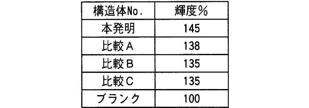
表1に示す結果から、本発明に係る輝度向上構造体は、優れた輝度向上性能を有することがわかる。
1 未延伸フィルム
2-1 右側のフィルム保持開始点
2-2 左側のフィルム保持開始点
3-1 右側のフィルム保持手段の軌跡
3-2 左側のフィルム保持手段の軌跡
4 テンター
5-1 右側のフィルム保持終了点
5-2 左側のフィルム保持終了点
6 斜め延伸フィルム
7-1 フィルムの送り方向
8-1 テンター入り口側のガイドロール
8-2 テンター出口側のガイドロール
9 フィルムの延伸方向
100 反射板
101 バックライト
102 基材(ポリエチレンテレフタレートフィルム)
103 配向膜
104 コレステリック液晶層
105 散乱層
106 空気層
107 C-プレート
108 λ/4位相差板
109 偏光子
110 偏光板保護フィルム
111 液晶セル
S 積分球
2-1 右側のフィルム保持開始点
2-2 左側のフィルム保持開始点
3-1 右側のフィルム保持手段の軌跡
3-2 左側のフィルム保持手段の軌跡
4 テンター
5-1 右側のフィルム保持終了点
5-2 左側のフィルム保持終了点
6 斜め延伸フィルム
7-1 フィルムの送り方向
8-1 テンター入り口側のガイドロール
8-2 テンター出口側のガイドロール
9 フィルムの延伸方向
100 反射板
101 バックライト
102 基材(ポリエチレンテレフタレートフィルム)
103 配向膜
104 コレステリック液晶層
105 散乱層
106 空気層
107 C-プレート
108 λ/4位相差板
109 偏光子
110 偏光板保護フィルム
111 液晶セル
S 積分球
Claims (2)
- バックライトと液晶セルとの間に、コレステリック液晶層、散乱板、λ/4位相差板および偏光子を有する液晶表示装置において、
前記λ/4位相差板と前記コレステリック液晶層との間に、少なくとも1つの前記散乱板が空気層と接するように介在していることを特徴とする、液晶表示装置。 - 前記空気層と接する前記散乱板の、前記空気層と接する面とは反対側の面が前記コレステリック液晶層と接するように、前記散乱板が配置されている、請求項1に記載の液晶表示装置。
Applications Claiming Priority (2)
| Application Number | Priority Date | Filing Date | Title |
|---|---|---|---|
| JP2011-014892 | 2011-01-27 | ||
| JP2011014892A JP2014074729A (ja) | 2011-01-27 | 2011-01-27 | 液晶表示装置 |
Publications (1)
| Publication Number | Publication Date |
|---|---|
| WO2012102325A1 true WO2012102325A1 (ja) | 2012-08-02 |
Family
ID=46580889
Family Applications (1)
| Application Number | Title | Priority Date | Filing Date |
|---|---|---|---|
| PCT/JP2012/051615 Ceased WO2012102325A1 (ja) | 2011-01-27 | 2012-01-26 | 液晶表示装置 |
Country Status (2)
| Country | Link |
|---|---|
| JP (1) | JP2014074729A (ja) |
| WO (1) | WO2012102325A1 (ja) |
Families Citing this family (1)
| Publication number | Priority date | Publication date | Assignee | Title |
|---|---|---|---|---|
| WO2020122117A1 (ja) * | 2018-12-13 | 2020-06-18 | 富士フイルム株式会社 | 積層体および画像表示装置 |
Citations (4)
| Publication number | Priority date | Publication date | Assignee | Title |
|---|---|---|---|---|
| JPH08146416A (ja) * | 1994-11-22 | 1996-06-07 | Sumitomo Chem Co Ltd | 液晶ディスプレイ用バックライト装置およびそれを用いた液晶表示装置 |
| JPH09297222A (ja) * | 1996-04-30 | 1997-11-18 | Nitto Denko Corp | 偏光光源装置及び液晶表示装置 |
| JP2002231027A (ja) * | 2001-01-30 | 2002-08-16 | Matsushita Electric Ind Co Ltd | 照明装置及びそれを用いた液晶表示装置 |
| JP2007148158A (ja) * | 2005-11-29 | 2007-06-14 | Nippon Zeon Co Ltd | 液晶表示装置 |
-
2011
- 2011-01-27 JP JP2011014892A patent/JP2014074729A/ja not_active Withdrawn
-
2012
- 2012-01-26 WO PCT/JP2012/051615 patent/WO2012102325A1/ja not_active Ceased
Patent Citations (4)
| Publication number | Priority date | Publication date | Assignee | Title |
|---|---|---|---|---|
| JPH08146416A (ja) * | 1994-11-22 | 1996-06-07 | Sumitomo Chem Co Ltd | 液晶ディスプレイ用バックライト装置およびそれを用いた液晶表示装置 |
| JPH09297222A (ja) * | 1996-04-30 | 1997-11-18 | Nitto Denko Corp | 偏光光源装置及び液晶表示装置 |
| JP2002231027A (ja) * | 2001-01-30 | 2002-08-16 | Matsushita Electric Ind Co Ltd | 照明装置及びそれを用いた液晶表示装置 |
| JP2007148158A (ja) * | 2005-11-29 | 2007-06-14 | Nippon Zeon Co Ltd | 液晶表示装置 |
Also Published As
| Publication number | Publication date |
|---|---|
| JP2014074729A (ja) | 2014-04-24 |
Similar Documents
| Publication | Publication Date | Title |
|---|---|---|
| CN101542364B (zh) | 液晶显示装置及层叠偏振板以及偏振光光源装置 | |
| KR100807140B1 (ko) | 광산란형 편광소자 및 광흡수형 편광소자가 적층된 편광판 | |
| KR20160148653A (ko) | 적층체 및 그 제조 방법, 편광판, 액정 표시 장치, 유기 el 표시 장치 | |
| JP2002372622A (ja) | 複合位相差板、円偏光板及び液晶表示装置、有機el表示装置 | |
| KR102140552B1 (ko) | 광학 소자, 광학 소자의 제조 방법 및 액정 표시 장치 | |
| JP4345312B2 (ja) | 広帯域1/4波長板原反、広帯域円偏光板原反、光学素子原反及び表示装置 | |
| KR20230030525A (ko) | 액정 조성물, 액정 경화층, 광학 필름, 편광판 및 화상 표시 장치 | |
| JP2018060152A (ja) | Ipsモード用の偏光板のセット及びそれを用いたipsモード液晶表示装置 | |
| JP2002372623A (ja) | 複合位相差板、円偏光板及び液晶表示装置、有機el表示装置 | |
| KR102513064B1 (ko) | 장척 위상차 필름, 장척 적층체, 화상 표시 장치 | |
| JP6227488B2 (ja) | 光学補償フィルム、偏光板、液晶表示装置および光学補償フィルムの製造方法 | |
| WO2017170019A1 (ja) | 偏光板のセット及びそれを用いたipsモード液晶表示装置 | |
| CN108885369B (zh) | 偏振板组和使用了该偏振板组的ips模式液晶显示装置 | |
| JP5326690B2 (ja) | 旋光板、およびこれが用いられた液晶表示装置 | |
| JP2004233988A (ja) | 広帯域コレステリック液晶フィルム、その製造方法、円偏光板、直線偏光子、照明装置および液晶表示装置 | |
| CN121969965A (zh) | 膜、光学部件、光学装置、头戴式显示器 | |
| JP2018060150A (ja) | Ipsモード用の偏光板のセット及びそれを用いたipsモード液晶表示装置 | |
| CN102770800B (zh) | Va-模式液晶显示装置 | |
| JP2002006139A (ja) | 偏光板、光散乱型偏光素子の製造方法および液晶表示装置 | |
| WO2012102325A1 (ja) | 液晶表示装置 | |
| JP6699514B2 (ja) | Ipsモード用の偏光板のセット及びそれを用いたipsモード液晶表示装置 | |
| JP5365184B2 (ja) | 液晶表示装置 | |
| JP2001281446A (ja) | 光学フイルム、偏光板および液晶表示装置 | |
| JP2017227776A (ja) | 液晶表示装置 | |
| JP2013020213A (ja) | 輝度向上フィルムとその製造方法、それを含む偏光板および液晶表示装置 |
Legal Events
| Date | Code | Title | Description |
|---|---|---|---|
| 121 | Ep: the epo has been informed by wipo that ep was designated in this application |
Ref document number: 12739231 Country of ref document: EP Kind code of ref document: A1 |
|
| NENP | Non-entry into the national phase |
Ref country code: DE |
|
| 122 | Ep: pct application non-entry in european phase |
Ref document number: 12739231 Country of ref document: EP Kind code of ref document: A1 |
|
| NENP | Non-entry into the national phase |
Ref country code: JP |