WO2012102230A1 - 放電灯 - Google Patents
放電灯 Download PDFInfo
- Publication number
- WO2012102230A1 WO2012102230A1 PCT/JP2012/051321 JP2012051321W WO2012102230A1 WO 2012102230 A1 WO2012102230 A1 WO 2012102230A1 JP 2012051321 W JP2012051321 W JP 2012051321W WO 2012102230 A1 WO2012102230 A1 WO 2012102230A1
- Authority
- WO
- WIPO (PCT)
- Prior art keywords
- tube
- protective tube
- main
- discharge lamp
- protective
- Prior art date
- Legal status (The legal status is an assumption and is not a legal conclusion. Google has not performed a legal analysis and makes no representation as to the accuracy of the status listed.)
- Ceased
Links
Images

Classifications
-
- H—ELECTRICITY
- H01—ELECTRIC ELEMENTS
- H01J—ELECTRIC DISCHARGE TUBES OR DISCHARGE LAMPS
- H01J61/00—Gas-discharge or vapour-discharge lamps
- H01J61/02—Details
- H01J61/30—Vessels; Containers
- H01J61/34—Double-wall vessels or containers
-
- H—ELECTRICITY
- H01—ELECTRIC ELEMENTS
- H01J—ELECTRIC DISCHARGE TUBES OR DISCHARGE LAMPS
- H01J61/00—Gas-discharge or vapour-discharge lamps
- H01J61/02—Details
- H01J61/50—Auxiliary parts or solid material within the envelope for reducing risk of explosion upon breakage of the envelope, e.g. for use in mines
-
- H—ELECTRICITY
- H01—ELECTRIC ELEMENTS
- H01J—ELECTRIC DISCHARGE TUBES OR DISCHARGE LAMPS
- H01J61/00—Gas-discharge or vapour-discharge lamps
- H01J61/82—Lamps with high-pressure unconstricted discharge having a cold pressure > 400 Torr
Definitions
- the present invention relates to a discharge lamp such as a high pressure mercury lamp, a metal halide lamp, or a high pressure sodium lamp.
- this type of high-pressure steam discharge lamp there are an arc tube in which a metal halide is filled and a pair of electrodes are arranged, and a metal halide lamp having an outer bulb portion that accommodates the arc tube.
- a metal halide lamp having an outer bulb portion that accommodates the arc tube.
- Patent Document 1 a protective tube is provided so as to surround the arc tube, and the fragments scattered by the burst of the arc tube are prevented from directly hitting the outer bulb, Thus, it has been considered that the outer sphere is prevented from being damaged.
- Patent Document 2 and Patent Document 3 a method of increasing the mechanical strength of the protective tube by winding a wire around the outer periphery of the protective tube, A method of increasing the mechanical strength of the protective tube by winding a mesh material around the outer periphery of the protective tube has been considered. It is also conceivable that the high-pressure steam discharge lamp has a quadruple tube structure by providing double protective tubes.
- the present invention has been made to solve the above-mentioned problems all at once, and it is possible to prevent damage to the outer bulb part due to breakage of the arc tube and prevent reduction in luminous efficiency without increasing the number of parts. Is the main issue.
- the discharge lamp according to the present invention includes a main tube portion that forms a discharge space and a thin tube portion that is provided at at least one end of the main tube portion and has an outer diameter smaller than that of the main tube portion.
- the inner surface of the protective tube has a curved surface that bulges to the main tube portion side.
- the curved surface is formed from one end side to the other end side of the main pipe portion on the inner surface of the protective tube. In this case, even when the arc tube is ruptured at an arbitrary position in the axial direction of the main tube portion, a curved surface is formed on the outer side corresponding to the position, and the protective tube is prevented from being damaged. It is possible to prevent the ball portion from being damaged.
- the protective tube for forming the curved surface in the entire circumferential direction of the protective tube and forming the curved surface from one end side to the other end side of the main tube portion on the inner surface of the protective tube, It is desirable that the cross-sectional opening perpendicular to the axial direction of the tube gradually decreases from the axial end of the protective tube toward the axial center.
- the protective tube has a concave portion recessed on the main tube side, and the curved surface Is preferably formed by the inner surface of the protective tube corresponding to the recess.
- the discharge lamp according to the present invention includes a main tube portion that forms a discharge space and a thin tube portion that is provided at least at one end of the main tube portion and has an outer diameter smaller than that of the main tube portion.
- the mechanical strength of the protective tube can be increased, and damage to the outer bulb due to breakage of the arc tube can be prevented.
- only the thick portion is provided on the side wall of the protective tube, and the number of parts is not increased, so that the assembly cost and the number of assembly steps are not increased.
- the mechanical strength can be increased in the circumferential direction of the protective tube.
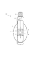
- Sectional drawing which shows the structure of the arc tube of the embodiment.
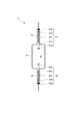
- Sectional drawing which shows the structure of the protective tube of the embodiment.
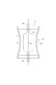
- Sectional drawing which shows the modification of a protective tube.
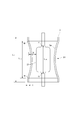
- Sectional drawing which shows the modification of a protective tube.
- a ceramic metal halide lamp 100 is formed of a light-transmitting ceramic such as light-transmitting alumina, and is filled with a metal halide as a light emitting material and a pair of electrodes 51. , 52 are disposed, a protective tube 3 provided so as to surround the arc tube 2, and an outer bulb portion 4 for housing the arc tube 2 and the protective tube 3.
- the arc tube 2 includes a main tube portion 21 that forms a discharge space S and a narrow tube portion 22 that is provided at both ends of the main tube portion 21 and has an outer diameter smaller than that of the main tube portion 21. I have.
- the arc tube 2 may be provided only at one end portion in addition to the thin tube portion 22 provided at both ends of the main tube portion.
- the main pipe portion 21 has a substantially straight pipe shape, and is formed such that both end portions thereof are reduced in diameter toward the end portion side. Further, a straight tubular thin tube portion 22 having an outer diameter smaller than that of the main tube portion 21 is connected to both ends of the main tube portion 21. In addition, the main pipe part 21 and the thin pipe part 22 are integrally molded by translucent ceramic.
- a rare gas, a metal halide and mercury (all not shown) are enclosed, and a pair of electrodes 51 and 52 are arranged.
- the pair of electrodes 51 and 52 includes a pair of electrode cores 511 and 521 formed in a rod shape from a heat-resistant metal such as tungsten, and the electrode cores 511 and 521 are inserted into the thin tube portions 22 respectively. As a result, the front end portion of the discharge space S is opposed to the end portion.
- the tip of the electrode cores 511 and 521 is a tip made of a heat-resistant metal such as tungsten for protecting the electrode cores 511 and 521 from the high temperature of the arc spot generated at the tip of the electrode cores 511 and 521 when the lamp is turned on.
- Coils 512 and 522 are wound.
- coils 513 and 523 in thin tubes made of a heat-resistant metal such as molybdenum are wound around the electrode cores 511 and 521 in the narrow tube portion 22 to release heat from the distal end portions of the poles 51 and 52 to the proximal end portion side. Has been.
- electrode support members 514 and 524 having corrosion resistance to the metal halide are connected to the base end portions of the electrode cores 511 and 521.
- the electrode supports 514 and 524 are airtightly fixed to the thin tube portion 22 by sealing materials 515 and 525 having corrosion resistance to metal halides, and are connected to a support frame 6 described later.
- the protective tube 3 receives fragments generated by the rupture of the main tube portion 21 in the arc tube 2, and is made of quartz glass or translucent alumina. Further, the protective tube 3 is provided so as to surround at least the main tube portion 21 of the arc tube 2, and has a substantially cylindrical shape with both ends opened. The protective tube 3 is provided coaxially or substantially coaxially with the arc tube 2 so that the center positions in the length direction (that is, the axial direction) coincide or substantially coincide. The detailed configuration of the protective tube 3 will be described later.
- the outer bulb portion 4 accommodates the arc tube 2 and the protective tube 3 and has a base 41 for supplying power to a pair of electrodes 51 and 52 provided on the arc tube 2.
- the outer sphere portion 4 is formed of transparent hard glass, and the central portion is substantially oval.
- a vacuum or an inert gas is sealed inside the outer sphere portion 4, and a base end portion of the outer sphere portion 4 is hermetically sealed by a stem 42, and a base 41 is attached to the stem 42.
- the outer bulb portion 4 is provided with a support frame 6 made of a metal rod for supporting the arc tube 2 and the protective tube 3 and supplying power to the pair of electrodes 51 and 52 in the arc tube 2.
- the support frame 6 has a base end connected to the stem 42 and a tip contacting the tip side inner wall of the outer bulb 4, so that the arc tube 2 and the protective tube 3 are connected to the center of the outer bulb 4. It is positioned and supported on the part.
- the protective tube 3 of the present embodiment has a concave portion 31 that is recessed toward the main pipe portion 21, and the main pipe portion is formed on the inner surface of the protective tube 3 corresponding to the main pipe portion 21.
- a curved surface 3a bulging toward the 21 side is formed.
- the recess 31 is an annular recess formed on the side peripheral wall of the protective tube 3 corresponding to the main pipe portion 21 and formed in the entire circumferential direction of the protective tube 3.
- the inner peripheral surface of the portion where the annular recess 31 is formed becomes the curved surface 3a.
- the curved surface 3 a is formed annularly in the entire circumferential direction on the inner peripheral surface of the protective tube 3, and the other end from one end side of the main pipe portion 21 on the inner peripheral surface of the protective tube 3. It is formed over the side.
- the protective tube 3 has a shape of a rotating body with a constricted central portion and a vertically symmetric shape with respect to the axial center, and the cross-sectional opening perpendicular to the axial direction is the axis of the protective tube 3. It gradually becomes smaller from the direction end to the axial center. Moreover, in this embodiment, it is comprised so that the most recessed part 31x (namely, top part of the curved surface 3a) of the recessed part 31 and the axial center position 21x of the main pipe part 21 may be located on the same plane.
- the axial length L 3a specific curved surface 3a is axially same as the length L 21 or greater formation of the main pipe section 21.
- the axial length L 3a of the curved surface 3a is the side wall of the main tube portion 21 (the side wall excluding the recess 31) side wall of the axial length L 3 and the protective pipe 3 of the protective tube 3 are those determined by the distance d or the like, larger distance d between the side wall of the protective tube 3 of the side wall and the main tube portion 21, it is conceivable to increase the axial length L 3a of the curved portion 3a.
- FIG. 1 As shown in FIG.
- the axial length L 21 of the main pipe portion 21 is a distance between the connection points P and Q of the narrow pipe portion 22 at both ends of the main pipe portion 21, and the axis of the curved surface 3 a.
- the direction length L 3a is a distance between the upper and lower bending start points M and N on the inner peripheral surface of the protective tube 3.
- the cross-sectional shape of the curved surface 3a (recessed portion 31) is a curved shape having a predetermined curvature such as a partial arc shape or a partial elliptical arc shape, and the curvature is the side peripheral wall of the protective tube 3 (the side peripheral wall excluding the concave portion 31). ) And the side wall of the main pipe portion 21, and the wall thickness t of the protective tube 3.
- the protective tube 3 of this embodiment when forming the protective tube 3 with quartz glass, the cylindrical body which consists of quartz glass is heated with a burner etc., and the center part is dented. To manufacture.
- the protective tube 3 is made of permeable alumina, it is manufactured by press molding using a mold.
- the ceramic metal halide lamp 100 configured as described above, by providing the curved surface 3a swelled on the main tube portion 21 side on the inner surface of the protective tube 3, the inner surface of the protective tube 3 is protected from the force from the inside.
- the mechanical strength can be increased. Therefore, since it is possible to prevent the protective tube 3 from being damaged by the fragments generated by the rupture of the main tube portion 21 in the arc tube 2, it is possible to prevent the outer bulb portion 4 from being damaged.
- the curved surface 3a is provided on the inner surface of the protective tube 3, and the wire and mesh material wound around the protective tube 3 can be dispensed with, and it is not necessary to form a quadruple tube structure. Therefore, a highly efficient ceramic metal halide lamp can be obtained.
- the present invention is not limited to the above embodiment.
- the present invention can be applied to various high-pressure steam discharge lamps such as a metal halide lamp using a quartz glass arc tube, a high-pressure mercury lamp, or a high-pressure sodium lamp in addition to a ceramic metal halide lamp.
- the curved surface 3a of the said embodiment is formed ranging from one end to the other end of the main pipe part 21, and is comprised so that the main pipe part 21 whole may be surrounded by the curved surface 3a, for example, the main pipe part 21 is comprised. It may be configured to surround a part of the main pipe part 21 such as a part including the axial center position 21x.
- the protective tube of the above embodiment forms one annular curved surface 3a on the inner peripheral surface of the protective tube 3 by forming one annular recess 31, but FIG. ),
- a plurality of curved surfaces 3a may be formed in the axial direction on the inner peripheral surface of the protective tube 3 by forming a plurality of annular recesses 31 in the axial direction.
- a plurality of concave portions 31 are formed in the circumferential direction on the side peripheral wall of the protective tube 3, thereby forming a plurality of curved surfaces 3a in the circumferential direction on the inner peripheral surface of the protective tube 3. You may make it do.
- the spiral curved surface 3 a may be formed on the inner peripheral surface of the protective tube 3 by forming the concave portion 31 in a spiral shape on the side peripheral wall of the protective tube 3.
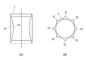
- the curved surface 3a In addition to forming the curved surface 3a by forming the recess 31 in the protective tube 3, as shown in FIG. 6 (A), a part of the side peripheral wall of the protective tube 3 corresponding to the main pipe portion 21 is partially formed.
- the curved surface 3 a may be formed on the inner peripheral surface of the protective tube 3 by forming the thick portion 32.
- the thick portion 32 is formed over the entire circumferential direction of the portion corresponding to the main pipe portion 21 on the side peripheral wall of the protective tube 3.
- a plurality of thick portions 32 may be formed in the circumferential direction on the outer peripheral surface of the side peripheral wall of the protective tube 3.
- the thick portion 32 is preferably formed from one end side to the other end side of the main pipe portion 21.
- the protective tube of the above embodiment has a cylindrical shape, but may have an elliptical cylindrical shape or a rectangular cylindrical shape.
- the present invention is applied to a ceramic metal halide lamp as an example of a high-pressure steam discharge lamp.
- a high-pressure steam discharge lamp such as a high-pressure mercury lamp or a high-pressure sodium lamp may be used.
- the present invention is not limited to a high pressure steam discharge lamp, and can be applied to various discharge lamps such as a low pressure steam discharge lamp.
- the present invention it is possible to provide a discharge lamp capable of preventing the outer bulb from being damaged due to the breakage of the arc tube and preventing the luminous efficiency from being lowered without increasing the number of parts.
Landscapes
- Vessels And Coating Films For Discharge Lamps (AREA)
Abstract
Description
2 ・・・発光管
21 ・・・本管部
22 ・・・細管部
S ・・・放電空間
51、52・・・一対の電極
3 ・・・保護管
3a ・・・湾曲面
31 ・・・凹部
4 ・・・外球部
Claims (7)
- 放電空間を形成する本管部及びこの本管部の少なくとも一端に設けられて前記本管部よりも小さい外径を有する細管部を備えており、前記放電空間内に一対の電極が設けられるとともに発光物質が封入された発光管と、
前記発光管の少なくとも本管部を包囲して設けられた概略筒形状をなす保護管と、
前記発光管及び前記保護管を収容する外球部とを具備し、
前記保護管の内面が、前記本管部側に膨出した湾曲面を有することを特徴とする放電灯。 - 前記湾曲面が、前記保護管の内面において周方向全体に環状に形成されている請求項1記載の放電灯。
- 前記湾曲面が、前記保護管の内面において前記本管部の一端側から他端側に亘って形成されている請求項1記載の放電灯。
- 前記保護管の軸方向に垂直な断面開口が、前記保護管の軸方向端部から軸方向中心に行くに従って徐々に小さくなるものである請求項1記載の放電灯。
- 前記保護管が前記本管部側に凹んでいる凹部を有しており、前記湾曲面が前記凹部に対応する保護管の内面により形成されている請求項1記載の放電灯。
- 放電空間を形成する本管部及びこの本管部の少なくとも一端に設けられて前記本管部よりも小さい外径を有する細管部を備えており、前記放電空間内に一対の電極が設けられるとともに発光物質が封入された発光管と、
前記発光管の少なくとも本管部を包囲して設けられた概略筒形状をなす保護管と、
前記発光管及び前記保護管を収容する外球部とを具備し、
前記保護管が、前記本管部に対応する側壁に部分的に肉厚部を有することを特徴とする放電灯。 - 前記肉厚部が、前記本管部に対応する側壁において周方向に複数設けられていることを特徴とする請求項6記載の放電灯。
Priority Applications (2)
| Application Number | Priority Date | Filing Date | Title |
|---|---|---|---|
| JP2012554780A JP5861648B2 (ja) | 2011-01-25 | 2012-01-23 | 放電灯 |
| KR1020137009896A KR20130138782A (ko) | 2011-01-25 | 2012-01-23 | 방전등 |
Applications Claiming Priority (2)
| Application Number | Priority Date | Filing Date | Title |
|---|---|---|---|
| JP2011012505 | 2011-01-25 | ||
| JP2011-012505 | 2011-01-25 |
Publications (1)
| Publication Number | Publication Date |
|---|---|
| WO2012102230A1 true WO2012102230A1 (ja) | 2012-08-02 |
Family
ID=46580797
Family Applications (1)
| Application Number | Title | Priority Date | Filing Date |
|---|---|---|---|
| PCT/JP2012/051321 Ceased WO2012102230A1 (ja) | 2011-01-25 | 2012-01-23 | 放電灯 |
Country Status (3)
| Country | Link |
|---|---|
| JP (1) | JP5861648B2 (ja) |
| KR (1) | KR20130138782A (ja) |
| WO (1) | WO2012102230A1 (ja) |
Citations (5)
| Publication number | Priority date | Publication date | Assignee | Title |
|---|---|---|---|---|
| JPH07142033A (ja) * | 1993-11-22 | 1995-06-02 | Matsushita Electron Corp | メタルハライドランプ |
| JPH1196974A (ja) * | 1997-09-18 | 1999-04-09 | Iwasaki Electric Co Ltd | 透明保温膜付メタルハライドランプ |
| JP2006228584A (ja) * | 2005-02-18 | 2006-08-31 | Iwasaki Electric Co Ltd | 高圧放電灯 |
| JP2007503086A (ja) * | 2003-08-18 | 2007-02-15 | コーニンクレッカ フィリップス エレクトロニクス エヌ ヴィ | 高圧放電ランプ |
| JP2009508316A (ja) * | 2005-09-14 | 2009-02-26 | ゼネラル・エレクトリック・カンパニイ | より低温の発光管を提供するためのガス充填シュラウド |
Family Cites Families (1)
| Publication number | Priority date | Publication date | Assignee | Title |
|---|---|---|---|---|
| US7423367B2 (en) * | 2005-08-25 | 2008-09-09 | Lantis Robert M | Design of high power pulsed flash lamps |
-
2012
- 2012-01-23 WO PCT/JP2012/051321 patent/WO2012102230A1/ja not_active Ceased
- 2012-01-23 JP JP2012554780A patent/JP5861648B2/ja not_active Expired - Fee Related
- 2012-01-23 KR KR1020137009896A patent/KR20130138782A/ko not_active Ceased
Patent Citations (5)
| Publication number | Priority date | Publication date | Assignee | Title |
|---|---|---|---|---|
| JPH07142033A (ja) * | 1993-11-22 | 1995-06-02 | Matsushita Electron Corp | メタルハライドランプ |
| JPH1196974A (ja) * | 1997-09-18 | 1999-04-09 | Iwasaki Electric Co Ltd | 透明保温膜付メタルハライドランプ |
| JP2007503086A (ja) * | 2003-08-18 | 2007-02-15 | コーニンクレッカ フィリップス エレクトロニクス エヌ ヴィ | 高圧放電ランプ |
| JP2006228584A (ja) * | 2005-02-18 | 2006-08-31 | Iwasaki Electric Co Ltd | 高圧放電灯 |
| JP2009508316A (ja) * | 2005-09-14 | 2009-02-26 | ゼネラル・エレクトリック・カンパニイ | より低温の発光管を提供するためのガス充填シュラウド |
Also Published As
| Publication number | Publication date |
|---|---|
| JPWO2012102230A1 (ja) | 2014-06-30 |
| JP5861648B2 (ja) | 2016-02-16 |
| KR20130138782A (ko) | 2013-12-19 |
Similar Documents
| Publication | Publication Date | Title |
|---|---|---|
| JP5360033B2 (ja) | ショートアーク型フラッシュランプ | |
| CN105632882B (zh) | 准分子放电灯装置 | |
| JP5861648B2 (ja) | 放電灯 | |
| JP4837605B2 (ja) | メタルハライドランプ | |
| JP5672562B2 (ja) | エキシマランプ | |
| JP5051401B2 (ja) | 高圧放電ランプ | |
| JP5919759B2 (ja) | セラミックメタルハライドランプ | |
| JP2008027745A (ja) | メタルハライドランプおよび照明装置 | |
| JP4791897B2 (ja) | セラミックメタルハライドランプおよび照明装置 | |
| JP5799437B2 (ja) | 外球保護構造を有する高輝度放電灯 | |
| JP5180265B2 (ja) | 金属蒸気放電ランプおよび照明装置 | |
| JP5126618B2 (ja) | 高圧放電ランプ | |
| JP2007273373A (ja) | メタルハライドランプおよび照明装置 | |
| JP2005183164A (ja) | 放電ランプ装置用アークチューブ | |
| CN207852614U (zh) | 放电灯 | |
| JP2017216158A (ja) | ロングアーク型放電ランプ | |
| JP3976051B2 (ja) | 高圧放電灯 | |
| JP2017216145A (ja) | 放電ランプ | |
| JP2013254636A (ja) | 高圧放電ランプ | |
| JP5907004B2 (ja) | Hidランプ | |
| JP2007134330A (ja) | メタルハライドアーク放電ランプ | |
| JP2020091941A (ja) | ショートアーク型放電ランプ | |
| WO2009144904A1 (ja) | 反射鏡付放電ランプ | |
| JP2010177104A (ja) | 高圧放電ランプおよび照明装置 | |
| JP2015153602A (ja) | 高圧放電ランプ |
Legal Events
| Date | Code | Title | Description |
|---|---|---|---|
| 121 | Ep: the epo has been informed by wipo that ep was designated in this application |
Ref document number: 12739203 Country of ref document: EP Kind code of ref document: A1 |
|
| ENP | Entry into the national phase |
Ref document number: 2012554780 Country of ref document: JP Kind code of ref document: A |
|
| ENP | Entry into the national phase |
Ref document number: 20137009896 Country of ref document: KR Kind code of ref document: A |
|
| NENP | Non-entry into the national phase |
Ref country code: DE |
|
| 122 | Ep: pct application non-entry in european phase |
Ref document number: 12739203 Country of ref document: EP Kind code of ref document: A1 |