WO2012102097A1 - めっき処理装置、めっき処理方法および記憶媒体 - Google Patents
めっき処理装置、めっき処理方法および記憶媒体 Download PDFInfo
- Publication number
- WO2012102097A1 WO2012102097A1 PCT/JP2012/050597 JP2012050597W WO2012102097A1 WO 2012102097 A1 WO2012102097 A1 WO 2012102097A1 JP 2012050597 W JP2012050597 W JP 2012050597W WO 2012102097 A1 WO2012102097 A1 WO 2012102097A1
- Authority
- WO
- WIPO (PCT)
- Prior art keywords
- plating solution
- plating
- substrate
- temperature
- supply
- Prior art date
- Legal status (The legal status is an assumption and is not a legal conclusion. Google has not performed a legal analysis and makes no representation as to the accuracy of the status listed.)
- Ceased
Links
Images




Classifications
-
- B—PERFORMING OPERATIONS; TRANSPORTING
- B05—SPRAYING OR ATOMISING IN GENERAL; APPLYING FLUENT MATERIALS TO SURFACES, IN GENERAL
- B05C—APPARATUS FOR APPLYING FLUENT MATERIALS TO SURFACES, IN GENERAL
- B05C5/00—Apparatus in which liquid or other fluent material is projected, poured or allowed to flow on to the surface of the work
- B05C5/001—Apparatus in which liquid or other fluent material is projected, poured or allowed to flow on to the surface of the work incorporating means for heating or cooling the liquid or other fluent material
-
- C—CHEMISTRY; METALLURGY
- C23—COATING METALLIC MATERIAL; COATING MATERIAL WITH METALLIC MATERIAL; CHEMICAL SURFACE TREATMENT; DIFFUSION TREATMENT OF METALLIC MATERIAL; COATING BY VACUUM EVAPORATION, BY SPUTTERING, BY ION IMPLANTATION OR BY CHEMICAL VAPOUR DEPOSITION, IN GENERAL; INHIBITING CORROSION OF METALLIC MATERIAL OR INCRUSTATION IN GENERAL
- C23C—COATING METALLIC MATERIAL; COATING MATERIAL WITH METALLIC MATERIAL; SURFACE TREATMENT OF METALLIC MATERIAL BY DIFFUSION INTO THE SURFACE, BY CHEMICAL CONVERSION OR SUBSTITUTION; COATING BY VACUUM EVAPORATION, BY SPUTTERING, BY ION IMPLANTATION OR BY CHEMICAL VAPOUR DEPOSITION, IN GENERAL
- C23C18/00—Chemical coating by decomposition of either liquid compounds or solutions of the coating forming compounds, without leaving reaction products of surface material in the coating; Contact plating
- C23C18/16—Chemical coating by decomposition of either liquid compounds or solutions of the coating forming compounds, without leaving reaction products of surface material in the coating; Contact plating by reduction or substitution, e.g. electroless plating
- C23C18/1601—Process or apparatus
- C23C18/1619—Apparatus for electroless plating
-
- B—PERFORMING OPERATIONS; TRANSPORTING
- B05—SPRAYING OR ATOMISING IN GENERAL; APPLYING FLUENT MATERIALS TO SURFACES, IN GENERAL
- B05D—PROCESSES FOR APPLYING FLUENT MATERIALS TO SURFACES, IN GENERAL
- B05D1/00—Processes for applying liquids or other fluent materials
- B05D1/02—Processes for applying liquids or other fluent materials performed by spraying
-
- C—CHEMISTRY; METALLURGY
- C23—COATING METALLIC MATERIAL; COATING MATERIAL WITH METALLIC MATERIAL; CHEMICAL SURFACE TREATMENT; DIFFUSION TREATMENT OF METALLIC MATERIAL; COATING BY VACUUM EVAPORATION, BY SPUTTERING, BY ION IMPLANTATION OR BY CHEMICAL VAPOUR DEPOSITION, IN GENERAL; INHIBITING CORROSION OF METALLIC MATERIAL OR INCRUSTATION IN GENERAL
- C23C—COATING METALLIC MATERIAL; COATING MATERIAL WITH METALLIC MATERIAL; SURFACE TREATMENT OF METALLIC MATERIAL BY DIFFUSION INTO THE SURFACE, BY CHEMICAL CONVERSION OR SUBSTITUTION; COATING BY VACUUM EVAPORATION, BY SPUTTERING, BY ION IMPLANTATION OR BY CHEMICAL VAPOUR DEPOSITION, IN GENERAL
- C23C18/00—Chemical coating by decomposition of either liquid compounds or solutions of the coating forming compounds, without leaving reaction products of surface material in the coating; Contact plating
- C23C18/16—Chemical coating by decomposition of either liquid compounds or solutions of the coating forming compounds, without leaving reaction products of surface material in the coating; Contact plating by reduction or substitution, e.g. electroless plating
- C23C18/1601—Process or apparatus
- C23C18/1603—Process or apparatus coating on selected surface areas
- C23C18/1614—Process or apparatus coating on selected surface areas plating on one side
-
- C—CHEMISTRY; METALLURGY
- C23—COATING METALLIC MATERIAL; COATING MATERIAL WITH METALLIC MATERIAL; CHEMICAL SURFACE TREATMENT; DIFFUSION TREATMENT OF METALLIC MATERIAL; COATING BY VACUUM EVAPORATION, BY SPUTTERING, BY ION IMPLANTATION OR BY CHEMICAL VAPOUR DEPOSITION, IN GENERAL; INHIBITING CORROSION OF METALLIC MATERIAL OR INCRUSTATION IN GENERAL
- C23C—COATING METALLIC MATERIAL; COATING MATERIAL WITH METALLIC MATERIAL; SURFACE TREATMENT OF METALLIC MATERIAL BY DIFFUSION INTO THE SURFACE, BY CHEMICAL CONVERSION OR SUBSTITUTION; COATING BY VACUUM EVAPORATION, BY SPUTTERING, BY ION IMPLANTATION OR BY CHEMICAL VAPOUR DEPOSITION, IN GENERAL
- C23C18/00—Chemical coating by decomposition of either liquid compounds or solutions of the coating forming compounds, without leaving reaction products of surface material in the coating; Contact plating
- C23C18/16—Chemical coating by decomposition of either liquid compounds or solutions of the coating forming compounds, without leaving reaction products of surface material in the coating; Contact plating by reduction or substitution, e.g. electroless plating
- C23C18/1601—Process or apparatus
- C23C18/1633—Process of electroless plating
- C23C18/1675—Process conditions
- C23C18/1676—Heating of the solution
-
- C—CHEMISTRY; METALLURGY
- C23—COATING METALLIC MATERIAL; COATING MATERIAL WITH METALLIC MATERIAL; CHEMICAL SURFACE TREATMENT; DIFFUSION TREATMENT OF METALLIC MATERIAL; COATING BY VACUUM EVAPORATION, BY SPUTTERING, BY ION IMPLANTATION OR BY CHEMICAL VAPOUR DEPOSITION, IN GENERAL; INHIBITING CORROSION OF METALLIC MATERIAL OR INCRUSTATION IN GENERAL
- C23C—COATING METALLIC MATERIAL; COATING MATERIAL WITH METALLIC MATERIAL; SURFACE TREATMENT OF METALLIC MATERIAL BY DIFFUSION INTO THE SURFACE, BY CHEMICAL CONVERSION OR SUBSTITUTION; COATING BY VACUUM EVAPORATION, BY SPUTTERING, BY ION IMPLANTATION OR BY CHEMICAL VAPOUR DEPOSITION, IN GENERAL
- C23C18/00—Chemical coating by decomposition of either liquid compounds or solutions of the coating forming compounds, without leaving reaction products of surface material in the coating; Contact plating
- C23C18/16—Chemical coating by decomposition of either liquid compounds or solutions of the coating forming compounds, without leaving reaction products of surface material in the coating; Contact plating by reduction or substitution, e.g. electroless plating
- C23C18/1601—Process or apparatus
- C23C18/1633—Process of electroless plating
- C23C18/1675—Process conditions
- C23C18/168—Control of temperature, e.g. temperature of bath, substrate
-
- H—ELECTRICITY
- H10—SEMICONDUCTOR DEVICES; ELECTRIC SOLID-STATE DEVICES NOT OTHERWISE PROVIDED FOR
- H10P—GENERIC PROCESSES OR APPARATUS FOR THE MANUFACTURE OR TREATMENT OF DEVICES COVERED BY CLASS H10
- H10P14/00—Formation of materials, e.g. in the shape of layers or pillars
- H10P14/40—Formation of materials, e.g. in the shape of layers or pillars of conductive or resistive materials
- H10P14/46—Formation of materials, e.g. in the shape of layers or pillars of conductive or resistive materials using a liquid
-
- C—CHEMISTRY; METALLURGY
- C25—ELECTROLYTIC OR ELECTROPHORETIC PROCESSES; APPARATUS THEREFOR
- C25D—PROCESSES FOR THE ELECTROLYTIC OR ELECTROPHORETIC PRODUCTION OF COATINGS; ELECTROFORMING; APPARATUS THEREFOR
- C25D17/00—Constructional parts, or assemblies thereof, of cells for electrolytic coating
- C25D17/001—Apparatus specially adapted for electrolytic coating of wafers, e.g. semiconductors or solar cells
-
- G—PHYSICS
- G03—PHOTOGRAPHY; CINEMATOGRAPHY; ANALOGOUS TECHNIQUES USING WAVES OTHER THAN OPTICAL WAVES; ELECTROGRAPHY; HOLOGRAPHY
- G03F—PHOTOMECHANICAL PRODUCTION OF TEXTURED OR PATTERNED SURFACES, e.g. FOR PRINTING, FOR PROCESSING OF SEMICONDUCTOR DEVICES; MATERIALS THEREFOR; ORIGINALS THEREFOR; APPARATUS SPECIALLY ADAPTED THEREFOR
- G03F7/00—Photomechanical, e.g. photolithographic, production of textured or patterned surfaces, e.g. printing surfaces; Materials therefor, e.g. comprising photoresists; Apparatus specially adapted therefor
- G03F7/16—Coating processes; Apparatus therefor
- G03F7/162—Coating on a rotating support, e.g. using a whirler or a spinner
-
- H—ELECTRICITY
- H10—SEMICONDUCTOR DEVICES; ELECTRIC SOLID-STATE DEVICES NOT OTHERWISE PROVIDED FOR
- H10P—GENERIC PROCESSES OR APPARATUS FOR THE MANUFACTURE OR TREATMENT OF DEVICES COVERED BY CLASS H10
- H10P72/00—Handling or holding of wafers, substrates or devices during manufacture or treatment thereof
- H10P72/04—Apparatus for manufacture or treatment
- H10P72/0402—Apparatus for fluid treatment
Definitions
- the present invention relates to a plating apparatus, a plating method, and a storage medium for supplying a plating solution to the surface of a substrate to perform a plating process.
- wirings are formed on a substrate such as a semiconductor wafer or a liquid crystal substrate in order to form a circuit on the surface.
- This wiring is made of a copper material having a low electrical resistance and high reliability instead of an aluminum material.
- copper is more easily oxidized than aluminum, it is desirable to perform plating with a metal having high electromigration resistance in order to prevent oxidation of the copper wiring surface.
- the plating process is performed, for example, by supplying an electroless plating solution to the surface of the substrate on which the copper wiring is formed. For example, by fixing the substrate to the substrate rotation holding mechanism and supplying the electroless plating solution while rotating the substrate rotation holding mechanism, a uniform flow of the plating solution is formed on the surface of the substrate. Thus, the plating process is uniformly performed over the entire surface of the substrate (for example, Patent Document 1).
- the plating process by electroless plating is affected by reaction conditions such as the composition of the plating solution and temperature. Moreover, it is known that the plating solution heated to the plating temperature generates particles by reaction. For this reason, when the plating solution before being supplied to the substrate is held at a temperature higher than the plating temperature for a long time, there is a problem that the quality of the plating solution is lowered and the life of the plating solution is shortened.
- An object of the present invention is to provide a plating apparatus, a plating method, and a storage medium that can effectively solve such problems.
- the present invention provides a plating apparatus for performing a plating process by supplying a plating solution to a substrate, and supplying a plating solution having a predetermined temperature to the substrate accommodating portion that accommodates the substrate and the substrate accommodated in the substrate accommodating portion.
- a discharge nozzle that discharges the plating solution to the substrate, and a plating solution supply pipe that supplies the plating solution of the supply tank to the discharge nozzle, and the supply tank of the plating solution supply mechanism or the A first heating mechanism for heating the plating solution to a first temperature lower than the predetermined temperature is attached to at least one of the plating solution supply pipes, and the first heating mechanism Further, on the discharge nozzle side, a second heating mechanism for heating the plating solution to a second temperature equal to or higher than the predetermined temperature is attached to the plating solution supply pipe. It is a plating processing apparatus.
- the predetermined temperature of the plating solution supplied to the substrate is equal to a plating temperature at which a self-reaction proceeds in the plating solution, or a temperature higher than the plating temperature. Also good.
- the first heating mechanism may include a supply tank circulation heating means for heating the plating solution in the supply tank to a first temperature.
- the supply tank circulation heating means is attached to the supply tank circulation pipe for circulating the plating solution in the supply tank and the supply tank circulation pipe, and supplies the plating solution to the first temperature.
- a heater a heater.
- the supply tank circulation pipe of the supply tank circulation heating means may be connected to the plating solution supply pipe in the vicinity of the second heating mechanism.
- the first heating mechanism is attached to the plating solution supply pipe so as to reach the vicinity of the second heating mechanism along the plating solution supply pipe, and heats the plating solution to the first temperature. You may have the heating means for supply pipes.
- the second heating mechanism includes a second temperature medium supply unit that heats a predetermined heat transfer medium to a second temperature, and the plating solution closer to the discharge nozzle than the first heating mechanism.
- a temperature controller attached to the supply pipe and configured to heat the plating solution to a second temperature using heat of the heat transfer medium from the second temperature medium supply means.
- the second heating mechanism may further include first temperature medium supply means for heating the heat transfer medium to a first temperature.
- the second heating mechanism may send the heat transfer medium from the first temperature medium supply unit to the temperature controller after the discharge of the plating solution from the discharge nozzle is stopped.
- the first heating mechanism is attached to the plating solution supply pipe so as to reach the vicinity of the second heating mechanism along the plating solution supply pipe, and heats the plating solution to the first temperature.
- You may have the heating means for supply pipes.
- the heating means for the supply pipe may be a heating pipe attached around the plating solution supply pipe, and the second heating mechanism stops the discharge of the plating solution from the discharge nozzle. Then, the heat transfer medium from the first temperature medium supply means may be sent to the heating pipe of the supply pipe heating means of the first heating mechanism.
- the plating apparatus may further include a physical cleaning mechanism that cleans the substrate by applying a physical force to the substrate.
- the physical cleaning mechanism applies a physical force to the substrate to clean the substrate after the plating solution is supplied to the substrate and before the substrate is dried. Also good.
- the present invention provides a plating method for performing a plating process by supplying a plating solution to a substrate, placing the substrate in a substrate container, and supplying a plating solution in a supply tank to the substrate at a predetermined temperature via a discharge nozzle.
- the plating solution in the supply tank is supplied to the substrate at the predetermined temperature via the discharge nozzle, the plating solution is firstly at a first temperature lower than the predetermined temperature. And then heated to a second temperature equal to or higher than the predetermined temperature, and then supplied to the substrate through the discharge nozzle. is there.
- the predetermined temperature of the plating solution supplied to the substrate is equal to a plating temperature at which a self-reaction proceeds in the plating solution, or a temperature higher than the plating temperature. Also good.
- the plating solution supplied to the substrate may be heated to a first temperature in a supply tank circulation pipe for circulating the plating solution in the supply tank.
- the plating solution in the supply tank when the plating solution in the supply tank is supplied to the substrate through the discharge nozzle, the plating solution is first heated to the first temperature by the first heating mechanism, and then The second heating mechanism disposed on the discharge nozzle side of the first heating mechanism may be heated to the second temperature, and then supplied to the substrate through the discharge nozzle.
- the plating solution heated to the second temperature by the second heating mechanism is cooled to the first temperature. Good.
- the plating method according to the present invention may further include cleaning the substrate by applying a physical force to the substrate.
- the plating method according to the present invention may further include drying the substrate.
- applying the physical force to the substrate to clean the substrate may be performed after supplying the plating solution to the substrate and before drying the substrate.
- the present invention relates to a storage medium storing a computer program for causing a plating apparatus to execute a plating method, wherein the plating method is a method of supplying a plating solution to a substrate and performing the plating process.
- the plating method is a method of supplying a plating solution to a substrate and performing the plating process.
- the substrate container Supplying a plating solution in a supply tank to the substrate through a discharge nozzle at a predetermined temperature, and when the plating solution in the supply tank is supplied to the substrate at a predetermined temperature through the discharge nozzle.
- the plating solution is first heated to a first temperature lower than the predetermined temperature, then heated to a second temperature equal to or higher than the predetermined temperature, and then the discharge nozzle is turned on.
- the storage medium is characterized in that the storage medium is supplied to the substrate via a method.
- the plating solution can be heated to the second temperature in two stages. For this reason, the life of the plating solution can be made sufficiently long.
- FIG. 1 is a plan view showing a schematic configuration of a plating system according to the first embodiment of the present invention.
- FIG. 2 is a side view showing the plating apparatus according to the first embodiment of the present invention.
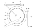
- FIG. 3 is a plan view of the plating apparatus shown in FIG.
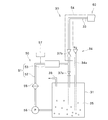
- FIG. 4 is a view showing a plating solution supply mechanism in the first embodiment of the present invention.
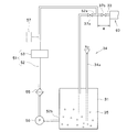
- FIG. 5 is a view showing a plating solution supply mechanism in the first embodiment of the present invention.
- FIG. 6 is a diagram showing a two-fluid nozzle of the droplet discharge means in the first embodiment of the present invention.
- FIG. 7 is a diagram showing a first heating mechanism in the first embodiment of the present invention.
- FIG. 8 is a diagram showing a second heating mechanism in the first embodiment of the present invention.
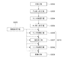
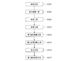
- FIG. 9 is a flowchart showing a plating method.
- FIG. 10 is a flowchart showing in detail the Ni plating step of FIG.
- FIG. 11 is a view showing a modification of the first heating mechanism.
- FIG. 12 is a view showing a modification of the physical cleaning mechanism.
- FIG. 13 shows a plating solution recovery mechanism in the second embodiment of the present invention.
- FIG. 14 is a flowchart showing in detail the Ni plating step in the second embodiment of the present invention.
- the plating system 1 mounts a carrier 3 that accommodates a plurality of substrates 2 (here, 25 semiconductor wafers) (for example, 25 wafers), and carries in a predetermined number of substrates 2. And a substrate loading / unloading chamber 5 for unloading and a substrate processing chamber 6 for performing various processes such as plating and cleaning of the substrate 2.
- the substrate carry-in / out chamber 5 and the substrate processing chamber 6 are provided adjacent to each other.
- the substrate carry-in / out chamber 5 includes a carrier placement unit 4, a transfer chamber 9 that stores the transfer device 8, and a substrate transfer chamber 11 that stores a substrate transfer table 10.
- the transfer chamber 9 and the substrate delivery chamber 11 are connected to each other via a delivery port 12.
- the carrier placement unit 4 places a plurality of carriers 3 that accommodate a plurality of substrates 2 in a horizontal state.
- the substrate 2 is transferred, and in the substrate transfer chamber 11, the substrate 2 is transferred to and from the substrate processing chamber 6.
- a predetermined number of substrates 2 are transported by the transport device 8 between any one carrier 3 placed on the carrier platform 4 and the substrate delivery table 10.
- the substrate processing chamber 6 is arranged in the front and back on one side and the other side of the substrate transfer unit 13 and extends in the front and back in the central portion, and supplies the plating solution to the substrate 2 to perform the plating process.
- a plurality of plating processing apparatuses 20 are arranged in the front and back on one side and the other side of the substrate transfer unit 13 and extends in the front and back in the central portion, and supplies the plating solution to the substrate 2 to perform the plating process.
- a plurality of plating processing apparatuses 20 is arranged in the front and back on one side and the other side of the substrate transfer unit 13 and extends in the front and back in the central portion, and supplies the plating solution to the substrate 2 to perform the plating process.
- the substrate transport unit 13 includes a substrate transport device 14 configured to be movable in the front-rear direction.
- the substrate transfer unit 13 communicates with the substrate transfer table 10 in the substrate transfer chamber 11 via the substrate transfer port 15.
- the substrates 2 are transferred to the respective plating processing apparatuses 20 in a state where the substrates 2 are held horizontally one by one by the substrate transfer device 14 of the substrate transfer unit 13. Then, in each plating processing apparatus 20, the substrate 2 is subjected to cleaning processing and plating processing one by one.
- Each plating apparatus 20 differs only in the plating solution used, and the other points have substantially the same configuration. Therefore, in the following description, the configuration of one plating processing apparatus 20 among the plurality of plating processing apparatuses 20 will be described.
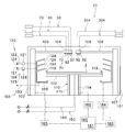
- FIG. 2 is a side view showing the plating apparatus 20
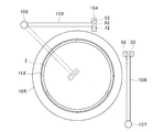
- FIG. 3 is a plan view showing the plating apparatus 20.
- the plating apparatus 20 includes a substrate rotation holding mechanism (substrate housing portion) 110 for rotating and holding the substrate 2 inside the casing 101, and a plating solution and a cleaning solution on the surface of the substrate 2.
- a substrate rotation holding mechanism substrate housing portion
- the liquid supply mechanisms 30, 30 A, 90, 90 A for supplying the liquid
- the liquid discharge mechanisms 120, 125, 130 for discharging the plating solution, the cleaning solution, etc. scattered from the substrate 2.
- a physical cleaning mechanism 70 for cleaning the surface of the substrate 2 a substrate rotation holding mechanism 110, liquid supply mechanisms 30, 30 A, 90, 90 A, a liquid discharge mechanism 120, 125, 130, and a control mechanism 160 for controlling the physical cleaning mechanism 70.
- a control mechanism 160 for controlling the physical cleaning mechanism 70.
- the substrate rotation holding mechanism 110 includes a hollow cylindrical rotation shaft 111 extending vertically in the casing 101, and a turntable 112 attached to the upper end portion of the rotation shaft 111. And a wafer chuck 113 that is provided on the outer peripheral portion of the upper surface of the turntable 112 and supports the substrate 2, and a rotation mechanism 162 that rotates the rotation shaft 111.
- the rotation mechanism 162 is controlled by the control mechanism 160, and the rotation shaft 111 is rotationally driven by the rotation mechanism 162, whereby the substrate 2 supported by the wafer chuck 113 is rotated.
- the liquid supply mechanisms 30, 30A, 90, and 90A that supply a plating solution, a cleaning solution, and the like to the surface of the substrate 2 will be described with reference to FIGS.
- the liquid supply mechanisms 30, 30 ⁇ / b> A, 90, and 90 ⁇ / b> A are a plating liquid supply mechanism 30 that supplies a plating solution containing Ni to the surface of the substrate 2, and a cleaning processing solution that supplies a cleaning processing solution for post-cleaning to the surface of the substrate 2.
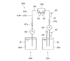
- the plating solution supply mechanism 30 includes a supply tank 31 that stores a plating solution 35 that is supplied to the substrate 2 at a predetermined temperature, a discharge nozzle 32 that discharges the plating solution 35 to the substrate 2, and A plating solution supply pipe 33 that supplies the plating solution 35 of the supply tank 31 to the discharge nozzle 32 and a supply tank that is connected to the supply tank 31 and removes dissolved oxygen and dissolved hydrogen in the plating solution 35 stored in the supply tank 31.
- Use deaeration means 34 As shown in FIG. 4, an openable / closable valve 37 b is inserted in the plating solution supply pipe 33.
- the “predetermined temperature” of the plating solution 35 supplied to the substrate 2 is a temperature equal to or higher than the plating temperature at which the self-reaction proceeds in the plating solution 35. It has become. The plating temperature will be described later.
- Various chemicals are supplied to the supply tank 31 from a plurality of chemical supply sources (not shown) in which various components of the plating solution 35 such as Ni are stored.
- chemical solutions such as NiP metal salts containing Ni ions, reducing agents and additives are supplied.
- the flow rates of the various chemical solutions are adjusted so that the components of the plating solution 35 stored in the supply tank 31 are appropriately adjusted.
- the discharge nozzle 32 is attached to the nozzle head 104.
- the nozzle head 104 is attached to the tip of an arm 103.
- the arm 103 can be extended in the vertical direction and is fixed to a support shaft 102 that is rotationally driven by a rotation mechanism 165. . With such a configuration, the plating solution can be discharged from a desired height to any location on the surface of the substrate 2 via the discharge nozzle 32.
- the plating solution supply mechanism 30 is shown to be disposed outside the arm 103.
- the arrangement of the plating solution supply mechanism 30 is not particularly limited, and the plating solution supply mechanism 30 may be arranged inside the arm 103. In the example described later, a case where the plating solution supply pipe of the plating solution supply mechanism 30 is disposed inside the arm 103 will be described.
- the arrangement of the plating solution supply mechanism 30A, the cleaning treatment solution supply mechanism 90, the cleaning treatment solution supply mechanism 90A, or the physical cleaning mechanism 70 shown in FIG. 2 is not particularly limited.
- a first heating mechanism 50 for heating the plating solution 35 to the first temperature is attached to at least one of the supply tank 31 and the plating solution supply pipe 33 of the plating solution supply mechanism 30.
- a second heating mechanism 60 that heats the plating solution 35 to a second temperature higher than the first temperature is attached to the plating solution supply pipe 33 on the discharge nozzle 32 side of the first heating mechanism 50.
- the supply tank degassing means 34, the first heating mechanism 50, and the second heating mechanism 60 will be described in detail later.
- plating solution supply mechanism 30A As shown in FIG. 5, in the plating solution supply mechanism 30A, the components for supplying the plating solution to the discharge nozzle 32 are different only in the plating solution 35A used, and the other components are the plating solution supply mechanism 30. It is substantially the same as each component in. As shown in FIG. 2, the discharge nozzle 32 that discharges a plating solution containing Pd onto the surface of the substrate 2 is attached to the nozzle head 109. The nozzle head 109 is attached to the tip of the arm 108, and the arm 108 can be extended in the vertical direction and is fixed to the support shaft 107 that is rotationally driven by the rotation mechanism 163. With such a configuration, the plating solution can be discharged from a desired height to any location on the surface of the substrate 2 via the discharge nozzle 32.
- the same parts as those of the plating solution supply mechanism 30 are denoted by the same reference numerals, and detailed description thereof is omitted.
- the cleaning processing liquid supply mechanism 90 is used in the post-cleaning step of the substrate 2 and includes a nozzle 92 attached to the nozzle head 104 as shown in FIG.
- the cleaning processing liquid supply mechanism 90 includes a tank 91 that stores the cleaning processing liquid 93 supplied to the substrate 2, and a supply pipe 94 that supplies the cleaning processing liquid 93 in the tank 91 to the nozzle 92. And a pump 96 and a valve 97a inserted in the supply pipe 94. As shown in FIG.
- the supply pipe 94 and the nozzle 92 are shared with a rinse process liquid supply mechanism 95 that supplies a rinse process liquid such as pure water to the surface of the substrate 2. May be.
- a rinse process liquid supply mechanism 95 that supplies a rinse process liquid such as pure water to the surface of the substrate 2.
- the cleaning liquid supply mechanism 90A is used in a pre-cleaning step of the substrate 2 and includes a nozzle 92 attached to the nozzle head 109 as shown in FIG.
- the components of the cleaning process liquid supply mechanism 90A differ only in the cleaning process liquid 93A used, and the other components are substantially the same as those in the cleaning process liquid supply mechanism 90. ing.
- the cleaning processing liquid supply mechanism 90A shown in FIG. 5 the same parts as those in the cleaning processing liquid supply mechanism 90 are denoted by the same reference numerals, and detailed description thereof is omitted.
- liquid discharge mechanism 120, 125, and 130 for discharging the plating solution and the cleaning solution scattered from the substrate 2 will be described with reference to FIG.
- a cup 105 that is driven up and down by an elevating mechanism 164 and has outlets 124, 129, and 134 is disposed in the casing 101.
- the liquid discharge mechanisms 120, 125, and 130 discharge the liquid collected at the discharge ports 124, 129, and 134, respectively.
- the treatment liquid splashed from the substrate 2 can be discharged by the liquid discharge mechanisms 120, 125, and 130 through the discharge ports 124, 129, and 134 for each type.
- the liquid discharge mechanism 120 is the plating liquid discharge mechanism 120 that discharges the plating liquid 35
- the liquid discharge mechanism 125 is the plating liquid discharge mechanism 125 that discharges the plating liquid 35 ⁇ / b> A
- the liquid discharge mechanism 130 Is a treatment liquid discharge mechanism 130 for discharging the cleaning treatment liquids 93, 93A and the rinse treatment liquid.
- the plating solution discharge mechanisms 120 and 125 have recovery flow paths 122 and 127 and discard flow paths 123 and 128 that are switched by flow path switches 121 and 126, respectively.
- the recovery channels 122 and 127 are channels for recovering and reusing the plating solution
- the discard channels 123 and 128 are channels for discarding the plating solution.
- a plating solution recovery mechanism for reusing the plating solution recovered by the recovery flow paths 122 and 127 will be described later in a second embodiment.
- the treatment liquid discharge mechanism 130 is provided with only the waste flow path 133.
- the physical cleaning mechanism 70 cleans the surface of the substrate 2 by applying a physical force to the surface of the substrate 2 and includes, for example, a droplet discharge means 71 that discharges a droplet of cleaning liquid.
- the droplet discharge means 71 applies physical force to the surface of the substrate 2 by droplets after the surface of the substrate 2 is plated and before the surface of the substrate 2 is dried.
- the control mechanism 160 controls the application.
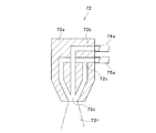
- the droplet discharge means 71 constituting the physical cleaning mechanism 70 includes a two-fluid nozzle 72 that discharges droplets of the cleaning liquid 74 onto the surface of the substrate 2, a tank 76 that stores the cleaning liquid 74, and a tank A supply pipe 74 a for supplying the cleaning liquid 74 of 76 to the two-fluid nozzle 72, a pump 77 and a valve 78 a inserted in the supply pipe 74 a, and a supply for supplying a droplet generating gas 75 such as nitrogen to the two-fluid nozzle 72 A tube 75a.
- the two-fluid nozzle 72 is attached to the nozzle head 104.
- the nozzle head 104 can be moved via the arm 103 and the rotation mechanism 165. For this reason, the droplet of the cleaning liquid 74 can be transferred to any arbitrary surface on the surface of the substrate 2 via the two-fluid nozzle 72. It is possible to discharge to places.
- the liquid supplied to the two-fluid nozzle 72 via the supply pipe 74a may be a rinse treatment liquid such as pure water instead of the cleaning liquid 74. In this case, either the cleaning liquid 74 or the rinse treatment liquid is selectively supplied to the two-fluid nozzle 72 by appropriately controlling the opening and closing of the valves 78a and 78b.
- the two-fluid nozzle 72 generally refers to a nozzle of a type that generates minute droplets by mixing gas and liquid and discharges these minute droplets.
- a region indicated by a two-dot chain line indicates a spray range of the droplet 72 f of the spray cleaning liquid 74 sprayed from the two-fluid nozzle 72.
- the two-fluid nozzle 72 has a substantially cylindrical nozzle main body 72a. Inside the nozzle main body 72a, a cleaning liquid flow path 72b communicating with a supply pipe 74a to which the cleaning liquid 74 is supplied, and a droplet generating unit. A gas flow path 72c communicating with a supply pipe 75a to which the gas 75 is supplied is provided, and the cleaning liquid 74 and the droplet generation gas 75 are collided and mixed by the mixing unit 72d. As a result, droplets of the cleaning liquid 74 are formed in the mixing unit 72d, and the droplets 72f of the cleaning liquid 74 are discharged to the substrate 2.
- the supply tank degassing means 34 includes a gas supply pipe 34 a that supplies an inert gas such as nitrogen into the supply tank 31.
- a part of the inert gas such as nitrogen introduced into the plating solution 35 through the gas supply pipe 34 a is dissolved in the plating solution 35.
- the maximum amount of gas that can be dissolved in the plating solution 35 is determined according to the temperature or the like. Therefore, when an inert gas such as nitrogen is newly dissolved in the plating solution 35, the plating solution 35 is already dissolved. Other gases such as oxygen and hydrogen dissolved therein are discharged to the outside of the plating solution 35.
- the supply tank deaeration means 34 including the gas supply pipe 34a is for removing dissolved oxygen and dissolved hydrogen in the plating solution 35 by so-called bubbling. Oxygen and hydrogen discharged from the plating solution 3 are discharged from the supply tank 31 by the exhaust means 38.
- the gas supply pipe 34 a is inserted not to the vicinity of the liquid level of the plating solution 35 stored in the supply tank 31 but to the vicinity of the bottom surface of the supply tank 31.
- dissolved oxygen and dissolved hydrogen can be removed over the entire area of the plating solution 35 in the supply tank 31.
- concentration of dissolved oxygen and dissolved hydrogen in the plating solution 35 supplied to the substrate 2 can be further reduced.
- the upper end of the supply tank 31 is sealed from the external environment by some sealing means, and an inert gas such as nitrogen is filled between the sealing means and the surface of the plating solution 35. Also good. That is, the plating solution 35 in the supply tank 31 may be placed in an inert gas atmosphere such as nitrogen. As a result, the plating solution 35 after the dissolved oxygen and dissolved hydrogen are removed can be prevented from being exposed to oxygen and hydrogen.
- FIG. 7 shows a first heating mechanism 50 having a supply tank circulation heating means 51 for heating the plating solution 35 to a first temperature.
- the first temperature is a predetermined temperature that is lower than the temperature (plating temperature) at which the deposition of metal ions due to self-reaction in the plating solution 35 proceeds and higher than room temperature.
- the plating temperature is about 60 degrees, and in this case, the first temperature is set within a range of 40 to 60 degrees.
- the supply tank circulation heating means 51 is attached to the supply tank circulation pipe 52 for circulating the plating solution 35 in the vicinity of the supply tank 31, and the supply tank circulation pipe 52. And a supply tank heater 53 for heating to a first temperature. As shown in FIG. 7, a pump 56 for circulating the plating solution 35 and a filter 55 are interposed in the supply tank circulation pipe 52. By providing such a supply tank circulation heating means 51, the plating solution 35 in the supply tank 31 can be heated to the first temperature while circulating in the vicinity of the supply tank 31. Further, as shown in FIG. 7, a plating solution supply pipe 33 is connected to the supply tank circulation pipe 52. In this case, when the valve 37 a shown in FIG.
- the supply tank circulation pipe 52 may be provided with monitoring means 57 for monitoring the characteristics of the plating solution 35.
- the monitor means 57 includes, for example, a temperature monitor that monitors the temperature of the plating solution 35, a pH monitor that monitors the pH of the plating solution 35, and the like.
- the second heating mechanism 60 is for heating the plating solution 35 heated to the first temperature by the first heating mechanism 50 to the second temperature.
- the second temperature is a predetermined temperature that is equal to or higher than the plating temperature described above.
- the plating temperature is about 60 degrees as described above, and in this case, the second temperature is set within the range of 60 to 90 degrees.
- the second heating mechanism 60 includes a second temperature medium supply unit 61 that heats a predetermined heat transfer medium to a second temperature or a temperature higher than the second temperature, and the first heating mechanism 50.
- a temperature controller 62 attached to the plating solution supply pipe 33 on the discharge nozzle 32 side and configured to conduct heat of the heat transfer medium from the second temperature medium supply means 61 to the plating solution 35 in the plating solution supply pipe 33. is doing. Further, as shown in FIG. 8, even if a temperature holder 65 is further provided for holding the plating solution 35 provided at the arm 103 and passing through the plating solution supply pipe 33 located in the arm 103 at the second temperature. Good. In FIG.
- the plating solution supply pipe located in the temperature controller 62 is denoted by reference numeral 33a, and the plating solution supply pipe located in the temperature holder 65 (in the arm 103) is shown. It is represented by reference numeral 33b.
- the temperature controller 62 has a supply port 62a for introducing a heat transfer medium for temperature adjustment (for example, hot water) supplied from the second temperature medium supply means 61, and a discharge port 62b for discharging the heat transfer medium. ing.
- the heat transfer medium supplied from the supply port 62 a contacts the plating solution supply pipe 33 a while flowing through the space 62 c inside the temperature controller 62. As a result, the plating solution 35 flowing through the plating solution supply pipe 33a is heated to the second temperature.
- the heat transfer medium after being used for heating the plating solution 35 is discharged from the discharge port 62b.
- the plating solution supply pipe 33a in the temperature controller 62 is formed in a spiral shape as shown in FIG.
- the contact area between the heat transfer medium and the plating solution supply pipe 33a can be increased, whereby the heat of the heat transfer medium can be efficiently transferred to the plating solution 35.
- the temperature holder 65 disposed between the temperature controller 62 and the discharge nozzle 32 is a plating heated to the second temperature by the temperature controller 62 until the plating solution 35 is discharged from the discharge nozzle 32. This is for maintaining the temperature of the liquid 35.
- the temperature holder 65 includes a heat retaining pipe 65 c extending in contact with the plating solution supply pipe 33 b in the temperature holder 65 and a heat transfer medium supplied from the second temperature medium supply means 61. It has the supply port 65a introduced into the heat insulation pipe 65c, and the discharge port 65b which discharges
- the heat retaining pipe 65c extends to the immediate vicinity of the discharge nozzle 32 along the plating solution supply pipe 33b, whereby the temperature of the plating solution 35 immediately before being discharged from the discharge nozzle 32 can be maintained at the second temperature. .
- the heat retaining pipe 65 c may be opened inside the nozzle head 104 that houses the discharge nozzle 32 and may communicate with a space 65 d in the temperature retainer 65.
- the temperature holder 65 includes the plating solution supply pipe 33b located at the center of the cross section, the heat retaining pipe 65c disposed in thermal contact with the outer periphery of the plating solution supply pipe 33b, and the outer periphery of the heat retaining pipe 65c. It has a triple structure (structure of triple piping) consisting of a space 65d located in the area.
- the heat transfer medium supplied from the supply port 65 a keeps the plating solution 35 through the heat insulation pipe 65 c until reaching the nozzle head 104, and then is discharged from the discharge port 65 b through the space 65 d in the temperature holder 65.
- the heat transfer medium flowing through the space 65d thermally shuts off the heat transfer medium flowing through the heat retaining pipe 65c (and the plating solution 35 flowing through the plating solution supply pipe 33b inside it) and the atmosphere outside the temperature holder 65. do. Therefore, heat loss of the heat transfer medium flowing through the heat retaining pipe 65c can be suppressed, and heat transfer from the heat transfer medium flowing through the heat retaining pipe 65c to the plating liquid 35 flowing through the plating liquid supply pipe 33b can be efficiently performed.
- the heat transfer medium supplied to the temperature controller 62 and the heat transfer medium supplied to the temperature holder 65 are both the heat transfer medium supplied from the second temperature medium supply means 61.
- An example is shown.
- the present invention is not limited to this, and the heat transfer medium supplied to the temperature controller 62 and the heat transfer medium supplied to the temperature holder 65 are supplied from separate heat transfer medium sources. Also good.
- the second heating mechanism 60 heats the heat transfer medium to the first temperature in addition to the second temperature medium supply means 61 that heats and supplies the heat transfer medium to the second temperature. You may further have the 1st temperature medium supply means 63 to supply. In this case, the second heating mechanism 60 causes the heat transfer medium from the second temperature medium supply means 61 to be sent to the temperature controller 62 and the temperature holder 65 while the plating solution 35 is being discharged from the discharge nozzle 32. It is controlled by the control mechanism 160.
- the second heating mechanism 60 is configured so that the heat transfer medium at the first temperature from the first temperature medium supply means 63 is the temperature controller 62 and the temperature holding. It is controlled by the control mechanism 160 so as to be sent to the device 65.
- the plating solution 35 remaining in the temperature controller 62 and the temperature holder 65 can be cooled and held to the first temperature.
- the remaining plating solution 35 at the first temperature lower than the plating temperature, it is possible to prevent the plating solution 35 from being deteriorated by heat, thereby extending the life of the plating solution 35. can do.
- the second temperature medium supply means 61 is provided in the heat transfer medium supply pipe 66 that sends the heat transfer medium to the temperature controller 62 and the temperature holder 65 as shown in FIG.
- Flow path switching mechanisms 66a and 66b for selectively communicating either the second temperature heat transfer medium from the first temperature transfer medium or the first temperature heat transfer medium from the first temperature medium supply means 63 to the heat transfer medium supply pipe 66. Is provided. As a result, the temperature of the plating solution 35 in the temperature controller 62 and the temperature holder 65 can be selectively controlled to the first temperature or the second temperature.
- the plating apparatus 20 further includes a back surface treatment liquid supply mechanism 145 that supplies a treatment liquid to the back surface of the substrate 2 and a back surface gas supply mechanism 150 that supplies gas to the back surface of the substrate 2. You may do it.
- the plating processing system 1 including a plurality of plating processing apparatuses 20 configured as described above is driven and controlled by the control mechanism 160 according to various programs recorded in the storage medium 161 provided in the control mechanism 160, whereby the substrate 2 is controlled. Various processes are performed.
- the storage medium 161 stores various setting data and various programs such as a plating processing program described later.
- known media such as a computer-readable memory such as ROM and RAM, and a disk-shaped storage medium such as a hard disk, CD-ROM, DVD-ROM, and flexible disk can be used.
- the plating processing system 1 and the plating processing apparatus 20 are driven and controlled to perform plating processing on the substrate 2 in accordance with the plating processing program recorded in the storage medium 161.
- the plating processing program recorded in the storage medium 161. first, a method for preparing chemical reduction plating by degassing and heating a Ni plating solution used in chemical reduction plating will be described.
- Ni plating is performed by chemical reduction plating, and then gold plating is performed on the substrate 2 with displacement plating with the other plating processing apparatus 20.
- a method will be described.
- the degassing step (S313) for removing dissolved oxygen and dissolved hydrogen in the plating solution 35 stored in the supply tank 31 will be described.
- nitrogen is introduced into the supply tank 31 through the gas supply pipe 34a.
- dissolved oxygen and dissolved hydrogen in the plating solution 35 stored in the supply tank 31 are replaced with dissolved nitrogen.
- the dissolved oxygen and dissolved hydrogen in the plating solution 35 are removed.
- the plating solution 35 heated to the second temperature is sent to the discharge nozzle 32 via the arm 103 as shown in FIG.
- the arm 103 is provided with a temperature holder 65, and a heat transfer medium heated to the second temperature is supplied from the second temperature medium supply means 61 to the temperature holder 65. For this reason, the plating solution 35 is held at the second temperature until it reaches the discharge nozzle 32 through the plating solution supply pipe 33 b inside the temperature holder 65.
- the present invention is not limited to this.
- the plating solution 35 is heated to a temperature higher than the first temperature and lower than the second temperature while passing through the plating solution supply pipe 33a inside the temperature controller 62, and then the plating solution 35 is kept at a temperature.
- the plating solution supply pipe 33b inside the vessel 65 it may be heated to the second temperature.
- the plating solution 35 is heated to the second temperature immediately before reaching the discharge nozzle 32. Accordingly, the period during which the plating solution 35 is held at the second temperature before being discharged from the discharge nozzle 32 can be further shortened.
- the plating solution 35 remaining in the temperature controller 62 and the temperature holder 65 is cooled to the first temperature and held (first temperature holding step). S317).
- the second heating mechanism 60 is controlled by the control mechanism 160 so that the heat transfer medium having the first temperature from the first temperature medium supply unit 63 is sent to the temperature regulator 62 and the temperature holder 65.
- Plating treatment method Next, a method of performing Pd plating on the substrate 2 by displacement plating in one plating processing apparatus 20 and then applying Ni plating prepared as described above by chemical reduction plating is shown in FIG. The description will be given with reference.
- a substrate carrying-in process and a substrate receiving process are performed.
- the cup 105 is lowered to a predetermined position, and then the loaded substrate 2 is supported by the wafer chuck 113, and then the discharge port 134 and the outer peripheral edge of the substrate 2 face each other.
- the cup 105 is raised by the elevating mechanism 164 to the position.
- a cleaning process including a rinsing process, a pre-cleaning process, and a subsequent rinsing process is executed (S302).
- the valve 97b of the rinsing process liquid supply mechanism 95A is opened, whereby the rinsing process liquid is supplied to the surface of the substrate 2 through the nozzle 92.
- a pre-cleaning process is performed.
- the valve 97a of the cleaning processing liquid supply mechanism 90A is opened, whereby the cleaning processing liquid 93 is supplied to the surface of the substrate 2 through the nozzle 92.
- the rinse treatment liquid is supplied to the surface of the substrate 2 through the nozzle 92 in the same manner as described above.
- the rinse treatment liquid and the cleaning treatment liquid 93 after the treatment are discarded through the discharge port 134 of the cup 105 and the disposal flow path 133 of the treatment liquid discharge mechanism 130.
- the valve 97a is closed.
- Pd plating process Next, a Pd plating process is performed (S303). This Pd plating process is executed as a displacement plating process while the substrate 2 after the pre-cleaning process is not dried. In this way, by performing the displacement plating process in a state where the substrate 2 is not dried, it is possible to prevent the copper on the surface to be plated of the substrate 2 from being oxidized and failing to perform a satisfactory displacement plating process. it can.
- the cup 105 is raised by the elevating mechanism 164 to a position where the discharge port 129 and the outer peripheral edge of the substrate 2 face each other.
- the valve 37b of the plating solution supply mechanism 30A is opened, whereby the plating solution 35A containing Pd is discharged onto the surface of the substrate 2 through the discharge nozzle 32 at a desired flow rate.
- Pd plating is performed on the surface of the substrate 2 by displacement plating.
- the treated plating solution 35 ⁇ / b> A is discharged from the discharge port 129 of the cup 105.
- the treated plating solution 35A is recovered via the recovery channel 127 or discarded via the discard channel 128.
- the valve 37b is closed.
- a rinsing process is performed (S304). Since the rinsing process S304 is substantially the same as the rinsing process in the above-described cleaning process S302, detailed description thereof is omitted.
- Ni plating process Thereafter, the Ni plating process is performed in the same plating apparatus 20 that has performed the above-described processes S302 to 304 (S305). This Ni plating process is performed as a chemical reduction plating process.
- the plating solution 35 from which dissolved oxygen and dissolved hydrogen are removed by the supply tank degassing means 34 and heated to the second temperature by the second heating mechanism 60 is discharged. It discharges with the desired flow volume from the nozzle 32 (discharge process S316). As a result, Ni plating is applied to the surface of the substrate 2 by chemical reduction plating. At this time, the cup 105 is raised by the elevating mechanism 164 to a position where the discharge port 124 and the outer peripheral edge of the substrate 2 face each other, so that the treated plating solution 35 is discharged from the discharge port 124 of the cup 105. Is done. The discharged plating solution 35 after processing is collected in the collection tank through the collection channel 122 or discarded through the disposal channel 123.
- a cleaning process including a rinsing process S306, a post-cleaning process S307, and a rinsing process S308 is performed (S310).
- a rinsing process is performed on the surface of the substrate 2 that has been subjected to the Ni plating process (S306).
- the valve 97b of the rinsing treatment liquid supply mechanism 95 is opened, whereby the rinsing treatment liquid is supplied to the surface of the substrate 2 via the nozzle 92.
- a post-cleaning step is executed (S307).
- the valve 97a of the cleaning processing liquid supply mechanism 90 is opened, whereby the cleaning processing liquid 93 is supplied to the surface of the substrate 2 through the nozzle 92.
- the rinse treatment liquid and the cleaning treatment liquid 93 after the treatment are discarded through the discharge port 134 of the cup 105 and the disposal flow path 133 of the treatment liquid discharge mechanism 130.
- the valve 97a is closed.
- rinse process Next, a rinsing process is performed (S308). Since this rinse process step S308 is substantially the same as the above-described rinse process step S306, detailed description thereof will be omitted.
- a drying process for drying the substrate 2 is performed (S309).
- the turntable 112 when the turntable 112 is rotated, the liquid adhering to the substrate 2 is blown outward by centrifugal force, thereby drying the substrate 2. That is, the turntable 112 may have a function as a drying mechanism that dries the surface of the substrate 2.
- the surface of the substrate 2 is first subjected to Pd plating by displacement plating, and then Ni plating by chemical reduction plating.
- the gold plating method is substantially the same as the above-described method for the Pd plating process except that the plating solution and the cleaning solution are different, and thus detailed description thereof is omitted.
- the supply tank 31 that stores the plating solution 35 supplied to the discharge nozzle 32 is adjusted after the components of various chemicals are adjusted.
- a supply tank deaeration means 34 for removing dissolved oxygen and dissolved hydrogen in the plating solution 35 is provided.
- concentration of the dissolved oxygen in the plating solution 35 can be reduced, and the lifetime of the plating solution 35 can be lengthened by this.
- concentration of dissolved hydrogen in the plating solution 35 can be reduced, thereby preventing the metal ions in the plating solution from being reduced by the reducing action of hydrogen, and the reduced metal ions are reduced to copper. Precipitation near the wiring can be prevented. This can improve process stability.
- the first heating mechanism 50 that heats the plating solution 35 to the first temperature and the second heating mechanism 60 that heats the plating solution 35 to the second temperature are provided. ing. That is, the plating solution 35 is heated to the second temperature in two stages. The effect by this is demonstrated based on contrast with a comparative example.
- the plating solution heated to the second temperature is held in the supply tank for a long time.
- the time for which the plating solution 35 is held at the second temperature higher than the plating temperature becomes longer, the oxidation of the metal ions in the plating solution 35 proceeds, thereby shortening the life of the plating solution 35. Conceivable. Further, it is conceivable that metal ions are precipitated while the plating solution is held at the second temperature, causing particles.
- the time for which the plating solution 35 is held at the second temperature can be shortened.
- the life of the plating solution 35 can be extended. Further, the generation of particles can be suppressed.
- the plating solution is held at room temperature in the supply tank, and the plating solution is heated to the second temperature in the arm or the like before being discharged from the discharge nozzle. think of.
- the time required for heating is long.
- the plating solution 35 in the supply tank 31 is heated to the first temperature in advance. For this reason, the plating solution 35 can be quickly heated to the second temperature with small energy. Thereby, the throughput of the process can be improved while suppressing the precipitation of metal ions.
- the concentration of dissolved oxygen in the plating solution 35 is reduced, and the plating solution 35 in the supply tank 31 is held at the first temperature. Therefore, according to the present embodiment, the life of the plating solution 35 can be remarkably improved by a synergistic effect based on these combinations.
- Defects tend to gather in the vicinity of the formed plating film. In the middle or immediately after the plating process, it is considered that a liquid such as a plating solution or a cleaning solution is interposed between the plating film and the defect.
- the physical cleaning process (S320) is performed after the rinsing process (S308) is performed and before the drying process (S309) is performed.
- the physical cleaning mechanism 70 is controlled by the control mechanism 160.
- the valve 78a is opened, whereby the cleaning liquid 74 is supplied to the two-fluid nozzle 72 via the supply pipe 74a.
- the droplet generating gas 75 is supplied to the two-fluid nozzle 72 via the supply pipe 75a.
- droplets of the cleaning liquid 74 are generated, and the droplets are discharged toward the substrate 2.
- a rinse treatment liquid is interposed between the plating film and the defect.
- the physical cleaning mechanism 70 that applies physical force to the surface of the substrate 2 is provided.
- the physical cleaning mechanism 70 is a control mechanism that applies physical force to the surface of the substrate 2 in a state where the liquid is interposed between the plating film and the defect before the surface of the substrate 2 is dried. 160. For this reason, a physical force can be applied to the defect while the liquid is interposed between the plating film and the defect. As a result, defects can be easily removed from the plating film.
- the defect may be adsorbed to the metal film.
- the distance between the plating film and the defect is shortened, and it is considered that it is difficult to remove the defect from the plating film. Therefore, it is preferable to use the physical cleaning mechanism 70 while a rinse treatment liquid, a cleaning treatment liquid, a plating solution, or the like is interposed between the plating film and the defect.
- the physical cleaning process (S320) is performed after the rinsing process (S308) is performed and before the drying process (S309) is performed is shown.
- the physical cleaning process (S320) can be executed at various timings before the surface of the substrate 2 is dried.
- the physical cleaning step (S320) may be performed after the Ni plating step (S305) is performed and before the rinse treatment step (S306) is performed.
- the physical cleaning step (S320) may be performed after the rinsing process (S306) is performed and before the post-cleaning step (S307) is performed.
- the physical cleaning step (S320) may be performed after the post-cleaning step (S307) is performed and before the rinsing process step (S308) is performed.
- a liquid such as a plating solution, a rinsing treatment solution, or a cleaning treatment solution is interposed between the plating film and the defect, so that the defect can be easily removed from the plating film.
- the physical cleaning step (S320) is performed when not the cleaning processing solution but the rinsing processing solution is interposed between the plating film and the defect. Thereby, it is possible to prevent the cleaning treatment liquid from being scattered by physical force.
- the post-cleaning step (S307) may be executed as the physical cleaning step (S320). That is, the cleaning treatment liquid 93 used in the post-cleaning process (S307) may be used as the cleaning liquid 74 used in the physical cleaning process (S320). In this case, droplets of the cleaning treatment liquid 93 are ejected from the two-fluid nozzle 72 to the substrate 2. As a result, the substrate 2 is post-cleaned and defects are removed from the plating film. Moreover, a rinse process process (S308) may be performed as a physical washing process (S320).
- a rinsing process liquid such as pure water used in the rinsing process (S308) may be used as the cleaning liquid 74 used in the physical cleaning process (S320).
- a rinsing process liquid such as pure water used in the rinsing process (S308) may be used as the cleaning liquid 74 used in the physical cleaning process (S320).
- droplets of the rinsing process liquid are ejected from the two-fluid nozzle 72 to the substrate 2.
- the substrate 2 is rinsed, and the defects are removed from the plating film.
- the supply tank deaeration means 34 removes dissolved oxygen and dissolved hydrogen in the plating solution 35 by bubbling.
- the present invention is not limited to this, and various means for removing the dissolved gas in the liquid can be adopted as the supply tank deaeration means 34.
- a means may be used in which the temperature of the plating solution 35 is once lowered, thereby reducing the amount of gas that can be dissolved in the plating solution 35, thereby removing the dissolved gas in the plating solution 35.
- the example in which the plating solution 35 is heated to the first temperature in the vicinity of the supply tank 31 by the supply tank circulation heating means 51 of the first heating mechanism 50 is shown.
- the means for heating the plating solution 35 to the first temperature in the vicinity of the supply tank 31 is not limited to the supply tank circulation heating means 51, and various means can be used.
- a heater for heating the plating solution 35 to the first temperature may be provided in the supply tank 31.
- the present invention is not limited to this, and the plating solution 35 may be heated to the first temperature until it reaches the vicinity of the second heating mechanism 60.
- the supply tank circulation pipe 52 of the supply tank circulation heating means 51 may be connected to the plating solution supply pipe 33 in the vicinity of the second heating mechanism 60.
- the temperature of the plating solution 35 decreases until the second heating mechanism 60 is reached. Can be prevented. This makes it possible to more reliably heat the plating solution 35 to the second temperature quickly with small energy.
- “in the vicinity of the second heating mechanism 60” means, for example, that the distance w (see FIG. 11) from the supply tank circulation pipe 52 to the second heating mechanism 60 is 1 m or less.
- the plating solution 35 that passes through the plating solution supply pipe 33 as indicated by a one-dot chain line in FIG. 7.
- a supply pipe heating means 54 for holding at a first temperature.
- the supply pipe heating means 54 may be a rubber heater attached to the plating solution supply pipe 33 and heated to the first temperature.
- the supply pipe heating means 54 may be a heating pipe that is provided in contact with the plating solution supply pipe 33 and that passes a heat transfer medium such as hot water heated to the first temperature.
- the first temperature medium supply unit 63 of the second heating mechanism 60 may be used. That is, as indicated by the one-dot chain line in FIG. 8, the heat transfer medium having the first temperature is supplied by the first temperature medium supply means 63 to the supply pipe heating means 54 disposed in the vicinity of the second heating mechanism 60. 59 may be supplied.
- the first temperature medium supply means 63 provided for controlling the temperature of the temperature controller 62 and the temperature holder 65 to the first temperature after the discharge of the plating solution 35 from the discharge nozzle 32 is stopped, It may be used to supply the heat transfer medium having the first temperature to the supply pipe heating means 54 during the discharge of the plating solution 35.
- the temperature of the plating solution 35 can be prevented from decreasing before reaching the second heating mechanism 60, and the components of the plating apparatus 20 can be reduced.
- the heat transfer medium having the first temperature is supplied to the supply pipe heating means 54 via the supply pipe 59 by the first temperature medium supply means 63. Good.
- the plating solution 35 remaining in the plating solution supply pipe 33 located on the supply tank 31 side with respect to the second heating mechanism 60 is transferred to the first temperature. Can be held in. In this case, even immediately after the discharge of the plating solution 35 is resumed, the plating solution 35 reaching the second heating mechanism 60 is heated to the first temperature.
- the plating solution 35 can be easily and quickly heated to the second temperature by the second heating mechanism 60. As a result, the amount of useless plating solution 35 that is discharged from the discharge nozzle 32 before reaching the second temperature can be reduced. As a result, the time until the plating process can be started can be shortened, thereby improving the throughput of the process.
- the droplet discharge means 71 for discharging the droplet of the cleaning liquid 74 is used as the physical cleaning mechanism 70 .
- the present invention is not limited to this, and means for applying a physical force to the surface of the substrate 2 by other methods may be used.
- a physical cleaning mechanism 70 instead of the droplet discharge means 71 having the two-fluid nozzle 72, a cleaning brush 79 having a brush portion 79a that contacts the surface of the substrate 2, a high-pressure nozzle, or an ultrasonic wave A nozzle may be used.
- the physical cleaning mechanism 70 is defective while a liquid such as the plating solution 35 is interposed between the plating film and the defect. Apply physical force to it. As a result, defects can be easily removed from the plating film.
- the plating apparatus 20 can apply various plating solutions to the surface of the substrate 2 by chemical reduction plating.
- a plating solution containing Co plating solution such as CoWB, CoWP, CoB, CoP
- the first temperature and the second temperature are appropriately set according to the plating temperature of the plating solution.
- the plating temperature is 50 to 70 degrees
- the first temperature is set within the range of 40 degrees to the above plating temperature
- the second temperature is The plating temperature is set within a range of 90 degrees.
- the plating solution supply mechanism 30A is also provided with the first heating mechanism 50 and the second heating mechanism 60 as in the case of the plating solution supply mechanism 30, and also for the plating solution 35A containing Pd.
- two-stage heating by the first heating mechanism 50 and the second heating mechanism 60 may be performed.
- the present invention as an example of the plating process in one plating apparatus 20, an example is shown in which Pd plating is performed on the substrate 2 by displacement plating, and then Ni plating is performed by chemical reduction plating (FIG. 9). (See S302 to S309).
- the present invention is not limited to this, and only chemical reduction plating may be performed as the plating process in the one plating apparatus 20. In this case, among the steps shown in FIG. 9, steps other than S303 and S304 are performed.
- the plating solution for chemical reduction plating is not particularly limited, and various plating solutions for chemical reduction plating such as CoWB, CoWP, CoB, CoP, and NiP can be used.
- the treated plating solution containing Ni recovered by the recovery flow path 122 of the plating solution discharge mechanism 120 is reused.
- a plating solution recovery mechanism 80 for reusing the treated plating solution will be described with reference to FIG.
- the plating solution recovery mechanism 80 is connected to the recovery tank 88 that stores the processed plating solution 85 discharged from the plating solution discharge mechanism 120, and the recovery tank 88. And a recovery tank deaeration means 84 that removes dissolved oxygen and dissolved hydrogen in the plating solution 85 stored in 88.
- the recovery tank degassing means 84 includes a gas supply pipe 84 a for supplying an inert gas such as nitrogen into the recovery tank 88, as with the above-described supply tank degassing means 34. That is, the recovery tank deaeration means 84 is for removing dissolved oxygen and dissolved hydrogen in the plating solution 85 by so-called bubbling.
- the configurations and operational effects of the recovery tank degassing means 84 and the gas supply pipe 84a are substantially the same as the configurations and operational effects of the supply tank degassing means 34 and the gas supply pipe 34a, and thus detailed description thereof is omitted.
- the plating solution recovery mechanism 80 agitates the replenishing means 88 a for adding a component that is insufficient to the processed plating solution 85 discharged from the plating solution discharge mechanism 120 and the plating solution 85 stored in the recovery tank 88.
- a stirring means 81 agitates the replenishing means 88a for replenishing the plating solution 85 with a chemical solution such as a NiP metal salt containing Ni ions, a reducing agent, and an additive to appropriately adjust the components of the plating solution 85.
- a monitoring unit 87b for monitoring the characteristics of the plating solution 85 may be provided in the collection tank 88, as indicated by a one-dot chain line in FIG. .
- the monitor means 87b is composed of, for example, a pH monitor that monitors the pH of the plating solution 85.
- the agitating means 81 agitates the plating solution 85 by circulating the plating solution 85 in the vicinity of the recovery tank 88, for example, as shown in FIG.
- a stirring means 81 has a recovery tank circulation pipe 82 whose one end 82a and the other end 82b are connected to a recovery tank 88, and a pump inserted in the recovery tank circulation pipe 82. 86 and a filter 89.
- various impurities contained in the plating solution can be removed while stirring the plating solution 85. For example, impurities (particles) that can become nuclei when metal ions are precipitated from the plating solution can be removed.
- a connecting pipe 83 for supplying the plating solution 85 to the supply tank 31 is attached to the stirring means 81.
- the plating solution 85 after processing used for performing the Ni plating processing on the substrate 2 scatters from the substrate 2 and reaches the discharge port 124.
- the processed plating solution 85 that has reached the discharge port 124 is sent to the recovery tank 88 via the recovery flow path 122 of the liquid discharge mechanism 120 (S321).
- the lacking component is added to the plating solution 85 after processing using the above-described replenishing means (S322). At this time, the plating solution 85 is stirred using the stirring means 81 so that the added component and the treated plating solution 85 are sufficiently mixed.
- the dissolved oxygen and dissolved hydrogen in the plating solution 85 stored in the collection tank 88 are removed (S323). Specifically, as shown in FIG. 13, nitrogen is introduced into the recovery tank 88 via the gas supply pipe 84a. Thereby, the dissolved oxygen and dissolved hydrogen in the plating solution 85 stored in the recovery tank 88 are replaced with dissolved nitrogen, and as a result, the dissolved oxygen and dissolved hydrogen in the plating solution 85 are removed.
- the plating solution 85 from which the dissolved oxygen and dissolved hydrogen have been removed is sent to the supply tank 31 through the connection pipe 83 as shown in FIG.
- Steps S313 to S317 of the Ni plating method performed using the plating solution containing the recovered and regenerated plating solution are substantially the same as steps S313 to S317 in the first embodiment shown in FIG. Detailed description is omitted.
- the plating solution 85 after processing is reused by the plating solution recovery mechanism 80. For this reason, a plating solution can be utilized more effectively, As a result, the cost which a plating solution requires can be reduced.
- the plating solution recovery mechanism 80 has a recovery tank deaeration means 84 that removes dissolved oxygen and dissolved hydrogen in the plating solution 85. For this reason, the density
- the concentration of dissolved hydrogen in the plating solution 85 can be reduced, thereby preventing metal ions in the plating solution from being reduced by the reducing action of hydrogen. This can prevent the reduced metal ions from being deposited in the vicinity of the copper wiring.
- the supply tank 31 is also provided with the supply tank deaeration means 34.
- the concentration of dissolved oxygen and dissolved hydrogen in the plating solution 35 can be further reduced.
- the life of the plating solution 35 can be further extended, and the reduction of metal ions in the plating solution by the reducing action of hydrogen can be prevented more firmly.
- the effect of extending the life of the plating solution 35 can be further promoted by heating the plating solution 35 in two stages using the first heating mechanism 50 and the second heating mechanism 60 (see FIG. 13).
- the spherical metal (defect) that may be deposited in the vicinity of the copper wiring may be removed by using the physical cleaning mechanism 70 as in the case of the first embodiment. Accordingly, it is difficult to completely remove the dissolved hydrogen in the plating solution 35, and even when a defect occurs near the copper wiring, such a defect can be removed.
- dissolved oxygen and dissolved hydrogen in the plating solution 85 stored in the recovery tank 88 are removed by the recovery tank degassing means 84, and further, the plating solution stored in the supply tank 31.
- An example in which 35 dissolved oxygen and dissolved hydrogen are removed by the supply tank degassing means 34 is shown.
- the present invention is not limited to this.
- the supply tank degassing means 34 may not be provided. .
- the supply tank circulation pipe 52 of the supply tank circulation heating means 51 may be connected to the plating solution supply pipe 33 in the vicinity of the second heating mechanism 60.
- a supply pipe heating means 54 for holding the plating solution 35 passing through the plating solution supply pipe 33 at the first temperature may be provided.
- the medium supply means for supplying the heat transfer medium at the first temperature to the supply pipe heating means 54 The first temperature medium supply unit 63 of the second heating mechanism 60 may be used.
Landscapes
- Chemical & Material Sciences (AREA)
- General Chemical & Material Sciences (AREA)
- Chemical Kinetics & Catalysis (AREA)
- Engineering & Computer Science (AREA)
- Materials Engineering (AREA)
- Mechanical Engineering (AREA)
- Metallurgy (AREA)
- Organic Chemistry (AREA)
- Chemically Coating (AREA)
Abstract
Description
前記基板に吐出ノズルを介して供給タンク内のめっき液を所定温度で供給することと、を備え、前記吐出ノズルを介して供給タンク内のめっき液が前記基板に前記所定温度で供給されるとき、めっき液は、はじめに、前記所定温度よりも低温の第1温度に加熱され、次に、前記所定温度に等しいまたは前記所定温度よりも高温の第2温度に加熱され、その後、前記吐出ノズルを介して前記基板に供給される、方法からなっていることを特徴とする記憶媒体である。
以下、図1乃至図10を参照して、本発明の第1の実施の形態について説明する。まず図1により、本実施の形態におけるめっき処理システム1全体について説明する。
図1に示すように、めっき処理システム1は、基板2(ここでは、半導体ウエハ)を複数枚(たとえば、25枚)収容するキャリア3を載置し、基板2を所定枚数ずつ搬入及び搬出するための基板搬入出室5と、基板2のめっき処理や洗浄処理などの各種の処理を行うための基板処理室6と、を含んでいる。基板搬入出室5と基板処理室6とは、隣接して設けられている。
基板搬入出室5は、キャリア載置部4、搬送装置8を収容した搬送室9、基板受渡台10を収容した基板受渡室11を有している。基板搬入出室5においては、搬送室9と基板受渡室11とが受渡口12を介して連通連結されている。キャリア載置部4は、複数の基板2を水平状態で収容するキャリア3を複数個載置する。搬送室9では、基板2の搬送が行われ、基板受渡室11では、基板処理室6との間で基板2の受け渡しが行われる。
また基板処理室6は、中央部において前後に伸延する基板搬送ユニット13と、基板搬送ユニット13の一方側および他方側において前後に並べて配置され、基板2にめっき液を供給してめっき処理を行う複数のめっき処理装置20と、を有している。
以下、図2および図3を参照して、めっき処理装置20について説明する。図2は、めっき処理装置20を示す側面図であり、図3は、めっき処理装置20を示す平面図である。
このうち基板回転保持機構110は、図2および図3に示すように、ケーシング101内で上下に伸延する中空円筒状の回転軸111と、回転軸111の上端部に取り付けられたターンテーブル112と、ターンテーブル112の上面外周部に設けられ、基板2を支持するウエハチャック113と、回転軸111を回転駆動する回転機構162と、を有している。このうち回転機構162は、制御機構160により制御され、回転機構162によって回転軸111が回転駆動され、これによって、ウエハチャック113により支持されている基板2が回転される。
次に、基板2の表面にめっき液や洗浄液などを供給する液供給機構30,30A,90,90Aについて、図2乃至図5を参照して説明する。液供給機構30,30A,90,90Aは、基板2の表面にNiを含むめっき液を供給するめっき液供給機構30と、基板2の表面に後洗浄用の洗浄処理液を供給する洗浄処理液供給機構90と、基板2の表面にPdを含むめっき液を供給するめっき液供給機構30Aと、基板2の表面に前洗浄用の洗浄処理液を供給する洗浄処理液供給機構90Aと、を含んでいる。
図4に示すように、めっき液供給機構30は、所定温度で基板2に供給されるめっき液35を貯留する供給タンク31と、めっき液35を基板2に対して吐出する吐出ノズル32と、供給タンク31のめっき液35を吐出ノズル32へ供給するめっき液供給管33と、供給タンク31に接続され、供給タンク31に貯留されためっき液35中の溶存酸素および溶存水素を除去する供給タンク用脱気手段34と、を有している。また図4に示すように、めっき液供給管33には、開閉自在なバルブ37bが介挿されている。
なお本実施の形態において、基板2に供給されるめっき液35の「所定温度」は、めっき液35内での自己反応が進行するめっき温度に等しい温度、または前記めっき温度よりも高温の温度となっている。めっき温度については後述する。
図5に示すように、めっき液供給機構30Aにおいて、吐出ノズル32にめっき液を供給するための構成要素は、用いられるめっき液35Aが異なるのみであり、他の構成要素はめっき液供給機構30における各構成要素と略同一になっている。図2に示すように、Pdを含むめっき液を基板2の表面に吐出する吐出ノズル32は、ノズルヘッド109に取り付けられている。またノズルヘッド109は、アーム108の先端部に取り付けられており、このアーム108は、上下方向に延伸可能であり、かつ回転機構163により回転駆動される支持軸107に固定されている。このような構成により、めっき液を、吐出ノズル32を介して基板2の表面の任意の箇所に所望の高さから吐出することが可能となっている。
洗浄処理液供給機構90は、後述するように基板2の後洗浄工程において用いられるものであり、図2に示すように、ノズルヘッド104に取り付けられたノズル92を含んでいる。また図4に示すように、洗浄処理液供給機構90は、基板2に供給される洗浄処理液93を貯留するタンク91と、タンク91の洗浄処理液93をノズル92へ供給する供給管94と、供給管94に介挿されたポンプ96およびバルブ97aと、をさらに有している。なお図4に示すように、洗浄処理液供給機構90において、基板2の表面に純水などのリンス処理液を供給するリンス処理液供給機構95との間で、供給管94およびノズル92が共用されていてもよい。この場合、バルブ97a,97bの開閉を適切に制御することにより、ノズル92から、洗浄処理液93またはリンス処理液のいずれかが選択的に基板2の表面に吐出される。
洗浄処理液供給機構90Aは、後述するように基板2の前洗浄工程において用いられるものであり、図2に示すように、ノズルヘッド109に取り付けられたノズル92を含んでいる。洗浄処理液供給機構90Aの構成要素は、図5に示すように、用いられる洗浄処理液93Aが異なるのみであり、他の構成要素は洗浄処理液供給機構90における各構成要素と略同一になっている。図5に示す洗浄処理液供給機構90Aにおいて、洗浄処理液供給機構90と同一部分には同一符号を付して詳細な説明は省略する。
次に、基板2から飛散しためっき液や洗浄液などを排出する液排出機構120,125,130について、図2を参照して説明する。図2に示すように、ケーシング101内には、昇降機構164により上下方向に駆動され、排出口124,129,134を有するカップ105が配置されている。液排出機構120,125,130は、それぞれ排出口124,129,134に集められる液を排出するものとなっている。
次に図2および図4を参照して、物理洗浄機構70について説明する。物理洗浄機構70は、基板2の表面に物理力を印加することにより基板2の表面を洗浄するものであり、例えば、洗浄液の液滴を吐出する液滴吐出手段71からなっている。この液滴吐出手段71は、後述するように、基板2の表面にめっき処理などが施された後、基板2の表面が乾燥されるよりも前に基板2の表面に液滴によって物理力を印加するよう、制御機構160により制御される。
次に図6を参照して、二流体ノズル72の構成について具体的に説明する。二流体ノズルとは、一般的にガスと液体とを混合させることにより微小な液滴を生成し、この微小な液滴を吐出する方式のノズルのことをいう。図6において、二点鎖線で示される領域は、二流体ノズル72から噴霧される噴霧用洗浄液74の液滴72fの噴霧範囲を示している。
はじめに供給タンク用脱気手段34について説明する。図7に示すように、供給タンク用脱気手段34は、窒素などの不活性ガスを供給タンク31内に供給するガス供給管34aを含んでいる。
次に第1加熱機構50について説明する。図7において、めっき液35を第1温度に加熱する供給タンク用循環加熱手段51を有する第1加熱機構50が示されている。なお第1温度は、めっき液35内での自己反応による金属イオンの析出が進行する温度(めっき温度)よりも低く、かつ常温よりも高い所定の温度となっている。例えば、Niを含むめっき液35において、そのめっき温度は約60度となっており、この場合、第1温度が40~60度の範囲内に設定される。
次に、図8を参照して、第2加熱機構60について説明する。第2加熱機構60は、第1加熱機構50によって第1温度まで加熱されためっき液35を、さらに第2温度まで加熱するためのものである。なお第2温度とは、上述のめっき温度に等しいか、若しくはめっき温度よりも高い所定の温度となっている。例えば、Niを含むめっき液35において、そのめっき温度は上述のように約60度となっており、この場合、第2温度が60~90度の範囲内に設定される。
温度調節器62は、第2温度媒体供給手段61から供給される温度調節用の伝熱媒体(たとえば温水)を導入する供給口62aと、伝熱媒体を排出する排出口62bと、を有している。供給口62aから供給された伝熱媒体は、温度調節器62の内部の空間62cを流れる間にめっき液供給管33aと接触する。これによって、めっき液供給管33aを流れるめっき液35が第2温度まで加熱される。めっき液35の加熱に用いられた後の伝熱媒体は、排出口62bから排出される。
温度調節器62と吐出ノズル32との間に配設される温度保持器65は、めっき液35が吐出ノズル32から吐出されるまでの間、温度調節器62により第2温度に加熱されためっき液35の温度を保持するためのものである。この温度保持器65は、図8に示すように、温度保持器65内でめっき液供給管33bに接触するよう延びる保温パイプ65cと、第2温度媒体供給手段61から供給される伝熱媒体を保温パイプ65cに導入する供給口65aと、伝熱媒体を排出する排出口65bと、を有している。保温パイプ65cは、めっき液供給管33bに沿って吐出ノズル32の直近まで延びており、これによって、吐出ノズル32から吐出される直前のめっき液35の温度を第2温度に保持することができる。
また図8に示すように、第2加熱機構60は、伝熱媒体を第2温度に加熱して供給する第2温度媒体供給手段61に加えて、伝熱媒体を第1温度に加熱して供給する第1温度媒体供給手段63をさらに有していてもよい。この場合、第2加熱機構60は、吐出ノズル32からめっき液35が吐出されている間、第2温度媒体供給手段61からの伝熱媒体が温度調節器62および温度保持器65に送られるよう制御機構160により制御される。一方、吐出ノズル32からのめっき液35の吐出が停止された後において、第2加熱機構60は、第1温度媒体供給手段63からの第1温度の伝熱媒体が温度調節器62および温度保持器65に送られるよう制御機構160により制御される。これによって、吐出ノズル32からのめっき液35の吐出が停止された後、温度調節器62および温度保持器65に残っているめっき液35を第1温度まで冷却して保持することができる。このように、残っているめっき液35をめっき温度よりも低温の第1温度で保持することにより、めっき液35が熱により劣化するのを防ぐことができ、これによってめっき液35の寿命を長くすることができる。
図2に示すように、めっき処理装置20は、基板2の裏面に処理液を供給する裏面処理液供給機構145と、基板2の裏面に気体を供給する裏面ガス供給機構150と、をさらに有していてもよい。
〔脱気工程〕
はじめに、供給タンク31内に貯留されているめっき液35中の溶存酸素および溶存水素を除去するための脱気工程(S313)について説明する。この場合、図7に示すように、ガス供給管34aを介して供給タンク31内に窒素を導入する。これによって、供給タンク31内に貯留されているめっき液35中の溶存酸素および溶存水素が溶存窒素に置換され、この結果、めっき液35中の溶存酸素および溶存水素が除去される。
次に、基板2の表面に吐出されるめっき液35の温度を調整する工程について説明する。はじめに、図7を参照して、基板2の表面に吐出されるめっき液35の温度を、基板2に供給されてめっき処理が行われる際の所定温度よりも低温の第1温度まで加熱する第1温度調整工程(S314)について説明する。まず、第1加熱機構50の供給タンク用ヒータ53の温度を第1温度または第1温度よりも高い温度まで上昇させる。次に、ポンプ56を用いることにより、めっき液35を供給タンク用循環管52内で循環させながら第1温度まで加熱する。この際、バルブ37aは開放され、バルブ37bは閉鎖されている。これによって、供給タンク31内に貯留されているめっき液35の温度が第1温度に制御される。
次に、めっき液35の温度を、基板2に供給されてめっき処理が行われる際の所定温度に等しい、または所定温度よりも高い第2温度まで加熱する第2温度調整工程(S315)について、図8を参照して説明する。まず、バルブ37aが閉鎖され、バルブ37bが開放される。これによって、第1温度に制御されているめっき液35が、めっき液供給管33を通って第2加熱機構60の温度調節器62に送られる。温度調節器62には、第2温度または第2温度よりも高い温度に加熱された伝熱媒体が第2温度媒体供給手段61から供給されている。このため、めっき液35は、温度調節器62の内部のめっき液供給管33aを通る間に第2温度まで加熱される。
好ましくは、基板2の表面のNiめっき処理が終了した後、温度調節器62および温度保持器65に残っているめっき液35は、第1温度まで冷却されて保持される(第1温度保持工程 S317)。この場合、第2加熱機構60は、第1温度媒体供給手段63からの第1温度の伝熱媒体が温度調節器62および温度保持器65に送られるよう制御機構160により制御される。
次に、はじめに、一のめっき処理装置20で基板2にPdめっきを置換めっきにより施し、次に上述のようにして準備されたNiめっきを化学還元めっきにより施す方法について、図9を参照して説明する。
はじめに、基板搬入工程および基板受入工程が実行される。まず、基板搬送ユニット13の基板搬送装置14を用いて、1枚の基板2を基板受渡室11から一のめっき処理装置20に搬入する。めっき処理装置20においては、はじめに、カップ105が所定位置まで降下され、次に、搬入された基板2がウエハチャック113により支持され、その後、排出口134と基板2の外周端縁とが対向する位置までカップ105が昇降機構164により上昇させられる。
次に、リンス処理、前洗浄処理およびその後のリンス処理からなる洗浄工程が実行される(S302)。はじめに、リンス処理液供給機構95Aのバルブ97bが開かれ、これによって、リンス処理液が基板2の表面にノズル92を介して供給される。次に、前洗浄工程が実行される。はじめに、洗浄処理液供給機構90Aのバルブ97aが開かれ、これによって、洗浄処理液93が基板2の表面にノズル92を介して供給される。その後、上述の場合と同様にしてリンス処理液が基板2の表面にノズル92を介して供給される。処理後のリンス処理液や洗浄処理液93は、カップ105の排出口134および処理液排出機構130の廃棄流路133を介して廃棄される。基板2の表面の前洗浄が終了すると、バルブ97aが閉じられる。
次に、Pdめっき工程が実行される(S303)。このPdめっき工程は、前洗浄工程後の基板2が乾燥されていない状態の間に、置換めっき処理工程として実行される。このように、基板2が乾燥していない状態で置換めっき処理工程を実行することで、基板2の被めっき面の銅などが酸化してしまい良好に置換めっき処理できなくなるのを防止することができる。
次に、リンス処理工程が実行される(S304)。このリンス処理工程S304は、上述の洗浄工程S302におけるリンス処理と略同一であるので、詳細な説明は省略する。
その後、上述の工程S302~304が実行されたのと同一のめっき処理装置20において、Niめっき工程が実行される(S305)。このNiめっき工程は、化学還元めっき処理工程として実行される。
まず、Niめっき処理が施された基板2の表面に対してリンス処理工程が実行される(S306)。この場合、リンス処理液供給機構95のバルブ97bが開かれ、これによって、リンス処理液が基板2の表面にノズル92を介して供給される。
その後、後洗浄工程が実行される(S307)。はじめに、洗浄処理液供給機構90のバルブ97aが開かれ、これによって、洗浄処理液93が基板2の表面にノズル92を介して供給される。処理後のリンス処理液や洗浄処理液93は、カップ105の排出口134および処理液排出機構130の廃棄流路133を介して廃棄される。基板2の表面の後洗浄が終了すると、バルブ97aが閉じられる。
次に、リンス処理工程が実行される(S308)。このリンス処理工程S308は、上述のリンス処理工程S306と略同一であるので、詳細な説明は省略する。
その後、基板2を乾燥させる乾燥工程が実行される(S309)。例えば、ターンテーブル112を回転させることにより、基板2に付着している液体が遠心力により外方へ飛ばされ、これによって基板2が乾燥される。すなわち、ターンテーブル112が、基板2の表面を乾燥させる乾燥機構としての機能を備えていてもよい。
ここで本実施の形態によれば、上述のように、吐出ノズル32へ供給されるめっき液35を貯留する供給タンク31には、各種薬液の成分が調整された後のめっき液35中の溶存酸素および溶存水素を除去する供給タンク用脱気手段34が設けられている。このため、めっき液35中の溶存酸素の濃度を低減することができ、これによって、めっき液35の寿命を長くすることができる。また、めっき液35中の溶存水素の濃度を低減することができ、これによって、水素の還元作用によりめっき液中の金属イオンが還元されるのを防ぐことができ、還元された金属イオンが銅配線の近傍に析出するのを防ぐことができる。このことにより、プロセスの安定性を向上させることができる。
これに対して本実施の形態によれば、めっき液35を二段階で第2温度に加熱することにより、めっき液35が第2温度で保持される時間を短くすることができ、これによって、めっき液35の寿命を長くすることができる。また、パーティクルの発生を抑制することができる。
これに対して本実施の形態によれば、供給タンク31のめっき液35が予め第1温度まで加熱されている。このため、めっき液35を小さいエネルギーで素早く第2温度まで加熱することができる。このことにより、金属イオンの析出を抑制しつつプロセスのスループットを向上させることができる。
ところで、上述のように供給タンク用脱気手段34が設けられていても、めっき液35中の溶存水素を完全に除去することが困難である場合が考えられる。この場合、水素の還元作用によりめっき液35中の金属イオンが還元され、この際、還元された金属イオンが銅配線の近傍に球形状で析出することが考えられる。このような場合に対して、上述の本実施の形態のように、基板2の表面に物理力を印加する物理洗浄機構70を用いて基板2を洗浄することが有効であることを本発明者は発見した。以下、物理洗浄機構70を用いることにより、銅配線の近傍に析出した球状の金属(以下、デフェクト)を除去する方法について説明する。
なお本実施の形態において、リンス処理工程(S308)が実行された後であって、乾燥工程(S309)が実行される前に物理洗浄工程(S320)が実行される例を示した。しかしながら、これに限られることはなく、基板2の表面が乾燥されるよりも前の様々なタイミングにおいて、物理洗浄工程(S320)を実行することができる。
例えば、Niめっき工程(S305)が実行された後であって、リンス処理工程(S306)が実行される前に物理洗浄工程(S320)を実行してもよい。また、リンス処理工程(S306)が実行された後であって、後洗浄工程(S307)が実行される前に物理洗浄工程(S320)を実行してもよい。また、後洗浄工程(S307)が実行された後であって、リンス処理工程(S308)が実行される前に物理洗浄工程(S320)を実行してもよい。いずれの場合でも、めっき膜とデフェクトとの間にはめっき液、リンス処理液や洗浄処理液などの液体が介在されており、このため、めっき膜からデフェクトを容易に除去することができる。
好ましくは、めっき膜とデフェクトとの間に洗浄処理液でなくリンス処理液が介在されているときに物理洗浄工程(S320)が実行される。これによって、洗浄処理液が物理力によって飛散するのを防ぐことができる。
また、リンス処理工程(S308)が物理洗浄工程(S320)として実行されてもよい。すなわち、物理洗浄工程(S320)で用いられる洗浄液74として、リンス処理工程(S308)で用いられる純水などのリンス処理液が使用されてもよい。この場合、リンス処理液の液滴が、二流体ノズル72から基板2に対して吐出される。これによって、基板2がリンス処理され、かつ、めっき膜からデフェクトが除去される。
また本実施の形態において、供給タンク用脱気手段34が、バブリングによってめっき液35中の溶存酸素および溶存水素を除去するものである例を示した。しかしながら、これに限られることはなく、液中の溶存ガスを除去するための様々な手段が、供給タンク用脱気手段34として採用され得る。例えば、めっき液35をいったん低温にし、これによってめっき液35中に溶存可能なガスの量を低減させ、これによってめっき液35中の溶存ガスを除去する手段が用いられてもよい。
また本実施の形態において、第1加熱機構50の供給タンク用循環加熱手段51により、めっき液35が供給タンク31近傍で第1温度まで加熱される例を示した。しかしながら、供給タンク31近傍でめっき液35を第1温度まで加熱する手段が供給タンク用循環加熱手段51に限られることはなく、様々な手段が用いられ得る。例えば、供給タンク31内に、めっき液35を第1温度まで加熱するヒータが設けられていてもよい。
なお「第2加熱機構60の近傍」とは、例えば、供給タンク用循環管52から第2加熱機構60までの距離w(図11参照)が1m以下となっていることを意味している。
また本実施の形態において、物理洗浄機構70として、洗浄液74の液滴を吐出する液滴吐出手段71が用いられる例を示した。しかしながら、これに限られることはなく、その他の方法により基板2の表面に物理力を印加する手段が用いられてもよい。例えば図12に示すように、物理洗浄機構70として、二流体ノズル72を有する液滴吐出手段71の代わりに、基板2の表面に当接する刷毛部79aを有する洗浄ブラシ79や高圧ノズルや超音波ノズルが用いられてもよい。いずれの場合であっても、液滴吐出手段71が用いられる場合と同様に、めっき膜とデフェクトとの間にめっき液35などの液体が介在されている間に、物理洗浄機構70がデフェクトに対して物理力を印加する。これによって、めっき膜からデフェクトを容易に除去することができる。
また本実施の形態において、めっき処理装置20により、Niを含むめっき液35が化学還元めっきにより基板2の表面に施される例を示した。しかしながら、これに限られることはなく、めっき処理装置20により、様々なめっき液を化学還元めっきにより基板2の表面に施すことができる。例えば、Coを含むめっき液(CoWB、CoWP、CoB、CoPなどのめっき液)が化学還元めっきにより基板2の表面に施され得る。これらのめっき液が用いられる場合においても、供給タンク用脱気手段34による溶存酸素および溶存水素の除去や、第1加熱機構50および第2加熱機構60によるめっき液35の二段階加熱が実施されてもよい。この場合、第1温度および第2温度の具体的な値は、めっき液のめっき温度に応じて適宜設定される。例えばめっき液35としてCoPのめっき液が用いられる場合、そのめっき温度は50~70度となっており、そして、第1温度が40度~上記めっき温度の範囲内に設定され、第2温度が上記めっき温度~90度の範囲内に設定される。
次に図13および図14を参照して、本発明の第2の実施の形態について説明する。図13および図14に示す第2の実施の形態は、めっき液排出機構から排出されためっき液の成分を調整し、成分が調整されためっき液をめっき液供給機構の供給タンクに供給するめっき液回収機構がさらに設けられている点が異なるのみであり、他の構成は、図1乃至図12に示す第1の実施の形態と略同一である。図13および図14に示す第2の実施の形態において、図1乃至図12に示す第1の実施の形態と同一部分には同一符号を付して詳細な説明は省略する。
図13に示すように、めっき液回収機構80は、めっき液排出機構120から排出された処理後のめっき液85を貯留する回収タンク88と、回収タンク88に接続され、回収タンク88に貯留されためっき液85中の溶存酸素および溶存水素を除去する回収タンク用脱気手段84と、を有している。このうち回収タンク用脱気手段84は、上述の供給タンク用脱気手段34と同様に、窒素などの不活性ガスを回収タンク88内に供給するガス供給管84aを含んでいる。すなわち回収タンク用脱気手段84は、いわゆるバブリングによってめっき液85中の溶存酸素および溶存水素を除去するためのものとなっている。回収タンク用脱気手段84およびガス供給管84aの構成および作用効果は、供給タンク用脱気手段34およびガス供給管34aの構成および作用効果と略同一であるので、詳細な説明は省略する。
基板2に対するNiめっき処理を実施するために用いられた後の処理後のめっき液85が、基板2から飛散して排出口124に到達する。排出口124に到達した処理後のめっき液85は、液排出機構120の回収流路122を介して回収タンク88に送られる(S321)。
次に、上述の補充手段を用いて、処理後のめっき液85に不足している成分を追加する(S322)。この際、追加された成分と処理後のめっき液85とが十分に混合されるよう、撹拌手段81を用いてめっき液85を撹拌する。
その後、または成分調整工程(S322)と同時に、回収タンク88内に貯留されているめっき液85中の溶存酸素および溶存水素を除去する(S323)。具体的には、図13に示すように、ガス供給管84aを介して回収タンク88内に窒素を導入する。これによって、回収タンク88内に貯留されているめっき液85中の溶存酸素および溶存水素が溶存窒素に置換され、この結果、めっき液85中の溶存酸素および溶存水素が除去される。
このように本実施の形態によれば、処理後のめっき液85がめっき液回収機構80により再利用される。このため、めっき液をより有効に活用することができ、この結果、めっき液に要するコストを低減することができる。まためっき液回収機構80は、めっき液85中の溶存酸素および溶存水素を除去する回収タンク用脱気手段84を有している。このため、めっき液85中の溶存酸素の濃度を低減することができ、これによって、めっき液85の寿命を長くすることができる。また、めっき液85中の溶存水素の濃度を低減することができ、これによって、水素の還元作用によりめっき液中の金属イオンが還元されるのを防ぐことができる。このことにより、還元された金属イオンが銅配線の近傍に析出するのを防ぐことができる。
2 基板
20 めっき処理装置
30 めっき液供給機構
31 供給タンク
32 吐出ノズル
33 めっき液供給管
34 供給タンク用脱気手段
34a ガス供給管
35 めっき液
40 めっき液回収機構
41 回収タンク
42 回収タンク用脱気手段
43 補充手段
44 撹拌手段
50 第1加熱機構
51 供給タンク用循環加熱手段
52 供給タンク用循環管
53 供給タンク用ヒータ
54 供給管用加熱手段
60 第2加熱機構
61 第2温度媒体供給手段
62 温度調節器
63 第1温度媒体供給手段
64 保温器
65 温度保持器
70 物理洗浄機構
71 液滴吐出手段
72 二流体ノズル
74 洗浄液
74a 供給管
75 液滴生成用ガス
75a 供給管
79a 刷毛部
80 めっき液回収機構
81 撹拌手段
82 回収タンク用循環管
84 回収タンク用脱気手段
85 処理後のめっき液
88 回収タンク
88a 補充手段
90 洗浄処理液供給機構
95 リンス処理液供給機構
110 基板回転保持機構
161 記憶媒体
Claims (17)
- 基板にめっき液を供給してめっき処理を行うめっき処理装置において、
前記基板を収容する基板収容部と、
前記基板収容部に収容された前記基板に所定温度のめっき液を供給するめっき液供給機構と、
前記基板から飛散しためっき液を前記基板収容部から排出するめっき液排出機構と、を備え、
前記めっき液供給機構は、前記基板に供給されるめっき液を貯留する供給タンクと、めっき液を前記基板に対して吐出する吐出ノズルと、前記供給タンクのめっき液を前記吐出ノズルへ供給するめっき液供給管と、を有し、
前記めっき液供給機構の前記供給タンクまたは前記めっき液供給管の少なくともいずれか一方に、めっき液を前記所定温度よりも低温の第1温度に加熱する第1加熱機構が取り付けられており、
前記第1加熱機構よりも前記吐出ノズル側において、前記めっき液供給管に、めっき液を前記所定温度に等しいまたは前記所定温度よりも高温の第2温度に加熱する第2加熱機構が取り付けられていることを特徴とするめっき処理装置。 - 前記基板に供給されるめっき液の前記所定温度が、めっき液内での自己反応が進行するめっき温度に等しい温度、または前記めっき温度よりも高温の温度であることを特徴とする請求項1に記載のめっき処理装置。
- 前記第1加熱機構は、前記供給タンク内のめっき液を第1温度に加熱する供給タンク用循環加熱手段を有し、
前記供給タンク用循環加熱手段は、前記供給タンク内のめっき液を循環させる供給タンク用循環管と、前記供給タンク用循環管に取り付けられ、めっき液を第1温度に加熱する供給タンク用ヒータと、を含むことを特徴とする請求項1または2に記載のめっき処理装置。 - 前記供給タンク用循環加熱手段の前記供給タンク用循環管は、前記第2加熱機構の近傍で前記めっき液供給管に接続されることを特徴とする請求項3に記載のめっき処理装置。
- 前記第1加熱機構は、前記めっき液供給管に沿って前記第2加熱機構の近傍に至るよう前記めっき液供給管に取り付けられ、めっき液を第1温度に加熱する供給管用加熱手段を有することを特徴とする請求項1乃至3のいずれか一項に記載のめっき処理装置。
- 前記第2加熱機構は、所定の伝熱媒体を第2温度に加熱する第2温度媒体供給手段と、前記第1加熱機構よりも前記吐出ノズル側において前記めっき液供給管に取り付けられ、前記第2温度媒体供給手段からの前記伝熱媒体の熱を用いてめっき液を第2温度に加熱する温度調節器と、を有することを特徴とする請求項1に記載のめっき処理装置。
- 前記第2加熱機構は、前記伝熱媒体を第1温度に加熱する第1温度媒体供給手段をさらに有し、
前記第2加熱機構は、前記吐出ノズルからのめっき液の吐出が停止された後、前記第1温度媒体供給手段からの前記伝熱媒体を前記温度調節器に送ることを特徴とする請求項6に記載のめっき処理装置。 - 前記第1加熱機構は、前記めっき液供給管に沿って前記第2加熱機構の近傍に至るよう前記めっき液供給管に取り付けられ、めっき液を第1温度に加熱する供給管用加熱手段を有し、
前記供給管用加熱手段は、前記めっき液供給管の周囲に取り付けられた加熱用配管からなり、
前記第2加熱機構は、前記吐出ノズルからのめっき液の吐出が停止された後、前記第1温度媒体供給手段からの前記伝熱媒体を前記第1加熱機構の前記供給管用加熱手段の前記加熱用配管に送ることを特徴とする請求項7に記載のめっき処理装置。 - 前記基板に物理力を印加することにより前記基板を洗浄する物理洗浄機構をさらに備え、
前記物理洗浄機構は、前記基板にめっき液が供給された後であって、かつ前記基板が乾燥されるよりも前に、前記基板に物理力を印加して前記基板を洗浄することを特徴とする請求項1乃至8のいずれか一項に記載のめっき処理装置。 - 基板にめっき液を供給してめっき処理を行うめっき処理方法において、
前記基板を基板収容部に配置することと、
前記基板に吐出ノズルを介して供給タンク内のめっき液を所定温度で供給することと、を備え、
前記吐出ノズルを介して供給タンク内のめっき液が前記基板に前記所定温度で供給されるとき、めっき液は、はじめに、前記所定温度よりも低温の第1温度に加熱され、次に、前記所定温度に等しいまたは前記所定温度よりも高温の第2温度に加熱され、その後、前記吐出ノズルを介して前記基板に供給されることを特徴とするめっき処理方法。 - 前記基板に供給されるめっき液の前記所定温度が、めっき液内での自己反応が進行するめっき温度に等しい温度、または前記めっき温度よりも高温の温度であることを特徴とする請求項10に記載のめっき処理方法。
- 前記基板に供給されるめっき液は、前記供給タンク内のめっき液を循環させる供給タンク用循環管において第1温度に加熱されることを特徴とする請求項10または11に記載のめっき処理方法。
- 前記吐出ノズルを介して供給タンク内のめっき液が前記基板に供給されるとき、めっき液は、はじめに、第1加熱機構によって前記第1温度に加熱され、次に、前記第1加熱機構よりも前記吐出ノズル側に配置された第2加熱機構によって前記第2温度に加熱され、その後、前記吐出ノズルを介して前記基板に供給されることを特徴とする請求項10または11に記載のめっき処理方法。
- 前記吐出ノズルからのめっき液の吐出が停止された後、前記第2加熱機構により前記第2温度に加熱されためっき液が、前記第1温度に冷却されることを特徴とする請求項13に記載のめっき処理方法。
- 前記基板に物理力を印加して前記基板を洗浄することをさらに備えたことを特徴とする請求項10乃至14のいずれか一項に記載のめっき処理方法。
- 前記基板を乾燥することをさらに備え、
前記基板に物理力を印加して前記基板を洗浄することが、前記基板にめっき液を供給した後であって、かつ前記基板を乾燥するよりも前に実行されることを特徴とする請求項15に記載のめっき処理方法。 - めっき処理装置にめっき処理方法を実行させるためのコンピュータプログラムを格納した記憶媒体において、
前記めっき処理方法は、基板にめっき液を供給してめっき処理を行う方法であって、
前記基板を基板収容部に配置することと、
前記基板に吐出ノズルを介して供給タンク内のめっき液を所定温度で供給することと、を備え、
前記吐出ノズルを介して供給タンク内のめっき液が前記基板に前記所定温度で供給されるとき、めっき液は、はじめに、前記所定温度よりも低温の第1温度に加熱され、次に、前記所定温度に等しいまたは前記所定温度よりも高温の第2温度に加熱され、その後、前記吐出ノズルを介して前記基板に供給される、方法からなっていることを特徴とする記憶媒体。
Priority Applications (2)
| Application Number | Priority Date | Filing Date | Title |
|---|---|---|---|
| KR1020137019573A KR101639633B1 (ko) | 2011-01-25 | 2012-01-13 | 도금 처리 장치, 도금 처리 방법 및 기억 매체 |
| US13/981,124 US9421569B2 (en) | 2011-01-25 | 2012-01-13 | Plating apparatus, plating method and storage medium |
Applications Claiming Priority (2)
| Application Number | Priority Date | Filing Date | Title |
|---|---|---|---|
| JP2011-013444 | 2011-01-25 | ||
| JP2011013444A JP5496925B2 (ja) | 2011-01-25 | 2011-01-25 | めっき処理装置、めっき処理方法および記憶媒体 |
Publications (1)
| Publication Number | Publication Date |
|---|---|
| WO2012102097A1 true WO2012102097A1 (ja) | 2012-08-02 |
Family
ID=46580670
Family Applications (1)
| Application Number | Title | Priority Date | Filing Date |
|---|---|---|---|
| PCT/JP2012/050597 Ceased WO2012102097A1 (ja) | 2011-01-25 | 2012-01-13 | めっき処理装置、めっき処理方法および記憶媒体 |
Country Status (5)
| Country | Link |
|---|---|
| US (1) | US9421569B2 (ja) |
| JP (1) | JP5496925B2 (ja) |
| KR (1) | KR101639633B1 (ja) |
| TW (1) | TWI503446B (ja) |
| WO (1) | WO2012102097A1 (ja) |
Cited By (1)
| Publication number | Priority date | Publication date | Assignee | Title |
|---|---|---|---|---|
| CN112708910A (zh) * | 2019-10-25 | 2021-04-27 | 联芯集成电路制造(厦门)有限公司 | 电化学电镀方法 |
Families Citing this family (6)
| Publication number | Priority date | Publication date | Assignee | Title |
|---|---|---|---|---|
| JP2013004614A (ja) * | 2011-06-14 | 2013-01-07 | Toshiba Corp | 塗布膜形成方法及び塗布膜形成装置 |
| US11131931B2 (en) * | 2018-06-29 | 2021-09-28 | Taiwan Semiconductor Manufacturing Co., Ltd. | Fluidic leakage handling for semiconductor apparatus |
| KR102489739B1 (ko) * | 2019-09-26 | 2023-01-20 | 세메스 주식회사 | 기판 처리 장치 및 처리액 공급 방법 |
| JP7321052B2 (ja) * | 2019-10-17 | 2023-08-04 | 東京エレクトロン株式会社 | 基板処理装置および装置洗浄方法 |
| CN117822083B (zh) * | 2024-03-06 | 2024-05-07 | 苏州尊恒半导体科技有限公司 | 一种晶圆电镀液循环温控系统 |
| KR20250178888A (ko) * | 2024-06-20 | 2025-12-29 | 주식회사 영광와이케이엠씨 | 브러쉬 도금 장치 및 이를 이용한 브러쉬 도금방법 |
Citations (4)
| Publication number | Priority date | Publication date | Assignee | Title |
|---|---|---|---|---|
| JPH08277486A (ja) * | 1995-04-04 | 1996-10-22 | Dainippon Printing Co Ltd | リードフレームのめっき装置 |
| JP2000144438A (ja) * | 1998-11-18 | 2000-05-26 | Ebara Corp | 無電解銅めっき装置 |
| JP2007270224A (ja) * | 2006-03-30 | 2007-10-18 | Ebara Corp | 無電解めっき方法及び装置 |
| JP2011001633A (ja) * | 2010-08-09 | 2011-01-06 | Tokyo Electron Ltd | 半導体製造方法 |
Family Cites Families (10)
| Publication number | Priority date | Publication date | Assignee | Title |
|---|---|---|---|---|
| IT1245778B (it) * | 1991-04-05 | 1994-10-18 | Sgs Thomson Microelectronics | Apparecchio di riscaldamento per vaschette chimiche |
| US5938845A (en) * | 1995-10-20 | 1999-08-17 | Aiwa Co., Ltd. | Uniform heat distribution apparatus and method for electroless nickel plating in fabrication of thin film head gaps |
| WO1997022733A1 (en) * | 1995-12-19 | 1997-06-26 | Fsi International | Electroless deposition of metal films with spray processor |
| TW497143B (en) * | 1999-07-08 | 2002-08-01 | Ebara Corp | Plating device, plating method and equipment for plating process |
| JP2001073157A (ja) | 1999-09-08 | 2001-03-21 | Sony Corp | 無電解めっき方法及びその装置 |
| JP2007051346A (ja) * | 2005-08-18 | 2007-03-01 | Ebara Corp | 無電解めっき装置及びめっき液 |
| JP4977912B2 (ja) * | 2007-02-16 | 2012-07-18 | 株式会社Kelk | 流体温調装置 |
| JP4547016B2 (ja) * | 2008-04-04 | 2010-09-22 | 東京エレクトロン株式会社 | 半導体製造装置、半導体製造方法 |
| JP5184631B2 (ja) * | 2008-06-02 | 2013-04-17 | 東京エレクトロン株式会社 | 流体加熱器、その製造方法、流体加熱器を備えた基板処理装置および基板処理方法 |
| JP4571208B2 (ja) * | 2008-07-18 | 2010-10-27 | 東京エレクトロン株式会社 | 半導体製造装置 |
-
2011
- 2011-01-25 JP JP2011013444A patent/JP5496925B2/ja active Active
-
2012
- 2012-01-13 KR KR1020137019573A patent/KR101639633B1/ko active Active
- 2012-01-13 US US13/981,124 patent/US9421569B2/en active Active
- 2012-01-13 WO PCT/JP2012/050597 patent/WO2012102097A1/ja not_active Ceased
- 2012-01-18 TW TW101102048A patent/TWI503446B/zh active
Patent Citations (4)
| Publication number | Priority date | Publication date | Assignee | Title |
|---|---|---|---|---|
| JPH08277486A (ja) * | 1995-04-04 | 1996-10-22 | Dainippon Printing Co Ltd | リードフレームのめっき装置 |
| JP2000144438A (ja) * | 1998-11-18 | 2000-05-26 | Ebara Corp | 無電解銅めっき装置 |
| JP2007270224A (ja) * | 2006-03-30 | 2007-10-18 | Ebara Corp | 無電解めっき方法及び装置 |
| JP2011001633A (ja) * | 2010-08-09 | 2011-01-06 | Tokyo Electron Ltd | 半導体製造方法 |
Cited By (2)
| Publication number | Priority date | Publication date | Assignee | Title |
|---|---|---|---|---|
| CN112708910A (zh) * | 2019-10-25 | 2021-04-27 | 联芯集成电路制造(厦门)有限公司 | 电化学电镀方法 |
| CN112708910B (zh) * | 2019-10-25 | 2021-11-23 | 联芯集成电路制造(厦门)有限公司 | 电化学电镀方法 |
Also Published As
| Publication number | Publication date |
|---|---|
| JP2012153935A (ja) | 2012-08-16 |
| KR20130140126A (ko) | 2013-12-23 |
| KR101639633B1 (ko) | 2016-07-14 |
| TWI503446B (zh) | 2015-10-11 |
| JP5496925B2 (ja) | 2014-05-21 |
| TW201245489A (en) | 2012-11-16 |
| US9421569B2 (en) | 2016-08-23 |
| US20130302525A1 (en) | 2013-11-14 |
Similar Documents
| Publication | Publication Date | Title |
|---|---|---|
| JP5496925B2 (ja) | めっき処理装置、めっき処理方法および記憶媒体 | |
| KR101765572B1 (ko) | 도금 처리 장치, 도금 처리 방법 및 기억 매체 | |
| KR101765570B1 (ko) | 도금 처리 장치, 도금 처리 방법 및 기억 매체 | |
| JP5666419B2 (ja) | めっき処理装置、めっき処理方法および記憶媒体 | |
| WO2012102062A1 (ja) | めっき処理装置、めっき処理方法および記録媒体 | |
| WO2012102098A1 (ja) | めっき処理装置、めっき処理方法および記憶媒体 | |
| JP5815827B2 (ja) | めっき処理装置、めっき処理方法および記憶媒体 | |
| KR102651512B1 (ko) | 도금 처리 장치, 도금 처리 방법 및 기억 매체 | |
| KR101765560B1 (ko) | 도금 처리 방법, 도금 처리 장치 및 기억 매체 | |
| KR101765567B1 (ko) | 도금 처리 장치, 도금 처리 방법 및 기억 매체 | |
| JP5667550B2 (ja) | めっき処理装置、めっき処理方法および記憶媒体 | |
| TW202431493A (zh) | 基板處理裝置及基板處理方法 |
Legal Events
| Date | Code | Title | Description |
|---|---|---|---|
| 121 | Ep: the epo has been informed by wipo that ep was designated in this application |
Ref document number: 12738779 Country of ref document: EP Kind code of ref document: A1 |
|
| ENP | Entry into the national phase |
Ref document number: 20137019573 Country of ref document: KR Kind code of ref document: A |
|
| WWE | Wipo information: entry into national phase |
Ref document number: 13981124 Country of ref document: US |
|
| NENP | Non-entry into the national phase |
Ref country code: DE |
|
| 122 | Ep: pct application non-entry in european phase |
Ref document number: 12738779 Country of ref document: EP Kind code of ref document: A1 |