WO2012101969A1 - 多結晶シリコン製造用反応炉および多結晶シリコンの製造方法 - Google Patents
多結晶シリコン製造用反応炉および多結晶シリコンの製造方法 Download PDFInfo
- Publication number
- WO2012101969A1 WO2012101969A1 PCT/JP2012/000157 JP2012000157W WO2012101969A1 WO 2012101969 A1 WO2012101969 A1 WO 2012101969A1 JP 2012000157 W JP2012000157 W JP 2012000157W WO 2012101969 A1 WO2012101969 A1 WO 2012101969A1
- Authority
- WO
- WIPO (PCT)
- Prior art keywords
- gas
- polycrystalline silicon
- reactor
- core wire
- silicon
- Prior art date
- Legal status (The legal status is an assumption and is not a legal conclusion. Google has not performed a legal analysis and makes no representation as to the accuracy of the status listed.)
- Ceased
Links
Images



Classifications
-
- C—CHEMISTRY; METALLURGY
- C01—INORGANIC CHEMISTRY
- C01B—NON-METALLIC ELEMENTS; COMPOUNDS THEREOF; METALLOIDS OR COMPOUNDS THEREOF NOT COVERED BY SUBCLASS C01C
- C01B33/00—Silicon; Compounds thereof
- C01B33/02—Silicon
- C01B33/021—Preparation
- C01B33/027—Preparation by decomposition or reduction of gaseous or vaporised silicon compounds other than silica or silica-containing material
- C01B33/035—Preparation by decomposition or reduction of gaseous or vaporised silicon compounds other than silica or silica-containing material by decomposition or reduction of gaseous or vaporised silicon compounds in the presence of heated filaments of silicon, carbon or a refractory metal, e.g. tantalum or tungsten, or in the presence of heated silicon rods on which the formed silicon is deposited, a silicon rod being obtained, e.g. Siemens process
Definitions
- the present invention relates to a technique for producing polycrystalline silicon, and more particularly to a technique for effectively suppressing metal contamination and shape abnormality due to metal chloride or silicon powder generated during the precipitation reaction.
- Polycrystalline silicon is used as a raw material for single crystal silicon substrates for manufacturing semiconductor devices and substrates for manufacturing solar cells.
- a Siemens method is known as a method for producing polycrystalline silicon.
- the Siemens method is a method in which a source gas containing chlorosilane is brought into contact with a heated silicon core wire, and thereby polycrystalline silicon is vapor-phase grown on the surface of the silicon core wire by a CVD method to obtain a silicon rod.
- dozens of torii type silicon core wires fixed to a pair of metal electrodes arranged on a bottom plate are provided in a reaction furnace and arranged in multiple rings.
- the bottom plate is also provided with a suitable number of source gas supply nozzles and reaction gas exhaust ports, which are arranged to optimize the gas flow in the furnace.
- Such a structure of the bottom plate is disclosed in, for example, Japanese Patent Application Laid-Open No. 2002-241120 (Patent Document 2), Japanese Patent Application Laid-Open No. 2006-206387 (Patent Document 3), and Japanese Patent Application Laid-Open No. 2009-107886 (Patent Document 4).
- Patent Document 2 Japanese Patent Application Laid-Open No. 2002-241120
- Patent Document 3 Japanese Patent Application Laid-Open No. 2006-206387
- Patent Document 4 Japanese Patent Application Laid-Open No. 2009-107886
- a current is passed through the silicon core wire, the silicon core wire is heated to a temperature range of 900 ° C. or higher and 1200 ° C. or lower, and a source gas (for example, a mixed gas of trichlorosilane and hydrogen) is used.
- a source gas for example, a mixed gas of trichlorosilane and hydrogen
- Supply into the reactor Polycrystalline silicon is vapor-grown (deposited) on the silicon core wire by decomposition of the raw material gas, and a polycrystalline silicon rod having a desired diameter is formed in an inverted U shape.
- the process from the setting of the silicon core wire in the reactor to the removal of the polycrystalline silicon rod is carried out in a batch manner.
- Metal chloride generally has a sublimation temperature lower than that of pure metal and is easily gasified. For this reason, if the furnace gas temperature becomes a certain temperature or more during the precipitation reaction of polycrystalline silicon, the residual metal chloride in the furnace is sublimated and gasified. Since this gasified metal chloride is taken into the polycrystalline silicon, it causes heavy metal contamination of the polycrystalline silicon. In particular, when the in-furnace gas temperature is 350 ° C. or higher, the above phenomenon becomes remarkable.
- the precipitation reaction is continued while maintaining the surface temperature of the polycrystalline silicon rod at a high temperature above a certain temperature, the following disadvantages will occur due to the diameter of the polycrystalline silicon rod becoming larger in the latter stage of the precipitation reaction step. Also occurs.
- the surface temperature of the polycrystalline silicon rod during the precipitation reaction is about 900 to 1200 ° C. If the precipitation reaction is continued at such a relatively high temperature, the polycrystalline silicon rod is formed later in the precipitation reaction step. The diameter of will increase.
- the present inventors have made several attempts so far to suppress heavy metal contamination caused by metal chloride and generation of silicon powder. Specifically, (i) a method of lowering the gas temperature in the furnace by lowering the temperature of the cooling water for cooling the inner wall of the furnace, and (ii) the supply amount of the reaction gas as the diameter of the polycrystalline silicon rod increases. A method of keeping the supply amount of the raw material gas per unit surface area of the polycrystalline silicon rod constant by increasing the amount of (ii) a method of precipitating by lowering the reaction temperature, and (iv) a method of lowering the silane concentration in the raw material gas. .
- the above methods (i) and (ii) need to add a new function to the manufacturing equipment, leading to an increase in the manufacturing cost of polycrystalline silicon.
- the methods (iii) and (iv) also cause an increase in manufacturing cost due to a decrease in the deposition rate of polycrystalline silicon.
- the present invention has been made in view of the above-described problems, and the object of the present invention is to suppress the occurrence of heavy metal contamination and silicon powder caused by metal chlorides without reducing productivity. To provide technology.
- the reactor for producing polycrystalline silicon according to the present invention is a reactor for producing polycrystalline silicon by the Siemens method, and a silicon core wire is held on the bottom plate of the reactor. At least a pair of core wire holders and a plurality of nozzles for supplying source gas, and a part of the plurality of source gas supply nozzles has a predetermined height (H> 0) with respect to the upper end of the core wire holder. The gas blowing portions of the remaining raw material gas supply nozzles are provided below the upper end of the core wire holder.
- a reactor for producing polycrystalline silicon is a reactor for producing polycrystalline silicon by a Siemens method, and at least a pair of silicon core wires are held on the bottom plate of the reactor.
- the core wire holder and a plurality of nozzles for supplying the source gas, the gas outlets of the plurality of source gas supply nozzles are provided below the upper end of the core wire holder, and the plurality of source gas supplies It has a control part which adjusts some gas blowing parts of a nozzle to predetermined height (H> 0) on the basis of the upper end of the core wire holder.
- the predetermined height of the gas blowing portion is a value exceeding 1/3 of the vertical length of the silicon core wire, or a value exceeding 50 cm based on the upper end of the core wire holder.
- the reactor for producing polycrystalline silicon according to the present invention is provided with a raw material gas supply system for supplying gases having different trichlorosilane / hydrogen ratios to the gas blowing portion at the predetermined height and the other gas blowing portions. It is good.
- the source gas supply system supplies a gas having a larger hydrogen ratio to the gas blowing section at the predetermined height than the other gas blowing sections.
- the source gas supply system supplies the gas having a large hydrogen ratio at a temperature of 100 ° C. or lower.
- the method for producing polycrystalline silicon according to the present invention uses the above-described reactor for producing polycrystalline silicon according to the present invention, and deposits polycrystalline silicon by setting the predetermined height so that the furnace temperature is uniform. .
- the raw material gas supply nozzle provided in the present invention, a local increase in the furnace gas temperature can be suppressed. Moreover, even if the diameter of the silicon rod is increased, the downflow from the upper part to the lower part in the furnace can be promoted.
- the present invention provides a technology for producing polycrystalline silicon that can suppress heavy metal contamination and silicon powder generation caused by metal chloride without reducing productivity.
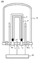
- FIGS. 1 to 3 are all schematic cross-sectional views showing a configuration example of a reactor for producing polycrystalline silicon according to the present invention.
- FIG. 4 is a diagram showing a conventional method for producing polycrystalline silicon in which a source gas is supplied only by a nozzle 3 to be described later. It is a schematic sectional drawing which shows the structural example of the reactor for water. In these drawings, the same reference numerals are assigned to the same components.
- the reactor 100 is sealed inside by a bottom plate 1 and a bell jar 10, and a silicon core wire 5 assembled in a torii form is disposed in the sealed space, and polycrystalline silicon 6 is deposited on the surface of the silicon core wire 5.
- a silicon rod is obtained.
- the bottom plate 1 has a core wire holder 8, a metal electrode 2, an insulator 7 and a bell jar 10 for controlling the surface temperature of the core wire to 900 to 1200 ° C. by applying an alternating current or a direct current from both ends of the torii type silicon core wire 5.
- Nozzles 3 and 3a for supplying the raw material gas inside and a reaction exhaust gas port 4 for discharging the reacted gas to the outside of the bell jar 10 are installed.
- Hydrogen gas and silicon source gas (generally trichlorosilane gas) are supplied from the source gas supply nozzles 3 and 3a.
- silicon core wires 5 is shown, but a plurality of pairs are generally arranged.
- FIG. 2 is provided with a nozzle 3 having a blower outlet above the upper surface of the bottom plate 1 and a blower outlet at a predetermined height with respect to the upper end of the core wire holder 8.
- the nozzle 3a is provided.
- the configuration shown in FIGS. 1 and 2 is different only in the arrangement position of the source gas supply nozzle 3a.
- the material is preferably ceramics that does not cause heavy metal contamination even at high temperatures, such as silicon nitride or carbon.
- silicon nitride containing no carbon source is a suitable nozzle material.
- control unit 9 controls the upper end of the core wire holder 8 to a predetermined height. It is good also as a structure provided with the nozzle 3a which can adjust the position of a blower outlet. In these drawings, three nozzles are shown, but the number of nozzles is not limited to three. In FIG. 3, the source gas supply system 20 is not shown.
- the first aspect of the reactor for producing polycrystalline silicon according to the present invention is a reactor 100 for producing polycrystalline silicon by the Siemens method, and a silicon core wire is attached to the bottom plate 1 of the reactor 100.
- At least one pair of core wire holders 8 for holding 5 and at least one nozzle 3a for supplying source gas are provided, and the gas blowing portion of the nozzle 3a has a predetermined height with respect to the upper end of the core wire holder 8. It has the structure provided.
- the second aspect of the reactor for producing polycrystalline silicon according to the present invention is a reactor 100 for producing polycrystalline silicon by the Siemens method, and a silicon core wire is attached to the bottom plate 1 of the reactor 100.
- At least one pair of core wire holders 8 for holding 5 and a nozzle 3a for supplying a raw material gas are provided, and the gas blowing portion of the nozzle 3a is set at a predetermined height with respect to the upper end of the core wire holder 8. It has the structure provided with the control part 9 adjusted to.
- the “predetermined height” (H) of the gas blowing portion of the source gas supply nozzle 3a is always a positive value (H> 0) in order to obtain a function described later.
- the length of the silicon core wire 5 in the vertical direction It is a value exceeding 1/3 of (height).
- the “predetermined height” is a value exceeding 50 cm, for example.
- the reactor for producing polycrystalline silicon according to the present invention is different from the conventional type in that the gas outlet is provided with the nozzle 3a whose "predetermined height" or position is adjusted.
- the reason why the gas blowing portion of the nozzle 3a is set to the “predetermined height” is due to the examination of the experimental results conducted by the present inventors.
- the region close to the average gas temperature in the furnace is at a height exceeding 50 cm with respect to the upper end of the core wire holder 8.
- the gas temperature in the reaction furnace increases due to radiation, and the metal chloride generated in the furnace is sublimated and gasified.
- the average gas temperature in the furnace at the end of the reaction process when the diameter of the silicon rod exceeds about 80 mm is 350 ° C. or more. Therefore, the gasified metal chloride causes the polycrystalline silicon to be contaminated with heavy metals.
- the diameter of the silicon rod becomes larger than about 80 mm in the reaction furnace, the flow of the gas in the upper part of the reaction furnace is deteriorated, and the tendency for the gas staying portion to be generated is increased. Further, since radiation between the silicon rods becomes remarkable, the temperature of the gas staying between the silicon rods is partially increased, and the thermal decomposition reaction in the region is actively promoted to generate silicon powder.
- silicon powder becomes significant when the concentration of chlorosilane in the feed gas increases.
- silicon powder is generated when the concentration of trichlorosilane in the feed gas becomes 25% or more.
- the nozzle 3a for supplying the raw material gas from the above-mentioned “predetermined height”, the region where the gas temperature is likely to rise such as the region near the center in the furnace or the upper region.
- the temperature distribution in the furnace is made uniform and the occurrence of heavy metal contamination and silicon powder caused by metal chlorides is suppressed without reducing productivity. To do.
- the gas composition supplied from the nozzle 3a is switched, and the gas supplied from the other nozzle 3 is trichlorosilane / hydrogen.
- a relatively low temperature gas having a different ratio is supplied from the nozzle 3a.
- the relatively low temperature gas supplied from the nozzle 3a is preferably a gas having a larger hydrogen ratio than the gas supplied from the nozzle 3 in order to suppress the supply of the silicon source, and only hydrogen gas. It may be.
- the temperature of the gas having a large hydrogen ratio is set to 100 ° C. or less, for example.
- the average gas temperature in the furnace is lowered and the gasification of the metal chloride is suppressed. Even if the diameter of the silicon rod is large, the gas sent to the upper region of the furnace promotes the downflow from the upper part of the furnace to the lower part, and the gas retention in the furnace is eliminated, resulting in local gas Temperature rise is less likely to occur, and generation of silicon powder is suppressed.
- the gas supply from the nozzle 3a as described above may be performed from the beginning of the precipitation reaction. However, if the supply of trichlorosilane to the upper region in the furnace is suppressed while the diameter of the silicon rod is small, the polycrystalline silicon is precipitated. The speed is reduced and productivity is worsened.
- Examples 1 and 2 and Comparative Examples 1 and 2 are shown below.
- a reactor having only one nozzle 3a at the center of the bottom plate as shown in FIG. 1 was used, and the gas blowing part of the nozzle 3a was a core wire.
- the holder was positioned at a height of 80 cm with respect to the upper end of the holder.
- Comparative Examples 1 and 2 as shown in FIG. 4, a reactor provided with only the nozzle 3 was used.
- Example 1 a raw material gas having a trichlorosilane concentration of 25% and a mixed gas of trichlorosilane gas and hydrogen gas (60 ° C.) at the initial stage of the precipitation reaction is supplied from the nozzle 3a.
- the supply was switched to supply of only hydrogen gas (60 ° C.), and an amount of hydrogen gas corresponding to 25% of the total hydrogen gas supplied into the furnace was supplied from the nozzle 3a.
- Example 2 a raw material gas having a trichlorosilane concentration of 25% and a mixed gas of trichlorosilane gas and hydrogen gas (60 ° C.) was supplied from the beginning to the end of the precipitation reaction.
- the gas supplied from the nozzle 3 in Comparative Example 1 and Comparative Example 2 is a mixed gas of trichlorosilane gas and hydrogen gas (60 ° C.), respectively, and is a raw material gas having a trichlorosilane concentration of 15% and 25%. .
- the reaction temperature is 1100 ° C.
- the final diameter of polycrystalline silicon is 120 mm ⁇
- the core wire length is 180 cm.
- the results are shown in Table 1.
- the “heavy metal concentration” in the table is a value obtained by measuring the total of six metals of Na, Cr, Fe, Ni, Cu, and Zn by ICP-MS.
- “In-furnace powder generation amount” and “surface protrusion generation” are the results of visually confirming the amount of silicon powder present on the bottom plate and the surface of the polycrystalline silicon rod after the reaction batch, respectively.
- the gas temperature in the furnace is made uniform, which is higher than that of the conventional structure. Generation of heavy metal contamination and silicon powder due to sublimation of objects is effectively suppressed.
Landscapes
- Chemical & Material Sciences (AREA)
- Organic Chemistry (AREA)
- Inorganic Chemistry (AREA)
- Silicon Compounds (AREA)
Abstract
底板1に、シリコン芯線5を保持する少なくとも一対の芯線ホルダ8と、原料ガスを供給するノズル3aが少なくとも1つ設けられており、このノズル3aのガス吹出部が、芯線ホルダ8の上端を基準として所定の高さに設けられている。例えば、多結晶シリコンの析出反応開始後、シリコン棒の径がおよそ80mmを超える程度になった時点で、ノズル3aから供給するガス組成の切り替えを行い、相対的に低い温度のガスをノズル3aから供給する。ガス温度が高くなり易くガス滞留も生じ易い領域を効率的に冷却することで、炉内の温度分布の均一化を図り、金属塩化物起因の重金属汚染やシリコン粉の発生を抑制する。
Description
本発明は多結晶シリコンの製造技術に関し、より詳細には、析出反応時に発生する金属塩化物やシリコン粉による金属汚染や形状異常を効果的に抑制する技術に関する。
多結晶シリコンは、半導体デバイス製造用の単結晶シリコン基板や太陽電池製造用基板の原料とされる。多結晶シリコンの製造方法としては、シーメンス法が知られている。シーメンス法は、クロロシランを含む原料ガスを加熱されたシリコン芯線に接触させ、これにより、該シリコン芯線の表面に多結晶シリコンをCVD法により気相成長させてシリコン棒として得る方法である。
シーメンス法により多結晶シリコンを気相成長する際、気相成長装置の反応炉内に、鉛直方向2本と水平方向1本のシリコン芯線を鳥居型に組み立てる。そして、この鳥居型のシリコン芯線の両端を、一対の芯線ホルダを介して反応炉底板上に配置した一対の金属電極に固定する。反応を起こさせる原料ガスの供給口及び反応排ガスの排気口も、この底板上に配置される。このような構成は、例えば、特公昭37-18861号公報(特許文献1)に開示されている。
一般に、反応炉内には、底板上に配置した一対の金属電極に固定された鳥居型のシリコン芯線が数十個設けられ、多重環式に配置される。また、底板には、原料ガス供給用のノズル及び反応ガスの排気口も適当数設けられるが、これらは炉内のガス流れが最適となるように配置される。このような底板の構成は、例えば、特開2002-241120号公報(特許文献2)、特開2006-206387号公報(特許文献3)、特開2009-107886号公報(特許文献4)に開示がされており、多結晶シリコン棒の水平断面方向の形状改善や表面での凸凹発生を抑制する手法についても言及されている。
シーメンス法により多結晶シリコンを析出させるには、シリコン芯線に電流を導通させ、シリコン芯線を900℃以上1200℃以下の温度範囲に加熱し、原料ガス(例えば、トリクロロシランと水素の混合ガス)を反応炉内に供給する。原料ガスの分解によりシリコン芯線上に多結晶シリコンが気相成長(析出)し、所望の直径の多結晶シリコン棒が逆U字状に形成される。通常は、シリコン芯線の反応炉内セットから多結晶シリコン棒の取出しまでがバッチ式に行われる。
ところで、クロロシランを原料ガスとして使用する場合、反応炉の構造材である金属とクロロシラン中の塩素分は反応し、反応炉内において金属塩化物が生成することが知られている。反応炉は1バッチ終了後に清掃されるが、一旦反応炉内に付着した金属塩化物は、この清掃においても完全には除去されず、反応炉内に微量の金属塩化物として残留することになる。
金属塩化物は、一般に、純金属よりも昇華温度が低くガス化し易い。このため、多結晶シリコンの析出反応中に炉内ガス温度が一定温度以上になると、炉内の残留金属塩化物が昇華してガス化してしまう。このガス化した金属塩化物は多結晶シリコン内に取り込まれるため、多結晶シリコンの重金属汚染の原因となる。特に、炉内ガス温度が350℃以上となると、上記現象が顕著となる。
また、炉内ガス温度が一定温度以上になると、シランガスの熱分解反応により粉状のシリコンが発生する。このシリコン粉が反応炉内を浮遊して炉内壁や底板に接触すると重金属が付着し、その状態で多結晶シリコン棒の表面に付着した場合には、多結晶シリコン棒を重金属汚染させたり表面に突起を発生させるなどして多結晶シリコンの品質を悪化させてしまう。
さらに、多結晶シリコン棒の表面温度を一定温度以上の高温に維持しつつ析出反応を継続させると、析出反応工程の後期に多結晶シリコン棒の径が大きくなってしまうことによる下記のような不都合も生じる。多結晶シリコンの生産性向上のためには、析出反応時の多結晶シリコン棒の表面温度をなるべく高くして反応速度を高めることが望ましい。一般に、析出反応時の多結晶シリコン棒の表面温度は900~1200℃程度であるが、このような比較的高温の状態で析出反応を継続してしまうと析出反応工程の後期に多結晶シリコン棒の径が大きくなってしまう。かかる温度にある表面積が増大すると、炉内での対流伝熱や輻射伝熱が顕著になり、これにより炉内にガス滞留域や局部的な温度上昇域が発生し、シリコン粉の発生を助長させる結果ともなる。逆に、金属塩化物起因の重金属汚染やシリコン粉の発生を抑制するために析出反応時の多結晶シリコン棒の表面温度を低くしてしまうと、析出速度は低下して生産性も低下してしまう。
上述したとおり、従来の多結晶シリコンの製造技術においては、多結晶シリコンの析出速度を高めて生産性向上を図ろうとすると、金属塩化物に起因する重金属汚染やシリコン粉の発生による品質の悪化が助長され、逆に、金属塩化物起因の重金属汚染やシリコン粉の発生を抑制しようとすると多結晶シリコンの生産性が低下せざるを得ないという問題があった。
本発明者らはこれまで、金属塩化物起因の重金属汚染やシリコン粉の発生を抑制するための幾つかの試みを行ってきた。具体的には、(i)炉内壁を冷却するための冷却水温度を低めにして炉内ガス温度を低下させる方法、(ii)多結晶シリコン棒の径の増大に伴って反応ガスの供給量を増やすことで多結晶シリコン棒の単位表面積当たりの原料ガス供給量を一定に保つ方法、(iii)反応温度を下げて析出させる方法、(iv)原料ガス中のシラン濃度を下げる方法などである。
しかし、上記(i)および(ii)の方法は製造設備に新たな機能を付加する必要があり、多結晶シリコンの製造コスト上昇を招く。また、上記(iii)および(iv)の方法も、多結晶シリコンの析出速度の低下などの理由により製造コスト上昇を招く。
本発明は、上述したような問題に鑑みてなされたものであって、その目的とするところは、生産性を低下させることなく、金属塩化物起因の重金属汚染やシリコン粉の発生を抑制し得る技術を提供することにある。
上述の課題を解決するために、本発明の多結晶シリコン製造用反応炉は、シーメンス法により多結晶シリコンを製造するための反応炉であって、該反応炉の底板には、シリコン芯線を保持する少なくとも一対の芯線ホルダと、原料ガスを供給する複数のノズルを備え、前記複数の原料ガス供給ノズルの一部のガス吹出部は前記芯線ホルダの上端を基準として所定の高さ(H>0)に設けられており、残りの原料ガス供給ノズルのガス吹出部は前記芯線ホルダの上端よりも下方に設けられていることを特徴とする。
また、本発明の他の態様の多結晶シリコン製造用反応炉は、シーメンス法により多結晶シリコンを製造するための反応炉であって、該反応炉の底板には、シリコン芯線を保持する少なくとも一対の芯線ホルダと、原料ガスを供給する複数のノズルを備え、前記複数の原料ガス供給ノズルのガス吹出部は前記芯線ホルダの上端よりも下方に設けられており、さらに、前記複数の原料ガス供給ノズルの一部のガス吹出部を前記芯線ホルダの上端を基準として所定の高さ(H>0)に調整する制御部を備えていることを特徴とする。
例えば、前記ガス吹出部の所定の高さは、前記シリコン芯線の垂直方向の長さの1/3を超える値、あるいは、前記芯線ホルダの上端を基準として50cmを超える値である。
本発明の多結晶シリコン製造用反応炉は、前記所定の高さにあるガス吹出部と他のガス吹出部に、トリクロロシラン/水素比の異なるガスを供給する原料ガス供給システムを備えている態様としてもよい。
好ましくは、前記原料ガス供給システムは、前記所定の高さにあるガス吹出部に、前記他のガス吹出部よりも水素比の大きなガスを供給する。
さらに好ましくは、前記原料ガス供給システムは、前記水素比の大きなガスを100℃以下の温度で供給する。
本発明の多結晶シリコンの製造方法は、上述の本発明の多結晶シリコン製造用反応炉を用い、炉内温度が均一になるように前記所定の高さを設定して多結晶シリコンを析出させる。
本発明が備える原料ガス供給用ノズルによれば、炉内ガス温度の局所的な上昇を抑制することができる。また、シリコン棒の径が大きくなっても炉内上部から下部へのダウンフローを促進できる。
このため、反応炉内の平均ガス温度が下がるだけでなく、炉内でのガス滞留が抑制され、熱分解によるシリコン粉の生成を抑制できる。
このように、本発明は、生産性を低下させることなく、金属塩化物起因の重金属汚染やシリコン粉の発生を抑制し得る多結晶シリコンの製造技術を提供する。
以下に、図面を参照して本発明の実施の形態について説明する。
図1~図3は何れも本発明の多結晶シリコン製造用反応炉の構成例を示す概略断面図で、図4は後述するノズル3のみで原料ガスを供給する、従来型の多結晶シリコン製造用反応炉の構成例を示す概略断面図である。なお、これらの図において、同一の構成要素には同じ符号を付した。
反応炉100は、底板1とベルジャ10により内部が密閉され、当該密閉空間内に鳥居型に組んだシリコン芯線5を配置させてこのシリコン芯線5の表面に多結晶シリコン6を析出させて多結晶シリコン棒が得られる。底板1には、鳥居型シリコン芯線5の両端から交流又は直流電流を通電させて芯線表面温度を900~1200℃に制御するための芯線ホルダ8、金属電極2、及び絶縁物7と、ベルジャ10内部に原料ガスを供給するためのノズル3および3aと、反応後のガスをベルジャ10外部に排出するための反応排ガス口4が設置されている。原料ガス供給ノズル3,3aからは、水素ガスとシリコン原料ガス(一般にはトリクロルシランガス)が供給される。なお、図中には、シリコン芯線5は一対のみ図示されているが、一般には複数対が配置される。
ノズル3、3aのガス吹出口からは、原料ガス供給システム20により、流速・流量が制御された原料ガスが供給される。図1および図2に示した態様の反応炉100は、底板1の上面近傍の上方に吹出口を有するノズル3のほか、芯線ホルダ8の上端を基準として所定の高さに吹出口が設けられているノズル3aを備えている。図1と図2に示した態様は、原料ガス供給ノズル3aの配置位置においてのみ構成が相違している。
ノズル3,3aは高温の反応炉内に設置されるから、その材質は高温下でも重金属汚染を発生させないセラミックス、例えば、窒化珪素やカーボンが望ましい。特に、炭素源を含まない窒化珪素は好適なノズル材料である。
なお、図3に示した態様の反応炉100のように、底板1の上面近傍の上方に吹出口を有するノズル3のほか、制御部9により芯線ホルダ8の上端を基準として所定の高さに吹出口の位置調整が可能なノズル3aを備えている構成としてもよい。また、これらの図中には3つのノズルが図示されているが、ノズル数は3に限定されるものではない。図3では、原料ガス供給システム20の図示は省略した。
つまり、本発明に係る多結晶シリコン製造用反応炉の第1の態様のものは、シーメンス法により多結晶シリコンを製造するための反応炉100であって、反応炉100の底板1に、シリコン芯線5を保持する少なくとも一対の芯線ホルダ8と、原料ガスを供給するノズル3aが少なくとも1つ設けられており、このノズル3aのガス吹出部が、芯線ホルダ8の上端を基準として所定の高さに設けられている構成を有している。
また、本発明に係る多結晶シリコン製造用反応炉の第2の態様のものは、シーメンス法により多結晶シリコンを製造するための反応炉100であって、反応炉100の底板1に、シリコン芯線5を保持する少なくとも一対の芯線ホルダ8と、原料ガスを供給するノズル3aが少なくとも1つ設けられており、さらに、上記ノズル3aのガス吹出部を芯線ホルダ8の上端を基準として所定の高さに調整する制御部9を備える構成を有している。
上記原料ガス供給ノズル3aのガス吹出部の「所定の高さ」(H)は後述の機能を得るため必ず正の値(H>0)であり、例えば、シリコン芯線5の垂直方向の長さ(高さ)の1/3を超える値である。また、この「所定の高さ」は、例えば、50cmを超える値である。
つまり、本発明の多結晶シリコン製造用反応炉は、ガス吹出口が上記「所定の高さ」にある乃至は位置調整されるノズル3aを備えている点において従来型のものと相違する。なお、本発明においてノズル3aのガス吹出部を上記「所定の高さ」としたのは、本発明者らが行った実験結果の検討によるものである。例えば、本発明者らの行った実験によれば、一般的な反応炉の場合、炉内の平均ガス温度に近くなる領域は、芯線ホルダ8の上端を基準として50cmを越える高さにある。
既に説明したように、シリコン芯線5に多結晶シリコン6が析出してシリコン棒の径が大きくなると、シリコン棒相互間の輻射が顕著になる。反応炉内のガス温度は輻射により高まり、炉内で生成した金属塩化物が昇華してガス化する。特に、シリコン棒の最終直径として120mm程度を想定して設計されている反応炉において、反応工程終盤となりシリコン棒の直径がおよそ80mmを超えた環境下の炉内の平均ガス温度は350℃以上ともなるため、ガス化した金属塩化物が多結晶シリコンを重金属汚染させる原因となる。
加えて、上記反応炉内でシリコン棒の直径がおよそ80mmを超える程度に大きくなると反応炉上部ガスの流れが悪くなり、ガスの滞留部が発生する傾向が大きくなる。さらに、シリコン棒間の輻射も顕著になるから、シリコン棒間に滞留するガスの温度が部分的に高まって当該領域での熱分解反応が盛んになってシリコン粉の発生が助長される。
なお、本発明者らの検討によれば、シリコン粉の発生は供給原料ガス中のクロロシラン濃度が高まると顕著となる。トリクロロシランを原料ガスとした場合、供給原料ガス中のトリクロロシランの濃度が25%以上になるとシリコン粉の発生が起こる。
本発明では、上述の「所定の高さ」にある吹出口から原料ガスを供給するノズル3aを設けることで、炉内の中心に近い領域や上部領域のようなガス温度の上昇が起こり易い領域に、相対的に低い温度のガスを効率的に供給することで、炉内の温度分布の均一化を図り、生産性を低下させることなく金属塩化物起因の重金属汚染やシリコン粉の発生を抑制する。
例えば、多結晶シリコンの析出反応開始後、シリコン棒の径が80mmを超えた時点で、ノズル3aから供給するガス組成の切り替えを行い、他のノズル3から供給されるガスとはトリクロロシラン/水素比の異なる相対的に低い温度のガスをノズル3aから供給する。本発明者らの検討によれば、上述した「所定の高さ」から上方の炉内領域はガス温度が高くなり易くガス滞留も生じ易いため、金属塩化物起因の重金属汚染やシリコン粉の発生が起こり易い領域であるが、かかる領域を効率的に冷却することで、炉内の温度分布の均一化を図るのである。
ここで、ノズル3aから供給される相対的に低い温度のガスは、シリコン源の供給を抑える意味で、ノズル3から供給されるガスよりも水素比の大きなガスであることが好ましく、水素ガスのみであってもよい。また、当該水素比の大きなガスの温度は、例えば100℃以下とする。
このようなガス供給を行うと、炉内でガス温度が高くなる領域の反応ガス中のシリコン濃度が相対的に低下し、熱分解反応によるシリコン粉の発生が抑制される。
ノズル3aから供給するガス組成の切り替えに伴い、他のノズル3から供給するガス中のトリクロロシラン濃度も切り替えることが好ましい。これは、ガス組成の切り替えによりノズル3aから炉内に供給されるシリコン源が抑えられるため、その分を補うシリコン源を他のノズル3から供給するためである。
このような原料ガス供給を行うと、炉内での平均ガス温度は下がり、金属塩化物のガス化が抑制される。また、シリコン棒の径が大きくなっていても、炉内上部領域に送り込まれたガスは炉内上部から下部へのダウンフローを促進し、炉内でのガス滞留が解消されて局所的なガス温度上昇も発生し難くなり、シリコン粉の発生も抑制される。
上述したようなノズル3aからのガス供給は析出反応の最初から行ってもよいが、シリコン棒の径が細いうちから炉内上部領域へのトリクロロシラン供給を抑えてしまうと、多結晶シリコンの析出速度が低下して生産性は悪くなる。
以下に、実施例1及び2と比較例1及び2の結果を示す。なお、これらの多結晶シリコンの製造において、実施例1及び2では、図1に示したような、ノズル3aを底板中央に1本だけ設けた反応炉を用い、ノズル3aのガス吹出部を芯線ホルダの上端を基準として80cmの高さに位置させた。一方、比較例1及び2では、図4に示したように、ノズル3のみを設けた反応炉を用いた。
実施例1では、ノズル3aから、析出反応初期はトリクロロシランガスと水素ガス(60℃)の混合ガスであってトリクロロシランの濃度が25%の原料ガスを供給し、多結晶シリコン棒の径が概ね80mmとなった時点で水素ガス(60℃)のみの供給に切り替え、当該ノズル3aから、炉内に供給する全水素ガスの25%に相当する量の水素ガスを供給した。
また、実施例2では、析出反応初期から終了まで、トリクロロシランガスと水素ガス(60℃)の混合ガスであってトリクロロシランの濃度が25%の原料ガスを供給した。
一方、比較例1および比較例2でノズル3から供給したガスは、それぞれ、トリクロロシランガスと水素ガス(60℃)の混合ガスであってトリクロロシランの濃度が15%および25%の原料ガスである。
これら実施例1、2および比較例1、2の反応温度は1100℃、多結晶シリコンの最終径は120mmφ、芯線長さは180cmである。
結果を表1に示す。なお、当該表中の「重金属濃度」は、Na、Cr、Fe、Ni、Cu、Znの6種の金属の総計をICP-MSにより測定した値である。また、「炉内粉発生量」および「表面突起発生」は、それぞれ、反応バッチ終了後に底板上に存在したシリコン粉の量および多結晶シリコン棒の表面を目視にて確認した結果である。

比較例2のものは、炉内粉発生および表面突起発生の何れもが認められており、多結晶シリコン中の重金属も高い値にある。また、比較例1のものは、炉内粉発生および表面突起発生の何れも認められないが、多結晶シリコン中の重金属が十分に低いとは言えない。
これに対し、実施例1および実施例2のものは、何れも、炉内粉発生および表面突起発生の何れが認められないことに加え、多結晶シリコン中の重金属も十分に低い値となっている。
以上説明したように、本発明に係る反応炉によれば、多結晶シリコンの径が大きくなっても、炉内ガス温度の均一化が図られ、従来の構造のものに比較して、金属塩化物の昇華に起因する重金属汚染やシリコン粉の発生が効果的に抑制される。
本発明によれば、生産性を低下させることなく、金属塩化物起因の重金属汚染やシリコン粉の発生を抑制し得る多結晶シリコンの製造技術が提供される。
1 底板
2 金属電極
3、3a 原料ガス供給ノズル
4 反応排ガス口
5 シリコン芯線
6 多結晶シリコン
7 絶縁物
8 芯線ホルダ
9 ノズルの吹出口位置の制御部
10 ベルジャ
20 原料ガス供給システム
100 反応炉
2 金属電極
3、3a 原料ガス供給ノズル
4 反応排ガス口
5 シリコン芯線
6 多結晶シリコン
7 絶縁物
8 芯線ホルダ
9 ノズルの吹出口位置の制御部
10 ベルジャ
20 原料ガス供給システム
100 反応炉
Claims (8)
- シーメンス法により多結晶シリコンを製造するための反応炉であって、
該反応炉の底板には、シリコン芯線を保持する少なくとも一対の芯線ホルダと、原料ガスを供給する複数のノズルを備え、
前記複数の原料ガス供給ノズルの一部のガス吹出部は前記芯線ホルダの上端を基準として所定の高さ(H>0)に設けられており、残りの原料ガス供給ノズルのガス吹出部は前記芯線ホルダの上端よりも下方に設けられていることを特徴とする多結晶シリコン製造用反応炉。 - シーメンス法により多結晶シリコンを製造するための反応炉であって、
該反応炉の底板には、シリコン芯線を保持する少なくとも一対の芯線ホルダと、原料ガスを供給する複数のノズルを備え、
前記複数の原料ガス供給ノズルのガス吹出部は前記芯線ホルダの上端よりも下方に設けられており、さらに、
前記複数の原料ガス供給ノズルの一部のガス吹出部を前記芯線ホルダの上端を基準として所定の高さ(H>0)に調整する制御部を備えていることを特徴とする多結晶シリコン製造用反応炉。 - 前記ガス吹出部の所定の高さは前記シリコン芯線の垂直方向の長さの1/3を超える値である、請求項1又は2に記載の多結晶シリコン製造用反応炉。
- 前記ガス吹出部の所定の高さは50cmを超える値である、請求項1又は2に記載の多結晶シリコン製造用反応炉。
- 前記所定の高さにあるガス吹出部と他のガス吹出部に、トリクロロシラン/水素比の異なるガスを供給する原料ガス供給システムを備えている、請求項1又は2に記載の多結晶シリコン製造用反応炉。
- 前記原料ガス供給システムは、前記所定の高さにあるガス吹出部に、前記他のガス吹出部よりも水素比の大きなガスを供給する、請求項5に記載の多結晶シリコン製造用反応炉。
- 前記原料ガス供給システムは、前記水素比の大きなガスを100℃以下の温度で供給する、請求項6に記載の多結晶シリコン製造用反応炉。
- 請求項1又は2に記載の多結晶シリコン製造用反応炉を用い、炉内温度が均一になるように前記所定の高さを設定して多結晶シリコンを析出させる、多結晶シリコンの製造方法。
Applications Claiming Priority (2)
| Application Number | Priority Date | Filing Date | Title |
|---|---|---|---|
| JP2011-011744 | 2011-01-24 | ||
| JP2011011744A JP5579634B2 (ja) | 2011-01-24 | 2011-01-24 | 多結晶シリコン製造用反応炉および多結晶シリコンの製造方法 |
Publications (1)
| Publication Number | Publication Date |
|---|---|
| WO2012101969A1 true WO2012101969A1 (ja) | 2012-08-02 |
Family
ID=46580549
Family Applications (1)
| Application Number | Title | Priority Date | Filing Date |
|---|---|---|---|
| PCT/JP2012/000157 Ceased WO2012101969A1 (ja) | 2011-01-24 | 2012-01-12 | 多結晶シリコン製造用反応炉および多結晶シリコンの製造方法 |
Country Status (2)
| Country | Link |
|---|---|
| JP (1) | JP5579634B2 (ja) |
| WO (1) | WO2012101969A1 (ja) |
Cited By (2)
| Publication number | Priority date | Publication date | Assignee | Title |
|---|---|---|---|---|
| CN111206279A (zh) * | 2020-02-26 | 2020-05-29 | 江苏鑫华半导体材料科技有限公司 | 制备低内应力区熔用电子级多晶硅的系统和方法 |
| CN114206777A (zh) * | 2019-08-23 | 2022-03-18 | 株式会社德山 | 多晶硅棒及其制造方法 |
Families Citing this family (3)
| Publication number | Priority date | Publication date | Assignee | Title |
|---|---|---|---|---|
| JP5886234B2 (ja) | 2013-04-11 | 2016-03-16 | 信越化学工業株式会社 | シラン化合物またはクロロシラン化合物の精製方法、多結晶シリコンの製造方法、および、弱塩基性イオン交換樹脂の再生処理方法 |
| JP6069167B2 (ja) | 2013-10-23 | 2017-02-01 | 信越化学工業株式会社 | 多結晶シリコンの製造方法 |
| KR101895526B1 (ko) * | 2015-08-28 | 2018-09-05 | 한화케미칼 주식회사 | 폴리실리콘 제조 장치 |
Citations (3)
| Publication number | Priority date | Publication date | Assignee | Title |
|---|---|---|---|---|
| JPH026317A (ja) * | 1988-01-15 | 1990-01-10 | Union Carbide Corp | シランの熱分解により一様に大径の多結晶棒を形成するための反応器系および方法 |
| JP2009149495A (ja) * | 2007-11-28 | 2009-07-09 | Mitsubishi Materials Corp | 多結晶シリコン製造装置及び製造方法 |
| WO2009128886A1 (en) * | 2008-04-14 | 2009-10-22 | Hemlock Semiconductor Corporation | Manufacturing apparatus for depositing a material and an electrode for use therein |
-
2011
- 2011-01-24 JP JP2011011744A patent/JP5579634B2/ja active Active
-
2012
- 2012-01-12 WO PCT/JP2012/000157 patent/WO2012101969A1/ja not_active Ceased
Patent Citations (3)
| Publication number | Priority date | Publication date | Assignee | Title |
|---|---|---|---|---|
| JPH026317A (ja) * | 1988-01-15 | 1990-01-10 | Union Carbide Corp | シランの熱分解により一様に大径の多結晶棒を形成するための反応器系および方法 |
| JP2009149495A (ja) * | 2007-11-28 | 2009-07-09 | Mitsubishi Materials Corp | 多結晶シリコン製造装置及び製造方法 |
| WO2009128886A1 (en) * | 2008-04-14 | 2009-10-22 | Hemlock Semiconductor Corporation | Manufacturing apparatus for depositing a material and an electrode for use therein |
Cited By (3)
| Publication number | Priority date | Publication date | Assignee | Title |
|---|---|---|---|---|
| CN114206777A (zh) * | 2019-08-23 | 2022-03-18 | 株式会社德山 | 多晶硅棒及其制造方法 |
| CN111206279A (zh) * | 2020-02-26 | 2020-05-29 | 江苏鑫华半导体材料科技有限公司 | 制备低内应力区熔用电子级多晶硅的系统和方法 |
| CN111206279B (zh) * | 2020-02-26 | 2023-09-22 | 江苏鑫华半导体科技股份有限公司 | 制备低内应力区熔用电子级多晶硅的系统和方法 |
Also Published As
| Publication number | Publication date |
|---|---|
| JP5579634B2 (ja) | 2014-08-27 |
| JP2012153547A (ja) | 2012-08-16 |
Similar Documents
| Publication | Publication Date | Title |
|---|---|---|
| CN103098173A (zh) | 多晶硅生产 | |
| KR101577452B1 (ko) | 다결정 실리콘 반응로 | |
| US7105053B2 (en) | Energy efficient method for growing polycrystalline silicon | |
| KR101821851B1 (ko) | 다결정 실리콘의 제조 방법 및 다결정 실리콘 제조용 반응로 | |
| EP2489634B1 (en) | Core wire holder for producing polycrystalline silicon and method for producing polycrystalline silicon | |
| US10870581B2 (en) | Reaction furnace for producing polycrystalline silicon, apparatus for producing polycrystalline silicon, method for producing polycrystalline silicon, and polycrystalline silicon rod or polycrystalline silicon ingot | |
| JP5579634B2 (ja) | 多結晶シリコン製造用反応炉および多結晶シリコンの製造方法 | |
| JP2014141748A (ja) | Cvdリアクタ、大面積シリコンフィラメント、及び、ポリシリコンの生産方法 | |
| JPWO2012067112A1 (ja) | エピタキシャル炭化珪素単結晶基板の製造方法 | |
| KR101279414B1 (ko) | 폴리실리콘 제조장치 및 폴리실리콘 제조방법 | |
| JP6046269B2 (ja) | 多結晶シリコンを堆積させる方法 | |
| US11519069B2 (en) | Polycrystalline silicon manufacturing apparatus | |
| JPH0317771B2 (ja) | ||
| JP5820917B2 (ja) | 多結晶シリコンの製造方法 | |
| WO2014054260A1 (ja) | 多結晶シリコン製造装置 | |
| JP2012224499A (ja) | シリコン芯線の製造方法 | |
| JP5917359B2 (ja) | 多結晶シリコン製造用原料ガスの供給方法および多結晶シリコン | |
| WO2011074176A1 (ja) | シリコンエピタキシャルウェーハの製造方法 | |
| JP7591987B2 (ja) | 多結晶シリコンロッドの製造装置及び製造方法 | |
| KR101755764B1 (ko) | 폴리실리콘의 제조 장치 및 이를 이용한 폴리실리콘 제조방법 | |
| JP5393185B2 (ja) | シリコン製造に用いるカーボンヒータの再生方法 |
Legal Events
| Date | Code | Title | Description |
|---|---|---|---|
| 121 | Ep: the epo has been informed by wipo that ep was designated in this application |
Ref document number: 12738901 Country of ref document: EP Kind code of ref document: A1 |
|
| NENP | Non-entry into the national phase |
Ref country code: DE |
|
| 122 | Ep: pct application non-entry in european phase |
Ref document number: 12738901 Country of ref document: EP Kind code of ref document: A1 |