WO2012101888A1 - 医療機器 - Google Patents
医療機器 Download PDFInfo
- Publication number
- WO2012101888A1 WO2012101888A1 PCT/JP2011/075686 JP2011075686W WO2012101888A1 WO 2012101888 A1 WO2012101888 A1 WO 2012101888A1 JP 2011075686 W JP2011075686 W JP 2011075686W WO 2012101888 A1 WO2012101888 A1 WO 2012101888A1
- Authority
- WO
- WIPO (PCT)
- Prior art keywords
- image
- medical device
- tip
- superimposed
- distal end
- Prior art date
Links
Images


Classifications
-
- A—HUMAN NECESSITIES
- A61—MEDICAL OR VETERINARY SCIENCE; HYGIENE
- A61B—DIAGNOSIS; SURGERY; IDENTIFICATION
- A61B1/00—Instruments for performing medical examinations of the interior of cavities or tubes of the body by visual or photographical inspection, e.g. endoscopes; Illuminating arrangements therefor
- A61B1/00002—Operational features of endoscopes
- A61B1/00043—Operational features of endoscopes provided with output arrangements
- A61B1/00045—Display arrangement
- A61B1/0005—Display arrangement combining images e.g. side-by-side, superimposed or tiled
-
- A—HUMAN NECESSITIES
- A61—MEDICAL OR VETERINARY SCIENCE; HYGIENE
- A61B—DIAGNOSIS; SURGERY; IDENTIFICATION
- A61B34/00—Computer-aided surgery; Manipulators or robots specially adapted for use in surgery
- A61B34/20—Surgical navigation systems; Devices for tracking or guiding surgical instruments, e.g. for frameless stereotaxis
- A61B2034/2046—Tracking techniques
- A61B2034/2051—Electromagnetic tracking systems
-
- A—HUMAN NECESSITIES
- A61—MEDICAL OR VETERINARY SCIENCE; HYGIENE
- A61B—DIAGNOSIS; SURGERY; IDENTIFICATION
- A61B90/00—Instruments, implements or accessories specially adapted for surgery or diagnosis and not covered by any of the groups A61B1/00 - A61B50/00, e.g. for luxation treatment or for protecting wound edges
- A61B90/36—Image-producing devices or illumination devices not otherwise provided for
- A61B2090/364—Correlation of different images or relation of image positions in respect to the body
- A61B2090/365—Correlation of different images or relation of image positions in respect to the body augmented reality, i.e. correlating a live optical image with another image
-
- A—HUMAN NECESSITIES
- A61—MEDICAL OR VETERINARY SCIENCE; HYGIENE
- A61B—DIAGNOSIS; SURGERY; IDENTIFICATION
- A61B90/00—Instruments, implements or accessories specially adapted for surgery or diagnosis and not covered by any of the groups A61B1/00 - A61B50/00, e.g. for luxation treatment or for protecting wound edges
- A61B90/36—Image-producing devices or illumination devices not otherwise provided for
- A61B90/37—Surgical systems with images on a monitor during operation
- A61B2090/378—Surgical systems with images on a monitor during operation using ultrasound
-
- A—HUMAN NECESSITIES
- A61—MEDICAL OR VETERINARY SCIENCE; HYGIENE
- A61B—DIAGNOSIS; SURGERY; IDENTIFICATION
- A61B34/00—Computer-aided surgery; Manipulators or robots specially adapted for use in surgery
- A61B34/25—User interfaces for surgical systems
-
- A—HUMAN NECESSITIES
- A61—MEDICAL OR VETERINARY SCIENCE; HYGIENE
- A61B—DIAGNOSIS; SURGERY; IDENTIFICATION
- A61B6/00—Apparatus for radiation diagnosis, e.g. combined with radiation therapy equipment
- A61B6/02—Devices for diagnosis sequentially in different planes; Stereoscopic radiation diagnosis
- A61B6/03—Computerised tomographs
- A61B6/032—Transmission computed tomography [CT]
-
- A—HUMAN NECESSITIES
- A61—MEDICAL OR VETERINARY SCIENCE; HYGIENE
- A61B—DIAGNOSIS; SURGERY; IDENTIFICATION
- A61B6/00—Apparatus for radiation diagnosis, e.g. combined with radiation therapy equipment
- A61B6/46—Apparatus for radiation diagnosis, e.g. combined with radiation therapy equipment with special arrangements for interfacing with the operator or the patient
- A61B6/461—Displaying means of special interest
- A61B6/466—Displaying means of special interest adapted to display 3D data
-
- A—HUMAN NECESSITIES
- A61—MEDICAL OR VETERINARY SCIENCE; HYGIENE
- A61B—DIAGNOSIS; SURGERY; IDENTIFICATION
- A61B8/00—Diagnosis using ultrasonic, sonic or infrasonic waves
- A61B8/52—Devices using data or image processing specially adapted for diagnosis using ultrasonic, sonic or infrasonic waves
- A61B8/5215—Devices using data or image processing specially adapted for diagnosis using ultrasonic, sonic or infrasonic waves involving processing of medical diagnostic data
- A61B8/523—Devices using data or image processing specially adapted for diagnosis using ultrasonic, sonic or infrasonic waves involving processing of medical diagnostic data for generating planar views from image data in a user selectable plane not corresponding to the acquisition plane
-
- A—HUMAN NECESSITIES
- A61—MEDICAL OR VETERINARY SCIENCE; HYGIENE
- A61B—DIAGNOSIS; SURGERY; IDENTIFICATION
- A61B8/00—Diagnosis using ultrasonic, sonic or infrasonic waves
- A61B8/52—Devices using data or image processing specially adapted for diagnosis using ultrasonic, sonic or infrasonic waves
- A61B8/5215—Devices using data or image processing specially adapted for diagnosis using ultrasonic, sonic or infrasonic waves involving processing of medical diagnostic data
- A61B8/5238—Devices using data or image processing specially adapted for diagnosis using ultrasonic, sonic or infrasonic waves involving processing of medical diagnostic data for combining image data of patient, e.g. merging several images from different acquisition modes into one image
- A61B8/5261—Devices using data or image processing specially adapted for diagnosis using ultrasonic, sonic or infrasonic waves involving processing of medical diagnostic data for combining image data of patient, e.g. merging several images from different acquisition modes into one image combining images from different diagnostic modalities, e.g. ultrasound and X-ray
Definitions
- Embodiments of the present invention relate to a medical device that is inserted into a lumen of a subject, and more particularly, to a medical device that performs highly accurate examination / treatment based on three-dimensional image data of a subject.
- diagnosis using three-dimensional images has been widely performed. For example, by capturing a tomographic image of a subject with an X-ray CT (Computed Tomography) apparatus, three-dimensional image data in the subject is obtained, and a target region is diagnosed using the three-dimensional image data. It has become.
- X-ray CT Computed Tomography
- the subject is continuously moved while continuously rotating the X-ray irradiation position and the detection position, thereby subjecting the subject to a helical continuous scan (helical scan). Then, a three-dimensional image is formed from a large number of two-dimensional tomographic images of consecutive subjects.
- One of the three-dimensional images used for diagnosis is a three-dimensional image of the lung bronchus.
- the three-dimensional image of the bronchus is used to three-dimensionally grasp the position of an abnormal part suspected of lung cancer, for example.
- a bronchoscope is inserted and a biopsy needle or biopsy forceps is protruded from the distal end of the insertion part to collect a tissue sample.
- Japanese Laid-Open Patent Publication No. 2004-180940 and Japanese Laid-Open Patent Publication No. 2005-131042 disclose a three-dimensional image of a duct in the subject based on three-dimensional image data of the subject.
- Japanese Patent Application Laid-Open No. 2003-265408 discloses an endoscope guidance device that superimposes and displays the position of the distal end portion of an endoscope on a tomographic image.
- the known insertion navigation system may not be able to easily insert the distal end of the insertion portion to the target site.
- Embodiment of this invention aims at providing the medical device which is easy to insert the front-end
- a medical device includes an insertion unit that is inserted into a lumen of a subject, a storage unit that stores three-dimensional image data of the subject acquired in advance, and the insertion unit within the lumen
- Position calculation means for calculating the position and direction of the distal end portion of the limb, and path generation means for generating an insertion path for inserting the distal end portion to the target position via the lumen based on the three-dimensional image
- a tomographic image generating means for generating a tomographic image based on the position and direction of the tip from the three-dimensional image data
- a superimposed image generating means for generating a superimposed image by superimposing the insertion path and the tomographic image
- Display means for displaying the superimposed image.
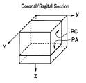
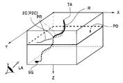
- FIG. 1 is a three-dimensional model diagram showing a state where the insertion portion 2A is being inserted toward the target site 9G.
- the insertion portion 2A has a channel 8 that passes through the inside thereof, and the treatment tool 6 inserted from the channel insertion port 8A protrudes from the distal end portion 2C to perform a biopsy of the target site 9G.
- the Z-axis direction is the body axis of the subject 7
- the X-axis direction is the left-right direction of the subject 7
- the Y-axis direction is the front-rear direction of the subject 7.
- a superimposed image PW1 which is a three-dimensional model image showing a three-dimensional space in which R and N are superimposed and displayed, is displayed on the display unit 4 (see FIG. 2).
- the operator can arbitrarily set the line of sight LA (viewpoint position, line of sight direction, line of sight rotation angle) of the three-dimensional model diagram.
- the tomographic image PO displayed is automatically updated as the position of the tip 2C changes, that is, as the insertion operation proceeds.
- a position display mark P2C indicating the position of the distal end portion 2C of the insertion portion 2A is superimposed on the tomographic image PO.
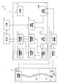
- the medical device 1 includes an endoscope apparatus 2, a main body unit 3 for performing insertion support, a display unit 4 that is a display unit, and an input unit 5 that is an input unit.
- the endoscopic apparatus 2 includes a bronchus having an insertion unit 2A that is an insertion unit in which an imaging unit 2B that is an imaging unit is disposed at a distal end portion 2C, and an endoscope control unit 2D that controls the insertion unit 2A and the like. It is a mirror.
- a channel 8 into which the treatment tool 6 can be inserted is disposed inside the insertion portion 2A.
- the main body unit 3 includes an endoscope image processing unit 11, a superimposed image generating unit 12 that is a superimposed image generating unit, a position calculating unit 20 that is a position calculating unit, and a virtual endoscopic image (Virtual Bronchus Scope image: hereinafter , Also referred to as a “VBS image”.)
- the control unit 10 controls the entire navigation.
- the endoscopic image processing unit 11 processes an image captured by the imaging unit 2B and outputs an endoscopic image (hereinafter also referred to as “real image”).
- the CT image data storage unit 15 stores three-dimensional image data of the subject 7 as a subject acquired in advance using a CT apparatus.
- the VBS image generation unit 13 generates a VBS image using the position, direction, and rotation angle (hereinafter also referred to as “position etc.”) of the distal end portion 2C as line-of-sight parameters from the three-dimensional image data.
- the position calculation unit 20 calculates the position and the like of the distal end portion 2C of the insertion portion 2A inserted into the bronchus 9.
- the core line calculation unit 16 calculates the core line S of the bronchi 9 from the three-dimensional image data.
- the core line S is a line connecting the barycentric points of the vertical direction of the bronchus 9, that is, information on the longitudinal direction of the lumen.
- information such as a center line that connects the center points of the vertical planes of the lumen in the duct direction may be used.
- the path generation unit 18 generates an insertion path R along the core line S from the three-dimensional image data to the target site 9G that is the target position set by the operator via the input unit 5.
- the tomographic image generation unit 14 generates a tomographic image PO that includes the three-dimensional position of the tip 2C calculated by the position calculator 20 and is perpendicular to the direction of the tip 2C from the three-dimensional image data.
- the superimposed image generation unit 12 is a superimposition that is a three-dimensional model image when a three-dimensional space in which the three-dimensional insertion path R and the tomographic image PO generated by the tomographic image generation unit 14 are superimposed is observed from a predetermined line of sight LA. An image PW1 is generated.
- the display unit 4 displays a navigation image having at least one of a real image and a VBS image and a superimposed image PW1 during the insertion operation.
- main body 3 do not have to be independent hardware, and may be programs that are read and operated by a CPU, for example.
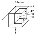
- the tomographic image generated by the tomographic image generation unit 14 will be described with reference to FIGS. 3A to 3F.
- the axial image PA shown in FIG. 3A is an image on the XY plane perpendicular to the body axis of the subject 7, and the coronal image PC shown in FIG. 3B is an image on the XZ plane facing the subject 7, FIG.
- the sagittal image PS shown in FIG. 3 is an image of the YZ plane in the side surface direction of the subject 7.
- the oblique image PO shown in FIG. 3D is an image of an arbitrary plane.
- the composite tomographic image shown in FIG. 3E is composed of two orthogonal planes PA and PC.
- the combined tomographic image including two orthogonal planes may be a combination of images of other planes. Further, it may be a composite tomographic image composed of the oblique image PO and an orthogonal plane image.
- the composite tomographic image shown in FIG. 3F is an example of a composite tomographic image including three orthogonal planes.
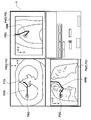
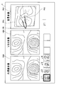
- ⁇ Setting operation mode >> First, the target position setting screen shown in FIG. An axial image PA, a coronal image PC, and a sagittal image PS are displayed on the target position setting screen.
- the target part 9G is set using the target position setting screen displayed on the display unit 4.
- the target position mark P9G indicating the target position is superimposed on the axial image PA, the coronal image PC, and the sagittal image PS displayed on the target position setting screen.
- the start position mark P7A indicating the position of the pharynx 7A, which is the insertion start position is within the display range of the axial image PA, but the display range of the coronal image PC and the sagittal image PS. Is outside.
- the target position mark P9G displayed on the other tomographic image also moves accordingly.
- the insertion start position may also be set by moving the start position mark P7A.
- the target position does not need to be a point and may be a target area having a predetermined volume. Further, in order to set the target position more accurately, the tomographic image may be enlarged and displayed.
- the path generation unit 18 calculates the insertion path R from the pharynx 7A, which is the insertion start position, to the target site 9G, which is the target position, by the CT image data storage unit. 15 is generated from the three-dimensional image data stored in 15.
- the insertion path R is a core line connected to the target site 9G among the core lines S connecting the center of gravity or the center point of the lumen cross section of the three-dimensional image data.
- the route generation unit 18 may generate a plurality of insertion routes and prompt the operator to select. That is, when the target site 9G exists between a plurality of lumens, or when the target site 9G is a site having a predetermined volume or more, a plurality of insertion paths are calculated.
- a superimposed image PW2 in which a path image PPR indicating the insertion path R is superimposed on each tomographic image is displayed.
- the path image PPR is an image obtained by projecting the three-dimensional insertion path R onto the plane of each tomographic image.
- the VBS image generation unit 13 generates the VBS images of the branch units J1 to J4 in the insertion path R and the thumbnail images that are reduced images of the respective VBS images.
- FIG. 7 is an example of a navigation screen when the distal end portion 2C is at the first branch portion J1 of the four branch portions.
- the thumbnail image reduced images of the four branch portions J1 to J4 are displayed, and the branch portion number J1 is displayed larger.
- the position calculator 20 calculates the position and the like of the tip 2C in real time or at predetermined time intervals.
- the position calculation unit 20 controls the VBS image generation unit 13 to generate a VBS image similar to the real image captured by the CCD (2B). That is, the VBS image generation unit 13 generates a VBS image having the line-of-sight parameter as the position, direction, and rotation angle (X1, Y1, Z1, a1, e1, r1).
- (X, Y, Z) is a three-dimensional coordinate value
- (a) is an azimuth angle (azimuth angle)
- e) is an elevation angle (elevation angle)
- (r) is a rotation angle (roll angle).
- the position calculation unit 20 compares the similarity between the VBS image and the real image.
- the similarity between images is performed by known image processing, and either matching at the pixel data level or matching at the level of the feature extracted from the image may be used.
- the actual comparison process is performed based on the similarity between the static endoscope image and the VBS image.
- the position calculation unit 20 uses the line-of-sight parameter value with the changed value as the VBS image. Output to the generator 13.
- the VBS image generation unit 13 generates the next single VBS image according to the new line-of-sight parameter.
- the VBS image B generated by the VBS image generation unit 13 gradually becomes an image similar to a real image, and is repeated several times. Later, the error e between the two images is less than or equal to the allowable error e0.
- the position calculation unit 20 calculates information (X, Y, Z, a, e, r) such as the position of the tip 2C based on the line-of-sight parameter of the VBS image similar to the real image. That is, the position, direction, and rotation angle of the distal end portion 2C calculated by the position calculation unit 20 are more accurately the line-of-sight position, the line-of-sight direction, and the rotation angle of the imaging unit 2B disposed in the distal end portion 2C.
- the tomographic image generation unit 14 generates a tomographic image of the plane P including the three-dimensional position (X, Y, Z) of the distal end portion 2C calculated by the position calculation unit 20.
- the operator can select a desired image from the cross-sectional images shown in FIGS. 3A to 3E.
- a preferred tomographic image is the oblique image PO in a plane perpendicular to the direction of the distal end portion 2C shown in FIG. 3F, or a composite tomographic image including the oblique image PO. This is because the surgeon can most easily grasp the position and direction of the distal end portion 2C.
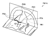
- the superimposed image generator 12 generates a superimposed image PW1 of the tomographic image PO and the insertion path R.
- the three-dimensional model image from the desired line of sight LA in the three-dimensional space in which the two-dimensional tomographic image PO and the three-dimensional insertion path R are arranged is superposed as shown in FIG. This is the image PW1.
- the path image is a two-dimensional path image obtained by projecting the three-dimensional insertion path R onto the tomographic image
- the tomographic image is a predetermined plane tomographic image. That is, the superimposed image PW2 is a normal two-dimensional image.
- the superimposed image PW1 is a three-dimensional model image, and can be changed to a desired state by the operator arbitrarily changing the line of sight LA.
- the line of sight LA is set on an extension of the plane of the tomographic image PO
- the tomographic image PO on the superimposed image PW1 is displayed as a line.
- the surgeon can obtain information on the tissue around the distal end portion 2C.
- the intersection of the path image PR indicating the insertion path R and the tomographic image PO is the position of the tip 2C, and a position display mark P2C is displayed.
- the superimposed image generation unit 12 displays the path image PR1 from the start position mark P7A indicating the position of the pharynx 7A, which is the insertion start position, to the position display mark P2C indicating the position of the tip 2C from the position display mark P2C.
- the path image PR2 up to the target position mark P9G indicating the target position is displayed with a distinguishable different line type. That is, the route image PR1 is displayed with a dotted line, and the route image PR2 is mainly displayed with a solid line.
- the superimposed image generation unit 12 displays a portion of the route image PR2 on the rear side of the tomographic image PO as viewed from the line of sight LA with a broken line.
- the superimposed image generation unit 12 may display the route image PR1 and the route image PR2 in different colors or thicknesses in order to identify them.
- the superimposed image generation unit 12 may not display the route image PR1.
- the superimposed image generation unit 12 may generate a superimposed image PW1A using a composite tomographic image as the tomographic image PO.
- the superimposed image PW1A is a three-dimensional model image of a combined tomographic image composed of two orthogonal planes PA and PC shown in FIG.
- the tip portion 7C is located on the intersection line between the plane PA and the plane PC perpendicular to the direction of the tip portion 7C.
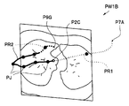
- the superimposed image generation unit 12 may generate a superimposed image PW1B in which the branch portion display marks PJ1 to PJ4 indicating the positions of the respective branch portions are superimposed on the route image PR.
- the superimposed image generation unit 12 may generate a superimposed image PW1C in which the image PR2 of the core line S other than the insertion path is superimposed as the path image PR.
- display restrictions such as displaying only the core line S branched from the insertion path as shown in FIG.
- a display restriction method only a predetermined number of branch cores S may be displayed, or the core S may be displayed for a predetermined length from the branch part J.
- the superimposed image generation unit 12 may generate a superimposed image PW1D having an axial image PA including the position of the distal end portion 2C.
- the superimposed image generation unit 12 may display the tip end display mark P2CD indicating not only the position of the tip end 2C but also the direction of the tip end 2C on the superimposed image PW1D, or display only the direction. May be. That is, a predetermined effect can be obtained if the tip display mark indicates at least one of the position and direction of the tip.
- the superimposed image generation unit 12 may display the rotation angle of the tip 2C on the tip display mark.
- the superimposed image generation unit 12 does not display the route image PR1 of the path from the pharynx 7A to the tip 2C, which is the insertion path that has already passed, and thus the visibility of the superimposed image is good.
- the tomographic image generation unit 14 may generate a coronal image PC or a sagittal image PS including the position of the tip 2C.
- the tomographic image generation unit 14 generates a tomographic image based on the position and direction of the tip 2C, but can also generate a tomographic image based only on the position of the tip 2C.
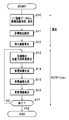
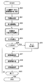
- Step S16> Superimposed Display
- the superimposed image PW1 generated by the superimposed image generating unit 12 is displayed on the display unit 4 together with the real image and the VBS image.
- the superimposed image PW1 may be always displayed on the navigation screen, but the superimposed image PW1 may be temporarily hidden by the operator's setting, or automatically under the control of the control unit 10. The superimposed image PW1 may be hidden. Further, the type of tomographic image displayed on the superimposed image PW1 may be changed by the operator's setting or the control of the control unit 10.
- the image to be displayed on the navigation screen may be selected based on the position of the tip 2C. For example, when the distal end portion 2C approaches the branch portion J, the navigation mode including the superimposed image PW1 is displayed. The navigation screen does not display the superimposed image PW1 after the distal end portion 2C passes the branch portion J. The display mode may be switched to display.
- the switching of the display mode is controlled by the control unit 10 according to the presence or absence of a trigger setting, similarly to the switching of the navigation mode described later (see FIG. 24).
- the insertion navigation mode ends, the treatment tool 6 is projected from the distal end portion 2C, and a biopsy or the like of the target site 9G is performed.
- the medical device 1 allows the operator to easily grasp the position of the distal end portion 2 ⁇ / b> C from the superimposed image displayed on the display unit 4. Furthermore, the operator can grasp the state of the tissue near the distal end portion 2C from the tomographic image PO. For this reason, the medical device 1 can easily insert the distal end portion 2C of the insertion portion 2A up to the target site 9G.
- a medical device 1A according to a second embodiment of the present invention will be described with reference to the drawings. Since the medical device 1A is similar to the medical device 1, the same components are denoted by the same reference numerals and description thereof is omitted.
- the VBS image is not displayed on the navigation screen, and the second route image PR2 indicating the insertion route R is superimposed on the real image.
- the second route image PR2 In order to insert the second route image PR2 into the real image, first, the second route image PR2 to be superimposed on the VBS image corresponding to the real image is generated, and the generated second route image PR2 is real. It is superimposed on the image.
- the surgeon can perform the insertion operation while confirming the insertion path R with the second path image PR2 superimposed and displayed on the real image and grasping the position of the distal end portion 2C with the superimposed image PW1. .
- the medical device 1A has the effects of the medical device 1, and has a simple navigation screen and excellent visibility.
- Various configurations described in the medical device 1 can be used in the medical device 1 ⁇ / b> A, and the configuration of the medical device 1 ⁇ / b> A can be used in the medical device 1.
- the medical device 1B includes a display area calculation unit 30 that is a display area calculation unit.
- the display area calculation unit 30 calculates the display area of the second route PR2 superimposed and displayed on the VBS image.
- the insertion path R is calculated along the core S which is the center of the bronchus 9 having a predetermined thickness. For this reason, as shown to FIG. 16A, the 2nd path
- the superimposed image generation unit 12 highlights the second route image PR2. To do.
- the display area calculation unit 30 counts the number K of pixels of the second path image PR2 in the VBS image composed of 500 ⁇ 500 pixels. Then, when the number of pixels K is equal to or less than the first predetermined value K1, the superimposed image generation unit 12 displays a line for displaying the route image PR so that the number of pixels is K1, for example. That is, the shorter the route displayed in a superimposed manner, the thicker the route image PR is displayed.
- the real image may become partially white, or the color in the lumen and the color of the second route image PR2 may be difficult to distinguish. For this reason, as a highlighting method of the second route image PR2, the color or line type may be changed, or the blinking display may be performed.
- the display area calculation unit 30 calculates the average luminance for pixels in a range of a predetermined region of interest (ROI), not the entire real image RBS, and the second route image PR2 is changed according to the change in the average luminance.
- the display method may be changed so that the visibility is improved.
- the ROI is preferably set in a range surrounding the second route image PR2, and the shape may be any of a circle, an ellipse, a rectangle, a square, and the like. Further, the shape is not limited to a preset shape, and a graphic having a minimum area in the range surrounding the second route image PR2 may be selected for each process, or the second route image PR2 may be selected as a preselected shape. You may enlarge and reduce to the surrounding range.
- the medical device 1 ⁇ / b> C according to the second modification of the second embodiment includes an auxiliary insertion path generation unit 31 that is an auxiliary insertion path generation unit.
- the second route image PR2 may be displayed very short or not at all depending on the position or direction of the tip 2C. Then, it is not easy for the surgeon to recognize the correct insertion path.
- the superimposed image generation unit 12 when the display area of the second route image PR2 calculated by the display area calculation unit 30 is equal to or less than the second predetermined value K2, the superimposed image generation unit 12 The auxiliary insertion path image PSR is superimposed and displayed in place of the second path image PR2 or together with the second path image PR2.
- the second predetermined value K2 may be 0, for example.
- the auxiliary insertion path generation unit 31 uses not only the core information but also volume information as the three-dimensional shape information of the lumen.
- the core line S is a line connecting the center of gravity of the vertical direction of the lumen in the duct direction
- the volume is information indicating the position of the lumen wall.
- the auxiliary insertion path generation unit 31 generates an auxiliary insertion path SR that is a cross line between the plane including the insertion path R and the lumen wall of the bronchus 9 that is volume information.
- FIG. 19A shows a case where the lumen is a straight tube for the sake of explanation. For this reason, the plane including the insertion path R is a two-dimensional plane. However, since the actual lumen is curved, the plane including the insertion path R is also a curved plane.
- FIG. 19A shows a case where four auxiliary insertion paths SR are generated by two orthogonal surfaces including the insertion path R. For this reason, as shown in FIG. 19B, even when the core line S direction and the line-of-sight direction LA coincide, the four auxiliary insertion path images PSR are superimposed on the endoscopic image.
- auxiliary insertion path generation unit 31 may generate four or more, for example, eight auxiliary insertion paths SR.
- the medical devices 1B and 1C have the effects of the medical devices 1 and 1A, and are excellent in the visibility of the insertion path R on the navigation screen.
- Various configurations described in the medical devices 1 and 1A can be used in the medical devices 1B and 1C, and the configurations of the medical devices 1B and 1C can be used in the medical devices 1 and 1A.
- a medical device 1D according to a third embodiment of the present invention will be described with reference to the drawings. Since the medical device 1D is similar to the medical device 1, the same components are denoted by the same reference numerals and description thereof is omitted.
- a magnetic field sensor 21 that is a position sensor is disposed at the distal end portion 2C of the insertion portion 2A of the medical device 1D, and the position calculation unit 20D calculates the position of the distal end portion 2C from the data of the magnetic field sensor 21. The position, direction and rotation angle are calculated.
- the magnetic field sensor detects the magnetic field from the plurality of magnetic field generating antennas 22 disposed outside the subject 7, whereby the position calculation unit 20D detects the position of the tip 2C and the like. That is, since the arrangement position of the magnetic field sensor 21 arranged at the distal end portion 2C and the arrangement position of the imaging unit 2B are known, the position calculation unit 20D determines the line-of-sight position, the line-of-sight direction, and the rotation angle of the imaging unit 2B. Is detected.
- An MR sensor, a Hall element, a coil, or the like can be used as the magnetic field detection sensor.
- the medical device 1D has the same effect as the medical device 1.
- the various configurations described in the medical devices 1, 1A to 1C can be used, and the configuration of the medical device 1D can be used in the medical devices 1, 1A to 1C.
- a magnetic field sensor 21D which is a position sensor, is disposed at the distal end portion 6A of the treatment instrument 6 of the medical device 1DA.
- the position calculation unit 20D calculates the position, direction, and rotation angle of the tip 2C from the data of the magnetic field sensor 21D. Further, during the insertion operation of the treatment instrument 6, the position and direction and the rotation angle of the treatment instrument distal end portion 6A are calculated.
- the treatment tool tip 6A is the cutting edge when the treatment tool is a needle, but may be the center of the cup in the case of a biopsy forceps, and the center of the brush in the case of a brush. Also good.
- the magnetic field sensor 21D is an inductor. You may arrange
- the medical device 1DA has the same effect as the medical device 1D, and can acquire position information of the treatment instrument distal end portion 6A protruding from the channel opening 8E.
- a medical device 1E according to a fourth embodiment of the present invention will be described with reference to the drawings. Since the medical device 1E is similar to the medical device 1, the same components are denoted by the same reference numerals and description thereof is omitted.
- the tomographic image displayed on the navigation screen changes.
- the image displayed on the display unit 4 is selected by the control unit 10 based on the position of the distal end portion 2C. More specifically, when the distance between the position of the distal end portion 2C and the position of the target portion 9G is equal to or less than a predetermined value, or when the last branch portion is passed, the navigation mode is set to insert portion insertion.
- the support mode is switched to the treatment instrument operation support mode. Of course, the surgeon may select the navigation mode.
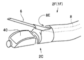
- an imaging unit 2B and an illumination unit 2B1 are disposed at the distal end portion 2C of the medical device 1E, and the treatment tool 6 can protrude from the channel opening 8E.
- the position of the channel opening 8E is different from the position of the imaging unit 2B.
- the medical device 1E preferably uses the position of the channel opening 8E as the position of the distal end portion 2C.
- the tomographic image generation unit 14 generates a tomographic image PPE including the position of the channel opening 8E and a plane parallel to the axial direction of the channel 8, that is, a plane parallel to the direction of the distal end portion 2C. Further, as shown in FIG. 23, the superimposed image generation unit 12 generates a superimposed image PW1E in which the extension line P8S of the channel 8 is superimposed and displayed on the tomographic image PPE.
- the extension line 8S indicates the direction in which the treatment tool 6 protrudes from the channel opening 8E.
- the scale may be added to the extension line P8S, or the color may be changed according to the length. Further, the direction of the extension line P8S may have a predetermined angle with respect to the direction of the distal end portion 2C, and the angle can be arbitrarily changed by the operator.
- Steps S20 to S23> This is the same as steps S10 to S13 of the medical device 1 of the first embodiment described with reference to FIG.
- a trigger is set by the control unit 10 according to the position of the distal end portion 2C calculated in S21.
- the trigger is set when the distance between the position of the distal end portion 2C and the target site 9G is equal to or less than a predetermined value.
- the distance between the position of the tip 2C and the target site 9G may be a linear distance or an insertion path distance via the core wire S.
- the trigger has a predetermined difference between the inner diameter of the bronchus 9 at the position of the distal end 2C or a predetermined value or a difference between the inner diameter of the bronchus 9 at the position of the distal end 2C and the outer diameter of the insertion part 2A. Set when the value falls below the value.
- the trigger may be set not only automatically by the control unit 10 but also by a setting operation via the operator's input unit 5.
- the trigger may be set by detecting that the image of the treatment tool 6 is reflected in the real image, that is, that the surgeon protrudes the treatment tool 6 from the channel opening 8E and starts biopsy.
- the treatment tool 6 protrudes from the channel opening 8E, the luminance of pixels in a range of a predetermined region of interest (ROI) of the real image increases. For this reason, an average luminance may be calculated for the ROI, and a trigger may be set according to a change in the average luminance.
- ROI region of interest
- Steps S27 to S30> This is the same as steps S14 to S17 of the medical device 1 according to the first embodiment described with reference to FIG.
- the medical device 1E has the same effect as the medical device 1 and the like, and further performs treatment tool operation support after the distal end portion 2C is inserted to the vicinity of the target site 9G.
- the various configurations described in the medical devices 1, 1A to 1D can be used, and the configuration of the medical device 1E can be used in the medical devices 1, 1A to 1D.
- a medical device 1F according to a fifth embodiment of the present invention will be described with reference to the drawings. Since the medical device 1F is similar to the medical device 1, the same components are denoted by the same reference numerals and description thereof is omitted.
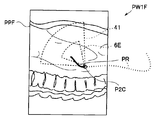
- the endoscope apparatus 2F of the medical device 1F has a convex scanning type ultrasonic transducer 40 for scanning an arcuate range at the distal end portion 2C.
- the operator can confirm the position of the lymph node or blood vessel by the ultrasonic image.
- the tomographic image generation unit 14 switches the navigation mode to the treatment instrument operation support mode, includes the position of the distal end portion 2C, and scans the ultrasonic transducer 40.
- a planar tomographic image PPF (see FIG. 26) is generated.
- the superimposed image generation unit 12 can treat the tomographic image PPF with the scanning range 41 of the ultrasonic transducer 40 and the treatment instrument 6 protruding from the channel opening 8E.
- a superimposed image PW1F in which the range 6E is displayed in a superimposed manner is generated.
- the surgeon can grasp the three-dimensional relationship between the scanning range 41 and the treatable range 6E by changing the line-of-sight position of the superimposed image PW1F, which is a three-dimensional model image.
- the navigation mode is switched by detecting the trigger setting as in the medical device 1E of the fourth embodiment.
- the medical device 1F has the same effect as the medical device 1 and the like, and further performs operation tool operation support after the distal end portion 2C is inserted to the vicinity of the target site 9G.
- the various configurations described in the medical devices 1, 1A to 1E can be used, and the configuration of the medical device 1F can be used in the medical devices 1, 1A to 1E.
- the medical device of the embodiment can also be used when observing the whole without determining the target site as in screening.
- the locus of the endoscope tip is displayed instead of the insertion path.
- the point constituting the trajectory may be a position obtained by the position calculating means, or a point on the center line of the luminal organ in the vicinity of the obtained position.
- the trajectory to be displayed may be a movement history indicating all movements of the endoscope tip so far, or may be only a trajectory within a predetermined period or a predetermined space range.
- by displaying the center line of the luminal organ superimposed on the trajectory it is easy to determine which part has been observed.
- a trajectory indicating all movement of the endoscope tip up to that point is displayed. Also good.
- the line indicating the endoscope tip position deeper than the carina, that is, the trajectory can be discriminated by displaying it in a different color or by displaying it with a dotted line.
Priority Applications (4)
| Application Number | Priority Date | Filing Date | Title |
|---|---|---|---|
| JP2012533423A JP5160699B2 (ja) | 2011-01-24 | 2011-11-08 | 医療機器 |
| CN201180038533.3A CN103068294B (zh) | 2011-01-24 | 2011-11-08 | 医疗设备 |
| EP11857389.8A EP2581029B1 (de) | 2011-01-24 | 2011-11-08 | Medizinische vorrichtung |
| US13/556,732 US20120287238A1 (en) | 2011-01-24 | 2012-07-24 | Medical device |
Applications Claiming Priority (2)
| Application Number | Priority Date | Filing Date | Title |
|---|---|---|---|
| JP2011012103 | 2011-01-24 | ||
| JP2011-012103 | 2011-01-24 |
Related Child Applications (1)
| Application Number | Title | Priority Date | Filing Date |
|---|---|---|---|
| US13/556,732 Continuation US20120287238A1 (en) | 2011-01-24 | 2012-07-24 | Medical device |
Publications (1)
| Publication Number | Publication Date |
|---|---|
| WO2012101888A1 true WO2012101888A1 (ja) | 2012-08-02 |
Family
ID=46580474
Family Applications (1)
| Application Number | Title | Priority Date | Filing Date |
|---|---|---|---|
| PCT/JP2011/075686 WO2012101888A1 (ja) | 2011-01-24 | 2011-11-08 | 医療機器 |
Country Status (5)
| Country | Link |
|---|---|
| US (1) | US20120287238A1 (de) |
| EP (1) | EP2581029B1 (de) |
| JP (1) | JP5160699B2 (de) |
| CN (1) | CN103068294B (de) |
| WO (1) | WO2012101888A1 (de) |
Cited By (13)
| Publication number | Priority date | Publication date | Assignee | Title |
|---|---|---|---|---|
| WO2014024995A1 (ja) * | 2012-08-08 | 2014-02-13 | 株式会社東芝 | 医用画像診断装置、画像処理装置及び画像処理方法 |
| WO2014141968A1 (ja) * | 2013-03-12 | 2014-09-18 | オリンパスメディカルシステムズ株式会社 | 内視鏡システム |
| CN104755009A (zh) * | 2013-04-15 | 2015-07-01 | 奥林巴斯医疗株式会社 | 内窥镜系统 |
| JP2015198826A (ja) * | 2014-04-09 | 2015-11-12 | コニカミノルタ株式会社 | 超音波画像診断装置及び超音波画像表示方法 |
| EP2912987A4 (de) * | 2012-10-25 | 2016-07-06 | Olympus Corp | Einsatzsystem, einsatzunterstützungsvorrichtung, einsatzunterstützungsverfahren und programm |
| JP2016179121A (ja) * | 2015-03-25 | 2016-10-13 | 富士フイルム株式会社 | 内視鏡検査支援装置、方法およびプログラム |
| JP2016221095A (ja) * | 2015-06-02 | 2016-12-28 | 株式会社島津製作所 | 放射線透視装置 |
| JP2017055954A (ja) * | 2015-09-16 | 2017-03-23 | 富士フイルム株式会社 | 内視鏡位置特定装置、方法およびプログラム |
| JP2017093729A (ja) * | 2015-11-20 | 2017-06-01 | ザイオソフト株式会社 | 医用画像処理装置、医用画像処理方法、及び医用画像処理プログラム |
| JP2017525418A (ja) * | 2014-07-02 | 2017-09-07 | コヴィディエン リミテッド パートナーシップ | インテリジェントディスプレイ |
| JP2019042506A (ja) * | 2017-08-31 | 2019-03-22 | バイオセンス・ウエブスター・(イスラエル)・リミテッドBiosense Webster (Israel), Ltd. | 解剖学的画像における内視鏡の位置及び光軸の表示 |
| JPWO2020090729A1 (ja) * | 2018-11-01 | 2021-09-24 | 富士フイルム株式会社 | 医療画像処理装置、医療画像処理方法及びプログラム、診断支援装置 |
| WO2021192593A1 (ja) * | 2020-03-26 | 2021-09-30 | Hoya株式会社 | プログラム、情報処理方法、情報処理装置及び診断支援システム |
Families Citing this family (45)
| Publication number | Priority date | Publication date | Assignee | Title |
|---|---|---|---|---|
| US20140253544A1 (en) * | 2012-01-27 | 2014-09-11 | Kabushiki Kaisha Toshiba | Medical image processing apparatus |
| CN104797186B (zh) * | 2013-03-06 | 2016-10-12 | 奥林巴斯株式会社 | 内窥镜系统 |
| US9639666B2 (en) | 2013-03-15 | 2017-05-02 | Covidien Lp | Pathway planning system and method |
| US9459770B2 (en) | 2013-03-15 | 2016-10-04 | Covidien Lp | Pathway planning system and method |
| US9925009B2 (en) | 2013-03-15 | 2018-03-27 | Covidien Lp | Pathway planning system and method |
| CN103169445B (zh) * | 2013-04-16 | 2016-07-06 | 苏州朗开医疗技术有限公司 | 一种内窥镜的导航方法及系统 |
| KR101466153B1 (ko) * | 2013-05-02 | 2014-11-27 | 삼성메디슨 주식회사 | 의료 영상 장치 및 그 제어 방법 |
| WO2014203625A1 (ja) * | 2013-06-18 | 2014-12-24 | オリンパスメディカルシステムズ株式会社 | 内視鏡システム、内視鏡システムの制御方法 |
| JP5810248B2 (ja) * | 2013-10-02 | 2015-11-11 | オリンパス株式会社 | 内視鏡システム |
| JP6725423B2 (ja) * | 2014-02-11 | 2020-07-15 | コーニンクレッカ フィリップス エヌ ヴェKoninklijke Philips N.V. | 解剖学的標的を視覚化するシステム |
| KR102358967B1 (ko) * | 2014-03-17 | 2022-02-08 | 인튜어티브 서지컬 오퍼레이션즈 인코포레이티드 | 이미징 기기의 방향 제어 시스템 및 방법 |
| AU2015284303B2 (en) | 2014-07-02 | 2019-07-25 | Covidien Lp | System and method for detecting trachea |
| US20160000414A1 (en) | 2014-07-02 | 2016-01-07 | Covidien Lp | Methods for marking biopsy location |
| US9603668B2 (en) | 2014-07-02 | 2017-03-28 | Covidien Lp | Dynamic 3D lung map view for tool navigation inside the lung |
| CA2953146A1 (en) | 2014-07-02 | 2016-01-07 | Covidien Lp | System and method for segmentation of lung |
| US9770216B2 (en) | 2014-07-02 | 2017-09-26 | Covidien Lp | System and method for navigating within the lung |
| JP6534193B2 (ja) | 2014-07-02 | 2019-06-26 | コヴィディエン リミテッド パートナーシップ | 実時間自動位置合わせフィードバック |
| US9754367B2 (en) | 2014-07-02 | 2017-09-05 | Covidien Lp | Trachea marking |
| US10643371B2 (en) | 2014-08-11 | 2020-05-05 | Covidien Lp | Treatment procedure planning system and method |
| US10986990B2 (en) | 2015-09-24 | 2021-04-27 | Covidien Lp | Marker placement |
| US10709352B2 (en) | 2015-10-27 | 2020-07-14 | Covidien Lp | Method of using lung airway carina locations to improve ENB registration |
| JP6608111B2 (ja) * | 2016-09-28 | 2019-11-20 | 富士フイルム株式会社 | 医用画像保存再生装置および方法並びにプログラム |
| CN106691504A (zh) * | 2016-11-29 | 2017-05-24 | 深圳开立生物医疗科技股份有限公司 | 自定义导航切面的方法、装置及超声设备 |
| JP6745748B2 (ja) * | 2017-03-16 | 2020-08-26 | 富士フイルム株式会社 | 内視鏡位置特定装置、その作動方法およびプログラム |
| US11166764B2 (en) | 2017-07-27 | 2021-11-09 | Carlsmed, Inc. | Systems and methods for assisting and augmenting surgical procedures |
| CN109620407B (zh) * | 2017-10-06 | 2024-02-06 | 皇家飞利浦有限公司 | 治疗轨迹引导系统 |
| US11112770B2 (en) * | 2017-11-09 | 2021-09-07 | Carlsmed, Inc. | Systems and methods for assisting a surgeon and producing patient-specific medical devices |
| US11083586B2 (en) | 2017-12-04 | 2021-08-10 | Carlsmed, Inc. | Systems and methods for multi-planar orthopedic alignment |
| US10984585B2 (en) * | 2017-12-13 | 2021-04-20 | Covidien Lp | Systems, methods, and computer-readable media for automatic computed tomography to computed tomography registration |
| US11224392B2 (en) | 2018-02-01 | 2022-01-18 | Covidien Lp | Mapping disease spread |
| US11123139B2 (en) | 2018-02-14 | 2021-09-21 | Epica International, Inc. | Method for determination of surgical procedure access |
| US11432943B2 (en) | 2018-03-14 | 2022-09-06 | Carlsmed, Inc. | Systems and methods for orthopedic implant fixation |
| US11439514B2 (en) | 2018-04-16 | 2022-09-13 | Carlsmed, Inc. | Systems and methods for orthopedic implant fixation |
| JP7023196B2 (ja) * | 2018-07-13 | 2022-02-21 | 富士フイルム株式会社 | 検査支援装置、方法およびプログラム |
| USD958151S1 (en) | 2018-07-30 | 2022-07-19 | Carlsmed, Inc. | Display screen with a graphical user interface for surgical planning |
| WO2020056186A1 (en) | 2018-09-12 | 2020-03-19 | Carlsmed, Inc. | Systems and methods for orthopedic implants |
| CN109646110B (zh) * | 2019-01-24 | 2022-06-10 | 苏州朗开医疗技术有限公司 | 一种电视辅助胸腔镜定位方法及装置 |
| US11730340B2 (en) * | 2019-05-01 | 2023-08-22 | Karl Storz Imaging, Inc. | Video display system having an adaptive overlay |
| KR102097390B1 (ko) * | 2019-10-10 | 2020-04-06 | 주식회사 메디씽큐 | 시선 검출 기반의 스마트 안경 표시 장치 |
| US11376076B2 (en) | 2020-01-06 | 2022-07-05 | Carlsmed, Inc. | Patient-specific medical systems, devices, and methods |
| US10902944B1 (en) | 2020-01-06 | 2021-01-26 | Carlsmed, Inc. | Patient-specific medical procedures and devices, and associated systems and methods |
| EP4167892A1 (de) | 2020-06-19 | 2023-04-26 | Remedy Robotics, Inc. | Systeme und verfahren zur führung intraluminaler vorrichtungen im gefässsystem |
| AU2022305235A1 (en) * | 2021-07-01 | 2024-01-18 | Remedy Robotics, Inc. | Vision-based position and orientation determination for endovascular tools |
| US11707332B2 (en) | 2021-07-01 | 2023-07-25 | Remedy Robotics, Inc. | Image space control for endovascular tools |
| US11443838B1 (en) | 2022-02-23 | 2022-09-13 | Carlsmed, Inc. | Non-fungible token systems and methods for storing and accessing healthcare data |
Citations (9)
| Publication number | Priority date | Publication date | Assignee | Title |
|---|---|---|---|---|
| JP2003265408A (ja) | 2002-03-19 | 2003-09-24 | Mitsubishi Electric Corp | 内視鏡誘導装置および方法 |
| JP2004089483A (ja) * | 2002-08-30 | 2004-03-25 | Olympus Corp | 内視鏡装置 |
| JP2004180940A (ja) | 2002-12-03 | 2004-07-02 | Olympus Corp | 内視鏡装置 |
| JP2005131042A (ja) | 2003-10-29 | 2005-05-26 | Olympus Corp | 挿入支援システム |
| JP2005304937A (ja) * | 2004-04-23 | 2005-11-04 | Olympus Corp | 挿入支援システム |
| JP2006181110A (ja) * | 2004-12-27 | 2006-07-13 | Olympus Corp | 挿入支援システム |
| WO2007129493A1 (ja) * | 2006-05-02 | 2007-11-15 | National University Corporation Nagoya University | 医療画像観察支援装置 |
| JP2010517632A (ja) * | 2007-01-31 | 2010-05-27 | ザ ペン ステイト リサーチ ファンデーション | 内視鏡の継続的案内のためのシステム |
| JP4728456B1 (ja) * | 2010-02-22 | 2011-07-20 | オリンパスメディカルシステムズ株式会社 | 医療機器 |
Family Cites Families (4)
| Publication number | Priority date | Publication date | Assignee | Title |
|---|---|---|---|---|
| US6346940B1 (en) * | 1997-02-27 | 2002-02-12 | Kabushiki Kaisha Toshiba | Virtualized endoscope system |
| WO2004010857A1 (ja) * | 2002-07-31 | 2004-02-05 | Olympus Corporation | 内視鏡装置 |
| JP4022192B2 (ja) * | 2003-10-31 | 2007-12-12 | オリンパス株式会社 | 挿入支援システム |
| JP4981335B2 (ja) * | 2006-03-08 | 2012-07-18 | オリンパスメディカルシステムズ株式会社 | 医療用画像処理装置及び医療用画像処理方法 |
-
2011
- 2011-11-08 EP EP11857389.8A patent/EP2581029B1/de not_active Not-in-force
- 2011-11-08 CN CN201180038533.3A patent/CN103068294B/zh active Active
- 2011-11-08 WO PCT/JP2011/075686 patent/WO2012101888A1/ja active Application Filing
- 2011-11-08 JP JP2012533423A patent/JP5160699B2/ja not_active Expired - Fee Related
-
2012
- 2012-07-24 US US13/556,732 patent/US20120287238A1/en not_active Abandoned
Patent Citations (9)
| Publication number | Priority date | Publication date | Assignee | Title |
|---|---|---|---|---|
| JP2003265408A (ja) | 2002-03-19 | 2003-09-24 | Mitsubishi Electric Corp | 内視鏡誘導装置および方法 |
| JP2004089483A (ja) * | 2002-08-30 | 2004-03-25 | Olympus Corp | 内視鏡装置 |
| JP2004180940A (ja) | 2002-12-03 | 2004-07-02 | Olympus Corp | 内視鏡装置 |
| JP2005131042A (ja) | 2003-10-29 | 2005-05-26 | Olympus Corp | 挿入支援システム |
| JP2005304937A (ja) * | 2004-04-23 | 2005-11-04 | Olympus Corp | 挿入支援システム |
| JP2006181110A (ja) * | 2004-12-27 | 2006-07-13 | Olympus Corp | 挿入支援システム |
| WO2007129493A1 (ja) * | 2006-05-02 | 2007-11-15 | National University Corporation Nagoya University | 医療画像観察支援装置 |
| JP2010517632A (ja) * | 2007-01-31 | 2010-05-27 | ザ ペン ステイト リサーチ ファンデーション | 内視鏡の継続的案内のためのシステム |
| JP4728456B1 (ja) * | 2010-02-22 | 2011-07-20 | オリンパスメディカルシステムズ株式会社 | 医療機器 |
Non-Patent Citations (1)
| Title |
|---|
| See also references of EP2581029A4 * |
Cited By (25)
| Publication number | Priority date | Publication date | Assignee | Title |
|---|---|---|---|---|
| CN103764041B (zh) * | 2012-08-08 | 2015-12-09 | 株式会社东芝 | 医用图像诊断装置、图像处理装置以及图像处理方法 |
| JP2014050684A (ja) * | 2012-08-08 | 2014-03-20 | Toshiba Corp | 医用画像診断装置、画像処理装置及び画像処理方法 |
| CN103764041A (zh) * | 2012-08-08 | 2014-04-30 | 株式会社东芝 | 医用图像诊断装置、图像处理装置以及图像处理方法 |
| US10123780B2 (en) | 2012-08-08 | 2018-11-13 | Toshiba Medical Systems Corporation | Medical image diagnosis apparatus, image processing apparatus, and image processing method |
| WO2014024995A1 (ja) * | 2012-08-08 | 2014-02-13 | 株式会社東芝 | 医用画像診断装置、画像処理装置及び画像処理方法 |
| EP2912987A4 (de) * | 2012-10-25 | 2016-07-06 | Olympus Corp | Einsatzsystem, einsatzunterstützungsvorrichtung, einsatzunterstützungsverfahren und programm |
| JP5718537B2 (ja) * | 2013-03-12 | 2015-05-13 | オリンパスメディカルシステムズ株式会社 | 内視鏡システム |
| US9326660B2 (en) | 2013-03-12 | 2016-05-03 | Olympus Corporation | Endoscope system with insertion support apparatus |
| WO2014141968A1 (ja) * | 2013-03-12 | 2014-09-18 | オリンパスメディカルシステムズ株式会社 | 内視鏡システム |
| CN104755009A (zh) * | 2013-04-15 | 2015-07-01 | 奥林巴斯医疗株式会社 | 内窥镜系统 |
| JP2015198826A (ja) * | 2014-04-09 | 2015-11-12 | コニカミノルタ株式会社 | 超音波画像診断装置及び超音波画像表示方法 |
| US11188285B2 (en) | 2014-07-02 | 2021-11-30 | Covidien Lp | Intelligent display |
| US11793389B2 (en) | 2014-07-02 | 2023-10-24 | Covidien Lp | Intelligent display |
| JP2017525418A (ja) * | 2014-07-02 | 2017-09-07 | コヴィディエン リミテッド パートナーシップ | インテリジェントディスプレイ |
| JP2016179121A (ja) * | 2015-03-25 | 2016-10-13 | 富士フイルム株式会社 | 内視鏡検査支援装置、方法およびプログラム |
| JP2016221095A (ja) * | 2015-06-02 | 2016-12-28 | 株式会社島津製作所 | 放射線透視装置 |
| JP2017055954A (ja) * | 2015-09-16 | 2017-03-23 | 富士フイルム株式会社 | 内視鏡位置特定装置、方法およびプログラム |
| JP2017093729A (ja) * | 2015-11-20 | 2017-06-01 | ザイオソフト株式会社 | 医用画像処理装置、医用画像処理方法、及び医用画像処理プログラム |
| JP2019042506A (ja) * | 2017-08-31 | 2019-03-22 | バイオセンス・ウエブスター・(イスラエル)・リミテッドBiosense Webster (Israel), Ltd. | 解剖学的画像における内視鏡の位置及び光軸の表示 |
| JP7350470B2 (ja) | 2017-08-31 | 2023-09-26 | バイオセンス・ウエブスター・(イスラエル)・リミテッド | 解剖学的画像における内視鏡の位置及び光軸の表示 |
| JPWO2020090729A1 (ja) * | 2018-11-01 | 2021-09-24 | 富士フイルム株式会社 | 医療画像処理装置、医療画像処理方法及びプログラム、診断支援装置 |
| JP7315576B2 (ja) | 2018-11-01 | 2023-07-26 | 富士フイルム株式会社 | 医療画像処理装置、医療画像処理装置の作動方法及びプログラム、診断支援装置、ならびに内視鏡システム |
| WO2021192593A1 (ja) * | 2020-03-26 | 2021-09-30 | Hoya株式会社 | プログラム、情報処理方法、情報処理装置及び診断支援システム |
| JP2021153808A (ja) * | 2020-03-26 | 2021-10-07 | Hoya株式会社 | プログラム、情報処理方法、情報処理装置及び診断支援システム |
| JP7254742B2 (ja) | 2020-03-26 | 2023-04-10 | Hoya株式会社 | プログラム、情報処理方法、情報処理装置及び診断支援システム |
Also Published As
| Publication number | Publication date |
|---|---|
| JPWO2012101888A1 (ja) | 2014-06-30 |
| CN103068294B (zh) | 2015-06-24 |
| JP5160699B2 (ja) | 2013-03-13 |
| EP2581029A4 (de) | 2013-07-24 |
| EP2581029B1 (de) | 2014-12-31 |
| EP2581029A1 (de) | 2013-04-17 |
| CN103068294A (zh) | 2013-04-24 |
| US20120287238A1 (en) | 2012-11-15 |
Similar Documents
| Publication | Publication Date | Title |
|---|---|---|
| JP5160699B2 (ja) | 医療機器 | |
| JP5718537B2 (ja) | 内視鏡システム | |
| JP7154832B2 (ja) | 形状推定をともなう軌道情報による位置合わせの改良 | |
| JP5188879B2 (ja) | 医療機器 | |
| WO2011102012A1 (ja) | 医療機器 | |
| JP5380348B2 (ja) | 内視鏡観察を支援するシステムおよび方法、並びに、装置およびプログラム | |
| US8414476B2 (en) | Method for using variable direction of view endoscopy in conjunction with image guided surgical systems | |
| EP2888991B1 (de) | Endoskopsystem | |
| EP2641561A1 (de) | System und Verfahren zum Bestimmen von Kamerawinkeln durch das Verwenden von virtuellen Ebenen, die von tatsächlichen Bildern abgeleitet wurden | |
| JP5580758B2 (ja) | 蛍光観察装置 | |
| US20180235716A1 (en) | Insertion unit support system | |
| JP3850217B2 (ja) | 気管支用内視鏡位置検出装置 | |
| JP4728456B1 (ja) | 医療機器 | |
| JP2017225700A (ja) | 観察支援装置及び内視鏡システム | |
| US9345394B2 (en) | Medical apparatus | |
| JP2020058779A (ja) | ユーザーを支援する方法、コンピュータープログラム製品、データ記憶媒体、及び撮像システム | |
| US20230372024A1 (en) | Synthetic position in space of an endoluminal instrument | |
| US20210052146A1 (en) | Systems and methods for selectively varying resolutions |
Legal Events
| Date | Code | Title | Description |
|---|---|---|---|
| WWE | Wipo information: entry into national phase |
Ref document number: 201180038533.3 Country of ref document: CN |
|
| WWE | Wipo information: entry into national phase |
Ref document number: 2012533423 Country of ref document: JP |
|
| 121 | Ep: the epo has been informed by wipo that ep was designated in this application |
Ref document number: 11857389 Country of ref document: EP Kind code of ref document: A1 |
|
| WWE | Wipo information: entry into national phase |
Ref document number: 2011857389 Country of ref document: EP |
|
| NENP | Non-entry into the national phase |
Ref country code: DE |