WO2012098946A1 - 自動分析装置 - Google Patents
自動分析装置 Download PDFInfo
- Publication number
- WO2012098946A1 WO2012098946A1 PCT/JP2012/050243 JP2012050243W WO2012098946A1 WO 2012098946 A1 WO2012098946 A1 WO 2012098946A1 JP 2012050243 W JP2012050243 W JP 2012050243W WO 2012098946 A1 WO2012098946 A1 WO 2012098946A1
- Authority
- WO
- WIPO (PCT)
- Prior art keywords
- light
- automatic analyzer
- detector
- substance
- light source
- Prior art date
Links
Images


Classifications
-
- G—PHYSICS
- G01—MEASURING; TESTING
- G01N—INVESTIGATING OR ANALYSING MATERIALS BY DETERMINING THEIR CHEMICAL OR PHYSICAL PROPERTIES
- G01N21/00—Investigating or analysing materials by the use of optical means, i.e. using sub-millimetre waves, infrared, visible or ultraviolet light
- G01N21/17—Systems in which incident light is modified in accordance with the properties of the material investigated
- G01N21/47—Scattering, i.e. diffuse reflection
- G01N21/49—Scattering, i.e. diffuse reflection within a body or fluid
- G01N21/51—Scattering, i.e. diffuse reflection within a body or fluid inside a container, e.g. in an ampoule
-
- G—PHYSICS
- G01—MEASURING; TESTING
- G01N—INVESTIGATING OR ANALYSING MATERIALS BY DETERMINING THEIR CHEMICAL OR PHYSICAL PROPERTIES
- G01N35/00—Automatic analysis not limited to methods or materials provided for in any single one of groups G01N1/00 - G01N33/00; Handling materials therefor
- G01N35/00584—Control arrangements for automatic analysers
- G01N35/00594—Quality control, including calibration or testing of components of the analyser
- G01N35/00693—Calibration
-
- G—PHYSICS
- G01—MEASURING; TESTING
- G01N—INVESTIGATING OR ANALYSING MATERIALS BY DETERMINING THEIR CHEMICAL OR PHYSICAL PROPERTIES
- G01N2201/00—Features of devices classified in G01N21/00
- G01N2201/04—Batch operation; multisample devices
- G01N2201/0415—Carrusel, sequential
-
- G—PHYSICS
- G01—MEASURING; TESTING
- G01N—INVESTIGATING OR ANALYSING MATERIALS BY DETERMINING THEIR CHEMICAL OR PHYSICAL PROPERTIES
- G01N2201/00—Features of devices classified in G01N21/00
- G01N2201/12—Circuits of general importance; Signal processing
- G01N2201/121—Correction signals
- G01N2201/1211—Correction signals for temperature
Definitions
- the present invention relates to an automatic analyzer that analyzes the amount of components contained in a sample such as blood or urine, and in particular is a technology capable of correcting drift due to thermal deformation of an optical system.
- an analyzer that analyzes the amount of components contained in the sample, the light from the light source is irradiated to the sample or the reaction solution in which the sample and the reagent are mixed, and the amount of transmitted light of one or more wavelengths obtained as a result is measured
- An automatic analyzer is widely used which calculates the absorbance and calculates the component amount from the relationship between absorbance and concentration according to Lambert-Beer's law (see Patent Document 1).
- reaction containers for holding the reaction solution are circumferentially arranged on the reaction disc which repeatedly rotates and stops, and about 10 of the transmitted light measurement units arranged in advance during the rotation of the reaction disc.
- the change in absorbance over time is measured at constant time intervals for a minute. After the measurement, the reaction vessel is washed by the washing mechanism and used again for analysis.
- reaction of the reaction solution two major types of reactions, a color reaction of a substrate and an enzyme, and an agglutination reaction of an antigen and an antibody, are used.
- test items include LDH (lactate dehydrogenase), ALP (alkaline phosphatase), AST (aspartate aminotransferase) and the like.
- LDH lactate dehydrogenase
- ALP alkaline phosphatase
- AST aspartate aminotransferase
- test items include CRP (C-reactive protein), IgG (immunoglobulin), RF (rheumatoid factor) and the like.
- the measurement substance measured by the latter immunoassay is low in blood concentration, a highly sensitive detection system is required.
- a reagent in which an antibody is sensitized (bound) to the surface of latex particles and aggregating latex particles by an antigen-antibody reaction with an antigen contained in a sample the reaction solution is irradiated with light, High sensitivity has been achieved in the latex agglutination method in which the amount of components contained in a sample is quantified by measuring the amount of light transmitted without being scattered into a mass.
- an automatic analyzer it is attempted not to measure the amount of transmitted light but to increase the sensitivity by measuring the amount of scattered light.
- drift of light quantity data caused by a slight fluctuation of the temperature in the apparatus also becomes a major obstacle in detecting a very small change in light quantity at high sensitivity.
- the drift of the light quantity data is roughly classified into (1) drift of light source, (2) drift of electric circuit system, and (3) drift due to thermal deformation of optical system.
- (1) A technology for monitoring and correcting the amount of irradiation light (see Patent Document 2) for drift of light source is known, and (2) temperature control of circuit board storage for drift of electric circuit system
- Patent Document 3 for suppressing a drift derived from a circuit by
- the thermal deformation of the optical system is affected not only by the thermal deformation of the photometer, but also by the thermal deformation of the mechanism base on which the photometer is mounted, and these thermal deformations are heat sources (motors and substrates individually controlled individually) Control is very difficult because it is affected by complex temperature changes between the heat exchanger and the ambient temperature. Furthermore, in a turntable-type automatic analyzer that performs measurement while rotating the reaction disk, the photometer must have a shape in which the region through which the reaction container passes is cut off, and the shape is disadvantageous for thermal deformation. It is.
- the object of the present invention is to correct the fluctuation of the light quantity data due to the thermal deformation of the optical system due to the temperature fluctuation inside the apparatus without increasing the size and complexity of the apparatus, and to detect the target substance with high sensitivity. It provides an automatic analyzer.
- An automatic analyzer comprises a light source for irradiating light to a reaction container disposed at a photometric position and containing a mixture of a sample and a reagent, and scattered light or transmitted light from the mixture.
- An automatic analyzer comprising a detector for detecting, wherein the detectors are arranged symmetrically in the vertical direction centering on the optical axis of the irradiation light from the light source, and the light amount data from each detector is The averaged value and / or sum is used to calculate the concentration of the substance to be measured in the mixture.
- the automatic analyzer irradiates light from a light source to a reaction container which is disposed at a photometric position and which contains a mixture of a sample and a reagent, and transmits scattered light or transmission from the mixture. It is an automatic analyzer which detects light with a detector to obtain light quantity data, and calculates the concentration of a substance to be measured in the liquid mixture from the light quantity data, wherein the detector is an optical axis of light emitted from the light source. If the ratio and / or difference of the light quantity data from each detector deviates from a preset range, the light quantity data is not used to calculate the concentration of the substance to be measured.
- an automatic analyzer irradiates light from a light source to a reaction container which is disposed at a photometric position and which contains a mixture of a sample and a reagent, and the scattered light from the mixture
- it is an automatic analyzer that detects transmitted light and obtains light quantity data, and calculates the concentration of a substance to be measured in the liquid mixture from the light quantity data, wherein the detector is an irradiated light from the light source.
- the reaction container is disposed at one or more pairs symmetrically in the vertical direction centering on the optical axis, and the reference substance for calculating the concentration of the substance to be measured is disposed at the photometric position, and the light quantity of the reference substance from each detector The amount of drift at preset time of data is calculated prior to the calculation of the concentration of the substance to be measured.
- one or more sets of detectors for detecting scattered light or transmitted light from the reaction vessel are disposed symmetrically with respect to the optical axis of the irradiation light from the light source, so the value of the light quantity data from each detector
- (A) to (j) are operation flow diagrams of the light quantity data drift check before the start of analysis by the automatic analyzer of the present invention.
- (A) to (m) are operation flow diagrams of the light amount data drift check during analysis by the automatic analyzer of the present invention.
- FIG. 1 is a system block diagram showing an entire configuration of an automatic analyzer according to an embodiment of the present invention.
- the automatic analyzer 1 mainly includes a reaction disk 10, a sample disk 20, reagent disks 30a and 30b, a light source 40, a scattering photometer 41, and a computer 50.
- the reaction disk 10 is provided so as to be capable of intermittent rotation, and a large number of reaction containers 11 made of a translucent material are mounted on the disk along the circumferential direction.
- the reaction container 11 is maintained at a predetermined temperature (for example, 37 ° C.) by the thermostat 12.
- the fluid in the thermostatic chamber 12 is temperature-controlled by the thermostatic maintenance device 13.
- sample containers 21 containing biological samples such as blood and urine are mounted on the sample disc 20 along the circumferential direction in a double manner in the illustrated example. Further, in the vicinity of the sample disk 20, a sample dispensing mechanism 22 is disposed.
- the sample dispensing mechanism 22 mainly includes a movable arm 23 and a pipette nozzle 24 attached thereto. With this configuration, at the time of sample dispensing, the sample dispensing mechanism 22 appropriately moves the pipette nozzle 24 to the dispensing position by the movable arm 23, and a predetermined amount of sample is transferred from the sample container 21 positioned at the suction position of the sample disc 20. The sample is sucked and discharged into the reaction container 11 at the discharge position on the reaction disk 10.
- the reagent disks 30a and 30b are disks having substantially the same diameter and the same shape, and the reagent storage containers 31a and 31b are disposed along the circumferential direction.
- a plurality of reagent bottles 32a and 32b with labels indicating reagent identification information such as barcodes are mounted on the reagent storage containers 31a and 31b along the circumferential direction of the reagent disks 30a and 30b, respectively. ing.
- reagent solutions corresponding to analysis items that can be analyzed by the automatic analyzer 1 are stored.
- each reagent storage compartment 31a, 31b is attached with a barcode reader 33a, 33b, which reads the barcode displayed on the outer wall of each reagent bottle 32a, 32b at the time of reagent registration.
- the read reagent information is registered in the memory 56 together with the position on the reagent disc 30a, 30b.
- reagent dispensing mechanisms 34a and 34b having substantially the same mechanism as the sample dispensing mechanism 22 are disposed, respectively.
- the reagent solution is sucked from the reagent bottles 32 a and 32 b according to the inspection item positioned at the reagent receiving position on the reaction disc 10 by the pipette nozzles provided therein, and discharged into the corresponding reaction container 11.
- Stirring mechanisms 35a and 35b are disposed at positions surrounded by the reaction disk 10, the reagent disks 30a and 30b, and the reagent dispensing mechanisms 34a and 34b.
- the mixture of the sample and the reagent contained in the reaction vessel 11 is stirred by the stirring mechanisms 35a and 35b to accelerate the reaction.
- the light source 40 is disposed near the central portion of the reaction disk 10, and the scattering photometer 41 is disposed on the outer peripheral side of the reaction disk 10.
- the row of reaction vessels 11 after stirring is the light source 40 and the scattering photometer 41. It moves so as to pass the photometric position sandwiched by.
- the scattering photometer 41 may be equipped with a multi-wavelength absorptiometer on the coaxial optical axis or at another position of the thermostat 12, and may perform concentration calculation using both the scattered light and the transmitted light.
- the light source 40 and the scattering photometer 41 constitute a light detection system.
- reaction solution of the sample and the reagent in each reaction container 11 is photometrically measured every time it crosses in front of the scattering photometer 41 during the rotation operation of the reaction disk 10.
- the analog signal of the scattered light measured for each sample is input to an A / D (analog / digital) converter 54.
- the used reaction container 11 is internally cleaned by the reaction container cleaning mechanism 36 disposed in the vicinity of the reaction disk 10 to allow repeated use.
- the computer 50 is connected to the sample dispensing control unit 52, the reagent dispensing control unit 53, and the A / D converter 54 via the interface 51.
- the computer 50 sends a command to the sample dispensing control unit 52 to control the sample dispensing operation.
- the computer 50 also sends a command to the reagent dispensing control unit 53 to control the dispensing operation of the reagent.
- the photometric values converted into digital signals by the A / D converter 54 are taken into the computer 50.
- a printer 55 for printing Connected to the interface 51 are a printer 55 for printing, a memory 56 which is a storage device, an external output medium 57, a keyboard 58 for inputting operation commands, etc., and a CRT display (display device) 59 for displaying a screen.
- a display device 59 As the display device 59, a liquid crystal display or the like can be adopted in addition to the CRT display.
- the memory 56 is configured of, for example, a hard disk memory or an external memory.
- the memory 56 stores information such as the password of each operator, the display level of each screen, analysis parameters, analysis item request contents, calibration results, analysis results, and the like.
- Analysis parameters related to items that can be analyzed by the automatic analyzer 1 are input in advance via an information input device such as a keyboard 58 and stored in the memory 56. The operator selects the inspection item requested for each sample using the operation function screen.
- the pipette nozzle 24 of the sample dispensing mechanism 22 dispenses a predetermined amount of sample from the sample container 21 to the reaction container 11 according to the analysis parameter.
- the reaction container 11 into which the sample is dispensed is transferred by the rotation of the reaction disk 10 and stopped at the reagent receiving position.
- the pipette nozzles of the reagent dispensing mechanisms 34a and 34b dispense a predetermined amount of reagent solution to the reaction container 11 according to the analysis parameters of the corresponding test item.
- the dispensing order of the sample and the reagent may be prior to the sample prior to the sample, contrary to this example.
- the sample and the reagent are stirred by the stirring mechanisms 35a and 35b and mixed.
- the scattered light of the reaction solution is measured by the scattering photometer 41.
- the scattered light thus measured is converted into a value proportional to the light amount by the A / D converter 54, and is taken into the computer 50 via the interface 51.
- Concentration data is calculated based on a calibration curve measured in advance by an analysis method designated for each inspection item, using the converted numerical values. Component concentration data as an analysis result of each inspection item is output to the screen of the printer 55 or the CRT display 59.
- the operator Before the measurement operation described above is performed, the operator performs setting of various parameters necessary for analysis measurement and registration of a sample through the operation screen of the CRT display 59. Also, the operator confirms the analysis result after the measurement on the operation screen on the CRT display 59.
- FIG. 2 is a schematic view of an optical system according to an embodiment of the present invention.
- the irradiation light from the light source 40 passes through the light projection window 42 and is applied to the substance to be measured in the reaction container 11.
- the transmitted light from the substance to be measured passes through the light receiving window 43 and is received by the transmitted light detector 44.
- Scattered light from the substance to be measured passes through the light receiving window 43, and is detected by a pair of + ⁇ scattered light detectors 45a and - ⁇ scattered light detectors 45b symmetrically arranged in the vertical direction about the optical axis. Light is received.
- the light source 40 is fixed by a light source holder (base member on which the light source is arranged) 46, and the detectors 44, 45a, 45b are arranged at equal intervals on the detector holder (base member on which each detector is arranged) It is fixed.
- the light source holder 46 and the detector holder 47 are fixed to the light meter base 48, and the light meter base 48 is fixed to the mechanism base 49.
- the photometer in the turntable method has an open top so that the reaction container 11 can pass, deformation as shown by the arrow is likely to occur.
- the deformation amount of the photometer base 48 and the mechanism base 49 is large and the deformation amount of the light source holder 46 and the detector holder 47 is small because of dimensional difference. Therefore, as shown in FIG. 3, a deformation occurs such that the light receiving angle is shifted by ⁇ ° while maintaining the relative positional relationship of the light receiving angle.
- FIG. 4 is a graph showing the measurement results of the light amount change of ⁇ ⁇ scattered light due to the light reception angle change. That is, it is the result of actually measuring the fluctuation of the light quantity data when the angle of the detector holder 47 is changed while holding the relative positional relationship of a certain light receiving angle ⁇ .
- the scattered light of ⁇ ⁇ should theoretically have the same value, and in the present result as well, the values were almost the same when there was no deviation of the light receiving angle.
- a proportional relationship is found between the deviation of the light receiving angle and the light amount data, and it can be seen that the sum of the light amount data of ⁇ ⁇ becomes constant. That is, it has been found that the drift of the light amount data derived from the thermal deformation can be corrected by taking the sum and / or the average of the light amount data of ⁇ ⁇ .
- the drift of the light quantity data is roughly classified into (1) drift of light source, (2) drift of electric circuit system, and (3) drift due to thermal deformation of optical system.
- (1) drift of the light source and (2) drift of the electric circuit system can be easily suppressed to a certain level by temperature control measures of the light source and the electric circuit.
- (3) drift due to thermal deformation of the optical system is influenced not only by deformation of the photometer, but also by deformation of the base on which the photometer is mounted. Furthermore, it is also influenced by a complicated temperature change of the heat source and the outside air temperature which are individually controlled individually such as a motor, a substrate and a heat exchanger. Therefore, the control is very difficult and the meaning of being able to be corrected is great.
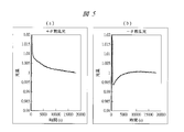
- FIGS. 5A and 5B are graphs showing the measurement results of ⁇ ⁇ scattered light alone after startup of the automatic analyzer. That is, it is the result of measuring the scatterer in the reaction container for 5 hours after starting the device.
- the light amount data of ⁇ ⁇ both decrease greatly, which is due to the drift of the LED light source having the characteristic that the light amount decreases as the temperature rises.
- the light quantity data of ⁇ ⁇ shows the opposite behavior, which is considered to be a drift of the light quantity data due to thermal deformation. Therefore, as shown in FIG.
- drift due to thermal deformation can be corrected at the time of analysis, that is, at the time of calculation of the concentration of the substance to be measured.
- drift correction may be performed based on the sum, or drift correction may be performed using both the average and the sum.
- the average of the light amount data of ⁇ ⁇ also slightly fluctuates, which is a drift of the light source and the electrical circuit system.
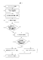
- FIG. 7 (a) to 7 (j) are operation flow diagrams of the light quantity data drift check before the start of analysis by the automatic analyzer of the present invention.
- This function is automatically executed before analysis, for example, at the time of initialization operation after startup of the apparatus, or at the time of bath water replacement (temporary maintenance device 13 is temporarily stopped).
- the computer 50 checks (calculates) whether drift due to thermal deformation of the optical system or drift of the light source and the electrical circuit system within a predetermined measurement time (for example, 5 minutes) falls within a predetermined range (e). If the values are within the predetermined range, the device shifts to the standby state (f). If the values are out of the predetermined range, the measurement is performed again (g). At this time, the drift due to the thermal deformation of the optical system can be calculated by the scattered light amount ratio of ⁇ ⁇ or the scattered light amount difference of ⁇ ⁇ , and the drift of the light source and the electric circuit system can be calculated by the average or sum of the scattered light amounts of ⁇ ⁇ . Then, the computer 50 confirms whether it falls within the predetermined range (h).
- a predetermined measurement time for example, 5 minutes
- the drift check is completed (j).
- the number of remeasurements can be set arbitrarily.
- the purpose of this function is to perform an optical system drift check prior to the start of analysis to determine if it can be measured. In the conventional automatic analyzer, the analysis has been started after starting the apparatus or after a predetermined time, for example, 30 minutes, has elapsed after replacement of the constant temperature bath water.
- This fixed time is the time required for the drift of the optical system to be within the tolerance range, and although it is the time experimentally confirmed, it has not been checked whether the drift has actually converged.
- highly reliable and highly sensitive detection can be realized.
- the analysis items include 1 reagent system, 2 reagent systems, 3 reagent systems, etc.
- items of 2 reagent systems (using the first reagent and the second reagent) will be described as an example.
- the first reagent does not cause a change in light amount even if it is mixed with the sample with the pretreatment reagent, but the second reagent contains latex particles sensitized with an antibody.
- the sample contains the target antigen, aggregation of latex particles occurs due to the antigen-antibody reaction, which causes a change in light intensity.
- the change in light quantity is detected to quantify the concentration of the target substance.
- This example is described on the above premise.
- a sample is first dispensed into a predetermined reaction vessel (b).
- the first reagent (R1) is dispensed and stirred (c).
- the drift due to thermal deformation of the optical system is calculated from the scattered light amount ratio of ⁇ ⁇ and the scattered light amount difference of ⁇ ⁇ from the light amount data acquired while the reaction disk 10 is rotating, and the average or sum of the scattered light amounts of ⁇ ⁇
- the drift of the light source and the electrical circuitry is calculated (d).
- the computer 50 checks whether the values are within the predetermined range (e), and if it is out of the predetermined range, an unmeasurable alarm is sounded (f) and re-measurement (g). If it is within the predetermined range, the computer 50 calculates the average or sum of the scattering of ⁇ ⁇ to generate data on the information of the reaction process (h). Subsequently, the second reagent (R2) is dispensed into the reaction vessel and stirred (i). Similarly, from the light amount data acquired while the reaction disk 10 is rotating, the drift due to the thermal deformation of the optical system is calculated from the scattered light amount ratio of ⁇ ⁇ and the scattered light amount difference of ⁇ ⁇ .
- the computer 50 checks whether these values are within the predetermined range (j), and if it is outside the predetermined range, an unmeasurable alarm is sounded (f) and re-measurement (g). If it is within the predetermined range, the average and sum are calculated by the computer 50 to generate data on information on the reaction process (k), concentration calculation of the substance to be measured is performed (l), the result is output and analysis is performed Finish (m).
- drift check of the optical system was not performed during analysis, but by performing drift check of the optical system during analysis in this way, highly reliable detection and measurement with high reliability It is possible to guarantee the result.
- the present invention is not limited to an embodiment and can be variously changed in the range which does not deviate from the gist. Needless to say.
- the scattered light detectors are arranged in a pair symmetrically in the vertical direction across the optical axis, but the invention is not limited to this, and four or more, that is, two or more It is also good.
- the present invention is applicable to an automatic analyzer and an automatic analysis method for analyzing the amount of components contained in a sample such as blood and urine.
Landscapes
- Analytical Chemistry (AREA)
- General Health & Medical Sciences (AREA)
- Physics & Mathematics (AREA)
- Health & Medical Sciences (AREA)
- Life Sciences & Earth Sciences (AREA)
- Chemical & Material Sciences (AREA)
- Pathology (AREA)
- Biochemistry (AREA)
- Immunology (AREA)
- General Physics & Mathematics (AREA)
- Engineering & Computer Science (AREA)
- Quality & Reliability (AREA)
- Investigating Or Analysing Materials By Optical Means (AREA)
- Automatic Analysis And Handling Materials Therefor (AREA)
- Investigating Or Analysing Materials By The Use Of Chemical Reactions (AREA)
Abstract
装置の大型化および複雑化を伴うことなく、装置内部の温度変動に起因する光学系の熱変形による光量データの変動を補正し、測定対象物質の高感度な検出ができる自動分析装置である。測定対象物質からの散乱光は、受光窓43を通過して、光軸を中心として垂直方向に等角度または等間隔に対称配置された+θ散乱光用検知器45aおよび-θ散乱光用検知器45bにて受光される。光源40は、光源ホルダ(光源が配置されるベース部材)46により固定され、検知器45a、45bは検知器ホルダ(各検知器が配置されるベース部材)47に配置されて固定される。これにより、各検知器45a、45bからの光量データの値を比較することで光学系の熱変形による光量データのドリフトを補正することが可能となる。
Description
本発明は血液や尿などの試料に含まれる成分量を分析する自動分析装置に関し、特に光学系の熱変形によるドリフトの補正が可能な技術である。
試料に含まれる成分量を分析する分析装置として、光源からの光を、試料、または試料と試薬とが混合した反応液に照射し、その結果得られる単一または複数の波長の透過光量を測定し吸光度を算出して、Lambert-Beerの法則にしたがい、吸光度と濃度の関係から成分量を割り出す自動分析装置が広く用いられている(特許文献1参照)。
これらの装置においては、回転と停止を繰り返す反応ディスクに、反応液を保持する多数の反応容器が円周状に並べられ、反応ディスク回転中に、予め配置された透過光測定部により、約10分間、一定の時間間隔で吸光度の経時変化が測定される。測定終了後、反応容器は洗浄機構により洗浄されて、再び分析に使用される。
反応液の反応には、基質と酵素との呈色反応と、抗原と抗体との凝集反応の大きく2種類の反応が用いられる。
前者は生化学分析であり、検査項目としてLDH(乳酸脱水素酵素)、ALP(アルカリホスファターゼ)、AST(アスパラギン酸アミノトランスフェナーゼ)などがある。後者は免疫分析であり、検査項目としてCRP(C反応性蛋白)、IgG(免疫グロブリン)、RF(リウマトイド因子)などがある。
後者の免疫分析で測定される測定物質は血中濃度が低いため高感度な検出系が要求される。例えば、ラテックス粒子の表面に抗体を感作(結合)させた試薬を用い、試料中に含まれる抗原との抗原抗体反応によりラテックス粒子を凝集させる際に、反応液に光を照射し、ラテックス凝集塊に散乱されずに透過した光量を測定することでサンプル中に含まれる成分量を定量するラテックス凝集法での高感度化が図られてきた。
さらに自動分析装置としては、透過光量を測定するのではなく、散乱光量を測定することによる高感度化も試みられている。
ところで、高感度化においては、装置内温度のわずかな変動に起因するような光量データのドリフトも、ごく微小な光量変化を高感度検出する際には大きな障害となる。光量データのドリフトには大きく分類して、(1)光源のドリフト、(2)電気回路系のドリフト、(3)光学系の熱変形によるドリフトが考えられる。(1)光源のドリフトについては、照射光量をモニタして補正する技術(特許文献2参照)が知られており、(2)電気回路系のドリフトについては、回路基板収納庫を温度制御することにより回路由来のドリフトを抑制する技術(特許文献3参照)が知られている。
しかしながら、特許文献2および3の提案は、いずれも、(3)光学系の熱変形によるドリフトを考慮したものではない。
光学系の熱変形は、光度計の熱変形のみならず、光度計が搭載されている機構ベースの熱変形にも影響され、それらの熱変形はそれぞれ個別に動作制御された熱源(モータや基板や熱交換器など)と外気温との複雑な温度変化に影響されるため、コントロールは非常に困難である。さらに、反応ディスクを回転させながら測定を行うターンテーブル方式の自動分析装置において、光度計は反応容器が通過する領域を切り欠いた形状にならざるを得ず、熱変形に対しては不利な形状である。
ここで、例えば、光度計を収納して温度調節する収納庫を備えるようにして、熱源等の影響が及ばないようにすることも考えられる。しかし、新たな装備を加えたのでは、装置を大型化および複雑化してしまうことになる。
本発明の目的は、装置の大型化および複雑化を伴うことなく、装置内部の温度変動に起因する光学系の熱変形による光量データの変動を補正し、測定対象物質の高感度な検出ができる自動分析装置を提供することにある。
本発明の前記ならびにその他の目的と新規な特徴は、本明細書の記述および添付図面から明らかになるであろう。
本願において開示される発明のうち、代表的なものの概要を簡単に説明すれば、次のとおりである。
代表的な実施の形態による自動分析装置は、測光位置に配置されるとともに試料と試薬との混合液を収容する反応容器に光を照射する光源と、前記混合液からの散乱光または透過光を検出する検知器とを備えた自動分析装置であって、前記検知器は前記光源からの照射光の光軸を中心として垂直方向に対称に1組以上配置され、各検知器からの光量データを平均化した値および/または和を、前記混合液内の測定対象物質濃度の算出に用いる。
また、代表的な実施の形態による自動分析装置は、測光位置に配置されるとともに試料と試薬との混合液を収容する反応容器に光源より光を照射し、前記混合液からの散乱光または透過光を検知器により検出して光量データを得て、その光量データから前記混合液内の測定対象物質濃度を算出する自動分析装置であって、前記検知器を前記光源からの照射光の光軸を中心として対称に1組以上配置し、各検知器からの光量データの比および/または差が予め設定した範囲から外れた場合は、前記光量データを前記測定対象物質濃度の算出に用いない。
また、他の代表的な実施の形態による自動分析装置は、測光位置に配置されるとともに試料と試薬との混合液を収容する反応容器に光源より光を照射し、前記混合液からの散乱光または透過光を検知器により検出して光量データを得て、その光量データから前記混合液内の測定対象物質濃度を算出する自動分析装置であって、前記検知器を前記光源からの照射光の光軸を中心として垂直方向に対称に1組以上配置するとともに、前記測光位置に測定対象物質濃度算出用の基準物質を収容した前記反応容器を配置し、各検知器からの前記基準物質の光量データの予め設定した時間におけるドリフト量を、前記測定対象物質濃度の算出に先立って算出しておく。
本願において開示される発明のうち、代表的なものによって得られる効果を簡単に説明すれば以下のとおりである。
本発明によれば、反応容器からの散乱光または透過光を検出する検知器を光源からの照射光の光軸を中心として対称に1組以上配置したので、各検知器からの光量データの値を比較することで光学系の熱変形による光量データのドリフトを補正することが可能となる。したがって、装置の大型化や複雑化を伴うことなく、装置内部の温度変動に起因する光学系の熱変形による光量データのドリフトを補正し、データの正確性や安定性を高め、測定対象物質の高感度な検出が可能な自動分析装置を提供できる。
以下、本発明の実施の形態を図面に基づいて詳細に説明する。なお、本実施の形態を説明するための全図において同一機能を有するものは原則として同一の符号を付すようにし、その繰り返しの説明は可能な限り省略するようにしている。
図1は、本発明の一実施の形態である自動分析装置の全体構成を示すシステムブロック図である。図1に示すように、自動分析装置1は、主に、反応ディスク10、サンプルディスク20、試薬ディスク30a、30b、光源40、散乱光度計41およびコンピュータ50から構成されている。
反応ディスク10は、間欠回転可能に設けられており、ディスク上に透光性材料からなる多数の反応容器11が周方向に沿って装着されている。反応容器11は、恒温槽12により所定温度(例えば37℃)に維持されている。恒温槽12内の流体は、恒温維持装置13により温度調整されている。
サンプルディスク20上には、血液、尿等の生体サンプルを収容する多数の検体容器21が、図示の例では二重に、周方向に沿って載置されている。また、サンプルディスク20の近傍には、サンプル分注機構22が配置されている。このサンプル分注機構22は、可動アーム23と、これに取り付けられたピペットノズル24とから主に構成されている。この構成により、サンプル分注機構22は、サンプル分注時にはピペットノズル24が可動アーム23により分注位置に適宜移動して、サンプルディスク20の吸入位置に位置する検体容器21から所定量のサンプルを吸入し、そのサンプルを反応ディスク10上の吐出位置にある反応容器11内に吐出する。
試薬ディスク30a、30bは、互いに概ね同径かつ同形状のディスクであり、試薬保冷庫31a、31bがそれぞれ周方向に沿って配置されている。この試薬保冷庫31a、31bには、バーコードのように試薬識別情報を表示したラベルが貼られた複数の試薬ボトル32a、32bが、試薬ディスク30a、30bの周方向に沿ってそれぞれ載置されている。これらの試薬ボトル32a、32bには、自動分析装置1により分析され得る分析項目に対応する試薬液が収容されている。また、各試薬保冷庫31a、31bは、バーコード読み取り装置33a、33bが付属されており、これらの装置が試薬登録時に各試薬ボトル32a、32bの外壁に表示されているバーコードを読み取る。読み取られた試薬情報は、試薬ディスク30a、30b上のポジションとともにメモリ56に登録される。
また、試薬ディスク30a、30bの近傍には、サンプル分注機構22と概ね同様の機構をなす試薬分注機構34a、34bがそれぞれ配置されている。試薬分注時には、これらが備えるピペットノズルにより、反応ディスク10上の試薬受け入れ位置に位置付けられる検査項目に応じた試薬ボトル32a、32bから試薬液を吸入し、該当する反応容器11内へ吐出する。
反応ディスク10、試薬ディスク30a、30bおよび試薬分注機構34a、34bに囲まれる位置には、攪拌機構35a、35bが配置されている。反応容器11内に収容されたサンプルと試薬との混合液は、この攪拌機構35a、35bにより攪拌されて反応が促進される。
ここで、光源40は反応ディスク10の中心部付近に、散乱光度計41は反応ディスク10の外周側に配置されており、攪拌を終えた反応容器11の列は光源40と散乱光度計41とによって挟まれた測光位置を通るように回転移動する。散乱光度計41は同軸光軸上、または恒温槽12の別ポジションに多波長吸光光度計を備えてもよく、散乱光と透過光の両方を使って濃度演算を行ってもよい。なお、光源40と散乱光度計41は光検出系を構成する。
各反応容器11内におけるサンプルと試薬との反応液は、反応ディスク10の回転動作中に散乱光度計41の前を横切る度に測光される。サンプル毎に測定された散乱光のアナログ信号は、A/D(アナログ/ディジタル)変換器54に入力される。使用済みの反応容器11は、反応ディスク10の近傍に配置された反応容器洗浄機構36により、内部が洗浄されて繰り返しの使用を可能にする。
次に、図1の自動分析装置1における制御系及び信号処理系について簡単に説明する。コンピュータ50は、インターフェース51を介して、サンプル分注制御部52、試薬分注制御部53、A/D変換器54に接続されている。コンピュータ50は、サンプル分注制御部52に対して指令を送り、サンプルの分注動作を制御する。また、コンピュータ50は、試薬分注制御部53に対して指令を送り、試薬の分注動作を制御する。
A/D変換器54によってディジタル信号に変換された測光値は、コンピュータ50に取り込まれる。
インターフェース51には、印字するためのプリンタ55、記憶装置であるメモリ56や外部出力メディア57、操作指令等を入力するためのキーボード58、画面表示するためのCRTディスプレイ(表示装置)59が接続されている。表示装置59としては、CRTディスプレイの他に液晶ディスプレイなどを採用できる。メモリ56は、例えばハードディスクメモリまたは外部メモリにより構成される。メモリ56には、各操作者のパスワード、各画面の表示レベル、分析パラメータ、分析項目依頼内容、キャリブレーション結果、分析結果等の情報が記憶される。
次に、図1の自動分析装置1におけるサンプルの分析動作を説明する。自動分析装置1によって分析可能な項目に関する分析パラメータは、予めキーボード58等の情報入力装置を介して入力されておリ、メモリ56に記憶されている。操作者は、操作機能画面を用いて各サンプルに依頼されている検査項目を選択する。
この際に、患者IDなどの情報もキーボード58から入力される。各サンプルに対して指示された検査項目を分析するために、サンプル分注機構22のピペットノズル24は、分析パラメータにしたがって、検体容器21から反応容器11へ所定量のサンプルを分注する。
サンプルが分注された反応容器11は、反応ディスク10の回転によって移送され、試薬受け入れ位置に停止する。試薬分注機構34a、34bのピペットノズルは、該当する検査項目の分析パラメータにしたがって、反応容器11に所定量の試薬液を分注する。サンプルと試薬の分注順序は、この例とは逆に、サンプルより試薬が先であってもよい。
その後、攪拌機構35a、35bにより、サンプルと試薬との攪拌が行われ、混合される。この反応容器11が、測光位置を横切る時、散乱光度計41により反応液の散乱光が測光される。測光された散乱光は、A/D変換器54により光量に比例した数値に変換され、インターフェース51を経由して、コンピュータ50に取り込まれる。
この変換された数値を用い、検査項目毎に指定された分析法により予め測定しておいた検量線に基づき、濃度データが算出される。各検査項目の分析結果としての成分濃度データは、プリンタ55やCRTディスプレイ59の画面に出力される。
以上の測定動作が実行される前に、操作者は、分析測定に必要な種々のパラメータの設定や試料の登録を、CRTディスプレイ59の操作画面を介して行う。また、操作者は、測定後の分析結果をCRTディスプレイ59上の操作画面により確認する。
図2は、本発明の一実施の形態における光学系の概略図である。光源40からの照射光は、投光窓42を通過して、反応容器11内の測定対象物質に照射される。測定対象物質からの透過光は、受光窓43を通過して透過光用検知器44にて受光される。測定対象物質からの散乱光は、受光窓43を通過して、光軸を中心として垂直方向に対称配置された1組の+θ散乱光用検知器45aおよび-θ散乱光用検知器45bにて受光される。光源40は、光源ホルダ(光源が配置されるベース部材)46により固定され、検知器44、45a、45bは検知器ホルダ(各検知器が配置されるベース部材)47に等間隔に配置されて固定される。光源ホルダ46と検知器ホルダ47は、光度計ベース48に固定され、光度計ベース48は機構ベース49に固定される。モータ、回路、熱交換器等の動作により、装置内の温度分布は変化するが、特に装置立ち上げ直後の温度変化は大きく、装置上下の温度差により矢印で示したような変形が生じることとなる。ターンテーブル方式における光度計は、反応容器11が通過できるように上方が開いた形状となっているため、矢印に示したような変形が生じやすい。変形する部位としては、寸法的な違いから、光度計ベース48、機構ベース49の変形量が大きく、光源ホルダ46、検知器ホルダ47の変形量は小さい。したがって、図3に示すように、受光角度の相対的位置関係は保ったまま、δ°だけずれるような変形が生じる。
図4は、受光角度変化による±θ散乱光の光量変化の測定結果を示すグラフである。つまり、ある受光角度θの相対位置関係を保持したまま、検知器ホルダ47の角度を変更したときの光量データの変動を実測した結果である。±θの散乱光は理論的に同じ値になるはずで、本結果も受光角度のずれが無い場合、値は概ね一致した。受光角度のずれと光量データとの間には比例関係が見られ、±θの光量データの和は一定になることがわかる。つまり、±θの光量データの和または平均、あるいはその両方をとることで、熱変形に由来する光量データのドリフトを補正できる可能性を見出した。
光量データのドリフトには大きく分類して、(1)光源のドリフト、(2)電気回路系のドリフト、(3)光学系の熱変形によるドリフトが考えられる。これらのうち、(1)光源のドリフト、(2)電気回路系のドリフトは、光源や電気回路の温調対策により、ある一定レベルに押さえることが容易である。しかしながら、(3)光学系の熱変形によるドリフトは、光度計の変形のみならず、光度計が搭載されているベースの変形にも影響される。さらには、モータや基板や熱交換器などのそれぞれ個別に動作制御された熱源と外気温との複雑な温度変化にも影響される。そのため、コントロールは非常に困難であり、補正できることの意味は大きい。
図5(a)、(b)は、それぞれ自動分析装置立ち上げ後の±θ散乱光単独の測定結果を示すグラフである。つまり、装置を立ち上げてから5時間、反応容器内の散乱体を測定した結果である。装置立ち上げ直後は、±θの光量データは共に大きく低下しているが、これは温度が上がると光量が低下する特性を持つLED光源のドリフトによる。光源のドリフトが概ね解消されると、±θの光量データは逆の挙動を示すが、これは熱変形による光量データのドリフトと考えられる。そこで、図6に示すように、±θの光量データの平均をとることで、分析時、つまり測定対象物質濃度の算出時に、熱変形によるドリフトを補正できる。なお、図6の例では±θの光量データの平均であるが、その和に基づきドリフト補正をしてもよいし、平均と和との両者を用いてドリフト補正をしてもよい。図6をみると、±θの光量データの平均もわずかに変動しているが、これは光源および電気回路系のドリフトである。
図7(a)~(j)は、本発明の自動分析装置による分析開始前の光量データドリフトチェックの動作フロー図である。本機能は、分析前、例えば装置立ち上げ後のイニシャライズ動作時や、恒温槽水交換時(一時的に恒温維持装置13が停止する)に、自動的に実行される。まず、ドリフトチェックが開始されると(a)、所定の反応容器にブランク水またはブランク液などの測定対象物質濃度算出用の基準物質が分注され(b)、続いて当該反応容器は測光位置に移動される(c)。当該反応容器の移動後、その反応容器を停止させた状態で散乱光や透過光の測定が実施される(d)。既定の測定時間(例えば、5分間)における光学系の熱変形によるドリフトや、光源および電気回路系のドリフトが、既定の範囲内に収まっているかをコンピュータ50が確認(算出)する(e)。それらの値が既定範囲内であれば、装置はスタンバイ状態に移行し(f)、既定範囲外であれば、再度測定を実施する(g)。このとき、±θの散乱光量比や±θの散乱光量差によって光学系の熱変形によるドリフトが算出でき、±θの散乱光量の平均や和によって光源および電気回路系のドリフトが算出できる。そして、既定の範囲内に収まっているかをコンピュータ50が確認する(h)。再度測定しても、±θの散乱光量比や、±θの散乱光量差、透過光や散乱光単独のドリフト量が、既定の範囲外である場合は、分析不可アラームを鳴らし、分析動作(測定対象物質濃度の算出)に移行できないようにする(i)。以上によりドリフトチェックを終了する(j)。再測定回数は任意に設定可能である。この機能の目的は、分析開始前に光学系のドリフトチェックを行い、測定可能かどうか判断することである。これまでの自動分析装置では、装置立ち上げ後、または恒温槽水交換後の一定時間、例えば30分経過後に分析を開始するような運用になっていた。この一定時間は、光学系のドリフトが許容範囲内に収まるのに必要な時間で、実験的に裏づけがとられた時間ではあるが、実際にドリフトが収束したかどうかのチェックは行ってはいなかった。しかし、分析前のドリフトチェックを行うことで、信頼性の高い高感度な検出が実現できる。
図8(a)~(m)は、本発明の自動分析装置による分析中の光量データドリフトチェックの動作フロー図である。分析項目には、1試薬系、2試薬系、3試薬系など存在するが、本実施例は2試薬系(第1試薬と第2試薬を使用する)の項目を例として記載する。また、一般的にラテックス凝集法では、第1試薬は前処理用試薬で試料と混合しても光量変化等は起こさないが、第2試薬は抗体が感作されたラテックス粒子が含まれており、試料に対象とする抗原が含まれる場合に抗原抗体反応によるラテックス粒子の凝集が起こり、光量変化を起こす。この光量変化を検出して、対象物質の濃度を定量する。上記前提において、本実施例を記載する。分析が開始されたならば(a)、所定の反応容器に、まず試料が分注される(b)。次いで、第1試薬(R1)が分注され、攪拌される(c)。反応ディスク10が回転中に取得される光量データから、±θの散乱光量比や、±θの散乱光量差から光学系の熱変形によるドリフトが算出され、±θの散乱光量の平均や和によって光源および電気回路系のドリフトが算出される(d)。それらの値が既定範囲内にあるかコンピュータ50が確認し(e)、既定範囲外であれば測定不可アラームを鳴らし(f)、再測定する(g)。既定範囲内であれば、コンピュータ50により±θの散乱の平均や和を算出し、反応過程の情報に関するデータを生成する(h)。引き続いて当該反応容器には第2試薬(R2)が分注され、攪拌される(i)。同様に、反応ディスク10が回転中に取得される光量データから、±θの散乱光量比や、±θの散乱光量差から光学系の熱変形によるドリフトが算出される。それらの値が既定範囲内にあるかコンピュータ50が確認し(j)、既定範囲外であれば測定不可アラームを鳴らし(f)、再測定する(g)。既定範囲内であれば、コンピュータ50によりの平均や和を算出し反応過程の情報に関するデータを生成し(k)、測定対象物質の濃度演算が行われ(l)、結果が出力されて分析を終了する(m)。従来の自動分析装置においては、分析中に光学系のドリフトチェックを行っていなかったが、このように分析中に光学系のドリフトチェックを行うことで、信頼性の高い高感度な検出と、測定結果の保証が可能となる。
以上、本発明者によってなされた発明を、実施の形態に基づき具体的に説明したが、本発明は実施の形態に限定されるものではなく、その要旨を逸脱しない範囲で種々変更可能であることはいうまでもない。
例えば、図示した形態では、散乱光用検知器は光軸を挟んで垂直方向に対称に2個1組で配置されているが、これに限らず、4個以上、つまり2組以上配置してもよい。
本発明は、血液や尿などの試料に含まれる成分量を分析する自動分析装置および自動分析方法に利用可能である。
1 自動分析装置
10 反応ディスク
11 反応容器
12 恒温槽
13 恒温維持装置
20 サンプルディスク
21 検体容器
22 サンプル分注機構
23 可動アーム
24 ピペットノズル
30a 試薬ディスク
30b 試薬ディスク
31a 試薬保冷庫
31b 試薬保冷庫
32a 試薬ボトル
32b 試薬ボトル
33a バーコード読み取り装置
33b バーコード読み取り装置
34a 試薬分注機構
34b 試薬分注機構
35a 攪拌機構
35b 攪拌機構
36 反応容器洗浄機構
40 光源
41 散乱光度計
42 投光窓
43 受光窓
44 透過光用検知器
45a +θ散乱光用検知器
45b -θ散乱光用検知器
46 光源ホルダ(光源が配置されるベース部材)
47 検知器ホルダ(各検知器が配置されるベース部材)
48 光度計ベース
49 機構ベース
50 コンピュータ
51 インターフェース
52 サンプル分注制御部
53 試薬分注制御部
54 A/D変換器
55 プリンタ
56 メモリ
57 外部出力メディア
58 キーボード
59 CRTディスプレイ(表示装置)
Claims (9)
- 測光位置に配置されるとともに試料と試薬との混合液を収容する反応容器に光を照射する光源と、前記混合液からの散乱光または透過光を検出する検知器とを備えた自動分析装置であって、
前記検知器は前記光源からの照射光の光軸を中心として等角度または等間隔に対称に1組以上配置され、各検知器からの光量データを平均化した値および/または和を、前記混合液内の測定対象物質濃度の算出に用いることを特徴とする自動分析装置。 - 請求項1に記載の自動分析装置において、1組以上の前記検知器は同一のベース部材上に配置され、かつ、その同一のベース部材上に各検知器が光軸を中心として等角度または等間隔に対称に配置されることを特徴とする自動分析装置。
- 請求項2に記載の自動分析装置において、さらに、各検知器が配置される前記ベース部材と前記光源が配置されるベース部材とが同一のベース上に配置されることを特徴とする自動分析装置。
- 請求項3に記載の自動分析装置において、
前記光源からの照射光の光軸を中心として等角度または等間隔に対称に配置された各検知器からの光量データの比および/または差が予め設定した範囲から外れた場合は、前記光量データを前記測定対象物質濃度の算出に用いないことを特徴とする自動分析装置。 - 請求項3または4に記載の自動分析装置において、
前記光源からの照射光の光軸を中心として等角度または等間隔に対称に配置された各検知器からの光量データを平均化した値および/または和が予め設定した範囲から外れた場合は、前記光量データを前記測定対象物質濃度の算出に用いないことを特徴とする自動分析装置。 - 請求項4または5に記載の自動分析装置において、
前記光源からの照射光の光軸を中心として等角度または等間隔に対称に1組以上配置するとともに、前記測光位置に測定対象物質濃度算出用の基準物質を収容した前記反応容器を配置し、各検知器からの前記基準物質の光量データの予め設定した時間におけるドリフト量を、前記測定対象物質濃度の算出に先立って算出しておくことを特徴とする自動分析装置。 - 請求項6に記載の自動分析装置において、前記ドリフト量が予め設定した範囲を外れていた場合には前記測定対象物質濃度の算出に移行しないことを特徴とする自動分析装置。
- 請求項7に記載の自動分析装置において、前記ドリフト量は、各検出器からの光量データの比および/または差であることを特徴とする自動分析装置。
- 請求項7または8に記載の自動分析装置において、
前記ドリフト量は、各検出器からの光量データを平均化した値および/または和であることを特徴とする自動分析装置。
Priority Applications (3)
| Application Number | Priority Date | Filing Date | Title |
|---|---|---|---|
| US13/979,668 US9080972B2 (en) | 2011-01-17 | 2012-01-10 | Automatic analyzer |
| CN201280004143.9A CN103261876B (zh) | 2011-01-17 | 2012-01-10 | 自动分析装置 |
| EP12736834.8A EP2667182B1 (en) | 2011-01-17 | 2012-01-10 | Automatic analysis device taking into account thermal drift |
Applications Claiming Priority (2)
| Application Number | Priority Date | Filing Date | Title |
|---|---|---|---|
| JP2011006809A JP5481402B2 (ja) | 2011-01-17 | 2011-01-17 | 自動分析装置 |
| JP2011-006809 | 2011-01-17 |
Publications (1)
| Publication Number | Publication Date |
|---|---|
| WO2012098946A1 true WO2012098946A1 (ja) | 2012-07-26 |
Family
ID=46515577
Family Applications (1)
| Application Number | Title | Priority Date | Filing Date |
|---|---|---|---|
| PCT/JP2012/050243 WO2012098946A1 (ja) | 2011-01-17 | 2012-01-10 | 自動分析装置 |
Country Status (5)
| Country | Link |
|---|---|
| US (1) | US9080972B2 (ja) |
| EP (1) | EP2667182B1 (ja) |
| JP (1) | JP5481402B2 (ja) |
| CN (1) | CN103261876B (ja) |
| WO (1) | WO2012098946A1 (ja) |
Cited By (3)
| Publication number | Priority date | Publication date | Assignee | Title |
|---|---|---|---|---|
| JP2014137319A (ja) * | 2013-01-18 | 2014-07-28 | Hitachi High-Technologies Corp | 自動分析装置 |
| WO2014203741A1 (ja) * | 2013-06-19 | 2014-12-24 | 株式会社日立ハイテクノロジーズ | 自動分析装置及び自動分析方法 |
| WO2016006362A1 (ja) * | 2014-07-07 | 2016-01-14 | 株式会社 日立ハイテクノロジーズ | 自動分析装置 |
Families Citing this family (7)
| Publication number | Priority date | Publication date | Assignee | Title |
|---|---|---|---|---|
| JP5897323B2 (ja) * | 2011-12-26 | 2016-03-30 | 株式会社日立ハイテクノロジーズ | 自動分析装置および測定値異常検出方法 |
| JP6138564B2 (ja) * | 2013-04-18 | 2017-05-31 | 株式会社日立ハイテクノロジーズ | 自動分析装置 |
| CN103884856B (zh) * | 2014-04-01 | 2015-06-10 | 重庆科斯迈生物科技有限公司 | 化学发光免疫分析仪杯条运送系统 |
| CN110785650B (zh) | 2017-06-20 | 2022-05-31 | Ci系统(以色列)股份有限公司 | 用于分析流体的流通池以及光学系统 |
| US11965900B2 (en) * | 2018-11-09 | 2024-04-23 | Wyatt Technology, Llc | Indicating a status of an analytical instrument on a screen of the analytical instrument |
| CN109613284B (zh) * | 2018-11-19 | 2023-02-28 | 圣湘生物科技股份有限公司 | 样本检测方法、装置以及系统、计算机设备和存储介质 |
| WO2022270037A1 (ja) * | 2021-06-25 | 2022-12-29 | 古野電気株式会社 | 測光装置および分析装置 |
Citations (7)
| Publication number | Priority date | Publication date | Assignee | Title |
|---|---|---|---|---|
| US4451433A (en) | 1980-11-10 | 1984-05-29 | Hitachi, Ltd. | Automatic chemical analyzer |
| JPS6182143A (ja) * | 1984-06-20 | 1986-04-25 | ペンロン リミテツド | ガス分析装置及びガス分析方法 |
| JPH0545282A (ja) * | 1991-08-09 | 1993-02-23 | Kurabo Ind Ltd | 自動臨床分析システム |
| JP2002296283A (ja) | 2001-04-02 | 2002-10-09 | Hitachi Ltd | 自動分析装置 |
| JP2007322246A (ja) | 2006-05-31 | 2007-12-13 | Olympus Corp | 自動分析装置 |
| WO2010073604A1 (ja) * | 2008-12-24 | 2010-07-01 | 株式会社日立ハイテクノロジーズ | 光度計及び光度計を備えた分析システム |
| WO2011004781A1 (ja) * | 2009-07-10 | 2011-01-13 | 株式会社日立ハイテクノロジーズ | 自動分析装置 |
Family Cites Families (19)
| Publication number | Priority date | Publication date | Assignee | Title |
|---|---|---|---|---|
| JPS591977B2 (ja) * | 1978-01-25 | 1984-01-14 | 株式会社京都第一科学 | 呈色試験紙を用いた分析方法 |
| SE7905294L (sv) * | 1979-06-15 | 1980-12-16 | Svenska Traeforskningsinst | Stoftmetning |
| US4408880A (en) * | 1981-09-22 | 1983-10-11 | Chugai Seiyaku Kabushiki Kaisha | Laser nephelometric system |
| US5363463A (en) * | 1982-08-06 | 1994-11-08 | Kleinerman Marcos Y | Remote sensing of physical variables with fiber optic systems |
| JPS61173138A (ja) * | 1985-01-28 | 1986-08-04 | Olympus Optical Co Ltd | 光強度ゆらぎによる免疫反応測定方法 |
| JPS62291547A (ja) * | 1986-06-11 | 1987-12-18 | Olympus Optical Co Ltd | 物質の濃度測定方法 |
| US5350922A (en) * | 1993-03-22 | 1994-09-27 | Robert Bartz | Underwater light scattering sensor |
| JP3600929B2 (ja) * | 1996-10-17 | 2004-12-15 | 東ソー株式会社 | ポリ塩化ビニルのゲル化度の測定方法及び測定装置 |
| US6574425B1 (en) * | 1997-10-31 | 2003-06-03 | Jack L. Aronowitz | Reflectometer |
| US6519033B1 (en) * | 2001-11-19 | 2003-02-11 | Point Source Technologies, Llc | Identification of particles in fluid |
| JP3765255B2 (ja) * | 2001-08-21 | 2006-04-12 | 株式会社日立製作所 | 攪拌装置およびそれを用いた自動分析装置 |
| JP2003294623A (ja) * | 2002-03-29 | 2003-10-15 | Nohmi Bosai Ltd | 煙火災感知器 |
| CA2468924A1 (en) * | 2004-01-14 | 2005-07-14 | Laser Diagnostic Instruments International Inc. | A device and method for non-contact sensing of low-concentration and trace substances |
| US7111496B1 (en) * | 2004-04-29 | 2006-09-26 | Pedro Lilienfeld | Methods and apparatus for monitoring a mass concentration of particulate matter |
| JP4756948B2 (ja) * | 2005-08-08 | 2011-08-24 | ベイバイオサイエンス株式会社 | フローサイトメータおよびフローサイトメトリ方法 |
| US7678330B2 (en) * | 2006-03-01 | 2010-03-16 | Aleksandr Ostrovsky | System, method and apparatus for use in blood testing through luminescence |
| JP2008064594A (ja) * | 2006-09-07 | 2008-03-21 | Yokogawa Electric Corp | 濁度計 |
| CN101403706B (zh) * | 2008-11-06 | 2011-06-08 | 清华大学 | 全自动瓶装药液检查机 |
| JP2010197310A (ja) * | 2009-02-26 | 2010-09-09 | Toyota Motor Corp | 光チョッパおよび光学式分析装置 |
-
2011
- 2011-01-17 JP JP2011006809A patent/JP5481402B2/ja active Active
-
2012
- 2012-01-10 CN CN201280004143.9A patent/CN103261876B/zh active Active
- 2012-01-10 EP EP12736834.8A patent/EP2667182B1/en active Active
- 2012-01-10 WO PCT/JP2012/050243 patent/WO2012098946A1/ja active Application Filing
- 2012-01-10 US US13/979,668 patent/US9080972B2/en active Active
Patent Citations (7)
| Publication number | Priority date | Publication date | Assignee | Title |
|---|---|---|---|---|
| US4451433A (en) | 1980-11-10 | 1984-05-29 | Hitachi, Ltd. | Automatic chemical analyzer |
| JPS6182143A (ja) * | 1984-06-20 | 1986-04-25 | ペンロン リミテツド | ガス分析装置及びガス分析方法 |
| JPH0545282A (ja) * | 1991-08-09 | 1993-02-23 | Kurabo Ind Ltd | 自動臨床分析システム |
| JP2002296283A (ja) | 2001-04-02 | 2002-10-09 | Hitachi Ltd | 自動分析装置 |
| JP2007322246A (ja) | 2006-05-31 | 2007-12-13 | Olympus Corp | 自動分析装置 |
| WO2010073604A1 (ja) * | 2008-12-24 | 2010-07-01 | 株式会社日立ハイテクノロジーズ | 光度計及び光度計を備えた分析システム |
| WO2011004781A1 (ja) * | 2009-07-10 | 2011-01-13 | 株式会社日立ハイテクノロジーズ | 自動分析装置 |
Cited By (8)
| Publication number | Priority date | Publication date | Assignee | Title |
|---|---|---|---|---|
| JP2014137319A (ja) * | 2013-01-18 | 2014-07-28 | Hitachi High-Technologies Corp | 自動分析装置 |
| WO2014203741A1 (ja) * | 2013-06-19 | 2014-12-24 | 株式会社日立ハイテクノロジーズ | 自動分析装置及び自動分析方法 |
| JP2015004534A (ja) * | 2013-06-19 | 2015-01-08 | 株式会社日立ハイテクノロジーズ | 自動分析装置及び自動分析方法 |
| CN105209888A (zh) * | 2013-06-19 | 2015-12-30 | 株式会社日立高新技术 | 自动分析装置以及自动分析方法 |
| US9575082B2 (en) | 2013-06-19 | 2017-02-21 | Hitachi High-Technologies Corporation | Automatic analysis device and automatic analysis method |
| CN105209888B (zh) * | 2013-06-19 | 2017-10-24 | 株式会社日立高新技术 | 自动分析装置以及自动分析方法 |
| WO2016006362A1 (ja) * | 2014-07-07 | 2016-01-14 | 株式会社 日立ハイテクノロジーズ | 自動分析装置 |
| JPWO2016006362A1 (ja) * | 2014-07-07 | 2017-04-27 | 株式会社日立ハイテクノロジーズ | 自動分析装置 |
Also Published As
| Publication number | Publication date |
|---|---|
| JP2012149903A (ja) | 2012-08-09 |
| CN103261876B (zh) | 2016-01-13 |
| EP2667182B1 (en) | 2019-09-11 |
| CN103261876A (zh) | 2013-08-21 |
| US20130301048A1 (en) | 2013-11-14 |
| EP2667182A4 (en) | 2017-04-26 |
| JP5481402B2 (ja) | 2014-04-23 |
| US9080972B2 (en) | 2015-07-14 |
| EP2667182A1 (en) | 2013-11-27 |
Similar Documents
| Publication | Publication Date | Title |
|---|---|---|
| WO2012098946A1 (ja) | 自動分析装置 | |
| JP5897323B2 (ja) | 自動分析装置および測定値異常検出方法 | |
| JP6013796B2 (ja) | 自動分析装置及び試料測定方法 | |
| JP5296015B2 (ja) | 自動分析装置 | |
| JP5216051B2 (ja) | 自動分析装置および自動分析方法 | |
| JP5939833B2 (ja) | 自動分析装置 | |
| JP5661124B2 (ja) | 自動分析装置 | |
| JP6104746B2 (ja) | 自動分析装置および分析方法 | |
| JP5487176B2 (ja) | 自動分析装置 | |
| JPWO2017043192A1 (ja) | 自動分析装置 | |
| JP5952180B2 (ja) | 自動分析装置、プログラムおよび記録媒体ならびに検体の自動分析方法 | |
| JP2020041929A (ja) | 自動分析装置 | |
| WO2021024535A1 (ja) | 自動分析装置 | |
| JP2009150693A (ja) | 反応の良否判定方法及び分析装置 |
Legal Events
| Date | Code | Title | Description |
|---|---|---|---|
| 121 | Ep: the epo has been informed by wipo that ep was designated in this application |
Ref document number: 12736834 Country of ref document: EP Kind code of ref document: A1 |
|
| WWE | Wipo information: entry into national phase |
Ref document number: 2012736834 Country of ref document: EP |
|
| WWE | Wipo information: entry into national phase |
Ref document number: 13979668 Country of ref document: US |
|
| NENP | Non-entry into the national phase |
Ref country code: DE |