WO2012093507A1 - Appareil de commutation - Google Patents
Appareil de commutation Download PDFInfo
- Publication number
- WO2012093507A1 WO2012093507A1 PCT/JP2011/069283 JP2011069283W WO2012093507A1 WO 2012093507 A1 WO2012093507 A1 WO 2012093507A1 JP 2011069283 W JP2011069283 W JP 2011069283W WO 2012093507 A1 WO2012093507 A1 WO 2012093507A1
- Authority
- WO
- WIPO (PCT)
- Prior art keywords
- arc
- contact
- extinguishing member
- fixed
- arc extinguishing
- Prior art date
Links
Images


Classifications
-
- H—ELECTRICITY
- H01—ELECTRIC ELEMENTS
- H01H—ELECTRIC SWITCHES; RELAYS; SELECTORS; EMERGENCY PROTECTIVE DEVICES
- H01H33/00—High-tension or heavy-current switches with arc-extinguishing or arc-preventing means
- H01H33/60—Switches wherein the means for extinguishing or preventing the arc do not include separate means for obtaining or increasing flow of arc-extinguishing fluid
- H01H33/64—Switches wherein the means for extinguishing or preventing the arc do not include separate means for obtaining or increasing flow of arc-extinguishing fluid wherein the break is in gas
- H01H33/65—Switches wherein the means for extinguishing or preventing the arc do not include separate means for obtaining or increasing flow of arc-extinguishing fluid wherein the break is in gas wherein the break is in air at atmospheric pressure, e.g. in open air
-
- H—ELECTRICITY
- H01—ELECTRIC ELEMENTS
- H01H—ELECTRIC SWITCHES; RELAYS; SELECTORS; EMERGENCY PROTECTIVE DEVICES
- H01H33/00—High-tension or heavy-current switches with arc-extinguishing or arc-preventing means
- H01H33/02—Details
- H01H33/04—Means for extinguishing or preventing arc between current-carrying parts
- H01H33/12—Auxiliary contacts on to which the arc is transferred from the main contacts
-
- H—ELECTRICITY
- H01—ELECTRIC ELEMENTS
- H01H—ELECTRIC SWITCHES; RELAYS; SELECTORS; EMERGENCY PROTECTIVE DEVICES
- H01H33/00—High-tension or heavy-current switches with arc-extinguishing or arc-preventing means
- H01H33/02—Details
- H01H33/04—Means for extinguishing or preventing arc between current-carrying parts
- H01H33/18—Means for extinguishing or preventing arc between current-carrying parts using blow-out magnet
- H01H33/182—Means for extinguishing or preventing arc between current-carrying parts using blow-out magnet using permanent magnets
-
- H—ELECTRICITY
- H01—ELECTRIC ELEMENTS
- H01H—ELECTRIC SWITCHES; RELAYS; SELECTORS; EMERGENCY PROTECTIVE DEVICES
- H01H33/00—High-tension or heavy-current switches with arc-extinguishing or arc-preventing means
- H01H33/70—Switches with separate means for directing, obtaining, or increasing flow of arc-extinguishing fluid
- H01H33/7015—Switches with separate means for directing, obtaining, or increasing flow of arc-extinguishing fluid characterised by flow directing elements associated with contacts
- H01H33/7023—Switches with separate means for directing, obtaining, or increasing flow of arc-extinguishing fluid characterised by flow directing elements associated with contacts characterised by an insulating tubular gas flow enhancing nozzle
- H01H33/703—Switches with separate means for directing, obtaining, or increasing flow of arc-extinguishing fluid characterised by flow directing elements associated with contacts characterised by an insulating tubular gas flow enhancing nozzle having special gas flow directing elements, e.g. grooves, extensions
-
- H—ELECTRICITY
- H01—ELECTRIC ELEMENTS
- H01H—ELECTRIC SWITCHES; RELAYS; SELECTORS; EMERGENCY PROTECTIVE DEVICES
- H01H33/00—High-tension or heavy-current switches with arc-extinguishing or arc-preventing means
- H01H33/70—Switches with separate means for directing, obtaining, or increasing flow of arc-extinguishing fluid
- H01H33/7015—Switches with separate means for directing, obtaining, or increasing flow of arc-extinguishing fluid characterised by flow directing elements associated with contacts
- H01H33/7038—Switches with separate means for directing, obtaining, or increasing flow of arc-extinguishing fluid characterised by flow directing elements associated with contacts characterised by a conducting tubular gas flow enhancing nozzle
- H01H33/7046—Switches with separate means for directing, obtaining, or increasing flow of arc-extinguishing fluid characterised by flow directing elements associated with contacts characterised by a conducting tubular gas flow enhancing nozzle having special gas flow directing elements, e.g. grooves, extensions
-
- H—ELECTRICITY
- H01—ELECTRIC ELEMENTS
- H01H—ELECTRIC SWITCHES; RELAYS; SELECTORS; EMERGENCY PROTECTIVE DEVICES
- H01H33/00—High-tension or heavy-current switches with arc-extinguishing or arc-preventing means
- H01H33/70—Switches with separate means for directing, obtaining, or increasing flow of arc-extinguishing fluid
- H01H33/88—Switches with separate means for directing, obtaining, or increasing flow of arc-extinguishing fluid the flow of arc-extinguishing fluid being produced or increased by movement of pistons or other pressure-producing parts
- H01H33/90—Switches with separate means for directing, obtaining, or increasing flow of arc-extinguishing fluid the flow of arc-extinguishing fluid being produced or increased by movement of pistons or other pressure-producing parts this movement being effected by or in conjunction with the contact-operating mechanism
- H01H33/91—Switches with separate means for directing, obtaining, or increasing flow of arc-extinguishing fluid the flow of arc-extinguishing fluid being produced or increased by movement of pistons or other pressure-producing parts this movement being effected by or in conjunction with the contact-operating mechanism the arc-extinguishing fluid being air or gas
-
- H—ELECTRICITY
- H01—ELECTRIC ELEMENTS
- H01H—ELECTRIC SWITCHES; RELAYS; SELECTORS; EMERGENCY PROTECTIVE DEVICES
- H01H33/00—High-tension or heavy-current switches with arc-extinguishing or arc-preventing means
- H01H33/70—Switches with separate means for directing, obtaining, or increasing flow of arc-extinguishing fluid
- H01H33/88—Switches with separate means for directing, obtaining, or increasing flow of arc-extinguishing fluid the flow of arc-extinguishing fluid being produced or increased by movement of pistons or other pressure-producing parts
- H01H33/90—Switches with separate means for directing, obtaining, or increasing flow of arc-extinguishing fluid the flow of arc-extinguishing fluid being produced or increased by movement of pistons or other pressure-producing parts this movement being effected by or in conjunction with the contact-operating mechanism
- H01H2033/906—Switches with separate means for directing, obtaining, or increasing flow of arc-extinguishing fluid the flow of arc-extinguishing fluid being produced or increased by movement of pistons or other pressure-producing parts this movement being effected by or in conjunction with the contact-operating mechanism with pressure limitation in the compression volume, e.g. by valves or bleeder openings
Definitions
- the present invention relates to an open / close device such as a disconnector or a circuit breaker that opens and closes an electric circuit of an electric power system, and particularly relates to improvement of arc extinguishing performance.
- arc extinguishing gas is generated from the arc extinguishing member as a method to cut off the arc generated between the electrodes when the current is cut off. And the arc is cooled by the arc extinguishing gas and cut off.
- an arc extinguishing member is disposed in the vicinity of the arc generating portion of the fixed electrode or the movable electrode, and the arc is cooled by the arc extinguishing gas generated from the arc extinguishing member when the arc contacts the arc extinguishing member.
- an arc is generated between the fixed contact and the movable contact, the energized contact and the movable contact, and the arc is divided and cut off, while the arc generated between the energized contact and the movable contact is fluorine.
- An arc extinguishing gas is generated by bringing it into contact with a resin tube to improve the shut-off performance (for example, see Patent Document 1).
- the arc extinguishing member generates arc extinguishing gas by being melted by the heat of the arc.
- the amount of arc extinguishing gas generated varies depending on the melting temperature of the arc extinguishing member and the thermal conductivity of the insulating gas. In order to reliably generate the arc extinguishing gas, it is important to bring the arc into contact with the arc extinguishing member.
- Patent Document 1 since there is nothing to control the arc extension direction to the arc extinguishing member side, there is a possibility that the arc contact with the arc extinguishing member is not reliable and no arc extinguishing gas is generated. Yes, generation of arc extinguishing gas becomes unstable.
- the present invention has been made to solve the above-described problems of the prior art, and the arc extension direction is controlled to the surface direction of the arc extinguishing member by the pressure gradient accompanying the generation of arc heat and arc extinguishing gas.
- An object of the present invention is to provide a switchgear having improved shut-off performance by generating stable arc extinguishing gas.
- the switchgear according to the present invention is a switchgear comprising a fixed contact and a movable contact that is moved toward and away from the fixed contact in a tank filled with an insulating gas,
- the arc space and the surrounding space formed so as to slidably contact the outer peripheral surface of the movable contact partway through the moving range from the closed state to the open state and enclose the arc space portion in a sealed manner.
- An arc extinguishing member provided with a through-hole communicating with the outside of the arc space is provided.
- the switchgear according to the present invention is a switchgear comprising a fixed contact and a movable contact that is moved toward and away from the fixed contact in a tank filled with an insulating gas.
- the arc extinguishing having an enclosure portion formed so as to slidably contact the outer peripheral surface of the movable contact partway along the moving range from the closed state to the open state so as to enclose the arc space portion in a sealed manner
- a member, an arc extinguishing member provided at the center of the movable contact, and a center hole formed in the axial direction at the center of the arc extinguishing member are provided.
- the arc space and the outside of the arc space are communicated with each other by the through-hole provided in the surrounding portion of the arc extinguishing member, so that the arc extinguishing direction is reliably brought into contact with the arc extinguishing member. Can be controlled. For this reason, arc-extinguishing gas is generated stably and the arc-extinguishing performance of the switchgear can be improved.
- FIG. 2 is a cross-sectional view taken along line II-II in FIG. It is sectional drawing which shows notionally the principal part of the switchgear by Embodiment 2 of this invention.
- FIG. 4 is a cross-sectional view taken along line IV-IV in FIG. 3. It is sectional drawing which shows notionally the principal part of the switchgear by Embodiment 3 of this invention.
- FIG. 3 is a cross-sectional view showing a fully open state according to the first embodiment.
- 1 is a cross-sectional view conceptually showing a main part of a switchgear using a donut-shaped arc extinguishing member according to Embodiment 1.
- FIG. 10 is a cross-sectional view taken along line IV-IV in FIG. 9. It is sectional drawing which shows notionally the principal part of the switchgear in case the number of the through-holes by Embodiment 1 is four. It is sectional drawing which shows notionally the principal part of the switchgear from which a diameter differs by the internal peripheral surface and outer peripheral surface of the through-hole by Embodiment 1.
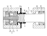
- FIG. 1 is a cross-sectional view conceptually showing a main part of a switchgear according to Embodiment 1 of the present invention.
- An arc extinguishing chamber installed in a tank (not shown) filled with an insulating gas and its vicinity are shown. It is shown in the figure.
- a fixed contact 1 of a switchgear has a cylindrical and longitudinal finger shape provided at the center, a fixed arc contact 11 where an arc is generated at the time of opening, and an outer peripheral portion of the fixed arc contact 11.
- the fixed main contacts 12 are arranged concentrically so as to form a cylindrical shape with a gap therebetween.
- the fixed-side shield 13 for electric field relaxation is installed so as to surround the fixed main contact 12.
- the movable contact 2 is brought into and out of contact with the fixed contact 1 so as to advance and retreat in the left-right direction in the figure by a driving device (not shown).
- a plurality of tubular current collectors 21 are disposed around the movable contact 2 and are always in sliding contact with the outer peripheral surface 2a with respect to the movement of the movable contact 2 in the axial direction.
- the outer periphery of the current collector 21 is surrounded by a movable shield 22 for electric field relaxation.
- the tip of the movable contact 2 on the fixed contact 1 side constitutes a contact portion 2b formed in a cylindrical shape, and the contact portion 2b is fixed to the fixed arc contact 11 of the fixed contact 1 when the switchgear is closed. It enters between the main contacts 12 and is electrically connected with a predetermined contact pressure by the fixed main contacts 12.
- the arc extinguishing member 3 constituting the arc extinguishing chamber has an enclosure 31 that is in sliding contact with the outer peripheral surface 2a of the movable contact 2 partway along the moving range from the closed state to the open state, and the arc space portion S. Is hermetically enclosed and fixed to the stationary shield 13.
- a predetermined portion of the surrounding portion 31 of the arc extinguishing member 3 has a plurality of through holes 31a for deflecting the extending direction of the generated arc A by a pressure gradient (in this example, two at the upper and lower symmetrical positions in the figure). ) It is provided.
- the arc extinguishing member 3 may be formed in a cylindrical shape as shown in FIG. 1, but may be formed in a donut shape as shown in FIGS. If the donut shape as shown in FIG. 9 is used, the number of parts to be cut when manufacturing is minimized, so that the processing cost can be reduced.
- the number of through holes 31a and the installation position in the circumferential direction are not particularly limited, and the wall surface of the surrounding portion 31 from the center side of the arc space portion S generated when the arc A is generated at one or more locations. What is necessary is just to be able to extend the arc A in the direction of the wall surface of the surrounding portion 31 by the pressure gradient that decreases toward the side, and it is not necessary to arrange the through hole 31a on the line object.
- FIG. 11 shows an example in which the through holes 31a are provided symmetrically in the vertical and horizontal directions.
- the arc space portion S is configured to include a surrounding portion 31 of the arc extinguishing member 3 and a space inside the contact portion 2 b formed in a cylindrical shape of the movable contact 2.
- the diameter of the through hole 31a on the outer peripheral surface side of the surrounding portion 31 of the arc extinguishing member 3 may be made larger than the diameter on the inner peripheral surface side of the surrounding portion 31 of the arc extinguishing member 3 as shown in FIG.
- a cylindrical arc extinguishing member 4 is provided inside the fixed arc contact 11 so as to protrude from the opening end portion of the fixed arc contact 11 in the opening direction of the movable contact 2.
- the arc extinguishing member 4 may have the same surface position as the open end of the fixed arc contact 11, but preferably projects in the direction of opening the movable contact 2 as shown in FIG. The When the movable contact 2 is opened, an insulation distance that does not cause a flash between the projecting end portion of the arc extinguishing member 4 and the movable contact 2 or the movable side shield 22 must be ensured when the movable contact 2 is opened. Don't be.
- Examples of materials that can be preferably used as the arc-extinguishing member 3 and the arc-extinguishing member 4 include, for example, polytetrafluoroethylene, polyacetal, acrylate copolymer, aliphatic hydrocarbon resin, polyvinyl alcohol, polybutadiene, and polyvinyl acetate. , Polyvinyl acetal, isoprene resin, ethylene propylene rubber, ethylene vinyl acetate copolymer, polyamide resin, or any combination thereof.
- the arc extinguishing member 3 and the arc extinguishing member 4 may be made of the same material or different from each other. For example, in the case of a three-phase alternating current, the required number of switchgears shown in FIG. 1 are prepared according to the number of phases and the like, and are arranged in parallel at a predetermined interval.
- FIG. 2 is a cross-sectional view taken along the line II-II in FIG. 6 is a cross-sectional view showing the closed state of FIG. 1
- FIG. 7 is a cross-sectional view showing a state in the middle of opening when the arc A is generated
- FIG. 8 is a cross-sectional view showing the complete open state.
- FIG. 7 is a cross-sectional view when the arc A is generated when the fixed arc contact 11 and the movable contact 2 are separated.
- the through hole 31 a is closed by the movable contact 2, so that it is surrounded by the movable contact 2 and the arc extinguishing member 3.
- the pressure in the arc space S increases due to the heat of the arc A.
- the arc extinguishing gas is stably generated in a larger amount from the arc extinguishing member 3, the arc A is decomposed or cooled by the arc extinguishing gas, so that the interruption performance is improved.
- the arc extinguishing gas is generated from the arc extinguishing member 4 to generate a pressure gradient. A flow is formed and the arc extinguishing gas acts to be blown against the arc A. For this reason, the cooling effect to the arc A increases and the interruption
- the tip of the movable contact 2 enters the movable shield 22 as shown in FIG.
- the arc extinguishing member 3 is formed so as to be in sliding contact with the outer peripheral surface 2a of the movable contact 2 partway along the moving range from the closed state to the open state. Since the cylindrical portion 31 is provided, the cylindrical portion 31 is provided with a through hole 31a for deflecting the direction of the generated arc toward the inner peripheral surface of the cylindrical portion 31 by a pressure gradient.
- the extending direction of the arc A is controlled by the pressure gradient generated inside the cylindrical portion 31, and the arc can be reliably brought into contact with the arc extinguishing member 3. For this reason, arc-extinguishing gas is generated stably and the arc-extinguishing performance of the switchgear can be improved. Further, by improving the arc extinguishing performance, it is possible to reduce the size of the apparatus and reduce the environmental load.
- the time during which the arc is controlled depends on the pressure. That is, even if the current approaches the zero point, the arc continues to contact the arc extinguishing member, and stable arc extinguishing gas can be expected to be generated.
- the extension direction of the arc is controlled using electromagnetic force, since the time during which the arc is controlled is determined by the current, the electromagnetic force is weakened near the current zero point, so there is a possibility that the arc extinguishing member will not be touched. Therefore, stable arc extinguishing gas generation cannot be expected.
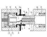
- FIG. 3 is a cross-sectional view conceptually showing a main part of the switchgear according to Embodiment 2 of the present invention
- FIG. 4 is a cross-sectional view taken along the line IV-IV in FIG.
- a through-hole 4 a is provided in the axial direction at the center of the arc extinguishing member 4.
- the through hole 4a communicates the arc extinguishing chamber formed by the arc extinguishing member 3 with a space in the tank filled with an insulating gas (not shown).
- Other configurations are the same as those in the first embodiment.
- the arc A when the arc A is generated, the arc A generates heat from the center side of the arc space portion S toward the through hole 4a in the center portion of the arc extinguishing member 4, and the surrounding portion.
- a pressure gradient that decreases in two directions of the through hole 31a direction of the 31 is generated, and a gas flow is formed in the direction of the broken line arrow D in FIG.
- a portion of the arc A existing on the fixed arc contact 11 side extends to the outer peripheral surface side of the arc extinguishing member 4 by receiving a gas flow, and contacts the arc extinguishing member 4.
- the portion of the arc A existing on the movable contact 2 side receives the gas flow and contacts the inner peripheral surface of the arc extinguishing member 3 as in the first embodiment. For this reason, since the arc A can be brought into contact with both the arc-extinguishing member 4 and the arc-extinguishing member 3 and the generation amount of the arc-extinguishing gas can be increased, the interruption performance is further improved.
- FIG. 5 is a sectional view conceptually showing a main part of the switchgear according to Embodiment 3 of the present invention.
- a permanent magnet 5 is provided in the center of the arc extinguishing member 4 so as to be embedded.
- the permanent magnet 5 is arranged in the direction of the north pole, the south pole, or the south pole, the north pole along the axial direction, that is, the driving direction of the movable contact 2.
- Other configurations are the same as those of the first embodiment.
- the permanent magnet 5 may be integrally embedded in the arc extinguishing member 4 or may be configured separately and incorporated into the arc extinguishing member 4 during assembly.
- the arc A rotates by receiving a force in the circumferential direction by the magnetic field generated by the permanent magnet 5. That is, since the arc A is driven in the rotation direction on the electrode, that is, the fixed arc contact 11, the interruption performance is improved by the temperature suppression of the electrode and the cooling effect of forced convection. At the same time, the arc A has a characteristic of extending along the longitudinal magnetic field of the permanent magnet 5, that is, the magnetic field in the opening direction of the movable contact 2, and the arc A is attracted to the permanent magnet 5.
- FIG. FIG. 13 is a sectional view conceptually showing a main part of a switchgear according to Embodiment 4 of the present invention.
- a through hole 4a is provided that penetrates the central portion of the arc extinguishing member 4 and the central portion of the permanent magnet 5 in the axial direction.
- the through hole 4a communicates the arc extinguishing chamber formed by the arc extinguishing member 3 with a space in the tank filled with an insulating gas (not shown).
- Other configurations are the same as those of the third embodiment.
- the arc A when the arc A is generated, the arc A generates heat from the center side of the arc space portion S toward the through hole 4a in the center portion of the arc extinguishing member 4, and the surrounding portion.
- a pressure gradient that decreases in two directions of the through hole 31a direction of the 31 is generated, and a gas flow is formed in the direction of the broken line arrow G in FIG.
- a portion of the arc A existing on the fixed arc contact 11 side extends to the outer peripheral surface side of the arc extinguishing member 4 by receiving a gas flow, and contacts the arc extinguishing member 4. Furthermore, the arc extinguishing member 4 is more reliably contacted by the characteristic of extending along the longitudinal magnetic field of the permanent magnet 5. On the other hand, the portion of the arc A existing on the movable contact 2 side receives the gas flow and contacts the inner peripheral surface of the arc extinguishing member 3 as in the first embodiment.
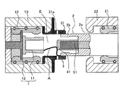
- FIG. FIG. 14 is a sectional view conceptually showing a main part of the switchgear according to Embodiment 5 of the present invention.
- an arc extinguishing member 41 is provided at the center of the movable contact 2.
- a through hole 41a penetrating in the axial direction is provided at the center of the arc extinguishing member 41, and an arc extinguishing chamber formed by the arc extinguishing member 3 and a tank filled with an insulating gas (not shown). It communicates with space.
- Other configurations are the same as those of the second embodiment.
- the portion of the arc A existing on the fixed arc contact 11 side is in contact with the outer peripheral surface of the arc extinguishing member 41 and the inner peripheral surface of the arc extinguishing member 3 by receiving the gas flow. For this reason, since the arc A can be brought into contact with both the arc extinguishing member 41 and the arc extinguishing member 3 and the amount of arc extinguishing gas generated can be increased in the same manner as in the second embodiment, it is further cut off. Performance is improved.
- FIG. 15 is a sectional view conceptually showing a main part of a switchgear according to Embodiment 6 of the present invention.
- an arc extinguishing member 41 is provided at the center of the movable contact 2.
- a permanent magnet 51 is provided in the center of the arc extinguishing member 41 so as to be embedded.
- the permanent magnet 51 is arranged in the direction of the north pole, the south pole, or the south pole, the north pole along the axial direction, that is, the driving direction of the movable contact 2.
- Other configurations are the same as those of the third embodiment.
- the permanent magnet 51 may be integrally embedded in the arc-extinguishing member 41, or may be configured separately and incorporated into the arc-extinguishing member 41 during assembly.
- the arc A rotates by receiving a force in the circumferential direction by the magnetic field generated by the permanent magnet 51. That is, since the arc A is driven in the rotational direction on the electrode, that is, the movable contact 2, the interruption performance is improved by the temperature suppression of the electrode and the cooling effect of forced convection. At the same time, the arc A has a characteristic of extending along the longitudinal magnetic field of the permanent magnet 51, that is, the magnetic field in the opening direction of the movable contact 2, and the arc A is attracted to the permanent magnet 51.
- the arc A attracted by the permanent magnet 51 comes into stable contact with the arc extinguishing member 41. For this reason, since the arc A can be brought into contact with both the arc extinguishing member 41 and the arc extinguishing member 3 and the amount of arc extinguishing gas generated can be increased in the same manner as in the third embodiment, it is further cut off. Performance can be improved.
- FIG. FIG. 16 is a sectional view conceptually showing a main part of the switchgear according to Embodiment 7 of the present invention.
- the fixed contact 1 is composed only of the fixed main contact 12.
- Other configurations are the same as those in the first embodiment.
- an arc A is generated between the fixed main contact 12 and the movable contact 2. Then, due to the heat of the arc A, a pressure gradient that decreases in the two directions in the direction of the through hole 31a of the surrounding portion 31 from the center side of the arc space portion S is generated, and a gas flow is formed in the direction of the broken line arrow I in FIG.
- the arc A receives the gas flow and contacts the inner peripheral surface of the arc extinguishing member 3 as in the first embodiment. For this reason, the arc A can be reliably brought into contact with the arc extinguishing member 3, and the amount of arc extinguishing gas generated can be increased as in the first embodiment, so that the interruption performance is further improved.
- FIG. 17 is a sectional view conceptually showing a main part of the switchgear according to Embodiment 8 of the present invention.
- the fixed contact 1 is composed only of the fixed main contact 12.
- an arc extinguishing member 41 is provided at the center of the movable contact 2.
- a permanent magnet 51 is provided in the center of the arc extinguishing member 41 so as to be embedded.
- the permanent magnet 51 is arranged in the direction of the north pole, the south pole, or the south pole and the north pole along the axial direction, that is, the driving direction of the movable contact 2.
- Other configurations are the same as those of the seventh embodiment.
- the permanent magnet 51 may be integrally embedded in the arc-extinguishing member 41, or may be configured separately and incorporated into the arc-extinguishing member 41 during assembly.
- an arc A is generated between the fixed main contact 12 and the movable contact 2.
- the arc A rotates by receiving a force in the circumferential direction by a magnetic field generated by the permanent magnet 51. That is, since the arc A is driven in the rotational direction on the electrode, that is, the movable contact 2, the interruption performance is improved by the temperature suppression of the electrode and the cooling effect of forced convection.
- the arc A has a characteristic of extending along the longitudinal magnetic field of the permanent magnet 51, that is, the magnetic field in the opening direction of the movable contact 2, and the arc A is attracted to the permanent magnet 51. Since the periphery of the permanent magnet 51 is covered and protected by the arc extinguishing member 41, the arc A drawn by the permanent magnet 51 comes into stable contact with the arc extinguishing member 41. For this reason, since the arc A can be brought into contact with both the arc extinguishing member 41 and the arc extinguishing member 3 and the amount of arc extinguishing gas generated can be increased in the same manner as in the third embodiment, it is further cut off. Performance can be improved.
- the arc extinguishing member 41 and the permanent magnet 51 can be enlarged. For this reason, the contact probability of the arc extinguishing member 41 can be increased, the magnetic flux density of the permanent magnet 51 can be further increased, and the amount of arc extinguishing gas generated can be increased. Can be improved.
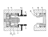
- FIG. FIG. 18 is a sectional view conceptually showing a main part of a switchgear according to Embodiment 9 of the present invention.
- the arc-extinguishing member 30 has an enclosure 310 that slidably contacts the outer peripheral surface 2a of the movable contact 2 partway along the moving range from the closed state to the open state, and the arc space S is sealed. And is fixed to the movable shield 22.
- An encircling portion 310 that is in sliding contact with the outer peripheral surface of the movable contact 2 is formed so as to extend in the direction of the fixed contact 1.
- Other configurations are the same as those in the first embodiment.
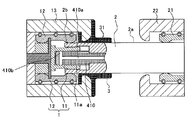
- FIG. FIG. 19 is a cross-sectional view in a closed state conceptually showing the main part of the switchgear according to Embodiment 10 of the present invention.
- an arc extinguishing member 410 is provided at the center of the movable contact 2, and the outer peripheral surface of the arc extinguishing member 410 is formed so as to be in sliding contact with the inner peripheral surface 11 a of the fixed arc contact 11. Yes.
- a central hole 410a formed in the axial direction is provided at the center of the arc extinguishing member 410, and a radial through hole 410b communicating with the central hole 410a is provided at an end of the arc extinguishing member 410 on the stationary contact side.
- the arc-extinguishing chamber formed by the arc-extinguishing member 3 communicates with a space in the tank filled with an insulating gas (not shown).
- the arc extinguishing member 3 constituting the arc extinguishing chamber has an enclosure portion 31 that slidably contacts the outer peripheral surface 2a of the movable contact 2 partway along the moving range from the closed state to the open state. It is formed so as to enclose the part S in a sealed manner, and is fixed to the fixed shield 13 side.
- the through hole 31a was present in a predetermined portion of the surrounding part 31 of the arc extinguishing member 3, but in the tenth embodiment, the through hole 31a is not present.
- Other configurations are the same as those of the first embodiment.
- FIG. 20 is a cross-sectional view showing a state in the middle of opening when the arc A is generated
- FIG. 21 is a cross-sectional view showing a state in the middle of opening when the through hole 410b is opened.
- the switchgear when the switchgear is in a closed state as shown in FIG. 19, the current is passed through the fixed main contact 12, the movable contact 2 and the current collector 21. is doing.
- the movable contact 2 is driven rightward in FIG. 19 by a driving device (not shown).
- a driving device not shown
- the fixed main contact 12 and the movable contact 2 are separated, and the current flowing through the fixed main contact 12 is commutated to the fixed arc contact 11.
- the fixed arc contact 11 and the movable contact 2 are separated with a time delay, and an arc A is generated.
- FIG. 20 is a sectional view when the arc A is generated when the fixed arc contact 11 and the movable contact 2 are separated.
- the through hole 410 b is closed by the fixed arc contact 11, so that it is surrounded by the movable contact 2 and the arc extinguishing member 3.
- the pressure in the arc space S increases due to the heat of the arc A.
- the arc A is decomposed or cooled by the arc extinguishing gas, so that the interruption performance is improved. Further, when the arc A comes into contact with the arc extinguishing member 410 provided at the center of the fixed arc contact 11, the arc extinguishing gas is also generated from the arc extinguishing member 410, thereby generating a pressure gradient. A flow is formed and the arc extinguishing gas acts to be blown against the arc A. For this reason, the cooling effect to the arc A increases and the interruption
- the number of through-holes 410b and the installation position in the circumferential direction are not particularly limited, and the number of through-holes 410b is one or more, and is directed from the center side of the arc space S generated along with the generation of the arc A to the through-hole 410b. It is only necessary that the arc A can be extended to the outer peripheral surface of the arc extinguishing member 410 due to the decreasing pressure gradient, and it is not necessary to arrange the through hole 410b on the line object.
- the arc space and the outside of the arc space are communicated with each other by the through-hole provided in the surrounding portion of the arc extinguishing member, so that the arc extending direction is reliably brought into contact with the arc extinguishing member. It is suitable for realizing a highly reliable switchgear that can be used.
Landscapes
- Arc-Extinguishing Devices That Are Switches (AREA)
- Circuit Breakers (AREA)
Abstract
Priority Applications (4)
| Application Number | Priority Date | Filing Date | Title |
|---|---|---|---|
| US13/824,586 US9117608B2 (en) | 2011-01-07 | 2011-08-26 | Switchgear |
| EP11854626.6A EP2662877B1 (fr) | 2011-01-07 | 2011-08-26 | Appareil de commutation |
| JP2012551790A JP5389279B2 (ja) | 2011-01-07 | 2011-08-26 | 開閉装置 |
| CN201180053688.4A CN103201809B (zh) | 2011-01-07 | 2011-08-26 | 开闭装置 |
Applications Claiming Priority (2)
| Application Number | Priority Date | Filing Date | Title |
|---|---|---|---|
| JP2011001572 | 2011-01-07 | ||
| JP2011-001572 | 2011-01-07 |
Publications (1)
| Publication Number | Publication Date |
|---|---|
| WO2012093507A1 true WO2012093507A1 (fr) | 2012-07-12 |
Family
ID=46457371
Family Applications (1)
| Application Number | Title | Priority Date | Filing Date |
|---|---|---|---|
| PCT/JP2011/069283 WO2012093507A1 (fr) | 2011-01-07 | 2011-08-26 | Appareil de commutation |
Country Status (5)
| Country | Link |
|---|---|
| US (1) | US9117608B2 (fr) |
| EP (1) | EP2662877B1 (fr) |
| JP (1) | JP5389279B2 (fr) |
| CN (1) | CN103201809B (fr) |
| WO (1) | WO2012093507A1 (fr) |
Cited By (6)
| Publication number | Priority date | Publication date | Assignee | Title |
|---|---|---|---|---|
| CN103971981A (zh) * | 2013-01-28 | 2014-08-06 | 株式会社日立制作所 | 气体绝缘开关装置 |
| JP2015220094A (ja) * | 2014-05-19 | 2015-12-07 | 三菱電機株式会社 | 開閉装置 |
| WO2018109931A1 (fr) * | 2016-12-16 | 2018-06-21 | 株式会社 東芝 | Dispositif de commutation à isolation gazeuse |
| JP2020042985A (ja) * | 2018-09-11 | 2020-03-19 | 日新電機株式会社 | ガス遮断器 |
| JP6837607B1 (ja) * | 2020-01-27 | 2021-03-03 | 三菱電機株式会社 | ガス絶縁開閉装置 |
| JP2021077542A (ja) * | 2019-11-11 | 2021-05-20 | 三菱電機株式会社 | ガス絶縁開閉装置 |
Families Citing this family (15)
| Publication number | Priority date | Publication date | Assignee | Title |
|---|---|---|---|---|
| EP2629313A1 (fr) * | 2012-02-17 | 2013-08-21 | ABB Technology AG | Disjoncteur à isolation gazeuse doté d'un agencement de blindage par contact nominal |
| JP2014235954A (ja) * | 2013-06-05 | 2014-12-15 | 株式会社日立製作所 | ガス絶縁開閉器 |
| CN104143467B (zh) * | 2013-09-30 | 2017-07-21 | 国家电网公司 | 一种压气式灭弧装置及使用该灭弧装置的高压断路器 |
| DE102013223632A1 (de) * | 2013-11-20 | 2015-05-21 | Siemens Aktiengesellschaft | Schaltanordnung sowie Verfahren zur Montage einer Schaltanordnung |
| CN103794386A (zh) * | 2014-01-15 | 2014-05-14 | 北京华东电气股份有限公司 | Sf6组合电器的夹板式梅花触头 |
| US9343252B2 (en) * | 2014-08-27 | 2016-05-17 | Eaton Corporation | Arc extinguishing contact assembly for a circuit breaker assembly |
| FR3028089B1 (fr) * | 2014-10-30 | 2016-12-30 | Alstom Technology Ltd | Interrupteur ou disjoncteur a moyenne ou haute tension, pourvu de contacts fixes ameliores, et procede d'utilisation |
| US10033169B2 (en) * | 2015-05-26 | 2018-07-24 | Mitsubishi Electric Corporation | Electric device and method for manufacturing electric device |
| US10256058B2 (en) * | 2015-11-16 | 2019-04-09 | Mitsubishi Electric Corporation | Switchgear |
| EP3441998B1 (fr) * | 2016-04-06 | 2019-10-09 | Mitsubishi Electric Corporation | Interrupteur |
| US10395855B2 (en) * | 2016-04-28 | 2019-08-27 | Mitsubishi Electric Corporation | Switch |
| US11227735B2 (en) * | 2017-12-01 | 2022-01-18 | Kabushiki Kaishatoshiba | Gas circuit breaker |
| JP7155283B2 (ja) * | 2018-10-26 | 2022-10-18 | 株式会社東芝 | ガス遮断器 |
| WO2021138366A1 (fr) * | 2019-12-31 | 2021-07-08 | Southern States Llc | Commutateur de puissance électrique haute tension avec électrodes d'arc de carbone et gaz diélectrique de dioxyde de carbone |
| CN111161965B (zh) * | 2019-12-31 | 2022-05-17 | 平高集团有限公司 | 一种静触头及高压开关 |
Citations (4)
| Publication number | Priority date | Publication date | Assignee | Title |
|---|---|---|---|---|
| JPS5347970A (en) * | 1976-10-13 | 1978-04-28 | Mitsubishi Electric Corp | Electric switch |
| JPH0883545A (ja) * | 1994-09-12 | 1996-03-26 | Fuji Electric Co Ltd | ガス開閉器 |
| JPH10208593A (ja) * | 1997-01-22 | 1998-08-07 | Fuji Electric Co Ltd | ガス開閉器 |
| JP2002334636A (ja) * | 2001-05-09 | 2002-11-22 | Mitsubishi Electric Corp | ガス絶縁断路器 |
Family Cites Families (22)
| Publication number | Priority date | Publication date | Assignee | Title |
|---|---|---|---|---|
| FR1500340A (fr) * | 1966-09-22 | 1967-11-03 | Tuyère de coupure pour interrupteur à gaz comprimé | |
| IT985690B (it) * | 1973-06-14 | 1974-12-10 | Magrini Fab Riun Scarpa | Camera di interruzione per interrut tori elettrici a gas compresso auto soffiante |
| JPS5919293Y2 (ja) * | 1979-07-02 | 1984-06-04 | 日新電機株式会社 | ア−ク回転形しや断器 |
| DE3474081D1 (en) * | 1983-05-09 | 1988-10-20 | Mitsubishi Electric Corp | Circuit breaker of spiral arc type |
| AU638851B2 (en) * | 1990-07-27 | 1993-07-08 | Hitachi Limited | Puffer type gas-insulated circuit breaker |
| JPH069029A (ja) | 1992-06-26 | 1994-01-18 | Daifuku Co Ltd | 接続可能なコンベヤ装置 |
| JPH069029U (ja) * | 1992-07-07 | 1994-02-04 | 株式会社明電舎 | ガス断路器 |
| JPH0652761A (ja) * | 1992-08-01 | 1994-02-25 | Mitsubishi Electric Corp | 開閉器 |
| FR2711269B1 (fr) * | 1993-10-12 | 1995-12-29 | Gec Alsthom T & D Sa | Disjoncteur à haute tension capable de couper des courants de défaut à passage par zéro retardé. |
| JPH08212885A (ja) * | 1995-02-03 | 1996-08-20 | Hitachi Ltd | パッファ形ガス遮断器 |
| DE19517615A1 (de) * | 1995-05-13 | 1996-11-14 | Abb Research Ltd | Leistungsschalter |
| DE19533794A1 (de) * | 1995-09-13 | 1997-03-20 | Abb Patent Gmbh | Metallgekapselter, gasisolierter Hochspannungsschalter |
| FR2808118B1 (fr) * | 2000-04-19 | 2004-06-18 | Alstom | Interrupteur a auto-soufflage avec une chambre de coupure a deux volumes |
| JP4218216B2 (ja) * | 2001-02-22 | 2009-02-04 | 株式会社日立製作所 | ガス遮断器 |
| FR2821482B1 (fr) * | 2001-02-27 | 2003-04-04 | Alstom | Disjoncteur incluant un canal de vidange de la chambre de compression par piston |
| EP1276125A3 (fr) * | 2001-06-27 | 2004-05-06 | Siemens Aktiengesellschaft | Disjoncteur |
| JP4197406B2 (ja) * | 2002-05-23 | 2008-12-17 | 三菱電機株式会社 | ガス絶縁開閉器 |
| EP1826792B1 (fr) * | 2006-02-28 | 2008-09-03 | ABB Research Ltd | Chambre de coupure d'un disjoncteur haute tension avec un volume de chauffage recevant le gaz de soufflage généré par l'arc |
| JP2008218001A (ja) | 2007-02-28 | 2008-09-18 | Mitsubishi Electric Corp | ガス開閉器の電極装置 |
| US8742282B2 (en) * | 2007-04-16 | 2014-06-03 | General Electric Company | Ablative plasma gun |
| DE102008039813A1 (de) * | 2008-08-25 | 2010-03-04 | Siemens Aktiengesellschaft | Hochspannungs-Leistungsschalter mit einer Schaltstrecke |
| WO2010150390A1 (fr) * | 2009-06-25 | 2010-12-29 | 三菱電機株式会社 | Mécanisme de commutation à isolation au gaz |
-
2011
- 2011-08-26 EP EP11854626.6A patent/EP2662877B1/fr active Active
- 2011-08-26 WO PCT/JP2011/069283 patent/WO2012093507A1/fr active Application Filing
- 2011-08-26 CN CN201180053688.4A patent/CN103201809B/zh not_active Expired - Fee Related
- 2011-08-26 JP JP2012551790A patent/JP5389279B2/ja not_active Expired - Fee Related
- 2011-08-26 US US13/824,586 patent/US9117608B2/en active Active
Patent Citations (4)
| Publication number | Priority date | Publication date | Assignee | Title |
|---|---|---|---|---|
| JPS5347970A (en) * | 1976-10-13 | 1978-04-28 | Mitsubishi Electric Corp | Electric switch |
| JPH0883545A (ja) * | 1994-09-12 | 1996-03-26 | Fuji Electric Co Ltd | ガス開閉器 |
| JPH10208593A (ja) * | 1997-01-22 | 1998-08-07 | Fuji Electric Co Ltd | ガス開閉器 |
| JP2002334636A (ja) * | 2001-05-09 | 2002-11-22 | Mitsubishi Electric Corp | ガス絶縁断路器 |
Non-Patent Citations (1)
| Title |
|---|
| See also references of EP2662877A4 * |
Cited By (9)
| Publication number | Priority date | Publication date | Assignee | Title |
|---|---|---|---|---|
| CN103971981A (zh) * | 2013-01-28 | 2014-08-06 | 株式会社日立制作所 | 气体绝缘开关装置 |
| JP2015220094A (ja) * | 2014-05-19 | 2015-12-07 | 三菱電機株式会社 | 開閉装置 |
| WO2018109931A1 (fr) * | 2016-12-16 | 2018-06-21 | 株式会社 東芝 | Dispositif de commutation à isolation gazeuse |
| JPWO2018109931A1 (ja) * | 2016-12-16 | 2019-10-24 | 東芝エネルギーシステムズ株式会社 | ガス絶縁開閉装置 |
| JP2020042985A (ja) * | 2018-09-11 | 2020-03-19 | 日新電機株式会社 | ガス遮断器 |
| JP2021077542A (ja) * | 2019-11-11 | 2021-05-20 | 三菱電機株式会社 | ガス絶縁開閉装置 |
| JP7172960B2 (ja) | 2019-11-11 | 2022-11-16 | 三菱電機株式会社 | ガス絶縁開閉装置 |
| JP6837607B1 (ja) * | 2020-01-27 | 2021-03-03 | 三菱電機株式会社 | ガス絶縁開閉装置 |
| WO2021152646A1 (fr) * | 2020-01-27 | 2021-08-05 | 三菱電機株式会社 | Appareillage de commutation isolé au gaz |
Also Published As
| Publication number | Publication date |
|---|---|
| JPWO2012093507A1 (ja) | 2014-06-09 |
| US20130270228A1 (en) | 2013-10-17 |
| EP2662877A4 (fr) | 2014-12-17 |
| CN103201809A (zh) | 2013-07-10 |
| CN103201809B (zh) | 2016-05-04 |
| US9117608B2 (en) | 2015-08-25 |
| JP5389279B2 (ja) | 2014-01-15 |
| EP2662877B1 (fr) | 2019-09-25 |
| EP2662877A1 (fr) | 2013-11-13 |
Similar Documents
| Publication | Publication Date | Title |
|---|---|---|
| JP5389279B2 (ja) | 開閉装置 | |
| KR102156992B1 (ko) | 릴레이 | |
| KR101704807B1 (ko) | 차단기용 전자반발 조작기 | |
| JP4612495B2 (ja) | ガス絶縁開閉器 | |
| WO2015029606A1 (fr) | Commutateur | |
| JP6053173B2 (ja) | 開閉装置 | |
| KR101604368B1 (ko) | 가스 절연 개폐기 | |
| JP6029524B2 (ja) | 開閉装置 | |
| JP3431439B2 (ja) | 絶縁開閉装置 | |
| US20190252139A1 (en) | Electrical interruption device | |
| JP6837607B1 (ja) | ガス絶縁開閉装置 | |
| JP2002334636A (ja) | ガス絶縁断路器 | |
| KR100988116B1 (ko) | 진공 인터럽터 및 이를 구비하는 진공 차단기 | |
| JP6958882B2 (ja) | 瞬間的な高電流の影響に対して耐性を有する高電圧リレー | |
| KR101121913B1 (ko) | 가스 절연 개폐장치용 통전부의 패킹 어셈블리 | |
| KR101935376B1 (ko) | 고전압 개폐기 | |
| JP2010061858A (ja) | ガス遮断器 | |
| JP5512474B2 (ja) | 開閉装置 | |
| US20230141161A1 (en) | Vacuum interrupter anti-bounce dampener | |
| AU2022388491A1 (en) | Vacuum interrupter anti-bounce dampener | |
| JPH07111852B2 (ja) | 開閉器 | |
| KR101621765B1 (ko) | 개폐장치 | |
| JP2015220094A (ja) | 開閉装置 | |
| JP2012243574A (ja) | 開閉器 | |
| CN110739175A (zh) | 提高直动式高压开关小电流开断能力的装置 |
Legal Events
| Date | Code | Title | Description |
|---|---|---|---|
| WWE | Wipo information: entry into national phase |
Ref document number: 201180053688.4 Country of ref document: CN |
|
| 121 | Ep: the epo has been informed by wipo that ep was designated in this application |
Ref document number: 11854626 Country of ref document: EP Kind code of ref document: A1 |
|
| WWE | Wipo information: entry into national phase |
Ref document number: 2012551790 Country of ref document: JP |
|
| WWE | Wipo information: entry into national phase |
Ref document number: 13824586 Country of ref document: US |
|
| WWE | Wipo information: entry into national phase |
Ref document number: 2011854626 Country of ref document: EP |
|
| NENP | Non-entry into the national phase |
Ref country code: DE |