WO2012091497A2 - 양팔 혈압의 동시 자동측정을 통한 양팔혈압 측정장치 - Google Patents
양팔 혈압의 동시 자동측정을 통한 양팔혈압 측정장치 Download PDFInfo
- Publication number
- WO2012091497A2 WO2012091497A2 PCT/KR2011/010323 KR2011010323W WO2012091497A2 WO 2012091497 A2 WO2012091497 A2 WO 2012091497A2 KR 2011010323 W KR2011010323 W KR 2011010323W WO 2012091497 A2 WO2012091497 A2 WO 2012091497A2
- Authority
- WO
- WIPO (PCT)
- Prior art keywords
- blood pressure
- arm
- arms
- bladder
- measurement
- Prior art date
- Legal status (The legal status is an assumption and is not a legal conclusion. Google has not performed a legal analysis and makes no representation as to the accuracy of the status listed.)
- Ceased
Links
Images


Classifications
-
- A—HUMAN NECESSITIES
- A61—MEDICAL OR VETERINARY SCIENCE; HYGIENE
- A61B—DIAGNOSIS; SURGERY; IDENTIFICATION
- A61B5/00—Measuring for diagnostic purposes; Identification of persons
- A61B5/02—Detecting, measuring or recording for evaluating the cardiovascular system, e.g. pulse, heart rate, blood pressure or blood flow
- A61B5/021—Measuring pressure in heart or blood vessels
- A61B5/022—Measuring pressure in heart or blood vessels by applying pressure to close blood vessels, e.g. against the skin; Ophthalmodynamometers
- A61B5/02233—Occluders specially adapted therefor
-
- A—HUMAN NECESSITIES
- A61—MEDICAL OR VETERINARY SCIENCE; HYGIENE
- A61B—DIAGNOSIS; SURGERY; IDENTIFICATION
- A61B5/00—Measuring for diagnostic purposes; Identification of persons
- A61B5/02—Detecting, measuring or recording for evaluating the cardiovascular system, e.g. pulse, heart rate, blood pressure or blood flow
- A61B5/021—Measuring pressure in heart or blood vessels
- A61B5/022—Measuring pressure in heart or blood vessels by applying pressure to close blood vessels, e.g. against the skin; Ophthalmodynamometers
- A61B5/0225—Measuring pressure in heart or blood vessels by applying pressure to close blood vessels, e.g. against the skin; Ophthalmodynamometers the pressure being controlled by electric signals, e.g. derived from Korotkoff sounds
-
- A—HUMAN NECESSITIES
- A61—MEDICAL OR VETERINARY SCIENCE; HYGIENE
- A61B—DIAGNOSIS; SURGERY; IDENTIFICATION
- A61B5/00—Measuring for diagnostic purposes; Identification of persons
- A61B5/02—Detecting, measuring or recording for evaluating the cardiovascular system, e.g. pulse, heart rate, blood pressure or blood flow
- A61B5/024—Measuring pulse rate or heart rate
-
- A—HUMAN NECESSITIES
- A61—MEDICAL OR VETERINARY SCIENCE; HYGIENE
- A61B—DIAGNOSIS; SURGERY; IDENTIFICATION
- A61B5/00—Measuring for diagnostic purposes; Identification of persons
- A61B5/74—Details of notification to user or communication with user or patient; User input means
- A61B5/742—Details of notification to user or communication with user or patient; User input means using visual displays
Definitions
- the present invention relates to an apparatus for measuring both arms blood pressure through simultaneous automatic measurement of both arms blood pressure.
- the present invention relates to a double-arm blood pressure measuring apparatus through simultaneous automatic measurement of both-arm blood pressure to measure the blood pressure difference in the two arms of the human body to measure the state related to blood flow or blood pressure.
- Hypertension which is a problem in modern society, is one of the important conditions for proper treatment.
- the World Health Organization defines that the difference in bilateral blood pressure is a risk factor for diseases of the circulatory system when the maximum blood pressure is 20 mmHg or the minimum blood pressure is 10 mmHg or more.
- Japanese Patent Laid-Open No. 11-342117 discloses a device having a left blood pressure measuring device for measuring the blood pressure of the left arm and a right blood pressure measuring device for measuring the blood pressure of the right arm.
- the device starts to measure the blood pressure of the left arm by pressing the microswitch installed on the left arm support.
- the microswitch installed on the right arm support is pressed to the right arm.
- Japanese Patent Laid-Open No. 2010-119639 automatically recognizes that when the left arm is inserted into the cuff unit, it measures the blood pressure of the left arm, and when the right arm is inserted into the cuff unit, it automatically measures the blood pressure of the right arm.
- a device for recognizing is disclosed. However, it is impossible for the subject to measure the blood pressure of the left and right arms simultaneously under the same conditions with one start button.
- Japanese Patent Laid-Open No. 2009-523512 discloses an apparatus for winding two cuffs on the left and right arms of a subject and measuring both blood pressures.
- the position where the cuff is wound may be different, and the strength at the right and left sides of the cuff is different, so it is difficult to measure the same pressure.
- the present invention was developed in view of the above problems of the blood pressure device, and the left and right cuff units have the same structure so as to be measured at the same pressure at the same position at the same time when measuring the blood pressure of the left and right arms. That is, the size and structure of the cells of the left and right cuff units are the same, and the sizes of the internal spaces are the same, and portions corresponding to each other in the cells of the left and right cuff units have the same height. In addition, the size and volume of the bladder located inside the cells of the left and right cuff units are the same.
- the present invention allows the subject to measure the blood pressure at the same position at the same height and at the same position at the same position on the measurement site of the left and right arms.
- the blood pressure measurement values of the left and right arms of the subject can be displayed on the result screen at the same time as the end of the measurement.
- the same condition means that the height of the measurement site is the same in both arms, and the pressure applied to the measurement site is the same.
- Simultaneous means that both blood pressure measurements are performed at the same time in time using one start button.
- An object of the present invention is to provide an automatic blood pressure measuring device and a blood pressure difference display device capable of simultaneously measuring blood pressure under the same conditions of both arms of the subject.
- Another object of the present invention is an automatic blood pressure measuring device and a blood pressure difference that can measure blood pressure safely at the same time without removing the arm under the same posture condition after the subject puts both arms in the cuff under the same conditions. It is to provide a display device.
- Still another object of the present invention is to provide a biceps blood pressure measuring device that can be easily and simply operated by the elderly.
- Still another object of the present invention is to provide an automatic blood pressure measuring device and a blood pressure difference display device which can measure blood pressure of both arms at the same time, and can easily measure the blood pressure by arbitrarily selecting the left and right arms. .
- Both arms blood pressure measuring apparatus of the present invention for achieving the above object includes a left cuff unit and a right cuff unit, including the bladder that can put the arm of the subject and automatically wound on the arm, the left cuff unit and the right A CPU for controlling the cuff unit;
- the left and right cuff units are symmetrical in structure so that the blood pressure measurement sites of the left and right arms of the subject located in the inner space of the cuff unit are equal, respectively.
- the shape of the front opening and the rear opening and the size of the inner space are the same, and the volume of the bladder of each cuff unit is the same so that the blood pressure measurement of the blood pressure measurement sites of the left and right arms of the subject to be positioned is performed under the same conditions. I will,
- the CPU is achieved by a configuration in which the blood pressure is measured at the same time by driving the left and right cuff units simultaneously when the left and right arms of the subject are located in the inner spaces of the left and right units.
- the device is a bladder of the left cuff unit and the bladder of the right cuff unit wraps the blood pressure measurement site in the same position of the left and right arms of the subject.
- the bladder of the left cuff unit and the bladder of the right cuff unit are symmetrical to surround the arterial vessels of both arms.
- the device of the present invention has a symmetrical structure so that the blood pressure measurement sites of the left and right arms are the same in automatically and simultaneously measuring blood pressure of both arms, and is located in the inner space of the left and right cuff units.
- the shape of the front opening and the rear opening and the size of the inner space are the same, and the volume of the bladder of each cuff unit is the same so that the blood pressure measurement of the blood pressure measurement sites of the left and right arms is performed under the same conditions.
- control unit When the left arm and the right arm of the subject are located in the inner space of the left and right cuff units, the control unit simultaneously drives the left and right cuff units so that blood pressure is measured at the same time. The difference between the blood pressure and the bilateral blood pressure is indicated.
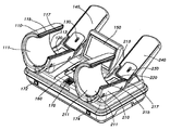
- FIG. 1 is a perspective view showing a bi-arm blood pressure measuring apparatus of the present invention.
- Figure 2 is a plan view showing a two-arm blood pressure measuring apparatus of the present invention.
- FIG. 3 is a cutaway view of a portion of the left and right cuff units in FIG. 1.
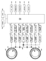
- Figure 4 is a block diagram showing the circuit configuration of the bi-arm blood pressure measuring apparatus of the present invention.
- FIG. 5 is a flowchart for explaining the operation of the blood pressure measuring device for both arms of the present invention.
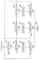
- FIG. 6 is a subroutine for explaining an operation of measuring blood pressure of the left and right arms of FIG. 5.
- FIG. 7 is a subroutine for explaining an operation of measuring blood pressure of the left arm in FIG. 5.
- FIG. 8 is a subroutine for explaining an operation of measuring blood pressure of the right arm in FIG. 5.
- FIG. 9 is a flowchart for explaining the operation of the emergency switch in the two-arm blood pressure measuring apparatus of the present invention.
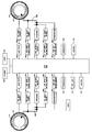
- Figure 10 is another embodiment of the bilateral arm blood pressure measuring apparatus of the present invention.
- FIG. 12 is a view showing a state in which the measurement results of the blood pressure of the left and right arms are displayed on the screen as the highest blood pressure, the lowest blood pressure, and the difference.
- FIG. 1 is a perspective view showing a bi-arm blood pressure measuring apparatus of the present invention.
- Figure 2 is a plan view showing a two-arm blood pressure measuring apparatus of the present invention.
- FIG. 3 is a cutaway view of a portion of the left and right cuff units in FIG. 1.
- the automatic arm measuring blood pressure monitor includes a main body 100 mounted on a mounting table such as a desk, a left cuff unit 110 positioned on an upper left side of the main body 100, and The right cuff unit 210 is located on the upper right side of the main body 100.
- the left and right cuff units 110 and 210 respectively include substantially cylindrical cells 115 and 215 and bladders 117 and 217 housed inside the cells 115 and 215.
- Each of the cells 115 and 215 has a space portion extending from the front openings 111 and 211 so that the left forearm and the right forearm of the subject pass, and the rear of the space portion is the left forearm and the right forearm passing through the space.
- the rear openings 113 and 213 are provided so that they can escape.
- Each bladder 117, 217 is wrapped in a fabric and received at the inner periphery of the corresponding respective cell 115, 215, with one side of each cell 115, 215 being a respective cell 115, 215. It is a surface surrounding the left arm and the right arm of the subject located in the space portion of () (see Fig. 3).
- the left and right cuff units 110 and 210 have the same structure in their size and shape so that the blood pressures of the left and right arms of the subject are measured under the same conditions.
- each of the bladders 117 and 217 housed in the inner periphery of each of the cells 115 and 215 has the same shape and volume, so that the same amount of air is injected into each of the bladders 117 and 217.
- the left forearm and the right forearm of the subject passing through each of the cells 115 and 215 are wrapped with the same pressure.
- the left bladder 117 and the right bladder 217 face to each other so that the bladder can measure the same area of the artery passing through the left and right arms which are symmetric to each other. It is coming true. This is because the arteries passing the left and right arms are symmetric with each other.
- the bladders 117 and 217 can wrap the arteries of the left and right arms of the subject under the same pressure.
- the display apparatus 150 is installed on the upper surface of the main body 100 between the left and right cuff units 110 and 210, and the printer 160 is installed in front of the main body 100.
- the start switch 170 is exposed in front of the upper surface of the main body 100.
- the start switch can be connected to the main body as a switch that can be held by the subject or can be pressed by foot.
- Emergency switches 172 and 174 are exposed on both the front left and right sides of the main body. As shown in Figure 11 below, the emergency switch can be used by connecting to the main body as a switch that can be held by the subject or can be pressed by foot.
- elbow supports 120 and 220 are provided for placing the elbows of the subject passing through the internal spaces of the cuff units 110 and 210. have. From each of the elbow rests 120 and 220, arm supports 140 and 240 supporting the lower arms and the cuffs of the left and right sides of the subject, respectively, are erected upwardly. In addition, under each of the arm supports 140 and 240, arm detection sensors 130 and 230 are mounted to detect the arm of the subject.
- Arm detection sensors 130 and 230 positioned below the respective arm supports 140 and 240 detect the arm of the subject placed on the arm supports 140 and 240 and transmit the signal to the CPU.
- the subject inserts the lower arm and the wrist into the openings 111 and 211 of the left and right cuff units 110 and 210 so as to pass through the inner space, the elbow is placed on the elbow supports 120 and 220, and the lower arm When the cuffs and the cuffs are placed obliquely along the arm supports 140 and 240, the measuring portions of the upper arm on the left and right sides of the subject are positioned at the same height in the left and right cuff units, respectively.
- the left and right bladders 117 and 217 cover the measurement portions of the left and right upper arms at the same pressure.
- an electronic circuit device including an air pump, a measuring circuit, and a CPU for supplying compressed air to the bladder on the left and right sides is embedded. Under the control of the CPU, the measurement results of the left cuff unit and the right cuff unit are displayed on the display device 150, and the measurement results can be output to the printer 160.
- Figure 4 is a block diagram showing the configuration of the blood pressure measuring device for both arms of the present invention.
- an air supply pipe 309 through which air is injected from the air pump 303 is connected to the left bladder 117 constituting the left cuff unit 110, and the left bladder 117 is connected to the left bladder 117.
- a left pressure sensor 341 for detecting pressure is attached.
- the left bladder pressure valve 333, the left bladder exhaust valve 353, and the quick exhaust valve 306 are attached to the air supply pipe 309 that supplies air from the air pump 303 to the left bladder 117. have.
- a rapid exhaust valve 306 is attached to the air supply pipe 309 that supplies air to the left and right bladders 117 and 217.
- An air supply pipe 309 through which air is injected from the air pump 303 is connected to the right bladder 217 constituting the right cuff unit 210, and the right pressure sensor detects the pressure of the right bladder 217. 441 is attached.
- a right bladder pressurizing valve 433 and a right bladder exhaust valve 453 are attached to the air supply pipe 309 that supplies air from the air pump 303 to the right bladder 217.
- the pressure of the left bladder 117 is detected by the left pressure sensor 341 and transmitted to the CPU 300 over the left A / D converter 343, and the pressure of the right bladder 217 is controlled by the right pressure sensor ( 441 is passed to the CPU 300 across the right A / D converter 443.
- the air pump 303 is driven according to the driving signal of the air pump driving circuit 301 under the control of the CPU 300, and is rapidly attached to the air supply pipe 309 connected to the left and right bladders 117 and 217.
- the exhaust valve 306 is driven according to the drive signal of the rapid exhaust valve driving circuit 305 under the control of the CPU 300.
- the CPU 300 receives the pressure signals of the left and right bladders 117 and 217 from the left and right A / D converters 343 and 443, and drives the air pump 303 to the air pump driving circuit 301. Send.
- the CPU 300 monitors the signals of the left and right arm detection sensors 130 and 230, the start switch 170, and the emergency switches 172 and 174.
- FIG. 6 is a flowchart showing a main routine showing the operation of the automatic arms and blood pressure measuring apparatus 100 of the present invention.
- FIG. 7 is a flowchart illustrating a subroutine for explaining an operation of measuring blood pressure of the left and right arms of FIG. 6.
- FIG. 8 is a flowchart showing a subroutine for explaining an operation for measuring blood pressure of the right arm in FIG. 6.
- both arms blood pressure measuring device 100 will be described with reference to FIG. 5.
- the subject inserts the lower arm and the wrist into the openings 111 and 211 of the left and right cuff units 110 and 210 so as to pass through the inner space, the elbow is placed on the elbow supports 120 and 220, and the lower arm When the cuffs and the cuffs are placed obliquely along the arm supports 140 and 240, the measuring portions of the upper arm on the left and right sides of the subject are positioned at the same height in the left and right cuff units, respectively.
- the CPU 300 proceeds to step S52 and determines whether the arm of the subject is detected.
- the two arms, the left or the right arm of the subject are determined by the signals of the left and right detection sensors 130 and 230.
- step S52 the flow advances to step S53 to determine whether both arms are detected. If both arms are detected, the flow advances to step S56 to enter the measurement modes of both the left and right arms, and if not the detection of both arms, proceeds to step S54 or S55.
- step S54 If the left arm is detected in step S54, the flow advances to step S57 to enter the measurement mode of the left arm, and if not detecting the left arm, the flow proceeds to step S55. If the right arm is detected in step S55, the flow advances to step S58 to enter the measurement mode of the right arm, and if not detecting the right arm, returns to step S52 and waits for arm detection.
- step S56 When the measurement of the left and right arms is finished in step S56, the flow advances to step S59 to determine whether the blood pressure is re-measured.
- step S57 When the measurement of the left arm is finished in step S57, the flow advances to step S60 to determine whether the blood pressure is remeasured. If the measurement is remeasured, the flow returns to step S52 and the blood pressure measurement ends.
- step S61 When the measurement of the right arm is finished in step S58, the flow advances to step S61 to determine whether blood pressure is remeasured, and if remeasurement returns to step S52, otherwise the blood pressure measurement ends.
- step S53 If both arms on the left and right sides are detected in step S53, the process proceeds to the subroutine of FIG.
- the CPU 300 proceeds to step S561 to control the left and right bladder pressure valve driving circuits 331 and 431 to turn on the left and right bladder pressure valves 333 and 433.
- the air pump driving circuit 301 is controlled to drive the air pump 303 to inject air into the left and right bladders 117 and 217 to pressurize it.
- the pressures of the left and right bladders 117 and 217 are continuously detected by the left and right pressure sensors 341 and 441 in the process of pressurizing, and the CPU 300 is passed through the left and right A / D converters 343 and 443. Is delivered.
- the CPU 300 proceeds to step S563 to determine whether the reference pressure has been reached. If the reference pressure is reached, the CPU 300 proceeds to step S564 to stop the pressurization of the left and right bladders 117 and 217. If the pressure of the left and right bladder 117, 217 does not reach the reference pressure in step S564, the flow returns to step S562 to continue to drive the air pump 303 to supply air to the left and right bladder (117, 217) Inject.
- step S563 If the pressure of the left and right bladder 117, 217 reaches the reference pressure in step S563, the CPU 300 proceeds to step S564 to stop the pressurization of the left and right bladder 117, 217, and step S565. Then, the left and right bladder exhaust valve driving circuits 351 and 451 are controlled to turn on the left and right bladder exhaust valves 353 and 453. The flow advances to step S566 to measure blood pressure while exhausting air from the left and right bladders 117 and 217.
- step S567 determines whether blood pressure is to be measured. If the pressure of the left and right bladders 117 and 217 does not exceed a predetermined value compared to the blood pressure of the subject, the blood pressure cannot be measured. The case occurs. If neither the left arm nor the right arm of the subject can be measured in step S567, the flow advances to step S568 to correct the reference pressures of the left and right bladders 117 and 217. In step S562, air is injected into the left and right bladders 117 and 217 and pressurized.
- step S567 the measurement of blood pressure is possible, and when the blood pressure measurement of the left and right arms of the subject is finished, the flow returns to the main routine.
- Both left and right bilateral blood pressures of the subject are measured at the same time as left and right bilateral blood pressures and their differences are displayed on the display 150 of the device.
- the left and right arms blood pressure and the difference may be output through the printer 160.
- step S54 the process proceeds to the subroutine of FIG.
- the CPU 300 proceeds to step S571 to control the left bladder pressurization valve driving circuit 331 to turn on the left bladder pressurization valve 333.
- step S572 the air pump driving circuit 301 is controlled to drive the air pump 303 to inject air into the left bladder 117 to pressurize it.
- the pressure of the left bladder 117 is continuously detected by the left bladder pressure sensor 341 in the process of pressurizing and transferred to the CPU 300 through the left A / D converter 343.
- the CPU 300 proceeds to step S573 to determine whether the reference pressure has been reached. If the reference pressure is reached, the CPU 300 proceeds to step S574 to stop the pressurization of the left bladder 117. If the pressure of the left bladder 117 does not reach the reference pressure in step S574, the flow returns to step S572 to continue driving the air pump 303 to inject air into the left bladder 117.
- step S573 When the pressure of the left bladder 117 reaches the reference pressure in step S573, the CPU 300 proceeds to step S574 to stop pressurization of the left bladder 117, and proceeds to step S575 to advance the left bladder exhaust valve.
- the drive circuit 351 is controlled to turn on the left bladder exhaust valve 353.
- the flow proceeds to step S576 to measure blood pressure while exhausting air from the left bladder 117.
- step S577 determines whether the blood pressure is to be measured. If the pressure of the left bladder 117 does not exceed a predetermined value compared to the blood pressure of the subject, a blood pressure cannot be measured. . If the blood pressure of the left arm of the subject cannot be measured in step S577, the flow advances to step S578 to correct the reference pressure of the left bladder 117. The flow returns to step S572 to inject air into the left bladders 117 and 217 to pressurize it.
- the blood pressure can be measured in step S577, and when the blood pressure measurement of the left arm of the subject is finished, the routine returns to the main routine.
- the left arm blood pressure of the subject is displayed on the display 150 at the end of the measurement.
- the left arm blood pressure may be output through the printer 160.
- step S55 the flow proceeds to the subroutine of FIG.
- the CPU 300 proceeds to step S581 to control the right bladder pressure valve drive circuit 431 to turn on the right bladder pressure valve 433.
- step S582 the air pump driving circuit 301 is controlled to drive the air pump 303 to inject air into the right bladder 217 to pressurize it.
- the pressure of the right bladder 217 is continuously detected by the right bladder pressure sensor 441 in the process of pressurizing and transferred to the CPU 300 across the right A / D converter 443.
- the CPU 300 proceeds to step S583 to determine whether the reference pressure has been reached. If the reference pressure is reached, the CPU 300 proceeds to step S584 to stop the pressurization of the right bladder 217. If the pressure of the right bladder 217 does not reach the reference pressure in step S584, the flow returns to step S582 to continuously drive the air pump 303 to inject air into the right bladder 217.
- step S584 the CPU 300 proceeds to step S584 to stop pressurizing the right bladder 217, and proceeds to step S585 to proceed to the right bladder exhaust valve.
- the drive circuit 451 is controlled to turn on the bladder exhaust valve 453 on the right side.
- the flow proceeds to step S586 to measure blood pressure while exhausting air from the right bladder 217.
- step S587 determines whether the blood pressure is to be measured. If the pressure of the right bladder 217 does not exceed a predetermined value as compared to the blood pressure of the subject, the blood pressure cannot be measured. . If the blood pressure of the right arm of the subject cannot be measured in step S587, the flow advances to step S588 to correct the reference pressure of the right bladder 217. The flow returns to step S582 to inject air into the right bladder 217 to pressurize it.
- step S587 the measurement of blood pressure is possible, and when the measurement of the blood pressure of the right arm of the subject is finished, the flow returns to the main routine.
- the right arm blood pressure of the subject is displayed on the display 150 at the end of the measurement.
- the blood pressure of the right arm may be output through the printer 160.
- the time for measuring the blood pressure of both arms, the position and the pressure of both arms are made under the same conditions. For example, if the left arm blood pressure is too high or cannot be measured, the blood pressure of both arms is measured under the same conditions at the same pressure by repressurizing not only the left arm but also the right arm at the same pressure.
- the blood pressure of the left and right arm of the subject is the difference between the blood pressure and the blood pressure measured under the same conditions and at the same time under the same pressure, it is possible to easily know the state related to blood flow or the blood pressure state based on this.
- the apparatus of the present invention can stop the blood pressure measurement by pressing the emergency switch in the middle of measuring the blood pressure.
- FIG. 9 is a flowchart for explaining the operation of the emergency switch in the two-arm blood pressure measuring apparatus of the present invention.
- the two-arm blood pressure measuring device proceeds to step S71 and always monitors whether the emergency switch is pressed and turned on during operation.
- the flow advances to step S73 to stop the air pump in operation to stop pressurization on the bladder.
- the flow proceeds to step S74 to control the quick exhaust valve driving circuit 305 to open the quick exhaust valve 306 to exhaust air from the bladder.
- the emergency switch is particularly useful in the process of measuring left and right bilateral blood pressure.
- the emergency switch may be a foot switch 182 that operates with a foot, or may be in the form of a bar switch 184 that can be held by a hand in the form of a bar.
- the air pump includes a left air pump 313 for pressurizing air to the left bladder 117, and a right air pump for pressurizing air to the right bladder 217. It is separated from 413.
- the bladder 117 constituting the left cuff unit 110 is connected to the left air supply pipe 309 from the left air pump 313, and the left bladder pressure valve 333 is connected to the left air supply pipe 309.
- the left bladder exhaust valve 353 and the quick exhaust valve 363 are attached.
- the left air pump 313 is driven according to the drive signal of the left air pump drive circuit 311, and the left bladder exhaust valve 353 is driven according to the drive signal of the left bladder exhaust valve drive circuit 351.
- the left quick exhaust valve 363 attached to the left air supply pipe 309 is driven in accordance with the drive signal of the left quick exhaust valve drive circuit 361.
- the bladder 217 constituting the right cuff unit 210 is connected to the right air supply pipe 409 from the right air pump 413, and the right bladder pressure valve 433 and the right side are connected to the right air supply pipe 409.
- the bladder exhaust valve 453 and the quick exhaust valve 463 are attached.
- the right air pump 413 is driven according to the drive signal of the right air pump drive circuit 411, and the right bladder exhaust valve 453 is driven according to the drive signal of the right bladder exhaust valve drive circuit 451.
- the right quick exhaust valve 463 attached to the right air supply pipe 409 is driven in accordance with the drive signal of the right quick exhaust valve drive circuit 461.
- This apparatus of FIG. 10 is also operated by the flowcharts of FIGS.
- the present invention can measure both arm blood pressure simultaneously without removing both arms in a safe, stable position.
- FIG. 12 is a view showing a state in which the measurement results of the blood pressure of the left and right arms are displayed on the screen as the highest blood pressure, the lowest blood pressure, and the difference.
- the left side of the screen displays the highest and lowest blood pressures of the left arm and their averages and pulses
- the right side of the screen displays the highest and lowest blood pressures of the right arm and their averages and pulses. Shown below is the difference in the peak and bottom pressures of the left and right arms.
- the present invention relates to an apparatus for measuring both arms blood pressure through simultaneous automatic measurement of both arms blood pressure.
Landscapes
- Health & Medical Sciences (AREA)
- Life Sciences & Earth Sciences (AREA)
- Cardiology (AREA)
- Vascular Medicine (AREA)
- Biomedical Technology (AREA)
- Molecular Biology (AREA)
- Veterinary Medicine (AREA)
- Biophysics (AREA)
- Pathology (AREA)
- Engineering & Computer Science (AREA)
- Public Health (AREA)
- Heart & Thoracic Surgery (AREA)
- Medical Informatics (AREA)
- Physics & Mathematics (AREA)
- Surgery (AREA)
- Animal Behavior & Ethology (AREA)
- General Health & Medical Sciences (AREA)
- Physiology (AREA)
- Ophthalmology & Optometry (AREA)
- Dentistry (AREA)
- Measuring Pulse, Heart Rate, Blood Pressure Or Blood Flow (AREA)
Priority Applications (4)
| Application Number | Priority Date | Filing Date | Title |
|---|---|---|---|
| CN201180063800.2A CN103281955B (zh) | 2010-12-30 | 2011-12-29 | 用于同时自动地测量双臂血压的双臂血压测量设备 |
| US13/977,289 US20130274621A1 (en) | 2010-12-30 | 2011-12-29 | Two-arm blood pressure measurement apparatus for automatically measuring two-arm blood pressures at the same time |
| JP2013547359A JP5815738B2 (ja) | 2010-12-30 | 2011-12-29 | 両腕血圧の同時自動測定による両腕血圧測定装置 |
| EP11853370.2A EP2659833A4 (en) | 2010-12-30 | 2011-12-29 | Two-arm blood pressure measurement apparatus for automatically measuring two-arm blood pressures at the same time |
Applications Claiming Priority (4)
| Application Number | Priority Date | Filing Date | Title |
|---|---|---|---|
| KR10-2010-0138631 | 2010-12-30 | ||
| KR20100138631 | 2010-12-30 | ||
| KR10-2011-0134175 | 2011-12-14 | ||
| KR1020110134175A KR101222691B1 (ko) | 2010-12-30 | 2011-12-14 | 양팔 혈압의 동시 자동측정을 통한 양팔혈압 측정장치 |
Publications (2)
| Publication Number | Publication Date |
|---|---|
| WO2012091497A2 true WO2012091497A2 (ko) | 2012-07-05 |
| WO2012091497A3 WO2012091497A3 (ko) | 2012-12-06 |
Family
ID=46711903
Family Applications (1)
| Application Number | Title | Priority Date | Filing Date |
|---|---|---|---|
| PCT/KR2011/010323 Ceased WO2012091497A2 (ko) | 2010-12-30 | 2011-12-29 | 양팔 혈압의 동시 자동측정을 통한 양팔혈압 측정장치 |
Country Status (6)
| Country | Link |
|---|---|
| US (1) | US20130274621A1 (enExample) |
| EP (1) | EP2659833A4 (enExample) |
| JP (1) | JP5815738B2 (enExample) |
| KR (1) | KR101222691B1 (enExample) |
| CN (1) | CN103281955B (enExample) |
| WO (1) | WO2012091497A2 (enExample) |
Cited By (2)
| Publication number | Priority date | Publication date | Assignee | Title |
|---|---|---|---|---|
| JP2015036104A (ja) * | 2013-08-16 | 2015-02-23 | 義隆 四宮 | 電子血圧計 |
| CN108113707A (zh) * | 2017-12-21 | 2018-06-05 | 潍坊医学院 | 一种心血管血液流速传感器 |
Families Citing this family (15)
| Publication number | Priority date | Publication date | Assignee | Title |
|---|---|---|---|---|
| CN103622678B (zh) * | 2013-11-14 | 2015-10-28 | 成都博约创信科技有限责任公司 | 一种健康监测装置 |
| CN104644147B (zh) * | 2014-12-26 | 2016-08-24 | 吉训明 | 一种缺血预适应治疗仪及其在判断血管健康状况的应用和方法 |
| JP2016214303A (ja) * | 2015-05-14 | 2016-12-22 | 日本光電工業株式会社 | 指標出力方法、指標出力装置および指標出力プログラム |
| KR102121725B1 (ko) * | 2018-05-15 | 2020-06-11 | 주식회사 셀바스헬스케어 | 독립된 혈압 측정 장치를 연동하여 양팔의 혈압을 측정하는 혈압 측정 방법 및 혈압 측정 장치 |
| CN109044306B (zh) * | 2018-09-11 | 2020-11-10 | 范军 | 一种具有稳压功能的可调式血压测量器 |
| CN111067501A (zh) * | 2018-10-22 | 2020-04-28 | 深圳迈瑞生物医疗电子股份有限公司 | 血压计 |
| KR102248506B1 (ko) * | 2018-11-28 | 2021-05-06 | 박해진 | 멀티 혈압 측정 장치 |
| JP6888212B2 (ja) * | 2018-12-14 | 2021-06-16 | 株式会社パラマ・テック | 血圧測定装置 |
| US20200196878A1 (en) * | 2018-12-19 | 2020-06-25 | Livemetric (Medical) S.A. | System and method for blood pressure monitoring with subject awareness information |
| KR102266836B1 (ko) * | 2019-06-03 | 2021-06-17 | 이미경 | 측정 정확도가 개선된 혈압 측정 장치 |
| CN110403616B (zh) * | 2019-08-28 | 2024-05-24 | 久洪健康科技(上海)有限公司 | 一种采血压脉仪 |
| CN110801211A (zh) * | 2019-10-31 | 2020-02-18 | 吴秉峻 | 一种同步测量双臂血压装置及其测试方法 |
| CN111481188B (zh) * | 2020-04-28 | 2023-02-14 | 深圳市双平泰医疗科技有限公司 | 一种智能电子血压计 |
| CN114521873B (zh) * | 2020-11-23 | 2025-09-19 | 深圳迈瑞生物医疗电子股份有限公司 | 体征参数测量方法及相关设备 |
| IT202100004961A1 (it) * | 2021-03-03 | 2022-09-03 | La Tecnomedica S R L | Apparecchio di misurazione della pressione e pulsazione arteriosa e relativo metodo |
Citations (3)
| Publication number | Priority date | Publication date | Assignee | Title |
|---|---|---|---|---|
| JP2000342117A (ja) | 1999-06-02 | 2000-12-12 | Shimano Inc | ルアー |
| JP2009523512A (ja) | 2006-01-20 | 2009-06-25 | マイクロライフ・インテレクチュアル・プロパティ・ゲーエムベーハー | 血圧測定システム及び血圧測定方法 |
| JP2010119639A (ja) | 2008-11-20 | 2010-06-03 | Omron Healthcare Co Ltd | 電子血圧計 |
Family Cites Families (25)
| Publication number | Priority date | Publication date | Assignee | Title |
|---|---|---|---|---|
| US3086513A (en) * | 1959-06-01 | 1963-04-23 | Newland | Sphygmometer apparatus |
| US4088126A (en) * | 1976-05-24 | 1978-05-09 | Gemind John M | Device for measuring blood pressure |
| US4718428A (en) * | 1984-02-17 | 1988-01-12 | Cortronic Corporation | Method for determining diastolic arterial blood pressure in a subject |
| US4747412A (en) * | 1985-07-09 | 1988-05-31 | Terumo Kabushiki Kaisha | Electronic sphygmomanometer with graphical output |
| DE3829456A1 (de) * | 1988-08-31 | 1990-03-01 | Nicolay Gmbh | Verfahren und vorrichtung zum nichtinvasiven untersuchen des blutkreislaufes eines lebenden organismus |
| JPH063529Y2 (ja) * | 1989-05-26 | 1994-02-02 | 吉伸 中村 | 自律神経バランス測定計 |
| US5050613A (en) * | 1989-09-15 | 1991-09-24 | Imex Corporation | Method and apparatus for vascular testing |
| US6045510A (en) * | 1994-02-25 | 2000-04-04 | Colin Corporation | Blood pressure measuring apparatus |
| JP3040341B2 (ja) * | 1996-01-19 | 2000-05-15 | 吉伸 中村 | 脈診計 |
| JP3621181B2 (ja) * | 1996-02-20 | 2005-02-16 | コーリンメディカルテクノロジー株式会社 | 心電誘導波形検出機能付き自動血圧測定装置 |
| US6099476A (en) * | 1997-10-15 | 2000-08-08 | W. A. Baum Co., Inc. | Blood pressure measurement system |
| JPH11342117A (ja) * | 1998-06-03 | 1999-12-14 | Nippon Colin Co Ltd | 自動血圧測定装置 |
| US6344025B1 (en) * | 1999-02-19 | 2002-02-05 | Omron Corporation | Blood pressure monitor |
| KR20020028755A (ko) * | 2000-10-11 | 2002-04-17 | 최태영 | 등압에서 동시측정하는 양팔 혈압계 시스템 및 그의제어방법 |
| JP2004105550A (ja) * | 2002-09-19 | 2004-04-08 | Nippon Colin Co Ltd | 動脈狭窄検査装置 |
| JP2004159968A (ja) * | 2002-11-14 | 2004-06-10 | Nippon Colin Co Ltd | カフ |
| JP4189975B2 (ja) * | 2004-02-03 | 2008-12-03 | テルモ株式会社 | 腕挿入型血圧計 |
| JP3832473B2 (ja) * | 2004-02-25 | 2006-10-11 | オムロンヘルスケア株式会社 | 血圧測定装置 |
| JP4754226B2 (ja) * | 2005-01-28 | 2011-08-24 | テルモ株式会社 | 自動血圧計 |
| CN101077299A (zh) * | 2006-05-25 | 2007-11-28 | 王超文 | 电子血压计 |
| JP4770727B2 (ja) * | 2006-12-14 | 2011-09-14 | パナソニック電工株式会社 | 血圧測定装置 |
| JP4876885B2 (ja) * | 2006-12-14 | 2012-02-15 | パナソニック電工株式会社 | 血圧測定装置 |
| KR20100009565U (ko) * | 2009-03-20 | 2010-09-29 | 주식회사 바이오스페이스 | 혈압측정장치 |
| CN201631183U (zh) * | 2009-12-18 | 2010-11-17 | 吴秉峻 | 测量人体双臂血压的血压计 |
| US20110319774A1 (en) * | 2009-12-22 | 2011-12-29 | Ben Jun Wu | Kind of Blood Pressure Monitor Taking the Blood Pressure of Both Arms Simultaneously |
-
2011
- 2011-12-14 KR KR1020110134175A patent/KR101222691B1/ko active Active
- 2011-12-29 EP EP11853370.2A patent/EP2659833A4/en not_active Withdrawn
- 2011-12-29 CN CN201180063800.2A patent/CN103281955B/zh not_active Expired - Fee Related
- 2011-12-29 WO PCT/KR2011/010323 patent/WO2012091497A2/ko not_active Ceased
- 2011-12-29 JP JP2013547359A patent/JP5815738B2/ja not_active Expired - Fee Related
- 2011-12-29 US US13/977,289 patent/US20130274621A1/en not_active Abandoned
Patent Citations (3)
| Publication number | Priority date | Publication date | Assignee | Title |
|---|---|---|---|---|
| JP2000342117A (ja) | 1999-06-02 | 2000-12-12 | Shimano Inc | ルアー |
| JP2009523512A (ja) | 2006-01-20 | 2009-06-25 | マイクロライフ・インテレクチュアル・プロパティ・ゲーエムベーハー | 血圧測定システム及び血圧測定方法 |
| JP2010119639A (ja) | 2008-11-20 | 2010-06-03 | Omron Healthcare Co Ltd | 電子血圧計 |
Non-Patent Citations (1)
| Title |
|---|
| See also references of EP2659833A4 |
Cited By (2)
| Publication number | Priority date | Publication date | Assignee | Title |
|---|---|---|---|---|
| JP2015036104A (ja) * | 2013-08-16 | 2015-02-23 | 義隆 四宮 | 電子血圧計 |
| CN108113707A (zh) * | 2017-12-21 | 2018-06-05 | 潍坊医学院 | 一种心血管血液流速传感器 |
Also Published As
| Publication number | Publication date |
|---|---|
| EP2659833A4 (en) | 2017-05-10 |
| JP5815738B2 (ja) | 2015-11-17 |
| EP2659833A2 (en) | 2013-11-06 |
| JP2014504515A (ja) | 2014-02-24 |
| CN103281955A (zh) | 2013-09-04 |
| WO2012091497A3 (ko) | 2012-12-06 |
| KR101222691B1 (ko) | 2013-01-16 |
| KR20120078592A (ko) | 2012-07-10 |
| CN103281955B (zh) | 2015-10-14 |
| US20130274621A1 (en) | 2013-10-17 |
Similar Documents
| Publication | Publication Date | Title |
|---|---|---|
| WO2012091497A2 (ko) | 양팔 혈압의 동시 자동측정을 통한 양팔혈압 측정장치 | |
| US7316652B2 (en) | Blood pressure measuring device with a cuff of two openable concave shell parts | |
| WO2018097617A1 (ko) | 손목 혈압계 | |
| EP0696433B1 (en) | Apparatus for winding cuff in blood pressure measurement | |
| WO2013169014A1 (ko) | 손목시계형 혈압계 | |
| WO2017075841A1 (zh) | 无创血压检测方法、装置及设备 | |
| US4290434A (en) | Blood pressure measuring device | |
| WO2020013352A1 (ko) | 외부역박동시스템과 그 제어방법 | |
| WO2024019202A1 (ko) | 흉부 임피던스를 이용한 심폐소생술장치 및 자동심장충격기 융합 시스템 | |
| KR100899385B1 (ko) | 전자식 혈압계 | |
| WO2022260398A1 (ko) | 혈압 측정 장치 | |
| WO2016068495A1 (ko) | 손목 혈압계 | |
| WO2011031061A2 (ko) | 생체정보 측정장치 | |
| WO2020231064A1 (ko) | 혈압 측정 시스템 및 이를 이용한 혈압 측정 방법 | |
| WO2021187729A1 (ko) | 혈압측정 시스템 및 이를 이용한 혈압 측정 방법 | |
| WO2012005487A2 (ko) | 혈압계용 커프 | |
| CN115486825A (zh) | 一种柯氏音血压计及血压检测控制方法 | |
| WO2017204384A1 (ko) | 혈압측정장치 및 이를 이용한 혈압측정방법 | |
| WO2020180039A2 (ko) | 혈압 측정 시스템 및 이를 이용한 혈압 측정 방법 | |
| KR20130069290A (ko) | 양팔 혈압의 동시 자동측정을 통한 양팔혈압 측정장치 | |
| WO2023085483A1 (ko) | 심폐소생술장치 및 자동심장충격기 융합 시스템 및 이의 제어 알고리즘 | |
| WO2019160202A1 (ko) | 외부역박동시스템과 그 제어방법 | |
| WO2013162319A1 (ko) | 비침습적 대뇌 관류 증강 장치 | |
| CN105935293A (zh) | 一种实测无听诊器血压计及其测量方法 | |
| JP3233481B2 (ja) | 血圧測定用腕帯の巻回装置 |
Legal Events
| Date | Code | Title | Description |
|---|---|---|---|
| 121 | Ep: the epo has been informed by wipo that ep was designated in this application |
Ref document number: 11853370 Country of ref document: EP Kind code of ref document: A2 |
|
| ENP | Entry into the national phase |
Ref document number: 2013547359 Country of ref document: JP Kind code of ref document: A |
|
| WWE | Wipo information: entry into national phase |
Ref document number: 13977289 Country of ref document: US Ref document number: 2011853370 Country of ref document: EP |
|
| NENP | Non-entry into the national phase |
Ref country code: DE |