WO2012086355A1 - 車両の制御装置及び制御方法 - Google Patents
車両の制御装置及び制御方法 Download PDFInfo
- Publication number
- WO2012086355A1 WO2012086355A1 PCT/JP2011/076902 JP2011076902W WO2012086355A1 WO 2012086355 A1 WO2012086355 A1 WO 2012086355A1 JP 2011076902 W JP2011076902 W JP 2011076902W WO 2012086355 A1 WO2012086355 A1 WO 2012086355A1
- Authority
- WO
- WIPO (PCT)
- Prior art keywords
- heating
- power generation
- power
- waste heat
- vehicle
- Prior art date
- Legal status (The legal status is an assumption and is not a legal conclusion. Google has not performed a legal analysis and makes no representation as to the accuracy of the status listed.)
- Ceased
Links
Images


Classifications
-
- H—ELECTRICITY
- H05—ELECTRIC TECHNIQUES NOT OTHERWISE PROVIDED FOR
- H05B—ELECTRIC HEATING; ELECTRIC LIGHT SOURCES NOT OTHERWISE PROVIDED FOR; CIRCUIT ARRANGEMENTS FOR ELECTRIC LIGHT SOURCES, IN GENERAL
- H05B1/00—Details of electric heating devices
- H05B1/02—Automatic switching arrangements specially adapted to apparatus ; Control of heating devices
- H05B1/0227—Applications
-
- B—PERFORMING OPERATIONS; TRANSPORTING
- B60—VEHICLES IN GENERAL
- B60H—ARRANGEMENTS OF HEATING, COOLING, VENTILATING OR OTHER AIR-TREATING DEVICES SPECIALLY ADAPTED FOR PASSENGER OR GOODS SPACES OF VEHICLES
- B60H1/00—Heating, cooling or ventilating devices
- B60H1/02—Heating, cooling or ventilating devices the heat being derived from the propulsion plant
- B60H1/14—Heating, cooling or ventilating devices the heat being derived from the propulsion plant other than from cooling liquid of the plant
- B60H1/143—Heating, cooling or ventilating devices the heat being derived from the propulsion plant other than from cooling liquid of the plant the heat being derived from cooling an electric component, e.g. electric motors, electric circuits, fuel cells or batteries
-
- B—PERFORMING OPERATIONS; TRANSPORTING
- B60—VEHICLES IN GENERAL
- B60H—ARRANGEMENTS OF HEATING, COOLING, VENTILATING OR OTHER AIR-TREATING DEVICES SPECIALLY ADAPTED FOR PASSENGER OR GOODS SPACES OF VEHICLES
- B60H1/00—Heating, cooling or ventilating devices
- B60H1/22—Heating, cooling or ventilating devices the heat source being other than the propulsion plant
- B60H1/2215—Heating, cooling or ventilating devices the heat source being other than the propulsion plant the heat being derived from electric heaters
- B60H1/2218—Heating, cooling or ventilating devices the heat source being other than the propulsion plant the heat being derived from electric heaters controlling the operation of electric heaters
-
- H—ELECTRICITY
- H01—ELECTRIC ELEMENTS
- H01M—PROCESSES OR MEANS, e.g. BATTERIES, FOR THE DIRECT CONVERSION OF CHEMICAL ENERGY INTO ELECTRICAL ENERGY
- H01M10/00—Secondary cells; Manufacture thereof
- H01M10/60—Heating or cooling; Temperature control
- H01M10/62—Heating or cooling; Temperature control specially adapted for specific applications
- H01M10/625—Vehicles
-
- H—ELECTRICITY
- H01—ELECTRIC ELEMENTS
- H01M—PROCESSES OR MEANS, e.g. BATTERIES, FOR THE DIRECT CONVERSION OF CHEMICAL ENERGY INTO ELECTRICAL ENERGY
- H01M10/00—Secondary cells; Manufacture thereof
- H01M10/60—Heating or cooling; Temperature control
- H01M10/66—Heat-exchange relationships between the cells and other systems, e.g. central heating systems or fuel cells
-
- Y—GENERAL TAGGING OF NEW TECHNOLOGICAL DEVELOPMENTS; GENERAL TAGGING OF CROSS-SECTIONAL TECHNOLOGIES SPANNING OVER SEVERAL SECTIONS OF THE IPC; TECHNICAL SUBJECTS COVERED BY FORMER USPC CROSS-REFERENCE ART COLLECTIONS [XRACs] AND DIGESTS
- Y02—TECHNOLOGIES OR APPLICATIONS FOR MITIGATION OR ADAPTATION AGAINST CLIMATE CHANGE
- Y02E—REDUCTION OF GREENHOUSE GAS [GHG] EMISSIONS, RELATED TO ENERGY GENERATION, TRANSMISSION OR DISTRIBUTION
- Y02E60/00—Enabling technologies; Technologies with a potential or indirect contribution to GHG emissions mitigation
- Y02E60/10—Energy storage using batteries
Definitions
- the present invention relates to a control device and a control method for a vehicle provided with an electrical air conditioning heat source.
- Patent Document 1 discloses a technique for performing pre-heating during charging in an electric vehicle equipped with an air conditioner using an electric heating means or the like.
- the present invention has been made paying attention to the above problem, and an object thereof is to provide a vehicle control apparatus capable of achieving sufficient heating.
- the first aspect of the present invention is a vehicle control device.
- This control device heats air by a battery that can be charged by an external power source, a power generation device that can charge the battery, an electric heater that generates heat by power from a power source, and waste heat of the power generation device or an electric heater.
- a heater core and a control unit that performs control to selectively use waste heat of the power generation device and an electric heater as a heat source of the heater core at the time of parking.
- the second aspect of the present invention is a vehicle control method.
- a battery that can be charged by an external power source, a power generation device that can be charged to the battery, an electric heater that generates heat by power from a power source, and waste heat of the power generation device or heat air by an electric heater.
- a heater core is provided, and control is performed to selectively use the waste heat of the power generator and the electric heater as a heat source of the heater core during parking.
- FIG. 1 is a schematic diagram showing a power generator-mounted electric vehicle according to an embodiment of the present invention.
- FIG. 2 is a schematic diagram showing a control configuration in the electric vehicle of FIG.
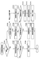
- FIG. 3 is a flowchart showing the charging / heating control process according to the embodiment of the present invention.
- FIG. 4 is a flowchart showing the heating policy calculation process of FIG.
- FIG. 5A is a flowchart showing the heating process during charging in FIG.
- FIG. 5B is a flowchart showing the heating process during charging in FIG.
- FIG. 6 is a flowchart showing the non-charging heating control process of FIG.
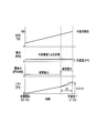
- FIG. 7 is a time chart showing an example of general parking charge in the electric vehicle of FIG. FIG.
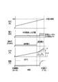
- FIG. 8 is a time chart showing an example in which an electric heater is used as a heat source of the heater core when the driver requests heating completion at the same time as charging completion in the electric vehicle of FIG.
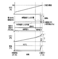
- FIG. 9 is a time chart showing an example in which the waste heat of the power generation device is used as a heat source of the heater core when the driver requests heating completion at the same time as charging completion in the electric vehicle of FIG.
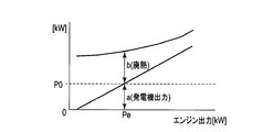
- FIG. 10 is a characteristic diagram showing the relationship between the generator output relative to the engine output and the waste heat available for heating according to the embodiment of the present invention.
- FIG. 1 is a schematic diagram showing an electric vehicle equipped with a power generation apparatus, which is a vehicle according to an embodiment of the present invention.
- a power generation device PGU in which the engine 10 that is an internal combustion engine and the generator 8 are combined is used as the power generation device, but the power generation device may be another power generation device such as a fuel cell power generation system.
- the drive motor 1 drives the electric vehicle.
- the inverter 2 receives power from the high-voltage battery 3 (corresponding to a battery) and / or the power generator PGU and supplies drive power to the drive motor 1.
- the high voltage battery 3 is a battery that can be charged by an internal power supply (power generation device PGU) or an external power supply EPS.
- the high voltage battery control device 17 detects and controls the state of the high voltage battery 3 and transmits and receives information to and from the vehicle controller 19 and the like which will be described later.
- the high-voltage battery 3 and the high-voltage battery control device 17 supply power for driving the drive motor 1, and also generate power generated by the generator 8 of the power generation device PGU and power regenerated when the drive motor 1 decelerates. Play a role to absorb.
- the high-power equipment cooling system CS1 is a system that circulates water through high-voltage components (high-power equipment) including the drive motor 1, the charger 5, the generator 8, the inverter 2, and the inverter 9 to cool these high-power equipment. At least the cooling water pump 4 and the high-power radiator 7 are provided. The cooling water pump 4 circulates water for cooling the high-power equipment, and the high-power radiator 7 cools water for cooling the high-power equipment.
- the charger 5 receives power from the external power source EPS and charges the high voltage battery 3.
- the connection device 6 is a plug for connecting the charger 5 to an external power source EPS that is system power.
- the external power source EPS may be a household outlet or a charging station dedicated to an electric vehicle.
- the generator 8 is combined with the engine 10 to generate power.
- the inverter 9 receives power from the high voltage battery 3 and drives the generator 8 when the engine 10 is turned as a load, for example.
- the engine 10 is an internal combustion engine for generating power.
- the engine cooling system CS2 is a system that circulates cooling water in the engine 10 and cools it, and includes at least a cooling water pump 13, an engine radiator 14, and a heater core 11.
- the cooling water pump 13 circulates the engine cooling water
- the engine radiator 14 cools the engine cooling water.
- the heater core 11 is a heat source for heating, and air for heating using one or both of the heat of the cooling water of the engine 10 (corresponding to the waste heat of the power generator PGU) and the heat of the electric heater 12 as a heat source. It is a structure that can be heated.
- the electric heater 12 is an electric heat source for heating with electric energy, and generates heat by electric power from an electric power source such as the external power source EPS, the high voltage battery 3, or the power generator PGU.
- the engine control device 15 is a control device for controlling the engine 10, and based on various sensor information and commands from a vehicle controller 19 described later, the fuel injection amount, intake air amount, ignition timing, etc. of the engine 10 are determined. Control the parameters.
- the generator control device 16 is a control device for controlling the generator 8, and based on a command from the vehicle controller 19 to be described later, the power generation state in which power is generated, and the power by turning the engine 10 as a load.
- the generator 8 is appropriately controlled according to the operating state such as the consumed state.
- the motor control device 18 is a motor control device that controls the drive motor 1.
- the motor control device 18 outputs power to the high-voltage battery 3 during a power running state in which torque is output based on a command from the vehicle controller 19 described later, or during deceleration.
- the drive motor 1 is controlled according to the operation state of the vehicle such as the regenerative state to be absorbed.
- the vehicle controller 19 includes, for example, an operation input from the driver, environmental information such as the outside air temperature detected by the outside air temperature detector 20, vehicle state such as vehicle speed, parking brake, park lock ON / OFF, and the above-described controls. Based on the signal from the device, the entire vehicle is controlled as a control unit.
- the vehicle controller 19 outputs a signal for driving the drive motor 1 to the motor control device 18 in response to a request from the driver, and the electric energy (SOC) of the high voltage battery 3 detected by the high voltage battery control device 17.
- SOC electric energy
- the engine 10 and the generator are connected via the engine control device 15 and the generator control device 16 so as to generate power so that the amount of electric power is appropriate for the operation state of the vehicle at that time and the future travel schedule. 8 is controlled.
- the vehicle controller 19 controls the charger 5 while monitoring the state of the high voltage battery 3 via the high voltage battery control device 17 when charging from the external power source EPS while the vehicle is parked. 3 is charged with appropriate power. Further, when there is a heating request from the driver, the vehicle controller 19 realizes an appropriate heating state by controlling the heater core 11 using the heat energy of the engine cooling water or the heat of the electric heater 12.
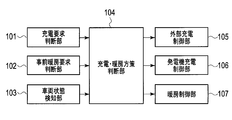
- FIG. 2 is a schematic diagram illustrating a control configuration in the electric generator-mounted electric vehicle according to the embodiment of the present invention.
- the charging request determination unit 101 determines the presence / absence of the driver's charging request and the content thereof.
- the pre-heating request determination unit 102 determines whether or not there is a pre-heating request from the driver and its contents (including the driver's pre-heating intention and the pre-heating completion scheduled time based thereon).
- the vehicle state detection unit 103 detects the state of the entire vehicle, for example, environmental information such as outside air temperature, parking brake, and park lock ON / OFF.
- the charging / heating policy determination unit 104 determines the charging or heating policy based on the determination content by the charge request determination unit 101, the determination content by the pre-heating request determination unit 102, and the determination content by the vehicle state detection unit 103. to decide.
- the external charging control unit 105 controls charging (external charging) using the external power source EPS based on the output of the charging / heating policy determination unit 104.
- the generator charging control unit 106 performs charging (generator charging) using the generator 8 based on the output of the charging / heating policy determination unit 104.
- the heating control unit 107 controls heating based on the output of the charging / heating policy determination unit 104.
- the electric generator-equipped electric vehicle is a vehicle that can be charged and heated by an external power source EPS, and that can be charged and heated by an internal power source such as a generator 8 (power generation device PGU) driven by the engine 10.
- an internal power source such as a generator 8 (power generation device PGU) driven by the engine 10.
- the vehicle controller 19 performs the charging / heating control process described below to achieve high efficiency and low cost of charging / heating, and is sufficient even when the outside air temperature is low. Realizes the heating.
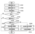
- FIG. 3 is a flowchart showing the charging / heating control process according to the embodiment of the present invention.
- the vehicle controller 19 reads the driver's operation, settings, etc. in step S1002 following step S1001. Specifically, the vehicle controller 19 reads a driver charging request in step S1001, and reads a driver heating request in step S1002.
- the driver operations, settings, and the like read in steps S1001 and S1002 include, for example, the next departure date and time, the indoor set temperature, and the like.
- step S ⁇ b> 1003 the vehicle controller 19 detects environmental information such as the outside air temperature, a vehicle state such as parking brake and park lock ON / OFF.
- step S1004 the vehicle controller 19 determines whether or not the vehicle is parked based on the vehicle state detected in step S1003. If it is determined that the vehicle is parked, the vehicle controller 19 advances the process to step S1005. If it is determined that the vehicle is not parked, the vehicle controller 19 ends the process.
- step S1005 the vehicle controller 19 determines whether there is a heating request from the operation, setting, etc. of the driver read in step S1002. If it is determined that there is a heating request, the vehicle controller 19 advances the process to step S1006, and if it is determined that there is no heating request, the process ends.
- step S1006 the vehicle controller 19 determines whether or not there is a charging request from the operation, setting, etc. of the driver read in step S1001. If there is a charge request, the vehicle controller 19 advances the process to step S1007, and if there is no charge request, advances the process to step S1009.
- step S1007 the vehicle controller 19 calculates a heating realization policy during charging, and in subsequent step S1008, performs the heating control during charging based on the heating policy calculated in step S1007, and ends the process.
- step S1009 the vehicle controller 19 calculates a heating realization policy during non-charging based on the determination result that there is no charge request in step S1006, and in the subsequent step S1010, based on the heating policy calculated in step S1009. Then, the heating control during non-charging is performed and the process is terminated.
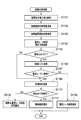
- FIG. 4 is a flowchart showing a heating policy calculation process according to the embodiment of the present invention. Specifically, the calculation of the heating policy performed in step S1007 and step S1009 in FIG.
- the vehicle controller 19 calculates the electric energy Q for responding to the heating request from the current indoor set temperature, outside air temperature, and the like.
- the vehicle controller 19 determines the amount of power generation (generator output) when performing waste heat heating (heating using waste heat of the power generation device PGU as a heat source of the heater core 11). It calculates from the characteristic of FIG. 10 mentioned later. Further, in the case of non-charging heating, the vehicle controller 19 cannot determine the operating point of power generation from the charged power, and therefore calculates the power generation amount based on the power and power amount that can be accepted by the battery at that time. .
- step S1103 the vehicle controller 19 calculates the duration T3 of waste heat heating required to supply the amount of heat required for heating by waste heat heating from the calculation results of step S1101 and step S1102.
- step S1103 the vehicle controller 19 starts waste heat heating based on the heating end time (heating completion scheduled time) determined based on the driver operation, settings, etc. read in step S1002, and T3. (Waste heat heating start time) is calculated. The details of the calculation will be described later.
- step S ⁇ b> 1104 the vehicle controller 19 calculates a duration T ⁇ b> 2 of electric heater heating (heating using the electric heater 12 as a heat source of the heater core 11) necessary for supplying the amount of heat necessary for heating by the electric heater 12.
- step S1104 the vehicle controller 19 calculates the time (electric heater heating start time) for starting electric heater heating based on the heating end time and T2.
- step S ⁇ b> 1105 the vehicle controller 19 determines whether heating can be completed with only the electric heater from conditions such as the heating capacity of the electric heater 12 and the outside air temperature detected by the outside air temperature detector 20. If it is determined that heating can be completed with only the electric heater 12, the vehicle controller 19 proceeds to step S1106, and if it is not possible, the process proceeds to step S1108. Under the extremely low temperature condition where the detected outside air temperature is lower than the predetermined temperature and it is difficult to achieve sufficient heating with only the electric heater 12, the vehicle controller 19 cannot complete the heating with only the electric heater 12. Judge and select waste heat heating.
- step S1106 the vehicle controller 19 uses only the electric heater 12 as the heat source of the heater core 11 (when the electric power from the external power source EPS is used as the heat source), and uses the waste heat of the power generation device PGU (the power generation device).
- the heating cost (energy cost) of the waste heat of PGU is used as a heat source. Examples of heating costs in each case (FIGS. 8 and 9) will be described later.
- the vehicle controller 19 functions as an energy cost calculation unit.
- step S1107 the vehicle controller 19 determines whether the heating cost of the electric heater 12 is higher than the cost of waste heat heating. If the heating cost of the electric heater 12 is higher than the cost of waste heat heating, the process is performed. The process proceeds to step S1108. If the heating cost in the electric heater 12 is lower than the cost of waste heat heating, the vehicle controller 19 advances the process to step S1109, selects heating in the electric heater 12, and ends the process.
- step S1108 when the vehicle controller 19 performs heating using the waste heat of the power generation device PGU, there is a constraint on power generation such as the need to suppress the amount of power generation to suppress the sound generated by the generator. When the power generation performance is to be suppressed, the constraint condition is calculated.
- step S1110 the vehicle controller 19 determines whether or not heating can be completed with waste heat heating within the range of the restriction condition obtained in step S1108.
- the vehicle controller 19 advances the process to step S1111 to select waste heat heating by the power generator PGU and ends the process.
- the power generation restriction condition may be set as appropriate according to the thermal environment at that time, or may be set in advance.
- the vehicle controller 19 functions as a power generation performance suppression determination unit. If it is determined in step S1110 that heating cannot be completed with waste heat heating within the range of the constraint obtained in step S1108, the vehicle controller 19 advances the process to step S1112 to The process is terminated by selecting to use together with the electric heater heating.
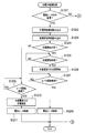
- the vehicle controller 19 determines whether heating using only the electric heater 12 is selected in step S1201. If selected, the vehicle controller 19 advances the process to step S1202, and if not selected, advances the process to step S1212.
- step S1202 the vehicle controller 19 reads the start time of charging, and in step S1203, the start time of heating in the electric heater 12 calculated in the flowchart of FIG. 4 is read.
- step S1204 the vehicle controller 19 determines whether or not the start of charging is the start of charging and the start of heating.
- step S1205. If the start of charging is the first, the process proceeds to step S1205. If the start of charging is not the first, the process is performed. Advances to step S1209. In step S1205, the vehicle controller 19 determines whether or not it is time to start charging. If the charging start time has not yet been reached, step S1205 is repeated as it is. If the charging start time has been reached, the process proceeds to step S1205. The process proceeds to S1206. In step S1206, the vehicle controller 19 starts charging with the external power source EPS, and then proceeds to step S1207.
- step S1207 the vehicle controller 19 determines whether it is the start time of electric heater heating. If the electric heater heating start time has not yet been reached, the vehicle controller 19 repeats step S1207 as it is, and if the electric heater heating start time has been reached, the process proceeds to step S1208. In step S1208, the vehicle controller 19 starts heating control with the electric heater 12, and thereafter ends the process. If it is determined in step S1204 that charging has not started first, the vehicle controller 19 determines in step S1209 whether it is the start time of electric heater heating. If the electric heater heating start time has not yet been reached, the vehicle controller 19 repeats step S1209 as it is, and if the electric heater heating start time has been reached, the process proceeds to step S1210. In step S1210, the vehicle controller 19 starts charging with the external power source EPS, starts heating control with the electric heater 12 in subsequent step S1211, and ends the process.
- step S1210 the vehicle controller 19 starts charging with the external power source EPS, starts heating control with the electric heater 12 in subsequent step S1211, and ends the
- step S1201 When heating with only the electric heater 12 is not selected in step S1201, the vehicle controller 19 advances the process to step S1212.
- step S1212 the vehicle controller 19 determines whether or not heating with only waste heat (power generation waste heat) of the power generation device PGU is selected, and if so, the process proceeds to step S1213 to select it. If not, the process proceeds to step S1221.
- step S1213 the vehicle controller 19 reads the charging start time.
- step S1214 the vehicle controller 19 reads the heating start time in the waste heat heating calculated in the flowchart of FIG.
- step S1215 the vehicle controller 19 determines whether or not the start of charging is first between the start of charging and the start of heating. If the start of charging is first, the process proceeds to step S1216.
- step S1216 the vehicle controller 19 determines whether or not it is time to start charging. If the charging start time has not yet been reached, step S1216 is repeated, and if the charging start time has been reached, the process proceeds to step S1216. The process proceeds to S1217. In step S1217, the vehicle controller 19 starts charging with the external power source EPS, and then proceeds to step S1218.
- step S1218 the vehicle controller 19 determines whether it is the start time of waste heat heating of the power generator PGU. If the waste heat heating start time has not yet been reached, the vehicle controller 19 repeats step S1218 as it is, and if the waste heat heating start time has been reached, the process proceeds to step S1219.
- step S1219 the vehicle controller 19 starts power generation control in the generator 8, starts heating control using the waste heat of the power generator PGU in subsequent step S1220, and ends the process. If heating by only the waste heat of the power generator PGU is not selected in step S1212, the vehicle controller 19 advances the process to step S1221, reads the charging start time in step S1221, and in FIG. The heating start time in the waste heat heating calculated in the flowchart is read.
- step S1223 the vehicle controller 19 determines whether the charging start is first among the charging start and heating start. If the charging start is first, the process proceeds to step S1224. If the charging start is not first, Then, the process proceeds to step S1226.
- step S1224 the vehicle controller 19 determines whether or not it is time to start charging. If the charging start time has not yet been reached, step S1224 is repeated as it is. If the charging start time has been reached, the process proceeds to step S1224. Proceed to S1225. In step S1225, the vehicle controller 19 starts charging with the external power source EPS, and then proceeds to step S1226. In step S1226, the vehicle controller 19 determines whether or not the start time of the waste heat heating of the power generator PGU. If the start time of the waste heat heating has not yet been reached, the vehicle controller 19 repeats step S1226 as it is to start the waste heat heating. If the time has come, the process proceeds to step S1227.
- step S1227 the vehicle controller 19 starts power generation control in the generator 8, and then starts heating control using the waste heat of the power generator PGU in step S1228, and heating in the electric heater 12 used in combination in step S1229. Control is also started and the process is terminated.
- FIG. 6 is a flowchart showing a non-charging heating control process according to the embodiment of the present invention. Specifically, it is a flowchart showing the procedure of step S1010 in the flowchart of FIG.
- the vehicle controller 19 determines in step S1301 whether or not heating by only the electric heater 12 is selected, and if it is selected, the process proceeds to step S1302. The process proceeds to step S1305.
- the vehicle controller 19 reads the heating start time in the electric heater 12 calculated in the flowchart of FIG.
- step S1303 the vehicle controller 19 determines whether or not the electric heater heating start time has come.
- step S1303 is repeated as it is, and the electric heater heating start time has come. If so, the process advances to step S1304.
- step S1304 the vehicle controller 19 starts heating control with the electric heater 12, and thereafter ends the process.
- step S1305 the vehicle controller 19 determines whether or not heating with only the waste heat of the power generator PGU is selected. If selected, the process proceeds to step S1306. If not selected, The process proceeds to step S1310. In step S1306, the vehicle controller 19 reads the heating start time in the waste heat heating calculated in the flowchart of FIG.
- step S1307 the vehicle controller 19 determines whether it is the start time of the waste heat heating of the power generator PGU. If the start time of the waste heat heating is not yet reached, the vehicle controller 19 repeats step S1307 and starts the waste heat heating. If the time has come, the process proceeds to step S1308. In step S1308, the vehicle controller 19 starts power generation control in the generator 8, starts heating control using the waste heat of the power generator PGU in subsequent step S1309, and ends the process. When heating with only the waste heat of the power generator PGU is not selected in step S1305, the vehicle controller 19 advances the process to step S1310, and in step S1310, heating with waste heat heating calculated in the flowchart of FIG. Read the start time.
- step S1311 the vehicle controller 19 determines whether it is the start time of the waste heat heating of the power generator PGU. If the start time of the waste heat heating is not yet reached, the vehicle controller 19 repeats step S1311 as it is to start the waste heat heating. If the time has come, the process proceeds to step S1312. In step S1312, the vehicle controller 19 starts power generation control in the generator 8, and then starts heating control using waste heat of the power generator PGU in step S1313, and heating in the electric heater 12 used in combination in step S1314. Control is also started and the process is terminated.
- FIG. 7 is a time chart showing an example in which general charging during parking is performed in the electric vehicle equipped with the power generation apparatus according to the present embodiment.
- the vehicle controller 19 charges the high-voltage battery 3 at 23:
- the battery charger 5 is controlled so as to start at 00 and be completed at 7:00 in the morning of the next day (departure date).
- the high voltage battery 3 is charged at a constant charge power P0.
- the grid power includes, for example, nighttime power and relatively high daytime power whose unit price of electricity is relatively low. Therefore, when charging power P0 is constant, the integrated energy cost (electricity cost) is the lowest figure in FIG.
- the integrated energy cost changes at a relatively high rate of increase after switching from nighttime power to daytime power (during time T0). Then, when the integrated energy cost finally reaches the cost A, the requested charging is completed.
- FIG. 8 is a time chart showing an example in which the electric heater 12 is used as the heat source of the heater core 11 when the driver requests the completion of heating at the same time as the completion of charging in the electric vehicle equipped with the power generation apparatus according to the present embodiment. is there.
- the vehicle controller 19 sets the next morning 7:00 in advance based on the driver's preheating intention. Judgment is made as the scheduled heating completion time, and charging of the high voltage battery 3 is started from 23:00 on the day (the day before the departure date) and is controlled to be completed at 7:00 on the next morning (morning on the departure day). To do.
- the integrated energy cost (electricity cost) finally becomes a cost B higher than the cost A.
- the capacity Ph of the electric heater 12 is It is set to be smaller than that of an electric vehicle not equipped with a generator.
- the desired heating is realized only by the electric heater 12 during parking, it is necessary to perform the heating for a relatively long time (T2), and the amount of heat radiated to the outside air during that time becomes relatively large.
- the efficiency is relatively low, and the accumulated energy cost (electricity cost) B is a relatively high value.
- FIG. 9 shows an example in which the waste heat of the power generator PGU is used as the heat source of the heater core 11 when the driver requests the completion of heating at the same time as the completion of charging in the electric generator-mounted electric vehicle according to the present embodiment. It is a time chart. In this case, by using the waste heat of the generator 8 and the engine 10 (engine cooling water) instead of the electric heater 12, the time required for heating is shortened, and only the time T3 ( ⁇ T2) than the scheduled pre-heating completion time. It is only necessary to perform heating for a time T3 shorter than the time T2 from the previous time point.
- the generator 8 when the generator 8 is driven by the engine 10 using gasoline as a fuel to generate electric power and a predetermined amount of electric power is obtained, the fuel cost required to obtain the same amount of electric power is compared with that shown in FIG. As shown in 9, the fuel cost is often higher.
- the charging power P0 originally obtained from the external power source EPS is generated by the generator 8 driven by the engine 10 and the waste heat generated at the time of power generation is used for heating, the heating can be provided only by the fuel cost for charging. This increases the number of scenes where the cost is reduced and shortens the time required for heating, which is advantageous as a heat dissipation measure and can reduce the total energy cost.
- the acquisition method of information such as a fuel unit price and an electricity bill unit price, is not specifically limited, For example, it is possible to acquire separately using a communication apparatus etc.
- FIG. 10 shows the relationship between the generator output relative to the engine output and the waste heat available for heating.
- a high voltage battery 3 (battery) that can be charged by the external power source EPS, a power generation device PGU that can charge the high voltage battery 3, and an external power source EPS, the high voltage battery 3, or the power generation device PGU, for example.
- An electric heater 12 that generates heat by electric power from the power source, a heater core 11 that heats the waste heat of the power generator PGU or the air by the electric heater 12, and a waste heat of the power generator PGU and the electric heater 12 as a heat source of the heater core 11 when parking.
- the vehicle controller 19 (control part) which performs control which uses selectively is provided. Thereby, sufficient heating effect can be acquired by heating using the waste heat of power generator PGU which has energy larger than electric heater 12.
- the vehicle controller 19 operates the power generation device PGU and uses the waste heat of the power generation device PGU as a heat source for the heater core 11. Thereby, the heating effect can be acquired in a short time.
- the vehicle controller 19 charges the high voltage battery 3 with the power generator PGU. Thereby, it is possible to perform heating using the waste heat that is the loss energy at that time while performing the necessary charging by the generator 8, and it is possible to efficiently obtain a sufficient heating effect in a short time.
- a pre-heating request determination unit 102 that determines a pre-heating completion scheduled time based on the driver's pre-heating intention is provided, and the vehicle controller 19 operates the power generator PGU a predetermined time before the pre-heating completion scheduled time ( (See step S1103).
- step S1106 the vehicle controller 19 calculates an energy cost when the waste heat of the power generator PGU is used as a heat source and an energy cost when the electric power from the external power source EPS is used as a heat source (energy cost).
- the calculation unit controls the heat source so that the calculated energy cost becomes smaller. Thereby, sufficient heating effect can be acquired, aiming at cost reduction by selecting the heat source with the smaller energy cost.
- the outside air temperature detector 20 that detects the outside air temperature is provided, and the vehicle controller 19 uses the waste heat of the power generator PGU as the heat source of the heater core 11 when the detected outside air temperature is lower than the predetermined temperature in step S1105. . Thereby, even if it is a case where the outside air temperature is low and it is difficult to achieve sufficient heating with the electric heater 12, it is possible to obtain a sufficient heating effect by selecting waste heat heating. .
- step S1108 the vehicle controller 19 determines whether or not to suppress the power generation performance of the power generation device PGU (power generation performance suppression determination unit). If it is determined in step S1110 to suppress the power generation performance, the heater core The waste heat of the power generator PGU and the electric heater 12 are used in combination as the heat source 11. Thus, the capacity of the electric heater 12 is not sufficient, and both heat sources are selected even when it is necessary to suppress the performance of the waste heat heating of the power generator PGU due to constraints on noise and the like. Thus, even when the outside air temperature is low, a sufficient heating effect can be obtained while suppressing the generated sound.
- the heating by the waste heat of the electric heater 12 and the power generator PGU described in the present application naturally includes not only warming the driver's room but also warming up system components (for example, a battery). Yes.
- the pre-air conditioning to which the vehicle control device or the control method according to the present invention can be applied is not limited to pre-heating, and naturally includes pre-cooling.
- the concept of the present invention is applied even to a control device that determines whether to use electric energy or kinetic energy of an engine that is a power generator PGU as a power energy source of a compressor used in a refrigeration cycle. Can be controlled.
- an electric motor and an engine may be connected to the compressor via a clutch or the like, and the power source may be switched as appropriate.
- control device and the control method for a vehicle in order to perform control to selectively use the waste heat of the power generation device and the electric heater as a heat source of the heater core at the time of parking, not only the electric heater at the time of parking, Air can be heated using the waste heat of the power generation device as a heat source of the heater core, and sufficient heating can be achieved.
Landscapes
- Engineering & Computer Science (AREA)
- Chemical & Material Sciences (AREA)
- Physics & Mathematics (AREA)
- Thermal Sciences (AREA)
- Mechanical Engineering (AREA)
- Manufacturing & Machinery (AREA)
- Chemical Kinetics & Catalysis (AREA)
- Electrochemistry (AREA)
- General Chemical & Material Sciences (AREA)
- Combustion & Propulsion (AREA)
- Air-Conditioning For Vehicles (AREA)
- Electric Propulsion And Braking For Vehicles (AREA)
Abstract
外部電源(EPS)により充電可能な電池(3)と、電池(3)に対して充電可能な発電装置(PGU)と、電力源からの電力により発熱する電気ヒータ(12)と、発電装置(PGU)の廃熱又は電気ヒータ(12)により空気を加熱するヒータコア(11)と、駐車時に、ヒータコア(11)の熱源として発電装置(PGU)の廃熱と電気ヒータ(12)とを選択的に用いる制御を行う制御部(19)とを備えた車両の制御装置であって、上記により、事前暖房において、十分な暖房を達成することができる。
Description
本発明は、電気的な空調用熱源を備えた車両の制御装置及び制御方法に関する。
特許文献1は、電気的加熱手段等を用いた空調装置を備えた電気自動車において、充電中に事前暖房を行う技術を開示している。
しかしながら、上記技術では、電源電力のみを用いて事前暖房を行っていたため、例えば外気温が低い場合に空気を加熱するエネルギが不足することで、十分な暖房ができないおそれがあった。
本発明は、上記問題に着目してなされたもので、十分な暖房を達成することが可能な車両の制御装置を提供することを目的とする。
本発明の第一の態様は、車両の制御装置である。この制御装置は、外部電源により充電可能な電池と、電池に対して充電可能な発電装置と、電力源からの電力により発熱する電気ヒータと、発電装置の廃熱又は電気ヒータにより空気を加熱するヒータコアと、駐車時に、ヒータコアの熱源として発電装置の廃熱と電気ヒータとを選択的に用いる制御を行う制御部と、を備える。
本発明の第二の態様は、車両の制御方法である。この制御方法は、外部電源により充電可能な電池と、電池に対して充電可能な発電装置と、電力源からの電力により発熱する電気ヒータと、発電装置の廃熱又は電気ヒータにより空気を加熱するヒータコアと、を設け、駐車時に、ヒータコアの熱源として発電装置の廃熱と電気ヒータとを選択的に用いる制御を行う。
図1は、本発明の実施形態にかかる車両である発電装置搭載型電気自動車を表す概略図である。ここでは発電装置として、内燃機関であるエンジン10と発電機8とを組み合わせた発電装置PGUを使用しているが、発電装置は、燃料電池発電システムなどの他の発電装置であってもよい。駆動モータ1は、上記電気自動車を駆動する。インバータ2は、高電圧バッテリ3(電池に相当)及び/又は発電装置PGUからの電力を受けて、駆動モータ1に駆動電力を供給する。高電圧バッテリ3は、内部電源(発電装置PGU)又は外部電源EPSによって充電することが可能な電池である。高電圧バッテリ制御装置17は、高電圧バッテリ3の状態の検知、制御を行うと共に、後述する車両コントローラ19等と情報の送受信を行う。高電圧バッテリ3及び高電圧バッテリ制御装置17は、駆動モータ1を駆動するための電力を供給し、また、発電装置PGUの発電機8が発電した電力や駆動モータ1が減速時に回生した電力を吸収する役割を担う。
強電機器冷却系統CS1は、駆動モータ1、充電器5、発電機8、インバータ2、インバータ9を含む高電圧部品(強電機器)などに水を循環させて、これら強電機器を冷却する系統であり、少なくとも冷却水ポンプ4と、強電用ラジエータ7とを備える。冷却水ポンプ4は、上記強電機器を冷却するための水を循環させ、強電用ラジエータ7は、上記強電機器を冷却するための水を冷却する。
充電器5は、外部電源EPSからの電力を受けて、高電圧バッテリ3を充電する。接続装置6は、充電器5を系統電力である外部電源EPSに接続するためのプラグである。外部電源EPSは、家庭用コンセントでもよいし、電気自動車専用の充電スタンドであってもよい。
発電機8は、エンジン10と組み合わされて発電を行う。インバータ9は、例えば、エンジン10を負荷として回す場合に、高電圧バッテリ3からの電力を受けて、発電機8を駆動する。エンジン10は、発電を行うための内燃機関である。
発電機8は、エンジン10と組み合わされて発電を行う。インバータ9は、例えば、エンジン10を負荷として回す場合に、高電圧バッテリ3からの電力を受けて、発電機8を駆動する。エンジン10は、発電を行うための内燃機関である。
エンジン冷却系統CS2は、エンジン10に冷却水を循環させて、これを冷却する系統であり、少なくとも冷却水ポンプ13と、エンジン用ラジエータ14と、ヒータコア11とを備える。冷却水ポンプ13は、エンジン冷却水を循環させ、エンジン用ラジエータ14は、エンジン冷却水を冷却する。
ヒータコア11は、暖房を行うための熱源であり、エンジン10の冷却水の熱(発電装置PGUの廃熱に相当)と電気ヒータ12の熱との一方または両方を熱源として利用して暖房用空気を加熱することが可能な構造となっている。電気ヒータ12は、電気エネルギで暖房を行うための電気的熱源であり、例えば、外部電源EPS、高電圧バッテリ3、または発電装置PGU等の電力源からの電力により発熱する。
エンジン制御装置15は、エンジン10を制御するための制御装置であり、種々のセンサ情報や後述する車両コントローラ19からの指令に基づいて、エンジン10の燃料噴射量、吸入空気量、点火時期などのパラメータを制御する。
発電機制御装置16は、発電機8を制御するための制御装置であり、後述する車両コントローラ19からの指令に基づいて、電力を発電する発電状態や、エンジン10を負荷として回すことで電力を消費する消費状態などの運転状態に応じて、発電機8を適切に制御する。
モータ制御装置18は、駆動モータ1を制御するモータ制御装置であり、後述する車両コントローラ19からの指令に基づいて、トルクを出力して走行する力行状態や、減速時にエネルギを高電圧バッテリ3に吸収する回生状態などの車両の動作状態に応じて、駆動モータ1を制御する。
発電機制御装置16は、発電機8を制御するための制御装置であり、後述する車両コントローラ19からの指令に基づいて、電力を発電する発電状態や、エンジン10を負荷として回すことで電力を消費する消費状態などの運転状態に応じて、発電機8を適切に制御する。
モータ制御装置18は、駆動モータ1を制御するモータ制御装置であり、後述する車両コントローラ19からの指令に基づいて、トルクを出力して走行する力行状態や、減速時にエネルギを高電圧バッテリ3に吸収する回生状態などの車両の動作状態に応じて、駆動モータ1を制御する。
車両コントローラ19は、例えば、ドライバからの操作入力と、外気温検出器20により検出された外気温などの環境情報、車速、パーキングブレーキ、パークロックのON/OFFなどの車両状態と、上記各制御装置からの信号とに基づき、制御部として車両全体を制御する。車両コントローラ19は、ドライバからの要求に応じて駆動モータ1を駆動する信号をモータ制御装置18へ出力するとともに、高電圧バッテリ制御装置17により検知された高電圧バッテリ3の電力量(SOC)などを読み取る。そして、この電力量がそのときの車両の動作状態や今後の走行予定に対して適切となるような発電を行うように、エンジン制御装置15や発電機制御装置16を介してエンジン10や発電機8を制御する。
また、車両コントローラ19は、車両駐車中に外部電源EPSから充電する場合に、高電圧バッテリ制御装置17を介して高電圧バッテリ3の状態を監視しながら、充電器5を制御して高電圧バッテリ3に適正な電力を充電する。また、車両コントローラ19は、ドライバからの暖房要求がある場合には、エンジン冷却水の熱エネルギや電気ヒータ12の熱を用いて、ヒータコア11を制御することで適正な暖房状態を実現する。
また、車両コントローラ19は、車両駐車中に外部電源EPSから充電する場合に、高電圧バッテリ制御装置17を介して高電圧バッテリ3の状態を監視しながら、充電器5を制御して高電圧バッテリ3に適正な電力を充電する。また、車両コントローラ19は、ドライバからの暖房要求がある場合には、エンジン冷却水の熱エネルギや電気ヒータ12の熱を用いて、ヒータコア11を制御することで適正な暖房状態を実現する。
図2は、本発明の実施形態にかかる発電装置搭載型電気自動車における制御構成を表す概略図である。充電要求判断部101は、ドライバの充電要求の有無とその内容を判断する。事前暖房要求判断部102は、ドライバからの事前暖房の要求の有無およびその内容(ドライバの事前暖房意図およびそれに基づく事前暖房完了予定時刻を含む)を判断する。車両状態検知部103は、例えば、外気温などの環境情報、パーキングブレーキ、パークロックのON/OFFなど車両全体の状態を検知する。
充電・暖房方策判断部104は、充電要求判断部101による判断内容と、事前暖房要求判断部102による判断内容と、車両状態検知部103による判断内容と、に基づいて、充電や暖房の方策を判断する。外部充電制御部105は、充電・暖房方策判断部104の出力に基づいて外部電源EPSを用いた充電(外部充電)の制御を行う。発電機充電制御部106は、充電・暖房方策判断部104の出力に基づいて発電機8を用いた充電(発電機充電)を行う。暖房制御部107は、充電・暖房方策判断部104の出力に基づいて暖房の制御を行う。
充電・暖房方策判断部104は、充電要求判断部101による判断内容と、事前暖房要求判断部102による判断内容と、車両状態検知部103による判断内容と、に基づいて、充電や暖房の方策を判断する。外部充電制御部105は、充電・暖房方策判断部104の出力に基づいて外部電源EPSを用いた充電(外部充電)の制御を行う。発電機充電制御部106は、充電・暖房方策判断部104の出力に基づいて発電機8を用いた充電(発電機充電)を行う。暖房制御部107は、充電・暖房方策判断部104の出力に基づいて暖房の制御を行う。
発電装置搭載型電気自動車は、外部電源EPSによる充電及び暖房を可能とし、かつ、エンジン10で駆動する発電機8(発電装置PGU)などの内部電源による充電及び暖房を可能とした車両である。このような車両では、外部電源EPSを用いるより内部電源を用いるほうが高効率となる場合でも、常に外部電源EPSにより充電及び暖房を実行することで、充電効率又は暖房効率の低下やエネルギコストの上昇を招くことがあった。また、電源電力のみを用いて事前暖房を行うと、例えば外気温が低い場合、空気を加熱するエネルギが不足することで十分な暖房ができないおそれがあった。
本実施形態では、車両コントローラ19において、以下に述べる充電暖房制御処理を実施することで、充電・暖房の高効率化及び低コスト化を達成し、また、外気温が低い場合であっても十分な暖房を実現している。
本実施形態では、車両コントローラ19において、以下に述べる充電暖房制御処理を実施することで、充電・暖房の高効率化及び低コスト化を達成し、また、外気温が低い場合であっても十分な暖房を実現している。
<充電暖房制御処理>
図3は、本発明の実施形態にかかる充電暖房制御処理を表すフローチャートである。
充電暖房制御処理では、車両コントローラ19は、ステップS1001と続くステップS1002で、ドライバの操作、設定等を読み込む。具体的には、車両コントローラ19は、ステップS1001でドライバの充電要求を読み込み、ステップS1002で、ドライバの暖房要求を読み込む。ステップS1001およびステップS1002で読み込まれるドライバの操作、設定等には、例えば、次回の出発日時、室内の設定温度等が含まれる。ステップS1003では、車両コントローラ19は、外気温などの環境情報、パーキングブレーキ、パークロックのON/OFFなどの車両状態を検出する。
ステップS1004では、車両コントローラ19は、ステップS1003で検出した車両状態に基づいて、車両が駐車中であるかどうかを判断する。駐車中であると判断した場合は、車両コントローラ19は、処理をステップS1005へ進め、駐車中でないと判断した場合はそのまま処理を終了する。
ステップS1005では、車両コントローラ19は、ステップS1002で読み込んだドライバの操作、設定等から、暖房要求があるかどうかを判断する。暖房要求があると判断した場合は、車両コントローラ19は、処理をステップS1006へ進め、暖房要求が無いと判断した場合はそのまま処理を終了する。
ステップS1006では、車両コントローラ19は、ステップS1001で読み込んだドライバの操作、設定等から、充電要求があるかどうかを判断する。充電要求がある場合は、車両コントローラ19は、処理をステップS1007へ進め、充電要求が無い場合は処理をステップS1009へ進める。
ステップS1007では、車両コントローラ19は、充電中の暖房の実現方策を演算し、続くステップS1008で、ステップS1007で演算した暖房方策に基づいて充電中の暖房制御を実施して、処理を終了する。
ステップS1006では、車両コントローラ19は、ステップS1001で読み込んだドライバの操作、設定等から、充電要求があるかどうかを判断する。充電要求がある場合は、車両コントローラ19は、処理をステップS1007へ進め、充電要求が無い場合は処理をステップS1009へ進める。
ステップS1007では、車両コントローラ19は、充電中の暖房の実現方策を演算し、続くステップS1008で、ステップS1007で演算した暖房方策に基づいて充電中の暖房制御を実施して、処理を終了する。
ステップS1009では、車両コントローラ19は、ステップS1006で充電要求が無いと判断した結果に基づいて、非充電中の暖房の実現方策を演算し、続くステップS1010で、ステップS1009で演算した暖房方策に基づいて非充電中の暖房制御を実施して、処理を終了する。
<暖房方策演算処理>
図4は、本発明の実施形態にかかる暖房方策演算処理を表すフローチャートである。具体的には、図3のステップS1007、ステップS1009で行う暖房方策の演算を表す。
暖房方策演算処理では、車両コントローラ19は、ステップS1101で、現在の室内設定温度、外気温等から、暖房要求に対応するための電力量Qを演算する。
ステップS1102では、充電中暖房の場合には、車両コントローラ19は、廃熱暖房(ヒータコア11の熱源として発電装置PGUの廃熱を利用する暖房)を行う場合の発電量(発電機出力)を、後述する図10の特性から演算する。また、非充電中暖房の場合には、車両コントローラ19は、充電電力から発電の動作点を決めることができないため、そのときのバッテリ受け入れ可能な電力や電力量に基づいて、発電量を演算する。
ステップS1103では、車両コントローラ19は、ステップS1101とステップS1102の演算結果から、暖房に必要な熱量を廃熱暖房で供給するために必要な廃熱暖房の継続時間T3を演算する。また、ステップS1103では、車両コントローラ19は、ステップS1002で読み込んだドライバの操作、設定等に基づいて定められる暖房終了時刻(暖房完了予定時刻)とT3とに基づいて、廃熱暖房を開始する時刻(廃熱暖房開始時期)を演算する。演算内容については後述する。
ステップS1104では、車両コントローラ19は、暖房に必要な熱量を電気ヒータ12で供給するために必要な電気ヒータ暖房(ヒータコア11の熱源として電気ヒータ12を利用する暖房)の継続時間T2を演算する。また、ステップS1104では、車両コントローラ19は、上記暖房終了時刻とT2とに基づいて、電気ヒータ暖房を開始する時刻(電気ヒータ暖房開始時期)を演算する。
ステップS1105では、車両コントローラ19は、電気ヒータ12の暖房能力、外気温検出器20で検出した外気温等の条件から、電気ヒータのみで暖房を完了することが可能であるかどうかを判断する。電気ヒータ12のみで暖房を完了することが可能であると判断した場合は、車両コントローラ19は、処理をステップS1106へ進め、可能でないと判断した場合は、処理をステップS1108へ進める。検出した外気温が所定温度より低く、電気ヒータ12のみでは十分な暖房を実現することが難しい極低温の条件下では、車両コントローラ19は、電気ヒータ12のみで暖房を完了させることが可能でないと判断し、廃熱暖房を選択する。
ステップS1106では、車両コントローラ19は、ヒータコア11の熱源として電気ヒータ12のみを利用した場合(外部電源EPSからの電力を熱源とした場合)と、発電装置PGUの廃熱を利用した場合(発電装置PGUの廃熱を熱源とした場合)の暖房コスト(エネルギコスト)を演算する。それぞれの場合における暖房コストの例(図8,9)については後述する。このステップS1106の処理において、車両コントローラ19はエネルギコスト演算部として機能する。
ステップS1107では、車両コントローラ19は、電気ヒータ12での暖房コストが廃熱暖房のコストより高いかどうかを判断し、電気ヒータ12での暖房コストが廃熱暖房のコストより高い場合は、処理をステップS1108へ進める。また、電気ヒータ12での暖房コストが廃熱暖房のコストより安い場合は、車両コントローラ19は、処理をステップS1109へ進め、電気ヒータ12での暖房を選択し、処理を終了する。
ステップS1108では、車両コントローラ19は、発電装置PGUの廃熱を利用して暖房を行う場合において、発電機が発する音を抑えるために発電量を抑制する必要があるなど発電に制約条件がある場合(すなわち、発電性能を抑制する場合)には、その制約条件を演算する。ステップS1110では、車両コントローラ19は、ステップS1108で求めた制約条件の範囲内の廃熱暖房で、暖房を完了することが可能かどうかを判断する。ここで、可能であると判断した場合には、車両コントローラ19は、処理をステップS1111へ進め、発電装置PGUによる廃熱暖房を選択して、処理を終了する。上記発電の制約条件は、そのときの熱環境等に応じて適宜設定してもよいし、予め設定してもよい。これらステップS1108,S1110の処理において、車両コントローラ19は発電性能抑制判断部として機能する。
ステップS1110で、ステップS1108で求めた制約条件の範囲内の廃熱暖房で、暖房を完了することが可能でないと判断した場合は、車両コントローラ19は、処理をステップS1112へ進め、廃熱暖房と電気ヒータ暖房とを併用することを選択して、処理を終了する。
<充電中暖房処理>
図5Aおよび図5Bは、本発明の実施形態にかかる充電中暖房処理を表すフローチャートである。具体的には、図3のフローチャートのステップS1008の手続きを表すフローチャートである。
充電中暖房処理では、車両コントローラ19は、ステップS1201で、電気ヒータ12のみでの暖房を選択しているかどうかを判断する。選択している場合は、車両コントローラ19は、処理をステップS1202へ進め、選択していない場合は、処理をステップS1212へ進める。
ステップS1202では、車両コントローラ19は、充電の開始時期を読み込み、ステップS1203では、図4のフローチャートで演算した電気ヒータ12での暖房の開始時期を読み込む。
ステップS1204では、車両コントローラ19は、充電開始と暖房開始とで充電開始が先かどうかを判断し、充電開始が先の場合は、処理をステップS1205へ進め、充電開始が先でない場合は、処理をステップS1209に進める。
ステップS1205では、車両コントローラ19は、充電開始の時期となっているかどうかを判断し、まだ充電開始時期に至っていない場合は、そのままステップS1205を繰り返し、充電開始時期に至っている場合は、処理をステップS1206へ進める。
ステップS1206では、車両コントローラ19は、外部電源EPSでの充電を開始し、その後、処理をステップS1207へ進める。
ステップS1207では、車両コントローラ19は、電気ヒータ暖房の開始時期となっているかどうかを判断する。まだ電気ヒータ暖房開始時期に至っていない場合は、車両コントローラ19は、そのままステップS1207を繰り返し、電気ヒータ暖房開始時期に至っている場合は、処理をステップS1208へ進める。ステップS1208では、車両コントローラ19は、電気ヒータ12での暖房制御を開始し、その後処理を終了する。
ステップS1204で充電開始が先でないと判断した場合には、車両コントローラ19は、ステップS1209で電気ヒータ暖房の開始時期となっているかどうかを判断する。まだ電気ヒータ暖房開始時期に至っていない場合は、車両コントローラ19は、そのままステップS1209を繰り返し、電気ヒータ暖房開始時期に至っている場合は、処理をステップS1210へ進める。ステップS1210では、車両コントローラ19は、外部電源EPSでの充電を開始し、続くステップS1211で電気ヒータ12での暖房制御を開始して、処理を終了する。
ステップS1204で充電開始が先でないと判断した場合には、車両コントローラ19は、ステップS1209で電気ヒータ暖房の開始時期となっているかどうかを判断する。まだ電気ヒータ暖房開始時期に至っていない場合は、車両コントローラ19は、そのままステップS1209を繰り返し、電気ヒータ暖房開始時期に至っている場合は、処理をステップS1210へ進める。ステップS1210では、車両コントローラ19は、外部電源EPSでの充電を開始し、続くステップS1211で電気ヒータ12での暖房制御を開始して、処理を終了する。
ステップS1201で電気ヒータ12のみでの暖房を選択してない場合は、車両コントローラ19は、処理をステップS1212へ進める。ステップS1212では、車両コントローラ19は、発電装置PGUの廃熱(発電廃熱)のみでの暖房を選択しているかどうかを判断し、選択している場合は、処理をステップS1213へ進め、選択していない場合は、処理をステップS1221へ進める。
ステップS1213では、車両コントローラ19は、充電の開始時期を読み込み、ステップS1214では、図4のフローチャートで演算した廃熱暖房での暖房開始時期を読み込む。
ステップS1215では、車両コントローラ19は、充電開始と暖房開始とで充電開始が先かどうかを判断し、充電開始が先の場合は、処理をステップS1216へ進め、充電開始が先でない場合は、処理をステップS1218に進める。
ステップS1216では、車両コントローラ19は、充電開始の時期となっているかどうかを判断し、まだ充電開始時期に至っていない場合は、そのままステップS1216を繰り返し、充電開始時期に至っている場合は、処理をステップS1217へ進める。
ステップS1217では、車両コントローラ19は、外部電源EPSでの充電を開始し、その後、処理をステップS1218へ進める。
ステップS1218では、車両コントローラ19は、発電装置PGUの廃熱暖房の開始時期となっているかどうかを判断する。まだ廃熱暖房開始時期に至っていない場合は、車両コントローラ19は、そのままステップS1218を繰り返し、廃熱暖房開始時期に至っている場合は、処理をステップS1219へ進める。ステップS1219では、車両コントローラ19は、発電機8での発電制御を開始し、続くステップS1220で発電装置PGUの廃熱を利用した暖房制御を開始して、処理を終了する。
ステップS1212で発電装置PGUの廃熱のみでの暖房を選択していない場合は、車両コントローラ19は、処理をステップS1221へ進め、ステップS1221で、充電の開始時期を読み込み、ステップS1222で、図4のフローチャートで演算した廃熱暖房での暖房開始時期を読み込む。
ステップS1223では、車両コントローラ19は、充電開始と暖房開始とのうち、充電開始が先かどうかを判断し、充電開始が先の場合は、処理をステップS1224へ進め、充電開始が先でない場合は、処理をステップS1226に進める。
ステップS1212で発電装置PGUの廃熱のみでの暖房を選択していない場合は、車両コントローラ19は、処理をステップS1221へ進め、ステップS1221で、充電の開始時期を読み込み、ステップS1222で、図4のフローチャートで演算した廃熱暖房での暖房開始時期を読み込む。
ステップS1223では、車両コントローラ19は、充電開始と暖房開始とのうち、充電開始が先かどうかを判断し、充電開始が先の場合は、処理をステップS1224へ進め、充電開始が先でない場合は、処理をステップS1226に進める。
ステップS1224では、車両コントローラ19は、充電開始の時期となっているかどうかを判断し、まだ充電開始時期に至っていない場合は、そのままステップS1224を繰り返し、充電開始時期に至っている場合は、処理をステップS1225へ進める。
ステップS1225では、車両コントローラ19は、外部電源EPSでの充電を開始し、その後、処理をステップS1226へ進める。
ステップS1226では、車両コントローラ19は、発電装置PGUの廃熱暖房の開始時期となっているかどうかを判断し、まだ廃熱暖房開始時期に至っていない場合は、そのままステップS1226を繰り返し、廃熱暖房開始時期に至っている場合は、処理をステップS1227へ進める。ステップS1227では、車両コントローラ19は、発電機8での発電制御を開始し、その後ステップS1228で発電装置PGUの廃熱を利用した暖房制御を開始し、ステップS1229で併用する電気ヒータ12での暖房制御も開始して、処理を終了する。
<非充電中暖房制御処理>
図6は、本発明の実施形態にかかる非充電中暖房制御処理を表すフローチャートである。具体的には、図3のフローチャートのステップS1010の手続きを表すフローチャートである。
非充電中暖房制御処理では、車両コントローラ19は、ステップS1301で、電気ヒータ12のみでの暖房を選択しているかどうかを判断し、選択している場合はステップS1302へ、選択していない場合は、処理をステップS1305へ進める。ステップS1302では、車両コントローラ19は、図4のフローチャートで演算した電気ヒータ12での暖房開始時期を読み込む。ステップS1303では、車両コントローラ19は、電気ヒータ暖房の開始時期となっているかどうかを判断し、まだ電気ヒータ暖房開始時期に至っていない場合は、そのままステップS1303を繰り返し、電気ヒータ暖房開始時期に至っている場合は、処理をステップS1304へ進める。ステップS1304では、車両コントローラ19は、電気ヒータ12での暖房制御を開始し、その後処理を終了する。
ステップS1305では、車両コントローラ19は、発電装置PGUの廃熱のみでの暖房を選択しているかどうかを判断し、選択している場合は、処理をステップS1306へ進め、選択していない場合は、処理をステップS1310へ進める。
ステップS1306では、車両コントローラ19は、図4のフローチャートで演算した廃熱暖房での暖房開始時期を読み込む。
ステップS1307では、車両コントローラ19は、発電装置PGUの廃熱暖房の開始時期となっているかどうかを判断し、まだ廃熱暖房開始時期に至っていない場合は、そのままステップS1307を繰り返し、廃熱暖房開始時期に至っている場合は、処理をステップS1308へ進める。ステップS1308では、車両コントローラ19は、発電機8での発電制御を開始し、続くステップS1309で発電装置PGUの廃熱を利用した暖房制御を開始して、処理を終了する。
ステップS1305で発電装置PGUの廃熱のみでの暖房を選択していない場合は、車両コントローラ19は、処理をステップS1310へ進め、ステップS1310では、図4のフローチャートで演算した廃熱暖房での暖房開始時期を読み込む。
ステップS1305で発電装置PGUの廃熱のみでの暖房を選択していない場合は、車両コントローラ19は、処理をステップS1310へ進め、ステップS1310では、図4のフローチャートで演算した廃熱暖房での暖房開始時期を読み込む。
ステップS1311では、車両コントローラ19は、発電装置PGUの廃熱暖房の開始時期となっているかどうかを判断し、まだ廃熱暖房開始時期に至っていない場合は、そのままステップS1311を繰り返し、廃熱暖房開始時期に至っている場合は、処理をステップS1312へ進める。ステップS1312では、車両コントローラ19は、発電機8での発電制御を開始し、その後ステップS1313で発電装置PGUの廃熱を利用した暖房制御を開始し、ステップS1314で併用する電気ヒータ12での暖房制御も開始して、処理を終了する。
図7は、本実施形態にかかる発電装置搭載型電気自動車において、一般的な駐車中充電を行った例を示すタイムチャートである。例えば、ドライバが降車前に、翌日(出発日)の朝7:00以降に出発することを車両に設定すると、車両コントローラ19は、高電圧バッテリ3の充電を当日(出発日前日)の23:00から開始して翌日(出発日)の朝7:00に完了するように充電器5を制御する。高電圧バッテリ3の充電は、充電電力P0一定で行う。系統電力には、例えば、電気料金の単価が比較的低い夜間電力と比較的高い昼間電力とがあるため、充電電力P0を一定にすると、積算エネルギコスト(電気代)は、図7の最下図に示したような経過をたどる。すなわち、積算エネルギコストは、夜間電力から昼間電力に切り替わった後(時間T0の間)は相対的に高い上昇率で推移する。そして、積算エネルギコストが最終的にコストAに到達した時点で、要求された充電が完了する。
図8は、本実施形態にかかる発電装置搭載型電気自動車において、ドライバが充電完了と同時の暖房の完了を要求した場合に、ヒータコア11の熱源として電気ヒータ12を用いた例を示すタイムチャートである。この場合、例えば、ドライバが降車前に、翌日(出発日)の朝7:00以降に出発することを車両に設定すると、車両コントローラ19は、翌朝7:00をドライバの事前暖房意図に基づく事前暖房完了予定時刻として判断するとともに、高電圧バッテリ3の充電を当日(出発日前日)の23:00から開始して翌朝(出発日の朝)7:00に完了するように充電器5を制御する。この例では、要求された暖房を行うために、事前暖房完了予定時刻(7:00)よりも時間T2だけ前の時点(夜間電力から昼間電力に切り替わった時点から時間T1が経過した時点)から時間T2の間は、電力を暖房にも使用する。そのため積算エネルギコスト(電気代)は、最終的に上記コストAより高いコストBになる。発電装置搭載型電気自動車では、通常運転時の暖房において、発電機8やエンジン10(エンジン冷却水)の熱エネルギを暖房用に利用することが可能であるため、電気ヒータ12の容量Phは、発電装置非搭載型電気自動車のそれよりも小さめに設定される。従って、駐車中に電気ヒータ12のみで所望の暖房を実現しようとすると、比較的長い時間(T2)暖房を行うことが必要となり、その間に外気に放熱される熱量も比較的大きくなるため、暖房効率は比較的低く、積算エネルギコスト(電気代)Bは比較的高い値となる。
図9は、本実施形態にかかる発電装置搭載型電気自動車において、ドライバが充電完了と同時の暖房の完了を要求した場合に、ヒータコア11の熱源として発電装置PGUの廃熱を利用した例を示すタイムチャートである。この場合、電気ヒータ12ではなく発電機8やエンジン10(エンジン冷却水)の廃熱を利用することで、暖房に要する時間が短縮され、事前暖房完了予定時刻よりも時間T3(<T2)だけ前の時点から、時間T2よりも短い時間T3の間だけ暖房を行えばよいことになる。
ここで、ガソリンを燃料とするエンジン10で発電機8を駆動して発電し、所定の電力量を得た場合にかかる燃料代を、同じ電力量を得るためにかかる電気代と比較すると、図9のように燃料代の方が高くなることが多い。しかしながら、もともと外部電源EPSから得ていた充電電力P0をエンジン10駆動の発電機8で発電するとともに、発電時の廃熱を暖房に利用すれば、充電のための燃料代だけで暖房もまかなえる。これにより、コストが下がるシーンが増大し、また暖房に要する時間が短縮されることから放熱対策としても有利であり、トータルのエネルギコストを低下させることができる。この例では、最終的に図9に示すように、積算エネルギコストがコストC(<B)に到達した時点で、充電と暖房(設定温度20℃)とを同時に完了することが可能となり、コスト低減が達成できる。尚、燃料単価、電気料金単価等の情報の入手方法は、特に限定されず、例えば、別途、通信装置等を用いて入手することが可能である。
ここで、ガソリンを燃料とするエンジン10で発電機8を駆動して発電し、所定の電力量を得た場合にかかる燃料代を、同じ電力量を得るためにかかる電気代と比較すると、図9のように燃料代の方が高くなることが多い。しかしながら、もともと外部電源EPSから得ていた充電電力P0をエンジン10駆動の発電機8で発電するとともに、発電時の廃熱を暖房に利用すれば、充電のための燃料代だけで暖房もまかなえる。これにより、コストが下がるシーンが増大し、また暖房に要する時間が短縮されることから放熱対策としても有利であり、トータルのエネルギコストを低下させることができる。この例では、最終的に図9に示すように、積算エネルギコストがコストC(<B)に到達した時点で、充電と暖房(設定温度20℃)とを同時に完了することが可能となり、コスト低減が達成できる。尚、燃料単価、電気料金単価等の情報の入手方法は、特に限定されず、例えば、別途、通信装置等を用いて入手することが可能である。
図10は、エンジン出力に対する発電機出力と暖房に利用可能な廃熱との関係を示す。図9の時間T3の長さは、図10に基づいて、発電機出力aが充電電力P0に等しくなる(a=P0)エンジン出力Peを決定し、そのときの廃熱bで暖房を行ったときに、どれだけの時間暖房すれば必要な熱エネルギを供給できるかに基づいて、時間T3を決定する。
本実施形態にかかる車両の制御装置にあっては、以下の作用効果を得ることができる。
(1)外部電源EPSにより充電可能な高電圧バッテリ3(電池)と、高電圧バッテリ3に対して充電可能な発電装置PGUと、例えば、外部電源EPS、高電圧バッテリ3又は発電装置PGU等の電力源からの電力により発熱する電気ヒータ12と、発電装置PGUの廃熱又は電気ヒータ12により空気を加熱するヒータコア11と、駐車時に、ヒータコア11の熱源として発電装置PGUの廃熱と電気ヒータ12とを選択的に用いる制御を行う車両コントローラ19(制御部)と、を備えた。
これにより、電気ヒータ12よりも大きなエネルギを持つ発電装置PGUの廃熱を用いて暖房することにより、十分な暖房効果を得ることができる。
(1)外部電源EPSにより充電可能な高電圧バッテリ3(電池)と、高電圧バッテリ3に対して充電可能な発電装置PGUと、例えば、外部電源EPS、高電圧バッテリ3又は発電装置PGU等の電力源からの電力により発熱する電気ヒータ12と、発電装置PGUの廃熱又は電気ヒータ12により空気を加熱するヒータコア11と、駐車時に、ヒータコア11の熱源として発電装置PGUの廃熱と電気ヒータ12とを選択的に用いる制御を行う車両コントローラ19(制御部)と、を備えた。
これにより、電気ヒータ12よりも大きなエネルギを持つ発電装置PGUの廃熱を用いて暖房することにより、十分な暖房効果を得ることができる。
(2)車両コントローラ19は、発電装置PGUを作動させ、ヒータコア11の熱源として発電装置PGUの廃熱を用いる。
これにより、暖房効果を短時間で得ることができる。
これにより、暖房効果を短時間で得ることができる。
(3)車両コントローラ19は、発電装置PGUにより高電圧バッテリ3を充電する。
これにより、発電機8により必要な充電を行いながら、そのときの損失エネルギである廃熱を用いて暖房を行うことができ、効率よく、十分な暖房効果を短時間で得ることができる。
これにより、発電機8により必要な充電を行いながら、そのときの損失エネルギである廃熱を用いて暖房を行うことができ、効率よく、十分な暖房効果を短時間で得ることができる。
(4)ドライバの事前暖房意図に基づく事前暖房完了予定時刻を判断する事前暖房要求判断部102を設け、車両コントローラ19は、事前暖房完了予定時刻の所定時間前に前記発電装置PGUを作動させる(ステップS1103参照)。
これにより、暖房中の放熱を最小限に抑えつつ、駐車中に発電装置PGUが音を発する時間も最小限にすることができ、短時間で十分な暖房効果を得ることができる。
これにより、暖房中の放熱を最小限に抑えつつ、駐車中に発電装置PGUが音を発する時間も最小限にすることができ、短時間で十分な暖房効果を得ることができる。
(5)ステップS1106において、車両コントローラ19は、発電装置PGUの廃熱を熱源とした場合のエネルギコストと、前記外部電源EPSからの電力を熱源とした場合のエネルギコストとを演算し(エネルギコスト演算部)、演算したエネルギコストがより小さくなるように熱源を制御する。
これにより、エネルギコストが小さい方の熱源を選択することで、コストダウンを図りつつ十分な暖房効果を得ることができる。
これにより、エネルギコストが小さい方の熱源を選択することで、コストダウンを図りつつ十分な暖房効果を得ることができる。
(6)外気温を検出する外気温検出器20を設け、車両コントローラ19は、ステップS1105において、検出した外気温が所定温度より低いときは、ヒータコア11の熱源として発電装置PGUの廃熱を用いる。
これにより、外気温が低く、電気ヒータ12では十分な暖房を実現することが難しい極低温のような場合であっても、廃熱暖房を選択することで、十分な暖房効果を得ることができる。
これにより、外気温が低く、電気ヒータ12では十分な暖房を実現することが難しい極低温のような場合であっても、廃熱暖房を選択することで、十分な暖房効果を得ることができる。
(7)ステップS1108において、車両コントローラ19は、発電装置PGUの発電性能を抑制するか否かを判断し(発電性能抑制判断部)、ステップS1110において、発電性能を抑制すると判断したときは、ヒータコア11の熱源として発電装置PGUの廃熱と電気ヒータ12とを併用する。
これにより、電気ヒータ12の能力だけでは十分でなく、また、騒音などに対する制約条件のために発電装置PGUの廃熱暖房の性能も抑制する必要がある場合であっても、両方の熱源を選択することで、外気温が低い場合であっても、発生音を抑制しつつ十分な暖房効果を得ることができる。
これにより、電気ヒータ12の能力だけでは十分でなく、また、騒音などに対する制約条件のために発電装置PGUの廃熱暖房の性能も抑制する必要がある場合であっても、両方の熱源を選択することで、外気温が低い場合であっても、発生音を抑制しつつ十分な暖房効果を得ることができる。
以上、本発明の実施形態について説明したが、この実施形態は本発明の理解を容易にするために記載された単なる例示に過ぎず、本発明は当該実施形態に限定されるものではない。本発明の技術的範囲は、上記実施形態で開示した具体的な技術事項に限らず、そこから容易に導きうる様々な変形、変更、代替技術なども含むものである。例えば、上記実施形態では、発電した電力を充電しながら発電装置の廃熱で暖房する例を説明したが、これは、発電した電力を充電せずに消費しながら発電装置の廃熱での暖房のみを行う方法でもよい。具体的には電気ヒータ12と廃熱暖房を併用する場合に、発電した電力すべてを電気ヒータ12に使用すれば、この方策を実現できる。
また、本願で述べている電気ヒータ12や発電装置PGUの廃熱による暖房は、ドライバの居室を暖めることだけでなく、システム部品(たとえばバッテリなど)を暖機することも当然のことながら含んでいる。
また、本発明にかかる車両の制御装置または制御方法を適用することができる事前空調は、事前暖房に限らず、事前冷房も当然に含まれる。例えば、冷凍サイクルに使用されるコンプレッサの動力エネルギ源として、電気エネルギと、発電装置PGUであるエンジンの運動エネルギのどちらを用いるかを判断する制御装置であっても、本発明の概念を適用して制御することができる。この場合、コンプレッサには、電動モータとエンジンとがクラッチ等を介して接続され、適宜動力源を切り換えることとすればよい。
本出願は、2010年12月24日に出願された日本国特許願第2010-286885号に基づく優先権を主張しており、この出願の全内容が参照により本明細書に組み込まれる。
本発明にかかる車両の制御装置および制御方法によれば、駐車時に、ヒータコアの熱源として発電装置の廃熱と電気ヒータとを選択的に用いる制御を行うため、駐車時に、電気ヒータだけでなく、発電装置の廃熱をヒータコアの熱源として用いて空気を加熱することができ、十分な暖房を達成することができる。
1 駆動モータ
2 インバータ
3 高電圧バッテリ
4 冷却水ポンプ
5 充電器
6 接続装置
7 強電用ラジエータ
8 発電機
9 インバータ
10 エンジン
11 ヒータコア
12 電気ヒータ
13 冷却水ポンプ
14 エンジン用ラジエータ
15 エンジン制御装置
16 発電機制御装置
17 高電圧バッテリ制御装置
18 モータ制御装置
19 車両コントローラ
2 インバータ
3 高電圧バッテリ
4 冷却水ポンプ
5 充電器
6 接続装置
7 強電用ラジエータ
8 発電機
9 インバータ
10 エンジン
11 ヒータコア
12 電気ヒータ
13 冷却水ポンプ
14 エンジン用ラジエータ
15 エンジン制御装置
16 発電機制御装置
17 高電圧バッテリ制御装置
18 モータ制御装置
19 車両コントローラ
Claims (8)
- 外部電源により充電可能な電池と、
前記電池に対して充電可能な発電装置と、
電力源からの電力により発熱する電気ヒータと、
前記発電装置の廃熱又は前記電気ヒータにより空気を加熱するヒータコアと、
駐車時に、前記ヒータコアの熱源として前記発電装置の廃熱と前記電気ヒータとを選択的に用いる制御を行う制御部と、
を備えたことを特徴とする車両の制御装置。 - 前記制御部は、前記発電装置を作動させ、前記ヒータコアの熱源として前記発電装置の廃熱を用いることを特徴とする請求項1に記載の車両の制御装置。
- 前記制御部は、前記発電装置により前記電池を充電することを特徴とする請求項2に記載の車両の制御装置。
- ドライバの事前暖房意図に基づく事前暖房完了予定時刻を判断する事前暖房要求判断部を設け、
前記制御部は、前記事前暖房完了予定時刻の所定時間前に前記発電装置を作動させることを特徴とする請求項2または3に記載の車両の制御装置。 - 前記発電装置の廃熱を熱源とした場合のエネルギコストと、前記外部電源からの電力を熱源とした場合のエネルギコストとを演算するエネルギコスト演算部を設け、
前記制御部は、前記エネルギコストが小さくなるように前記熱源を制御することを特徴とする請求項1乃至4のいずれか一項に記載の車両の制御装置。 - 外気温を検出する外気温検出器を設け、
前記制御部は、検出した外気温が所定温度より低いときは、前記ヒータコアの熱源として前記発電装置の廃熱を用いることを特徴とする請求項1乃至5のいずれか一項に記載の車両の制御装置。 - 前記発電装置の発電性能を抑制するか否かを判断する発電性能抑制判断部を設け、
前記制御部は、発電性能を抑制すると判断したときは、前記ヒータコアの熱源として前記発電装置の廃熱と前記電気ヒータとを併用することを特徴とする請求項1乃至6のいずれか一項に記載の車両の制御装置。 - 外部電源により充電可能な電池と、
前記電池に対して充電可能な発電装置と、
電力源からの電力により発熱する電気ヒータと、
前記発電装置の廃熱又は前記電気ヒータにより空気を加熱するヒータコアと、を設け、
駐車時に、前記ヒータコアの熱源として前記発電装置の廃熱と前記電気ヒータとを選択的に用いる制御を行うことを特徴とする車両の制御方法。
Priority Applications (3)
| Application Number | Priority Date | Filing Date | Title |
|---|---|---|---|
| CN201180062550.0A CN103282224B (zh) | 2010-12-24 | 2011-11-22 | 车辆的控制装置以及控制方法 |
| US13/996,886 US9750085B2 (en) | 2010-12-24 | 2011-11-22 | Apparatus and method for controlling vehicle |
| EP11851804.2A EP2657053B1 (en) | 2010-12-24 | 2011-11-22 | Vehicle control device and control method |
Applications Claiming Priority (2)
| Application Number | Priority Date | Filing Date | Title |
|---|---|---|---|
| JP2010286885A JP5644480B2 (ja) | 2010-12-24 | 2010-12-24 | 車両の制御装置 |
| JP2010-286885 | 2010-12-24 |
Publications (1)
| Publication Number | Publication Date |
|---|---|
| WO2012086355A1 true WO2012086355A1 (ja) | 2012-06-28 |
Family
ID=46313637
Family Applications (1)
| Application Number | Title | Priority Date | Filing Date |
|---|---|---|---|
| PCT/JP2011/076902 Ceased WO2012086355A1 (ja) | 2010-12-24 | 2011-11-22 | 車両の制御装置及び制御方法 |
Country Status (5)
| Country | Link |
|---|---|
| US (1) | US9750085B2 (ja) |
| EP (1) | EP2657053B1 (ja) |
| JP (1) | JP5644480B2 (ja) |
| CN (1) | CN103282224B (ja) |
| WO (1) | WO2012086355A1 (ja) |
Families Citing this family (14)
| Publication number | Priority date | Publication date | Assignee | Title |
|---|---|---|---|---|
| EP2724878A1 (en) * | 2011-06-21 | 2014-04-30 | Toyota Jidosha Kabushiki Kaisha | Vehicle control apparatus |
| DE102013214554A1 (de) * | 2013-07-25 | 2015-01-29 | Bayerische Motoren Werke Aktiengesellschaft | Verfahren zum Heizen des Innenraums eines Fahrzeugs |
| JP6141174B2 (ja) * | 2013-11-12 | 2017-06-07 | 三菱電機株式会社 | 車両電力管理装置及び車両電力管理システム |
| JP6435828B2 (ja) * | 2014-12-10 | 2018-12-12 | 株式会社デンソー | ヒータ装置 |
| US20170008375A1 (en) * | 2015-07-10 | 2017-01-12 | Ford Global Technologies, Llc | Preconditioning an Electric Vehicle |
| US11597355B2 (en) | 2015-12-21 | 2023-03-07 | John Oskwarek | Method and apparatus for the melting of snow and ice from vehicle exteriors |
| EP3566259B1 (en) | 2017-01-09 | 2023-03-08 | Milwaukee Electric Tool Corporation | Battery pack |
| US10906377B2 (en) * | 2018-01-19 | 2021-02-02 | Ford Global Technologies, Llc | System and method for heating passenger cabin with inverter waste heat boosted by a heater |
| US10744980B2 (en) | 2018-08-10 | 2020-08-18 | Honda Motor Co., Ltd. | Electric vehicle with cleaning device |
| US11993130B2 (en) * | 2018-11-05 | 2024-05-28 | Tiger Tool International Incorporated | Cooling systems and methods for vehicle cabs |
| US12030368B2 (en) | 2020-07-02 | 2024-07-09 | Tiger Tool International Incorporated | Compressor systems and methods for use by vehicle heating, ventilating, and air conditioning systems |
| FR3114538B1 (fr) | 2020-09-30 | 2023-03-31 | Renault | Procédé de chauffage d’un habitacle de véhicule électrique équipé d’un prolongateur d’autonomie |
| US11407280B1 (en) | 2022-02-10 | 2022-08-09 | Rancho Del I.P. | Ultra-low-cost coolant heating apparatus for electric vehicle applications |
| US20240262157A1 (en) * | 2023-02-03 | 2024-08-08 | Ford Global Technologies, Llc | Electrified vehicle with biased control of heating sources |
Citations (7)
| Publication number | Priority date | Publication date | Assignee | Title |
|---|---|---|---|---|
| JPH05238245A (ja) * | 1992-02-28 | 1993-09-17 | Nippondenso Co Ltd | 電気自動車用暖房装置 |
| JPH08230441A (ja) | 1995-02-24 | 1996-09-10 | Nissan Motor Co Ltd | 事前空調装置 |
| JP2001315524A (ja) * | 2000-03-02 | 2001-11-13 | Denso Corp | 車両用空調装置 |
| JP2004146144A (ja) * | 2002-10-23 | 2004-05-20 | Nissan Motor Co Ltd | 燃料電池車用暖房システム |
| JP2006059573A (ja) * | 2004-08-17 | 2006-03-02 | Toyota Motor Corp | 燃料電池及び空調制御システム |
| JP2008296646A (ja) * | 2007-05-29 | 2008-12-11 | Toyota Motor Corp | ハイブリッド車両用空調制御装置 |
| JP2010023532A (ja) * | 2008-07-15 | 2010-02-04 | Panasonic Corp | ハイブリッド自動車用の車内暖房装置 |
Family Cites Families (10)
| Publication number | Priority date | Publication date | Assignee | Title |
|---|---|---|---|---|
| JPS57178912A (en) * | 1981-04-10 | 1982-11-04 | Bosch Gmbh Robert | Heater |
| FR2686837B1 (fr) * | 1992-01-31 | 1995-05-24 | Valeo Thermique Habitacle | Dispositif de chauffage-ventilation de l'habitacle d'un vehicule automobile a moteur a faibles rejets thermiques. |
| US5462439A (en) * | 1993-04-19 | 1995-10-31 | Keith; Arlie L. | Charging batteries of electric vehicles |
| JP3807072B2 (ja) * | 1998-02-09 | 2006-08-09 | 株式会社デンソー | 車両用空調装置 |
| US6874695B2 (en) * | 2002-12-03 | 2005-04-05 | Caterpillar Inc | Control system for, and a method of, heating an operator station of a work machine |
| US7427156B2 (en) * | 2004-12-20 | 2008-09-23 | Odyne Corporation | Thermally managed battery enclosure for electric and hybrid electric vehicles |
| WO2007001289A2 (en) * | 2005-06-24 | 2007-01-04 | Carrier Corporation | An integrated thermo-electric system |
| US7650864B2 (en) * | 2006-11-17 | 2010-01-26 | Magna Electronics Inc. | Remote starter for vehicle |
| US9321479B2 (en) * | 2007-11-28 | 2016-04-26 | GM Global Technology Operations LLC | Vehicle power steering waste heat recovery |
| DE102009000204A1 (de) | 2009-01-14 | 2010-07-15 | Robert Bosch Gmbh | Elektroantrieb und Heizung für ein Fahrzeug, und Verfahren zum Heizen eines Fahrzeugs |
-
2010
- 2010-12-24 JP JP2010286885A patent/JP5644480B2/ja active Active
-
2011
- 2011-11-22 WO PCT/JP2011/076902 patent/WO2012086355A1/ja not_active Ceased
- 2011-11-22 CN CN201180062550.0A patent/CN103282224B/zh active Active
- 2011-11-22 US US13/996,886 patent/US9750085B2/en active Active
- 2011-11-22 EP EP11851804.2A patent/EP2657053B1/en active Active
Patent Citations (7)
| Publication number | Priority date | Publication date | Assignee | Title |
|---|---|---|---|---|
| JPH05238245A (ja) * | 1992-02-28 | 1993-09-17 | Nippondenso Co Ltd | 電気自動車用暖房装置 |
| JPH08230441A (ja) | 1995-02-24 | 1996-09-10 | Nissan Motor Co Ltd | 事前空調装置 |
| JP2001315524A (ja) * | 2000-03-02 | 2001-11-13 | Denso Corp | 車両用空調装置 |
| JP2004146144A (ja) * | 2002-10-23 | 2004-05-20 | Nissan Motor Co Ltd | 燃料電池車用暖房システム |
| JP2006059573A (ja) * | 2004-08-17 | 2006-03-02 | Toyota Motor Corp | 燃料電池及び空調制御システム |
| JP2008296646A (ja) * | 2007-05-29 | 2008-12-11 | Toyota Motor Corp | ハイブリッド車両用空調制御装置 |
| JP2010023532A (ja) * | 2008-07-15 | 2010-02-04 | Panasonic Corp | ハイブリッド自動車用の車内暖房装置 |
Also Published As
| Publication number | Publication date |
|---|---|
| JP5644480B2 (ja) | 2014-12-24 |
| EP2657053B1 (en) | 2018-10-17 |
| US9750085B2 (en) | 2017-08-29 |
| EP2657053A4 (en) | 2017-12-13 |
| CN103282224B (zh) | 2015-06-17 |
| US20130270249A1 (en) | 2013-10-17 |
| CN103282224A (zh) | 2013-09-04 |
| EP2657053A1 (en) | 2013-10-30 |
| JP2012131439A (ja) | 2012-07-12 |
Similar Documents
| Publication | Publication Date | Title |
|---|---|---|
| CN103282224B (zh) | 车辆的控制装置以及控制方法 | |
| CN102887045B (zh) | 为电动车辆充电和对车辆内室进行空气调节的方法 | |
| CA2254022C (en) | Heating system for a hybrid electric vehicle | |
| JP6217289B2 (ja) | ハイブリッド車制御装置 | |
| CN103796888B (zh) | 车辆的控制装置和控制方法 | |
| JP5961233B2 (ja) | 車両の制御装置及び車両 | |
| CN103158579B (zh) | 用于控制电动机扭矩的车辆系统 | |
| US20100276993A1 (en) | Method and apparatus for charging a vehicle energy storage system | |
| US20100280698A1 (en) | Hybrid vehicle and method for controlling electric power of hybrid vehicle | |
| US20070017666A1 (en) | Energy management system for a hybrid-electric vehicle | |
| JP5223232B2 (ja) | 電動車両充電制御システム及び電動車両充電制御方法 | |
| CN107107710B (zh) | 车辆空气调节控制装置 | |
| JP2010023527A (ja) | 車両用蓄熱制御装置及び車両用蓄冷制御装置。 | |
| JP2009254097A (ja) | 充電システム及び充電制御方法 | |
| US20110166734A1 (en) | Silent key start climate control demand | |
| KR20200046431A (ko) | 차량 및 그 제어 방법 | |
| JP2009248888A (ja) | ハイブリッド車両の制御装置 | |
| JP6620520B2 (ja) | 充電装置 | |
| KR20180032371A (ko) | 차량 예약 충전 방법 및 장치 | |
| JP2010023532A (ja) | ハイブリッド自動車用の車内暖房装置 | |
| JP2014094620A (ja) | 電動車両の冷却システム | |
| CN113401103B (zh) | 非瞬时性存储介质、车辆控制装置及数据结构的生成方法 | |
| CN115107580B (zh) | 电动汽车的电池包加热控制方法、整车控制器及电动汽车 | |
| CN115122959B (zh) | 一种新能源汽车交流充电方法及系统 | |
| JP5892461B2 (ja) | ハイブリッド車両 |
Legal Events
| Date | Code | Title | Description |
|---|---|---|---|
| 121 | Ep: the epo has been informed by wipo that ep was designated in this application |
Ref document number: 11851804 Country of ref document: EP Kind code of ref document: A1 |
|
| WWE | Wipo information: entry into national phase |
Ref document number: 13996886 Country of ref document: US |
|
| NENP | Non-entry into the national phase |
Ref country code: DE |
|
| WWE | Wipo information: entry into national phase |
Ref document number: 2011851804 Country of ref document: EP |