WO2012085972A1 - 作業車 - Google Patents
作業車 Download PDFInfo
- Publication number
- WO2012085972A1 WO2012085972A1 PCT/JP2010/007440 JP2010007440W WO2012085972A1 WO 2012085972 A1 WO2012085972 A1 WO 2012085972A1 JP 2010007440 W JP2010007440 W JP 2010007440W WO 2012085972 A1 WO2012085972 A1 WO 2012085972A1
- Authority
- WO
- WIPO (PCT)
- Prior art keywords
- axle
- wheel
- work vehicle
- sieve body
- drum
- Prior art date
- Legal status (The legal status is an assumption and is not a legal conclusion. Google has not performed a legal analysis and makes no representation as to the accuracy of the status listed.)
- Ceased
Links
Images








Classifications
-
- E—FIXED CONSTRUCTIONS
- E01—CONSTRUCTION OF ROADS, RAILWAYS, OR BRIDGES
- E01H—STREET CLEANING; CLEANING OF PERMANENT WAYS; CLEANING BEACHES; DISPERSING OR PREVENTING FOG IN GENERAL CLEANING STREET OR RAILWAY FURNITURE OR TUNNEL WALLS
- E01H12/00—Cleaning beaches or sandboxes
Definitions
- the present invention relates to a work vehicle having a rotating body that rotates by the rotational force of an axle.
- a beach clean garbage sorting and collecting machine (also referred to as a beach cleaner) that is pulled by a vehicle and collects garbage from sand is known (see, for example, Patent Document 1).
- the sieve body which sorts sand and garbage is provided, and this sieve body is rotationally driven using the rotational force of a wheel.
- Some special work vehicles such as tractors include a wheel lock mechanism that locks / unlocks the left and right wheels to the axle (see, for example, Patent Document 2).
- the conventional wheel lock mechanism is arranged in the case of the differential device, and since the device itself is heavy and large, it does not have a differential device and the waste structure is separated and collected for beach clean where a simple structure can be seen. Not suitable for mounting on a machine.
- the beach cleanup garbage collection machine is a work vehicle that runs on sand, and since the sand falls from the sieve body, the structure and arrangement are not affected by sand, but the conventional wheel lock The mechanism cannot be compactly laid out while satisfying the conditions.
- the present invention has been made in view of the above-described circumstances, and an object thereof is to provide a work vehicle including a wheel lock mechanism that is compactly arranged while avoiding the influence of surrounding sand.
- the present invention includes a body frame (51) to be pulled by a vehicle, and left and right wheels (53) attached to an axle (52) rotatably supported by the body frame (51). And a wheel lock mechanism (201) for locking / unlocking the wheel (53) to the axle (52) in a work vehicle having a rotating body (54) rotated by the rotational force of the axle (52).
- the wheel lock mechanism (201) includes a disk member (202) that rotates integrally with the wheel (53) inside the rim portion (56A) of the wheel (53), and an inner side of the rim portion (56A).
- a slide member (20X) that moves in the axial direction of the axle (52) so as to be engageable with the disk member (202) and rotates integrally with the axle (52).
- the wheel lock mechanism moves in the axial direction of the axle so as to be engageable with the disk member inside the rim portion and the disk member rotating integrally with the wheel inside the rim portion of the wheel.
- a slide member that rotates integrally with the axle, and the wheel lock mechanism can be compactly arranged using the dead space inside the rim of the work vehicle, and the influence of surrounding sand on the wheel lock mechanism can be reduced. It can be avoided.
- the disk member (202) has a hole portion (202A) penetrating in the axial direction of the axle shaft (52) and a non-penetrating non-penetrating portion (202B), and the slide member (20X) is ,
- a lock pin (204) that moves in the axial direction so as to be able to enter the hole (202A), urges the lock pin (204) toward the disk member (202), and the hole (202A).
- the non-penetrating part (202B) until the phase is matched, and the urging member (207) is provided to enter the hole (202A) when the phase is matched by rotating the wheel (53). It may be.
- the axle and the wheel can be automatically locked, and switching to the locked state can be easily performed.
- the slide member (20X) includes a slider (203) that supports the lock pin (204) so as to be movable in the axial direction of the axle (52), and the slider (203)
- the lock pin (204) may be moved between a lock position where the lock pin (204) enters the hole (202A) and an unlock position where the lock pin (204) is positioned outside the hole (202A).
- the return biasing member (206) for biasing the slider (203) toward the unlock position and the axle (52) are rotatably provided. You may make it provide the snap ring (205) which moves the said slider (203) to the said locked position against the urging
- the switching to the unlocked state can be easily performed by the biasing force of the return biasing member, and the snap ring can be operated by a simple operation such as rotating the snap ring.
- the disk member (202) and the lock pin (204) are engaged within the width of the rim portion (56A), and the snap ring (205) is engaged with the rim portion (56A). You may make it expose outside the width
- the biasing member (207) is a coil spring that passes through the lock pin (204), and the return biasing member (206) is a coil spring that passes through the axle (52). It may be.
- each urging member can be arranged using a narrow space around the lock pin and the axle, and the wheel lock mechanism can be made compact in the radial direction.
- the disk member (202) is provided on the hub portion (57) of the wheel (52), and is fastened to fasten the hub portion (57) to the wheel (56) of the wheel (52).
- the fastening portion (58) and the hole (202A) of the disk member (202) may be provided in the same phase. According to this structure, the operation
- the rotating body (54) is a drum-type sieve body that is rotatably attached to the vehicle body frame (51) above the axle (52), and the work vehicle includes the axle (52).
- the drum type sieve body is disposed above the axle, and sand falling from the drum type sieve body can be prevented from affecting the wheel lock mechanism.
- the transmission mechanism (91) includes an automatic rotation mode in which the drum-type sieve body (54) is rotated by the rotational force of the axle (52), and the drum-type sieve body (54) is the axle.
- switching means (95) for switching to the manual rotation mode that allows manual rotation by separating from the rotational force of (52).
- the drum-type sieve body can be rotated by the traction force of the towing vehicle to perform garbage separation work, or the drum-type sieve body can be easily manually rotated manually to perform the garbage separation work. Yes, it is mobile, and can perform garbage separation work according to various situations.
- the wheel locking mechanism includes a disk member that rotates integrally with the wheel inside the rim portion of the wheel, and moves in the axial direction of the axle so as to be engageable with the disk member inside the rim portion. Since the slide member that rotates integrally with the axle is provided, the wheel lock mechanism can be compactly arranged while avoiding the influence of surrounding sand.
- the disk member has a hole portion penetrating in the axial direction of the axle and a non-penetrating non-penetrating portion, and the slide member has a lock pin that moves in the axial direction so as to be able to enter the hole portion.
- the slide member has a slider that supports the lock pin so as to be movable in the axial direction of the axle, and the slider is located at a lock position for allowing the lock pin to enter the hole and outside the hole.
- the lock / unlock can be easily switched by moving the slider.
- a return biasing member that biases the slider toward the unlocked position and a rotatable axle, and the slider moves to the locked position against the biasing force of the return biasing member by rotation. If the snap ring is provided, the switching to the unlocked state can be easily performed by the biasing force of the return biasing member, and the snap ring can be operated by a simple operation such as rotating the snap ring. Can do.
- the biasing member is a coil spring that passes through the lock pin. If the return biasing member is a coil spring that passes through the axle, each biasing member uses a narrow space around the lock pin and the axle.
- the wheel lock mechanism can be made compact in the radial direction.
- the disc member is provided at a hub portion of a wheel, and has a fastening portion that fastens the hub portion to the wheel of the wheel, and the fastening portion and the hole portion of the disc member are provided in the same phase. By doing so, it is possible to easily perform the operation of inserting the tool from the hole portion of the disk member and fastening the hub portion to the wheel.
- the rotating body is a drum-type sieve body that is rotatably attached to the vehicle body frame above the axle, and the work vehicle has a drive gear attached to the axle and a driving force of the drive gear to the drum-type sieve body. If it is a waste separation and recovery machine having a transmission mechanism for transmission, the drum-type sieve body is arranged above the axle so that the sand falling from this drum-type sieve body does not affect the wheel lock mechanism. be able to.
- the transmission mechanism is a switching means for switching between an automatic rotation mode in which the drum type sieve body is rotated by the rotational force of the axle and a manual rotation mode in which the drum type sieve body is separated from the rotational force of the axle and is manually rotatable. If it is made to be equipped with, it is mobile and can carry out garbage separation work according to various situations.
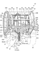
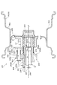
- FIG. 1 is a view of the towing state of the beach clean garbage sorting and collecting machine according to the present embodiment as viewed from the left side.
- FIG. 2 is a perspective view of the waste sorting and collecting machine as viewed from the rear.
- FIG. 3 is a view of the waste sorting and collecting machine as viewed from below.
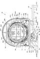
- FIG. 4 is a view of the waste sorting and collecting machine as viewed from the right side.
- FIG. 5 is a perspective view of the garbage sorting and collecting machine as seen from the left side with the wheels removed.
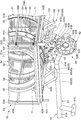
- FIG. 6 is a view of the mechanical part of the waste sorting and collecting machine as viewed from the right side along with the peripheral configuration.
- FIG. 7 is a view of the mechanism portion as viewed from the rear together with the peripheral configuration.
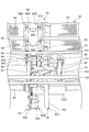
- FIG. 8 is a view of the gear switching mechanism of the waste sorting and collecting machine as viewed from the rear upper side together with the peripheral configuration.
- FIG. 9 is a view of the gear switching mechanism as viewed from below together with the peripheral configuration.
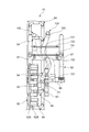
- FIG. 10 is a side sectional view showing the unlocked wheel lock mechanism together with the peripheral configuration.
- FIG. 11 is a side sectional view showing the wheel lock mechanism in operation together with the peripheral configuration.
- FIG. 12 is a side sectional view showing the wheel lock mechanism in the lock pin contact state together with the peripheral configuration.
- FIG. 13 is a side sectional view showing the wheel lock mechanism in the lock pin engagement state together with the peripheral configuration.
- 14A is a left side view of the hub portion 57, FIG.
- FIG. 14B is a cross-sectional view (XX cross-sectional view of FIG. 14A), and FIG. 14C is a right side view.
- 15A is a left side view of the slider
- FIG. 15B is a sectional view (XX sectional view of FIG. 15A).
- 16 (A) is a left side view of the snap ring
- FIG. 16 (B) is a sectional view (XX sectional view of FIG. 16 (A))
- FIG. 16 (C) is FIG. 16 (A) from the Y direction.
- FIG. 16D is a view of FIG. 16A viewed from the Z direction.
- FIG. 1 is a view of the towing state of the beach clean garbage sorting and collecting machine according to the present embodiment as viewed from the left side.
- a beach clean garbage sorting and collecting machine (hereinafter referred to as a garbage sorting and collecting machine) 50 is configured as a towable work vehicle that can be pulled by a vehicle 1.
- a vehicle (towing vehicle) 1 is a small vehicle suitable for traveling in sandy areas such as a beach, and front and rear front wheels 2 and rear wheels that are relatively large-diameter low-pressure balloon tires in front of and behind a compact and lightweight vehicle body. It is configured as a so-called ATV (All Terrain Vehicle) that is provided with a wheel 3 and has a large minimum ground clearance to improve running performance mainly on rough terrain.
- the vehicle body frame 4 of the vehicle 1 forms a box structure that is long in the front-rear direction in the center portion in the vehicle width direction, and an engine 5 as a prime mover of the vehicle 1 is mounted in a substantially central portion of the vehicle body frame 4.
- the engine 5 is, for example, a water-cooled single cylinder engine, and outputs the rotational power of the crankshaft to the front and rear propeller shafts 6a and 6b via a gear meshing type transmission.
- the rotational power output to the front and rear propeller shafts 6a and 6b is output to the left and right front wheels 2 or the rear wheel 3 via the front and rear speed reduction devices 7a and 7b, respectively.
- the vehicle 1 is a so-called semi-automatic vehicle in which the gear ratio of the transmission can be electrically changed.
- the gear ratio can be changed only by operating a change button or the like without performing clutch operation through a centrifugal clutch. Is possible.
- Such a vehicle 1 is suitable for traveling with a large traveling load and traveling at a constant speed as compared with a vehicle having a belt-type transmission.
- the vehicle 1 is not limited to a semi-automatic vehicle, and may be an automatic transmission vehicle in which a change in gear ratio is automated, for example.
- the left and right front wheels 2 are suspended from the front portion of the vehicle body frame 4 via an independent suspension type front suspension 8a, and the left and right rear wheels 3 are suspended from the rear portion of the vehicle body frame 4 via, for example, a swing arm type rear suspension 8b. Suspended. At the rear end of the swing arm 9 of the rear suspension 8b, a trailer hitch 11 for towing the waste sorting and collecting machine 50 is provided.
- reference numeral 12a indicates a front carrier supported on the front part of the vehicle body frame 4
- reference numeral 12b indicates a rear carrier supported on the rear part of the vehicle body frame 4.
- FIG. 2 is a perspective view of the waste sorting and collecting machine 50 as viewed from the rear
- FIG. 3 is a view of the waste sorting and collecting machine 50 as viewed from below
- FIG. 4 is a view of the waste sorting and collecting machine 50 as viewed from the right side
- FIG. It is the perspective view which removed the machine 50 from the wheel 53, and was seen from the left side.
- symbol C ⁇ b> 1 indicates the width center of the waste sorting and collecting machine 50
- symbol LA indicates the axis (rotation center) of the drum-type sieve body 54 that is a rotating body
- symbol LB indicates the axle 52.
- An axis (center of rotation) is shown. As shown in FIG.
- the waste sorting and collecting machine 50 includes a vehicle body frame 51 pulled by the vehicle 1, a pair of left and right wheels 53 attached to the vehicle body frame 51 via axles 52 (see FIG. 2), and a vehicle body frame. And a drum-type sieve body 54 attached to 51, which functions as a mobile sand separator that separates sand from garbage collected by a known beach cleaner.
- a joint (also referred to as a hitch coupler) 55 that can be attached to the trailer hitch 11 is provided at the front end portion of the body frame 51 of the waste sorting and collecting machine 50, and the trailer hitch 11 provided at the rear portion of the vehicle 1 via the joint 55.
- the vehicle 1 is configured to be able to tow the garbage separation and recovery machine 50.
- the vehicle body frame 51 includes a single main frame 61 that extends in the front-rear direction of the vehicle body, a sieve support frame 62 that is supported above the main frame 61, and a drum-type sieve body 54 that is supported by the sieve support frame 62. And a shield body 63 covering the periphery, which are formed symmetrically with respect to the width center C1 of the waste sorting and collecting machine 50.
- the main frame 61 includes a front portion 61A that linearly extends rearward from the joint 55 and a rear portion 61B that linearly extends rearward and downward from the rear end of the front portion 61A in a side view. As shown in FIG.
- the front part 61 ⁇ / b> A and the rear part 61 ⁇ / b> B are formed so as to linearly extend the width center C ⁇ b> 1 of the vehicle body in plan view.
- the front part 61A and the rear part 61B are integrally formed by bending a single metal pipe.
- the front part 61A is formed several times longer than the rear part 61B, and extends forward longer than the sieve support frame 62 supported above the main frame 61.
- an inverted T-shaped stand 61C extending downward is provided in the vicinity of the joint 55 of the front portion 61A.
- the stand 61C contacts the ground when the joint 55 is removed from the vehicle 1, and the main frame 61 is in contact with the ground. Is supported while floating above the ground.
- a cylindrical axle support 61D that rotatably supports the axle 52 is provided at the rear end of the rear portion 61B.
- the axle support 61D is formed of a cylindrical pipe (in this configuration, a metal pipe) extending in the vehicle width direction, and rotatably supports the axle 52 along the vehicle width direction.
- the axle support 61D is provided at the width center C1 of the vehicle body and supports the center portion of the axle 52.
- the axle 52 is an axle that rotates integrally with at least one of the left and right wheels 53.
- the axle 52 is rigidly connected to one wheel 53 so as to rotate integrally, and the other wheel 53 is locked / unlocked via a wheel lock mechanism 201 (also referred to as lock / lock free). It is connected freely.
- the sieve body support frame 62 is a frame member that supports the drum type sieve body 54 from below, and is formed symmetrically with respect to the width center C1 of the vehicle body by combining a plurality of metal pipes.
- the sieve support frame 62 is supported above the main frame 61 via a support frame 65 between the main frame 61 and the screen support frame 62.
- the support frame 65 has a front support frame 66 provided in front of the axle 52 and a rear support frame 67 provided in the rear of the axle 52, and the front support frame 66.
- Is composed of a plurality of (three in this configuration) frame members extending upward from the rear portion of the front portion 61A of the main frame 61, and the front support frame 66 allows the front portion of the sieve support frame 62 to be connected to the main frame 61. Supported.
- the rear support frame 67 is a frame that extends upward from the axle support 61D that is the rear end of the main frame 61 and supports the rear portion of the sieve support frame 62 from below, and is rearwardly upward from the center in the width direction of the axle support 61D.
- a single frame member 67A extending to the left and a substantially U-shaped branch frame member 67B branching left and right from the upper end of the frame member 67A.
- the support frames 66 and 67 are also formed of metal pipes.
- the sieve support frame 62 is supported above the left and right wheels 53 by the front and rear support frames 66 and 67.
- the vertical position of the sieve support frame 62 is a position close to the upper edges of the left and right wheels 53.
- reference numeral 68 denotes a gusset that bridges the rear portion 61B of the main frame 61 and the lower end of the rear support frame 67.
- the gusset 68 allows the main frame 61, the axle support 61D, and the rear support to be supported.
- the connection strength of the frame 67 is improved.
- the sieve body support frame 62 includes a pair of left and right front and rear extension frames 62A extending in the front-rear direction of the vehicle body, and the front and rear ends of the front and rear extension frames 62A. It is formed in a four-sided frame shape having a pair of front and rear left and right extending frames 62B extending in the left and right direction, and the upper end of the front support frame 66 is connected to the front left and right extending frame 62B. The upper end is connected to the rear left and right extending frame 62B. Cylindrical members 62C extending in the vertical direction are joined to the front and rear ends of the pair of left and right front and rear extension frames 62A.
- the four corners existing on the front and rear left and right of the sieve support frame 62 are A metallic cylindrical member 62C extending in the direction is arranged.
- a part of the shield body 63 enters the cylindrical member 62 ⁇ / b> C from above, and positions the shield body 63 on the sieve body support frame 62.
- a pair of left and right guide rollers 71 are supported on the pair of front and rear left and right extending frames 62B so as to be rotatable in the front and rear direction with the roller shafts aligned in the left and right direction of the vehicle body.
- a drum-shaped sieve body 54 having a bottomed cylindrical bowl shape is placed from above, and this drum-type sieve body 54 is connected to the axis LA of the sieve body 54. It arrange
- the front and rear guide rollers 71 are arranged so as to sandwich the lower part of the drum type sieve body 54 from the front and rear, and the front and rear guide rollers 71 regulate the front and rear movement of the drum type sieve body 54.
- the drum type sieve body 54 can be stably supported. Since the drum type sieve body 54 is merely placed on the guide roller 71, the drum type sieve body 54 can be easily attached and detached by lifting the drum type sieve body 54.
- the drum-type sieve body 54 is a large-sized part having a bottomed cylindrical bowl shape, into which sand-mixed garbage collected on the beach by a known beach cleaner is placed. The sand is dropped by the rotation of the body 54, and only dust remains in the sieve body 54.
- the drum-type sieve body 54 has a metal sieve body 81 that forms a skeleton of a bottomed cylinder whose one end side (left side in the present configuration) is open and the other end side (right side) is closed by a bottom 54A; And a metal net member 82 covering the periphery of the sieve body 81.
- the sieve body 81 includes an opening-side cylinder portion 81A that surrounds the opening-side end portion in a cylindrical shape along the circumferential direction, a closing-side cylinder portion 81B that surrounds the closing-side end portion in a cylindrical shape along the circumferential direction, and a sieve body 81.
- Intermediate cylindrical portion 81C that surrounds the axial intermediate portion in a cylindrical shape along the circumferential direction, and these cylindrical portions 81A to 81C are cylindrical metal plate members centering on the axis LA of the drum-type sieve body 54. It is formed.
- cylinder portions 81A to 81C are connected by a plurality of axial extension rods 84 formed of metal steel pipes or metal rods extending in the direction of the axis LA of the drum-type sieve body 54.
- the axial extension rods 84 are arranged in the circumferential direction. Many are provided at intervals.
- a mesh member 82 is attached from the outside of the axial extension rod 84 so as to cover the outer periphery of the sieve body 81.
- the closing side cylinder part 81B is provided with a lattice part 85 in which metal steel pipes or metal bar parts are assembled in a lattice shape so as to surround the opening of the closing side cylinder part 81B.
- a metal mesh member 86 is attached from the outside so as to cover the openings of the lattice portion 85, and the lattice portion 85 and the mesh member 86 form a bottom portion 54 ⁇ / b> A of the drum type sieve body 54.
- the three cylindrical portions (opening-side cylindrical portion 81A, intermediate cylindrical portion 81C, and closed-side cylindrical portion 81B) are arranged at intervals in the direction of the axis LA, and the space between them is covered with the net member 82, thus ensuring strength.
- the net member 82 it is possible to secure a wide net area that functions as a sieve for the drum-type sieve body 54.
- the bottom portion 54A is also formed in a lattice shape and is covered with the net member 86, the bottom portion 54A can also function as a sieve.
- the axially extending rod 84 and the lattice portion 85 are members that are located on the inner side of the mesh members 82 and 86 and project toward the inner side of the sieve main body 81, these members 84 and 85 are disposed inside the drum-type sieve body 54. It can be made to function also as a sand pulverization body which grinds the lump of sand thrown into.
- the opening side cylinder part 81 ⁇ / b> A and the closing side cylinder part 81 ⁇ / b> B also function as sliding members on which the guide roller 71 slides. That is, the opening-side cylinder portion 81A and the closing-side cylinder portion 81B have the same diameter and extend with a predetermined width in the direction of the axis LA of the drum-type sieve body 54, and the outer peripheral surface of the guide roller 71 is in contact with this width. A sliding surface of the roller 71 is configured.
- a flange portion 88 projecting outward is integrally provided on the inner side in the width direction of the opening-side cylinder portion 81A and the closing-side cylinder portion 81B, and the guide roller 71 and the drum-type sieve body 54 are formed by these flange portions 88.
- the displacement in the vehicle width direction is regulated.
- the shield body 63 is formed symmetrically with respect to the width center C ⁇ b> 1 of the vehicle body, and the left and right sides of the sieve support frame 62 are directed upward so as to cover the left and right sides of the drum type sieve body 54.
- the side shield member 63A supports the sieve body by bending the metal pipe into a U-shape and inserting both ends thereof into a pair of front and rear cylindrical members 62C located on the left and right sides of the sieve support frame 62 from above. It is connected to the frame 62. Further, the surrounding shield member 63B bridges the front portion, the upper portion, and the rear portion of the pair of left and right side shield members 63A using a metal pipe, and covers the front, upper, and rear of the drum type sieve body 54. Further, the surrounding shield member 63B also functions as a cross member that reinforces the pair of left and right side shield members 63A.
- the side shield member 63A located on the opening side (left side) of the drum-type sieve body 54 includes an inner side of the side shield member 63A.
- a door member 63D that allows the opening to be opened and closed is provided.
- the door member 63D has substantially the same shape as the side shield member 63A, and includes a metal pipe door frame that is openably and closably connected to the side shield member 63A via a hinge 63E (see FIG. 4).
- An area surrounded by the door frame is covered with a covering member such as a net member.
- the door member 63D regulates the jumping of dust from the opening side of the drum type sieve body 54 to the outside of the vehicle, and by opening the door member 63D, the sand mixed in the drum type sieve body 54 is collected.
- Garbage can be thrown in. 2 and 5
- reference numeral 63 ⁇ / b> F is a handle provided on the door member 63 ⁇ / b> D.
- Each figure shows the case where the shield body 63 is formed only by a skeleton structure. However, the entire outer periphery of the shield body 63 is covered with a covering member such as a net member, and sand from the drum type sieve body 54 is covered. You may make it the structure which suppresses scattering with the shield body 63.
- the drum type sieve body 54 is rotatably supported by the guide roller 71 in this configuration, the drum type sieve body 54 is efficiently screened by rotating the drum type sieve body 54 with dust mixed in the sand, Only dust that does not pass through the net members 82 and 84 can be left in the sieve body 54, and only garbage such as beverage containers remaining on the beach, paper waste, cigarette butts can be left, and the drum-type sieve body 54 can be easily rotated with a relatively small force.
- the garbage separation and collection machine 50 of this configuration has an automatic rotation mode in which the drum type sieve body 54 is rotated by the rotational force of the wheel 53, and a manual rotation mode in which the drum 53 is manually rotated by being separated from the rotational force of the wheel 53.
- a mechanism unit (transmission mechanism) 91 for switching is provided. For this reason, if the automatic rotation mode is set in a place where the vehicle 1 can be pulled, the garbage can be separated and collected by the traction force of the vehicle 1, and the manual rotation mode is set in the rough terrain where the vehicle 1 is difficult to pull. By setting, it is possible to easily separate and collect garbage manually.
- the mechanism portion 91 and the peripheral structure will be described.
- a metal annular handle 89 is attached to the opening end portion (left end portion) of the drum-type sieve body 54 on the outer side in the vehicle width direction from the opening end portion. It is done.
- This handle 89 is used as a gripping part for an operator to grip and easily rotate the drum-type sieve body 54 when the drum-type sieve body 54 is in a freely rotatable state (corresponding to the manual rotation mode). Is done.
- the handle 89 can be gripped from the outside by opening the door member 63D, that is, manual rotation is performed with the door member 63D open.
- FIG. 6 is a view of the mechanism portion 91 as viewed from the right side along with the peripheral configuration
- FIG. 7 is a view as seen from the rear.
- the mechanism 91 includes a drive gear 92 attached to the axle 52, a driven gear 93 attached to the vehicle body frame 51 so as to be able to engage / disengage with the drive gear 92, and a drum And a gear switching mechanism (switching) for changing the gear position by sliding the driven gear 93 at the position where the driven gear 93 meshes with the drive gear 92.
- Means 95.
- the drive gear 92 is attached so as to rotate integrally with the axle 52.
- the drive gear 92 is provided near the width center C1 of the vehicle body at a position exposed from the axle support 61D in the axle 52, and in the present configuration, is provided near the left end of the axle support 61D (see FIG. 7). More specifically, the drive gear 92 includes a metal disc portion 92A whose diameter is enlarged around the axle 52 at a position near the left end of the axle support 61D, and a disc portion 92A circumference that is the circumferential direction of the drive gear 92.
- the rod-shaped member 92B may be a metal member or an elastic member such as rubber. If formed by an elastic member, the contact force between the drive gear 92 and the driven gear 93 can be relaxed.
- the driven gear 93 is inserted into a clutch pipe 96 supported by the vehicle body frame 51 so as to be rotatable and slidable in the axial direction.
- the gear meshes with / disengages from the rod-shaped member 92B.
- the state of non-meshing with the drive gear 92 means a state in which the driven gear 93 moves to the free end side of the rod-shaped member 92B and moves from the position of the rod-shaped member 92B to a fully retracted position.
- the drive gear 92 is indicated by a two-dot chain line. As shown in FIGS.
- the clutch pipe 96 is a metal pipe extending linearly in parallel with the axle 52, and the driven gear 93 is moved to the above-mentioned two positions (engaged position and non-engaged position (or retracted position). )) And is supported by the body frame 51 via a pair of left and right support frames 97.
- the pair of left and right support frames 97 are formed of metal pipes, and their rear ends are joined by welding or the like to the rear left and right extension frames 62B constituting the rear part of the sieve body support frame 62.
- the clutch pipe 96 is supported in parallel with the axle 52 at its front end.
- the driven gear 93 has a plurality of tooth portions 93 ⁇ / b> A that mesh with the rod-like member 92 ⁇ / b> B of the drive gear 92 at intervals in the circumferential direction.
- These tooth portions 93A have a protruding shape that protrudes radially outward from the center of rotation that coincides with the axis LC of the driven gear 93, and in a side view, these tooth portions 93A are adjacent to the rod-shaped member 92B adjacent to the drive gear 92. It is formed so as to be narrower than the interval, and has a shape that allows a sufficient space between adjacent rod-shaped members 92B.
- the tooth portion 93A of the driven gear 93 is gradually widened in a side view as the base end side is radially outward, and the radially outer tip side is gradually widened as it is radially outward. It is narrow, that is, formed in a tapered shape.
- the tooth portion 93A of the driven gear 93 is tapered, the gap between the tips of the adjacent tooth portions 93A can be widened, and the rod shape of the drive gear 92 is formed between the tooth portions 93A of the driven gear 93. It becomes easy to receive the member 92B. Further, when the rod-shaped member 92B of the drive gear 92 is inserted between the tooth portions 93A of the driven gear 93, the gap gradually decreases toward the proximal end side of the tooth portion 93A. The gap with the rod-shaped member 92B can be reduced, and can be reliably engaged. According to this configuration, even if the sand is adhered to the driven gear 93 and the driving gear 92, the driven gear 93 and the driving gear 92 can be easily and reliably engaged with each other, and the sand can be easily removed. can do.
- the engagement pieces 94 are provided at equal intervals in the circumferential direction on the outer periphery of the intermediate cylindrical portion 81 ⁇ / b> C that forms the intermediate skeleton of the drum type sieve body 54 in the axial direction.
- the engaging piece 94 is a U-shaped projecting member projecting radially outward, and each of the engaging pieces 94 is a pair of left and right rods projecting radially outward from the outer periphery of the sieve body 54.
- the metal pipe is bent so as to integrally have the support portion 94A and a rod-like member (projecting end) 94B extending in the axis LA direction so as to connect the outermost ends of the pair of left and right support portions 94A.
- reference numeral 94 ⁇ / b> C is an elastic member such as rubber that is mounted so as to wind the outer periphery of the rod-shaped member 94 ⁇ / b> B.
- the contact force between the engagement piece 94 and the driven gear 93 by the elastic member 94 ⁇ / b> C. Has been relaxed.
- the rod-like members 94B of the engagement pieces 94 are positioned above the rod-like member 92B of the drive gear 92 as shown in FIG. 7, and as shown in FIG. Overlap.
- a driven gear 93 is configured to be movable back and forth along the clutch pipe 96 between the rod-shaped member 94B of the engagement piece 94 and the rod-shaped member 92B of the drive gear 92, thereby, as shown in FIG.
- the lower portion of the driven gear 93 can mesh with the rod-shaped member 92B of the drive gear 92, and the lower portion of the driven gear 93 can mesh with the rod-shaped member 94B of the engagement piece 94. In this case, as shown in FIG.
- the tooth portion 93A located at the lower end of the driven gear 93 enters between the adjacent rod-shaped members 92B of the drive gear 92, and the tooth portion 93A located at the upper end of the driven gear 93 is
- the drive gear 92 rotates between the adjacent engagement pieces 94 (bar-shaped members 94B) and the wheels 53 rotate, the drum type sieve body 54 is rotationally driven via the driven gear 93.
- the interval between the adjacent engagement pieces 94 is set to a large interval such that a plurality of tooth portions 93A of the driven gear 93 (two in this configuration) are included.
- the rotation of 93 is decelerated and transmitted to the drum-type sieve body 54, and the rotational speed of the drum-type sieve body 54 is reduced to a desired speed suitable for the sieve, and a wide space is provided between the engagement piece 94 and the driven gear 93. Since there is a gap, even if sand falling from the drum type sieve body 54 adheres to the engagement piece 94 or the driven gear 93, the rotation of the drum type sieve body 54 by the driven gear 93 is not hindered.
- the tooth portion 93A of the driven gear 93 is formed in a tapered shape, a gap can be widened between the tips of the adjacent tooth portions 93A, and the engagement piece 94 can easily enter the gap.
- the driven gear 93 and the engagement piece 94 can be easily meshed, and can be easily meshed even when sand adheres.
- the axis LA which is the rotation center of the drum-type sieve body 54, is shifted in the front-rear direction from the axle 52 (axis LB) above the axle 52 (axis LB) (in this configuration, the drum-type
- the axis LA of the sieve body 54 is disposed at a position shifted forward from the axle 52 (axis line LB), and the axis LC which is the rotation center of the driven gear 93 is the axis LA of the drum type sieve body 54 in a side view.
- the axle 52 (axis line LB) the axle 52 (axis line LB).
- the driven gear 93 can be arranged using the empty space between the drum type sieve body 54 and the axle 52, the mechanism 91 can be arranged compactly, and the drum type sieve body 54 and the driven gear 93 can be arranged. As compared with the case where the axles 52 are arranged vertically in the vertical direction, the axles 52 can be arranged more compactly in the vertical direction.
- the axis LC that is the rotation center of the driven gear 93 is located on the straight line L1 that connects the axis LA that is the rotation center of the drum type sieve body 54 and the axle 52 (axis LB).
- the drive gear 92, the driven gear 93, and the drum-type sieve body 54 are arranged on the straight line L1, and these can be efficiently arranged close to each other.
- the driven gear 93 overlaps the wheel 53 in a side view, so that the space between the wheels 53 can be used efficiently and the left and right of the driven gear 93 can be guarded by the wheel 53. .
- the rear portion 61B of the main frame 61 is located at the front lower side of the driven gear 93 and the rear support frame 97 is located at the rear lower side.
- the driven gear 93 can be guarded from below.
- the front support frame 66 is positioned in front of the driven gear 93
- the rear support frame 97 is positioned in the rear of the driven gear 93.
- the support frames 66 and 67 guard the front and rear of the driven gear 93. be able to.
- FIG. 8 is a diagram of the gear switching mechanism 95 as viewed from the rear upper side along with the peripheral configuration
- FIG. 9 is a diagram of the gear switching mechanism 95 as viewed from below.
- the gear switching mechanism 95 has an operation lever 100 that slides the driven gear 93 in the axial direction of the clutch pipe 96.
- the operation lever 100 is formed of a metal pipe that is bent in a substantially Z shape in plan view, and its tip 101 is connected to a cylindrical portion 93 ⁇ / b> C integrated with the driven gear 93, and an intermediate portion thereof.
- 102 is connected to a cross plate 111 that bridges between a pair of left and right support frames 97 that support the clutch pipe 96, and a base end portion 103 is formed in a gripping portion that is bent downward and gripped by an operator.
- the connecting portion between the distal end portion 101 of the operation lever 100 and the driven gear 93 is a universal joint, and the operation lever 100 is rotatable to the left and right with the pin P1 (see FIG. 9) of the connecting portion as a fulcrum. And it is connected so that it can swing up and down.
- the connecting portion between the intermediate portion 102 of the operating lever 100 and the cross plate 111 is also a universal joint, and the operating lever 100 can be pivoted left and right with the pin P2 (see FIG. 8) of the connecting portion as a fulcrum. And it is connected so that it can swing up and down. For this reason, as shown in FIG.
- a plate-like gate member 122 having an engagement groove 121 into which the operation lever 100 is fitted is provided at a position behind the cross plate 111 of the vehicle body frame 51.
- the engagement groove 121 of the gate member 122 is a groove shallower than the pair of left and right deep groove portions 121A and 121B extending downward with a space left and right and the pair of left and right deep groove portions 121A and 121B.
- the shallow groove portion 121C connecting the upper half portions of the deep groove portions 121A and 121B to the left and right, and of the pair of left and right deep groove portions 121A and 121B, the deep groove portion 121B on one side (right side) is a driven gear.
- the engagement groove 121 functions as a gate groove that guides the operation lever 100 to the meshing position and the non-meshing position, and the operator holding the operation lever 100 moves along the engagement groove 121.
- the operation lever 100 By moving the operation lever 100 in the left-right direction, the operation lever 100 can be moved to one of the deep groove portions 121A and 121B.
- the operation lever 100 is formed so that the base end portion 103 on the gripping portion side is heavy, and if the operator releases the hand with the operation lever 100 moved to one of the deep groove portions 121A and 121B, Due to its own weight, the operation lever 100 moves below the deep groove portions 121A and 121B.
- the operation lever 100 When the operation lever 100 is operated to the deepest part of the deep groove portions 121A and 121B, the left and right movements of the operation lever 100 are restricted, so that the operation lever 100 can be held at the meshing position or the non-meshing position. Thereby, the operation lever 100 is separated from the position of the automatic rotation mode in which the drum type sieve body 54 is rotated by the rotational force of the vehicle 1 and in the manual rotation mode in which the drum type sieve body is separated from the rotational force of the vehicle and manually rotated. It is possible to easily switch to and hold the position. Accordingly, the operation lever 100 functions as a switching lever that switches the operation mode between the automatic rotation mode and the manual rotation mode.
- FIGS. 10 to 13 are side sectional views showing the wheel lock mechanism 201 together with the peripheral configuration.
- reference numeral 56 denotes a wheel of the wheel 53.
- the wheel 56 is a cylindrical rim portion 56A to which a rubber tire is attached and a wheel disc portion (bridge portion) 56B that bridges the rim portion 56A.
- These two-piece wheels are made of a metal material such as an aluminum alloy or iron.
- a metal hub portion 57 is attached to the inner surface of the wheel disc portion 56B in the vehicle width direction by a fastening member (fastening bolt and nut in this embodiment) 58, and a bearing (ball bearing) 59 is attached to the hub portion 57.
- the axle 52 is rotatably supported via the wheel. Thereby, the wheel 56 and the axle 52 are connected so as to be relatively rotatable.
- the wheel lock mechanism 201 includes a slide shaft 201A attached to the end of the axle 52, a disc portion 202 provided integrally or separately with the hub portion 57, a slide member 20X that is movable toward the disc portion 202,
- the slide member 20X includes a snap ring 205 that moves the slide member 20X to two different preset positions (a lock position and an unlock position described later).
- the slide member 20X includes a slider 203 that is movable toward the disk portion 202. And a lock pin 204 which is provided on the slider 203 and can be engaged with the disk portion 202.
- These parts are formed of a metal material such as an aluminum alloy or iron.
- the slide shaft 201 ⁇ / b> A is a cylindrical part through which the axle 52 is inserted, and rotates integrally with the axle 52.
- a bearing 59 is provided between the slide shaft 201A and the hub portion 57, and the slide shaft 201A and the hub portion 52 are rotatably provided via the bearing 59.
- 14A to 14C show the left side, cross section (XX cross section of FIG. 14A) and right side of the hub portion 57, and FIGS. A left side surface and a cross section (XX cross section in FIG. 15A) of the slider 203 are shown.
- FIGS. 16A, 16B, 16C, and 16D show the snap ring 205, and FIGS. 16A and 16B show the left side surface and the cross section of the snap ring 205 (of FIG. 16A).
- FIGS. 16C and 16D are views of FIG. 16A viewed from the Y and Z directions.
- the hub portion 57 includes a cylindrical tube portion 57A that functions as a shaft support portion that supports the outer ring of the bearing 59 (see FIG. 10).
- a flange portion 57B (see FIG. 14C) having a cross-shaped side view that extends at an interval of 90 degrees radially outward of the cylindrical portion 57A is integrally provided.
- the hub portion 57 is fixed to the wheel 56 by a plurality of (four) fastening members 58 formed at a position of the distance R1.
- the disk portion 202 is integrally provided at the inner end in the vehicle width direction of the cylindrical portion 57A, and has a perfect circular collar shape with a diameter increasing from the outer peripheral surface of the cylindrical portion 57A and centering on the axis LA.
- the plurality of hole portions 202A are provided at the same phase as the hole portion 57C provided in the flange portion 57B, and a tool is inserted through the hole portion 202A on the disk portion 202 side, and the hole portion 57C on the flange portion 57B side. It is possible to fasten the fastening member 58 provided in the.
- a region between the hole portions 202 ⁇ / b> A in the disc portion 202 is a non-penetrating portion 202 ⁇ / b> B that does not penetrate the disc portion 202.
- the slider 203 includes a cylindrical tube portion 203A that is inserted into the slide shaft 201A, and a protruding portion 203B that protrudes radially outward from the outer peripheral surface of the tube portion 203A.
- the cylindrical portion 203A has an inner diameter that is substantially the same as the outer diameter of the slide shaft 201A (the outer diameter on the inner side in the vehicle width direction than the disk portion 202), and is inserted into the slide shaft 201A so as to be movable in the axial direction.
- a key groove K1A through which a key K1 (see FIG.
- a return spring (return urging member) 206 is inserted between the cylindrical portion 203A and the bearing 59 of the hub portion 57, and the slider 203 moves in the axial direction by the return spring 206. It is urged
- the return spring 206 is a coil spring having substantially the same diameter as the axle 52, and is passed through the axle 52 between the cylinder portion 203 ⁇ / b> A and the hub portion 57. Accordingly, the return spring can be disposed in a narrow space surrounded by the cylinder portion 203A, the hub portion 57, the axle 52, and the lock pin 204, and the lock pin 204 can be supported without providing a dedicated support member.
- reference numeral 206A denotes a spring receiving member (also referred to as a stopper) that receives one end of the return spring 206 (the opposite end of the slider 203).
- Through-holes 203 ⁇ / b> C that pass through are provided, and lock pins 204 are respectively held in the through-holes 203 ⁇ / b> C.
- a plurality (two in this configuration) of the lock pins 204 includes a shaft portion 204A that is substantially the same diameter as the through-hole 203C and is longer than the entire length of the through-hole 203C, and a collar portion that expands at the base end portion of the shaft portion 204A.
- a lock pin spring (lock urging member) 207 (see FIG. 10) is passed through the lock pin 204, and one end (end on the inner side in the vehicle width direction) of the lock pin spring 207 is placed on the end surface of the slider 203.
- the other end (the outer end in the vehicle width direction) is fixed to the shaft portion 204A of the lock pin 204 with a spring receiving member (also referred to as a stopper) 207A. It is urged toward the outside in the direction, that is, toward the disk portion 202.
- a spring receiving member also referred to as a stopper
- the lock pin spring 207 a coil spring having substantially the same diameter as the shaft portion 204A of the lock pin 204 is used, and the lock pin 204 can be supported without providing a dedicated support member.
- the snap ring 205 includes a cylindrical tube portion 205A that is passed through the slide shaft 201A, and in the axial direction of the axle 52 on the inner side in the vehicle width direction than the slider 203. It is provided so as to be movable and rotatable in the circumferential direction of the axle 52.
- the cylindrical portion 205A is connected to an abutting side cylindrical portion 205B that abuts against the slider 203 and an inner side in the vehicle width direction (opposite to the slider 203) than the abutting side cylindrical portion 205B.
- a non-contact side cylindrical portion 205C having a smaller diameter than 205B is integrally provided.
- the abutting side cylindrical portion 205B has an inner diameter larger than that of the slide shaft 201A (see FIG. 10), is rotatable without being in contact with the key K1 fixed to the slide shaft 201A, and is axially It is formed to be movable.
- a flange portion 205D that expands radially outward is integrally formed at the open end portion of the contact-side cylinder portion 205B, thereby ensuring a wide contact area with the slider 203.
- a stopper pin 208 protruding radially outward from the slide shaft 201A is fixed to the slide shaft 201A, and this stopper pin 208 is placed in either the locking groove portion M1 or the unlocking groove portion M2. It is designed to engage.
- the locking groove portion M1 and the unlocking groove portion M2 are linearly formed in the axle direction (the disk portion 202 side) from the open end surface of the non-contacting side cylindrical portion 205C.
- the locking groove M ⁇ b> 1 is a short groove that moves the snap ring 205 outward in the vehicle width direction to the locked position where the lock pin 204 passes through the hole 202 ⁇ / b> A of the disk 202.
- the unlocking groove portion M2 is formed into a long groove in the axle direction that retracts the snap ring 205 inward in the vehicle width direction until the lock pin 204 is in the unlocked position retracted from the disk portion 202. Is formed.
- the locking groove portions M1 and the unlocking groove portions M2 are alternately formed at an angular interval of 45 degrees, whereby the operator rotates the snap ring 205 by hand or using a tool by 45 degrees. Each time the operation is performed, the snap ring 205 is switched to a position corresponding to the lock position and the unlock position.
- the wheel lock mechanism 201 is assembled by assembling each member to the slide shaft 201A to form a subassembly, and finally fastening with bolts 220 through the axle 52. It is assumed that a stopper pin 208 is assembled in advance on the slide shaft 201A. More specifically, the snap ring 205, the slider 203, and the return spring 206 are inserted into the slide shaft 201A in this order, and the lock pin 204 and the lock are inserted into the slider 203 either before or after insertion. Assemble the pin spring 207.
- the bearing 59 and the hub portion 57 are assembled to the slide shaft 201A, and are fastened with bolts 220 through the axle 52 to the slide shaft 201A. Since the wheel lock mechanism 201 is thus sub-assembled and then attached to the axle 52, the assembly to the axle 52 is easy.
- the operation of the wheel lock mechanism 201 will be described with reference to FIGS.
- the stopper pin 208 comes into contact with the depth of the unlocking groove M2 by the return spring 206.
- the slider 203 and the snap ring 205 are moved to the opposite side (in the vehicle width direction) to the disk portion 202, and are held in a state of being locked in the deep portion of the unlocking groove M2.
- the lock pin 204 moves to the unlocked position retracted from the disk portion 202, the axle 52 and the wheel 53 are unlocked, and the wheel 53 is free with respect to the axle 52. It is held in a free state that rotates.
- the snap ring 205 is slid toward the disk portion 202 against the urging force of the return spring 206 until the stopper pin 208 comes out of the unlocking groove M2. Moving. Subsequently, the snap ring 205 is rotated, and the sliding operation force of the snap ring 205 is released at a position where the locking groove M1 of the snap ring 205 is in phase with the stopper pin 208, as shown in FIG. Due to the urging force of the return spring 206, the slider 203 and the snap ring 205 are pushed out to the side opposite to the disk portion 202 (inward in the vehicle width direction) until the stopper pin 208 contacts the back of the locking groove portion M1. As a result, the stopper pin 208 is held in a state of being locked in the inner part of the locking groove M1.
- the slider 203 moves to the lock position where the hole 202A of the disk portion 202 is located within the movement stroke S (see FIG. 11) along the axial direction of the lock pin 204.
- the phase of the lock pin 204 and the hole 202A of the disk portion 202 is not always in phase. If the phase is not in phase, as shown in FIG. 53 is rotated, and the lock pin 204 is held in contact with the non-penetrating portion 202B, which is a region between the hole portions 202A of the disk portion 202, by the urging force of the lock pin spring 207.
- the lock pin 204 when the lock pin 204 and the hole 202A of the disk portion 202 are out of phase, the lock pin 204 is held in a biased state so as to contact the non-penetrating portion 202B of the disk portion 202. Therefore, when the phases of the lock pin 204 and the hole 202A of the disk part 202 are matched, the lock pin 204 immediately enters the hole 202A of the disk part 202 by the urging force and is held in the locked state (FIG. 13). reference). Therefore, the axle 52 and the wheel 53 are locked, and the axle 52 and the wheel 53 are connected so as to rotate integrally.
- an axle 52 is rigidly connected to one wheel 53, and a bearing (ball bearing) is provided between the other wheel 53 and the axle 52 as shown in FIG. 59 is inserted to form a freehub structure.
- a bearing ball bearing
- the drum-type sieve body 54 having the above cannot be rotated, and the wheel 53 does not rotate and is dragged. Therefore, in the waste sorting and collecting machine 50, when the amount of sand and dust in the drum type sieve 54 is large, when wet sand and dust are carried, and when traveling in a place with little friction such as sand. As described above, the left and right wheels are switched to the locked state as described above, and the drum type sieve body 54 having a weight can be rotated by the left and right wheels 53, and the drag of the wheels 53 can be avoided. Further, in the manual rotation mode, the force required to rotate the drum type sieve body 54 can be reduced by releasing the lock state of the left and right wheels, and the rotation can be facilitated.
- the wheel lock mechanism 201 includes a disk portion 202 that rotates integrally with the wheel 53 on the inner side of the rim portion 56A of the wheel 53, and a disk on the inner side of the rim portion 56A. Since there is a slide member 20X (slider 203 and lock pin 204) that moves in the axial direction of the axle 52 so as to be engageable with the portion 202 and rotates integrally with the axle 52, the wheel is made using the space inside the rim portion 56A.
- the lock mechanism 201 can be arranged in a compact manner, and the wheel lock mechanism 201 can be prevented from being covered with sand falling from the drum-type sieve body 54 and surrounding sand by the tires attached to the rim portion 56A and the outer periphery of the rim portion 56A.
- the waste sorting and collecting machine 50 is a traction type simple vehicle that does not include a drive source (engine) and that does not include a brake device or the like in the wheel 53. There is always a dead space inside the portion 56A.
- all the parts constituting the wheel lock mechanism 201 are formed as parts having an outer diameter smaller than the inner diameter of the rim part 56A of the wheel 56, and the wheel disk part ( Since the entire wheel lock mechanism 201 is efficiently and compactly arranged, it is possible to avoid the influence of surrounding sand and the like on these wheels.
- the disk portion 202 and the lock pin 204 which are the lock portions of the wheel lock mechanism 201, and the springs 206 and 207 for operating the respective portions are within the width of the rim portion 56A.
- the disk portion 202 and the lock pin 204 are engaged within the width of the rim portion 56A, so that the influence of sand or the like on the engaging portion and the operating portion can be effectively avoided, and the wheel lock It is possible to operate the mechanism 201 smoothly. Furthermore, since the wheel lock mechanism 201 is provided on the inner side in the vehicle width direction with respect to the wheel 56 of the wheel 53, the wheel locking mechanism 201 does not protrude outward in the vehicle width direction of the waste sorting and collecting machine 50, and the wheel 53 and the axle support 61D (FIG. 2). And a large space of the waste sorting and collecting machine 50 can be avoided.
- the disk portion 202 has a hole portion 202A penetrating in the axial direction of the axle 52 and a non-penetrating non-penetrating portion 202B, and the slide member 20X is a lock pin that moves in the axial direction so as to be able to enter the hole portion 202A.
- the lock pin 204 is urged toward the disk portion 202 and is brought into contact with the non-penetrating portion 202B until the phase matches the hole 202A. Since the lock pin spring (lock urging member) 207 is provided to enter the shaft, the axle 52 and the wheel 53 can be automatically locked if the phases of the lock pin 204 and the hole 202A of the disk portion 202 are matched.
- the lock pin 204 is movably held by the slider 203, and the slider 203 positions the disk portion 202 within the movement stroke S (see FIG. 11) of the lock pin 204 and enters the hole portion 202A. Then, it moves to the unlock position where the disk portion 202 is positioned outside the hole portion 202A which is outside the movement stroke S, so that the lock / unlock can be easily switched by the movement of the slider 203.
- a return spring (return urging member) 206 that urges the slider 203 toward the unlocked position and a wheel shaft 52 are rotatably provided.
- the rotation of the slider 203 against the urging force of the return spring 206 is achieved by the rotation. Since the snap ring 205 that moves to the locked position is provided, the slider 203 can be easily moved to the unlocked position by the urging force of the return spring 206, and switching to the unlocked state can be easily performed.
- the wheel lock mechanism 201 can be operated by a simple operation such as an operator rotating the snap ring 205. Further, as shown in FIG. 10, since the snap ring 205 is exposed outside the width of the rim portion 56A of the wheel 53, the snap ring 205 can be operated without being obstructed by the rim portion 56A. Operability can be improved.
- the lock pin spring 207 is a coil spring that passes through the lock pin 204, and the return spring 206 is a coil spring that passes through the axle 52. Therefore, the lock pin spring 207 is arranged using a narrow space around the lock pin 204 and the axle 52. These can be laid out closer to the axle 52, and the wheel lock mechanism 201 can be made compact in the radial direction.
- the disk portion 202 is provided in the hub portion 57 of the wheel 56, and the fastening member 58 constituting the fastening portion that fastens the hub portion 57 to the wheel 56 and the hole portion 202A of the disk portion 202 are provided in the same phase. The operation of inserting the tool from the hole 202A of the disk portion 202 and fastening the hub portion 57 to the wheel 56 can be easily performed.
- the waste sorting and collecting machine 50 is supported by the body frame 51 and a drum-shaped sieve 54 having a bottomed cylindrical bowl shape that is rotatably attached to the body frame 51 pulled by the vehicle 1.
- the driving gear 92 attached to the axle 52 to which the left and right wheels 53 are attached, and the mechanism portion (transmission mechanism) 91 for transmitting the driving force of the driving gear 92 to the drum-type sieve body 54 are provided.
- the drum-type sieve body 54 can be switched to a manual rotation mode in which the drum-type sieve body 54 can be manually rotated.
- the drum type sieve body 54 can be rotated by the traction force of the vehicle 1 to separate the dust.
- the drum type sieve body 54 can be easily moved manually. It can be rotated manually to separate trash.
- the drum-type sieve body 54 can be rotated by the traction force while the vehicle 1 is towing, and the drum-type sieve body 54 can be manually rotated while the vehicle is stopped, so that the dust separation operation by the drum-type sieve body 54 can be continued.
- the drum type sieve body 54 is empty, the drum type sieve body 54 can be prevented from rotating unnecessarily during towing by setting the manual rotation mode.
- a mechanism 91 for rotating the drum type sieve body 54 includes a drive gear 92 provided on the axle 52, a driven gear 93 provided slidably on a clutch pipe 96 provided parallel to the axle 52, and a drum type. Since it is comprised with the engagement piece 94 provided in the outer periphery of the sieve body 54, it can be set as a simple meshing structure, the size of the mechanism part 91 can be achieved and the size of the waste sorting and collecting machine 50 can be reduced. . Therefore, the garbage separation and recovery machine 50 that has a simple structure, is mobile, can collect and separate garbage while moving on rough shores, and can perform garbage separation work according to the situation by switching modes. Can be provided.
- the engagement piece 94 protrudes radially outward from the outer periphery of the sieve body 54 with an interval in the circumferential direction of the drum-type sieve body 54, and the drive gear 92 extends in the circumferential direction of the gear 92.
- a plurality of rod-shaped members 92B extending in the axial direction of the axle 52 from the outer periphery of the gear are provided at intervals, and the driven gear 93 is divided into a rod-shaped member 94B that is a protruding end of the engagement piece 94 and a rod-shaped member 92B of the drive gear 92 Since it meshes, the driven gear 93 and the rod-shaped members 94B, 92B can be easily meshed, the meshing / non-meshing can be switched smoothly, and the meshing state can be maintained even when traveling on rough terrain such as the coast, and the rod-shaped members 94B, 94B, From 92B, the sand is easy to fall, and it is difficult for the sand to stay in the meshing portion, and wear can be suppressed.
- the drum-type sieve body 54 is disposed above the axle 52 at a position where the rotation center (axis line LA) of the drum-type sieve body 54 is shifted in the front-rear direction from the axle 52, and the rotation center (axis line) of the driven gear 93.
- LB is provided between the rotation center (axis LA) of the drum-type sieve body 54 and the axle 52 in a side view, and is driven by using an empty space between the drum-type sieve body 54 and the axle 52.
- a gear 93 can be arranged. Therefore, the mechanism 91 can be made compact, and the waste sorting and collecting machine 50 can be made compact in the vertical direction.
- the gear switching mechanism 95 is supported by the vehicle body frame 51 so as to be rotatable in the axle direction with the intermediate portion 102 as a fulcrum, and a driven gear 93 is connected to the distal end portion 101. Since the operation lever 100 is slid, the mode can be switched by moving the driven gear 93 with a simple structure using the single operation lever 100.
- the vehicle body frame 51 has a joint 55 attached to the trailer hitch 11 at the front end, and after the straight line extends rearward from the joint 55 through the width center C1 of the waste sorting machine 50, A main frame 61 that extends downward and supports the axle 52 at the rear end thereof, a sieve support frame 62 that is supported above the main frame 61 and that rotatably supports the drum-type sieve body 54 via a guide roller 71, and a sieve Since the shield body 63 is supported by the body support frame 62 and covers the periphery of the drum type sieve body 54, the main frame 61 is compact in the vehicle width direction and the vertical direction, and the workability above the main frame 61 is good.
- a drum type sieve body 54 is supported at a place via a sieve body support frame 62, and the drum type sieve body 5 is supported by a shield body 63. It can be covered. Therefore, the waste sorting and collecting machine 50 can be configured with a compact frame structure.
- the main frame 61 includes a front portion 61A that extends linearly rearward from the joint 55, and a rear portion 61B that extends rearward and downward from the rear end of the front portion 61A and supports the axle 52 at the rear end.
- the front portion 61A is longer than the rear portion 61B, and the driven gear 93 is disposed at a position overlapping the wheel 53 between the rear portion 61B and the drum-type sieve body 54 in a side view.
- the driven gear 93 can be compactly arranged using the space between the frame 61 and the drum-type sieve body 54, and the driven gear 93 can be guarded by the rear portion 61 ⁇ / b> B of the main frame 61 and the wheel 53. Further, the height of the joint 55 with respect to the axle 52 can be secured, and the change in the posture of the waste sorting and collecting machine 50 due to the difference in the height of the trailer hitch 11 of the towing vehicle 1 can be suppressed.
- the support frame 65 is provided to support the sieve support frame 62 above the main frame 61, and the support frame 65 extends upward from the front portion 61 ⁇ / b> A of the main frame 61 to support the sieve support frame 62. Therefore, the sieve body support frame 62 can be supported at a position close to the main frame 61, and the support rigidity of the drum type sieve body 54 can be ensured.
- the support frame 65 has a rear support frame 67 that extends upward from the rear end of the main frame 61 and supports the sieve body support frame 62, and the driven gear 93 is located behind the front support frame 66 and behind the rear support frame 66. Since it is disposed in front of the support frame 67, the front and rear of the driven gear 93 can be guarded by the support frames 66 and 67.
- the above-described embodiment is merely an aspect of the present invention, and can be arbitrarily modified and applied without departing from the gist of the present invention.
- the rotation center (axis line LA) of the drum type sieve body 54 is disposed at a position shifted forward from the axle 52, and the rotation center (LC) of the driven gear 93 is set to the drum type sieve body 54.
- the present invention is not limited to this, and the center of rotation (axis LA) of the drum-type sieve body 54 is shifted to a position rearward of the axle 52.
- the rotation center (LC) of the driven gear 93 may be disposed between the rotation center (axis line LA) of the drum type sieve body 54 and the axle 52. Even in this case, the dust sorting and collecting machine 50 can be made compact in the vertical direction as compared with the case where the drum type sieve body 54, the driven gear 93 and the axle 52 are arranged vertically in the vertical direction.
- the waste sorting and collecting machine 50 is manufactured using a metal material such as a metal pipe.
- the present invention is not limited to this, and it is manufactured using a rigid material other than a metal material such as a resin material. May be.
- the said embodiment demonstrated the case where this invention was applied to the waste-cleaning collection machine 50 for beach cleans shown in FIG. 1 etc., it is not restricted to this.
- the case of using a separation mechanism that separates sand and dust using the rotary drum-type sieve body 54 has been described.
- the rotational force of the axle 52 can be obtained by using a swing-type sieve body or the like.
- the garbage sorting and collecting machine 50 may be used at a place other than the beach.
- the present invention is applied to a work vehicle such as a small vehicle for special work (including a waste separation and collection machine) that is a vehicle smaller than a special work vehicle such as a tractor and has a dead space inside the rim portion of the wheel. May be.
Landscapes
- Engineering & Computer Science (AREA)
- Architecture (AREA)
- Civil Engineering (AREA)
- Structural Engineering (AREA)
- Cleaning Of Streets, Tracks, Or Beaches (AREA)
- Combined Means For Separation Of Solids (AREA)
Abstract
Description
また、トラクター等の特殊作業用車両には、左右の車輪を車軸にロック/アンロックする車輪ロック機構を備えるものがある(例えば、特許文献2参照)。
また、ビーチクリーン用ゴミ分別回収機は、砂地を走行する作業車であり、ふるい体からも砂が落ちるため、砂等の影響を受けないような構造や配置が臨まれるが、従来の車輪ロック機構は、その条件を満たしつつコンパクトにレイアウトすることができない。
この構成によれば、車輪ロック機構は、車輪のリム部の内側で前記車輪と一体に回転するディスク部材と、前記リム部の内側で前記ディスク部材と係合自在に車軸の軸方向に移動するとともに前記車軸と一体に回転するスライド部材とを有するので、作業車が有するリム部内側のデッドスペースを利用して車輪ロック機構をコンパクトに配置できるとともに、車輪ロック機構への周囲の砂の影響を回避することができる。
また、上記構成において、前記スライダー(203)を前記アンロック位置へ向けて付勢するリターン用付勢部材(206)と、前記車軸(52)に回転自在に設けられ、回転により前記リターン用付勢部材(206)の付勢力に抗して前記スライダー(203)を前記ロック位置へ移動させるスナップリング(205)とを設けるようにしてもよい。この構成によれば、リターン用付勢部材の付勢力によってアンロック状態への切り替えを容易に行うことができ、かつ、スナップリングを回転操作するといった簡易な操作で作動させることができる。
また、上記構成において、前記付勢部材(207)は、前記ロックピン(204)に通したコイルばねであり、前記リターン用付勢部材(206)は、前記車軸(52)に通したコイルばねにしてもよい。この構成によれば、各付勢部材をロックピン及び車軸周囲の狭いスペースを利用して配置できるとともに、車輪ロック機構を径方向にコンパクトにすることができる。
また、上記構成において、前記回転体(54)は、前記車軸(52)の上方で前記車体フレーム(51)に回転自在に取り付けられるドラム式ふるい体であり、前記作業車は、前記車軸(52)に取り付けられる駆動ギヤ(92)と、前記駆動ギヤ(92)の駆動力を前記ドラム式ふるい体(54)に伝達する伝達機構(91)とを有するゴミ分別回収機であるようにしてもよい。この構成によれば、車軸の上方にドラム式ふるい体を配置した構成で、このドラム式ふるい体から落ちる砂が車輪ロック機構に影響しないようにすることができる。
また、ディスク部材は、車軸の軸方向に貫通する孔部と非貫通の非貫通部とを有し、スライド部材は、前記孔部に進入可能に軸方向に移動するロックピンを有し、このロックピンを前記ディスク部材へ向けて付勢し、前記孔部と位相が合うまで前記非貫通部に当接させ、前記車輪が回転することで位相が合うと前記孔部に進入させる付勢部材を設けるようにすれば、ロック状態への切り替えを容易に行うことができる。
また、スライダーをアンロック位置へ向けて付勢するリターン用付勢部材と、車軸に回転自在に設けられ、回転により前記リターン用付勢部材の付勢力に抗して前記スライダーをロック位置へ移動させるスナップリングとを設けるようにすれば、リターン用付勢部材の付勢力によってアンロック状態への切り替えを容易に行うことができ、かつ、スナップリングを回転操作するといった簡易な操作で作動させることができる。
また、付勢部材は、前記ロックピンに通したコイルばねであり、リターン用付勢部材は、車軸に通したコイルばねにすれば、各付勢部材をロックピン及び車軸周囲の狭いスペースを利用して配置できるとともに、車輪ロック機構を径方向にコンパクトにすることができる。
また、ディスク部材は、車輪のハブ部に設けられ、前記ハブ部を前記車輪のホイールに締結する締結部を有し、前記締結部と前記ディスク部材の孔部とは、同位相で設けられるようにすれば、ディスク部材の孔部から工具を差し込んでハブ部をホイールに締結する作業を容易に行うことができる。
また、伝達機構は、前記ドラム式ふるい体を車軸の回転力で回転させる自動回転モードと、前記ドラム式ふるい体を車軸の回転力から切り離して手動回転自在にする手動回転モードとに切り替える切替手段を備えるようにすれば、機動性があり、様々な状況に合わせてゴミ分別作業ができる。
図1は、本実施形態に係るビーチクリーン用ゴミ分別回収機の牽引状態を左側方から見た図である。
この図に示すように、ビーチクリーン用ゴミ分別回収機(以下、ゴミ分別回収機と言う)50は、車両1で牽引可能な牽引型の作業車に構成されている。
車両(牽引車両)1は、ビーチ等の砂地での走行に適した小型車両であり、小型軽量に構成された車体の前後に、比較的大径の低圧バルーンタイヤである左右の前輪2及び後輪3を備え、最低地上高を大きく確保して主に不整地での走破性を高めた所謂ATV(All Terrain Vehicle)として構成される。車両1の車体フレーム4は、車幅方向中央部において前後に長いボックス構造を形成し、該車体フレーム4の略中央部には、車両1の原動機としてのエンジン5が搭載される。
ここで、車両1は前記変速機のギヤ比を電動により変更可能な所謂セミオート車両であり、例えば遠心クラッチを介することで、クラッチ操作を行わずにチェンジボタン等の操作のみで前記ギヤ比を変更可能である。このような車両1は、ベルト式の変速機を備えた車両と比べて、走行負荷が大きい走行や一定速度での走行にも好適である。
なお、車両1は、セミオート車両に限定されるものではなく、例えば、ギヤ比の変更を自動化したオートマチックトランスミッション車両でもよい。
なお、図中、符号12aは、車体フレーム4前部に支持されるフロントキャリアを示し、符号12bは、車体フレーム4後部に支持されるリアキャリアを示している。
図2は、ゴミ分別回収機50を後方から見た斜視図であり、図3は下方から見た図であり、図4は、右側方から見た図であり、図5は、ごみ分別回収機50を車輪53を外して左側方から見た斜視図である。なお、図3中、符号C1は、ゴミ分別回収機50の幅中心を示し、符号LAは、回転体であるドラム式ふるい体54の軸線(回転中心)を示し、符号LBは、車軸52の軸線(回転中心)を示している。
図1に示すように、ゴミ分別回収機50は、車両1に牽引される車体フレーム51と、車体フレーム51に車軸52(図2参照)を介して取り付けられる左右一対の車輪53と、車体フレーム51に取り付けられるドラム式ふるい体54とを備えており、公知のビーチクリーナで回収されたゴミから砂を分離する移動式の砂分離装置として機能する装置である。
ゴミ分別回収機50の車体フレーム51の前端部には、トレーラヒッチ11に取り付け可能なジョイント(ヒッチカプラとも称する)55が設けられ、このジョイント55を介して車両1の後部に設けられたトレーラヒッチ11に連結され、該車両1によりゴミ分別回収機50を牽引可能に構成される。
メインフレーム61は、図1に示すように、側面視で、ジョイント55から後方へ直線状に延出する前方部61Aと、前方部61Aの後端から後下方へ直線状に延びる後方部61Bとを有し、図3に示すように、平面視では、前方部61Aと後方部61Bとが車体の幅中心C1を直線状に延出するように形成される。この前方部61Aと後方部61Bとは、単一の金属製パイプを屈曲することによって一体に形成されている。
前方部61Aは、後方部61Bよりも数倍程度長く形成され、このメインフレーム61上方に支持されるふるい体支持枠62よりも前方に長く延在する。この前方部61Aのジョイント55近傍には、下方に延びる逆T字状のスタンド61Cが設けられ、このスタンド61Cは、ジョイント55を車両1から取り外している場合に、地面に当接してメインフレーム61を地面から浮かした状態に支持する。
この車軸52は、左右の車輪53の少なくとも一方と一体回転する車軸である。
この車軸52は、一方の車輪53に対しては一体回転するようにリジットで連結され、他方の車輪53に対しては車輪ロック機構201を介してロック/アンロック(ロック/ロックフリーとも称する)自在に連結されている。このため、ゴミ分別回収機50が車両1に牽引された場合には、車輪53の回転に合わせて車軸52が同一の回転数で回転する。
また、このゴミ分別回収機50では、他方の車輪53と車軸52との間に後述する軸受(ボールベアリング)59を追加し、フリーハブ構造にしているので、左右の車輪53をリジットに組む場合と比較して、ゴミ分別回収機50を牽く時の取り回し性を格段に向上することができる。
図4及び図5に示すように、支持フレーム65は、車軸52よりも前方に設けられる前方支持フレーム66と、車軸52よりも後方に設けられる後方支持フレーム67とを有し、前方支持フレーム66は、メインフレーム61の前方部61Aの後部から上方に延びる複数(本構成では3本)のフレーム部材で構成され、これら前方支持フレーム66により、ふるい体支持枠62の前部がメインフレーム61に支持される。
本構成では、この前後の支持フレーム66,67によって、ふるい体支持枠62を左右の車輪53よりも上方に支持している。この場合、このふるい体支持枠62の上下位置は、左右の車輪53の上縁に近接する位置とされる。これにより、ふるい体支持枠62を車輪53との干渉を避けつつ低い位置に設け、ドラム式ふるい体54を作業性に優れた低い位置に設けるようにしている。
なお、図4中、符号68は、メインフレーム61の後方部61Bと後方支持フレーム67の下端との間を架橋するガセットであり、このガセット68によって、メインフレーム61、車軸支持体61D及び後方支持フレーム67の連結強度を向上させている。
この左右一対の前後延出フレーム62Aの前後端には、上下方向に延びる筒状部材62Cが接合され、これによって、ふるい体支持枠62の前後左右に存在する4つの角部には、上下方向に延びる金属製の筒状部材62Cが配置される。この筒状部材62Cには、上方からシールド体63の一部が入り、シールド体63をふるい体支持枠62に位置決めする。
この場合、図4に示すように、前後のガイドローラー71は、ドラム式ふるい体54の下部を前後から挟むように配置され、前後のガイドローラー71によってドラム式ふるい体54の前後移動を規制し、ドラム式ふるい体54を安定して支持することができる。なお、ドラム式ふるい体54は、ガイドローラー71に載置されるだけなので、ドラム式ふるい体54を持ち上げればドラム式ふるい体54を容易に着脱可能である。
このドラム式ふるい体54は、一端側(本構成では左側)が開口し、他端側(右側)が底部54Aで閉塞される有底円筒の骨格部を形成する金属製のふるい本体81と、このふるい本体81の周囲を覆う金属製の網部材82とを備えている。
これら筒部81A~81Cは、ドラム式ふるい体54の軸線LA方向に延びる金属鋼管或いは金属棒で形成された複数の軸方向延長ロッド84で連結され、この軸方向延長ロッド84は、周方向に間隔を空けて多数設けられている。そして、この軸方向延長ロッド84の外側から、ふるい本体81の外周を覆うように網部材82が取り付けられる。
図4及び図5に示すように、閉塞側筒部81Bには、この閉塞側筒部81Bの開口を囲うように金属鋼管或いは金属棒部を格子状に組んだ格子部85が設けられ、この格子部85の開口を覆うように外側から金属製の網部材86が取り付けられ、これら格子部85及び網部材86によって、ドラム式ふるい体54の底部54Aが形成される。
また、軸方向延長ロッド84及び格子部85は、網部材82,86の内側に位置してふるい本体81の内側に突出する部材であるため、これら部材84,85を、ドラム式ふるい体54内に投入された砂の塊を粉砕する砂粉砕体としても機能させることができる。
側方シールド部材63Aは、金属パイプをU字状に曲げ、その両端部が、ふるい体支持枠62の左右に位置する前後一対の筒状部材62Cに上方から挿入されることによって、ふるい体支持枠62に連結される。
また、周囲シールド部材63Bは、金属パイプを用いて、左右一対の側方シールド部材63Aの前部間、上部間及び後部間を架橋し、ドラム式ふるい体54の前方、上方及び後方を覆う。また、この周囲シールド部材63Bは、左右一対の側方シールド部材63Aを補強するクロスメンバーとしても機能する。
このため、この扉部材63Dによって、ドラム式ふるい体54の開口側から車外へのゴミの飛び出しを規制するとともに、この扉部材63Dを開くことによって、ドラム式ふるい体54内へ回収した砂混じりのゴミを投入することができる。なお、図2及び図5中、符号63Fは、扉部材63Dに設けられる把手である。
また、各図では、シールド体63が骨格構造だけで形成される場合を示しているが、このシールド体63の外周全体を網部材等の覆い部材で覆い、ドラム式ふるい体54からの砂の飛散をシールド体63で抑制する構成にしてもよい。
また、本構成のゴミ分別回収機50は、このドラム式ふるい体54を車輪53の回転力で回転させる自動回転モードと、車輪53の回転力から切り離して手動回転自在にする手動回転モードとに切り替える機構部(伝達機構)91を具備している。このため、車両1で牽引可能な整地された場所では、自動回転モードに設定すれば、車両1の牽引力でゴミの分別回収作業ができ、車両1で牽引し難い不整地では、手動回転モードに設定することによって人力で容易にゴミの分別回収作業ができるようになっている。
以下、この機構部91及び周辺構造について説明する。
図6及び図7に示すように、機構部91は、車軸52に取り付けられる駆動ギヤ92と、車体フレーム51に取り付けられ、駆動ギヤ92と噛合/非噛合可能に設けられる従動ギヤ93と、ドラム式ふるい体54に設けられ、従動ギヤ93が駆動ギヤ92と噛合した位置で従動ギヤ93と噛合する係合片94と、従動ギヤ93を摺動させてギヤ位置を変更するギヤ切替機構(切替手段)95とを備えている。
詳述すると、この駆動ギヤ92は、車軸支持体61Dの左端近傍位置にて車軸52を中心にして拡径する金属製の円板部92Aと、駆動ギヤ92周方向である円板部92A周方向に間隔を空けて円板部92A外周から車軸52の軸方向(右側)に延びる複数の棒状部材92Bとを備える。この棒状部材92Bは、同一の真円断面で軸方向に棒状に延び、その先端が車体の幅中心C1近傍に位置する。これによって、駆動ギヤ92の重心を車体の幅中心C1に近づけることができる。
なお、棒状部材92Bは、金属部材でもよいし、ゴム等の弾性部材で形成してもよい。弾性部材で形成すれば、駆動ギヤ92と従動ギヤ93との当接力を緩和させることが可能である。
ここで、駆動ギヤ92と非噛合の状態とは、従動ギヤ93が棒状部材92Bの自由端側へ移動して、棒状部材92Bの位置から完全に待避した位置に移動した状態を言い、図7では、この場合の駆動ギヤ92を二点鎖線で示している。
図5及び図6に示すように、クラッチパイプ96は、車軸52と平行に直線状に延びる金属製のパイプであって、従動ギヤ93を上記2位置(噛合位置と非噛合位置(或いは待避位置))へ摺動可能な長さを有し、左右一対の支持フレーム97を介して車体フレーム51に支持される。
より具体的には、従動ギヤ93の歯部93Aは、側面視で、その基端側が径方向外側にいくに従って徐々に幅広となり、径方向外側の先端側が、径方向外側にいくに従って徐々に幅狭となり、つまり、先細形状に形成されている。
この構成によれば、従動ギヤ93及び駆動ギヤ92に砂が付着した状態であっても、従動ギヤ93と駆動ギヤ92とを容易かつ確実に噛合させることが可能で、かつ、砂を落としやすくすることができる。
なお、図7中、符号94Cは、棒状部材94Bの外周を巻回するように装着されるゴム等の弾性部材であり、この弾性部材94Cにより、係合片94と従動ギヤ93との当接力が緩和されるようになっている。
この場合、図6に示すように、従動ギヤ93の下端に位置する歯部93Aが、駆動ギヤ92の隣り合う棒状部材92Bの間に入り、従動ギヤ93の上端に位置する歯部93Aが、隣り合う係合片94(棒状部材94B)の間に入り、車輪53の回転で駆動ギヤ92が回転すると、従動ギヤ93を介してドラム式ふるい体54が回転駆動される。
しかも、上記したように、従動ギヤ93の歯部93Aは、先細形状に形成されているので、隣り合う歯部93Aの先端間に空く隙間を広くでき、この隙間に係合片94が入りやすく、従動ギヤ93と係合片94を噛合し易く、砂が付着しても容易に噛合させることができる。
このため、ドラム式ふるい体54と車軸52との間の空きスペースを利用して従動ギヤ93を配置することができ、機構部91をコンパクトに配置できるとともに、ドラム式ふるい体54、従動ギヤ93及び車軸52を、上下方向に垂直に並べて配置する場合に比して、上下方向にコンパクトに配置できる。
さらに、本構成のレイアウトでは、図6に示すように、従動ギヤ93の前下方にメインフレーム61の後方部61Bが位置し、後下方に後方支持フレーム97が位置するので、既存のフレーム部材を用いて従動ギヤ93を下方からガードすることができる。また、従動ギヤ93の前方には、前方支持フレーム66が位置し、従動ギヤ93の後方には、後方支持フレーム97が位置するので、これら支持フレーム66,67によって従動ギヤ93の前後をガードすることができる。
図8は、ギヤ切替機構95を周辺構成とともに後上方から見た図であり、図9は、下方から見た図である。
図8及び図9に示すように、ギヤ切替機構95は、従動ギヤ93をクラッチパイプ96の軸方向に摺動させる操作レバー100を有している。図9に示すように、操作レバー100は、平面視で、略Z形状に屈曲する金属パイプで形成され、その先端部101が、従動ギヤ93と一体の筒部93Cに連結され、その中間部102が、クラッチパイプ96を支持する左右一対の支持フレーム97間を架橋するクロスプレート111に連結され、基端部103が、下方に屈曲して作業者が把持する把持部に形成されている。
このため、図9に示すように、操作レバー100を左右に回動させれば、従動ギヤ93を、駆動ギヤ92に噛合する位置(実線で示す位置)と、噛合しない位置(非噛合位置,二点鎖線で示す位置)とに移動させることができる。
なお、図8及び図9には、従動ギヤ93を駆動ギヤ92に噛合する位置に移動した場合の従動ギヤ93及び操作レバー100を実線で示し、従動ギヤ93を非噛合位置に移動した場合の従動ギヤ93及び操作レバー100を二点鎖線で示している。
このゲート部材122の係合溝121は、図7に示すように、左右に間隔を空けて下方に延びる左右一対の深溝部121A,121Bと、左右一対の深溝部121A,121Bよりも浅い溝であって、これら深溝部121A,121Bの上半部間を左右につなぐ浅溝部121Cとを有し、左右一対の深溝部121A,121Bのうち、一方側(右側)の深溝部121Bは、従動ギヤ93を駆動ギヤ92に噛合する位置に移動したときの操作レバー100が嵌る溝に形成され、他方側(左側)の深溝部121Aは、従動ギヤ93を非噛合位置に移動したときの操作レバー100が嵌る溝に形成されている。
操作レバー100が深溝部121A,121Bの最深部に操作されると、操作レバー100の左右への移動が規制されるため、操作レバー100を、噛合位置或いは非噛合位置に保持させることができる。これにより、操作レバー100を、ドラム式ふるい体54を車両1の回転力で回転させる自動回転モードの位置と、ドラム式ふるい体を車両の回転力から切り離し、手動回転自在にする手動回転モードの位置とに容易に切り替え、かつ、その位置に保持させることができる。これにより、操作レバー100は、自動回転モードと手動回転モードとに動作モードを切り替える切替レバーとして機能する。
図10~図13は、車輪ロック機構201を周辺構成とともに示す側断面図である。なお、図中、符号56は、車輪53のホイールであり、ホイール56は、ゴム製のタイヤが取り付けられる円筒状のリム部56Aと、リム部56A間を架橋するホイールディスク部(架橋部)56Bとからなる2ピースホイールであり、アルミニウム合金或いは鉄等の金属材料で形成されている。
このホイールディスク部56Bにおける車幅方向内側の面には、金属製のハブ部57が締結部材(本実施形態では締結ボルトとナット)58によって取り付けられ、このハブ部57に軸受(ボールベアリング)59を介して車軸52が回転自在に支持される。これによって、ホイール56と車軸52とが相対回転自在に連結されている。
スライドシャフト201Aは、車軸52が挿通される筒状部品であり、車軸52と一体的に回転する。このスライドシャフト201Aとハブ部57との間には、軸受59が設けられ、この軸受59を介してスライドシャフト201Aとハブ部52とが相対回転自在に設けられている。
ここで、図14(A)~(C)は、ハブ部57の左側面、断面(図14(A)のX-X断面)及び右側面を示し、図15(A)(B)は、スライダー203の左側面及び断面(図15(A)のX-X断面)を示している。また、図16(A)(B)(C)(D)はスナップリング205を示しており、図16(A)(B)は、スナップリング205の左側面及び断面(図16(A)のX-X断面)であり、図16(C)(D)は、図16(A)をY,Z方向から見た図である。
この複数の孔部202Aは、フランジ部57Bに設けられた孔部57Cと同位相の位置に設けられており、ディスク部202側の孔部202Aから工具を差し込み、フランジ部57B側の孔部57Cに設けられる締結部材58を締結可能である。なお、ディスク部202における孔部202A間の領域は、ディスク部202を貫通しない非貫通部202Bとされている。
筒部203Aは、その内径がスライドシャフト201Aの外径(ディスク部202よりも車幅方向内側の外径)と略同径に形成され、スライドシャフト201Aに対して軸方向移動自在に挿通される。この筒部203Aの内周面には、スライドシャフト201Aに固定されたキーK1(図10参照)が通るキー溝K1Aが設けられ、スライダー203は、このキーK1によってスライドシャフト201Aの軸方向、つまり、車軸52の軸方向だけに移動するように案内される。
図10に示すように、この筒部203Aとハブ部57の軸受59との間には、リターンスプリング(リターン用付勢部材)206が介挿され、このリターンスプリング206によってスライダー203が軸方向に沿ってディスク部202と反対側に付勢されるようになっている。
このリターンスプリング206には、車軸52と略同径のコイルばねが用いられ、筒部203Aとハブ部57との間で車軸52に通される。これによって、筒部203A、ハブ部57、車軸52及びロックピン204によって囲まれる狭いスペース内にリターンスプリングを配置でき、かつ、ロックピン204を専用の支持部材を設けることなく支持することができる。なお、図中、符号206Aは、リターンスプリング206の一端(スライダー203の反対側端部)を受けるばね受け部材(ストッパとも称する)である。
このロックピン204には、ロックピンスプリング(ロック用付勢部材)207(図10参照)が通され、このロックピンスプリング207の一端(車幅方向内側の端部)が、スライダー203の端面に当接し、他端(車幅方向外側の端部)がロックピン204の軸部204Aにばね受け部材(ストッパとも称する)207Aで固定されることによって、ロックピン204がスライダー203に対して車幅方向外側、つまり、ディスク部202へ向けて付勢される。
ロックピンスプリング207は、ロックピン204の軸部204Aと略同径のコイルばねが用いられ、ロックピン204を専用の支持部材を設けることなく支持することができる。
当接側筒部205Bは、その内径がスライドシャフト201Aより大径に形成されており(図10参照)、スライドシャフト201Aに固定されたキーK1に当接することなく回転自在で、かつ、軸方向に移動可能に形成されている。この当接側筒部205Bの開放側端部には、径方向外側に拡径するつば部205Dが一体に形成され、スライダー203との当接面積を広く確保している。
図10に示すように、スライドシャフト201Aには、スライドシャフト201Aから径方向外側に突出するストッパピン208が固定され、このストッパピン208が、ロック用溝部M1及びアンロック用溝部M2のいずれかに係合するようになっている。
本構成では、45度の角度間隔でロック用溝部M1とアンロック用溝部M2とが交互に形成されており、これによって、作業者がスナップリング205を手、或いは、工具を用いて45度回転操作する毎に、スナップリング205が上記ロック位置と上記アンロック位置とに対応する位置へと切り替わるようになっている。
より具体的には、スライドシャフト201Aに対し、スナップリング205、スライダー203、リターンスプリング206をこの順で挿通し、スライダー203には、挿通前或いは挿通後のいずれかのタイミングでロックピン204及びロックピンスプリング207を組み付ける。その後、スライドシャフト201Aに軸受59及びハブ部57を組み付け、このスライドシャフト201Aに車軸52を通してボルト220で締結する。
このように車輪ロック機構201をサブアッセンブリー化した後に車軸52に取り付けるので、車軸52への組み付けが容易である。
図10に示すように、スナップリング205のアンロック用溝部M2がストッパピン208と同位相の位置にある場合には、リターンスプリング206によって、ストッパピン208がアンロック用溝部M2の奥に当接するまでスライダー203及びスナップリング205がディスク部202と反対側(車幅方向内側)に移動し、アンロック用溝部M2の奥部に係止した状態に保持される。この場合、同図10に示すように、ロックピン204がディスク部202から待避したアンロック位置に移動するので、車軸52と車輪53とがアンロック状態となり、車輪53が車軸52に対してフリー回転するフリー状態に保持される。
続いて、スナップリング205を回動させ、スナップリング205のロック用溝部M1がストッパピン208と同位相になった位置でスナップリング205のスライド操作力を開放することにより、図12に示すように、リターンスプリング206の付勢力によって、ストッパピン208がロック用溝部M1の奥に当接するまでスライダー203及びスナップリング205がディスク部202と反対側(車幅方向内側)に押し出される。これによって、ストッパピン208がロック用溝部M1の奥部に係止した状態に保持される。
このように、ロックピン204とディスク部202の孔部202Aとの位相が合っていない場合はロックピン204がディスク部202の非貫通部202Bに当接するように付勢された状態に保持されるので、ロックピン204とディスク部202の孔部202Aとの位相が合えば、その付勢力で直ちにロックピン204がディスク部202の孔部202Aに入り、その係止状態に保持される(図13参照)。従って、車軸52と車輪53とがロック状態となり、車軸52と車輪53とが一体回転するように連結される。
この構成では、左右の車輪53をリジットに組む場合と比較して、ゴミ分別回収機50を牽く時の取り回し性を格段に向上することができるメリットがあるものの、フリーハブ構造のままだと、ドラム式ふるい体54内の砂・ゴミの搬入量が多い場合、湿った砂・ゴミを搬入した場合、及び、砂地等の摩擦が少ない場所を走行する場合等に、リジッド側の車輪53だけでは重量を有するドラム式ふるい体54を回転させることができず、その車輪53が回転せず、引きずるようになってしまう。
そこで、このゴミ分別回収機50では、ドラム式ふるい体54内の砂・ゴミの搬入量が多い場合、湿った砂・ゴミを搬入した場合、及び、砂地等の摩擦が少ない場所を走行する場合等に、上記のようにして左右輪がロック状態に切り替えられ、左右の車輪53で重量を有するドラム式ふるい体54を回転させることが可能になり、車輪53の引きずりを回避できる。
また、手動回転モードの場合には、左右輪のロック状態を解除することによりドラム式ふるい体54の回転に要する力を低減でき、回転させやすくすることができる。
ここで、ゴミ分別回収機50は、当該回収機50自体が駆動源(エンジン)を備えず、かつ、車輪53内にブレーキ装置等を備えない牽引型の簡易車両であるため、車輪53のリム部56A内側にデッドスペースが必ずできる。上述したように、本構成では、このデッドスペースに車輪ロック機構201を配置するので、車輪ロック機構201の配置スペースを別途設ける必要がなく、既存のスペースを利用して車輪ロック機構201を簡易かつコンパクトに配置することが可能になる。
特に、本構成では、図10~図13に示すように、車輪ロック機構201のロック箇所であるディスク部202とロックピン204、及び、各部を作動させるスプリング206,207がリム部56Aの幅内に完全に収容されるので、ディスク部202とロックピン204とがリム部56Aの幅内で係合し、これら係合部分及び作動部分への砂等の影響を効果的に回避でき、車輪ロック機構201を円滑に作動させることが可能である。
さらに、車輪ロック機構201は、車輪53のホイール56に対して車幅方向内側に設けられるので、ゴミ分別回収機50の車幅方向外側に張り出さず、車輪53と車軸支持体61D(図2参照)との間の空きスペースを利用して配置でき、ゴミ分別回収機50の大型化も回避できる。
この場合、ロックピン204がスライダー203に移動自在に保持され、このスライダー203が、ロックピン204の移動ストロークS(図11参照)内にディスク部202を位置させて孔部202Aに進入させるロック位置と、上記移動ストロークS外である孔部202A外にディスク部202を位置させるアンロック位置とに移動するので、スライダー203の移動によりロック/アンロックを容易に切り替えることができる。
また、このスナップリング205が、図10に示すように、車輪53のリム部56Aの幅外に露出するので、リム部56Aに邪魔されることなくスナップリング205を操作でき、車輪ロック機構201の操作性を向上できる。
また、ディスク部202は、ホイール56のハブ部57に設けられ、ハブ部57をホイール56に締結する締結部を構成する締結部材58とディスク部202の孔部202Aとが同位相で設けられるので、ディスク部202の孔部202Aから工具を差し込んでハブ部57をホイール56に締結する作業を容易に行うことができる。
この構成によれば、ギヤ切替機構95によって従動ギヤ93を駆動ギヤ92と噛合する位置へ摺動させれば、車輪53の回転力でドラム式ふるい体54を回転駆動させる自動回転モードに切り替えることができ、また、ギヤ切替機構95で従動ギヤ93を駆動ギヤ92と噛合する位置から待避させれば、ドラム式ふるい体54を手動回転できる手動回転モードに切り替えることができる。
しかも、このドラム式ふるい体54を回転させる機構部91が、車軸52に設けられる駆動ギヤ92と、車軸52に平行に設けられるクラッチパイプ96に摺動自在に設けられる従動ギヤ93と、ドラム式ふるい体54の外周に設けられる係合片94とで構成されるので、簡易な噛合構造にすることができ、機構部91の小型化を図り、ゴミ分別回収機50の小型化が可能になる。従って、簡易な構造で、機動性があり、不整地である海岸を移動しながらゴミを回収し分別することができ、モード切替によって状況に応じたゴミ分別作業が可能なゴミ分別回収機50を提供することができる。
また、ギヤ切替機構95は、車体フレーム51に中間部102を支点にして車軸方向に回動自在に支持されるとともに先端部101に従動ギヤ93が連結され、車軸方向の回動により従動ギヤ93を摺動させる操作レバー100を備えるので、単一の操作レバー100を用いた簡易な構造で、従動ギヤ93を動かしてモード切替を行うことができる。
さらに、上記支持フレーム65は、メインフレーム61の後端から上方に延びてふるい体支持枠62を支持する後方支持フレーム67を有し、従動ギヤ93は、前方支持フレーム66の後方、かつ、後方支持フレーム67の前方に配置されるので、これら支持フレーム66,67によって従動ギヤ93の前後をガードすることができる。
例えば、上記実施形態では、ドラム式ふるい体54の回転中心(軸線LA)を、車軸52よりも前方にずれた位置に配置し、従動ギヤ93の回転中心(LC)を、ドラム式ふるい体54の回転中心(軸線LA)と車軸52との間に設ける場合を説明したが、これに限らず、ドラム式ふるい体54の回転中心(軸線LA)を、車軸52よりも後方にずれた位置に配置し、従動ギヤ93の回転中心(LC)を、ドラム式ふるい体54の回転中心(軸線LA)と車軸52との間に設けてもよい。この場合でも、ドラム式ふるい体54、従動ギヤ93及び車軸52を上下方向に垂直に並べて配置する場合に比して、ゴミ分別回収機50を上下方向にコンパクト化できる。
また、上記実施形態では、図1等に示すビーチクリーン用ゴミ分別回収機50に本発明を適用する場合について説明したが、これに限らない。例えば、上記実施形態では、回転式のドラム式ふるい体54を用いて砂とゴミを分別する分別機構を用いる場合を説明したが、揺動式のふるい体を用いる等して車軸52の回転力で砂とゴミを分別する他の分別機構を用いてもよい。なお、このゴミ分別回収機50をビーチ以外の場所で用いてもよいことは勿論である。また、本発明を、トラクター等の特殊作業用車両よりも小さい車両であって、車輪のリム部内側にデッドスペースを有する特殊作業用小型車両(ゴミ分別回収機も含む)等の作業車に適用してもよい。
20X スライド部材
50 ビーチクリーン用ゴミ分別回収機(作業車)
51 車体フレーム
52 車軸
53 車輪
54 ドラム式ふるい体(回転体、分別機構)
56 ホイール
56A リム部
56B ホイールディスク部(架橋部)
57 ハブ部
57C 孔部
58 締結部材(締結部)
91 機構部(伝達機構)
92 駆動ギヤ
93 従動ギヤ
94 係合片
95 ギヤ切替機構(切替手段)
96 クラッチパイプ
201 車輪ロック機構
201A スライドシャフト
202 ディスク部(ディスク部材)
203 スライダー(スライド部材)
204 ロックピン(スライド部材)
205 スナップリング
206 リターンスプリング(リターン用付勢部材)
207 ロックピンスプリング(ロック用付勢部材)
LA ドラム式ふるい体の軸線(回転中心)
Claims (9)
- 車両に牽引される車体フレーム(51)と、車体フレーム(51)に回転自在に支持される車軸(52)に取り付けられる左右の車輪(53)とを有し、前記車軸(52)の回転力により回転する回転体(54)を有する作業車において、
前記車輪(53)を前記車軸(52)にロック/アンロックする車輪ロック機構(201)を備え、
前記車輪ロック機構(201)は、前記車輪(53)のリム部(56A)の内側で前記車輪(53)と一体に回転するディスク部材(202)と、前記リム部(56A)の内側で前記ディスク部材(202)と係合自在に前記車軸(52)の軸方向に移動するとともに前記車軸(52)と一体に回転するスライド部材(20X)とを有することを特徴とする作業車。 - 前記ディスク部材(202)は、前記車軸(52)の軸方向に貫通する孔部(202A)と非貫通の非貫通部(202B)とを有し、
前記スライド部材(20X)は、前記孔部(202A)に進入可能に軸方向に移動するロックピン(204)を有し、
前記ロックピン(204)を前記ディスク部材(202)へ向けて付勢し、前記孔部(202A)と位相が合うまで前記非貫通部(202B)に当接させ、前記車輪(53)が回転することで位相が合うと前記孔部(202A)に進入させる付勢部材(207)を設けたことを特徴とする請求項1に記載の作業車。 - 前記スライド部材(20X)は、前記ロックピン(204)を前記車軸(52)の軸方向に移動自在に支持するスライダー(203)を有し、
前記スライダー(203)は、前記ロックピン(204)を前記孔部(202A)に進入させるロック位置と、前記孔部(202A)外に位置させるアンロック位置とに移動することを特徴とする請求項2に記載の作業車。 - 前記スライダー(203)を前記アンロック位置へ向けて付勢するリターン用付勢部材(206)と、
前記車軸(52)に回転自在に設けられ、回転により前記リターン用付勢部材(206)の付勢力に抗して前記スライダー(203)を前記ロック位置へ移動させるスナップリング(205)とを設けたことを特徴とする請求項3に記載の作業車。 - 前記ディスク部材(202)と前記ロックピン(204)とは、前記リム部(56A)の幅内で係合し、前記スナップリング(205)は、前記リム部(56A)の幅外に露出することを特徴とする請求項4に記載の作業車。
- 前記付勢部材(207)は、前記ロックピン(204)に通したコイルばねであり、
前記リターン用付勢部材(206)は、前記車軸(52)に通したコイルばねであることを特徴とする請求項2乃至5のいずれかに記載の作業車。 - 前記ディスク部材(202)は、前記車輪(52)のハブ部(57)に設けられ、
前記ハブ部(57)を前記車輪(52)のホイール(56)に締結する締結部(58)を有し、前記締結部(58)と前記ディスク部材(202)の孔部(202A)とは、同位相で設けられることを特徴とする請求項1乃至6のいずれかに記載の作業車。 - 前記回転体(54)は、前記車軸(52)の上方で前記車体フレーム(51)に回転自在に取り付けられるドラム式ふるい体であり、
前記作業車は、前記車軸(52)に取り付けられる駆動ギヤ(92)と、前記駆動ギヤ(92)の駆動力を前記ドラム式ふるい体(54)に伝達する伝達機構(91)とを有するゴミ分別回収機であることを特徴とする請求項1乃至7のいずれかに記載の作業車。 - 前記伝達機構(91)は、前記ドラム式ふるい体(54)を前記車軸(52)の回転力で回転させる自動回転モードと、前記ドラム式ふるい体(54)を前記車軸(52)の回転力から切り離して手動回転自在にする手動回転モードとに切り替える切替手段(95)を備えることを特徴とする請求項8に記載の作業車。
Priority Applications (4)
| Application Number | Priority Date | Filing Date | Title |
|---|---|---|---|
| PCT/JP2010/007440 WO2012085972A1 (ja) | 2010-12-22 | 2010-12-22 | 作業車 |
| US13/884,745 US9062426B2 (en) | 2010-12-22 | 2010-12-22 | Work vehicle |
| BR112013016027-6A BR112013016027B1 (pt) | 2010-12-22 | 2010-12-22 | Veículo de trabalho. |
| JP2012549482A JP5315464B2 (ja) | 2010-12-22 | 2010-12-22 | 作業車 |
Applications Claiming Priority (1)
| Application Number | Priority Date | Filing Date | Title |
|---|---|---|---|
| PCT/JP2010/007440 WO2012085972A1 (ja) | 2010-12-22 | 2010-12-22 | 作業車 |
Publications (1)
| Publication Number | Publication Date |
|---|---|
| WO2012085972A1 true WO2012085972A1 (ja) | 2012-06-28 |
Family
ID=46313278
Family Applications (1)
| Application Number | Title | Priority Date | Filing Date |
|---|---|---|---|
| PCT/JP2010/007440 Ceased WO2012085972A1 (ja) | 2010-12-22 | 2010-12-22 | 作業車 |
Country Status (4)
| Country | Link |
|---|---|
| US (1) | US9062426B2 (ja) |
| JP (1) | JP5315464B2 (ja) |
| BR (1) | BR112013016027B1 (ja) |
| WO (1) | WO2012085972A1 (ja) |
Families Citing this family (2)
| Publication number | Priority date | Publication date | Assignee | Title |
|---|---|---|---|---|
| US8109551B2 (en) * | 2009-02-04 | 2012-02-07 | New Flyer Industries Canada Ulc | Bus cabin structure |
| WO2011158312A1 (ja) * | 2010-06-17 | 2011-12-22 | 本田技研工業株式会社 | ビーチクリーン用ゴミ分別回収機 |
Citations (4)
| Publication number | Priority date | Publication date | Assignee | Title |
|---|---|---|---|---|
| JPH02208154A (ja) * | 1989-02-07 | 1990-08-17 | Ramu Assoc:Kk | 車両用サイドブレーキ |
| JPH06156215A (ja) * | 1992-04-15 | 1994-06-03 | Soretsukusu Kk | トレーラーなどの車両用補助ブレーキ |
| JP2002225794A (ja) * | 2001-02-02 | 2002-08-14 | Yamaha Motor Co Ltd | 牽引型小型船舶 |
| JP2010174518A (ja) * | 2009-01-29 | 2010-08-12 | Honda Motor Co Ltd | ビーチクリーナ用トレーラ |
Family Cites Families (7)
| Publication number | Priority date | Publication date | Assignee | Title |
|---|---|---|---|---|
| US4014390A (en) * | 1974-02-13 | 1977-03-29 | Teixeira Antone S | Beach cleaner apparatus |
| US4241792A (en) * | 1979-01-15 | 1980-12-30 | Kratzer Donald K | Tractor drawn ground sweeper |
| US4282932A (en) * | 1979-11-01 | 1981-08-11 | Anderson Raymond R | Rock picker |
| US4542550A (en) * | 1983-02-08 | 1985-09-24 | Versatech Products Inc. | Apparatus for cleaning beaches |
| DE9305445U1 (de) * | 1993-04-10 | 1993-06-17 | Doppstadt, Werner, 42555 Velbert | Fahrbare Maschine |
| JP2006029418A (ja) | 2004-07-14 | 2006-02-02 | Yanmar Co Ltd | 走行作業機における動力伝達装置 |
| JP6143339B2 (ja) * | 2013-05-24 | 2017-06-07 | 本田技研工業株式会社 | 回転ドラム式ごみ分離機 |
-
2010
- 2010-12-22 WO PCT/JP2010/007440 patent/WO2012085972A1/ja not_active Ceased
- 2010-12-22 US US13/884,745 patent/US9062426B2/en active Active
- 2010-12-22 JP JP2012549482A patent/JP5315464B2/ja not_active Expired - Fee Related
- 2010-12-22 BR BR112013016027-6A patent/BR112013016027B1/pt not_active IP Right Cessation
Patent Citations (4)
| Publication number | Priority date | Publication date | Assignee | Title |
|---|---|---|---|---|
| JPH02208154A (ja) * | 1989-02-07 | 1990-08-17 | Ramu Assoc:Kk | 車両用サイドブレーキ |
| JPH06156215A (ja) * | 1992-04-15 | 1994-06-03 | Soretsukusu Kk | トレーラーなどの車両用補助ブレーキ |
| JP2002225794A (ja) * | 2001-02-02 | 2002-08-14 | Yamaha Motor Co Ltd | 牽引型小型船舶 |
| JP2010174518A (ja) * | 2009-01-29 | 2010-08-12 | Honda Motor Co Ltd | ビーチクリーナ用トレーラ |
Also Published As
| Publication number | Publication date |
|---|---|
| BR112013016027B1 (pt) | 2019-07-30 |
| JPWO2012085972A1 (ja) | 2014-05-22 |
| US9062426B2 (en) | 2015-06-23 |
| US20130220896A1 (en) | 2013-08-29 |
| JP5315464B2 (ja) | 2013-10-16 |
| BR112013016027A2 (pt) | 2018-06-05 |
Similar Documents
| Publication | Publication Date | Title |
|---|---|---|
| WO2011158312A1 (ja) | ビーチクリーン用ゴミ分別回収機 | |
| JP5315464B2 (ja) | 作業車 | |
| CN103015816A (zh) | 机动车门锁 | |
| JPH01175526A (ja) | 自走式作業車のトランスミツシヨン | |
| WO2014199663A1 (ja) | 作業機用の伝動装置及び作業機 | |
| WO2014069472A1 (ja) | 変速操作機構及び作業車両 | |
| JP6033565B2 (ja) | ビーチクリーナ用ドラム式ごみ分離機 | |
| JP5271452B2 (ja) | ビーチクリーン用ゴミ分別回収機 | |
| CA2719506A1 (en) | Differential gear for a vehicle | |
| JP7296453B2 (ja) | 時限的に差動可能なファイナルドライブギア装置 | |
| CN201209242Y (zh) | 垃圾清扫车的前扫帚传动离合装置 | |
| JP6932675B2 (ja) | 転圧機械 | |
| CN101298762B (zh) | 垃圾清扫车的前扫帚传动离合装置 | |
| JP4100977B2 (ja) | 乗用型作業車 | |
| US12427806B2 (en) | Axle for an off-highway vehicle (“OHV”) | |
| JP4892423B2 (ja) | クローラ式走行装置 | |
| JP6242266B2 (ja) | 作業車 | |
| JP5869356B2 (ja) | 作業車両 | |
| KR20220067889A (ko) | 산업용 차량 | |
| JPS62196461A (ja) | 除雪機等作業機の変速装置 | |
| JPS5921943Y2 (ja) | 小型自走作業機の変速装置 | |
| JPS62196456A (ja) | 除雪機等作業機の変速装置 | |
| JP2004267055A (ja) | 農作業機 | |
| CA1166560A (en) | Retractable wheel grips | |
| JPS6142789Y2 (ja) |
Legal Events
| Date | Code | Title | Description |
|---|---|---|---|
| 121 | Ep: the epo has been informed by wipo that ep was designated in this application |
Ref document number: 10860930 Country of ref document: EP Kind code of ref document: A1 |
|
| ENP | Entry into the national phase |
Ref document number: 2012549482 Country of ref document: JP Kind code of ref document: A |
|
| WWE | Wipo information: entry into national phase |
Ref document number: 13884745 Country of ref document: US |
|
| NENP | Non-entry into the national phase |
Ref country code: DE |
|
| 122 | Ep: pct application non-entry in european phase |
Ref document number: 10860930 Country of ref document: EP Kind code of ref document: A1 |
|
| REG | Reference to national code |
Ref country code: BR Ref legal event code: B01A Ref document number: 112013016027 Country of ref document: BR |
|
| ENP | Entry into the national phase |
Ref document number: 112013016027 Country of ref document: BR Kind code of ref document: A2 Effective date: 20130621 |