WO2012081945A2 - Récipient de culture de plantes pour écologisation tridimensionnelle et système d'écologisation tridimensionnelle l'utilisant - Google Patents
Récipient de culture de plantes pour écologisation tridimensionnelle et système d'écologisation tridimensionnelle l'utilisant Download PDFInfo
- Publication number
- WO2012081945A2 WO2012081945A2 PCT/KR2011/009754 KR2011009754W WO2012081945A2 WO 2012081945 A2 WO2012081945 A2 WO 2012081945A2 KR 2011009754 W KR2011009754 W KR 2011009754W WO 2012081945 A2 WO2012081945 A2 WO 2012081945A2
- Authority
- WO
- WIPO (PCT)
- Prior art keywords
- plant cultivation
- container
- stereoscopic
- water supply
- drain
- Prior art date
Links
Images


Classifications
-
- A—HUMAN NECESSITIES
- A01—AGRICULTURE; FORESTRY; ANIMAL HUSBANDRY; HUNTING; TRAPPING; FISHING
- A01G—HORTICULTURE; CULTIVATION OF VEGETABLES, FLOWERS, RICE, FRUIT, VINES, HOPS OR SEAWEED; FORESTRY; WATERING
- A01G9/00—Cultivation in receptacles, forcing-frames or greenhouses; Edging for beds, lawn or the like
- A01G9/02—Receptacles, e.g. flower-pots or boxes; Glasses for cultivating flowers
- A01G9/022—Pots for vertical horticulture
- A01G9/025—Containers and elements for greening walls
-
- Y—GENERAL TAGGING OF NEW TECHNOLOGICAL DEVELOPMENTS; GENERAL TAGGING OF CROSS-SECTIONAL TECHNOLOGIES SPANNING OVER SEVERAL SECTIONS OF THE IPC; TECHNICAL SUBJECTS COVERED BY FORMER USPC CROSS-REFERENCE ART COLLECTIONS [XRACs] AND DIGESTS
- Y02—TECHNOLOGIES OR APPLICATIONS FOR MITIGATION OR ADAPTATION AGAINST CLIMATE CHANGE
- Y02P—CLIMATE CHANGE MITIGATION TECHNOLOGIES IN THE PRODUCTION OR PROCESSING OF GOODS
- Y02P60/00—Technologies relating to agriculture, livestock or agroalimentary industries
- Y02P60/20—Reduction of greenhouse gas [GHG] emissions in agriculture, e.g. CO2
Definitions
- the present invention relates to stereoscopic recording technology. Specifically, the present invention relates to a three-dimensional green plant cultivation container and a three-dimensional green plant cultivation system using the same.
- the former patent No. 0332158 discloses a stacked plant cultivator 11, as shown in Figs.
- a spacing holder 12 for maintaining the spacing of the plant cultivation period;
- Rotating base 13 for rotating the multi-layer plant cultivator;
- a pipe 14 having a supply hose 15 for supplying the nutrient solution to the top plant cultivator;
- a water supply unit 16 installed at an upper end of the pipe 14 to eject the nutrient solution;
- the diffusion pad 17 and the circulation pump 19 are installed at the pipe 14 position below the spacing holder 12 so that the nutrient liquid ejected from the water fountain 16 is sprayed to the plant cultivator 11.
- the nutrient solution is pumped through the supply hose 15 of the pipe 14 by the operation of the circulation pump 19, and is discharged through the water fountain 16.
- the ejected nutrient solution flows into the gap holding region 12 and flows, and the nutrient solution flows to the lower plant cultivator 11 through the diffusion pad 17, and the nutrient solution flowing out to the lower part of the plant cultivator is located in the lower layer again. Flows into the gap retaining zone 12 and is stored. This operation is repeated so that the nutrient solution is sprayed to the lowest plant cultivator.
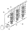
- the latter patent No. 0500019 technology is, as shown in Figure 3, formed upright in a multi-layer, plant cultivator 31 arranged in a number of rows; A spacing holder 32 for maintaining a spacing between the plant cultivators 31; Rotating base 33 for rotating the multi-layer plant cultivator; A vertical pipe 34 installed between the plurality of planters 31 arranged in a row, and having a plurality of branch pipes formed therein; A water supply pipe 35 for supplying water to the vertical pipe 34; Nozzles 36 connected to branch pipes of the vertical pipes 34 and for supplying water to individual plant cultivators 31; The water discharged through the upper and lower water circulation pipes (37, 38) and the lower water circulation pipe (38) for collecting water discharged to the lower part of the plant cultivator (31) to be introduced into the external water tank again It includes a circulation pump (39).
- the nutrient solution discharged from the plant cultivator 31 is collected in the lower water circulation pipe 38, and is supplied to the water supply pipe again from the circulation pump 39.
- These structures can be cultivated vertically by cultivating a growing plant to increase the cultivation area and to cultivate crops efficiently, and when used for horticulture, various kinds of flowers can be grown and plant cultivators in the form of columns. Because it is deployed, it provides the advantage that it can be used for ornamental purposes.
- the structure is provided with a separate means for supplying the nutrient solution, and separately installed a cold and hot water supply device capable of supplying water in response to the temperature change according to the season, it is possible to produce year-round regardless of high-temperature obstacles and cold seas, exchange soil And seedlings are provided.
- the stacked plant cultivator of the above structure has a simple structure in which the plant cultivator is stacked up, and although the water supply and circulation pipe for irrigation are provided, the structure cannot be arranged in various forms. Since there is no suitable irrigation system, there is a problem that it is not suitable as a landscaping facility for the purpose of improving the aesthetics of the city buildings or for the ornamental use.
- the growing soil in the plant cultivation vessel located at the bottom absorbs the water excessively, so that the plant of the plant cultivation vessel located at the bottom may cause severe obstacles.
- the plants planted in the plant cultivation vessel of the upper layer is contaminated by growing soil pollution or pests
- the plants of the lower layer are naturally contaminated by water discharged to the plant cultivation vessel of the lower layer after irrigation.
- the three-dimensional plant cultivation method has a problem that can be easily damaged due to all the irrigation facilities exposed to the outside.
- the present invention has been proposed in order to solve the above problems, the present invention is equipped with an independent water supply and drainage in each of the three-dimensional planting containers for cultivating each other interfering viruses between plants planted in each plant growing container It is an object of the present invention to provide a stereoscopic recording system capable of preventing infection.
- the present invention provides a water supply function and a drainage function to the plant cultivation container as an independent individual, and the water cultivation and drainage classification by allowing each plant cultivation container to be connected to each other organically up, down, left and right It is another purpose of the user to arrange the plant cultivation container in various forms as needed to create a variety of artistically landscaped three-dimensional green sculptures for the landscape landscape of the city.
- another object of the present invention is to provide a plant cultivation system capable of freshly cultivating a plant and promoting smooth growth by supplying an appropriate amount of nutrient solution at an appropriate time according to the characteristics of the plant.
- the present invention body
- a drain pipe of the body provided inside the body
- a drain provided on a bottom surface of the body and not closed by a drain pipe of the body;
- Each unit of the plant cultivation container provides a planting container for stereoscopic greening, characterized in that the water supply and drainage independently.
- the present invention also provides a frame in which two or more of the three-dimensional green plant cultivation container is fixed.
- the present invention is two or more plant cultivation containers for three-dimensional greening; And it provides a stereoscopic greening system comprising a frame fixed to the two or more stereoscopic planting containers for planting.
- a plant cultivation container provided with a water supply and drainage system is constituted by each individual individual, and the plant cultivation container is arranged in various forms in the upper, lower, left, and right directions, and as a three-dimensional green sculpture in the city. It is possible to install. For example, tower-type three-dimensional green sculptures that can be installed in front of parks, rotarys, squares, and entrances to buildings, wall-mounted green sculptures that can be installed on walls outside buildings, and large lobby rooms such as hotels and department stores.
- Interior wall surface stereoscopic green sculptures that can be installed on walls, Fence-type stereo green sculptures that are used for boundary fences such as school fences or factory fences, and retaining walls stereoscopic green sculptures that are installed on stone retaining walls or concrete retaining walls, viaducts or bridges It can be applied to various ranges such as stereoscopic green sculptures for hanging rails installed on railings and stereoscopic green sculptures for replacing soundproof walls between roads and apartments.
- urban heat island phenomena are improved by improving urban aesthetics, absorbing air pollutants such as carbon dioxide and sulfur dioxide, mitigating air pollution by supplying oxygen through green plants, and restoring urban ecosystems by creating biological habitats and green spaces in urban areas. It can exhibit mitigating and controlling earth humidity.
- the stereoscopic greening system according to the present invention includes a drop button or a timer
- an appropriate amount of water or nutrient solution water containing nutrients
- water or nutrient solution water containing nutrients
- FIG. 1 and 2 is a cross-sectional view showing an example of a stacked plant cultivation apparatus according to the prior art.
- Figure 3 is a perspective view showing another example of the stacked plant cultivation apparatus according to the prior art.
- FIG. 4 is an exploded perspective view showing the configuration of a plant cultivation container for three-dimensional greening in the first embodiment according to the present invention.
- FIG. 5 is an assembled perspective view of FIG. 4.
- FIG. 6 is a perspective view of a plant cultivation container for three-dimensional greening, except for the upper cover, in the assembled perspective view of FIG. 5.
- Figure 7 is a side cross-sectional view showing a coupling configuration of the three-dimensional planting container for planting in the first embodiment according to the present invention.
- FIG. 8 is an exploded perspective view showing the configuration of a plant cultivation container for three-dimensional greening which is a second embodiment according to the present invention.
- FIG. 9 is an assembled perspective view of FIG. 8.
- FIG. 10 is a side view of FIG. 9.
- FIG. 11 is a side cross-sectional view showing a coupling configuration of a plant cultivation container for stereoscopic greening in the second embodiment according to the present invention.
- FIG. 12 is an exploded perspective view showing the configuration of a plant cultivation container for three-dimensional greening in the third embodiment according to the present invention.
- FIG. 13 is an assembled perspective view of FIG. 12.
- FIG. 14 is a side view of FIG. 13.
- Figure 15 is a side cross-sectional view showing a coupling configuration of the three-dimensional planting container for planting in the third embodiment according to the present invention.
- FIG. 16 is a perspective view of a wall stereoscopic greening system as a first exemplary embodiment in which a plant cultivation container for stereoscopic greening, which is the first exemplary embodiment according to the present invention, is installed.
- FIG. 17 is a perspective view of a wall stereoscopic greening system as a first exemplary embodiment in which a plant cultivation container for stereoscopic greening, which is a second exemplary embodiment according to the present invention, is installed.
- FIG. 18 is a side view of FIG. 17.
- Fig. 19 is a perspective view of a wall stereoscopic greening system as a first exemplary embodiment in which a plant cultivation container for stereoscopic greening in a third exemplary embodiment according to the present invention is installed.
- FIG. 20 is a side view of FIG. 19.
- FIG. 21 is a perspective view of a Higgs boson stereoscopic recording system as a fourth embodiment according to the present invention and a perspective view of a state in which a plant cultivation container for stereoscopic recording is installed using the same.
- FIG. 22 is an exploded perspective view of a tower stereoscopic greening system in which a plant stereoscopic planting container for stereoscopic greening in the first exemplary embodiment is installed using the same as the fifth exemplary embodiment according to the present invention.
- FIG. 23 is a water supply flowchart of FIG. 22.
- FIG. 24 shows the configuration of a three-dimensional recording system for a street lamp or park lamp hanger as a sixth embodiment of the present invention.
- 25 is a perspective view of a columnar stereoscopic greening system as a seventh exemplary embodiment of the present invention, and a perspective view of a plant cultivation container for stereoscopic greening in a first exemplary embodiment using the same.
- the present invention body
- a drain pipe of the body provided inside the body
- a drain provided on a bottom surface of the body and not closed by a drain pipe of the body;
- Each unit of the plant cultivation container provides a planting container for stereoscopic greening, characterized in that the water supply and drainage independently.
- the soil receiving portion may be a cylindrical shape of a polygon whose horizontal cross-sectional shape with respect to the bottom surface is one of a circle or a triangle, a square, a pentagon, a hexagon, a hexagon, and an octagon, and specifically, the horizontal cross-sectional shape with respect to the ground surface is a square or a rectangle. It may have a cylindrical shape of phosphorus.
- the soil receiving portion is inserted into the groove formed by combining the body and the cover to be described later is accommodated in the plant cultivation container.
- the horizontal cross-sectional shape of the bottom surface of the soil receiving portion is rectangular, there is an advantage that the capacity of the soil accommodated in the soil receiving portion is much.
- the horizontal cross-sectional shape of the bottom surface of the soil receiving portion is rectangular, the capacity of the soil accommodated in the soil receiving portion is more advantageous than the cylindrical soil receiving portion.
- the water supply line and the drainage line are separately provided as the independent plant cultivation container for three-dimensional greening, it is possible to prevent contamination of the growing soil and viral infection between cultivated plants due to plant pests.
- the drain port serves to drain the liquid drained from the drain pipe of the body and the liquid drained from the soil receiving portion.
- the drain port has a structure that is not blocked by the drain pipe of the body.
- the drain pipe and the drain of the body do not necessarily have to be connected.
- the liquid drained from the drain pipe and the drain of the plant cultivation vessel located on the upper side may pass through the drain pipe and the drain of the plant cultivation vessel located on the lower side.
- the shape and location are not particularly limited as long as the liquid passing through the drain pipe does not flow into the soil container.
- the drain pipe of the body may be connected to the inner side of the body and may not contact the bottom surface of the body. In this case, it is not connected to the drain provided on the bottom of the body. At this time, by adjusting the center of the drain pipe of the body and the center of the drain so that the drainage passing through the drain pipe of the body can be introduced into the drain.
- a portion of one end of the drain pipe of the body is connected to the drain port so that the hole 59 or between the bottom of the body and the drain pipe of the body 62a) may be formed. That is, a part of one end of the drain pipe of the body is connected to the drain port, a hole 59 or 62a may be provided on the side of the drain pipe of the body. In this case, through the hole located on the side of the drain pipe of the body, the liquid flowing from the soil receiving portion can be discharged to the drain.
- the drain port is located below the drain pipe of the plant cultivation vessel located on the upper side and the liquid drained from the drain port does not flow in the other direction. It is preferable to have a structure projecting downward so that it can be introduced into the drain pipe of the plant cultivation vessel.
- the drain port may be further provided with a drain connection pipe so that the connection with the drain pipe of the plant cultivation vessel located in the lower side more easily, the drain connection pipe may be provided to be detachable to the drain. .
- drain connection lake may be coupled to a drain or drain connection pipe, and may be specifically fitted fitting.
- the coupling method may be a method known to those skilled in the art, but is not limited thereto.
- the soil receiving portion is preferably formed on the inclined surface so that even when the plant cultivation vessel is disposed two or more vertically, the opening is accommodated and exposed to the plant can be observed from the outside. It is preferable that the inclined surface forms an angle of more than 0 degrees and less than 90 degrees, preferably 15 degrees or more and 75 degrees or less with respect to the lower surface of the plant cultivation container.
- the soil receiving portion may be provided so that the opening is positioned on the inclined surface as described above by one edge of the opposite side of the opening supported by the drain pipe of the body.
- At least one water supply or drainage hole of the soil container may be provided at a wall surrounding the opening.
- the water supply or drainage hole may include a plurality of holes provided in the bottom surface direction of the soil container from the opening. That is, the water supply or drainage hole of the soil receiving portion may include a plurality of holes provided in the bottom surface direction of the soil receiving portion from the opening.
- At least one water supply hole may be provided at an upper side of the wall surrounding the opening so that liquid supplied from the upper side may flow.
- at least one drain hole may be provided at a lower side of the wall surrounding the opening to allow the water to be drained.
- the soil receiving portion may be provided with at least one protrusion on the wall surrounding the opening to allow the liquid supplied from the upper side to stay without flowing down the wall due to the inclination.
- the protrusion is installed around the water supply hole to help the liquid supplied from the upper side to flow into the soil receiving portion through the water supply hole.
- the plant cultivation container may include a fixing plate provided to cover a part of the opening of the soil receiving portion.
- the fixing plate may cover an opening closer to the bottom surface of the plant cultivation container among the openings of the soil receiving portion.
- the plant cultivation container may be provided with a protrusion for supporting the soil receiving portion on the inner lower surface of the body. This may support the bottom surface of the soil container in which the protrusion is inclined when the soil container itself is formed on an inclined surface with respect to the bottom surface of the plant cultivation container.
- a drain plate may be further provided between the soil container and the drain port.
- the drain plate is preferably provided with at least one, preferably a plurality of drain holes.
- the drain plate may prevent the drain port from being blocked by soil, plants, or other foreign matter that may flow out of the soil receiving portion, and may reduce the degree of contamination of the drained liquid.
- the water supply system of one embodiment of the plant cultivation container may be independently supplied with water through the water supply hole of each soil receiving portion.
- the plant cultivation container, the drain pipe of the cover provided to be drainable to the drain pipe of the body; And a cover having a water supply port capable of supplying water to the soil receiving portion. Even when the cover is provided, the cover is provided so as not to cover the opening for receiving or removing the plant or soil of the soil receiving portion.
- the water supply port provided in the cover is preferably formed in the groove provided in the cover so that the liquid to be supplied flows easily through the water supply port to the soil receiving portion.
- the groove has a hemispherical shape, and the water supply port is preferably provided at the center of the groove.
- the drain pipe of the cover When the cover is assembled with the container body, the drain pipe of the cover does not necessarily have to be physically fastened with the drain pipe of the body, but liquid drained from the drain pipe of the cover does not flow in the other direction and the body
- the height of the lower end of the drain pipe of the cover is preferably lower than the height of the upper end of the drain pipe of the body so as to flow into the drain pipe of the body.
- the cover is preferably provided with at least two, preferably at least four clasps in contact with the container body to be fixed to the container body.
- the cover of the planting container for stereoscopic greening may further include a branch pipe grip groove for water supply.
- the water supply branch pipe for individually supplying water to each three-dimensional planting container can be fixed.
- the water supply system of another embodiment of the plant cultivation container may include a water supply means for supplying water through the opening of the soil receiving portion, without forming a water supply hole in the soil receiving portion.
- the water supply means includes a drop spike having a hollow in the longitudinal direction inside, one end of the water supply means may be inserted into the soil receiving portion. That is, it can be used directly plugged into the soil contained in the soil receiving unit.
- each plant cultivation vessel can be supplied with water or nutrient solution directly through a water supply means plugged into the soil receptacle.
- the water supply means in which the hollow is formed in the longitudinal direction is not particularly limited as long as the hollow is formed therein so that water or nutrient solution can flow and can be inserted into the soil. Specifically, it may be a drop spike.
- the water supply means in which the hollow is formed in the longitudinal direction may include a drop button connected to the water supply pipe, a water supply lake connected to the drop button, and a water supply passage water to supply water to the individual plant cultivation vessel from the water supply pipe.
- each plant cultivation vessel may be drained from the soil receiving portion through the drain.
- the drain pipe of the body is connected to the inner surface of the body, if away from the bottom of the body, the drainage discharged from the soil receiving portion may be discharged directly to the drain of the body.
- the drainage discharged from the soil receiving portion is formed in the side of the drain pipe of the body It can pass through and be discharged to the drain.
- the installation method of one embodiment of the plurality of plant cultivation containers can be installed vertically.
- the drainage liquid introduced into the drain port is moved to the drain pipe of the plant cultivation vessel located below.
- the soil receiving portion may include a drain line connecting groove directed toward the inside of the soil receiving portion from the edge of the lower surface so that the drain, drain connection pipe or drainage connection lake of the upper plant cultivation vessel extends to the drain pipe of the lower plant cultivation vessel.
- the installation method of another embodiment of the plurality of plant cultivation vessel can be installed horizontally.
- the plurality of plant cultivation vessels When the plurality of plant cultivation vessels are arranged horizontally, it may be provided with a separate drain line for receiving the drainage from the drain, drain connection pipe or drain connection lake of the plant cultivation container. The drainage flowed into the drainage line moves to the drainage storage tank for storing the drainage.
- the said three-dimensional green-vegetation plant container is provided with the clip for fixing to the frame mentioned later.
- the clip is preferably provided on the bottom surface of the three-dimensional green plant cultivation container, it may be provided with at least one side of the container.
- the clip may be detachably provided to the plant cultivation container.
- the clip may be fixed to the container by bolts and screws, or may be secured to the container by physical fastening structures.
- the present invention also provides a frame capable of fixing at least two or more plant growing containers for stereoscopic greening.
- a frame capable of fixing at least two or more plant growing containers for stereoscopic greening.
- by using the above frame can be configured by connecting the plant cultivation container of the independent entity in combination up, down, left, right.
- the structure of the frame can be configured in various shapes, it is possible to provide a three-dimensional recording system that can be installed as an artistic three-dimensional recording sculpture of various shapes according to the shape of the frame.
- the frame preferably includes a support portion and a fixing portion having a network structure supported by the support portion and capable of fixing the plant cultivation container.
- the network structure is not particularly limited as long as it can fix the plant cultivation container, it may be a lattice structure.
- the frame may be manufactured in various shapes such as tower type, column type, cone type, pyramidal type, quadrangular flat type and the like.
- the fixing part may be connected to the support part by welding or assembly.
- Fixing the plant cultivation container to the network structure may be achieved by adjusting the eye size of the network of the network structure and the circumference of the plant cultivation container to be about the same, or when the plant cultivation container has the clip described above. It may be achieved by fixing the clip to the network structure.
- the clip may be fixed to the container by welding or assembly.
- the material of the frame is not particularly limited, but is preferably iron. Specifically, a-beam (Steel Angle), a flat iron plate and an iron pipe may be used.
- the shape of the frame may be determined according to a three-dimensional shape such as a quadrilateral plate, a cylinder, and a cone.
- the support portion of the frame is not particularly limited as long as it can support the entire frame structure according to the three-dimensional shape of the frame.
- a quadrangular support part may be formed using a-beam or flat iron, and a network structure may be formed by welding or assembling the support part to form a quadrangular flat frame.
- a circular support is formed on the portions corresponding to the upper and lower surfaces of the cylinder by using a-beam or flat iron, and a network structure can be formed by forming a network structure by welding or assembling the support.
- the support of the frame may be provided with a bolt or screw fastener or band fastener for fixing the three-dimensional recording system according to the present invention.
- the frame is a tower-type steel frame for planting containers for stereoscopic greening, and may include a columnar support part and a fixing part of a network structure connected to the support part to form a tower shape.
- the frame may be formed in a tower shape by stacking columnar frames having a predetermined height, for example, a height of 60 cm or 30 cm.
- the frame as described above may be connected to the cylindrical support plate, the cylindrical support plate may be configured to be fixed directly to the ground, or may be configured to be provided with a wheel at the lower end is movable.
- the frame When the frame is removable, it can be easily moved indoors and outdoors according to seasons and climate change.
- the cylindrical support plate may be provided with a motor, a roller and a reducer, they may be provided to rotate slowly by the electric power.
- the frame may be quadrangular flat.
- a frame can be used for wall stereo recording.
- the quadrangular flat frame may be manufactured to be standardized in a predetermined length, such as 120 cm x 120 cm or 60 cm x 120 cm, and connects the standard quadrangular flat frame up, down, left and right. It can be used for wall stereo recording to be assembled and installed on the outer wall, inner wall and retaining wall of a building.
- the frame is a soundproof wall stereoscopic recording frame.
- the frame may be configured by welding or assembling a quadrangular flat frame on both sides of the H-beam, and may be used for soundproof wall stereoscopic recording having a soundproof wall function of a roadside.
- the frame is a Higgs stereoscopic frame.
- the frame may be configured by welding or assembling a quadrangular flat frame between H-Beams installed at a constant height, for example, every 120 cm, at a predetermined height, for example, 90 cm, and installed on both front and rear surfaces of the H-beam. As a result, it can be used for fixed fence stereo recording with a boundary fence function.
- a support base can be attached to the bottom of the frame and a wheel can be attached to the bottom of the support base to form a movable fence stereoscopic recording for movable indoor partitions.
- the frame is a plant cultivation container installation frame for three-dimensional greening of railings of overpasses, bridges, and apartment houses.
- the frame is assembled to a certain size, such as a horizontal 60cm ⁇ 45cm square flat frame connected in the longitudinal direction by using a steel band (Band) on the railings of the apartment house porch railings such as overpass or bridge railings or apartments Can be fixed at
- the frame is a cylindrical plant type container planting container installation frame, such as street lamps and park lamps.
- the frame may be configured by assembling and connecting two semi-circular frames with bolts or screws using a column such as a street lamp or a park lamp as a center column.
- the frame is a columnar planting container installation frame for stereoscopic recording.
- a pipe column may be installed at the center of the circular support plate, and two semi-circular frames having a predetermined height, for example, 45 cm or 30 cm may be assembled by bolting or screwing around the pipe pillar. It may be configured to be fixed, or may be configured to be movable by installing a wheel below the circular support plate.
- the present invention also provides two or more of the above-described three-dimensional plant cultivation container for greening; And it provides a stereoscopic greening system comprising a frame fixed to the two or more stereoscopic planting containers for planting.
- the stereoscopic recording system may be provided with a water supply system to automatically supply water, but may be manually supplied.
- the stereoscopic greening system may further include a water supply pipe for supplying each of the plant cultivation containers.
- the water supply pipe can provide each plant cultivation container with water or nutrient solution required for plant growth.
- the liquid supplied to the plant cultivation container provided on the upper side of the frame is drained through the drainage pipe and the drain hole of each plant cultivation container arranged vertically, it is drained in any one plant. Liquid drained from the vessel does not enter the soil receptacle of another plant cultivation vessel.
- the stereoscopic greening system is preferably provided with a dropper button (dropper button) in the area of the water supply pipe to the plant cultivation container.
- a dropper button dropper button
- the water supply pipe may include a water supply main hose provided horizontally on an upper side of the frame and a branch hose provided in a vertical direction.
- the water supply branch pipe and the water supply pipe may be connected using a connection connector.
- the water supply branch pipe may be further provided with a water supply hose provided adjacent to the position where the plant cultivation container is installed in order to independently supply to two or more plant cultivation containers arranged vertically.
- the drop button is preferably provided in a portion from which the water supply hose is derived from the water supply branch pipe. For example, a hole can be drilled at a predetermined interval in a branch hose, and a drop button can be assembled into the hole. At this time, by connecting the flushing valve (Flushing Valve) to the lower end of the feed pipe can be adjusted to supply a certain amount of water into the plant cultivation container through the drop button by the water pressure applied in the feed pipe.
- the flushing valve Flushing Valve
- the water supply and drainage facilities are installed for each individual plant cultivation container as an independent individual, and according to the characteristics of the cultivated plant, an appropriate amount of water or nutrient solution (water containing nutrients) is provided through the drop button.
- an appropriate amount of water may be supplied through a dropper button to promote smooth growth of the cultivated plant.
- the three-dimensional recording system may further include a water storage tank, and at least one of a filter, a pump, and a timer may be further installed beside the water storage tank.
- the filter shows the function of filtering the foreign substances contained in the water to be supplied.
- the pump serves to supply the water in the water storage tank to the water supply pipe installed at the top of the frame.
- the timer adjusts the water supply interval and the water supply time to adjust the proper amount. Water can be automatically fed to the plant cultivation vessel.
- an air valve may be installed above the water supply main pipe.
- air in the water supply hose may be discharged through the air valve to enable smooth water supply.
- manual water supply may be performed by connecting a lake connected to the water pipe to the water supply main pipe, instead of the automatic water supply system using the above-described filter, pump and timer.
- the stereoscopic greening system may be further provided horizontally at the lower end of the frame, and may further include a drainage lake for draining the drained liquid through the drainage pipe and the drain of the plant cultivation container. It is possible to drain the liquid drained by this drainage lake to a certain place.
- the drainage lake is preferably connected to the drains of the plant cultivation vessels provided at the bottom of the frame.
- the stereoscopic recording system may be configured to be movable with a wheel at the bottom of the frame.
- It may further include a frame fixing for installing two or more of the frame.
- a frame fixing for installing two or more of the frame.
- an H-beam may be used to fix two or more quadrangular flat frames.
- the present invention also provides a method of manufacturing a three-dimensional greening system comprising the steps of preparing the above-described frame, installing a water supply pipe on the frame, and installing the plant cultivation container for the three-dimensional greening described above. .
- various plants can be three-dimensionally recorded regardless of the type of plant.
- coral, cheongeum, guanyin, boston fern, patronia, five-colored machin, Namcheon, ivy, Aran, Hoya, queer serpentus, Macmun-dong, Sasa, silver, iron, gold, butterfly, Pepe, Shingoum, cauliflower, Poinsettia and the like can be applied to the stereoscopic recording system according to the present invention.
- the plant growing container for stereoscopic recording according to the present invention and the stereoscopic greening system using the same are arranged in various forms by combining and arranging independent plant-type plant growing containers attached to the water supply line and the drainage line in various forms to form a stereoscopic greening system. Improving urban landscape by securing more green space on natural or artificial ground and preventing viral infection caused by soil pollution or pests among cultivated plants to promote smooth growth of cultivated plants.
- FIGS. 4 and 5 are an exploded perspective view and an assembled perspective view showing the configuration of the three-dimensional green plant cultivation container according to the first embodiment of the present invention.
- the parts constituting a part of the three-dimensional green plant cultivation container includes: a container body 41 including a semicircular edge for the soil container 46 to be provided; A cover 42 comprising semicircular edges constituting the remaining part of the plant cultivation container; A drain plate 43 through which water supplied to the plant cultivation vessel is drained; And a drain connection pipe 44 having a vertical connection pipe function between the drain pipe function and the plant cultivation container.
- a lower fixing clip 45 having a function of coupling and fixing the wire mesh of the container body 41 and the frame of the plant cultivation container; And it may be composed of six parts including a soil receiving portion 46 for planting cultivated plants.
- the planting container for stereoscopic greening may further include a side fixing clip 48 provided on the side of the container body 41.
- the feed pipe grip groove 49a of the water supply pipe provided on the side of the container body 41 may be provided.
- the cover 42 may be provided with a water supply port 49, and a drain pipe 44a ′ of the cover may be provided.
- the lid 42 may be attached to the four clasps 47 so that the lid can be easily assembled and assembled with the container body 41 by a click (click) method.
- Fig. 5 is a perspective view of a plant cultivation container incorporating six parts showing the configuration of the plant cultivation container for stereoscopic greening shown in Fig. 4.
- the drainage plate 43 is assembled by fitting to the bottom of the container body 41, and is simply assembled by the click method with the container body by four clasps 47 attached to the cover 42.
- the lower fixing clip 45 attached to the bottom surface of the container body is assembled by bolting, and the drain connection pipe 44 is connected to the drain hole 44b connected to the bottom of the container body by fitting.
- Planting containers for greening (FIG. 5) can be easily assembled.
- the assembly method is not limited to this, it is possible to apply the assembly method known in the art.
- the plant cultivation for one independent three-dimensional greening plant is conveniently carried out by simply inserting the soil container 46 having a plurality of water supply and / or drainage holes into the cylinder of the plant cultivation container assembled as described above.
- the container is constructed.
- the soil receiving portion included in the three-dimensional greening plant cultivation container assembled as described above has a downward inclination angle and is positioned such that the opening faces upward.
- the soil receiving portion of the plant cultivation vessel is not abnormal in receiving sunlight, and water supplied to the soil receiving portion may be easily drained to the drain connection pipe 44 through the drain plate 43 without being stored in the plant cultivation vessel. Can be.
- connection method with the wire mesh attached to the frame which is basically installed in order to connect and fix the three-dimensional green plant cultivation container in the vertical and horizontal direction, the lower fixing attached to the bottom surface of the container body of the plant cultivation container It can be made by fixing the clip 45 with the wire mesh located adjacent to the lower surface.
- side fixing clip 48 attached to the left and right sides of the plant cultivation container with a wire mesh adjacent to the left and right sides of the plant cultivation container the plant cultivation container is completely fixed to the frame without shaking. Can be installed.
- FIG. 6 is a perspective view of a plant cultivation container for three-dimensional greening, except for the cover, in the assembled perspective view of FIG. 5.
- FIG. 7 illustrates a cross-sectional structure when the two planting containers for three-dimensional greening are arranged vertically.
- the two vessels are connected via a drainage connecting pipe and drainage can pass from the drainage pipe of the upper vessel to the drainage pipe of the lower vessel.
- FIG 8 and 9 are an exploded perspective view and an assembled perspective view showing the configuration of the three-dimensional green plant cultivation container according to the present invention.
- the parts constituting part of the three-dimensional greening plant cultivation container have a corner having a shape in which a horizontal container shape with respect to the bottom surface is provided with a soil container 53 having a polygonal cylindrical shape.
- Body 51 comprising a; A cover 55 coupled to the body 51 to complete a shape in which the soil receiving portion 53 may be provided; A lower fixing clip 51d and a side fixing clip 51c having a function of coupling and fixing the wire mesh of the body 51 and the frame of the plant cultivation container; And it may include a soil receiving portion 53 is a horizontal cross-sectional shape of the bottom surface for planting the cultivated plants polygonal tubular shape.
- the parts can be made of plastic injection molded products.
- the three-dimensional green plant cultivation container may further include a fixing plate 57 provided to cover a part of the opening of the soil container 53.
- the water supply pipe grip groove of the water supply pipe provided on the side of the container body 51 may be provided.
- the cover 55 may be provided with a water supply port 55a, and a drain pipe 55b of the cover may be provided.
- the cover 55 may be attached to the four clasps 55c to be easily assembled and assembled with the body 51 and the click (click) method.
- FIG. 9 is a perspective view of a plant cultivation container incorporating parts illustrating the configuration of the plant cultivation container for stereoscopic greening shown in FIG. 8.
- the cover 55 is simply assembled by the container body and the click method by the four latches 55c attached to the cover 55, and the lower fixing clip 51d attached to the bottom surface of the container body. ) Can be assembled by assembling with bolts.
- the assembly method is not limited to this, it is possible to apply the assembly method known in the art.
- one independent stereoscopic greening by simply inserting the soil receiving portion 53 with a plurality of water supply and / or drainage holes into the bin of the plant cultivation container assembled as described above Dragon plant cultivation container is configured.
- the soil receiving portion included in the assembled three-dimensional greening plant cultivation container has a downward inclination angle and is positioned so that the opening faces upward. Accordingly, the soil receiving portion of the plant cultivation vessel is not abnormal in receiving sunlight, and water supplied to the soil receiving portion may be easily drained toward the drain hole 51b through the drain hole without being stored in the plant cultivation vessel.
- connection method with the wire mesh attached to the frame which is basically installed to connect and fix the three-dimensional green plant cultivation container in the vertical and horizontal direction, as shown in Figure 17 and 18, plant cultivation container
- the lower fixing clip (51d) attached to the bottom surface of the container body of the can be made by fixing with a wire mesh located adjacent to the lower surface.
- the side fixing clip 51c attached to the left and right sides of the plant cultivation container with a wire mesh adjacent to the left and right sides of the plant cultivation container the plant cultivation container is completely fixed to the frame without shaking. Can be installed.
- FIG. 11 illustrates a cross-sectional structure in the case where two planting containers for three-dimensional greening are arranged vertically.
- the two vessels are connected via a drainage connection pipe or a protruding drain 51b, through which drainage can pass from the drainage pipe of the upper vessel to the drainage pipe of the lower vessel.
- a part constituting a part of the three-dimensional greening plant cultivation container has an edge having a shape in which a drain pipe 62 of a body is provided on a lower surface thereof and a soil container 66 may be provided.
- Body 61 comprising a; Side fixing clip (65) of the function of coupling and fixing the wire mesh of the body (61) and the frame (Frame) of the plant cultivation container; And a soil receiving part 66 capable of planting a cultivated plant provided with a drainage hole 66a.
- the parts can be made of plastic injection molded products.
- FIG. 1 It is a perspective view of the plant cultivation container which assembled the component which shows the structure of the three-dimensional green plant growth container shown in FIG.
- the soil receiving portion 66 is assembled to the body 61, and the assembly method may be fitting, welding, joining, etc., but is not limited thereto, and an assembly method known in the art may be applied. have.
- the soil receiving portion 66 and the body 61 assembled as described above is composed of a single independent three-dimensional planting container for planting.
- the soil receiving portion included in the assembled three-dimensional greening plant cultivation container has a downward inclination angle and is positioned so that the opening faces upward. Accordingly, the soil receiving portion of the plant cultivation vessel is not abnormal in receiving sunlight, and the water supplied to the soil receiving portion may be easily drained toward the drain port 63 through the drainage hole without being stored in the plant cultivation vessel.
- connection method with the wire mesh attached to the frame which is basically installed to connect and fix the three-dimensional green plant cultivation container in the vertical and horizontal direction, as shown in Figures 6 and 9, plant cultivation container
- the side fixing clip 65 attached to the left and right sides of the plant cultivation container adjacent to the left and right sides of the plant cultivation container the plant cultivation container can be completely fixed to the frame without shaking.
- FIG. 15 illustrates a cross-sectional structure in the case where two planting containers for three-dimensional greening are arranged vertically.
- the two vessels are connected via a drain connection lake 68, a drain connection pipe 64, or a protruding drain 63, and the drainage flows from the drain pipe of the upper vessel to the drain pipe 62 of the body of the lower vessel. can do.
- the soil receiving portion allows the drainage connection lake 68, the drainage connection pipe 64 or the protruding drainage 63 to extend up to the drainage pipe 62 of the body of the lower container. Drain line connecting groove 67 may be formed.
- the above-described method of installing the planting container for stereoscopic greening in a frame by connecting and combining a plurality of planting containers for stereoscopic greening, can be installed as a three-dimensional greening sculptures on walls, slopes and curved surfaces, so that It has the advantage of securing more green space on natural or artificial ground.
- FIG. 7 illustrates a cross-sectional structure when the two planting containers for three-dimensional greening are arranged vertically.
- the two vessels are connected via drainage connecting pipes or protruding drains 46b, 51b and 66a, through which drainage can pass from the drainage pipe of the upper vessel to the drainage pipe of the lower vessel.
- 16 to 20 are perspective views of the wall stereoscopic recording system 200 according to the first embodiment of the present invention.
- FIG. 16 is a state in which the plant cultivation container 100 for stereoscopic greening, which is the first embodiment according to the present invention, is installed in the wall stereoscopic greening system 200, and FIGS. 17 and 18 are the second according to the present invention.
- the stereoscopic greening plant cultivation container 130 which is an embodiment is installed, and FIG. 19 and FIG. 20 are the stereoscopic greening plant cultivation container 160 which is a 3rd embodiment which concerns on this invention.
- 16 to 20 show the stereoscopic greening system 200 in the first embodiment, whereby the stereoscopic greening system can be configured by fixing the above-described planting container for stereoscopic greening to a quadrangular frame.
- the four-sided frame is a four-shape (A) steel frame (steel angle) in order to produce a four-shape a-shape frame, using a flat iron cross-shaped to install the support in the center portion of the four-shape a-shape frame stable without structural shaking To produce. Then, the wire mesh connection support is connected to the square steel frame frame of the square shape by using the a-beam and flat iron, and then a wire mesh is attached to the end of the support, for example, by welding a 15-cm by 15-cm-long grid. A flat frame of each shape can be produced.
- the quadrangular flat frame can be produced in two standard sizes: 120 cm wide x 120 cm wide and 120 cm wide x 60 cm wide.
- a flat wall frame having a quadrangular shape can be assembled and assembled through a bolt and nut fastening hole for assembly, so that a wall surface stereoscopic greening system having a certain area can be made, and separation and disassembly can be facilitated.
- the horizontal and vertical specifications of the quadrangular frame are one example and can be designed and changed according to the size of the place where they are to be installed.
- the quadrangular flat frame can be fixed to the wall surface using an anchor (Anchor).
- the plant cultivation container for stereoscopic recording of FIGS. 5, 9 and 13 is fixedly connected to the wire mesh of the flat plate-shaped frame, and By installing the drainage line, a stereoscopic recording system can be constructed.
- the water supply line and the drainage line are installed.
- the water supply line includes a water supply main pipe (Main Hose) 81 installed horizontally in the uppermost frame and a branch water supply pipe (Branch Hose) 82 installed vertically with the water supply main pipe (81). Connection of the water supply main pipe 81 and the water supply branch pipe 82 may be made using a connection connector. Drill holes at regular intervals in the water supply branch pipe 82 installed in the vertical direction of the water supply main pipe 81, insert a drop button, and connect a thin water supply hose to the protruding portion of the drop button to plant the end of the hose. By inserting into the water supply port 55a opened in the cover of the container, the water supplied through the water supply pipe and the drop button can flow into the plant cultivation container without leaking to the outside.
- Main Hose Main Hose
- Branch Hose branch water supply pipe
- the method of supplying the water supplied through the water supply pipe 82 into the plant cultivation container through the drop button is to connect a flushing valve to the lowest end of the water supply pipe installed in the vertical direction so that a constant water pressure is supplied to the water supply pipe. And a certain amount of water is supplied into each plant cultivation container through a dropper button by a water pressure applied in the feed pipe.
- the water supplied to each plant cultivation vessel through the vertical water supply pipe 82 and the drop button is used as a nutrient to the cultivation plants in the plant cultivation vessel, and the remaining water after the cultivation plants absorbs a certain amount of water is soil. It flows down through the drain hole of the receiving portion and is discharged downward through the drain holes 44b, 51b or 63 again.
- the drop spike 69 may be used by directly plugging the soil accommodated in the soil container 66.
- Insertion depth of the drop spike 69 may be installed in accordance with the root depth of the plant planted in the soil receiving portion (66). Through the drop spike 69, water or nutrient solution can be directly supplied to the root of the plant planted in the soil receiving portion 66, so that there is an advantage that it can be efficiently supplied even with a small amount of water or nutrient solution.
- the stereoscopic recording system may include a water storage tank and may further include a filter, a pump and a timer.
- the water supply main pipe is preferably provided with an air valve.
- each plant cultivation vessel flows down through the drain pipe at the bottom of the lowermost plant cultivation vessel, and connects the drain hoses arranged in the horizontal direction to the drain pipes at the bottom of several plant cultivation vessels at the bottom. Water discharged from the cultivation vessel can be drained to a designated place through the drain hose.
- the water supply line and the drain line are separately provided in each plant cultivation container as described above, the growth soil pollution and the pest virus of the plant planted in the plant cultivation container of the upper layer are stored in the plant cultivation container of the lower layer. As it is not transmitted to planted plants, it is possible to maintain and grow individual cultivated plants.
- water is supplied at a constant pumping pressure by the pump and the timer when water is supplied to the plant cultivation container, and at a predetermined interval, for example, 3 Watering once a day or once every 5 days and once watering time may also be controlled to allow automatic watering only for a certain time, such as 3 minutes to 5 minutes.
- a filter may be further provided if necessary.
- the wall stereoscopic greening system can be installed on the retaining wall and the outer wall of the building in the city to create the natural appearance of the building, and can be installed on the lobby or indoor wall of a large building such as a hotel or a department store. In addition, it can exhibit indoor humidity control and indoor air purification along with the composition of the indoor landscape.
- the stereoscopic recording system may be used as a stereoscopic recording system for railings of an overpass or a bridge in a second embodiment.
- the frame for the three-dimensional greening system for railing hangers of bridges or bridges is made of a square steel frame with a steel angle, and a wire mesh connection support is welded to a four-shaped frame using a steel steel connection.
- a grid-shaped wire mesh of 15 cm in width x 15 cm in width may be welded to the end portion of the support for fabrication to produce a quadrangular flat frame for railing hangers of bridges or bridges with wire mesh.
- the quadrangular flat frame for railing hangers of overpasses or bridges be manufactured in a small size capable of mounting 12 plant cultivation containers as 60 cm x 45 cm in size.
- the mutual connection method of the quadrangular flat frame, the mounting method of the plant cultivation container, and the installation method of the supply / drain line are as described above.
- the method for fixing the quadrilateral flat frame to the bridge railing upper pipe is performed by using a steel band through a band fastener which is drilled in a square shape frame made of a-shape and using the steel pipe and the upper pipe of the bridge railing. By connecting.
- a three-dimensional greening system for railings on bridges and bridges can be installed not only on one side of the bridge, but also on both sides, and on the veranda side of apartment houses such as apartments.
- the exterior of the apartment can be represented as a more eco-friendly and beautiful landscape as the harmony between architecture and nature.
- the stereoscopic recording system can be used as a soundproof wall stereoscopic recording system in a third embodiment.
- H-Beam is installed at regular intervals, eg 120 cm, with retaining wall concrete placement up to a certain height above the ground, and the quadrilateral shape as shown in FIGS. 16 to 20 on both sides of the H-beam.
- the basic frame of the soundproof wall stereoscopic recording system can be constructed.
- the method of mounting the plant cultivation container for three-dimensional greening on the constructed soundproof wall frame and the installation method of the water supply line and the drainage line are the same as those described in the above-described other embodiments.
- FIG. 21 relates to a fourth embodiment of the stereoscopic recording system and shows the configuration of the Higgs stereoscopic recording system 300.
- the Higgs stereo recording system 300 may be classified into two types, one for outdoor use and one for indoor use.
- For outdoor use it can be used for boundary fences of schools, buildings, factories, etc., and for indoor use, it can be used for partitions in the lobby of large buildings.
- For indoor partitions it is preferable to manufacture a movable type, not a fixed type.
- the boundary fence (outdoor use) is installed at a certain height, for example, 90cm, along with the foundation concrete placing that can install H-Beam at regular intervals (eg 120cm).
- a flat frame having a quadrangular shape as shown in FIG. 8 may be installed by a welding or assembly installation method.
- the method of installing the square-shaped flat frame on both the front and rear surfaces of the H-beam is the same as that described in the description of the soundproof wall stereoscopic recording system.
- the installation method of the water supply line and the drainage line is also as described above.
- a quadrangular flat frame (Figs. 16 to 20) is installed between H-beams and H-beams on both sides of the H-beam by welding or assembly installation.
- the method for mounting the plant cultivation container and the method for installing the water supply / drainage line in the flat plate-shaped frame (FIGS. 16 to 20) are as described above.
- Higgs-type three-dimensional greening system can enhance three-dimensional greening plants from both sides of the installation fence, thereby improving the city and interior aesthetics. There is an advantage that can be moved to place the interior partition.
- 22 and 23 are perspective views showing a frame structure of a tower type stereoscopic recording system 400 as a fifth embodiment of the stereoscopic recording system.
- a frame is manufactured in a columnar shape in order to configure the tower type stereoscopic recording system 400.
- the a-beams made of circular steel having a certain diameter are installed at the upper and lower sides of the a-beam, fixed with flat steel to support two circular a-beam frames, and a circular a
- a structurally stable cylindrical frame is constructed first.
- Circumferential wire mesh is attached by welding a plurality of wire mesh connecting flat iron to the circular a-beam frame of the cylindrical frame by welding, and connecting the wire mesh having a grid shape of, for example, a width of 15 cm x 15 cm to the end of the flat iron.
- a frame of type can be constructed.
- the diameter of the cylindrical frame may be produced in various sizes depending on the shape of the desired three-dimensional greening system or the plant to be grown, but the height may be standardized into two types of 60 cm and 30 cm. According to the height of the tower type stereoscopic recording system 400, the standardized cylindrical frame 80 may be assembled and stacked as a tower type stereoscopic recording system 400 having a predetermined height.
- the assembling and laminating method of the cylindrical frame 80 can be easily assembled and laminated through the assembling bolt and nut fastening holes, and there is an advantage in that separation and disassembly can also be easily performed.
- the cylindrical frame 80 may be installed by connecting to a cylindrical support plate.
- the cylindrical support plate may be made of an iron plate. By attaching the wheel under the cylindrical support plate, it can be easily manufactured to move indoors and out.
- a motor, a reducer, and a roller may be installed inside the cylindrical support plate.
- the cylindrical frame and the circular iron plate shown in FIG. 22 are assembled using bolts and nuts, and are connected to the center pipe of the reducer.
- the cylindrical frame shown in FIG. 22 rotates at a slow speed by using electric power, for example, once every 4 to 5 minutes, so that people looking at the tower-type stereoscopic recording system 400 are visually dimensioned. You will feel more lively and beautiful in.
- the tower-type stereoscopic recording system 400 may be manufactured in a rotary type using electric power as described above, but may be manufactured in a fixed type without installing a motor, a reducer, or a roller in the cylindrical support plate.
- FIG. 22 illustrates a tower iron frame constructed by stacking columnar iron frames.
- the three-dimensional planting container 100, 130 or 160 of Fig. 5, 9 or 13 is fixedly connected to the wire mesh of the columnar frame.
- FIG 23 shows an example in which the water supply line is installed in the tower frame.
- the arrow indicates the water supply direction.
- the frame for a street lamp or park lamp hanger three-dimensional recording system is made of two semi-circular frame 510 using a flat iron, and then fixed with a support connection, and then welding the support for wire mesh connection again do. Subsequently, by connecting the wire mesh of a grid shape of 15 cm in width x 15 cm in width to the end portion of the support for wire mesh connection in a circular manner, two semi-circular frames having a wire mesh can be manufactured.
- the frame of the three-dimensional recording system 500 for street lamp pole or park pole hanger can be installed by assembling the two semi-circular frames through the bolt or screw fastener 530 for assembling the street pole or park pole as the center column.
- the method of mounting the plant cultivation container and the supply / drainage line installation method to the frame are as described above.
- the three-dimensional recording system 500 for street lamp or park lamp hanger as described above is easy to install and disassemble and easy replacement of cultivated plants according to the seasonal change has the advantage of easy maintenance.
- FIG. 25 relates to the seventh embodiment of the stereoscopic recording system and shows the configuration of the columnar stereoscopic recording system 600.
- the columnar stereoscopic recording system 600 it is divided into outdoor use for installation at a roadside or an outdoor exhibition hall in a park, and indoor use that can be installed in an apartment living room, school classroom, or general office. It is preferable to make it mobile.
- a column pipe 630 of a certain diameter and a certain height to the central portion of the circular steel support plate 610 having a constant diameter and fixed to the ground with an anchor on the outer side of the circular steel support plate
- a steel pillar frame is made by drilling an anchor hole.
- the semicircular frame 510 of a certain height with a wire mesh attached to the column pipe 630 is fixed to two semicircular flat irons outside the diameter of the pipe column using flat iron, and then supported by a support connecting rod.
- a column frame with wire mesh is manufactured by welding a 15 cm wide by 15 cm long grid mesh in a semicircular shape.
- the height of the semi-circular frame can be adjusted in various ways depending on the type of system desired, but it can be produced in two types, 45cm and 30cm.
- the frame of a columnar stereoscopic greening system of a certain height can be constructed by assembling and connecting a semi-circular frame with a bolt or screw around a pipe column.
- the installation method of the plant cultivation container and the supply / drainage line installation method to the columnar three-dimensional greening system frame are as described above.
- the frame is manufactured in the same way as the outdoor one, but four wheels 213 are attached to the bottom of the round iron support plate 211 to easily move from place to place. It is characterized in that it is manufactured in a smaller size than the specification of the outdoor type.
- the indoor columnar three-dimensional greening physical cultivation system is manufactured in a small size, it may be convenient to move the water pipe to the toilet or the veranda without installing a separate water supply / drainage line and connect the hose to the water pipe for manual water supply.
- the plant cultivation container for stereoscopic greening and the stereoscopic greening system using the same according to the present invention are not only diverse in application, but above all, the conventional planar green space utilization dimension on a natural or artificial ground of a narrow area in the city center. It is possible to secure a three-dimensional green space. As a result, a pleasant natural environment can be created in harmony with urban buildings and nature, the replacement effect of the ground mandatory landscaping area under the Building Act, and the urban landscape improvement through greening of the outer wall of the building can be expected. It can have the effect to prevent environmental pollution by absorbing air pollutants and supplying oxygen, and to alleviate heat island phenomenon in the city and to control the humidity of the earth.
- a standardized frame can be installed by assembling and connecting a standardized frame. Therefore, not only the installation construction is easy but also the disassembly construction also has a simple feature.
- independent water supply and drainage lines are separately installed for each plant cultivation container, thereby preventing mutual contamination between cultivated soils by growing soil pollution or cultivating plant pest viruses, and it is easy to replace cultivated plants according to seasonal changes.
- a timer, a pump, and a drop button are provided, maintenance of cultivated plants can be facilitated by supplying an appropriate amount of water for a predetermined time at a predetermined time, thereby facilitating smooth growth of the cultivated plants. Has the advantage of simplicity and ease.
Landscapes
- Life Sciences & Earth Sciences (AREA)
- Environmental Sciences (AREA)
- Cultivation Receptacles Or Flower-Pots, Or Pots For Seedlings (AREA)
Abstract
La présente invention concerne un récipient de culture de plantes pour écologisation tridimensionnelle et système d'écologisation tridimensionnelle l'utilisant.
Applications Claiming Priority (6)
| Application Number | Priority Date | Filing Date | Title |
|---|---|---|---|
| KR10-2010-0129435 | 2010-12-16 | ||
| KR1020100129435A KR101105543B1 (ko) | 2010-12-16 | 2010-12-16 | 입체 녹화용 식물 재배 용기 및 이를 이용한 입체 녹화 시스템 |
| KR1020110136228A KR101345525B1 (ko) | 2011-12-16 | 2011-12-16 | 입체 녹화용 식물 재배 용기 및 이를 이용한 입체 녹화 시스템 |
| KR10-2011-0136229 | 2011-12-16 | ||
| KR10-2011-0136228 | 2011-12-16 | ||
| KR1020110136229A KR101345553B1 (ko) | 2011-12-16 | 2011-12-16 | 입체 녹화용 식물 재배 용기 및 이를 이용한 입체 녹화 시스템 |
Publications (2)
| Publication Number | Publication Date |
|---|---|
| WO2012081945A2 true WO2012081945A2 (fr) | 2012-06-21 |
| WO2012081945A3 WO2012081945A3 (fr) | 2012-10-04 |
Family
ID=46245251
Family Applications (1)
| Application Number | Title | Priority Date | Filing Date |
|---|---|---|---|
| PCT/KR2011/009754 WO2012081945A2 (fr) | 2010-12-16 | 2011-12-16 | Récipient de culture de plantes pour écologisation tridimensionnelle et système d'écologisation tridimensionnelle l'utilisant |
Country Status (1)
| Country | Link |
|---|---|
| WO (1) | WO2012081945A2 (fr) |
Cited By (14)
| Publication number | Priority date | Publication date | Assignee | Title |
|---|---|---|---|---|
| EP2856859A1 (fr) * | 2013-10-07 | 2015-04-08 | Natural Greenwalls ApS | Système de paroi modulaire, procédé de culture de plantes et utilisation d'un système de paroi modulaire pour cultiver des plantes |
| JP2015522299A (ja) * | 2012-07-23 | 2015-08-06 | アリズペ,イグナチオ ガルシア | 灌漑システム内蔵の垂直型プランター装置 |
| KR20160024445A (ko) * | 2014-08-25 | 2016-03-07 | 주식회사 그린스테이션 | 요철이 형성된 화분 수직 재배장치 |
| EP2896287A4 (fr) * | 2012-09-12 | 2016-06-22 | Takami Ito | Structure pour massif floral de surface murale et procédé de formation d'un massif floral de surface murale |
| CN105794519A (zh) * | 2016-03-13 | 2016-07-27 | 苏州固特斯电子科技有限公司 | 一种上下连接的植物种植组合系统 |
| ES2668792A1 (es) * | 2018-03-01 | 2018-05-22 | Optimus Garden Sl | Módulo de jardinería vertical y unidad y sistema de jardinería vertical que lo incorpora |
| WO2018104590A1 (fr) * | 2016-12-06 | 2018-06-14 | Sarl T.M.C.I. | Dispositif d'arrosage automatique de plante en pots multiples |
| WO2018129892A1 (fr) * | 2017-01-12 | 2018-07-19 | 深圳市大众金设施农业有限责任公司 | Paroi végétalisée |
| CN108552044A (zh) * | 2018-01-05 | 2018-09-21 | 浙江省农业科学院 | 旋转式垂直栽培装置 |
| CN110140552A (zh) * | 2019-06-01 | 2019-08-20 | 天津弘野建设集团有限公司 | 一种绿色植物建筑幕墙 |
| WO2021184400A1 (fr) * | 2020-03-20 | 2021-09-23 | 黄众威 | Système d'élevage écologique à symbiose poissons-plantes |
| CN114514839A (zh) * | 2020-11-19 | 2022-05-20 | 智勇杰 | 一种组合式景观墙系统 |
| EP4046477A1 (fr) * | 2021-02-19 | 2022-08-24 | 4Naturesystem - Wertykalni Sp. z o. o. | Récipient des plantes pour murs de végétalisation |
| CN115530063A (zh) * | 2022-09-28 | 2022-12-30 | 曹艳 | 一种使用无土栽培机制的西洋参栽培设备 |
Citations (9)
| Publication number | Priority date | Publication date | Assignee | Title |
|---|---|---|---|---|
| KR920014527U (ko) * | 1991-01-05 | 1992-08-14 | 이인돈 | 가정용 입체 무배지 수경재배 장치 |
| JPH10201384A (ja) * | 1997-01-23 | 1998-08-04 | Kawai Musical Instr Mfg Co Ltd | 自動給水装置 |
| KR0128025Y1 (ko) * | 1996-07-09 | 1998-10-15 | 구형우 | 가정용 수경 재배기 |
| KR200241121Y1 (ko) * | 2001-04-24 | 2001-10-12 | 황금택 | 자동적 급·배수식생 꽃 조형물 |
| JP2001333653A (ja) * | 2000-05-25 | 2001-12-04 | Katsuaki Yoneda | フラワーポスト |
| KR100332158B1 (ko) * | 2000-02-14 | 2002-04-10 | 변복구 | 적층식 자동 재배장치 |
| KR100500019B1 (ko) * | 2003-08-04 | 2005-07-12 | 변복구 | 온도 조절이 가능한 적층식 식물 재배장치 |
| JP2006000008A (ja) * | 2004-06-15 | 2006-01-05 | Toshiro Okawa | 壁面緑化プランター並びにこの壁面緑化プランターの取付方法及び灌水方法 |
| KR20090041287A (ko) * | 2007-10-23 | 2009-04-28 | 주식회사 한설그린 | 벽면 녹화용 식생(植生)장치 |
-
2011
- 2011-12-16 WO PCT/KR2011/009754 patent/WO2012081945A2/fr active Application Filing
Patent Citations (9)
| Publication number | Priority date | Publication date | Assignee | Title |
|---|---|---|---|---|
| KR920014527U (ko) * | 1991-01-05 | 1992-08-14 | 이인돈 | 가정용 입체 무배지 수경재배 장치 |
| KR0128025Y1 (ko) * | 1996-07-09 | 1998-10-15 | 구형우 | 가정용 수경 재배기 |
| JPH10201384A (ja) * | 1997-01-23 | 1998-08-04 | Kawai Musical Instr Mfg Co Ltd | 自動給水装置 |
| KR100332158B1 (ko) * | 2000-02-14 | 2002-04-10 | 변복구 | 적층식 자동 재배장치 |
| JP2001333653A (ja) * | 2000-05-25 | 2001-12-04 | Katsuaki Yoneda | フラワーポスト |
| KR200241121Y1 (ko) * | 2001-04-24 | 2001-10-12 | 황금택 | 자동적 급·배수식생 꽃 조형물 |
| KR100500019B1 (ko) * | 2003-08-04 | 2005-07-12 | 변복구 | 온도 조절이 가능한 적층식 식물 재배장치 |
| JP2006000008A (ja) * | 2004-06-15 | 2006-01-05 | Toshiro Okawa | 壁面緑化プランター並びにこの壁面緑化プランターの取付方法及び灌水方法 |
| KR20090041287A (ko) * | 2007-10-23 | 2009-04-28 | 주식회사 한설그린 | 벽면 녹화용 식생(植生)장치 |
Cited By (17)
| Publication number | Priority date | Publication date | Assignee | Title |
|---|---|---|---|---|
| JP2015522299A (ja) * | 2012-07-23 | 2015-08-06 | アリズペ,イグナチオ ガルシア | 灌漑システム内蔵の垂直型プランター装置 |
| CN104902743A (zh) * | 2012-07-23 | 2015-09-09 | 伊格纳西奥·加西亚·阿里斯佩 | 具有内置浇水系统的用于竖直布置植物的组件设备 |
| EP2896287A4 (fr) * | 2012-09-12 | 2016-06-22 | Takami Ito | Structure pour massif floral de surface murale et procédé de formation d'un massif floral de surface murale |
| EP2856859A1 (fr) * | 2013-10-07 | 2015-04-08 | Natural Greenwalls ApS | Système de paroi modulaire, procédé de culture de plantes et utilisation d'un système de paroi modulaire pour cultiver des plantes |
| KR20160024445A (ko) * | 2014-08-25 | 2016-03-07 | 주식회사 그린스테이션 | 요철이 형성된 화분 수직 재배장치 |
| KR101650690B1 (ko) | 2014-08-25 | 2016-09-20 | 주식회사 그린스테이션 | 요철이 형성된 화분 수직 재배장치 |
| CN105794519A (zh) * | 2016-03-13 | 2016-07-27 | 苏州固特斯电子科技有限公司 | 一种上下连接的植物种植组合系统 |
| WO2018104590A1 (fr) * | 2016-12-06 | 2018-06-14 | Sarl T.M.C.I. | Dispositif d'arrosage automatique de plante en pots multiples |
| WO2018129892A1 (fr) * | 2017-01-12 | 2018-07-19 | 深圳市大众金设施农业有限责任公司 | Paroi végétalisée |
| CN108552044A (zh) * | 2018-01-05 | 2018-09-21 | 浙江省农业科学院 | 旋转式垂直栽培装置 |
| ES2668792A1 (es) * | 2018-03-01 | 2018-05-22 | Optimus Garden Sl | Módulo de jardinería vertical y unidad y sistema de jardinería vertical que lo incorpora |
| EP3533319A1 (fr) * | 2018-03-01 | 2019-09-04 | Optimus Garden SL | Module de boîte de croissance verticale, module et système de boîtes de croissance verticale l'utilisant |
| CN110140552A (zh) * | 2019-06-01 | 2019-08-20 | 天津弘野建设集团有限公司 | 一种绿色植物建筑幕墙 |
| WO2021184400A1 (fr) * | 2020-03-20 | 2021-09-23 | 黄众威 | Système d'élevage écologique à symbiose poissons-plantes |
| CN114514839A (zh) * | 2020-11-19 | 2022-05-20 | 智勇杰 | 一种组合式景观墙系统 |
| EP4046477A1 (fr) * | 2021-02-19 | 2022-08-24 | 4Naturesystem - Wertykalni Sp. z o. o. | Récipient des plantes pour murs de végétalisation |
| CN115530063A (zh) * | 2022-09-28 | 2022-12-30 | 曹艳 | 一种使用无土栽培机制的西洋参栽培设备 |
Also Published As
| Publication number | Publication date |
|---|---|
| WO2012081945A3 (fr) | 2012-10-04 |
Similar Documents
| Publication | Publication Date | Title |
|---|---|---|
| WO2012081945A2 (fr) | Récipient de culture de plantes pour écologisation tridimensionnelle et système d'écologisation tridimensionnelle l'utilisant | |
| JP5001148B2 (ja) | 植物が植えられる壁のための構造体 | |
| US7627983B1 (en) | Modular, wall-mounted plant growing system | |
| JP5459686B2 (ja) | 組み立て式造景システム | |
| KR101105543B1 (ko) | 입체 녹화용 식물 재배 용기 및 이를 이용한 입체 녹화 시스템 | |
| WO2010134777A2 (fr) | Panneau de végétation,son procédé de fabrication et système de végétalisation utilisant ledit panneau | |
| JP2009528827A (ja) | 縦型植栽システム | |
| US20110232174A1 (en) | Garden in a package | |
| CN104363751A (zh) | 竖直园艺系统 | |
| KR100721809B1 (ko) | 벽면형 조경 장치 및 제조방법 | |
| JP2003319719A (ja) | 層建築壁面のメッシュ金網ブロックによる緑化工法。 | |
| KR101345525B1 (ko) | 입체 녹화용 식물 재배 용기 및 이를 이용한 입체 녹화 시스템 | |
| JP4461409B2 (ja) | 自然環境復元壁体及びその施工法 | |
| KR101254557B1 (ko) | 생태블록 승하강 화분시스템 | |
| RU104820U1 (ru) | Модульный элемент и конструкция гидропонной установки смешанного типа для вертикального озеленения | |
| US20160053480A1 (en) | Modular landscaping and waterproofing system | |
| KR20040016003A (ko) | 구조물 벽면녹화시스템 및 이를 이용한 구조물 벽면녹화방법 | |
| KR101345553B1 (ko) | 입체 녹화용 식물 재배 용기 및 이를 이용한 입체 녹화 시스템 | |
| JP4927038B2 (ja) | 緑化ブロック及びこれを用いた植え込み構造、並びに緑化工法 | |
| Salas et al. | Hydroponic system for growing ground cover plants on vertical surface | |
| KR101443852B1 (ko) | 액자형 벽걸이 식물원과 이를 구비한 액자형 벽걸이 정원 및 그의 제작방법 | |
| JP2012060888A (ja) | 遷移極相屋上造園軽量システム | |
| JP3152566U (ja) | グリーンハウス | |
| JP2005110515A (ja) | 棚式屋上緑化設備 | |
| RU76774U1 (ru) | Мхово-торфяной блок (варианты) и гидропонная установка на их основе |
Legal Events
| Date | Code | Title | Description |
|---|---|---|---|
| 121 | Ep: the epo has been informed by wipo that ep was designated in this application |
Ref document number: 11849100 Country of ref document: EP Kind code of ref document: A2 |
|
| NENP | Non-entry into the national phase |
Ref country code: DE |
|
| 122 | Ep: pct application non-entry in european phase |
Ref document number: 11849100 Country of ref document: EP Kind code of ref document: A2 |