WO2012081822A1 - 브레이크의 베이퍼록 감소장치 - Google Patents
브레이크의 베이퍼록 감소장치 Download PDFInfo
- Publication number
- WO2012081822A1 WO2012081822A1 PCT/KR2011/008072 KR2011008072W WO2012081822A1 WO 2012081822 A1 WO2012081822 A1 WO 2012081822A1 KR 2011008072 W KR2011008072 W KR 2011008072W WO 2012081822 A1 WO2012081822 A1 WO 2012081822A1
- Authority
- WO
- WIPO (PCT)
- Prior art keywords
- brake
- heat pipe
- hydraulic cylinders
- caliper
- oil
- Prior art date
- Legal status (The legal status is an assumption and is not a legal conclusion. Google has not performed a legal analysis and makes no representation as to the accuracy of the status listed.)
- Ceased
Links
Images


Classifications
-
- B—PERFORMING OPERATIONS; TRANSPORTING
- B60—VEHICLES IN GENERAL
- B60T—VEHICLE BRAKE CONTROL SYSTEMS OR PARTS THEREOF; BRAKE CONTROL SYSTEMS OR PARTS THEREOF, IN GENERAL; ARRANGEMENT OF BRAKING ELEMENTS ON VEHICLES IN GENERAL; PORTABLE DEVICES FOR PREVENTING UNWANTED MOVEMENT OF VEHICLES; VEHICLE MODIFICATIONS TO FACILITATE COOLING OF BRAKES
- B60T17/00—Component parts, details, or accessories of power brake systems not covered by groups B60T8/00, B60T13/00 or B60T15/00, or presenting other characteristic features
- B60T17/18—Safety devices; Monitoring
-
- B—PERFORMING OPERATIONS; TRANSPORTING
- B60—VEHICLES IN GENERAL
- B60T—VEHICLE BRAKE CONTROL SYSTEMS OR PARTS THEREOF; BRAKE CONTROL SYSTEMS OR PARTS THEREOF, IN GENERAL; ARRANGEMENT OF BRAKING ELEMENTS ON VEHICLES IN GENERAL; PORTABLE DEVICES FOR PREVENTING UNWANTED MOVEMENT OF VEHICLES; VEHICLE MODIFICATIONS TO FACILITATE COOLING OF BRAKES
- B60T17/00—Component parts, details, or accessories of power brake systems not covered by groups B60T8/00, B60T13/00 or B60T15/00, or presenting other characteristic features
- B60T17/18—Safety devices; Monitoring
- B60T17/22—Devices for monitoring or checking brake systems; Signal devices
- B60T17/226—Devices for monitoring or checking brake systems; Signal devices using devices being responsive to the difference between the fluid pressions in conduits of multiple braking systems
- B60T17/227—With additional functions, e.g. by-pass
-
- F—MECHANICAL ENGINEERING; LIGHTING; HEATING; WEAPONS; BLASTING
- F16—ENGINEERING ELEMENTS AND UNITS; GENERAL MEASURES FOR PRODUCING AND MAINTAINING EFFECTIVE FUNCTIONING OF MACHINES OR INSTALLATIONS; THERMAL INSULATION IN GENERAL
- F16D—COUPLINGS FOR TRANSMITTING ROTATION; CLUTCHES; BRAKES
- F16D65/00—Parts or details
- F16D65/78—Features relating to cooling
- F16D65/84—Features relating to cooling for disc brakes
-
- F—MECHANICAL ENGINEERING; LIGHTING; HEATING; WEAPONS; BLASTING
- F16—ENGINEERING ELEMENTS AND UNITS; GENERAL MEASURES FOR PRODUCING AND MAINTAINING EFFECTIVE FUNCTIONING OF MACHINES OR INSTALLATIONS; THERMAL INSULATION IN GENERAL
- F16D—COUPLINGS FOR TRANSMITTING ROTATION; CLUTCHES; BRAKES
- F16D65/00—Parts or details
- F16D65/78—Features relating to cooling
- F16D2065/781—Features relating to cooling involving phase change of material
-
- F—MECHANICAL ENGINEERING; LIGHTING; HEATING; WEAPONS; BLASTING
- F16—ENGINEERING ELEMENTS AND UNITS; GENERAL MEASURES FOR PRODUCING AND MAINTAINING EFFECTIVE FUNCTIONING OF MACHINES OR INSTALLATIONS; THERMAL INSULATION IN GENERAL
- F16D—COUPLINGS FOR TRANSMITTING ROTATION; CLUTCHES; BRAKES
- F16D65/00—Parts or details
- F16D65/78—Features relating to cooling
- F16D2065/782—Features relating to cooling the brake-actuating fluid being used as a coolant
-
- F—MECHANICAL ENGINEERING; LIGHTING; HEATING; WEAPONS; BLASTING
- F16—ENGINEERING ELEMENTS AND UNITS; GENERAL MEASURES FOR PRODUCING AND MAINTAINING EFFECTIVE FUNCTIONING OF MACHINES OR INSTALLATIONS; THERMAL INSULATION IN GENERAL
- F16D—COUPLINGS FOR TRANSMITTING ROTATION; CLUTCHES; BRAKES
- F16D65/00—Parts or details
- F16D65/78—Features relating to cooling
- F16D2065/789—External cooling ribs
-
- F—MECHANICAL ENGINEERING; LIGHTING; HEATING; WEAPONS; BLASTING
- F16—ENGINEERING ELEMENTS AND UNITS; GENERAL MEASURES FOR PRODUCING AND MAINTAINING EFFECTIVE FUNCTIONING OF MACHINES OR INSTALLATIONS; THERMAL INSULATION IN GENERAL
- F16D—COUPLINGS FOR TRANSMITTING ROTATION; CLUTCHES; BRAKES
- F16D2121/00—Type of actuator operation force
- F16D2121/02—Fluid pressure
- F16D2121/04—Fluid pressure acting on a piston-type actuator, e.g. for liquid pressure
Definitions
- the present invention relates to a brake lock reduction device capable of dissipating overheating of brake oil in real time without a separate operation by a driver and thus reducing the vapor lock phenomenon, and more particularly, to a hydraulic cylinder in a caliper.
- the present invention relates to a vapor lock reduction device for a brake having a structure in which an evaporation part of a heat pipe is embedded and a condensation part of a heat pipe is exposed to the outside, and a heat sink is provided on an outer circumferential surface of the heat pipe to cool superheated brake oil. .
- a brake device of a vehicle is an important device used to maintain a parking state while decelerating or stopping a vehicle.
- the brake device converts the kinetic energy of the vehicle into thermal energy using a friction force and releases it into the atmosphere to perform a brake action.
- a friction brake is used.
- the brake device described above includes a main brake mainly used for driving and a parking brake used for parking a car, and the brake is divided into a hydraulic brake, a hydraulic brake, an air brake, and the like.
- the driver's brake pedal operating force is converted from the master cylinder to hydraulic pressure and transmitted to the hydraulic cylinder in the caliper, and the hydraulic cylinder is in close contact with the brake disc rotating the brake pad to generate the braking force.
- Brake oil used in the hydraulic brakes described above use ethylene glycol, polypropylene, polyarkyrin, etc. in order to have proper viscosity and lubricity so as not to leak, and as a solvent for viscosity adjustment, alcohol, glycol, glyco ether, etc. Mix and use.
- the boiling point is extremely important because of the danger of vapor lock, but if the brake is used frequently, the temperature of the brake increases not only to a few hundred degrees Celsius, but also the heat is transmitted to the brake oil, causing the oil to boil and generate gas.
- the present invention has been made in view of the above problems, and the first object of the present invention is that the brake oil is overheated in real time without a separate operation by the driver, and thus the vapor lock phenomenon can be reduced.
- the present invention provides a brake lock reduction device for a brake that can maintain a stable hydraulic pressure and maintain a proper braking force, and as a result, can improve durability of a caliper brake pad and a brake disc.
- the second object of the present invention is to immerse the evaporation part of the heat pipe in the hydraulic cylinder in the caliper, and to expose the condensation part of the heat pipe to the outside, by providing a heat sink on the outer peripheral surface of the condensation part in real time It is to provide a vapor lock reduction device of the brake which can be cooled by.
- a third object of the present invention is to provide a device for reducing the brake lock of a brake having a very inexpensive structure in terms of application cost, because it does not need a separate control configuration and performs heat dissipation in real time.
- the fourth object of the present invention is to provide a heat pipe that can be quickly mounted when the brake operation does not work smoothly due to the vapor lock phenomenon, and after replacing the brake oil, the heat pipe can be detached and used.
- the present invention provides a brake lock reduction device for a brake.
- Vapor lock reduction device of the brake according to the first invention of the present invention for achieving the above object is provided with two hydraulic cylinders therein, caliper for clamping the brake disc through the brake pads interlocked by the respective hydraulic cylinders And a hydraulic supply line connected to each hydraulic cylinder of the caliper from the master cylinder connected to the brake pedal of the vehicle; and a hydraulic return line connected to the oil reservoir so that the brake oil can be supplied from each hydraulic cylinder of the caliper to the master cylinder. ; And a heat pipe partially inserted into each hydraulic cylinder of the caliper to dissipate the temperature of the brake oil of the hydraulic cylinder, wherein the heat pipe is evaporated to prevent overheating of the brake oil in the hydraulic cylinders. An additional portion is inserted into each of the hydraulic cylinders, and the condensation unit is configured to be exposed to the outside, thereby reducing the vapor lock phenomenon due to overheating of the brake oil in the hydraulic cylinders, so as to maintain stable hydraulic pressure.
- a heat sink formed of a plurality of heat sink fins is formed in the condensation unit.
- each hydraulic cylinder of the caliper further includes a connecting means for attaching and detaching the heat pipe.
- the connecting means is a heat pipe is inserted into the fitting main body is inserted into the fitting body, and the body is integrally coupled to each of the hydraulic cylinder, the fitting body, the heat is inserted into the fitting body It is preferred to consist of an open nut comprising two ferrules for sealing and gripping the pipe.
- the vapor lock reduction device of the brake of the present invention it is possible to dissipate overheating of brake oil in real time without a separate operation by the driver, thereby reducing the vapor lock phenomenon, thereby maintaining stable hydraulic pressure, and The braking force can be maintained continuously, resulting in improved durability of the caliper brake pads and brake discs.
- the evaporator of the heat pipe is embedded in the hydraulic cylinder in the caliper, and the condensation part of the heat pipe is exposed to the outside, and the heat sink is provided on the outer circumferential surface of the condenser so that the superheated brake oil can be cooled in real time. It is easy to apply the device because heat is dissipated in real time without the need for configuration, and it is very inexpensive in terms of application cost.
- the heat pipe can be quickly mounted, and after replacing the brake oil, the heat pipe can be removed and used.
- FIG. 1 is a configuration diagram of a vapor lock reduction device of a brake according to a first embodiment of the present invention
- FIG. 2 is an enlarged view illustrating a heat pipe coupled to the hydraulic cylinder in FIG. 1.
- FIG. 3 is a block diagram of a vapor lock reduction device of a brake according to a second embodiment of the present invention.
- FIG. 4 is an enlarged view illustrating a heat pipe coupled to a hydraulic cylinder in FIG. 3.
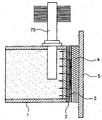
- FIG. 5 is a configuration diagram for an experimental example of a brake oil vapor lock reduction device according to the present invention.
- FIG. 1 is a block diagram of a vapor lock reduction device of a brake according to a first embodiment of the present invention
- Figure 2 is an enlarged view showing a heat pipe coupled to the hydraulic cylinder in FIG.
- the present invention can dissipate overheating of brake oil in real time without a separate operation by a driver, thereby reducing the vapor lock phenomenon and extending the life of the brake oil.
- the present invention relates to a vapor lock reduction device of a brake.
- the brake lock reduction device of the brake has a heat pipe 70 in the hydraulic cylinder 11 in the caliper 10 so that the brake oil may be vaporized by frictional heat with the brake disc 90 to reduce vapor lock phenomenon caused by bubbles. ) Is installed. More specifically, the evaporator 71 of the heat pipe 70 is embedded in the hydraulic cylinder 11 in the caliper 10, and the condensation unit 72 of the heat pipe 70 is exposed to the outside. A heat sink is provided on the outer circumferential surface of the portion 72 to cool the brake oil that is overheated.
- Vapor lock reduction device of such a brake is composed of four parts, which is composed of a caliper 10, the hydraulic supply line 30, the hydraulic return line 40 and the heat pipe (70).
- the caliper 10 is mounted on the brake disc 90 of the wheel, and two hydraulic cylinders 11 are formed therein to control the brake disc 90, and are interlocked by the respective hydraulic cylinders 11.
- the brake pad 20 is coupled to the structure.
- the hydraulic supply line 30 is connected to each hydraulic cylinder 11 in the caliper 10 from the master cylinder 50 connected to the brake pedal 60. At this time, the master cylinder 50 is connected to the oil reservoir 51 is a structure that receives the brake oil continuously.
- the hydraulic return line 40 is connected to the oil reservoir 51 to supply oil from the hydraulic cylinders 11 in the caliper 10 to the master cylinder 50. Therefore, when the brake pedal 60 is stepped on, the brake oil in the master cylinder 50 is pumped to the hydraulic cylinder 11 through the hydraulic supply line 30. If the brake pedal 60 is not stepped on, the elasticity of the brake pedal is restored. By the brake oil flows into the oil reservoir 51 through the hydraulic return line 40 by the hydraulic cylinder (11).
- the heat pipe 70 is intended to temporarily reduce the vapor lock phenomenon when the brake oil absorbs moisture over time due to hygroscopic.
- the heat pipe 70 functions to dissipate the overheated brake oil in the hydraulic cylinder 11 by partially inserting the evaporator 71 into each hydraulic cylinder 11.
- the heat pipe 70 is an evaporator 71 is inserted into each of the hydraulic cylinder 11 to reduce the overheating of the brake oil in each of the hydraulic cylinder 11, the condensation unit 72 By being configured to be exposed to the outside, it is configured to reduce the vapor lock phenomenon caused by the overheating of the oil in the hydraulic cylinder 11 to maintain a stable hydraulic pressure.
- the heat pipe 70 does not need a separate control configuration and performs heat dissipation in real time, it is easy to apply the device, and it is very inexpensive in terms of unit cost.
- a heat sink composed of a plurality of heat dissipation fins 721 is provided so as to facilitate heat dissipation.
- the heat sink can be configured to be mounted on the outer periphery of the heat pipe, and of course, can be configured integrally with the heat pipe.
- the piston P of the master cylinder 50 is operated to forcibly feed the brake oil to the hydraulic supply line 30.
- the brake oil flows into the hydraulic cylinder 11 in the caliper 10 through the hydraulic supply line 30, and the brake oil moves the piston P of the hydraulic cylinder 11 in the direction of the brake disc 90.
- the brake disc 90 is interrupted by friction between the brake disc 90 and the brake pad 20.
- the evaporator 71 of the heat pipe 70 embedded in the hydraulic cylinder 11 moves the frictional heat included in the brake oil to the condenser 72.
- the condenser 72 radiates heat to the outside through a plurality of heat dissipation fins 721 that are external heat sinks, thereby realizing that the brake oil is overheated in real time without a separate operation by the driver, and thus vapor lock.
- the phenomenon can be reduced, so that stable hydraulic pressure can be maintained.
- FIG. 3 is a block diagram of a vapor lock reduction device of a brake according to a second embodiment of the present invention
- Figure 4 is an enlarged view showing a heat pipe coupled to the hydraulic cylinder in FIG.
- the second embodiment of the present invention is configured to selectively detach the heat pipe 70 to the hydraulic cylinder 11 in the caliper 10.
- the hydraulic cylinder 11 of the second embodiment further includes a connecting means 80 for attaching and detaching the heat pipe 70.
- This configuration is for mounting the heat pipe 70 to temporarily reduce the vapor lock phenomenon when the brake oil absorbs moisture over time because the brake oil is hygroscopic.
- the connecting means 80 is screwed to the outer periphery of the fitting body 81 and the fitting body 81 integrally coupled to each of the hydraulic cylinders 11, the heat inserted into the fitting body 81 It consists of an open nut 82 comprising two ferrules that seal and grip the pipe 70.
- the fitting body 81 is integrally welded to the hydraulic cylinder 11 in which the brake oil is stored.
- a coupling hole (not shown) is formed in the hydraulic cylinder, and the fitting body is coupled to the coupling hole.
- Each of the ferrules 83 and 84 has a tapered surface formed at a lower outer periphery and an upper inner periphery, and is stacked on each other.
- the first ferrule 83 is disposed below the two ferrules 83 and 84 and pressed into the inner circumference of the fitting body 81.
- the first ferrule 83 functions to grip the outer circumference of the heat pipe 70 inserted into the fitting body 81 as the opening nut 82 is tightened.
- the second ferrule 84 is stacked on the upper inner circumferential edge of the first ferrule 83 and presses the first ferrule 83 as the open nut 82 is tightened, and simultaneously the outer circumferential edge of the heat pipe 70 is pressed. It serves as a seal.
- the heat pipe 70 can be mounted to temporarily reduce the vapor lock phenomenon before replacing the brake oil by providing the connecting means 80 in each hydraulic cylinder 11 in the caliper 10 in advance. It is a composition.
- the connecting means 80 can be quickly mounted to the heat pipe 70 when the brake operation is not smoothly operated by the vapor lock phenomenon, and after replacing the brake oil, the sealing nut to the fitting body 81 85 can be used in combination. (As shown in Fig. 4B).
- the opening nut 82 is inserted into the insertion end of the heat pipe 70, and the second ferrule 84 and the first ferrule 83 are sequentially inserted.
- the evaporator 71 which is an insertion end of the heat pipe 70, is inserted into the fitting body 81, so that the evaporator 71 of the heat pipe 70 exchanges heat with the brake oil in the hydraulic cylinder 11. It is inserted at an appropriate depth so as not to exceed the evaporation unit 71.
- the opening nut 82 is fastened to the fitting body 81 so that the first ferrule 83 and the second ferrule 84 grip and seal the heat pipe 70 by the pressure of the opening nut 82. do.
- FIG. 5 is a configuration diagram for an experimental example of a brake oil vapor lock reduction device according to the present invention.
- the evaporator of the heat pipe 70 is inserted into the chamber 1 in which the hydraulic cylinder is shaped, and the brake oil DOT-4 is filled in the chamber 1.
- a micro ceramic heater 3 having a size of 50 mm ⁇ 50 mm is attached to the right side of the chamber 1 to generate heat so that the brake pad may be overheated, and between the micro ceramic heater 3 and the chamber 1.
- a steel pad (AISI 304 stainless) (2) for transferring heat to the brake oil was installed, and configured by combining the heat insulating material (4) and the support plate (5) on the outside.
- the heater is heated up to about 350 ° C to change the temperature of the brake oil and the micro ceramic heater when the heat pipe is not mounted, and the temperature of the brake oil and the micro ceramic heater when the heat pipe is mounted.
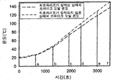
- the graph of FIG. 6 can be obtained.
- the blue line is a diagram when the heat pipe is mounted
- the red line is a diagram when the heat pipe is not mounted.
- the difference is not large at a lower heating temperature than when the heat pipe is not mounted.
- the temperature difference of the brake oil increases.
- the present invention is to provide a structure that can extend the life of the brake oil by heat radiation in real time that the brake oil is overheated through the heat pipe without a separate operation by the driver, thereby reducing the vapor lock phenomenon. .
Landscapes
- Engineering & Computer Science (AREA)
- Mechanical Engineering (AREA)
- General Engineering & Computer Science (AREA)
- Transportation (AREA)
- Braking Arrangements (AREA)
- Valves And Accessory Devices For Braking Systems (AREA)
Abstract
본 발명은 브레이크의 베이퍼록 감소장치에 관한 것으로, 이를 위해 내부에 2개의 유압실린더가 형성되고, 상기 각 유압실린더에 의해 연동되는 브레이크패드을 통해 브레이크디스크를 단속하는 캘리퍼;와, 차량의 브레이크페달과 연결된 마스터실린더에서 캘리퍼의 각 유압실린더로 연결되는 유압공급라인;과, 상기 캘리퍼의 각 유압실린더에서 마스터실린더로 브레이크오일을 공급할 수 있도록 오일리저버에 연결되는 유압리턴라인; 및 상기 캘리퍼의 각 유압실린더에 부분 삽입되어 유압실린더의 브레이크오일의 온도를 방열하는 히트파이프;를 포함하여 이루어지되, 상기 히트파이프는 상기 각 유압실린더 내의 브레이크오일이 과열되는 것을 방지할 수 있도록 증발부가 상기 각 유압실린더의 내부에 삽입되고, 응축부는 외부로 노출되게 구성함으로써, 유압실린더 내의 브레이크오일 과열에 따른 베이퍼록 현상을 감소시켜 안정된 유압을 유지시킬 수 있도록 구성되는 것을 특징으로 한다.
Description
본 발명은 운전자에 의한 별도의 조작없이도 브레이크오일이 과열되는 것을 실시간으로 방열하고, 이에 따른 베이퍼록 현상을 감소시킬 수 있는 브레이크의 베이퍼록 감소장치에 관한 것으로, 보다 상세하게는 캘리퍼 내 유압실린더에 히트파이프의 증발부를 매설하고, 히트파이프의 응축부를 외부로 노출시켜 구성하되, 응축부에 외주면에 히트싱크를 둠으로써 과열된 브레이크오일을 냉각시킬 수 있는 구조의 브레이크의 베이퍼록 감소장치에 관한 것이다.
일반적으로 차량의 브레이크 장치는 차량을 감속 또는 정지시킴과 더불어 주차상태를 유지하기 위해 사용되는 중요한 장치로서, 마찰력을 이용하여 차량의 운동에너지를 열에너지로 바꾸어, 그것을 대기속으로 방출시켜 브레이크 작용을 하는
마찰식 브레이크를 사용하고 있다.
상기와 같은 브레이크 장치는 주행할 때에 주로 사용하는 주 브레이크와, 자동차를 주차시킬 때에 사용하는 주차 브레이크가 있고, 상기 브레이크는 유압식 브레이크와 배력식 브레이크 및 공기 브레이크 등으로 구분되는 바, 상기 유압식 브레이크는 운전자의 브레이크페달 조작력을 마스터실린더에서 유압으로 전환하여 캘리퍼 내의 유압실린더로 전달하고, 유압실린더는 전달된 유압으로 브레이크패드를 회전하는 브레이크디스크에 밀착시켜 제동력을 발생시키게 되어 있다.
상기와 같은 유압식 브레이크에서 사용되는 브레이크 오일은 누유되지 않도록 적당한 점도와 윤활성을 갖기 위해 에틸렌글리코올, 폴리프로피렌, 폴리아르키린 등을 사용하고, 점도 조정용 용제로 알코올, 글리코올, 글리코올 에텔 등을 혼합하여 사용한다.
특히 베이퍼록이 일어나면 위험하기 때문에 비등점을 극히 중요시하지만, 브레이크를 자주 사용하게 되면 브레이크의 온도가 섭씨 수백도까지 상승할 뿐만 아니라 그 열이 브레이크 오일에도 전해져서 오일이 비등하여 기체가 발생하기도 한다.
일부 비흡습성의 브레이크오일이 존재하기는 하나, 일반적인 브레이크오일은 흡습성으로써 시간이 지남에 따라 수분을 흡수한다. 따라서 기체가 기포로 발전하게 되고, 이 기포는 쉽게 수축되면서 브레이크 압력을 원활하게 전달하지 못함으로 인해 브레이크 장치의 작동불능을 초래하게 된다.
이는 주행중 온도가 과도하게 상승하면 오일 내부에 흡수되어 있는 수분이 비등되어 유압이 전달되지 않음으로써 브레이크페달 조작시 스펀지를 밟는 것과 같은 스펀지 현상을 유발하는 베이퍼록(vapour lock) 현상이 발생하는 문제점이 있었다.
근래에 들어 오일온도상승으로 인한 베이퍼록 현상을 방지하기 위해 오일을 냉각시켜 주는 장치들이 개발/적용되어 있으나, 이들은 각각 전자적인 센서나 액츄에이터 및 이들을 제어하기 위한 전자제어유니트를 사용하고 있어서 별도의 동력 소모를 필요로 하고, 매우 복잡하며 설치가 용이하지 않다는 문제점이 있었다.
본 발명은 상기와 같은 문제점을 감안하여 안출된 것으로, 본 발명의 제 1목적은, 운전자에 의한 별도의 조작 없이도 브레이크오일이 과열되는 것을 실시간으로 방열하고, 이에 따른 베이퍼록 현상을 감소시킬 수가 있어 안정된 유압을 유지할 수 있으며, 또한 적정의 제동력이 지속적으로 유지할 수 있어 결과적으로 캘리퍼의 브레이크패드와 브레이크디스크의 내구성을 향상시킬 수 있는 구조의 브레이크의 베이퍼록 감소장치를 제공하는데 있다.
또한 본 발명의 제 2목적은, 캘리퍼 내의 유압실린더에 히트파이프의 증발부를 매설하고, 히트파이프의 응축부를 외부로 노출시켜 구성하되, 응축부에 외주면에 히트싱크를 둠으로써 과열된 브레이크오일을 실시간으로 냉각시킬 수 있는 브레이크의 베이퍼록 감소장치를 제공하는데 있다.
또한 본 발명의 제 3목적은, 별도의 제어구성이 필요하지 않고 실시간으로 방열을 행하기 때문에 장치의 적용이 용이하며, 적용 단가 측면에서도 매우 저렴한 구조의 브레이크의 베이퍼록 감소장치를 제공하는데 있다.
또한 본 발명이 제 4목적은, 베이퍼록 현상에 의해 브레이크 동작이 원활히 작동되지 않을 경우에는 히트파이프를 신속하게 장착시킬 수 있으며, 브레이크오일을 교환한 후에는 히트파이프를 탈착시켜 사용할 수 있는 구조의 브레이크의 베이퍼록 감소장치를 제공하는데 있다.
상기와 같은 목적을 달성하기 위한 본 발명의 제 1발명에 따른 브레이크의 베이퍼록 감소장치는 내부에 2개의 유압실린더가 형성되고, 상기 각 유압실린더에 의해 연동되는 브레이크패드을 통해 브레이크디스크를 단속하는 캘리퍼;와, 차량의 브레이크페달과 연결된 마스터실린더에서 캘리퍼의 각 유압실린더로 연결되는 유압공급라인;과, 상기 캘리퍼의 각 유압실린더에서 마스터실린더로 브레이크오일을 공급할 수 있도록 오일리저버에 연결되는 유압리턴라인; 및 상기 캘리퍼의 각 유압실린더에 부분 삽입되어 유압실린더의 브레이크오일의 온도를 방열하는 히트파이프;를 포함하여 이루어지되, 상기 히트파이프는 상기 각 유압실린더 내의 브레이크오일이 과열되는 것을 방지할 수 있도록 증발부가 상기 각 유압실린더의 내부에 삽입되고, 응축부는 외부로 노출되게 구성함으로써, 유압실린더 내의 브레이크오일 과열에 따른 베이퍼록 현상을 감소시켜 안정된 유압을 유지시킬 수 있도록 구성되는 것을 특징으로 한다.
제 2발명은, 제 1발명에서, 상기 응축부에는 다수의 방열핀으로 이루어지는 히트싱크가 형성된 것이 바람직하다.
제 3발명은, 제 2발명에서, 상기 캘리퍼의 각 유압실린더에는 상기 히트파이프를 탈부착하기 위한 연결수단을 더 포함하는 것이 바람직하다.
제 4발명은, 제 3발명에서, 상기 연결수단은 히트파이프가 삽입되고 상기 각 유압실린더에 일체로 결합된 이음쇠본체와, 상기 이음체 본체의 외주연에 나사체결되되 상기 이음쇠본체에 삽입된 히트파이프를 시일하고 파지하는 2개의 페룰을 포함하는 개방너트로 구성되는 것이 바람직하다.
본 발명의 브레이크의 베이퍼록 감소장치에 따르면, 운전자에 의한 별도의 조작 없이도 브레이크오일이 과열되는 것을 실시간으로 방열하고, 이에 따른 베이퍼록 현상을 감소시킬 수가 있어 안정된 유압을 유지할 수 있으며, 또한 적정의 제동력이 지속적으로 유지할 수 있어 결과적으로 캘리퍼의 브레이크패드와 브레이크디스크의 내구성을 향상시킬 수 있는 효과가 있다.
또한 캘리퍼 내의 유압실린더에 히트파이프의 증발부를 매설하고, 히트파이프의 응축부를 외부로 노출시켜 구성하되, 응축부에 외주면에 히트싱크를 둠으로써 과열된 브레이크오일을 실시간으로 냉각시킬 수 있어 별도의 제어구성이 필요하지 않고 실시간으로 방열을 행하기 때문에 장치의 적용이 용이하며, 적용 단가 측면에서도 매우 저렴한 효과가 있다.
또한 베이퍼록 현상에 의해 브레이크 동작이 원활히 작동되지 않을 경우에는 히트파이프를 신속하게 장착시킬 수 있으며, 브레이크오일을 교환한 후에는 히트파이프를 탈착시켜 사용할 수 있는 효과가 있다.
도 1은 본 발명의 제 1실시예에 따른 따른 브레이크의 베이퍼록 감소장치의 구성도,
도 2는 도 1에서 유압실린더에 결합된 히트파이프를 도시한 확대도이다.
도 3은 본 발명의 제 2실시예에 따른 따른 브레이크의 베이퍼록 감소장치의 구성도,
도 4는 도 3에서 유압실린더에 결합된 히트파이프를 도시한 확대도이다.
도 5는 본 발명에 따른 브레이크오일 베이퍼록 감소장치의 실험예를 위한 구성도,
도 6은 실험예의 결과에 따른 선도 그래프이다.
이하에서는 본 발명에 따른 브레이크의 베이퍼록 감소장치에 관하여 첨부되어진 도면과 함께 더불어 상세히 설명하기로 한다.
[실시예 1]
도 1은 본 발명의 제 1실시예에 따른 따른 브레이크의 베이퍼록 감소장치의 구성도이고, 도 2는 도 1에서 유압실린더에 결합된 히트파이프를 도시한 확대도이다.
도 1 및 도 2에 도시된 바와 같이, 본 발명은 운전자에 의한 별도의 조작없이도 브레이크오일이 과열되는 것을 실시간으로 방열하고, 이에 따른 베이퍼록 현상을 감소시킬 수 있어 브레이크오일의 수명을 연장시킬 수 있는 브레이크의 베이퍼록 감소장치에 관한 것이다.
이러한 브레이크의 베이퍼록 감소장치는 브레이크디스크(90)와의 마찰열에 의해 브레이크오일이 기화되어 기포로 인해 발생하는 베이퍼록 현상을 감소할 수 있도록 캘리퍼(10) 내의 유압실린더(11)에 히트파이프(70)를 장착한 구조이다. 보다 상세하게는 캘리퍼(10) 내의 유압실린더(11)에 히트파이프(70)의 증발부(71)를 매설하고, 히트파이프(70)의 응축부(72)를 외부로 노출시켜 구성하되, 응축부(72)에 외주면에 히트싱크를 둠으로써 과열된 브레이크오일을 냉각시키는 장치이다.
이러한 브레이크의 베이퍼록 감소장치 크게 4부분으로 구성되는데, 이는 캘리퍼(10)와, 유압공급라인(30)과, 유압리턴라인(40) 및 히트파이프(70)로 구성된다.
여기서 캘리퍼(10)는 차륜의 브레이크디스크(90)에 장착되며, 상기 브레이크디스크(90)를 단속하기 위해 내부에 2개의 유압실린더(11)가 형성되고, 상기 각 유압실린더(11)에 의해 연동되는 브레이크패드(20)가 결합되어 있는 구조이다.
그리고 상기 유압공급라인(30)은 브레이크페달(60)과 연결된 마스터실린더(50)에서 캘리퍼(10) 내의 각 유압실린더(11)로 연결되는 구조이다. 이 때 상기 마스터실린더(50)는 오일리저버(51)에 연결되어 브레이크오일을 지속적으로 공급받는 구조이다.
한편 상기 유압리턴라인(40)은 상기 캘리퍼(10) 내의 각 유압실린더(11)에서 마스터실린더(50)로 오일을 공급할 수 있도록 오일리저버(51)에 연결된다. 따라서 브레이크페달(60)을 밟으면 상기 마스터실린더(50) 내의 브레이크오일은 유압공급라인(30)을 통해 상기 유압실린더(11)로 압송하게 되고, 브레이크페달(60)을 밟지 않으면 브레이크페달의 탄성복귀에 의해 유압실린더(11) 내에 브레이크오일이 유압리턴라인(40)을 통해 오일리저버(51)로 유입된다.
한편 상기 히트파이프(70)는 브레이크오일이 흡습성(Hygroscopic)으로 시간이 지남에 따라 수분을 흡수할 경우, 임시적으로 베이퍼록 현상을 감소하기 위한 것이다. 이러한 상기 히트파이프(70)는 각 유압실린더(11)에 증발부(71)가 부분 삽입되어 유압실린더(11) 내의 과열된 브레이크오일을 방열하는 기능을 한다.
상기 히트파이프(70)는 상기 각 유압실린더(11) 내의 브레이크오일이 과열되는 것을 감소할 수 있도록 증발부(71)가 상기 각 유압실린더(11)의 내부에 삽입되고, 응축부(72)는 외부로 노출되게 구성함으로써, 유압실린더(11) 내의 오일 과열에 따른 베이퍼록 현상을 감소시켜 안정된 유압을 유지시킬 수 있도록 구성된다.
이러한 상기 히트파이프(70)는 별도의 제어구성이 필요하지 않고 실시간으로 방열을 행하기 때문에 장치의 적용이 용이하며, 적용 단가 측면에서도 매우 저렴한 특징이 있다.
상기에서 히트파이프(70)의 응축부(72)에는 방열을 원활히 할 수 있도록 다수의 방열핀(721)으로 이루어지는 히트싱크가 외장된 구조이다. 이러한 히트싱크는 히트파이프의 외주연에 장착가능하게 구성할 수 있으며, 이외에 히트파이프와 일체로 구성할 수 있음은 물론이다.
이하에서는 본 발명에 따른 브레이크의 베이퍼록 감소장치의 작동에 관하여 간단히 설명하기로 한다.
운전자가 빠른 속도록 차량을 주행시키다 브레이크페달(60)을 밟게 되면 마스터실린더(50)의 피스톤(P)이 작동하여 브레이크오일을 유압공급라인(30)으로 강제 압송한다.
이 후 브레이크오일은 유압공급라인(30)을 통해 캘리퍼(10) 내의 유압실린더(11)로 유입되고, 상기 브레이크오일은 유압실린더(11)의 피스톤(P)이 브레이크디스크(90) 방향으로 이동되어 브레이크디스크(90)와 브레이크패드(20) 간의 마찰에 의해 브레이크디스크(90)를 단속하게 된다.
이 때 브레이크디스크(90)와 브레이크패드(20) 간의 마찰열은 상기 브레이크패드(20)를 작동시키는 캘리퍼(10) 내의 유압실린더(11)로 전달되어 브레이크오일이 가열되는 현상을 발생시키게 된다.
그러면 상기 유압실린더(11)에 매립된 히트파이프(70)의 증발부(71)는 브레이크오일에 포함된 마찰열을 응축부(72)로 이동시키게 된다.
이 후 응축부(72)에서는 외장된 히트싱크인 다수의 방열핀(721)을 통해 외부로 열을 방열시키게 되어 운전자에 의한 별도의 조작 없이도 브레이크오일이 과열되는 것을 실시간으로 방열하고, 이에 따른 베이퍼록 현상을 감소시킬 수가 있어 안정된 유압을 유지시킬 수 있다.
이는 브레이크오일을 온도를 항시적으로 균일하게 유지할 수 있게 되므로, 적정의 제동력이 유지할 수 있고, 결과적으로 캘리퍼(10)의 브레이크패드(20)와 브레이크디스크(90)의 내구성을 향상시키게 된다.
[실시예 2]
도 3은 본 발명의 제 2실시예에 따른 따른 브레이크의 베이퍼록 감소장치의 구성도이고, 도 4는 도 3에서 유압실린더에 결합된 히트파이프를 도시한 확대도이다.
도 3 및 도 4에 도시된 바와 같이, 본 발명의 제 2실시예는 캘리퍼(10) 내의 유압실린더(11)에 히트파이프(70)를 선택적으로 탈부착가능 하게 구성된다.
이를 위해 제 2실시예의 유압실린더(11)에는 상기 히트파이프(70)를 탈부착하기 위한 연결수단(80)을 더 포함하는 구성이다.
이러한 구성은 브레이크오일이 흡습성으로써, 시간이 지남에 따라 브레이크오일이 수분을 흡수할 경우, 임시로 베이퍼록 현상을 감소하기 위해 히트파이프(70)를 장착하기 위한 것이다.
상기 연결수단(80)은 상기 각 유압실린더(11)에 일체로 결합된 이음쇠몸체(81)와, 상기 이음쇠몸체(81)의 외주연에 나사체결되되, 상기 이음쇠몸체(81)에 삽입된 히트파이프(70)를 시일하고 파지하는 2개의 페룰(ferrule)을 포함하는 개방너트(82)로 구성된다.
여기서 이음쇠몸체(81)는 브레이크오일이 저장된 유압실린더(11)에 일체로 용접결합되어 구성되며, 이외에 유압실린더에 결합홀(미도시)을 형성하고, 상기 결합홀에 이음쇠본체를 체결결합시켜 구성할 수 있음은 물론이다.
그리고 상기 각 페룰(83,84)은 하부 외주연 및 상부 내주연에 테이퍼면이 형성되어 있으며, 상호 적층되어 있는 구성이다.
여기서 2개의 페룰(83,84) 중 하부에 배치되어 상기 이음쇠몸체(81)의 내주연에 압입되는 것이 제 1페룰(83)이다. 이러한 제 1페룰(83)은 개방너트(82)의 조임에 따라 이음쇠몸체(81)에 삽입된 히트파이프(70)의 외주연을 파지하는 기능을 한다.
그리고 상기 제 2페룰(84)은 제 1페룰(83)의 상부 내주연 적층되어 개방너트(82)의 조임에 따라 제 1페룰(83)의 압박하고, 동시에 히트파이프(70)의 외주연을 시일하는 기능을 한다.
이와 같은 구성은 캘리퍼(10) 내의 각 유압실린더(11)에 연결수단(80)을 미리 마련함으로써, 브레이크오일을 교환하기 전에 일시적으로 베이퍼록 현상을 감소하기 위해 히트파이프(70)를 장착할 수 있는 구성이다.
여기서 상기 연결수단(80)은 베이퍼록 현상에 의해 브레이크 동작이 원활히 작동되지 않을 경우에는 히트파이프(70)를 신속하게 장착시킬 수 있으며, 브레이크오일을 교환한 후에는 이음쇠몸체(81)에 패쇄너트(85)를 결합시켜 사용할 수 있다.(도 4의 (b)에 도시)
이하에서는 본 발명의 제 2실시예에 따른 히트파이프의 장착에 관하여 간단히 설명하기로 한다.
먼저 캘리퍼(10)의 유압실린더(11)에 구비된 이음쇠몸체(81)에 결합된 패쇄너트(85)를 탈거 한다.
그리고 히트파이프(70)의 삽입단부에 개방너트(82)를 삽입하고, 제 2페룰(84)과 제 1페룰(83)을 순차적으로 삽입한다.
이 후 상기 히트파이프(70)의 삽입단부인 증발부(71)를 이음쇠몸체(81)에 삽입시키되, 히트파이프(70)의 증발부(71)가 유압실린더(11) 내의 브레이크오일과 열교환되도록 증발부(71)를 넘지 않도록 적절한 깊이로 삽입한다.
마지막으로 상기 개방너트(82)를 이음쇠몸체(81)에 체결하여 개방너트(82)의 압박으로 제 1페룰(83)과 제 2페룰(84)이 상기 히트파이프(70)를 파지하고 시일되도록 한다.
[실험예]
이하에서는 본원발명에 따른 브레이크의 베이퍼록 감소장치의 검증실험에 대해 간단히 설명하기로 한다.
도 5는 본 발명에 따른 브레이크오일 베이퍼록 감소장치의 실험예를 위한 구성도이다.
도 5와 같이, 유압실린더를 형상화한 챔버(1)에 히트파이프(70)의 증발부를 삽입하여 고정하고, 챔버(1)의 내부에는 브레이크오일(DOT-4)을 충진시켜 구성하였다.
그리고 챔버(1)의 오른쪽 측면에는 브레이크패드의 과열을 구현할 수 있도록 열을 발생시키기 위한 50mm × 50mm 크기의 마이크로세라믹히터(3)를 부착하고, 마이크로세라믹히터(3)와 챔버(1)의 사이에는 열을 브레이크오일로 전달시키기 위한 스틸패드(AISI 304 stainless)(2)를 설치하고, 외측으로는 단열재(4)와 지지판(5)을 결합시켜 구성하였다.
이 후 아래의 [표 1]과 같이 실험조건은 히트파이프가 장착되지 않을 경우와, 히트파이프가 장착된 경우에 대해 동일 조건 하에 각각 수행되었고 외부공기의 유동은 없으며, 열유속과 히터의 가열시간은 아래표와 같다.
표 1
| 구분 | 열유속(W/㎠) | 가열시간(min) |
| 1 | 1 | 10 |
| 2 | 5 | 10 |
| 3 | 10 | 10 |
| 4 | 12 | 8 |
| 5 | 15 | 10 |
| 6 | 18 | 9 |
이 후 히터의 온도를 최고 약 350℃로 가열하여, 히트파이프가 장착되지 않을 경우의 브레이크오일 및 마이크로 세라믹 히터의 온도변화와, 히트파이프가 장착되었을 경우의 브레이크오일 및 마이크로세라믹히터의 온도변화 온도변화를 관찰한 결과, [도 6]의 그래프를 획득할 수 있다.
[도 6]에서 청색선은 히트파이프가 장착된 경우의 선도이고, 적색선은 히트파이프가 장착되지 않은 경우의 선도이다. 이러한 두개의 선도는 히터의 온도가 높을 수록 간격이 넓어지는 것을 알 수 있었으며, 이러한 간격 차에 의한 온도차는 아래의 [표 2]를 보면 구체적으로 알 수 있다.
표 2
| 위치 | 온도차이(℃) |
| ⓐ | 0.6 |
| ⓑ | 2.2 |
| ⓒ | 4.8 |
| ⓓ | 7.8 |
| ⓔ | 10.4 |
| ⓕ | 13.3 |
즉, 히트파이프가 장착된 경우가 히트파이프가 장착되지 않은 경우보다 낮은 가열온도에서는 차이가 크지 않으나, 히터의 가열온도가 증가할수록 브레이크오일의 온도차이가 커지는 것을 확인할 수 있었다.
실제 베이퍼락이 발생하는 시점에서 히터의 온도가 500℃이상인 것을 감안한다면, 본 실험결과보다 두 장치에 대한 브레이크오일의 온도차이가 더 커질 수 있다는 것을 확인할 수 있다.
또한, 자동차의 경우 베이퍼락은 주행 중에 발생함으로 외부유동이 존재하지만, 본 실험장치에서는 히트싱크의 냉각에 도움을 줄 수 있는 외부유동을 발생시키지 않았다. 그러므로 실제 자동차에 본원발명을 장착할 경우 실험에서 나온 결과보다 냉각효과가 증가할 것으로 판단된다.
때문에 본원발명은 운전자에 의한 별도의 조작 없이도 히트파이프를 통해 브레이크오일이 과열되는 것을 실시간으로 방열하고, 이에 따른 베이퍼록 현상을 감소시킬 수 있어 브레이크오일의 수명을 연장시킬 수 있는 구조가 마련되는 것이다.
본 발명은 첨부된 도면을 참조하여 바람직한 실시예를 중심으로 기술되었지만 당업자라면 이러한 기재로부터 본 발명의 범주를 벗어남이 없이 다양한 자명한 변형이 가능하다는 것을 명백하다. 따라서 본 발명의 범주는 이러한 많은 변형예들을 포함하도록 기술된 청구범위에 의해서 해석되어야 한다.
Claims (4)
- 내부에 2개의 유압실린더(11)가 형성되고, 상기 각 유압실린더(11)에 의해 연동되는 브레이크패드(20)을 통해 브레이크디스크(90)를 단속하는 캘리퍼;차량의 브레이크페달(60)과 연결된 마스터실린더(50)에서 캘리퍼(10)의 각 유압실린더(11)로 연결되는 유압공급라인(30);상기 캘리퍼(10)의 각 유압실린더(11)에서 마스터실린더(50)로 브레이크오일을 공급할 수 있도록 오일리저버(51)에 연결되는 유압리턴라인(40); 및상기 캘리퍼(10)의 각 유압실린더(11)에 부분 삽입되어 유압실린더(11)의 브레이크오일의 온도를 방열하는 히트파이프(70);를 포함하여 이루어지되,상기 히트파이프(70)는 상기 각 유압실린더(11) 내의 브레이크오일이 과열되는 것을 방지할 수 있도록 증발부(71)가 상기 각 유압실린더(11)의 내부에 삽입되고, 응축부(72)는 외부로 노출되게 구성함으로써, 유압실린더(11) 내의 브레이크오일 과열에 따른 베이퍼록 현상을 감소시켜 안정된 유압을 유지시킬 수 있도록 구성되는 것을 특징으로 하는 브레이크의 베이퍼록 감소장치.
- 제 1항에 있어서,상기 응축부(72)에는 다수의 방열핀(721)으로 이루어지는 히트싱크가 형성된 것을 특징으로 하는 브레이크의 베이퍼록 감소장치.
- 제 2항에 있어서,상기 캘리퍼(10)의 각 유압실린더(11)에는 상기 히트파이프(70)를 탈부착하기 위한 연결수단(80)을 더 포함하는 것을 특징으로 하는 브레이크의 베이퍼록 감소장치.
- 제 3항에 있어서,상기 연결수단(80)은 히트파이프(70)가 삽입되고 상기 각 유압실린더(11)에 일체로 결합된 이음쇠몸체(81)와, 상기 이음쇠몸체(81)의 외주연에 나사체결되되, 상기 이음쇠몸체(81)에 삽입된 히트파이프(70)를 시일하고 파지하는 2개의 페룰(83,84)을 포함하는 개방너트(82)로 구성된 것을 특징으로 하는 브레이크의 베이퍼록 감소장치.
Applications Claiming Priority (2)
| Application Number | Priority Date | Filing Date | Title |
|---|---|---|---|
| KR1020100130108A KR20120068471A (ko) | 2010-12-17 | 2010-12-17 | 브레이크의 베이퍼록 감소장치 |
| KR10-2010-0130108 | 2010-12-17 |
Publications (1)
| Publication Number | Publication Date |
|---|---|
| WO2012081822A1 true WO2012081822A1 (ko) | 2012-06-21 |
Family
ID=46244888
Family Applications (1)
| Application Number | Title | Priority Date | Filing Date |
|---|---|---|---|
| PCT/KR2011/008072 Ceased WO2012081822A1 (ko) | 2010-12-17 | 2011-10-27 | 브레이크의 베이퍼록 감소장치 |
Country Status (2)
| Country | Link |
|---|---|
| KR (1) | KR20120068471A (ko) |
| WO (1) | WO2012081822A1 (ko) |
Cited By (2)
| Publication number | Priority date | Publication date | Assignee | Title |
|---|---|---|---|---|
| CN108443372A (zh) * | 2018-06-05 | 2018-08-24 | 安徽东立汽车部件有限公司 | 一种制动卡钳 |
| AT526073B1 (de) * | 2022-09-21 | 2023-11-15 | Dobrovz Thomas | Bremsenkühlung |
Families Citing this family (1)
| Publication number | Priority date | Publication date | Assignee | Title |
|---|---|---|---|---|
| US20240175814A1 (en) | 2021-03-31 | 2024-05-30 | Maruzen Petrochemical Co., Ltd. | Method for evaluating resist polymer |
Citations (5)
| Publication number | Priority date | Publication date | Assignee | Title |
|---|---|---|---|---|
| JPS62133909U (ko) * | 1986-02-17 | 1987-08-24 | ||
| JPH0558438U (ja) * | 1992-01-23 | 1993-08-03 | 三菱電線工業株式会社 | エンジンオイルの冷却装置 |
| JPH0798054A (ja) * | 1993-09-29 | 1995-04-11 | Hino Motors Ltd | トランスミッションオイルの冷却装置 |
| KR19990008341U (ko) * | 1997-08-01 | 1999-03-05 | 정몽규 | 자동차용 디스크 브레이크의 냉각장치 |
| KR20080053433A (ko) * | 2006-12-10 | 2008-06-13 | 현대자동차주식회사 | 브레이크 오일 성능 유지장치 |
-
2010
- 2010-12-17 KR KR1020100130108A patent/KR20120068471A/ko not_active Ceased
-
2011
- 2011-10-27 WO PCT/KR2011/008072 patent/WO2012081822A1/ko not_active Ceased
Patent Citations (5)
| Publication number | Priority date | Publication date | Assignee | Title |
|---|---|---|---|---|
| JPS62133909U (ko) * | 1986-02-17 | 1987-08-24 | ||
| JPH0558438U (ja) * | 1992-01-23 | 1993-08-03 | 三菱電線工業株式会社 | エンジンオイルの冷却装置 |
| JPH0798054A (ja) * | 1993-09-29 | 1995-04-11 | Hino Motors Ltd | トランスミッションオイルの冷却装置 |
| KR19990008341U (ko) * | 1997-08-01 | 1999-03-05 | 정몽규 | 자동차용 디스크 브레이크의 냉각장치 |
| KR20080053433A (ko) * | 2006-12-10 | 2008-06-13 | 현대자동차주식회사 | 브레이크 오일 성능 유지장치 |
Cited By (3)
| Publication number | Priority date | Publication date | Assignee | Title |
|---|---|---|---|---|
| CN108443372A (zh) * | 2018-06-05 | 2018-08-24 | 安徽东立汽车部件有限公司 | 一种制动卡钳 |
| AT526073B1 (de) * | 2022-09-21 | 2023-11-15 | Dobrovz Thomas | Bremsenkühlung |
| AT526073A4 (de) * | 2022-09-21 | 2023-11-15 | Dobrovz Thomas | Bremsenkühlung |
Also Published As
| Publication number | Publication date |
|---|---|
| KR20120068471A (ko) | 2012-06-27 |
Similar Documents
| Publication | Publication Date | Title |
|---|---|---|
| WO2012081822A1 (ko) | 브레이크의 베이퍼록 감소장치 | |
| US20160143186A1 (en) | Heatpipe imbedded coldplate enhancing igbt heat spreading | |
| CN205001421U (zh) | 一种液压回位多盘湿式制动器 | |
| WO2020145644A1 (ko) | 고방열 연성회로기판(gfpcb) 및 이의 제조 방법, 차량용 led 램프 | |
| CN109372915A (zh) | 一种带散热功能的制动鼓 | |
| GB801073A (en) | Fluid pressure brake system | |
| CN204253683U (zh) | 车用刹车卡钳结构 | |
| WO2018012659A1 (ko) | 차량용 빔프로젝터 방열 장치 | |
| TW200730741A (en) | High thermal transfer caliper | |
| ATE475815T1 (de) | Scheibenbremsbelag mit verringerter wärmeübertragung an eine zuspanneinheit | |
| WO2013169033A1 (ko) | 엘이디 조명기구용 방열장치 | |
| WO2016003088A1 (ko) | 액체금속 열교환부를 포함한 열전 발전장치 | |
| CN106004819B (zh) | 汽车制动器 | |
| CN210107093U (zh) | 一种高散热的led发光二极管 | |
| KR101700429B1 (ko) | 베이퍼록 방지를 위한 브레이크의 냉각장치 | |
| JPH04219534A (ja) | ディスクブレーキ | |
| JPS6267337A (ja) | デイスクブレ−キの冷却装置 | |
| CN212479974U (zh) | 一种散热刹车片以及一种可散热的制动钳 | |
| CN213117221U (zh) | 一种有利于散热的盘式制动器的制动衬块 | |
| CN207984838U (zh) | 一种汽车制动装置 | |
| TWM436108U (en) | Brake lining having heat dissipation function | |
| CN218468130U (zh) | 一种快速刹车型碟刹 | |
| CN216591505U (zh) | 一种新型汽车led灯 | |
| WO2020067807A1 (ko) | 전자제어장치의 조립구조 | |
| GB2449201A (en) | Braking systems with cooling |
Legal Events
| Date | Code | Title | Description |
|---|---|---|---|
| 121 | Ep: the epo has been informed by wipo that ep was designated in this application |
Ref document number: 11849430 Country of ref document: EP Kind code of ref document: A1 |
|
| NENP | Non-entry into the national phase |
Ref country code: DE |
|
| 122 | Ep: pct application non-entry in european phase |
Ref document number: 11849430 Country of ref document: EP Kind code of ref document: A1 |