WO2012073719A1 - 熱交換器及びそれを搭載した一体型空気調和機 - Google Patents
熱交換器及びそれを搭載した一体型空気調和機 Download PDFInfo
- Publication number
- WO2012073719A1 WO2012073719A1 PCT/JP2011/076572 JP2011076572W WO2012073719A1 WO 2012073719 A1 WO2012073719 A1 WO 2012073719A1 JP 2011076572 W JP2011076572 W JP 2011076572W WO 2012073719 A1 WO2012073719 A1 WO 2012073719A1
- Authority
- WO
- WIPO (PCT)
- Prior art keywords
- heat exchanger
- heat
- refrigerant
- heat exchange
- flat tubes
- Prior art date
- Legal status (The legal status is an assumption and is not a legal conclusion. Google has not performed a legal analysis and makes no representation as to the accuracy of the status listed.)
- Ceased
Links
Images


Classifications
-
- F—MECHANICAL ENGINEERING; LIGHTING; HEATING; WEAPONS; BLASTING
- F25—REFRIGERATION OR COOLING; COMBINED HEATING AND REFRIGERATION SYSTEMS; HEAT PUMP SYSTEMS; MANUFACTURE OR STORAGE OF ICE; LIQUEFACTION SOLIDIFICATION OF GASES
- F25B—REFRIGERATION MACHINES, PLANTS OR SYSTEMS; COMBINED HEATING AND REFRIGERATION SYSTEMS; HEAT PUMP SYSTEMS
- F25B39/00—Evaporators; Condensers
-
- F—MECHANICAL ENGINEERING; LIGHTING; HEATING; WEAPONS; BLASTING
- F28—HEAT EXCHANGE IN GENERAL
- F28D—HEAT-EXCHANGE APPARATUS, NOT PROVIDED FOR IN ANOTHER SUBCLASS, IN WHICH THE HEAT-EXCHANGE MEDIA DO NOT COME INTO DIRECT CONTACT
- F28D1/00—Heat-exchange apparatus having stationary conduit assemblies for one heat-exchange medium only, the media being in contact with different sides of the conduit wall, in which the other heat-exchange medium is a large body of fluid, e.g. domestic or motor car radiators
- F28D1/02—Heat-exchange apparatus having stationary conduit assemblies for one heat-exchange medium only, the media being in contact with different sides of the conduit wall, in which the other heat-exchange medium is a large body of fluid, e.g. domestic or motor car radiators with heat-exchange conduits immersed in the body of fluid
- F28D1/04—Heat-exchange apparatus having stationary conduit assemblies for one heat-exchange medium only, the media being in contact with different sides of the conduit wall, in which the other heat-exchange medium is a large body of fluid, e.g. domestic or motor car radiators with heat-exchange conduits immersed in the body of fluid with tubular conduits
- F28D1/0408—Multi-circuit heat exchangers, e.g. integrating different heat exchange sections in the same unit or heat exchangers for more than two fluids
-
- F—MECHANICAL ENGINEERING; LIGHTING; HEATING; WEAPONS; BLASTING
- F28—HEAT EXCHANGE IN GENERAL
- F28D—HEAT-EXCHANGE APPARATUS, NOT PROVIDED FOR IN ANOTHER SUBCLASS, IN WHICH THE HEAT-EXCHANGE MEDIA DO NOT COME INTO DIRECT CONTACT
- F28D1/00—Heat-exchange apparatus having stationary conduit assemblies for one heat-exchange medium only, the media being in contact with different sides of the conduit wall, in which the other heat-exchange medium is a large body of fluid, e.g. domestic or motor car radiators
- F28D1/02—Heat-exchange apparatus having stationary conduit assemblies for one heat-exchange medium only, the media being in contact with different sides of the conduit wall, in which the other heat-exchange medium is a large body of fluid, e.g. domestic or motor car radiators with heat-exchange conduits immersed in the body of fluid
- F28D1/04—Heat-exchange apparatus having stationary conduit assemblies for one heat-exchange medium only, the media being in contact with different sides of the conduit wall, in which the other heat-exchange medium is a large body of fluid, e.g. domestic or motor car radiators with heat-exchange conduits immersed in the body of fluid with tubular conduits
- F28D1/0408—Multi-circuit heat exchangers, e.g. integrating different heat exchange sections in the same unit or heat exchangers for more than two fluids
- F28D1/0417—Multi-circuit heat exchangers, e.g. integrating different heat exchange sections in the same unit or heat exchangers for more than two fluids with particular circuits for the same heat exchange medium, e.g. with the heat exchange medium flowing through sections having different heat exchange capacities or for heating/cooling the heat exchange medium at different temperatures
-
- F—MECHANICAL ENGINEERING; LIGHTING; HEATING; WEAPONS; BLASTING
- F28—HEAT EXCHANGE IN GENERAL
- F28D—HEAT-EXCHANGE APPARATUS, NOT PROVIDED FOR IN ANOTHER SUBCLASS, IN WHICH THE HEAT-EXCHANGE MEDIA DO NOT COME INTO DIRECT CONTACT
- F28D1/00—Heat-exchange apparatus having stationary conduit assemblies for one heat-exchange medium only, the media being in contact with different sides of the conduit wall, in which the other heat-exchange medium is a large body of fluid, e.g. domestic or motor car radiators
- F28D1/02—Heat-exchange apparatus having stationary conduit assemblies for one heat-exchange medium only, the media being in contact with different sides of the conduit wall, in which the other heat-exchange medium is a large body of fluid, e.g. domestic or motor car radiators with heat-exchange conduits immersed in the body of fluid
- F28D1/04—Heat-exchange apparatus having stationary conduit assemblies for one heat-exchange medium only, the media being in contact with different sides of the conduit wall, in which the other heat-exchange medium is a large body of fluid, e.g. domestic or motor car radiators with heat-exchange conduits immersed in the body of fluid with tubular conduits
- F28D1/0408—Multi-circuit heat exchangers, e.g. integrating different heat exchange sections in the same unit or heat exchangers for more than two fluids
- F28D1/0426—Multi-circuit heat exchangers, e.g. integrating different heat exchange sections in the same unit or heat exchangers for more than two fluids with units having particular arrangement relative to the large body of fluid, e.g. with interleaved units or with adjacent heat exchange units in common air flow or with units extending at an angle to each other or with units arranged around a central element
- F28D1/0443—Combination of units extending one beside or one above the other
-
- F—MECHANICAL ENGINEERING; LIGHTING; HEATING; WEAPONS; BLASTING
- F28—HEAT EXCHANGE IN GENERAL
- F28D—HEAT-EXCHANGE APPARATUS, NOT PROVIDED FOR IN ANOTHER SUBCLASS, IN WHICH THE HEAT-EXCHANGE MEDIA DO NOT COME INTO DIRECT CONTACT
- F28D1/00—Heat-exchange apparatus having stationary conduit assemblies for one heat-exchange medium only, the media being in contact with different sides of the conduit wall, in which the other heat-exchange medium is a large body of fluid, e.g. domestic or motor car radiators
- F28D1/02—Heat-exchange apparatus having stationary conduit assemblies for one heat-exchange medium only, the media being in contact with different sides of the conduit wall, in which the other heat-exchange medium is a large body of fluid, e.g. domestic or motor car radiators with heat-exchange conduits immersed in the body of fluid
- F28D1/04—Heat-exchange apparatus having stationary conduit assemblies for one heat-exchange medium only, the media being in contact with different sides of the conduit wall, in which the other heat-exchange medium is a large body of fluid, e.g. domestic or motor car radiators with heat-exchange conduits immersed in the body of fluid with tubular conduits
- F28D1/053—Heat-exchange apparatus having stationary conduit assemblies for one heat-exchange medium only, the media being in contact with different sides of the conduit wall, in which the other heat-exchange medium is a large body of fluid, e.g. domestic or motor car radiators with heat-exchange conduits immersed in the body of fluid with tubular conduits the conduits being straight
- F28D1/0535—Heat-exchange apparatus having stationary conduit assemblies for one heat-exchange medium only, the media being in contact with different sides of the conduit wall, in which the other heat-exchange medium is a large body of fluid, e.g. domestic or motor car radiators with heat-exchange conduits immersed in the body of fluid with tubular conduits the conduits being straight the conduits having a non-circular cross-section
- F28D1/05366—Assemblies of conduits connected to common headers, e.g. core type radiators
- F28D1/05375—Assemblies of conduits connected to common headers, e.g. core type radiators with particular pattern of flow, e.g. change of flow direction
-
- F—MECHANICAL ENGINEERING; LIGHTING; HEATING; WEAPONS; BLASTING
- F28—HEAT EXCHANGE IN GENERAL
- F28F—DETAILS OF HEAT-EXCHANGE AND HEAT-TRANSFER APPARATUS, OF GENERAL APPLICATION
- F28F9/00—Casings; Header boxes; Auxiliary supports for elements; Auxiliary members within casings
- F28F9/02—Header boxes; End plates
- F28F9/0202—Header boxes having their inner space divided by partitions
- F28F9/0204—Header boxes having their inner space divided by partitions for elongated header box, e.g. with transversal and longitudinal partitions
- F28F9/0209—Header boxes having their inner space divided by partitions for elongated header box, e.g. with transversal and longitudinal partitions having only transversal partitions
-
- F—MECHANICAL ENGINEERING; LIGHTING; HEATING; WEAPONS; BLASTING
- F28—HEAT EXCHANGE IN GENERAL
- F28D—HEAT-EXCHANGE APPARATUS, NOT PROVIDED FOR IN ANOTHER SUBCLASS, IN WHICH THE HEAT-EXCHANGE MEDIA DO NOT COME INTO DIRECT CONTACT
- F28D1/00—Heat-exchange apparatus having stationary conduit assemblies for one heat-exchange medium only, the media being in contact with different sides of the conduit wall, in which the other heat-exchange medium is a large body of fluid, e.g. domestic or motor car radiators
- F28D1/02—Heat-exchange apparatus having stationary conduit assemblies for one heat-exchange medium only, the media being in contact with different sides of the conduit wall, in which the other heat-exchange medium is a large body of fluid, e.g. domestic or motor car radiators with heat-exchange conduits immersed in the body of fluid
- F28D2001/0253—Particular components
- F28D2001/026—Cores
- F28D2001/028—Cores with empty spaces or with additional elements integrated into the cores
-
- F—MECHANICAL ENGINEERING; LIGHTING; HEATING; WEAPONS; BLASTING
- F28—HEAT EXCHANGE IN GENERAL
- F28D—HEAT-EXCHANGE APPARATUS, NOT PROVIDED FOR IN ANOTHER SUBCLASS, IN WHICH THE HEAT-EXCHANGE MEDIA DO NOT COME INTO DIRECT CONTACT
- F28D21/00—Heat-exchange apparatus not covered by any of the groups F28D1/00 - F28D20/00
- F28D2021/0019—Other heat exchangers for particular applications; Heat exchange systems not otherwise provided for
- F28D2021/0068—Other heat exchangers for particular applications; Heat exchange systems not otherwise provided for for refrigerant cycles
-
- F—MECHANICAL ENGINEERING; LIGHTING; HEATING; WEAPONS; BLASTING
- F28—HEAT EXCHANGE IN GENERAL
- F28F—DETAILS OF HEAT-EXCHANGE AND HEAT-TRANSFER APPARATUS, OF GENERAL APPLICATION
- F28F2270/00—Thermal insulation; Thermal decoupling
Definitions
- the present invention relates to a side flow type parallel flow type heat exchanger and an integrated air conditioner equipped with the same.
- a parallel flow type heat in which a plurality of flat tubes are arranged between a plurality of header pipes so that a plurality of refrigerant passages in the flat tubes communicate with the inside of the header pipe, and fins such as corrugated fins are arranged between the flat tubes.
- Exchangers are widely used in outdoor units of car air conditioners and building air conditioners.
- FIG. 6 An example of a conventional side flow type parallel flow type heat exchanger is shown in FIG.
- the heat exchanger 1 includes two header pipes 2 and 3 and a plurality of flat tubes 4 arranged therebetween.
- the header pipes 2 and 3 extend in the vertical direction and are arranged in parallel in the horizontal direction at intervals
- the flat tubes 4 extend in the horizontal direction and are arranged at a predetermined pitch in the vertical direction.
- the parallel flow type heat exchanger 1 is installed at various angles in accordance with design requirements at the stage of actually mounting on equipment, and there are many cases where exact “vertical” and “horizontal” do not apply.
- the flat tube 4 is an elongated molded product obtained by extruding a metal, and a refrigerant passage 5 through which a refrigerant flows is formed. Since the flat tube 4 is disposed so that the extrusion direction, which is the longitudinal direction, is horizontal, the refrigerant flow direction of the refrigerant passage 5 is also horizontal. A plurality of refrigerant passages 5 having the same cross-sectional shape and the same cross-sectional area are arranged in the depth direction of FIG. 4, and therefore the vertical cross section of the flat tube 4 has a harmonica shape. Each refrigerant passage 5 communicates with the inside of the header pipes 2 and 3. Fins 6 are arranged between adjacent flat tubes 4. Corrugated fins are used as the fins 6, but plate fins may be used.
- the header pipes 2 and 3, the flat tubes 4 and the fins 6 are all made of a metal having good heat conductivity such as aluminum.
- the flat tube 4 is fixed to the header pipes 2 and 3 and the fin 6 is fixed to the flat tube 4 by brazing or welding.
- the refrigerant inlets and outlets 7 and 8 are provided only on the header pipe 3 side.
- Two partition plates 9a and 9c are provided in the header pipe 3 at intervals in the vertical direction. Inside the header pipe 2, the partition plates are located at a height intermediate between the partition plates 9a and 9c. 9b is provided.
- the refrigerant flows from the lower refrigerant inlet / outlet port 7 as indicated by solid line arrows in FIG.
- the refrigerant entering from the refrigerant inlet / outlet 7 is blocked by the partition plate 9 a and travels toward the header pipe 2 via the flat tube 4.
- This refrigerant flow is represented by a left-pointing block arrow.
- the refrigerant that has entered the header pipe 2 is blocked by the partition plate 9 b and travels to the header pipe 3 via another flat tube 4.
- This refrigerant flow is represented by a right-pointing block arrow.
- the refrigerant that has entered the header pipe 3 is blocked by the partition plate 9c, and further travels toward the header pipe 2 via another flat tube 4.
- This refrigerant flow is represented by a left-pointing block arrow.
- the refrigerant that has entered the header pipe 2 is folded back and travels again to the header pipe 3 via another flat tube 4.
- This refrigerant flow is represented by a right-pointing block arrow.
- the refrigerant that has entered the header pipe 3 flows out from the refrigerant inlet / outlet 8. In this way, the refrigerant follows the zigzag path and flows from the bottom to the top.
- the number of partition plates is 3 is shown here, this is only an example, and the number of partition plates and the number of times the resulting refrigerant flow may be folded may be set as desired. it can.
- the refrigerant flow is reversed. That is, the refrigerant enters the header pipe 3 from the refrigerant inlet / outlet 8 as shown by a dotted arrow in FIG. It heads to the header pipe 3 via another flat tube 4, and the header pipe 3 is dammed by a partition plate 9 a, then goes to the header pipe 2 again via another flat tube 4, and is folded back by the header pipe 2 to make another flat It flows from the top to the bottom following the zigzag path in which it goes to the header pipe 3 again via the tube 4 and flows out from the refrigerant inlet / outlet 7 as indicated by the dotted line arrow.
- the heat exchanger 1 when used as an evaporator, the refrigerant flows from the bottom to the top.
- the heat exchanger 1 is used as a condenser, the refrigerant flows from the top to the bottom. It is possible to set the refrigerant to flow in the opposite direction.
- a typical device equipped with a heat exchanger is an air conditioner, and there is one called an integrated air conditioner. This is used when a separate air conditioner consisting of an outdoor unit and an indoor unit cannot be installed.
- a condenser and an evaporator placed in a single housing are placed indoors, and the outdoor duct is connected through an exhaust duct. At the same time as the heat is discharged, the room air is circulated to adjust the temperature of the room air.
- Examples of the integrated air conditioner can be found in Patent Documents 1 and 2.
- a fin-and-tube heat exchanger in which a copper tube penetrates many aluminum fins is used for both an evaporator and a condenser.
- the evaporator and the condenser are independent parts and are installed at remote locations. Exhaust heat from the condenser during cooling operation is performed outdoors by an exhaust duct having one end connected to a lower outlet provided on the back and the other end connected to a window or the like.
- the inside of the housing is partitioned by a partition plate into an upper cooling chamber and a lower exhaust heat chamber, an evaporator is disposed in the cooling chamber, and the exhaust heat chamber Is equipped with a condenser.
- An exhaust port and an exhaust port are formed in the exhaust heat chamber.
- One end of the exhaust duct is attached to the exhaust port, and one end of the intake duct is detachable from the intake port.
- the other end of the exhaust duct is attached to an opening such as a window.
- the other end of the intake duct can be attached to an opening such as a window, and both the exhaust duct and the intake duct can be used to supply and exhaust air using a double duct system.
- FIG. 7 shows an integrated air conditioner of the type described in Patent Document 2.
- the interior of the housing 11 of the air conditioner 10 is partitioned up and down by a horizontal partition plate 12, the cooling chamber 13 on the upper side, and the exhaust heat chamber 14 on the lower side.
- An evaporator 15 is disposed in the cooling chamber 13, and a condenser 16 and a compressor 17 are disposed in the exhaust heat chamber 14.
- the evaporator 15, the condenser 16, and the compressor 17 are added with a decompression and expansion device (not shown) and a four-way valve to constitute a heat pump cycle as a refrigeration cycle.
- an air blower (not shown) is disposed in the cooling chamber 13, and an indoor circulation air passage 18 indicated by a broken line arrow is formed.
- the exhaust heat chamber 14 is also provided with a blower (not shown), and a heat radiating air passage 19 indicated by a broken line arrow is formed.
- the heat radiating air passage 19 is for sending the air that has passed through the condenser 16 into an exhaust duct (not shown).
- Both the evaporator 15 and the condenser 16 are fin-and-tube heat exchangers.
- the present invention has been made in view of the above points, and an object thereof is to provide a side flow parallel flow heat exchanger suitable for an integrated air conditioner and an integrated air conditioner equipped with the side flow type parallel flow heat exchanger. .
- a side flow type parallel flow heat exchanger includes a plurality of header pipes arranged in parallel at intervals, and a plurality of refrigerant pipes arranged between the plurality of header pipes and provided therein.
- a flat tube communicating with the inside of the plurality of header pipes, and fins disposed between the flat tubes, wherein the plurality of flat tubes exchange heat with the upper group located above the heat exchanger.
- the upper group of flat tubes and a part of the plurality of header pipes corresponding thereto constitute an upper heat exchanging portion, and the lower group of flat tubes and the corresponding parts.
- a part of the plurality of header pipes constitutes a lower heat exchange part.
- one of the upper heat exchange unit and the lower heat exchange unit functions as an evaporator and the other functions as a condenser.
- the refrigerant flows from the upper flat tube to the lower flat tube on the side of the upper heat exchange unit and the lower heat exchange unit that functions as a condenser.
- a thermal separation part is formed between the upper heat exchange part and the lower heat exchange part.
- a heat insulating partition plate is formed inside the plurality of header pipes, and the heat insulating partition plate plays a part of the thermal separation unit.
- the integrated air conditioner according to the present invention is equipped with any one of the above heat exchangers, an indoor air circulation air passage and a heat radiating air passage are formed in the casing of the air conditioner, and the heat exchanger
- the upper heat exchanging portion is disposed in the indoor air circulation air passage
- the lower heat exchanging portion of the heat exchanger is disposed in the radiating air passage.
- the upper heat exchanger functions as an evaporator and the lower heat exchange unit functions as a condenser.
- the flat tubes arranged between the plurality of header pipes are divided into an upper group and a lower group, and the upper heat exchange part is configured by the flat tubes of the upper group and a part of the plurality of header pipes corresponding thereto.
- the lower heat exchange section is configured by the flat tubes of the lower group and a part of the plurality of header pipes corresponding thereto, the side flow type parallel flow type heat exchanger is formed by combining an evaporator and a condenser. It can be made small and lightweight. An integrated air conditioner equipped with this heat exchanger can also be reduced in size and weight.
- the parallel flow heat exchanger 20 has basically the same structure as the conventional structure shown in FIG. That is, a plurality of flat tubes 23 extending in the horizontal direction are arranged between the two header pipes 21 and 22 extending in the vertical direction. “Vertical” and “horizontal” are used in the same meaning as used in the description of the conventional structure.
- the flat tube 23, the refrigerant passage 24 therein, and the fin 25 are configured and fixed in the same manner as the flat tube 4, the refrigerant passage 5, and the fin 6 of the conventional structure.
- a combination of the fins 25 and the side plates 26 is arranged on the flat surface facing the outside of the flat tube 23 located on the outermost side among the flat tubes 23 in which a plurality of tubes are arranged in a vertical row.
- the plurality of flat tubes 23 are divided into an upper group 27 located at the upper part and a lower group 28 located at the lower part.
- a space 29 is provided between the upper group 27 and the lower group 28.
- the space 29 functions as a thermal separation unit HI that prevents the heat of the upper group 27 and the lower group 28 from affecting the other.
- partition plates 30 and 31 are provided at positions between the upper group 27 and the lower group 28, whereby the upper group 27 and the lower group 28 are completely separated.
- Part of the header pipes 21 and 22 above the partition plates 30 and 31 and the flat tubes 23 belonging to the upper group 27 constitute an upper heat exchange unit 40.
- Part of the header pipes 21 and 22 below the partition plates 30 and 31 and the flat tubes 23 belonging to the lower group 28 constitute a lower heat exchange unit 41.
- an upper refrigerant inlet / outlet 32 and a lower refrigerant inlet / outlet 33 are formed in the header pipe 22.
- a partition plate 34 is provided at an intermediate height between the upper refrigerant inlet / outlet 32 and the lower refrigerant inlet / outlet 33.
- the number of the flat tubes 23 positioned above the partition plate 34 and the number of the flat tubes 23 positioned below the partition plate 34 are set to the same number.
- the number of flat tubes 23 is increased in the flow path that is located later during cooling.
- an upper refrigerant inlet / outlet port 35 and a lower refrigerant inlet / outlet port 36 are formed in the header pipe 22.
- partition plates 37 and 38 are provided at positions between the upper refrigerant inlet / outlet 35 and the lower refrigerant inlet / outlet 36.
- a partition plate 39 is provided in the header pipe 21 at a height between the partition plates 37 and 38.
- the number of the flat tubes 23 positioned below the partition plate 38 is equal to the number of the flat tubes 23 positioned at the height between the partition plate 38 and the partition plate 39.
- the number of the flat tubes 23 positioned at the height between the plates 37 is smaller, and the number of the flat tubes 23 positioned above the flat tubes 37 is further smaller.
- the lower refrigerant inlet / outlet 33 of the upper heat exchange unit 40 and the upper refrigerant inlet / outlet 35 of the lower heat exchange unit 41 are connected by a refrigerant pipe 42.
- the refrigerant pipe 42 is provided with a decompression / expansion device 43.
- the upper heat exchange unit 40 functions as an evaporator
- the lower heat exchange unit 41 functions as a condenser. That is, the high-temperature and high-pressure refrigerant discharged from the compressor (not shown) enters the lower heat exchange unit 41 through the lower refrigerant inlet / outlet 36.
- the refrigerant that has entered the lower heat exchanging portion 41 travels toward the header pipe 21 through the flat tube 23 positioned below the partition plate 38.
- the refrigerant that has entered the header pipe 21 is turned back, passes through the flat tube 23 between the partition plate 38 and the partition plate 39, and travels toward the header pipe 22.
- the refrigerant that has entered the header pipe 22 is turned back to the header pipe 21 through the flat tube 23 between the partition plate 39 and the partition plate 37.
- the refrigerant that has entered the header pipe 21 turns back again, passes through the flat tube 23 above the partition plate 37, travels to the header pipe 22, and flows out from the upper refrigerant inlet / outlet 35.
- the high-temperature and high-pressure refrigerant that has flowed into the lower heat exchanging portion 41 from the lower refrigerant inlet / outlet 36 radiates heat to the air passing through the lower heat exchanging portion 41 in the process of flowing in a zigzag manner from the bottom to the upper portion of the lower heat exchanging portion 41. Condenses.
- the refrigerant that has exited the upper refrigerant inlet / outlet 35 of the lower heat exchange unit 41 passes through the decompression / expansion device 43 and then enters the upper heat exchange unit 40 through the lower refrigerant inlet / outlet 33.
- the refrigerant that has entered the upper heat exchanging section 40 from the lower refrigerant inlet / outlet 33 goes to the header pipe 21 through the flat tube 23 positioned below the partition plate 34.
- the refrigerant that has entered the header pipe 21 is turned back and travels toward the header pipe 22 through the flat tube 23 positioned above the partition plate 34.
- the refrigerant that has entered the header pipe 22 flows out from the upper refrigerant inlet / outlet 32. In this way, the refrigerant that flows back inside the upper heat exchange unit 40 expands in the process, and takes heat from the air passing through the upper heat exchange unit 40. Thereafter, the refrigerant exits from the upper refrigerant inlet / outlet 32 and returns to the compressor (not shown).
- the refrigerant flows from the lower flat tube 23 to the upper flat tube 23.
- the refrigerant may flow from the upper flat tube 23 to the lower flat tube 23.
- the thermal separation unit HI is provided between the upper heat exchange unit 40 and the lower heat exchange unit 41, the heat of the upper heat exchange unit 40 and the lower heat exchange unit 41 may affect the other. Few. Thereby, the upper heat exchange part 40 can fully fulfill
- a four-way valve (not shown) is switched, and the refrigerant flow is reversed from that during cooling operation. That is, the high-temperature and high-pressure refrigerant discharged from the compressor (not shown) enters the upper heat exchange unit 40 from the upper refrigerant inlet / outlet 32, dissipates heat to the air passing through the upper heat exchange unit 40, and condenses.
- the refrigerant that has exited the upper heat exchange section 40 from the lower refrigerant inlet / outlet 33 passes through the decompression / expansion device 43 and then enters the lower heat exchange section 41 through the upper refrigerant inlet / outlet 35.
- the refrigerant that has entered the lower heat exchanging section 41 expands, absorbs heat from the air passing through the lower heat exchanging section 41, and then exits the lower refrigerant inlet / outlet 36 and returns to the compressor (not shown).
- the side flow type parallel flow type heat exchanger 20 forms an upper heat exchanging portion 40 and a lower heat exchanging portion 41 so as to share the header pipes 21 and 22, and uses one of them as an evaporator and the other as a condenser. Therefore, a compact configuration can be achieved as compared with the case where separate side flow parallel flow heat exchangers are provided for the evaporator and the condenser.
- FIG. 2 shows a state in which the parallel flow type heat exchanger 20 is mounted on an integrated air conditioner.
- the integrated air conditioner 10 in FIG. 2 basically follows the structure of the integrated air conditioner 10 in FIG. Constituent elements common to those in FIG. 5 are denoted by the same reference numerals used in FIG. 7, and description thereof is omitted.
- the upper heat exchanging part 40 is arranged in the indoor circulation air passage 18 and the lower heat exchanging part 41 is arranged in the radiating air passage 19.
- the integrated air conditioner 10 itself can be reduced in size and weight.
- the installation work becomes easier and the working time is shortened as compared with the case where the evaporator and the condenser are separately installed.
- FIG. 1 A second embodiment of the parallel flow type heat exchanger 20 is shown in FIG.
- the second embodiment is different from the first embodiment in that the partition plates 30 and 31 inside the header pipes 21 and 22 are replaced with heat insulation partition plates 30HI and 31HI.
- the heat insulating partition plates 30HI and 31HI play a part in the formation of the thermal separation portion HI, thereby further ensuring the thermal separation.
- FIG. 3 two partition plates are arranged so as to create a space between them, thereby forming the heat insulating partition plates 30HI and 31HI. Since the heat insulating partition plates 30HI and 31HI are made of aluminum, heat transfer is likely to occur with a single plate, but sufficient heat insulation can be provided by arranging the two plates so that a space is generated between them. .
- the space between the two plates may enclose some gas or may be in a vacuum state.
- the heat insulating partition plates 30HI and 31HI can be formed by methods other than those described above.
- the heat insulating partition plates 30HI and 31HI may be formed by increasing the thickness of the plate or changing the material of the plate to a heat insulating material.
- FIG. 4 shows a third embodiment of the parallel flow heat exchanger 20.
- the lower refrigerant inlet / outlet 36 of the lower heat exchange unit 41 is connected to the lower refrigerant inlet / outlet 33 of the upper heat exchange unit 40 through the refrigerant pipe 42.
- the number of the flat tubes 23 positioned above the partition plate 37 and the height between the partition plate 37 and the partition plate 39 in the lower heat exchange unit 41 are positioned.
- the number of the flat tubes 23 to be equal is the same, the number of the flat tubes 23 positioned at the height between the partition plate 39 and the partition plate 38 is smaller, and the number of the flat tubes 23 positioned below the partition plate 38 is smaller. .
- high-temperature and high-pressure refrigerant discharged from a compressor enters the lower heat exchange unit 41 through the upper refrigerant inlet / outlet 35.
- the refrigerant that has entered the lower heat exchanging portion 41 travels toward the header pipe 21 through the flat tube 23 positioned above the partition plate 37.
- the refrigerant that has entered the header pipe 21 is turned back, passes through the flat tube 23 between the partition plate 37 and the partition plate 39, and travels toward the header pipe 22.
- the refrigerant that has entered the header pipe 22 is turned back again and travels toward the header pipe 21 through the flat tube 23 between the partition plate 39 and the partition plate 38.
- the refrigerant that has entered the header pipe 21 turns back again, passes through the flat tube 23 below the partition plate 38, travels to the header pipe 22, and flows out from the lower refrigerant inlet / outlet 36.
- the high-temperature and high-pressure refrigerant that has flowed into the lower heat exchanging portion 41 from the upper refrigerant inlet / outlet 35 radiates heat to the air passing through the lower heat exchanging portion 41 in the process of flowing in a zigzag manner from the top to the bottom inside the lower heat exchanging portion 41. Condenses.
- the refrigerant that has exited the lower refrigerant inlet / outlet 36 of the lower heat exchange unit 41 passes through the decompression / expansion device 43 and then enters the upper heat exchange unit 40 through the lower refrigerant inlet / outlet 33.
- the refrigerant that has entered the upper heat exchange unit 40 expands and takes heat from the air passing through the upper heat exchange unit 40. Thereafter, the refrigerant exits from the upper refrigerant inlet / outlet 32 and returns to the compressor (not shown).
- the refrigerant flows from the upper flat tube 23 to the lower flat tube 23.
- the movement from top to bottom is a natural movement for the liquid refrigerant, and heat can be exchanged efficiently.
- FIG. 5 shows a fourth embodiment of the parallel flow heat exchanger 20.
- the lower refrigerant inlet / outlet 36 of the lower heat exchanging part 41 is connected to the upper refrigerant inlet / outlet 32 of the upper heat exchanging part 40 through the refrigerant pipe 42.
- the refrigerant that has entered the upper heat exchange unit 40 from the upper refrigerant inlet / outlet 32 expands while flowing from the upper flat tube 23 to the lower flat tube 23, and generates heat from the air passing through the upper heat exchange unit 40. Take away. Thereafter, the refrigerant exits from the lower refrigerant inlet / outlet 33 and returns to the compressor (not shown).
- the thermal separation can be further ensured by replacing the partition plates 30 and 31 with the heat insulating partition plates 30HI and 31HI.
- the present invention can be used for a side flow type parallel flow type heat exchanger and an integrated air conditioner equipped with the same.
Landscapes
- Engineering & Computer Science (AREA)
- Physics & Mathematics (AREA)
- Thermal Sciences (AREA)
- Mechanical Engineering (AREA)
- General Engineering & Computer Science (AREA)
- Heat-Exchange Devices With Radiators And Conduit Assemblies (AREA)
- Air Filters, Heat-Exchange Apparatuses, And Housings Of Air-Conditioning Units (AREA)
Abstract
熱交換器(20)は、間隔を置いて平行に配置された2本のヘッダパイプ(21)(22)と、ヘッダパイプの間に複数配置され、内部に設けた冷媒通路(24)をヘッダパイプの内部に連通させた偏平チューブ(23)と、偏平チューブ同士の間に配置されたフィン(25)を備える。複数の偏平チューブは上部に位置する上部群(27)と下部に位置する下部群(28)に二分され、上部群の偏平チューブとそれに対応するヘッダパイプの一部が上部熱交換部(40)を構成し、下部群の偏平チューブとそれに対応するヘッダパイプの一部が下部熱交換部(41)を構成する。
Description
本発明はサイドフロー方式パラレルフロー型熱交換器及びそれを搭載した一体型空気調和機に関する。
複数のヘッダパイプの間に複数の偏平チューブを配置して偏平チューブ内部の複数の冷媒通路をヘッダパイプの内部に連通させるとともに、偏平チューブ間にコルゲートフィン等のフィンを配置したパラレルフロー型の熱交換器は、カーエアコンや建物用空気調和機の室外側ユニットなどに広く利用されている。
従来のサイドフロー方式パラレルフロー型熱交換器の一例を図6に示す。熱交換器1は、2本のヘッダパイプ2、3と、その間に配置される複数の偏平チューブ4を備える。図6では、ヘッダパイプ2、3は垂直方向に延び、水平方向に間隔を置いて平行に配置されており、偏平チューブ4は水平方向に延び、垂直方向に所定ピッチで配置されている。実際に機器に搭載する段階では、パラレルフロー型熱交換器1は設計の要請に従って様々な角度に据え付けられるものであり、厳密な「垂直」「水平」が当てはまらなくなるケースが多いことは言うまでもない。
偏平チューブ4は金属を押出成型した細長い成型品であり、内部には冷媒を流通させる冷媒通路5が形成されている。偏平チューブ4は長手方向である押出成型方向を水平にする形で配置されるので、冷媒通路5の冷媒流通方向も水平になる。冷媒通路5は断面形状及び断面面積の等しいものが図4の奥行き方向に複数個並び、そのため偏平チューブ4の垂直断面はハーモニカ状を呈している。各冷媒通路5はヘッダパイプ2、3の内部に連通する。隣り合う偏平チューブ4同士の間にはフィン6が配置される。フィン6としてはコルゲートフィンが用いられているが、プレートフィンでも構わない。
ヘッダパイプ2と3、偏平チューブ4、及びフィン6はいずれもアルミニウム等熱伝導の良い金属からなる。偏平チューブ4はヘッダパイプ2、3に対し、フィン6は偏平チューブ4に対し、それぞれロウ付けまたは溶着で固定される。
図6の熱交換器1では、冷媒出入口7、8はヘッダパイプ3の側にのみ設けられている。ヘッダパイプ3の内部には上下方向に間隔を置いて2枚の仕切板9a、9cが設けられており、ヘッダパイプ2の内部には仕切板9a、9cの中間の高さのところに仕切板9bが設けられている。
熱交換器1を蒸発器として使用する場合、冷媒は図6に実線矢印で示すように下側の冷媒出入口7から流入する。冷媒出入口7から入った冷媒は、仕切板9aでせき止められて偏平チューブ4経由でヘッダパイプ2に向かう。この冷媒の流れが左向きのブロック矢印で表現されている。ヘッダパイプ2に入った冷媒は仕切板9bでせき止められて別の偏平チューブ4経由でヘッダパイプ3に向かう。この冷媒の流れが右向きのブロック矢印で表現されている。ヘッダパイプ3に入った冷媒は仕切板9cでせき止められてさらに別の偏平チューブ4経由で再びヘッダパイプ2に向かう。この冷媒の流れが左向きのブロック矢印で表現されている。ヘッダパイプ2に入った冷媒は折り返してさらに別の偏平チューブ4経由で再びヘッダパイプ3に向かう。この冷媒の流れが右向きのブロック矢印で表現されている。ヘッダパイプ3に入った冷媒は冷媒出入口8から流出する。このように、冷媒はジグザグの経路を辿って下から上に流れる。ここでは仕切板の数が3の場合を示したが、これは一例であり、仕切板の数と、その結果としてもたらされる冷媒流れの折り返し回数は、必要に応じ任意の数を設定することができる。
熱交換器1を凝縮器として使用する場合は、冷媒の流れが逆になる。すなわち冷媒は図6に点線矢印で示すように冷媒出入口8からヘッダパイプ3に入り、仕切板9cでせき止められて偏平チューブ4経由でヘッダパイプ2に向かい、ヘッダパイプ2では仕切板9bでせき止められて別の偏平チューブ4経由でヘッダパイプ3に向かい、ヘッダパイプ3では仕切板9aでせき止められてさらに別の偏平チューブ4経由で再びヘッダパイプ2に向かい、ヘッダパイプ2で折り返してさらに別の偏平チューブ4経由で再びヘッダパイプ3に向かい、冷媒出入口7から点線矢印のように流出するという、ジグザグの経路を辿って上から下に流れる。
上記説明では、熱交換器1を蒸発器として使用する場合は冷媒を下から上に流し、熱交換器1を凝縮器として使用する場合は冷媒を上から下に流すものとしたが、これとは逆の方向に冷媒を流す設定も可能である。
熱交換器を搭載する機器の代表的なものは空気調和機であるが、その中に一体型空気調和機と呼ばれるものがある。これは、室外機と室内機からなるセパレート型空気調和機を設置できない場合に用いられるものであり、単一の筐体内に凝縮器と蒸発器を配置したものを室内に置き、排気ダクトを通じて室外に熱を排出すると同時に室内空気を循環させて室内空気の温度調整を行うものである。一体型空気調和機の例を特許文献1、2に見ることができる。
特許文献1記載の一体型空気調和機では、蒸発器にも凝縮器にも、多数のアルミニウムフィンに銅管が貫通したフィンアンドチューブ型の熱交換器が用いられている。蒸発器と凝縮器は互いに独立した部品で、離れた場所に設置されている。背面に備えた下吹出口に一端を接続し、他端を窓等に接続した排気ダクトにより、冷房運転時の凝縮器からの排熱を屋外等に行う。
特許文献2記載の一体型空気調和機では、筐体の内部が仕切り板によって上側の冷房室と下側の排熱室に仕切られており、冷房室には蒸発器が配置され、排熱室には凝縮器が配置されている。排熱室には吸気口及び排気口が形成され、排気口には排気ダクトの一端が取り付けられ、吸気口には吸気ダクトの一端が着脱自在とされている。排気ダクトの他端は窓等の開口部に取り付けられる。吸気ダクトの他端は排気ダクトと同様に窓等の開口部に取り付け可能であり、排気ダクトと吸気ダクトの両方を用いて、ダブルダクト方式で給排気を行うことが可能である。
図7に示すのは特許文献2に記載された形式の一体型空気調和機である。空気調和機10の筐体11の内部は水平な仕切板12によって上下に仕切られ、上側は冷房室13、下側は排熱室14となっている。冷房室13には蒸発器15が配置され、排熱室14には凝縮器16と圧縮機17が配置される。蒸発器15、凝縮器16、圧縮機17に図示しない減圧膨張装置と四方弁が加わって冷凍サイクルとしてのヒートポンプサイクルが構成される。この他冷房室13には図示しない送風機が配置され、破線矢印で示す室内循環風路18が形成される。排熱室14にも図示しない送風機が配置され、破線矢印で示す放熱風路19が形成される。放熱風路19は凝縮器16を通過した空気を図示しない排気ダクトに送り込むためのものである。蒸発器15と凝縮器16はいずれもフィンアンドチューブ型の熱交換器からなる。
特許文献1に記載された一体型空気調和機でも特許文献2に記載された一体型空気調和機でも、蒸発器と凝縮器には別々の熱交換器が用いられており、これが構成の複雑化を招き、小型軽量化を妨げる要因となっていた。
本発明は上記の点に鑑みなされたものであり、一体型空気調和機に好適するサイドフロー方式パラレルフロー型熱交換器と、それを搭載した一体型空気調和機を提供することを目的とする。
本発明に係るサイドフロー方式パラレルフロー型熱交換器は、間隔を置いて平行に配置された複数のヘッダパイプと、前記複数のヘッダパイプの間に複数配置され、内部に設けられた冷媒通路が前記複数のヘッダパイプの内部に連通する偏平チューブと、前記偏平チューブ同士の間に配置されたフィンとを備え、前記複数の偏平チューブは当該熱交換器の上部に位置する上部群と当該熱交換器の下部に位置する下部群に二分され、前記上部群の偏平チューブと、それに対応する前記複数のヘッダパイプの一部が上部熱交換部を構成し、前記下部群の偏平チューブと、それに対応する前記複数のヘッダパイプの一部が下部熱交換部を構成する。
上記構成の熱交換器において、前記上部熱交換部と前記下部熱交換部の一方が蒸発器として機能し、他方が凝縮器として機能することが好ましい。
上記構成の熱交換器において、前記上部熱交換部と前記下部熱交換部のうち、凝縮器として機能する側では、冷媒が上位の前記偏平チューブから下位の前記偏平チューブに流れることが好ましい。
上記構成の熱交換器において、前記上部熱交換部と前記下部熱交換部の間に熱的分離部が形成されることが好ましい。
上記構成の熱交換器において、前記複数のヘッダパイプの内部に断熱仕切板が形成され、前記断熱仕切板が前記熱的分離部の一翼を担うことが好ましい。
本発明に係る一体型空気調和機には、上記のいずれかの熱交換器が搭載され、当該空気調和機の筐体内には室内空気循環風路と放熱風路が形成され、前記熱交換器の前記上部熱交換部は前記室内空気循環風路に配置され、前記熱交換器の前記下部熱交換部は前記放熱風路に配置される。
上記構成の空気調和機において、前記上部熱交換器は蒸発器として機能し、前記下部熱交換部は凝縮器として機能することが好ましい。
本発明によると、複数のヘッダパイプ間に配置した偏平チューブを上部群と下部群に二分し、前記上部群の偏平チューブとそれに対応する前記複数のヘッダパイプの一部で上部熱交換部を構成し、前記下部群の偏平チューブとそれに対応する前記複数のヘッダパイプの一部で下部熱交換部を構成したから、サイドフロー方式パラレルフロー型熱交換器を、蒸発器と凝縮器を合わせた形の、小型で、軽量なものとすることができる。この熱交換器を搭載する一体型空気調和機も小型・軽量化が可能となる。
以下、本発明の第1実施形態に係るサイドフロー方式パラレルフロー型熱交換器の構造を、図1を参照しつつ説明する。
パラレルフロー型熱交換器20は、図6に示す従来構造と基本的に同じ構造を有する。すなわち、垂直方向に延びる2本のヘッダパイプ21、22の間に、水平方向に延びる偏平チューブ23が複数配置されている。「垂直」「水平」は、従来構造の説明で用いられたのと同じ意味で用いられている。
偏平チューブ23、その内部の冷媒通路24、及びフィン25は従来構造の偏平チューブ4、冷媒通路5、及びフィン6と同様に構成され、固定される。複数のものが縦1列に並んだ偏平チューブ23の中で、最も外側に位置する偏平チューブ23の、外側に向いた偏平面には、フィン25とサイドプレート26の組み合わせが配置される。
複数の偏平チューブ23は、上部に位置する上部群27と下部に位置する下部群28に二分される。上部群27と下部群28の間には空間29が設けられている。空間29は、上部群27と下部群28のそれぞれの熱が他方に影響しないようにする熱的分離部HIとして機能する。ヘッダパイプ21、22の内部には、上部群27と下部群28の間の位置に仕切板30、31が設けられており、これにより、上部群27と下部群28は完全に分離される。
仕切板30、31より上にあるヘッダパイプ21、22の一部と、上部群27に属する偏平チューブ23とは、上部熱交換部40を構成する。仕切板30、31より下にあるヘッダパイプ21、22の一部と、下部群28に属する偏平チューブ23とは、下部熱交換部41を構成する。
上部熱交換部40では、ヘッダパイプ22に上部冷媒出入口32と下部冷媒出入口33が形成されている。ヘッダパイプ22の内部には、上部冷媒出入口32と下部冷媒出入口33の中間の高さのところに仕切板34が設けられている。
上部熱交換部40において、仕切板34より上に位置する偏平チューブ23の数と、仕切板34より下に位置する偏平チューブ23の数は、同数に設定されている。但し、蒸発時の圧力損失を考慮し、冷房時に後の方になる流路ほど偏平チューブ23の数が多くなる設計とされる場合もある。
下部熱交換部41では、ヘッダパイプ22に上部冷媒出入口35と下部冷媒出入口36が形成されている。ヘッダパイプ22の内部には、上部冷媒出入口35と下部冷媒出入口36の間の位置に仕切板37、38が設けられている。ヘッダパイプ21の内部には、仕切板37、38の間の高さのところに仕切板39が設けられている。
下部熱交換部41において、仕切板38より下に位置する偏平チューブ23の数と、仕切板38と仕切板39の間の高さに位置する偏平チューブ23の数は等しく、仕切板39と仕切板37の間の高さに位置する偏平チューブ23の数はそれより少なく、偏平チューブ37より上に位置する偏平チューブ23の数はさらに少ない。
上部熱交換部40の下部冷媒出入口33と、下部熱交換部41の上部冷媒出入口35は、冷媒配管42で接続される。冷媒配管42には減圧膨張装置43が設けられている。
冷房運転時には、上部熱交換部40を蒸発器として機能させ、下部熱交換部41を凝縮器として機能させる。すなわち、図示しない圧縮機から吐出された高温高圧の冷媒が下部冷媒出入口36から下部熱交換部41に入る。下部熱交換部41に入った冷媒は、仕切板38より下に位置する偏平チューブ23を通ってヘッダパイプ21に向かう。ヘッダパイプ21に入った冷媒は折り返し、仕切板38と仕切板39の間の偏平チューブ23を通ってヘッダパイプ22に向かう。ヘッダパイプ22に入った冷媒は再び折り返し、仕切板39と仕切板37の間の偏平チューブ23を通ってヘッダパイプ21に向かう。ヘッダパイプ21に入った冷媒は再び折り返し、仕切板37より上の偏平チューブ23を通ってヘッダパイプ22に向かい、上部冷媒出入口35から流出する。
下部冷媒出入口36から下部熱交換部41に流入した高温高圧の冷媒は、下部熱交換部41の内部を下から上へとジグザグに流れる過程で、下部熱交換部41を通過する空気に放熱し、凝縮する。下部熱交換部41の上部冷媒出入口35を出た冷媒は減圧膨張装置43を経た後、下部冷媒出入口33から上部熱交換部40に入る。
下部冷媒出入口33から上部熱交換部40に入った冷媒は、仕切板34より下に位置する偏平チューブ23を通ってヘッダパイプ21に向かう。ヘッダパイプ21に入った冷媒は折り返し、仕切板34より上に位置する偏平チューブ23を通ってヘッダパイプ22に向かう。ヘッダパイプ22に入った冷媒は上部冷媒出入口32から流出する。このように、上部熱交換部40の内部を折り返して流れる冷媒はその過程で膨張し、上部熱交換部40を通過する空気から熱を奪う。その後冷媒は上部冷媒出入口32を出て前記図示しない圧縮機に戻る。このように、蒸発器として機能する上部熱交換部40において、冷媒は下位の偏平チューブ23から上位の偏平チューブ23へと流れる。これとは逆に、蒸発器として機能する上部熱交換器40において、冷媒が上位の偏平チューブ23から下位の偏平チューブ23に流れる構成としても構わない。
上部熱交換部40と下部熱交換部41の間には熱的分離部HIが設けられているので、上部熱交換部40と下部熱交換部41のそれぞれの熱が他方に影響を及ぼすことが少ない。これにより、上部熱交換部40は蒸発器としての機能を十分に果たし、下部熱交換部41は凝縮器としての機能を十分に果たすことができる。
暖房運転時には、図示しない四方弁が切り換えられて冷房運転時と冷媒の流れが逆になる。すなわち、図示しない圧縮機から吐出された高温高圧の冷媒は上部冷媒出入口32から上部熱交換部40に入り、上部熱交換部40を通過する空気に放熱し、凝縮する。下部冷媒出入口33から上部熱交換部40を出た冷媒は減圧膨張装置43を経た後、上部冷媒出入口35から下部熱交換部41に入る。下部熱交換部41に入った冷媒は膨張し、下部熱交換部41を通過する空気から熱を吸収した後、下部冷媒出入口36を出て図示しない圧縮機に戻る。
サイドフロー方式パラレルフロー型熱交換器20は、ヘッダパイプ21、22を共用する形で上部熱交換部40と下部熱交換部41を形成し、その一方を蒸発器、他方を凝縮器として用いるものであるから、蒸発器用と凝縮器用で別個のサイドフロー方式パラレルフロー型熱交換器を設ける場合に比べ、コンパクトな構成とすることができる。
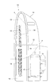
パラレルフロー型熱交換器20を一体型空気調和機に搭載した状況を図2に示す。図2の一体型空気調和機10は図7の一体型空気調和機10の構造を基本的に踏襲している。図5と共通する構成要素には図7で用いた符号をそのまま付し、説明は省略する。
筐体11内に取り付けられたパラレルフロー型熱交換器20は、上部熱交換部40が室内循環風路18に配置され、下部熱交換部41が放熱風路19に配置されている。
コンパクトな構成のパラレルフロー型熱交換器20を搭載することから、一体型空気調和機10そのものも小型・軽量化することができる。また、蒸発器と凝縮器を別々に設置するのにくらべ、設置作業が容易になり、作業時間も短縮される。
冷房運転時には、蒸発器として機能している上部熱交換部40の外面に空気中の水分が結露して、凝縮水が生じる。凝縮水は重力で滴下または流下し、凝縮器として機能している下部熱交換部41を濡らす。これにより、下部熱交換部41の凝縮効果が一層高められる。
パラレルフロー型熱交換器20の第2実施形態を図3に示す。第2実施形態が第1実施形態と異なる点は、ヘッダパイプ21、22の中の内部の仕切板30、31が断熱仕切板30HI、31HIに置き換えられていることである。断熱仕切板30HI、31HIは熱的分離部HI形成の一翼を担い、熱的分離を一層確実なものとする。
図3では、2枚の仕切板を両者間に空間が生じるように配置して断熱仕切板30HI、31HIを形成している。断熱仕切板30HI、31HIはアルミニウム製なので、一枚板だと熱移動が生じ易いが、2枚の板を両者間に空間が生じるように配置することにより十分な断熱性を持たせることができる。2枚の板の間の空間は、何らかの気体を封入してもよく、真空状態としてもよい。
断熱仕切板30HI、31HIは上記以外の手法でも形成できる。例えば、板の厚みを増したり、板の材料を断熱性のものに変更したりするなどして断熱仕切板30HI、31HIを形成することとしてもよい。
パラレルフロー型熱交換器20の第3実施形態を図4に示す。第3実施形態では、下部熱交換部41の下部冷媒出入口36が冷媒配管42で上部熱交換部40の下部冷媒出入口33に接続されている。
第3実施形態のパラレルフロー型熱交換器20では、下部熱交換部41において、仕切板37より上に位置する偏平チューブ23の数と、仕切板37と仕切板39の間の高さに位置する偏平チューブ23の数は等しく、仕切板39と仕切板38の間の高さに位置する偏平チューブ23の数はそれより少なく、仕切板38より下に位置する偏平チューブ23の数はさらに少ない。
冷房運転時には、図示しない圧縮機から吐出された高温高圧の冷媒が上部冷媒出入口35から下部熱交換部41に入る。下部熱交換部41に入った冷媒は、仕切板37より上に位置する偏平チューブ23を通ってヘッダパイプ21に向かう。ヘッダパイプ21に入った冷媒は折り返し、仕切板37と仕切板39の間の偏平チューブ23を通ってヘッダパイプ22に向かう。ヘッダパイプ22に入った冷媒は再び折り返し、仕切板39と仕切板38の間の偏平チューブ23を通ってヘッダパイプ21に向かう。ヘッダパイプ21に入った冷媒は再び折り返し、仕切板38より下の偏平チューブ23を通ってヘッダパイプ22に向かい、下部冷媒出入口36から流出する。
上部冷媒出入口35から下部熱交換部41に流入した高温高圧の冷媒は、下部熱交換部41の内部を上から下へとジグザグに流れる過程で、下部熱交換部41を通過する空気に放熱し、凝縮する。下部熱交換部41の下部冷媒出入口36を出た冷媒は減圧膨張装置43を経た後、下部冷媒出入口33から上部熱交換部40に入る。上部熱交換部40に入った冷媒は膨張し、上部熱交換部40を通過する空気から熱を奪う。その後冷媒は上部冷媒出入口32から出て前記図示しない圧縮機に戻る。
凝縮器として機能する下部熱交換部41において、冷媒は上位の偏平チューブ23から下位の偏平チューブ23へと流れる。上から下への動きは液体の冷媒にとって自然な動きであり、効率良く熱交換を行うことができる。
パラレルフロー型熱交換器20の第4実施形態を図5に示す。第4実施形態では、下部熱交換部41の下部冷媒出入口36が冷媒配管42で上部熱交換部40の上部冷媒出入口32に接続されている。
冷房運転時には、上部冷媒出入口32から上部熱交換部40に入った冷媒は、上位の偏平チューブ23から下位の偏平チューブ23へと流れつつ膨張し、上部熱交換部40を通過する空気から熱を奪う。その後冷媒は下部冷媒出入口33から出て前記図示しない圧縮機に戻る。
第3実施形態と第4実施形態においても、仕切板30、31を断熱仕切板30HI、31HIに置き換えることにより、熱的分離を一層確実なものとすることができる。
以上、本発明の実施形態につき説明したが、本発明の範囲はこれに限定されるものではなく、発明の主旨を逸脱しない範囲で種々の変更を加えて実施することができる。
本発明はサイドフロー方式パラレルフロー型熱交換器及びそれを搭載する一体型空気調和機に利用可能である。
10 一体型空気調和機
11 筐体
12 仕切板
13 冷房室
14 排熱室
17 圧縮機
18 室内循環風路
19 放熱風路
20 パラレルフロー型熱交換器
21、22 ヘッダパイプ
23 偏平チューブ
24 冷媒通路
25 フィン
27 上部群
28 下部群
30、31 仕切板
30HI、31HI 断熱仕切板
32、35 上部冷媒出入口
33、36 下部冷媒出入口
40 上部熱交換部
41 下部熱交換部
HI 熱的分離部
11 筐体
12 仕切板
13 冷房室
14 排熱室
17 圧縮機
18 室内循環風路
19 放熱風路
20 パラレルフロー型熱交換器
21、22 ヘッダパイプ
23 偏平チューブ
24 冷媒通路
25 フィン
27 上部群
28 下部群
30、31 仕切板
30HI、31HI 断熱仕切板
32、35 上部冷媒出入口
33、36 下部冷媒出入口
40 上部熱交換部
41 下部熱交換部
HI 熱的分離部
Claims (7)
- 以下の構成を備えるサイドフロー方式パラレルフロー型熱交換器:
間隔を置いて平行に配置された複数のヘッダパイプと、
前記複数のヘッダパイプの間に複数配置され、内部に設けられた冷媒通路が前記複数のヘッダパイプの内部に連通する偏平チューブと、
前記偏平チューブ同士の間に配置されたフィンとを備え、
前記複数の偏平チューブは当該熱交換器の上部に位置する上部群と当該熱交換器の下部に位置する下部群に二分され、
前記上部群の偏平チューブと、それに対応する前記複数のヘッダパイプの一部が上部熱交換部を構成し、
前記下部群の偏平チューブと、それに対応する前記複数のヘッダパイプの一部が下部熱交換部を構成する。 - 請求項1の熱交換器であって、以下の構成を備えるもの:
前記上部熱交換部と前記下部熱交換部の一方が蒸発器として機能し、他方が凝縮器として機能する。 - 請求項2の熱交換器であって、以下の構成を備えるもの:
前記上部熱交換部と前記下部熱交換部のうち、凝縮器として機能する側では、冷媒が上位の前記偏平チューブから下位の前記偏平チューブに流れる。 - 請求項1の熱交換器であって、以下の構成を備えるもの:
前記上部熱交換部と前記下部熱交換部の間に熱的分離部が形成される。 - 請求項4の熱交換器であって、以下の構成を備えるもの:
前記複数のヘッダパイプの内部に断熱仕切板が形成され、前記断熱仕切板が前記熱的分離部の一翼を担う。 - 以下の構成を備える一体型空気調和機:
当該空気調和機には請求項1から5のいずれかの熱交換器が搭載され、
当該空気調和機の筐体内には室内空気循環風路と放熱風路が形成され、
前記熱交換器の前記上部熱交換部は前記室内空気循環風路に配置され、
前記熱交換器の前記下部熱交換部は前記放熱風路に配置される。 - 請求項6の空気調和機であって、以下の構成を備えるもの:
前記上部熱交換器は蒸発器として機能し、前記下部熱交換部は凝縮器として機能する。
Priority Applications (2)
| Application Number | Priority Date | Filing Date | Title |
|---|---|---|---|
| CN2011800579038A CN103238037A (zh) | 2010-12-01 | 2011-11-17 | 热交换器和安装有热交换器的一体化空调机 |
| US13/883,648 US20130220584A1 (en) | 2010-12-01 | 2011-11-17 | Heat exchanger, and all-in-one air conditioner equipped therewith |
Applications Claiming Priority (2)
| Application Number | Priority Date | Filing Date | Title |
|---|---|---|---|
| JP2010-268228 | 2010-12-01 | ||
| JP2010268228A JP5618368B2 (ja) | 2010-12-01 | 2010-12-01 | 熱交換器及びそれを搭載した一体型空気調和機 |
Publications (1)
| Publication Number | Publication Date |
|---|---|
| WO2012073719A1 true WO2012073719A1 (ja) | 2012-06-07 |
Family
ID=46171663
Family Applications (1)
| Application Number | Title | Priority Date | Filing Date |
|---|---|---|---|
| PCT/JP2011/076572 Ceased WO2012073719A1 (ja) | 2010-12-01 | 2011-11-17 | 熱交換器及びそれを搭載した一体型空気調和機 |
Country Status (4)
| Country | Link |
|---|---|
| US (1) | US20130220584A1 (ja) |
| JP (1) | JP5618368B2 (ja) |
| CN (1) | CN103238037A (ja) |
| WO (1) | WO2012073719A1 (ja) |
Cited By (2)
| Publication number | Priority date | Publication date | Assignee | Title |
|---|---|---|---|---|
| WO2014016324A1 (fr) * | 2012-07-24 | 2014-01-30 | Valeo Systemes Thermiques | Echangeur thermique multi-fluides pour véhicules automobiles |
| JP2021008982A (ja) * | 2019-07-01 | 2021-01-28 | 東芝キヤリア株式会社 | 熱交換器および冷凍サイクル装置 |
Families Citing this family (16)
| Publication number | Priority date | Publication date | Assignee | Title |
|---|---|---|---|---|
| JP6139093B2 (ja) * | 2012-10-23 | 2017-05-31 | シャープ株式会社 | パラレルフロー型熱交換器 |
| EP2881693A1 (de) * | 2013-12-05 | 2015-06-10 | Miele & Cie. KG | Wärmetauscher für Haushaltsgeräte wie beispielsweise Wäschetrockner, Geschirrspüler oder Waschtrockner |
| CN103900399A (zh) * | 2014-03-21 | 2014-07-02 | 广东芬尼克兹节能设备有限公司 | 多功能一体化的集成换热器 |
| KR101566747B1 (ko) * | 2014-04-14 | 2015-11-13 | 현대자동차 주식회사 | 차량용 히트펌프 시스템 |
| KR101540071B1 (ko) * | 2015-01-27 | 2015-07-29 | (주)삼원산업사 | 공조용 응축기 제조 방법 |
| KR20160117937A (ko) * | 2015-04-01 | 2016-10-11 | 삼성전자주식회사 | 냉장고 및 이에 적용되는 열교환기 |
| JP6589235B2 (ja) * | 2015-06-26 | 2019-10-16 | 本田技研工業株式会社 | 空気調和装置 |
| JP6537928B2 (ja) * | 2015-08-19 | 2019-07-03 | 三菱重工サーマルシステムズ株式会社 | 熱交換器及びヒートポンプシステム |
| DE102016214116A1 (de) * | 2016-08-01 | 2018-02-01 | Volkswagen Aktiengesellschaft | Klimatisierungsvorrichtung für ein Kraftfahrzeug |
| US10222130B2 (en) * | 2016-08-08 | 2019-03-05 | Caterpillar Inc. | Work machine heat exchanger |
| US10712095B2 (en) * | 2018-02-14 | 2020-07-14 | Lennox Industries Inc. | Heat exchanger construction |
| DE102018129988A1 (de) | 2018-07-09 | 2020-01-09 | Hanon Systems | Kompaktwärmeübertragereinheit und Klimaanlagenmodul, insbesondere für Elektrofahrzeuge |
| JP7081417B2 (ja) * | 2018-09-18 | 2022-06-07 | 株式会社デンソー | 熱交換器 |
| CN110422309B (zh) * | 2019-07-02 | 2021-10-08 | 哈尔滨工程大学 | 应用于吊舱推进器推进电机的开式冷却系统及控制方法 |
| KR102728390B1 (ko) * | 2020-05-08 | 2024-11-12 | 한온시스템 주식회사 | 열교환기 및 이를 이용하는 히트펌프 시스템 |
| CN112414164A (zh) * | 2020-12-07 | 2021-02-26 | 惠州汉旭五金塑胶科技有限公司 | 多流道式高效散热水冷排 |
Citations (3)
| Publication number | Priority date | Publication date | Assignee | Title |
|---|---|---|---|---|
| JP2003042597A (ja) * | 2001-07-27 | 2003-02-13 | Denso Corp | 一体型熱交換器 |
| JP2008267730A (ja) * | 2007-04-23 | 2008-11-06 | Denso Corp | 複式熱交換器 |
| JP2010054111A (ja) * | 2008-08-28 | 2010-03-11 | Sharp Corp | 一体型空気調和機 |
Family Cites Families (12)
| Publication number | Priority date | Publication date | Assignee | Title |
|---|---|---|---|---|
| US4651816A (en) * | 1986-03-19 | 1987-03-24 | Modine Manufacturing Company | Heat exchanger module for a vehicle or the like |
| US5765393A (en) * | 1997-05-28 | 1998-06-16 | White Consolidated Industries, Inc. | Capillary tube incorporated into last pass of condenser |
| JPH1194483A (ja) * | 1997-09-25 | 1999-04-09 | Zexel:Kk | 熱交換器 |
| FR2786259B1 (fr) * | 1998-11-20 | 2001-02-02 | Valeo Thermique Moteur Sa | Echangeur de chaleur combine, en particulier pour vehicule automobile |
| JP3969099B2 (ja) * | 2002-01-18 | 2007-08-29 | 株式会社デンソー | 車両用空調装置 |
| JP2005106431A (ja) * | 2003-10-01 | 2005-04-21 | Denso Corp | 熱交換器モジュール |
| US7096932B2 (en) * | 2003-12-22 | 2006-08-29 | Modine Manufacturing Company | Multi-fluid heat exchanger and method of making same |
| JP4779641B2 (ja) * | 2005-12-26 | 2011-09-28 | 株式会社デンソー | 複合型熱交換器 |
| KR101202258B1 (ko) * | 2006-02-13 | 2012-11-16 | 한라공조주식회사 | 일체형 열교환기 |
| KR101222509B1 (ko) * | 2006-04-13 | 2013-01-15 | 한라공조주식회사 | 자동차용 열교환기 |
| CN100526759C (zh) * | 2007-08-16 | 2009-08-12 | 青岛大学 | 复合式吸附制冷装置 |
| JP5540816B2 (ja) * | 2010-03-26 | 2014-07-02 | 株式会社デンソー | 蒸発器ユニット |
-
2010
- 2010-12-01 JP JP2010268228A patent/JP5618368B2/ja not_active Expired - Fee Related
-
2011
- 2011-11-17 WO PCT/JP2011/076572 patent/WO2012073719A1/ja not_active Ceased
- 2011-11-17 US US13/883,648 patent/US20130220584A1/en not_active Abandoned
- 2011-11-17 CN CN2011800579038A patent/CN103238037A/zh active Pending
Patent Citations (3)
| Publication number | Priority date | Publication date | Assignee | Title |
|---|---|---|---|---|
| JP2003042597A (ja) * | 2001-07-27 | 2003-02-13 | Denso Corp | 一体型熱交換器 |
| JP2008267730A (ja) * | 2007-04-23 | 2008-11-06 | Denso Corp | 複式熱交換器 |
| JP2010054111A (ja) * | 2008-08-28 | 2010-03-11 | Sharp Corp | 一体型空気調和機 |
Cited By (4)
| Publication number | Priority date | Publication date | Assignee | Title |
|---|---|---|---|---|
| WO2014016324A1 (fr) * | 2012-07-24 | 2014-01-30 | Valeo Systemes Thermiques | Echangeur thermique multi-fluides pour véhicules automobiles |
| FR2993965A1 (fr) * | 2012-07-24 | 2014-01-31 | Valeo Systemes Thermiques | Echangeur thermique multi-fluides pour vehicules automobiles |
| JP2021008982A (ja) * | 2019-07-01 | 2021-01-28 | 東芝キヤリア株式会社 | 熱交換器および冷凍サイクル装置 |
| JP7296264B2 (ja) | 2019-07-01 | 2023-06-22 | 東芝キヤリア株式会社 | 熱交換器および冷凍サイクル装置 |
Also Published As
| Publication number | Publication date |
|---|---|
| US20130220584A1 (en) | 2013-08-29 |
| CN103238037A (zh) | 2013-08-07 |
| JP2012117751A (ja) | 2012-06-21 |
| JP5618368B2 (ja) | 2014-11-05 |
Similar Documents
| Publication | Publication Date | Title |
|---|---|---|
| JP5618368B2 (ja) | 熱交換器及びそれを搭載した一体型空気調和機 | |
| JP4827882B2 (ja) | 熱交換器モジュール、熱交換器、室内ユニット及び空調冷凍装置、並びに熱交換器の製造方法 | |
| CN104620069B (zh) | 并流式热交换器和安装有该并流式热交换器的空气调节机 | |
| JP5385588B2 (ja) | 空気調和機の室外機 | |
| JP5079857B2 (ja) | 空気調和機の室内機 | |
| JP2010107103A (ja) | 空気調和機の室外機 | |
| JP6740057B2 (ja) | 冷蔵庫 | |
| JP2013002774A (ja) | パラレルフロー型熱交換器及びそれを搭載した空気調和機 | |
| JP6987227B2 (ja) | 熱交換器及び冷凍サイクル装置 | |
| WO2018040037A1 (zh) | 微通道换热器及风冷冰箱 | |
| WO2018040036A1 (zh) | 微通道换热器及风冷冰箱 | |
| JP4995308B2 (ja) | 空気調和機の室内機 | |
| JP5516387B2 (ja) | 冷凍装置の室外ユニット | |
| JP6139093B2 (ja) | パラレルフロー型熱交換器 | |
| JP2006284133A (ja) | 熱交換器 | |
| JP5940895B2 (ja) | パラレルフロー型熱交換器及びそれを搭載した空気調和機 | |
| JP5763436B2 (ja) | パラレルフロー型熱交換器及びそれを搭載した空気調和機 | |
| JP2011047600A (ja) | 熱交換器及びそれを搭載した空気調和機 | |
| US20080066487A1 (en) | Condenser and radiator of air conditioning refrigeration system | |
| WO2017130975A1 (ja) | 熱交換器 | |
| JP2012042128A (ja) | 熱交換器及びそれを搭載した空気調和機 | |
| JP2012037099A (ja) | 空気調和機の室内機 | |
| JP2013234815A (ja) | 空気調和機 | |
| JPWO2020065697A1 (ja) | 熱交換器、該熱交換器を備えた空気調和機、及び該熱交換器を備えた冷蔵庫 | |
| JP2013228133A (ja) | 空気調和機 |
Legal Events
| Date | Code | Title | Description |
|---|---|---|---|
| 121 | Ep: the epo has been informed by wipo that ep was designated in this application |
Ref document number: 11844772 Country of ref document: EP Kind code of ref document: A1 |
|
| WWE | Wipo information: entry into national phase |
Ref document number: 13883648 Country of ref document: US |
|
| NENP | Non-entry into the national phase |
Ref country code: DE |
|
| 122 | Ep: pct application non-entry in european phase |
Ref document number: 11844772 Country of ref document: EP Kind code of ref document: A1 |