WO2012070652A1 - 面照明装置およびバックライト装置 - Google Patents
面照明装置およびバックライト装置 Download PDFInfo
- Publication number
- WO2012070652A1 WO2012070652A1 PCT/JP2011/077217 JP2011077217W WO2012070652A1 WO 2012070652 A1 WO2012070652 A1 WO 2012070652A1 JP 2011077217 W JP2011077217 W JP 2011077217W WO 2012070652 A1 WO2012070652 A1 WO 2012070652A1
- Authority
- WO
- WIPO (PCT)
- Prior art keywords
- light
- coherent light
- optical element
- recording medium
- hologram recording
- Prior art date
Links
- 230000001427 coherent effect Effects 0.000 claims abstract description 178
- 230000003287 optical effect Effects 0.000 claims abstract description 110
- 238000005286 illumination Methods 0.000 claims abstract description 66
- 238000000605 extraction Methods 0.000 claims abstract description 41
- 230000001902 propagating effect Effects 0.000 claims description 3
- 230000000644 propagated effect Effects 0.000 claims description 2
- 239000000463 material Substances 0.000 description 24
- 238000000034 method Methods 0.000 description 21
- 230000008569 process Effects 0.000 description 12
- 230000005540 biological transmission Effects 0.000 description 9
- 238000009792 diffusion process Methods 0.000 description 8
- 238000010586 diagram Methods 0.000 description 6
- 239000003086 colorant Substances 0.000 description 5
- 230000004048 modification Effects 0.000 description 5
- 238000012986 modification Methods 0.000 description 5
- 230000000694 effects Effects 0.000 description 3
- GGCZERPQGJTIQP-UHFFFAOYSA-N sodium;9,10-dioxoanthracene-2-sulfonic acid Chemical compound [Na+].C1=CC=C2C(=O)C3=CC(S(=O)(=O)O)=CC=C3C(=O)C2=C1 GGCZERPQGJTIQP-UHFFFAOYSA-N 0.000 description 3
- 241000282412 Homo Species 0.000 description 2
- 230000001678 irradiating effect Effects 0.000 description 2
- 239000004973 liquid crystal related substance Substances 0.000 description 2
- 206010034972 Photosensitivity reaction Diseases 0.000 description 1
- 230000002159 abnormal effect Effects 0.000 description 1
- NIXOWILDQLNWCW-UHFFFAOYSA-N acrylic acid group Chemical group C(C=C)(=O)O NIXOWILDQLNWCW-UHFFFAOYSA-N 0.000 description 1
- 230000009471 action Effects 0.000 description 1
- 238000007792 addition Methods 0.000 description 1
- 230000002411 adverse Effects 0.000 description 1
- 238000003491 array Methods 0.000 description 1
- 230000008859 change Effects 0.000 description 1
- 239000002131 composite material Substances 0.000 description 1
- 230000007547 defect Effects 0.000 description 1
- 238000012217 deletion Methods 0.000 description 1
- 230000037430 deletion Effects 0.000 description 1
- 238000006073 displacement reaction Methods 0.000 description 1
- 239000000284 extract Substances 0.000 description 1
- 230000004907 flux Effects 0.000 description 1
- 239000011521 glass Substances 0.000 description 1
- 239000011022 opal Substances 0.000 description 1
- 239000002245 particle Substances 0.000 description 1
- 230000036211 photosensitivity Effects 0.000 description 1
- 230000010287 polarization Effects 0.000 description 1
- 238000012805 post-processing Methods 0.000 description 1
- 238000007493 shaping process Methods 0.000 description 1
- 238000001228 spectrum Methods 0.000 description 1
- 238000012360 testing method Methods 0.000 description 1
Images


Classifications
-
- G—PHYSICS
- G02—OPTICS
- G02B—OPTICAL ELEMENTS, SYSTEMS OR APPARATUS
- G02B6/00—Light guides; Structural details of arrangements comprising light guides and other optical elements, e.g. couplings
- G02B6/0001—Light guides; Structural details of arrangements comprising light guides and other optical elements, e.g. couplings specially adapted for lighting devices or systems
- G02B6/0011—Light guides; Structural details of arrangements comprising light guides and other optical elements, e.g. couplings specially adapted for lighting devices or systems the light guides being planar or of plate-like form
- G02B6/0013—Means for improving the coupling-in of light from the light source into the light guide
- G02B6/0023—Means for improving the coupling-in of light from the light source into the light guide provided by one optical element, or plurality thereof, placed between the light guide and the light source, or around the light source
-
- G—PHYSICS
- G02—OPTICS
- G02B—OPTICAL ELEMENTS, SYSTEMS OR APPARATUS
- G02B6/00—Light guides; Structural details of arrangements comprising light guides and other optical elements, e.g. couplings
- G02B6/0001—Light guides; Structural details of arrangements comprising light guides and other optical elements, e.g. couplings specially adapted for lighting devices or systems
- G02B6/0011—Light guides; Structural details of arrangements comprising light guides and other optical elements, e.g. couplings specially adapted for lighting devices or systems the light guides being planar or of plate-like form
- G02B6/0013—Means for improving the coupling-in of light from the light source into the light guide
-
- F—MECHANICAL ENGINEERING; LIGHTING; HEATING; WEAPONS; BLASTING
- F21—LIGHTING
- F21S—NON-PORTABLE LIGHTING DEVICES; SYSTEMS THEREOF; VEHICLE LIGHTING DEVICES SPECIALLY ADAPTED FOR VEHICLE EXTERIORS
- F21S2/00—Systems of lighting devices, not provided for in main groups F21S4/00 - F21S10/00 or F21S19/00, e.g. of modular construction
- F21S2/005—Systems of lighting devices, not provided for in main groups F21S4/00 - F21S10/00 or F21S19/00, e.g. of modular construction of modular construction
-
- F—MECHANICAL ENGINEERING; LIGHTING; HEATING; WEAPONS; BLASTING
- F21—LIGHTING
- F21K—NON-ELECTRIC LIGHT SOURCES USING LUMINESCENCE; LIGHT SOURCES USING ELECTROCHEMILUMINESCENCE; LIGHT SOURCES USING CHARGES OF COMBUSTIBLE MATERIAL; LIGHT SOURCES USING SEMICONDUCTOR DEVICES AS LIGHT-GENERATING ELEMENTS; LIGHT SOURCES NOT OTHERWISE PROVIDED FOR
- F21K2/00—Non-electric light sources using luminescence; Light sources using electrochemiluminescence
-
- G—PHYSICS
- G02—OPTICS
- G02B—OPTICAL ELEMENTS, SYSTEMS OR APPARATUS
- G02B27/00—Optical systems or apparatus not provided for by any of the groups G02B1/00 - G02B26/00, G02B30/00
- G02B27/48—Laser speckle optics
-
- G—PHYSICS
- G02—OPTICS
- G02B—OPTICAL ELEMENTS, SYSTEMS OR APPARATUS
- G02B5/00—Optical elements other than lenses
- G02B5/32—Holograms used as optical elements
-
- G—PHYSICS
- G02—OPTICS
- G02B—OPTICAL ELEMENTS, SYSTEMS OR APPARATUS
- G02B6/00—Light guides; Structural details of arrangements comprising light guides and other optical elements, e.g. couplings
- G02B6/0001—Light guides; Structural details of arrangements comprising light guides and other optical elements, e.g. couplings specially adapted for lighting devices or systems
- G02B6/0011—Light guides; Structural details of arrangements comprising light guides and other optical elements, e.g. couplings specially adapted for lighting devices or systems the light guides being planar or of plate-like form
- G02B6/0013—Means for improving the coupling-in of light from the light source into the light guide
- G02B6/0023—Means for improving the coupling-in of light from the light source into the light guide provided by one optical element, or plurality thereof, placed between the light guide and the light source, or around the light source
- G02B6/003—Lens or lenticular sheet or layer
-
- G—PHYSICS
- G02—OPTICS
- G02B—OPTICAL ELEMENTS, SYSTEMS OR APPARATUS
- G02B6/00—Light guides; Structural details of arrangements comprising light guides and other optical elements, e.g. couplings
- G02B6/0001—Light guides; Structural details of arrangements comprising light guides and other optical elements, e.g. couplings specially adapted for lighting devices or systems
- G02B6/0011—Light guides; Structural details of arrangements comprising light guides and other optical elements, e.g. couplings specially adapted for lighting devices or systems the light guides being planar or of plate-like form
- G02B6/0013—Means for improving the coupling-in of light from the light source into the light guide
- G02B6/0023—Means for improving the coupling-in of light from the light source into the light guide provided by one optical element, or plurality thereof, placed between the light guide and the light source, or around the light source
- G02B6/0031—Reflecting element, sheet or layer
-
- G—PHYSICS
- G02—OPTICS
- G02B—OPTICAL ELEMENTS, SYSTEMS OR APPARATUS
- G02B6/00—Light guides; Structural details of arrangements comprising light guides and other optical elements, e.g. couplings
- G02B6/0001—Light guides; Structural details of arrangements comprising light guides and other optical elements, e.g. couplings specially adapted for lighting devices or systems
- G02B6/0011—Light guides; Structural details of arrangements comprising light guides and other optical elements, e.g. couplings specially adapted for lighting devices or systems the light guides being planar or of plate-like form
- G02B6/0066—Light guides; Structural details of arrangements comprising light guides and other optical elements, e.g. couplings specially adapted for lighting devices or systems the light guides being planar or of plate-like form characterised by the light source being coupled to the light guide
-
- G—PHYSICS
- G02—OPTICS
- G02F—OPTICAL DEVICES OR ARRANGEMENTS FOR THE CONTROL OF LIGHT BY MODIFICATION OF THE OPTICAL PROPERTIES OF THE MEDIA OF THE ELEMENTS INVOLVED THEREIN; NON-LINEAR OPTICS; FREQUENCY-CHANGING OF LIGHT; OPTICAL LOGIC ELEMENTS; OPTICAL ANALOGUE/DIGITAL CONVERTERS
- G02F1/00—Devices or arrangements for the control of the intensity, colour, phase, polarisation or direction of light arriving from an independent light source, e.g. switching, gating or modulating; Non-linear optics
- G02F1/01—Devices or arrangements for the control of the intensity, colour, phase, polarisation or direction of light arriving from an independent light source, e.g. switching, gating or modulating; Non-linear optics for the control of the intensity, phase, polarisation or colour
- G02F1/13—Devices or arrangements for the control of the intensity, colour, phase, polarisation or direction of light arriving from an independent light source, e.g. switching, gating or modulating; Non-linear optics for the control of the intensity, phase, polarisation or colour based on liquid crystals, e.g. single liquid crystal display cells
- G02F1/133—Constructional arrangements; Operation of liquid crystal cells; Circuit arrangements
- G02F1/1333—Constructional arrangements; Manufacturing methods
- G02F1/1335—Structural association of cells with optical devices, e.g. polarisers or reflectors
-
- G—PHYSICS
- G03—PHOTOGRAPHY; CINEMATOGRAPHY; ANALOGOUS TECHNIQUES USING WAVES OTHER THAN OPTICAL WAVES; ELECTROGRAPHY; HOLOGRAPHY
- G03H—HOLOGRAPHIC PROCESSES OR APPARATUS
- G03H1/00—Holographic processes or apparatus using light, infrared or ultraviolet waves for obtaining holograms or for obtaining an image from them; Details peculiar thereto
- G03H1/32—Systems for obtaining speckle elimination
-
- F—MECHANICAL ENGINEERING; LIGHTING; HEATING; WEAPONS; BLASTING
- F21—LIGHTING
- F21Y—INDEXING SCHEME ASSOCIATED WITH SUBCLASSES F21K, F21L, F21S and F21V, RELATING TO THE FORM OR THE KIND OF THE LIGHT SOURCES OR OF THE COLOUR OF THE LIGHT EMITTED
- F21Y2115/00—Light-generating elements of semiconductor light sources
- F21Y2115/10—Light-emitting diodes [LED]
-
- G—PHYSICS
- G02—OPTICS
- G02B—OPTICAL ELEMENTS, SYSTEMS OR APPARATUS
- G02B6/00—Light guides; Structural details of arrangements comprising light guides and other optical elements, e.g. couplings
- G02B6/0001—Light guides; Structural details of arrangements comprising light guides and other optical elements, e.g. couplings specially adapted for lighting devices or systems
- G02B6/0011—Light guides; Structural details of arrangements comprising light guides and other optical elements, e.g. couplings specially adapted for lighting devices or systems the light guides being planar or of plate-like form
- G02B6/0013—Means for improving the coupling-in of light from the light source into the light guide
- G02B6/0023—Means for improving the coupling-in of light from the light source into the light guide provided by one optical element, or plurality thereof, placed between the light guide and the light source, or around the light source
- G02B6/0025—Diffusing sheet or layer; Prismatic sheet or layer
-
- G—PHYSICS
- G02—OPTICS
- G02F—OPTICAL DEVICES OR ARRANGEMENTS FOR THE CONTROL OF LIGHT BY MODIFICATION OF THE OPTICAL PROPERTIES OF THE MEDIA OF THE ELEMENTS INVOLVED THEREIN; NON-LINEAR OPTICS; FREQUENCY-CHANGING OF LIGHT; OPTICAL LOGIC ELEMENTS; OPTICAL ANALOGUE/DIGITAL CONVERTERS
- G02F1/00—Devices or arrangements for the control of the intensity, colour, phase, polarisation or direction of light arriving from an independent light source, e.g. switching, gating or modulating; Non-linear optics
- G02F1/01—Devices or arrangements for the control of the intensity, colour, phase, polarisation or direction of light arriving from an independent light source, e.g. switching, gating or modulating; Non-linear optics for the control of the intensity, phase, polarisation or colour
- G02F1/13—Devices or arrangements for the control of the intensity, colour, phase, polarisation or direction of light arriving from an independent light source, e.g. switching, gating or modulating; Non-linear optics for the control of the intensity, phase, polarisation or colour based on liquid crystals, e.g. single liquid crystal display cells
- G02F1/133—Constructional arrangements; Operation of liquid crystal cells; Circuit arrangements
- G02F1/1333—Constructional arrangements; Manufacturing methods
- G02F1/1335—Structural association of cells with optical devices, e.g. polarisers or reflectors
- G02F1/1336—Illuminating devices
- G02F1/133615—Edge-illuminating devices, i.e. illuminating from the side
-
- G—PHYSICS
- G03—PHOTOGRAPHY; CINEMATOGRAPHY; ANALOGOUS TECHNIQUES USING WAVES OTHER THAN OPTICAL WAVES; ELECTROGRAPHY; HOLOGRAPHY
- G03H—HOLOGRAPHIC PROCESSES OR APPARATUS
- G03H1/00—Holographic processes or apparatus using light, infrared or ultraviolet waves for obtaining holograms or for obtaining an image from them; Details peculiar thereto
- G03H1/22—Processes or apparatus for obtaining an optical image from holograms
- G03H1/2286—Particular reconstruction light ; Beam properties
- G03H2001/2292—Using scanning means
Definitions
- the present invention relates to a surface illumination device and a backlight device using a light source that emits coherent light.
- a backlight device used for a liquid crystal panel or the like a method is known in which light is incident from the edge of a light guide plate, total reflection is repeated between two opposing surfaces, and light is extracted by a diffusing element or the like.
- this type of backlight device in addition to those using a cold cathode tube as a light source, there are devices using an LED as a light source in recent years.
- the laser beam is excellent in straightness, it is considered that the light incident efficiency to the light guide plate can be improved as compared with the LED.
- speckles are generated due to the high coherence.
- a speckle is a speckled pattern that appears when a scattering surface is irradiated with laser light or other coherent light. When it appears on a screen, it is observed as speckled brightness irregularities (brightness irregularities). It becomes a factor having a physiological adverse effect on the person.
- speckles occur when coherent light is used is that coherent light reflected by each part of a scattering reflection surface such as a screen interferes with each other because of its extremely high coherence. . For example, in Speckle Phenomena in Optics, Joseph W. Goodman, Roberts & Co., 2006, a detailed theoretical study of speckle generation is made.
- speckles are produced by irradiating a scattering plate with laser light, guiding scattered light obtained therefrom to an optical modulator, and rotating the scattering plate by a motor.
- a technique for reducing the above is disclosed.
- Speckle is a problem not only in backlight devices, but also in various devices that incorporate lighting devices that illuminate coherent light in the illuminated area.
- Coherent light as represented by laser light, has excellent straightness and can be irradiated as very high energy density light. Therefore, it is preferable that the light path of the coherent light is designed as an illuminating device actually developed corresponding to the characteristics of the coherent light.
- an object of the present invention is to provide a surface illumination device and a backlight device that can prevent speckles from being noticeable and can effectively suppress the occurrence of uneven brightness in a predetermined area. To do.
- an optical element capable of diffusing coherent light from each point to the entire corresponding region in a predetermined region;
- An irradiation device that irradiates the optical element with the coherent light so that coherent light scans the surface of the optical element;
- a light guide plate that propagates coherent light reflected by the surface of the optical element or transmitted through the optical element, and takes out the coherent light to the outside.
- the irradiation device changes the traveling direction of coherent light, and scans the coherent light on the surface of the optical element,
- the light guide plate transmits coherent light to the outside while propagating the coherent light between a first end face on which coherent light from the optical element is incident and a second end face disposed opposite to the first end face.
- a light extraction part The surface illumination device is provided in which the predetermined region is provided inside the light extraction unit, along the first end surface, or along the second end surface.
- a surface illumination device and a backlight device that can prevent speckles from becoming conspicuous and can effectively suppress the occurrence of uneven brightness in a predetermined area.
- FIG. The figure which shows schematic structure of the surface illumination apparatus which concerns on embodiment of this invention.
- the figure which shows schematic structure of the surface illumination apparatus which concerns on the modification of FIG. The figure explaining the principle of operation of the illuminating device 40 of FIG.
- FIG. The figure which shows the result of having measured the speckle contrast with the case where it does not use the case where the hologram recording medium 55 is used.
- the surface illumination device according to an embodiment of the present invention can be applied as, for example, a backlight illumination device incorporated in a liquid crystal panel or the like, but is not necessarily limited to application to a backlight illumination device, and has a surface of a predetermined size. It can also be used as a surface illumination device that performs illumination.
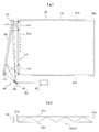
- FIG. 1 is a diagram showing a schematic configuration of a surface illumination device according to an embodiment of the present invention
- FIG. 1 (a) is a plan view
- FIG. 1 (b) is a sectional view of FIG. 1 (a).
- the surface illumination device shown in FIG. 1 includes an optical element 50, an irradiation device 60, and a light guide plate 30.
- an illumination device 40 a combination of the optical element 50 and the irradiation device 60
- a combination of the light guide plate 30 and the illumination device 40 is referred to as a surface illumination device.
- the irradiation device 60 irradiates the optical element 50 with coherent light so that the coherent light scans the surface of the optical element 50.
- the irradiation device 60 includes a laser light source 61 that emits coherent light, and a scanning device 65 that scans the surface of the optical element 50 with the coherent light emitted from the laser light source 61.
- the optical element 50 has a hologram recording medium 55 that can reproduce an image of a scattering plate in an illuminated area (predetermined area) LZ. Details of the hologram recording medium 55 will be described later.
- a hologram recording medium 55 On the hologram recording medium 55, a plurality of recording areas r1 to rn are provided. Coherent light reflected by the scanning device 65 at different reflection angle ranges is incident on each of the plurality of recording regions r1 to rn. The coherent light scans over the corresponding recording area. Interference fringes are formed in each of the recording regions r1 to rn. When coherent light is incident, the coherent light diffracted by the interference fringes is emitted as divergent light (diffused light).
- coherent light in the corresponding reflection angle range from the scanning device 65 is incident on each of the recording regions r1 to rn on the hologram recording medium 55 to scan the recording region.
- the recording areas r 1 to rn on the hologram recording medium 55 are arranged in close contact with one end surface of the light guide plate 31.
- a light extraction portion 32 is provided on at least a part of the light guide plate 31.
- the light extraction unit 32 is provided with an illuminated area LZ that is illuminated by coherent light from the optical element 50.
- the coherent light incident on each point in each of the recording areas r1 to rn on the hologram recording medium 55 becomes diffused light and forms line images LZ1 to LZn in the corresponding areas in the illuminated area LZ.
- line images LZ1 to LZn are formed in n corresponding areas in the illuminated area LZ, respectively.
- the illuminated area LZ is provided inside the light extraction unit 31, along the first end surface 31 a closest to the optical element 50, or along the second end surface 31 b farthest from the optical element 50.
- the light extraction unit 31 includes a first end surface 31a on which coherent light from the optical element 50 is incident, and a second end surface 31b disposed to face the first end surface 31a. And third and fourth end faces 31c and 31d connected to the first and second end faces 31a and 31b.
- the light extraction unit 31 propagates the coherent light incident from the first end surface 31a toward the second end surface 31b while reflecting the light from the third and fourth end surfaces 31c and 31d, and is in the middle of the propagation.
- light is gradually extracted from the third end face 31c or the fourth end face 31d to the outside.
- it functions as a surface illumination device that irradiates light of uniform brightness from the entire third end surface 31c or fourth end surface 31d.
- Diffused light from each of the recording regions r1 to rn on the hologram recording medium 55 reaches the first end surface 31a of the light extraction unit 31 while being totally reflected by the two opposing surfaces of the light guide plate 30. Thereby, the diffused light from each recording medium 55 can be incident on the first end face 31a with almost no leakage.
- the light guide plate 30 has, for example, a structure in which an acrylic plate is sandwiched between a diffusion sheet and a reflection sheet, and reflection dots are printed with white ink on the reflection sheet.
- the diffusion sheet corresponding to the third end surface 31c is a light extraction surface
- the reflection sheet corresponding to the fourth end surface 31d is a reflection surface.
- FIG. 1 shows an example in which the hologram recording medium 55 of the optical element 50 is closely arranged on the light guide plate 30, the two may be arranged apart from each other.
- FIG. 2 is a modification of FIG. 1, and is a diagram showing a surface illumination device in which the hologram recording medium 55 and the light guide plate 30 are spaced apart, FIG. 2 (a) is a plan view, and FIG. 2 (b) is a plan view. It is sectional drawing.
- the light guide plate 30 is the remaining surface except for the first end surface 31a that is the incident surface of the diffused light from the optical element 50, the light extraction surface (third end surface 31c), and the fourth end surface 31d facing it.
- Three end faces (second, fifth and sixth end faces 31b, 31e, 31f) are mirror surfaces.
- the diffused light from each of the recording regions r1 to rn on the hologram recording medium 55 is directly reflected on the light guide plate 30 from the first end face 31a side without being reflected somewhere, and on the second end face 31b side. And propagates while being reflected by the third and fourth end faces 31c and 31d.
- the second, fifth and sixth end faces 31b, 31e, 31f are mirror surfaces, so that they are totally reflected and light extraction surfaces. Light can be efficiently extracted from the (third end face).
- the second, fifth, and sixth end faces 31b, 31e, and 31f do not necessarily have to be mirror surfaces, and only some of the end faces may be mirror surfaces.
- the hologram recording medium 55 and the light guide plate 30 are separated from each other, so that the diffused light from the hologram recording medium 55 is easily incident on the light guide plate 30. It is desirable to make structural measures on the side. For example, as an example, it is conceivable to increase the thickness of the light guide plate 30 on the diffused light incident surface side so that diffused light is easily incident.
- the illuminated region LZ is located inside the light extraction unit 31, along the first end surface 31 a closest to the optical element 50, or It is provided along the second end face 31 b farthest from the optical element 50.
- At least one of the second, fifth, and sixth end surfaces 31b, 31e, and 31f may be a mirror surface.
- FIG. 3 is a diagram for explaining the operating principle of the lighting device 40.
- FIG. 3 only some components in the lighting device 40 are illustrated for the sake of simplicity of explanation.
- the basic operation principle of the illumination device 40 will be described with reference to FIG.
- the hologram recording medium 55 constituting the optical element 50 can receive the coherent light emitted from the irradiation device 60 as the reproduction illumination light La, and can diffract the coherent light with high efficiency.
- the hologram recording medium 55 reproduces the image 5 of the scattering plate 6 in the illuminated area LZ by diffracting coherent light incident on each position, in other words, each minute area that should also be called each point. Can be done.
- the irradiation device 60 is configured so that the coherent light irradiated to the hologram recording medium 55 scans the hologram recording medium 55 by the scanning device 65. Therefore, at a certain moment, the irradiation device 60 irradiates a minute area on the surface of the hologram recording medium 55 with coherent light.
- the coherent light emitted from the irradiation device 60 and scanned on the hologram recording medium 55 satisfies the diffraction condition of the hologram recording medium 55 at each position on the hologram recording medium 55 (each minute region, the same applies hereinafter).
- the incident light is incident at a proper incident angle.
- the coherent light incident on each position of the hologram recording medium 55 from the irradiation device 60 is diffracted by the hologram recording medium 55 and illuminates a predetermined region that overlaps at least partly.
- the coherent light incident on each position of the hologram recording medium 55 from the irradiation device 60 is diffracted by the hologram recording medium 55 to illuminate the same illuminated region LZ. .
- the coherent light that has entered the arbitrary positions in the recording regions r1 to rn of the hologram recording medium 55 from the irradiation device 60 respectively corresponds to the corresponding region in the illuminated region LZ.
- the image 5 of the scattering plate 6 is reproduced so as to overlap the region.
- the coherent light incident on the hologram recording medium 55 from any position in the recording areas r1 to rn from the irradiation device 60 is diffused (expanded) by the optical element 50 and corresponds to the illuminated area LZ. Incident into the region, line images LZ1 to LZn are formed.
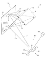
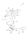
- FIG. 4 is a diagram for explaining how the image of the scattering plate is formed on the hologram recording medium 55 as interference fringes.
- the scattering plate 6 is a reference member that scatters light, and a specific form of the reference member is not limited.
- the hologram recording medium 55 is manufactured using the scattered light from the actual scattering plate 6 as the object light Lo.
- FIG. 4 shows a state in which the hologram photosensitive material 58 having photosensitivity that forms the hologram recording medium 55 is exposed to the reference light Lr and the object light Lo, which are coherent light beams having coherence with each other. Has been.
- the reference light Lr for example, laser light from a laser light source 61 that oscillates laser light in a specific wavelength range is used.
- the reference light Lr passes through the condensing element 7 made of a lens and enters the hologram photosensitive material 58.
- the laser light for forming the reference light Lr is incident on the condensing element 7 as a parallel light beam parallel to the optical axis of the condensing element 7.
- the reference light Lr passes through the condensing element 7, so that it is shaped (converted) into a convergent light beam from the parallel light beam so far, and is incident on the hologram photosensitive material 58.
- the focal position FP of the convergent light beam Lr is at a position past the hologram photosensitive material 58. That is, the hologram photosensitive material 58 is disposed between the light condensing element 7 and the focal position FP of the convergent light beam Lr condensed by the light condensing element 7.
- the object light Lo is incident on the hologram photosensitive material 58 as scattered light from a scattering plate 6 made of, for example, opal glass.
- the hologram recording medium 55 to be manufactured is a reflection type, and the object light Lo is incident on the hologram photosensitive material 58 from the surface opposite to the reference light Lr.
- the object light Lo is premised on having coherency with the reference light Lr. Therefore, for example, the laser light oscillated from the same laser light source 61 can be divided, and one of the divided light can be used as the reference light Lr and the other can be used as the object light Lo.
- a parallel light beam parallel to the normal direction to the plate surface of the scattering plate 6 is incident on the scattering plate 6 and scattered, and the scattered light transmitted through the scattering plate 6 is the object light Lo.
- the light enters the hologram photosensitive material 58.
- the object light Lo from the scattering plate 6 is incident on the hologram photosensitive material 58 with a substantially uniform light amount distribution. Is possible.
- the object light Lo is incident on each position of the hologram photosensitive material 58 with a substantially uniform light amount from the entire area of the exit surface 6 a of the scattering plate 6. It becomes easy. In such a case, the light incident on each position of the obtained hologram recording medium 55 reproduces the image 5 of the scattering plate 6 with the same brightness, and the reproduced image of the scattering plate 6. It can be realized that 5 is observed with approximately uniform brightness.
- the hologram recording material 58 when the hologram recording material 58 is exposed to the reference light Lr and the object light Lo, an interference fringe formed by the interference of the reference light Lr and the object light Lo is generated. It is recorded on the hologram recording material 58 as a pattern (in the case of a volume hologram, for example, a refractive index modulation pattern). Thereafter, appropriate post-processing corresponding to the type of the hologram recording material 58 is performed, and the hologram recording material 55 is obtained.
- a pattern in the case of a volume hologram, for example, a refractive index modulation pattern
- the hologram recording medium 55 of the present embodiment has a plurality of recording areas r1 to rn, interference fringes are formed by the method shown in FIG. 4 for each recording area.
- FIG. 5 is a view for explaining a state in which the image of the scattering plate is reproduced using the interference fringes formed on the hologram recording medium 55 obtained through the exposure process of FIG.
- the hologram recording medium 55 formed of the hologram photosensitive material 58 of FIG. 4 is light having the same wavelength as the laser beam used in the exposure process, and the optical path of the reference light Lr in the exposure process The light traveling in the opposite direction satisfies the Bragg condition. That is, as shown in FIG. 5, the reference point SP positioned with respect to the hologram recording medium 55 so as to have the same positional relationship as the relative position of the focal point FP with respect to the hologram photosensitive material 58 during the exposure process (see FIG. 4).
- the divergent light beam that diverges from the light beam and has the same wavelength as the reference light Lr during the exposure process is diffracted by the hologram recording medium 55 as the reproduction illumination light La, and is relative to the hologram photosensitive material 58 during the exposure process.
- the reproduced image 5 of the scattering plate 6 is generated at a specific position with respect to the hologram recording medium 55 that has the same positional relationship as the position (see FIG. 4).
- the reproduction light (light obtained by diffracting the reproduction illumination light La by the hologram recording medium 55) Lb that generates the reproduction image 5 of the scattering plate 6 travels from the scattering plate 6 toward the hologram photosensitive material 58 during the exposure process.
- Each point of the image 5 of the scattering plate 6 is reproduced as light traveling in the opposite direction along the optical path of the object light Lo that has been emitted.
- the scattered light Lo emitted from each position of the exit surface 6 a of the scattering plate 6 during the exposure process is diffused so as to be incident on almost the entire region of the hologram photosensitive material 58. Yes (spread).
- the object light Lo from the entire area of the exit surface 6 a of the scattering plate 6 is incident on each position on the hologram photosensitive material 58, and as a result, information on the entire exit surface 6 a is placed on each position of the hologram recording medium 55. Each is recorded. For this reason, each light that forms a divergent light beam from the reference point SP functioning as the reproduction illumination light La shown in FIG. 5 is incident on each position of the hologram recording medium 55 independently and has the same contour.
- the image 5 of the scattering plate 6 can be reproduced at the same position (illuminated area LZ).
- the irradiation apparatus 60 includes a laser light source 61 that generates coherent light, and a scanning device 65 that changes the traveling direction of the coherent light from the laser light source 61. .
- the laser light source 61 emits visible light, for example.
- a plurality of laser light sources 61 that emit laser beams of different wavelength bands may be used.
- the laser light from each laser light source 61 irradiates the same point on the scanning device 65. Thereby, the hologram recording medium 55 is illuminated with the reproduction illumination light in which the illumination colors of the laser light sources 61 are mixed.
- the hologram recording medium 55 is provided with n recording areas r1 to rn corresponding to the n line images LZ1 to LZn formed in the illuminated area LZ. Coherent light having a corresponding reflection angle range from the scanning device 65 is incident on each of the recording regions r1 to rn.
- the reference light Lr and the object light Lo are irradiated for each recording area to form interference fringes in the corresponding recording area according to the principle of FIG. do it.
- the recording areas r1 to rn are not necessarily arranged in close contact, and there may be a gap between them.
- the coherent light incident on the gap is not used for generating the line images LZ1 to LZn, but there is no problem in practical use.
- interference fringes may be formed such that adjacent recording areas overlap.
- the line images LZ1 to LZn are not necessarily arranged in close contact with each other and may have a gap. Even if there are some gaps, there is no practical problem as long as uniform surface illumination is possible due to the characteristics of the light guide plate 30. For the same reason, as long as uniform surface illumination is possible, adjacent line images may be formed to overlap each other.
- the laser light source may be a monochromatic laser light source or may be configured using a plurality of laser light sources having different emission colors (for example, red, green, and blue).
- each laser light source is arranged so that coherent light from each laser light source is irradiated to one point on the scanning device 65, it corresponds to the incident angle of the coherent light from each laser light source.
- the light is reflected at the reflection angle, is incident on the hologram recording medium 55, is diffracted separately from the hologram recording medium 55, and is superimposed on the illuminated region LZ to become a composite color (for example, white).
- a separate scanning device 65 may be provided for each laser light source.
- the type of laser light source provided in the irradiation device 60 is not particularly limited.
- the scanning device 65 changes the traveling direction of the coherent light with time, and directs it in various directions so that the traveling direction of the coherent light is not constant. As a result, the coherent light whose traveling direction is changed by the scanning device 65 scans the incident surface of the hologram recording medium 55 of the optical element 50.
- any recording area can be set depending on the incident direction of the coherent light from the scanning device 65. Coherent light is incident.
- the scanning device 65 includes a reflection device 66 having a reflection surface 66a that can be rotated about one axis RA1.
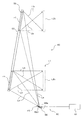
- FIG. 6 is a diagram for explaining the scanning path of the scanning device 65.
- the reflection device 66 includes a mirror device having a mirror as a reflection surface 66a that can be rotated about one axis RA1.
- This mirror device 66 changes the traveling direction of coherent light from the laser light source 61 by changing the orientation of the mirror 66a.
- the mirror device 66 generally receives coherent light from the laser light source 61 at the reference point SP.
- the coherent light whose traveling direction is finally adjusted by the mirror device 66 is incident on the hologram recording medium 55 of the optical element 50 as reproduction illumination light La (see FIG. 5) that can form one light beam diverging from the reference point SP. obtain.
- the coherent light from the irradiation device 60 scans on the hologram recording medium 55, and the image of the scattering plate 6 in which the coherent light incident on each position on the hologram recording medium 55 has the same contour. 5 is reproduced at the same position (illuminated area LZ).
- the reflection device 66 is configured to rotate the mirror 66a along one axis RA1.
- the rotation axis RA ⁇ b> 1 of the mirror 66 a has an XY coordinate system defined on the plate surface of the hologram recording medium 55 (that is, the XY plane is parallel to the plate surface of the hologram recording medium 55. It extends parallel to the Y axis of the (XY coordinate system). Then, since the mirror 66a rotates around the axis line RA1 parallel to the Y axis of the XY coordinate system defined on the plate surface of the hologram recording medium 55, the coherent light from the irradiation device 60 is applied to the optical element 50.
- the incident point IP reciprocates in a direction parallel to the X axis of the XY coordinate system defined on the plate surface of the hologram recording medium 55. That is, in the example shown in FIG. 6, the irradiation device 60 irradiates the optical element 50 with coherent light so that the coherent light scans on the hologram recording medium 55 along a linear path.
- the scanning device 65 configured by the mirror device 66 or the like is a member that can rotate at least around the axis A1, and is configured by using, for example, MEMS.
- the scanning device 65 periodically rotates, but in applications such as a backlight device that is directly observed by humans, it is 1/30 seconds per cycle, or more coherent light depending on the type of screen to be displayed. If the scanning can be carried out, the rotation frequency is not particularly limited.
- the hologram recording material 58 may shrink when the hologram recording medium 55 is produced.
- the traveling direction of the light incident on the hologram recording medium 55 of the optical element 50 does not take exactly the same path as the one light beam included in the divergent light beam from the reference point SP, it is illuminated.
- the image 5 can be reproduced in the region LZ.
- the mirror (reflection surface) 66a of the mirror device 66 constituting the scanning device 65 is inevitably deviated from the rotation axis RA1. Therefore, when the mirror 66a is rotated around the rotation axis RA1 that does not pass through the reference point SP, the light incident on the hologram recording medium 55 may not be a single light beam that forms a divergent light beam from the reference point SP. is there.
- the image 5 can be substantially reproduced by being superimposed on the illuminated region LZ by coherent light from the irradiation device 60 having the illustrated configuration.
- the scanning device 65 does not necessarily need to be a member that reflects the coherent light, and may be scanned on the optical element 50 by causing the coherent light to be refracted or diffracted instead of being reflected. (Operational effect of this embodiment)
- the irradiation device 60 irradiates the optical element 50 with coherent light so that the coherent light sequentially scans the n recording regions r1 to rn in the hologram recording medium 55 of the optical element 50.
- coherent light having a specific wavelength traveling along a certain direction is generated by the laser light source 61, and this coherent light is irradiated to the scanning device 65, and the traveling direction thereof is varied. More specifically, each coherent light travels toward the hologram recording medium 55 at a reflection angle corresponding to the incident angle from the laser light source 61.
- the scanning device 65 makes each position on the hologram recording medium 55 incident coherent light of a corresponding specific wavelength at an incident angle that satisfies the Bragg condition at the position.
- the coherent light incident on each position is reproduced by the diffraction due to the interference fringes recorded on the hologram recording medium 55 so as to overlap the entire area in the corresponding area of the illuminated area LZ to reproduce the image 5 of the scattering plate 6.
- the coherent light incident on each position of the hologram recording medium 55 from the irradiation device 60 is diffused (expanded) by the optical element 50 and is incident on the entire corresponding area of the illuminated area LZ.
- the coherent light incident at an arbitrary position in the recording area r1 is superimposed on the entire area in the corresponding area in the illuminated area LZ to reproduce the line image LZ1.
- the irradiation device 60 illuminates the illuminated area LZ with coherent light.
- the laser light source 61 has a plurality of laser light sources 61 that emit light in different colors
- the image 5 of the scattering plate 6 is reproduced in each color in the illuminated region LZ. Therefore, when these laser light sources 61 emit light at the same time, the illuminated area LZ is illuminated with white in which three colors are mixed.
- the incident position of the coherent light from the scanning device 65 on the hologram recording medium 55 moves with time within each position by driving the scanning device 65.
- the illuminated area LZ is provided in the vicinity of the first end face 31a of the light extraction unit 31, for example. Since the first end surface 31a is provided at a position closest to the optical element 50 in the light extraction unit 31, the illumination light of the illuminated region LZ is transmitted from the third and fourth end surfaces 31c and 31d of the light extraction unit 31. The light propagates in the direction of the second end face 31b while being reflected.
- One of the third and fourth end surfaces 31c and 31d (for example, the third end surface 31c) is a light extraction surface that reflects the illumination light of the illuminated region LZ and extracts a part of the illumination light to the outside. is there. Thereby, uniform illumination light can be extracted from the entire third end face 31c.
- the illuminated area LZ is not necessarily provided in the vicinity of the first end face 31a closest to the optical element 50, and may be provided in the light extraction portion 31 or farthest from the optical element 50. You may provide in the vicinity of the 2nd end surface 31b.
- the illuminated region LZ is provided in the vicinity of the second end surface 31b, the coherent light incident on any position in the recording regions r1 to rn of the hologram recording medium 55 becomes diffused light, The entire region within the corresponding region of the illuminated region LZ is propagated from the first end surface 31a to the inside of the light extraction portion 31 and directly propagates with or without reflection at the third and fourth end surfaces 31c and 31d. The image of the scattering plate overlaid on is reproduced.
- the hologram recording medium 55 is provided with a plurality of recording regions r1 to rn, each formed with interference fringes, and a plurality of line images LZ1 to LZn are formed in the illuminated region LZ.
- the first and second end faces 31a and 31b of the light extraction portion 31 have a large width (for example, several tens of cm or more).
- the widths of the first and second end faces 31a and 31b are large, the width of the illuminated area LZ is also large, but the diffusion angle obtained by the hologram recording medium 55 is not so large. There is a possibility that the entire illuminated area LZ cannot be illuminated.
- the hologram recording medium 55 is provided with a plurality of recording areas r1 to rn.
- the hologram recording medium 55 does not have to be provided with a plurality of recording areas r1 to rn. In this case, the coherent light irradiated at an arbitrary point on the hologram recording medium 55 is superimposed on the entire illuminated area LZ to reproduce a line image.
- the mode refers to speckle patterns that are uncorrelated with each other.
- coherent light is projected from different directions onto the same screen from a plurality of laser light sources 61
- coherent light from the same laser light source 61 is projected onto the screen from different directions every unit time, the number of times the incident direction of the coherent light has changed during the time that cannot be resolved by the human eye Will exist.
- the interference patterns of light are overlapped uncorrelatedly and averaged, and as a result, speckles observed by the observer's eyes become inconspicuous.
- the irradiation device 60 described above irradiates the optical element 50 with coherent light so that the coherent light scans on the hologram recording medium 55. Further, the coherent light incident on the recording device r1 to rn in the hologram recording medium 55 from the irradiation device 60 illuminates the entire region in the corresponding region of the same illuminated region LZ. The illumination directions of the coherent light that illuminates the illumination area LZ are different from each other. Since the position on the hologram recording medium 55 where the coherent light enters changes with time, the incident direction of the coherent light to the illuminated region LZ also changes with time.
- coherent light continuously scans on the hologram recording medium 55.
- the incident direction of coherent light incident on the illuminated area LZ from the irradiation device 60 via the optical element 50 also changes continuously.
- the pattern of speckles generated on the illuminated area LZ also changes greatly, and is uncorrelated.
- a speckle pattern is superimposed.
- the frequency of scanning devices 65 such as MEMS mirrors and polygon mirrors that are commercially available is usually several hundred Hz or higher, and scanning devices 65 that reach tens of thousands of Hz are not uncommon.
- the incident direction of coherent light changes temporally at each position of the illuminated region LZ, and this change is a speed that cannot be resolved by the human eye. It is. Accordingly, if a screen is arranged in the illuminated area LZ, speckles generated corresponding to each scattering pattern are superimposed and averaged and observed by the observer, so that the image displayed on the screen Speckle can be made very inconspicuous for an observer who observes the above.
- the illuminated region LZ is disposed in the vicinity of the light extraction unit 31. Thereby, speckles are not noticeable in the illumination light extracted from the light extraction unit 31.
- speckles observed by humans include not only speckles on the light extraction unit 31 side due to scattering of coherent light in the light extraction unit 31 but also before entering the light extraction unit 31. Speckle on the side of the optical element 50 due to scattering of coherent light in can also occur. The speckle pattern generated on the optical element 50 side can be taken out from the light extraction unit 31 to be recognized by an observer.
- the coherent light continuously scans on the hologram recording medium 55, and the coherent light incident on any position of each of the recording regions r1 to rn in the hologram recording medium 55 is Each of the entire areas in the corresponding area of the illuminated area LZ is illuminated.
- the hologram recording medium 55 forms a new wavefront that is separate from the wavefront used to form the speckle pattern, and is complex and uniform to the outside via the illuminated region LZ and the light extraction unit 31. It is taken out. By forming a new wavefront on the hologram recording medium 55, the speckle pattern generated on the optical element 50 side becomes invisible.
- the scanning device 65 is used to scan the coherent light on the hologram recording medium 55, and the coherent light irradiated from the recording regions r 1 to rn in the hologram recording medium 55 is used.
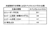
- Speckle Phenomena in Optics, Joseph W. Goodman, Roberts & Co., 2006 proposed a method that uses a value called speckle contrast (unit%) as a parameter indicating the degree of speckle generated on the screen. ing.
- speckle contrast is defined as a value obtained by dividing the standard deviation of the actual luminance variation on the screen divided by the average luminance value when displaying a test pattern image that should have a uniform luminance distribution. Amount. The larger the speckle contrast value is, the larger the speckle occurrence level on the screen is, which indicates that the spot-like luminance unevenness pattern is more prominently presented to the observer.
- FIG. 7 is a diagram showing the result of measuring speckle contrast with and without using the hologram recording medium 55 described above.
- FIG. 7A shows a case in which a laser beam is directly applied to the illuminated region LZ without using the scanning device 65 and the optical element 50
- FIG. 7C shows the case where a relief diffusion plate is used as the optical element 50
- FIG. 7D shows a case where a single color LED is used instead of the laser light source 61 as the irradiation device 60 and the emitted light of the single color LED is directly irradiated onto the illuminated area LZ.
- the problem of speckle generation is a problem inherent to practical use when a coherent light source such as a laser beam is used, and is a problem that need not be considered in an apparatus using a non-coherent light source such as an LED.
- the speckle contrast is superior to the case of using the monochromatic LED according to the present embodiment, but it is considered that the light diffusing element 21 is not used for illumination of the monochromatic LED. From the above, it can be said that the surface illumination device according to the present embodiment was able to sufficiently cope with speckle defects.
- the optical element 50 for making speckles inconspicuous can also function as an optical member for shaping and adjusting the beam form of coherent light emitted from the irradiation device 60. Therefore, the optical system can be reduced in size and simplified.
- the coherent light incident on specific positions in the recording areas r1 to rn of the hologram recording medium 55 is scattered in the respective colors in the entire area of the corresponding area in the illuminated area LZ. Image 5 is generated. For this reason, all the light diffracted by the hologram recording medium 55 can be used for illumination, and the use efficiency of the light from the laser light source 61 is excellent.
- a part of the coherent light from the irradiation device 60 passes through the hologram recording medium 55 without being diffracted by the hologram recording medium 55. Such light is called zero order light. If zero-order light enters the illuminated area LZ, an abnormal area (a dotted area, a linear area, or a planar area) in which the brightness (luminance) increases sharply compared with the surrounding area is the illuminated area LZ. Will occur within.
- the reflection type hologram recording medium 55 (hereinafter referred to as reflection type holo)
- the illuminated region LZ and the light extraction unit 31 are not arranged in the direction in which the 0th order light travels, and therefore the 0th order light can be relatively easily transmitted.
- transmission type holo a transmission type hologram recording medium 55
- the distance from the transmission type holo to the first end face is short, and each recording area of the transmission type holo Since r1 to rn are aligned in a uniaxial direction, it is difficult to take a configuration that avoids zero-order light. Therefore, in the case of a transmission type holo, it is desired to increase the diffraction efficiency as much as possible and suppress the influence of zero-order light as much as possible.
- the reflection type holo has higher wavelength selectivity than the transmission type holo. That is, the reflection type holo can diffract coherent light having a desired wavelength only by a desired layer even if interference fringes corresponding to different wavelengths are laminated.
- the reflection type holo is also excellent in that it is easy to remove the influence of zero-order light.
- the transmission type holo has a wide diffractable spectrum and a wide tolerance of the laser light source 61.
- interference fringes corresponding to different wavelengths are laminated, coherent light of a desired wavelength is generated even in layers other than the desired layer. It will be diffracted. Therefore, in general, it is difficult to make the transmission type holo a laminated structure.
- the reflection type hologram recording medium 55 is disposed obliquely with respect to the first end surface 31 a of the light extraction unit 31.
- the hologram recording medium 55 is disposed substantially in parallel with the first end face 31a, and the coherent light reflected by the scanning device 65 is reflected again to reconstruct the hologram recording medium 55.
- a reflecting member (not shown) for guiding light to the surface may be newly provided.
- the scanning device 65 is an example of the uniaxial rotation type mirror device 66 that changes the traveling direction of the coherent light by reflection, the scanning device 65 is not limited thereto. As shown in FIG. 8, the scanning device 65 has a second rotation in which the mirror (reflection surface 66a) of the mirror device 66 intersects not only the first rotation axis RA1 but also the first rotation axis RA1. It may be rotatable about the axis RA2. In the example shown in FIG.
- the second rotation axis RA2 of the mirror 66a is a first rotation axis RA1 extending in parallel with the Y axis of the XY coordinate system defined on the plate surface of the hologram recording medium 55.
- the incident point IP of the coherent light from the irradiation device 60 to the optical element 50 is the plate of the hologram recording medium 55. It is possible to move in a two-dimensional direction on the surface. For this reason, as shown in FIG. 8 as an example, the incident point IP of the coherent light to the optical element 50 can be moved on the circumference.
- the scanning device 65 may include two or more mirror devices 66.
- the mirror 66a of the mirror device 66 can be rotated only about a single axis, the incident point IP of the coherent light from the irradiation device 60 to the optical element 50 is expressed by the hologram recording medium 55. It can be moved in a two-dimensional direction on the plate surface.
- mirror device 66a included in the scanning device 65 includes a MEMS mirror, a polygon mirror, and the like.
- the scanning device 65 may include a device other than the reflection device (for example, the mirror device 66 described above) that changes the traveling direction of the coherent light by reflection.
- the scanning device 65 may include a refractive prism, a lens, and the like.
- the scanning device 65 is not essential, and the light source 61 of the irradiation device 60 is configured to be displaceable (movable, swinging, rotating) with respect to the optical element 50, and the light source 61 is displaced by the displacement of the light source 61 with respect to the optical element 50.
- the coherent light irradiated from the above may be scanned on the hologram recording medium 55.
- the light source 61 of the irradiation device 60 has been described on the premise that the light source 61 oscillates a laser beam shaped as a linear light beam, but is not limited thereto.
- the coherent light irradiated to each position of the optical element 50 is shaped by the optical element 50 into a light beam that enters the entire illuminated area LZ. Therefore, there is no inconvenience even if the coherent light irradiated from the light source 61 of the irradiation device 60 to the optical element 50 is not accurately shaped. For this reason, the coherent light generated from the light source 61 may be diverging light.
- the cross-sectional shape of the coherent light generated from the light source 61 may not be a circle but an ellipse or the like.
- the transverse mode of the coherent light generated from the light source 61 may be a multimode.
- the coherent light is incident on a region having a certain area instead of a point when entering the hologram recording medium 55 of the optical element 50.
- the light diffracted by the hologram recording medium 55 and incident on each position of the illuminated area LZ is multiplexed in angle.
- coherent light is incident on each position of the illuminated area LZ from a certain angle range. Speckle can be made more inconspicuous by such multiplexing of angles.
- the scanning device 65 may further include a condensing lens 67 disposed on the downstream side of the mirror device 66 along the optical path of the coherent light.
- the light from the mirror device 66 that travels along the optical path of the light beam constituting the divergent light beam becomes light that travels in a certain direction by the condenser lens 67.
- the irradiation device 60 causes the coherent light to be incident on the optical element 50 so as to follow the optical path of the light beam constituting the parallel light flux.
- a parallel light beam is used as the reference light Lr instead of the above-described convergent light beam.
- Such a hologram recording medium 55 can be produced and duplicated more easily.
- optical element 50 In the embodiment described above, an example in which the optical element 50 includes the reflective volume hologram 55 using a photopolymer has been described, but the present invention is not limited thereto. Further, the optical element 50 may include a volume hologram that is recorded using a photosensitive medium including a silver salt material. Furthermore, the optical element 50 may include a transmissive volume hologram recording medium 55 or a relief (embossed) hologram recording medium 55.
- a relief (embossed) hologram is recorded with hologram interference fringes due to the uneven structure on the surface.
- scattering due to the uneven structure on the surface may become a new speckle generation factor.
- the volume type hologram is preferable.
- the hologram interference fringe is recorded as a refractive index modulation pattern (refractive index distribution) inside the medium, it is not affected by scattering due to the uneven structure on the surface.
- the hologram recording medium 55 is preferably a volume hologram using a photopolymer.
- a so-called Fresnel type hologram recording medium 55 is produced.
- a Fourier transform type hologram recording medium 55 obtained by performing recording using a lens is produced. It doesn't matter. However, when the Fourier transform type hologram recording medium 55 is used, a lens may also be used during image reproduction.
- the striped pattern (refractive index modulation pattern or concave / convex pattern) to be formed on the hologram recording medium 55 does not use the actual object light Lo and reference light Lr, but the planned wavelength and incident direction of the reproduction illumination light La. In addition, it may be designed using a computer based on the shape and position of the image to be reproduced.
- the hologram recording medium 55 obtained in this way is also called a computer-generated hologram.
- the hologram recording medium 55 as a computer-generated hologram corresponds to the coherent light in each wavelength range.
- the coherent light in each wavelength region may be diffracted in the corresponding region to reproduce an image.
- the optical element 50 includes the hologram recording medium 55 that expands the coherent light irradiated to each position and illuminates the entire illuminated area LZ using the expanded coherent light.
- the optical element 50 changes the traveling direction of the coherent light irradiated to each position and diffuses instead of the hologram recording medium 55 or in addition to the hologram recording medium 55 so that the entire area to be illuminated LZ is coherent light.
- the irradiating device 60 scans the lens array with the coherent light so as to irradiate the optical element 50 with the coherent light.
- the irradiation device 60 and the optical element 50 By configuring the irradiation device 60 and the optical element 50 so that the traveling direction of the coherent light incident on the position is changed by the lens array to illuminate the illuminated area LZ, speckles are effectively inconspicuous. Can be made.
- the irradiation device 60 is configured to be able to scan the coherent light in the one-dimensional direction on the optical element 50, and the hologram recording medium 55 (or lens array) of the optical element 50 is irradiated to each position.
- the coherent light is configured to diffuse (spread and diverge) in a two-dimensional direction, whereby the illumination device 40 illuminates the two-dimensional illuminated area LZ.
- the present invention is not limited to such an example.
- the irradiation device 60 is configured to be able to scan the coherent light on the optical element 50 in a two-dimensional direction
- the hologram recording medium 55 (or lens array) of the optical element 50 is configured to diffuse (spread and diverge) the coherent light irradiated to each position in a two-dimensional direction.
- the illumination device 40 may illuminate the two-dimensional illuminated area LZ.
- the irradiation device 60 is configured to be able to scan the coherent light on the optical element 50 in a one-dimensional direction, and the hologram recording medium 55 (or lens array) of the optical element 50 is used. Is configured to diffuse (spread and diverge) the coherent light irradiated to each position in a one-dimensional direction, so that the illumination device 40 illuminates the one-dimensional illuminated region LZ. It may be.
- the scanning direction of the coherent light by the irradiation device 60 and the diffusion direction (expansion direction) of the hologram recording medium 55 (or lens array) of the optical element 50 may be parallel to each other.
- the irradiation device 60 is configured to be able to scan the coherent light on the optical element 50 in a one-dimensional direction or a two-dimensional direction, and the hologram recording medium 55 (or lens array) of the optical element 50 is placed at each position.
- the irradiated coherent light may be configured to diffuse (spread and diverge) in a one-dimensional direction.
- the optical element 50 has a plurality of hologram recording media 55 (or lens arrays), and sequentially illuminates the illuminated area LZ corresponding to each hologram recording medium 55 (or lens array). By doing so, the illumination device 40 may illuminate a two-dimensional area.
- each illuminated area LZ may be sequentially illuminated at a speed as if it were illuminated simultaneously by the human eye, or it can be recognized that the illuminated area LZ is also illuminated sequentially by the human eye. It may be illuminated sequentially at such a slow speed. That is, the plurality of recording regions r1 to rn described above may be formed using one hologram recording medium 55, or a plurality of recording media may be formed using different hologram recording media 55, respectively. .
Landscapes
- Physics & Mathematics (AREA)
- General Physics & Mathematics (AREA)
- Optics & Photonics (AREA)
- Nonlinear Science (AREA)
- Engineering & Computer Science (AREA)
- Mathematical Physics (AREA)
- Chemical & Material Sciences (AREA)
- Crystallography & Structural Chemistry (AREA)
- General Engineering & Computer Science (AREA)
- Electromagnetism (AREA)
- Holo Graphy (AREA)
- Diffracting Gratings Or Hologram Optical Elements (AREA)
- Planar Illumination Modules (AREA)
- Liquid Crystal (AREA)
- Light Guides In General And Applications Therefor (AREA)
Abstract
Description
コヒーレント光が前記光学素子の表面を走査するように、前記光学素子に前記コヒーレント光を照射する照射装置と、
前記光学素子の表面で反射され、または前記光学素子を透過したコヒーレント光を伝搬させると共に、該コヒーレント光を外部に取り出す導光板と、を備え、
前記照射装置は、コヒーレント光の進行方向を変化させて、該コヒーレント光を前記光学素子の表面上で走査させるものであり、
前記導光板は、前記光学素子からのコヒーレント光を入射する第1の端面と前記第1の端面に対向配置される第2の端面との間で、コヒーレント光を伝搬させながら、コヒーレント光を外部に取り出す光取り出し部を有し、
前記所定の領域は、前記光取り出し部の内部に、または前記第1の端面に沿って、または前記第2の端面に沿って設けられることを特徴とする面照明装置が提供される。
(本実施形態の作用効果)
(本実施形態のその他の特徴)
照射装置60からのコヒーレント光の一部は、ホログラム記録媒体55で回折されることなく当該ホログラム記録媒体55を透過する。このような光は0次光と呼ばれる。0次光が被照明領域LZに入射してしまうと、周囲と比較して明るさ(輝度)が急激に上昇する異常領域(点状領域、線状領域、面状領域)が被照明領域LZ内に発生してしまう。
反射型ホロは、透過型ホロに比べて、波長選択性が高い。すなわち、反射型ホロは、異なる波長に対応した干渉縞を積層させても、所望の層のみで所望の波長のコヒーレント光を回折させることができる。また、0次光の影響を除去しやすい点でも、反射型ホロは優れている。
上述した形態では、照射装置60が、レーザ光源61と走査デバイス65とを有する例を説明した。走査デバイス65は、コヒーレント光の進行方向を反射によって変化させる一軸回動型のミラーデバイス66からなる例を示したが、これに限られない。走査デバイス65は、図8に示すように、ミラーデバイス66のミラー(反射面66a)が、第1の回動軸線RA1だけでなく、第1の回動軸線RA1と交差する第2の回動軸線RA2を中心としても回動可能となっていてもよい。図8に示された例では、ミラー66aの第2の回動軸線RA2は、ホログラム記録媒体55の板面上に定義されたXY座標系のY軸と平行に延びる第1回動軸線RA1と、直交している。そして、ミラー66aが、第1軸線RA1および第2軸線RA2の両方を中心として回動可能なため、照射装置60からのコヒーレント光の光学素子50への入射点IPは、ホログラム記録媒体55の板面上で二次元方向に移動可能となる。このため、一例として図8に示されているように、コヒーレント光の光学素子50への入射点IPが円周上を移動するようにすることもできる。
上述した形態において、光学素子50が、フォトポリマーを用いた反射型の体積型ホログラム55からなる例を示したが、これに限られない。また、光学素子50は、銀塩材料を含む感光媒体を利用して記録するタイプの体積型ホログラムを含んでもよい。さらに、光学素子50は、透過型の体積型ホログラム記録媒体55を含んでいてもよいし、レリーフ型(エンボス型)のホログラム記録媒体55を含んでいてもよい。
上述した形態において、照射装置60が光学素子50上でコヒーレント光を一次元方向に走査可能とするように構成され、且つ、光学素子50のホログラム記録媒体55(またはレンズアレイ)が各位置に照射されたコヒーレント光を二次元方向に拡散するよう(拡げるように、発散させるように)に構成され、これにより、照明装置40が二次元的な被照明領域LZを照明する例を示した。ただし、既に説明してきたように、このような例に限定されることはなく、例えば、照射装置60が光学素子50上でコヒーレント光を二次元方向に走査可能とするように構成され、且つ、光学素子50のホログラム記録媒体55(またはレンズアレイ)が各位置に照射されたコヒーレント光を二次元方向に拡散するよう(拡げるように、発散させるように)に構成され、これにより、図8に示したように、照明装置40が二次元的な被照明領域LZを照明してもよい。
Claims (11)
- 各点からのコヒーレント光を所定の領域内の対応領域の全域に対して拡散可能な光学素子と、
コヒーレント光が前記光学素子の表面を走査するように、前記光学素子に前記コヒーレント光を照射する照射装置と、
前記光学素子の表面で反射され、または前記光学素子を透過したコヒーレント光を伝搬させると共に、該コヒーレント光を外部に取り出す導光板と、を備え、
前記照射装置は、コヒーレント光の進行方向を変化させて、該コヒーレント光を前記光学素子の表面上で走査させるものであり、
前記導光板は、前記光学素子からのコヒーレント光を入射する第1の端面と前記第1の端面に対向配置される第2の端面との間で、コヒーレント光を伝搬させながら、コヒーレント光を外部に取り出す光取り出し部を有し、
前記所定の領域は、前記光取り出し部の内部に、または前記第1の端面に沿って、または前記第2の端面に沿って設けられることを特徴とする面照明装置。 - 前記光学素子は、前記導光板の一端面に接して配置され、
前記光学素子で拡散されたコヒーレント光は、前記導光板の一端面から入射して、前記導光板の対向する二面で全反射して、あるいは直接、前記光取り出し部の前記第1の端面に入射されることを特徴とする請求項1に記載の面照明装置。 - 前記光学素子は、前記導光板と離隔して配置され、
前記光学素子で拡散されたコヒーレント光の少なくとも一部が前記光取り出し部の前記第1の端面に入射されることを特徴とする請求項1に記載の面照明装置。 - 前記光学素子は、前記照射装置にてそれぞれ異なる角度範囲で進行方向が変更されたコヒーレント光が走査する複数の記録領域を有し、
前記所定の領域は、前記複数の記録領域のそれぞれに対応して設けられる複数の像再生領域を有し、
前記複数の記録領域のそれぞれは、前記複数の像再生領域の一つに対応づけられており、
前記複数の記録領域には、対応する前記像再生領域内の全域に参照部材の像を再生するための干渉縞がそれぞれ記録されることを特徴とする請求項1に記載の面照明装置。 - 前記導光板は、前記第1および第2の端面に連なる、対向配置される第3および第4の端面を有し、
前記第3または第4の端面から均一な輝度の光が照射されるように、前記複数の像再生領域は、隣接してまたは一部が重なり合うように配置されることを特徴とする請求項4に記載の面照明装置。 - 前記複数の記録領域は、一つのホログラム記録媒体を用いて形成されることを特徴とする請求項4に記載の面照明装置。
- 前記複数の記録領域は、それぞれ異なるホログラム記録媒体を用いて形成されることを特徴とする請求項4に記載の面照明装置。
- 前記導光板は、
前記第1および第2の端面に連なり、前記光取り出し部からの均一な輝度の光を照射する第3の端面と、
前記第3の端面に対向配置される第4の端面と、
前記第1~第4の端面に連なる第5および第6の端面と、を有し、
前記第2、第5および第6の端面の少なくとも一つは、前記第1の端面から入射されて伝搬してきたコヒーレント光を反射させるミラー面であることを特徴とする請求項1に記載の面照明装置。 - 前記光学素子は、前記第1の端面に配置された反射型のホログラム記録媒体であることを特徴とする請求項1に記載の面照明装置。
- 前記光学素子は、透過型のホログラム記録媒体であり、
前記照射装置は、
コヒーレント光を放射する光源と、
前記光源から放射された前記コヒーレント光の進行方向を変化させて、該コヒーレント光を前記光学素子の表面上で走査させる走査デバイスと、
前記走査デバイスにて進行方向が変更されたコヒーレント光の進行方向を再度変更させて、前記ホログラム記録媒体に導光する進行方向変更部材と、を有することを特徴とする請求項1に記載の面照明装置。 - 面照明装置を備えたバックライト装置であって、
前記面照明装置は、
各点からのコヒーレント光を所定の領域内の対応領域の全域に対して拡散可能な光学素子と、
コヒーレント光が前記光学素子の表面を走査するように、前記光学素子に前記コヒーレント光を照射する照射装置と、
前記光学素子の表面で反射され、または前記光学素子を透過したコヒーレント光を伝搬させると共に、該コヒーレント光を外部に取り出す導光板と、を備え、
前記照射装置は、コヒーレント光の進行方向を変化させて、該コヒーレント光を前記光学素子の表面上で走査させるものであり、
前記導光板は、前記光学素子からのコヒーレント光を入射する第1の端面と前記第1の端面に対向配置される第2の端面との間で、コヒーレント光を伝搬させながら、コヒーレント光を外部に取り出す光取り出し部を有し、
前記所定の領域は、前記光取り出し部の内部に、または前記第1の端面に沿って、または前記第2の端面に沿って設けられることを特徴とするバックライト装置。
Priority Applications (4)
| Application Number | Priority Date | Filing Date | Title |
|---|---|---|---|
| US13/989,465 US9470832B2 (en) | 2010-11-26 | 2011-11-25 | Plane illumination apparatus and backlight apparatus |
| EP11842892.9A EP2644965B1 (en) | 2010-11-26 | 2011-11-25 | Surface lighting device and backlight device |
| KR1020137013232A KR101811085B1 (ko) | 2010-11-26 | 2011-11-25 | 면 조명 장치 및 백라이트 장치 |
| CN201180056735.0A CN103221738B (zh) | 2010-11-26 | 2011-11-25 | 面照明装置及背光装置 |
Applications Claiming Priority (2)
| Application Number | Priority Date | Filing Date | Title |
|---|---|---|---|
| JP2010-263915 | 2010-11-26 | ||
| JP2010263915A JP6042051B2 (ja) | 2010-11-26 | 2010-11-26 | 面照明装置およびバックライト装置 |
Publications (1)
| Publication Number | Publication Date |
|---|---|
| WO2012070652A1 true WO2012070652A1 (ja) | 2012-05-31 |
Family
ID=46145989
Family Applications (1)
| Application Number | Title | Priority Date | Filing Date |
|---|---|---|---|
| PCT/JP2011/077217 WO2012070652A1 (ja) | 2010-11-26 | 2011-11-25 | 面照明装置およびバックライト装置 |
Country Status (7)
| Country | Link |
|---|---|
| US (1) | US9470832B2 (ja) |
| EP (1) | EP2644965B1 (ja) |
| JP (1) | JP6042051B2 (ja) |
| KR (1) | KR101811085B1 (ja) |
| CN (1) | CN103221738B (ja) |
| TW (1) | TWI518371B (ja) |
| WO (1) | WO2012070652A1 (ja) |
Cited By (1)
| Publication number | Priority date | Publication date | Assignee | Title |
|---|---|---|---|---|
| TWI581010B (zh) * | 2013-11-29 | 2017-05-01 | Lg顯示器股份有限公司 | 薄膜型控制視窗背光單元及使用該背光單元的薄平板型控制視窗顯示 器 |
Families Citing this family (5)
| Publication number | Priority date | Publication date | Assignee | Title |
|---|---|---|---|---|
| US9594240B2 (en) * | 2013-12-06 | 2017-03-14 | Samsung Electronics Co., Ltd. | Lighting apparatus, and optical inspection apparatus and optical microscope using the lighting apparatus |
| CN103775920B (zh) * | 2014-01-29 | 2015-12-30 | 京东方科技集团股份有限公司 | 一种扫描式背光模组及显示装置 |
| US20180172880A1 (en) * | 2015-06-16 | 2018-06-21 | 3M Innovative Properties Company | Light guide with anti reflection feature |
| KR102399100B1 (ko) * | 2017-06-16 | 2022-05-18 | 삼성디스플레이 주식회사 | 백라이트 유닛 및 이를 포함하는 표시 장치 |
| CN107229088B (zh) * | 2017-08-07 | 2020-11-03 | 京东方科技集团股份有限公司 | 光学微结构及光学微结构层的制作方法、导光组件及显示装置 |
Citations (5)
| Publication number | Priority date | Publication date | Assignee | Title |
|---|---|---|---|---|
| JPH06208089A (ja) | 1992-07-29 | 1994-07-26 | Texas Instr Inc <Ti> | コヒーレント光を用いる無スペックル・ディスプレイ装置 |
| JPH0894852A (ja) * | 1994-09-22 | 1996-04-12 | Japan Synthetic Rubber Co Ltd | 導光板 |
| JP2002169480A (ja) * | 2000-11-30 | 2002-06-14 | Fuji Photo Film Co Ltd | コリメート平面光源、それを用いた表示素子および表示装置 |
| WO2008108068A1 (ja) * | 2007-03-06 | 2008-09-12 | Panasonic Corporation | 光走査装置及びそれを用いた二次元画像表示装置 |
| WO2009147808A1 (ja) * | 2008-06-03 | 2009-12-10 | パナソニック株式会社 | 液晶バックライト及びこれを用いた液晶表示装置 |
Family Cites Families (11)
| Publication number | Priority date | Publication date | Assignee | Title |
|---|---|---|---|---|
| JPH10233915A (ja) * | 1997-02-17 | 1998-09-02 | Ricoh Co Ltd | 画像処理装置 |
| JP2003087514A (ja) | 2000-11-15 | 2003-03-20 | Nippon Sheet Glass Co Ltd | 画像読取り装置、その光源およびシェーディング補正装置 |
| WO2007058203A1 (ja) * | 2005-11-15 | 2007-05-24 | Matsushita Electric Industrial Co., Ltd. | 面状照明装置とそれを用いた液晶表示装置 |
| US8029179B2 (en) * | 2006-10-02 | 2011-10-04 | Panasonic Corporation | Planar illumination apparatus and liquid crystal display apparatus using the same |
| US8279514B2 (en) * | 2007-01-24 | 2012-10-02 | Osram Ag | Optoelectronic device |
| CN101373292A (zh) * | 2007-08-20 | 2009-02-25 | 中强光电股份有限公司 | 背光模块 |
| JP2009162825A (ja) | 2007-12-28 | 2009-07-23 | Seiko Epson Corp | 画像表示装置 |
| JP5386821B2 (ja) | 2007-12-28 | 2014-01-15 | セイコーエプソン株式会社 | 光源装置及びプロジェクタ |
| WO2009116224A1 (ja) * | 2008-03-19 | 2009-09-24 | パナソニック株式会社 | 面光源装置 |
| US7997735B2 (en) | 2008-03-27 | 2011-08-16 | Corning Incorporated | Systems and methods for speckle reduction |
| US8376585B2 (en) * | 2008-10-28 | 2013-02-19 | Raymond A. Noeth | Energy efficient illumination apparatus and method for illuminating surfaces |
-
2010
- 2010-11-26 JP JP2010263915A patent/JP6042051B2/ja active Active
-
2011
- 2011-11-25 EP EP11842892.9A patent/EP2644965B1/en active Active
- 2011-11-25 KR KR1020137013232A patent/KR101811085B1/ko active IP Right Grant
- 2011-11-25 US US13/989,465 patent/US9470832B2/en active Active
- 2011-11-25 WO PCT/JP2011/077217 patent/WO2012070652A1/ja active Application Filing
- 2011-11-25 CN CN201180056735.0A patent/CN103221738B/zh not_active Expired - Fee Related
- 2011-11-25 TW TW100143350A patent/TWI518371B/zh not_active IP Right Cessation
Patent Citations (5)
| Publication number | Priority date | Publication date | Assignee | Title |
|---|---|---|---|---|
| JPH06208089A (ja) | 1992-07-29 | 1994-07-26 | Texas Instr Inc <Ti> | コヒーレント光を用いる無スペックル・ディスプレイ装置 |
| JPH0894852A (ja) * | 1994-09-22 | 1996-04-12 | Japan Synthetic Rubber Co Ltd | 導光板 |
| JP2002169480A (ja) * | 2000-11-30 | 2002-06-14 | Fuji Photo Film Co Ltd | コリメート平面光源、それを用いた表示素子および表示装置 |
| WO2008108068A1 (ja) * | 2007-03-06 | 2008-09-12 | Panasonic Corporation | 光走査装置及びそれを用いた二次元画像表示装置 |
| WO2009147808A1 (ja) * | 2008-06-03 | 2009-12-10 | パナソニック株式会社 | 液晶バックライト及びこれを用いた液晶表示装置 |
Non-Patent Citations (3)
| Title |
|---|
| "Optics", 2006, JOSEPH W. GOODMAN, ROBERTS & CO. |
| "Speckle Phenomena in Optics", 2006, JOSEPH W. GOODMAN, ROBERTS & CO. |
| JOSEPH W. GOODMAN: "Speckle Phenomena in Optics", 2006 |
Cited By (2)
| Publication number | Priority date | Publication date | Assignee | Title |
|---|---|---|---|---|
| TWI581010B (zh) * | 2013-11-29 | 2017-05-01 | Lg顯示器股份有限公司 | 薄膜型控制視窗背光單元及使用該背光單元的薄平板型控制視窗顯示 器 |
| US9910208B2 (en) | 2014-09-30 | 2018-03-06 | Lg Display Co., Ltd. | Thin film type controlled viewing window back light unit and thin flat type controlled viewing window display using the same |
Also Published As
| Publication number | Publication date |
|---|---|
| EP2644965A1 (en) | 2013-10-02 |
| EP2644965B1 (en) | 2020-08-12 |
| JP6042051B2 (ja) | 2016-12-14 |
| TWI518371B (zh) | 2016-01-21 |
| EP2644965A4 (en) | 2015-08-05 |
| KR20130132447A (ko) | 2013-12-04 |
| TW201243397A (en) | 2012-11-01 |
| CN103221738B (zh) | 2016-01-13 |
| JP2012114037A (ja) | 2012-06-14 |
| CN103221738A (zh) | 2013-07-24 |
| US9470832B2 (en) | 2016-10-18 |
| US20130242606A1 (en) | 2013-09-19 |
| KR101811085B1 (ko) | 2017-12-20 |
Similar Documents
| Publication | Publication Date | Title |
|---|---|---|
| JP6304337B2 (ja) | 照明装置、投射装置および投写型映像表示装置 | |
| JP6179553B2 (ja) | 照明装置 | |
| JP6332407B2 (ja) | 照明装置 | |
| JP5403044B2 (ja) | 投射装置および投射制御装置 | |
| JP5737619B2 (ja) | 投射装置 | |
| JP6042051B2 (ja) | 面照明装置およびバックライト装置 | |
| JP5736746B2 (ja) | 露光装置 | |
| JP6062141B2 (ja) | 面照明装置およびバックライト装置 | |
| JP2012230360A (ja) | 照明装置、投射装置および投射型映像表示装置 | |
| JP2012220931A (ja) | 照明装置、投射装置および投射型映像表示装置 | |
| JP5807802B2 (ja) | 投射装置 | |
| JP2017156756A (ja) | 照明装置、投射装置および投射型映像表示装置 | |
| JP2014067041A (ja) | 走査デバイス、照射装置、照明装置および投射装置 |
Legal Events
| Date | Code | Title | Description |
|---|---|---|---|
| 121 | Ep: the epo has been informed by wipo that ep was designated in this application |
Ref document number: 11842892 Country of ref document: EP Kind code of ref document: A1 |
|
| DPE1 | Request for preliminary examination filed after expiration of 19th month from priority date (pct application filed from 20040101) | ||
| ENP | Entry into the national phase |
Ref document number: 20137013232 Country of ref document: KR Kind code of ref document: A |
|
| WWE | Wipo information: entry into national phase |
Ref document number: 13989465 Country of ref document: US |
|
| NENP | Non-entry into the national phase |
Ref country code: DE |
|
| WWE | Wipo information: entry into national phase |
Ref document number: 2011842892 Country of ref document: EP |