WO2012070566A1 - スロットルバルブの全閉基準値設定装置及びエンジンの制御装置 - Google Patents
スロットルバルブの全閉基準値設定装置及びエンジンの制御装置 Download PDFInfo
- Publication number
- WO2012070566A1 WO2012070566A1 PCT/JP2011/076893 JP2011076893W WO2012070566A1 WO 2012070566 A1 WO2012070566 A1 WO 2012070566A1 JP 2011076893 W JP2011076893 W JP 2011076893W WO 2012070566 A1 WO2012070566 A1 WO 2012070566A1
- Authority
- WO
- WIPO (PCT)
- Prior art keywords
- fully closed
- reference value
- closed reference
- complete explosion
- engine
- Prior art date
- Legal status (The legal status is an assumption and is not a legal conclusion. Google has not performed a legal analysis and makes no representation as to the accuracy of the status listed.)
- Ceased
Links
Images




Classifications
-
- F—MECHANICAL ENGINEERING; LIGHTING; HEATING; WEAPONS; BLASTING
- F02—COMBUSTION ENGINES; HOT-GAS OR COMBUSTION-PRODUCT ENGINE PLANTS
- F02D—CONTROLLING COMBUSTION ENGINES
- F02D41/00—Electrical control of supply of combustible mixture or its constituents
- F02D41/24—Electrical control of supply of combustible mixture or its constituents characterised by the use of digital means
- F02D41/2406—Electrical control of supply of combustible mixture or its constituents characterised by the use of digital means using essentially read only memories
- F02D41/2425—Particular ways of programming the data
- F02D41/2429—Methods of calibrating or learning
- F02D41/2451—Methods of calibrating or learning characterised by what is learned or calibrated
- F02D41/2464—Characteristics of actuators
-
- F—MECHANICAL ENGINEERING; LIGHTING; HEATING; WEAPONS; BLASTING
- F02—COMBUSTION ENGINES; HOT-GAS OR COMBUSTION-PRODUCT ENGINE PLANTS
- F02D—CONTROLLING COMBUSTION ENGINES
- F02D2200/00—Input parameters for engine control
- F02D2200/02—Input parameters for engine control the parameters being related to the engine
- F02D2200/04—Engine intake system parameters
- F02D2200/0404—Throttle position
-
- F—MECHANICAL ENGINEERING; LIGHTING; HEATING; WEAPONS; BLASTING
- F02—COMBUSTION ENGINES; HOT-GAS OR COMBUSTION-PRODUCT ENGINE PLANTS
- F02D—CONTROLLING COMBUSTION ENGINES
- F02D2250/00—Engine control related to specific problems or objectives
- F02D2250/14—Timing of measurement, e.g. synchronisation of measurements to the engine cycle
-
- F—MECHANICAL ENGINEERING; LIGHTING; HEATING; WEAPONS; BLASTING
- F02—COMBUSTION ENGINES; HOT-GAS OR COMBUSTION-PRODUCT ENGINE PLANTS
- F02D—CONTROLLING COMBUSTION ENGINES
- F02D2250/00—Engine control related to specific problems or objectives
- F02D2250/16—End position calibration, i.e. calculation or measurement of actuator end positions, e.g. for throttle or its driving actuator
Definitions
- the present invention relates to a throttle valve fully closed reference value setting device and an engine control device, and more particularly to a throttle for setting a fully closed reference value for calculating a throttle valve opening using a detection value of a throttle opening sensor.
- the present invention relates to a valve fully closed reference value setting device and an engine control device that controls the operating state of an engine while calculating the opening of a throttle valve using the fully closed reference value setting device.
- Patent Document 1 relates to a throttle opening degree detection device, which includes a throttle opening degree sensor that outputs an output voltage corresponding to the opening degree of a throttle valve, and determines the minimum or maximum value of the output voltage of the throttle opening degree sensor during engine operation.
- a configuration is disclosed that detects, stores and updates the detected value of the minimum value or the maximum value as a learned value, and detects the fully closed state of the throttle valve based on the learned stored value.
- Patent Document 2 relates to a throttle opening detection device, which includes a throttle opening sensor that outputs an output voltage corresponding to the opening of the throttle valve, and outputs the output voltage output from the throttle opening sensor and the output stored in the storage means. Disclosed is a configuration for detecting the fully closed state of the throttle valve by comparing with the minimum value of the voltage and initializing the minimum value of the output voltage stored in the storage means after the complete explosion of the engine or immediately after the warm-up. .
- the throttle opening detection devices disclosed in Patent Document 1 and Patent Document 2 detect the minimum value of the output voltage of the throttle opening sensor during operation of the engine, and the detected value Is stored as a learned value, and the throttle valve is fully closed based on the learned stored value.
- the components constituting the fuel injection device, In particular, the sensor parts used by the fuel injection device are currently required to reduce costs.
- the output voltage adjusting mechanism is for adjusting the output voltage of the throttle opening sensor so that the output voltage becomes a predetermined value with respect to the fully closed state of the throttle valve when the throttle opening sensor is assembled.
- the learning stored value of the minimum value of the output voltage stored in the device is the factory value. This is the initial value at the time of shipment. For this reason, at the first operation after the vehicle is assembled, the learning stored value stored in the throttle opening detection device deviates from the minimum value of the actual output voltage, and the throttle valve is fully closed. There is a possibility that the situation cannot be detected accurately. If the fully closed state of the throttle valve cannot be accurately detected, a situation occurs in which it is determined that the throttle valve is fully closed even though the throttle valve is open. It may stop unnecessarily or give the driver an uncomfortable feeling.
- the feedback control is performed when the throttle valve is fully closed.
- the intake air amount is reduced by feedback control.
- the throttle valve is returned to the fully closed state, the intake air amount is reduced, and therefore the engine speed is unnecessarily lowered, which may lead to engine stall. .
- the fully closed reference value for calculating the opening of the throttle valve is set with the highest possible accuracy, and all the values during subsequent stable idling operation are set. It has been found that it is extremely effective to set the closed reference value quickly and accurately by using the closed reference value when setting the closed reference value.
- the present invention has been made after the above examination, and omits the output voltage adjustment mechanism when setting the fully closed reference value for calculating the throttle valve opening using the detected value of the throttle opening sensor.
- a throttle valve fully-closed reference value setting device and an engine control device that can reliably prevent the engine from stopping or hunting unnecessarily, and reliably preventing the driver from feeling uncomfortable. The purpose is to provide.
- the present invention sets the minimum value of the output voltage to the throttle opening when the output voltage from the throttle opening sensor that detects the opening of the throttle valve of the engine is within a predetermined range.
- a fully closed voltage value detecting unit for detecting as a fully closed voltage value, and the fully closed voltage value detecting unit before the complete explosion state of the engine corresponding to the engine speed being equal to or lower than a first predetermined speed.
- a first fully closed reference value setting unit that can freely set the latest fully closed voltage value detected by the engine as a fully closed reference value and a fully closed reference value before the complete explosion of the throttle valve, and a rotational speed of the engine.
- the latest fully closed voltage value detected by the fully closed voltage value detection unit is fully closed after the throttle valve is completely exploded.
- the first fully closed reference value setting unit after the complete explosion and the first fully closed reference value setting unit according to the time during which the engine speed corresponding to the engine being after the complete explosion state is maintained.
- a second fully closed reference value setting unit that can freely set the fully closed reference value of the throttle valve based on one of the latest fully closed reference value before the complete explosion set by the first It is the throttle valve fully-closed reference value setting device as an aspect.
- the present invention provides a method in which, after the complete explosion state, the engine speed is within a range of a predetermined idle speed exceeding the first predetermined speed.
- the latest fully closed reference value during idling set by the second fully closed reference value setting unit can be set as the fully closed learning value and the fully closed reference value of the throttle valve, respectively. It is a second aspect to further include a reference value setting unit.
- the present invention stores the fully closed learning value set by the third fully closed reference value setting unit in an EEPROM provided in the engine control system. Let it be a situation.
- the second fully closed reference value setting unit has the engine speed exceeding the first predetermined speed after the complete explosion state.
- the fully closed reference value after the complete explosion until the predetermined time elapses. Is compared with the latest fully closed reference value before complete explosion set by the first fully closed reference value setting unit, and the smaller value is set as the fully closed reference value of the throttle valve, and a predetermined time has elapsed. Thereafter, the fully closed reference value after the complete explosion is set as the throttle valve fully closed reference value and the idle fully closed reference value, respectively, and the engine speed is within a range of the second predetermined speed.
- the fully closed reference value after the complete explosion and the first fully closed base The latest full-closed reference value before the complete explosion set by the value setting unit is compared with the full-close learning value stored in the EEPROM, and the smaller value is determined as the full-close reference value of the throttle valve and the full-closed reference value at the time of idling. Setting each as the closed reference value is a fourth aspect.
- the present invention provides the first fully closed reference value setting unit after the third fully closed reference value setting unit sets the fully closed learning value. And prohibiting the processing of both of the second fully closed reference value setting unit is a fifth aspect.
- the throttle valve fully closed reference value setting device is used to calculate the opening of the engine throttle valve while calculating the opening of the engine. It is an engine control apparatus that can freely control the operating state.
- the state before the complete explosion of the engine or the initial state after the complete explosion before the engine is operated at a stable idle rotation. Therefore, it is possible to set the fully closed reference value for calculating the opening degree of the throttle valve with as high accuracy as possible, and without providing an adjustment mechanism for adjusting the output voltage of the throttle opening degree sensor.
- the throttle valve fully closed reference value can be set accurately based on the minimum value of the throttle opening sensor output voltage. It is possible to surely prevent the person or the like from feeling uncomfortable.
- the throttle valve fully closed reference value setting device In the throttle valve fully closed reference value setting device according to the second aspect of the present invention, the throttle valve fully closed reference value is accurately set even after the engine speed falls within the idle speed range. Therefore, stable idle operation and load operation can be realized.
- a highly accurate throttle valve fully closed reference value can be used even at the next engine start.
- the throttle valve fully closed reference value setting device including the current and next engine start, even during a period when the engine speed is not stable after the complete explosion state,
- the fully closed reference value of the throttle valve with high accuracy can be used.
- the accurate full-closed reference value can be used continuously and efficiently after the engine is started.
- the engine control apparatus in another aspect of the present invention, it is possible to realize an engine control apparatus that can reliably suppress unnecessary engine stoppage and uncomfortable feeling to the driver.
- FIG. 1 is a schematic cross-sectional view showing the overall configuration of an engine according to an embodiment of the present invention.
- FIG. 2 is a block diagram showing a configuration of a control device for engine 1 shown in FIG.
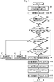
- FIG. 3 is a flowchart showing a flow of throttle opening / closing reference value setting processing in the present embodiment.
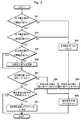
- FIG. 4 is a flowchart showing the flow of the fully closed voltage value detection process in the present embodiment.
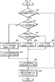
- FIG. 5 is a flowchart showing the flow of the fully closed reference value setting process before the complete explosion in the present embodiment.
- FIG. 6 is a flowchart showing the flow of the fully closed reference value setting process after complete explosion in the present embodiment.
- FIG. 7 is a flowchart showing the flow of the idling time fully closed reference value setting process in the present embodiment.
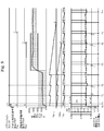
- FIG. 8 is a timing chart for explaining the throttle opening fully closed reference value setting process in the present embodiment.
- FIG. 1 is a schematic cross-sectional view showing the overall configuration of the engine in the present embodiment.
- an engine 1 that is typically an internal combustion engine using gasoline or the like as a fuel is mounted on a vehicle not shown, and includes a cylinder block 2 having a cylinder 2a.
- a cooling water passage 3 through which cooling water for cooling the cylinder 2 a flows is formed in the side wall of the cylinder block 2.
- a cooling water temperature sensor 4 is provided in the cooling water passage 3.
- the cooling water temperature sensor 4 detects the temperature TW of the cooling water flowing through the cooling water passage 3 (hereinafter referred to as the cooling water temperature TW), and outputs the detected value as a voltage signal to an ECU (Electronic Control Unit) 5.
- ECU Electronic Control Unit
- the piston 6 is disposed inside the cylinder 2a.
- the piston 6 is connected to the timing rotor 8 via the crank mechanism 7.
- a crank angle sensor 9 is provided in the vicinity of the timing rotor 8. The crank angle sensor 9 detects the rotation angle of the timing rotor 8 and outputs the detected value to the ECU 5 as a voltage signal.
- a cylinder head 10 is assembled to the upper part of the cylinder 2 a in the cylinder block 2. A space between the upper surface of the piston 6 and the inner surface of the cylinder head 10 defines a combustion chamber 11.
- the cylinder head 10 is provided with a spark plug 12 that ignites the air-fuel mixture in the combustion chamber 11.
- the ignition operation of the spark plug 12 is controlled by the ECU 5 controlling energization to the ignition coil 13.
- the cylinder head 10 is assembled with an intake manifold 14 that communicates with the combustion chamber 11.
- An intake valve 15 is provided in the vicinity of the connecting portion between the intake manifold 14 and the combustion chamber 11 in the cylinder head 10.
- the intake manifold 14 is provided with an injector 16 for injecting fuel in the vicinity of the intake valve 15, and a throttle valve 17 is provided on the upstream side of the injector 16.
- the intake manifold 14 is provided with a throttle opening sensor 18 in the vicinity of the throttle valve 17.
- the throttle opening sensor 18 detects the opening of the throttle valve 17 and outputs the detected value to the ECU 5 as a voltage signal.
- the intake manifold 14 is provided with an intake air temperature sensor 19 on the upstream side of the throttle valve 17.
- the intake air temperature sensor 19 detects the temperature of the air sucked through the air cleaner 20 provided on the upstream side of the intake air temperature sensor 19 and outputs the detected value to the ECU 5 as a voltage signal.
- the intake manifold 14 is provided with a bypass passage 21 that communicates the upstream side and the downstream side of the throttle valve 17 to bypass the throttle valve 17, and an idle speed that opens and closes the bypass passage 21 at the portion of the bypass passage 21.
- a control valve (hereinafter referred to as ISC valve) 22 is provided.
- the ISC valve 22 is driven by an ISC step motor (not shown).
- the ISC valve 22 functions as an idle intake air amount control valve.
- the intake manifold 14 is provided with an intake pressure sensor 23 on the downstream side of the throttle valve 17 and the bypass passage 21.
- the intake pressure sensor 23 detects the pressure of the intake air and outputs the detected value to the ECU 5 as a voltage signal.
- an exhaust manifold 24 communicating with the combustion chamber 11 is assembled to the cylinder head 10.
- An exhaust valve 25 is provided in the vicinity of a communication portion between the combustion chamber 11 and the exhaust manifold 24 in the cylinder head 10.
- the exhaust manifold 24 is provided with a catalytic converter 26 for purifying exhaust gas.
- ECU5 is an arithmetic processing unit provided with a microcomputer etc., and controls operation
- the ECU 5 operates by being supplied with the voltage across the terminals of the battery B mounted on the vehicle.
- FIG. 2 is a block diagram showing the configuration of the control device of the engine 1 shown in FIG.
- the ECU 5 includes an A / D converter 51, a waveform shaping circuit 52, an EEPROM (Electronically Erasable and Programmable Read Only Memory) 53, a ROM (Read Only Memory) 54, and a RAM (Random Access Memory 55).
- a timer 56, a CPU (Central Processing Unit) 57, an ignition circuit 58, and drive circuits 59 and 60 are provided.
- the A / D converter 51 is connected to the throttle opening sensor 18, the intake pressure sensor 23, the cooling water temperature sensor 4, and the intake air temperature sensor 19, and the analog signal input from each sensor is converted into a digital signal. Digitally convert and output to CPU57.
- the A / D converter 51 performs analog / digital conversion on the voltage signal between the terminals of the battery B and outputs it to the CPU 57.
- the waveform shaping circuit 52 performs waveform shaping processing such as smoothing on the signal input from the crank angle sensor 9, and then outputs the signal after the waveform shaping processing to the CPU 57.
- EEPROM53 stores various control information such as the throttle opening fully closed learning value TH EP.
- the ROM 54 stores various control programs and control data for controlling the engine 1.
- the RAM 55 functions as a working area for the CPU 57 that temporarily stores control programs and control data executed by the CPU 57.
- the timer 56 includes a timer for executing various timing processes such as a control cycle for executing a throttle opening fully closed reference value setting process to be described later.
- the CPU 57 is an arithmetic processing unit that controls the operation of the entire engine 1 by executing a control program stored in the ROM 54. Specifically, the CPU 57 controls the ignition operation of the spark plug 12 by controlling energization to the ignition coil 13 via the ignition circuit 58. Further, the CPU 57 controls the operation of the ISC step motor 27 that drives the injector 16 and the ISC valve 22 via the drive circuits 59 and 60.
- the CPU 57 executes a control program stored in the ROM 54, whereby a fully closed voltage value detecting unit 71, a first fully closed reference value setting unit 72, a second fully closed reference value setting unit 73, And functions as a third fully closed reference value setting unit 74. The functions of these units will be described later.
- the ECU 5 functions as a throttle valve full-closed reference value setting device for executing the throttle opening full-closed reference value setting process described below.
- the fully closed reference for calculating the throttle opening with high accuracy based on the minimum value of the output voltage of the throttle opening sensor 18 when the engine 1 is first operated after the vehicle is assembled.
- a value TH REF is set to suppress unnecessary engine stop and driver discomfort.
- FIG. 3 is a flowchart showing the flow of the throttle opening fully closed reference value setting process in the present embodiment.
- the throttle opening fully closed reference value setting process shown in FIG. 3 starts at the timing when the ignition switch of the vehicle is switched from the off state to the on state, and is not synchronized with the rotation of the engine 1, for example, a predetermined value such as 100 msec. It is repeatedly executed for each cycle, and is realized by the CPU 57 of the ECU 5 executing a control program stored in the ROM 54.
- the throttle opening fully closed reference value setting process is thus started, the process proceeds to step S1. Note that an initial value setting process for setting predetermined initial values for various parameters has already been performed before such processing is started.
- step S1 the CPU 57 reads the output voltage value AD of the throttle opening sensor 18 through the A / D converter 51. Thereby, the process of step S1 is completed, and the throttle opening fully closed reference value setting process proceeds to the process of step S2.
- step S2 the fully closed voltage value detection unit 71 outputs when the output voltage value AD of the throttle opening sensor 18 is within a predetermined range based on the output voltage value AD read by the process of step S1.
- a fully closed voltage value detection process for detecting the minimum value of the voltage value AD as the fully closed voltage value TH 0 is executed. Details of the fully closed voltage value detection process will be described later with reference to a flowchart shown in FIG. Thereby, the process of step S2 is completed, and the throttle opening fully closed reference value setting process proceeds to the process of step S3.
- step S3 CPU 57 is, when fully closed the voltage value detection flag indicating whether full or closed voltage value TH 0 is detected F MIN to (full closing voltage value TH 0 is detected, the value is set to 1 If the fully closed voltage value TH 0 is not detected, it is determined whether or not the value of the flag set to 0 is 1 by the fully closed voltage value detecting process in step S2. It is determined whether or not the fully closed voltage value TH 0 is detected. As a result of the determination, if the value of the fully closed voltage value detection flag F MIN is 0, the CPU 57 determines that the fully closed voltage value TH 0 has not been detected by the fully closed voltage value detection process in step S2, and opens the throttle. The fully closed reference value setting process is terminated.
- the CPU 57 determines that the fully closed voltage value TH 0 has been detected by the fully closed voltage value detection process of step S2, and the throttle opening fullness is determined.
- the closed reference value setting process proceeds to the process of step S4.
- step S4 whether or not the CPU 57 has already set a fully closed reference value (hereinafter referred to as an idling fully closed reference value) TH IDL when the rotational speed of the engine 1 is within the range of the idle rotational speed.
- Idle fully closed reference value setting flag F IDL (When the idle fully closed reference value TH IDL has been set, the value is set to 1, and when the idle fully closed reference value TH IDL has not been set) Determines whether or not the idling time fully closed reference value TH IDL has been set by determining whether or not the value of the flag that is set to 0 is 1.
- step S5 the CPU 57 determines that the idling fully closed reference value TH IDL has been set, and sets the throttle opening fully closed reference value. The process proceeds to step S9.
- step S5 the CPU 57 detects the rotational speed NE of the engine 1 based on the voltage signal from the crank angle sensor 9 via the waveform shaping circuit 52. Then, the CPU 57 determines whether or not the engine 1 is in a state before the complete explosion state by determining whether or not the detected rotational speed NE of the engine 1 is equal to or lower than a first predetermined rotational speed such as 1000 rpm. Determine. As a result of the determination, when the rotational speed NE of the engine 1 exceeds the first predetermined rotational speed, the CPU 57 determines that the engine 1 is in a state after the complete explosion state, and the throttle opening fully closed reference value setting process Advances to step S6.
- a first predetermined rotational speed such as 1000 rpm.
- the CPU 57 determines that the engine 1 is in a state before the complete explosion state, and performs the throttle opening fully closed reference value setting process. The process proceeds to step S7.
- step S6 the CPU 57 determines whether or not a fully closed reference value (hereinafter referred to as a fully closed reference value after complete explosion) TH EXP when the engine 1 is in a state after the complete explosion state has been set.
- Full-closed reference value setting flag F EXP after complete explosion If the fully-closed reference value TH EXP after complete explosion has already been set, the value is set to 1, and the fully-closed reference value TH EXP after complete explosion has not been set) In this case, it is determined whether or not the fully closed reference value TH EXP after the complete explosion has been set by determining whether or not the value of the flag whose value is set to 0 is 1.
- step S8 the CPU 57 determines that the fully closed reference value TH EXP after the complete explosion has been set, and the throttle opening fully closed reference.
- the value setting process proceeds to step S9.
- the first fully closed reference value setting unit 72 uses the fully closed voltage value TH 0 detected by the fully closed voltage value detection process of step S2 when the engine 1 is in a state before the complete explosion state.
- the fully-closed reference value before complete explosion is set as TH CRK and the fully-closed reference value TH REF (hereinafter referred to as fully closed reference value before complete explosion) TH CRK . Details of the fully closed reference value setting process before the complete explosion will be described later with reference to the flowchart shown in FIG. Thereby, the process of step S7 is completed, and the throttle opening fully closed reference value setting process proceeds to the process of step S10.
- the second fully closed reference value setting unit 73 sets the fully closed voltage value TH 0 detected by the fully closed voltage value detection process of step S2 as the fully closed reference value TH EXP after the complete explosion.
- a post-explosion fully closed reference value setting process for setting the fully closed reference value TH REF based on either the fully closed reference value TH EXP after the complete explosion or the fully closed reference value TH CRK before the complete explosion is executed. . Details of the fully closed reference value setting process after the complete explosion will be described later with reference to the flowchart shown in FIG. Thereby, the process of step S8 is completed, and the throttle opening fully closed reference value setting process proceeds to the process of step S10.
- step S9 the third fully closed reference value setting unit 74 sets the idle fully closed reference value TH IDL as the fully closed learning value TH EP and the fully closed reference value TH REF. Execute the process. Details of the idling fully closed reference value setting process will be described later with reference to a flowchart shown in FIG. Thereby, the process of step S9 is completed, and the throttle opening fully closed reference value setting process proceeds to the process of step S10.
- step S10 indicating that the CPU57 is, the value of the fully closed voltage value detection flag F MIN indicating whether fully closed voltage value TH 0 is detected 0 (full closing voltage value TH 0 not detected Reset to).
- step S11 CPU 57 may reset the fully closed voltage value TH 0 to the initial setting value #TH. Thereby, the process of step S11 is completed, and the throttle opening fully closed reference value setting process proceeds to the process of step S12.
- step S12 the CPU 57 resets the stability determination voltage minimum value TH IND for determining whether or not the output voltage of the throttle opening sensor 18 is stable to the initial set value #TH. Thereby, the process of step S12 is completed, and the throttle opening fully closed reference value setting process proceeds to the process of step S13.
- step S13 CPU 57 has the count value TM REF of the subtraction timer for voltage stabilization determination for measuring the time interval in which the output voltage of the throttle opening sensor 18 executes a process to determine whether the stable Set to the initial set value #TM REF . Thereby, the process of step S13 is completed and a series of throttle opening fully closed reference value setting processes are complete
- FIG. 4 is a flowchart showing the flow of the fully closed voltage value detection process in the present embodiment.
- step S 4 starts at the timing when the process of step S1 shown in FIG. 3 is completed, and proceeds to the process of step S21.
- the fully closed voltage value detection unit 71 determines whether or not the output voltage value AD of the throttle opening sensor 18 is equal to or higher than a lower limit voltage value TH L (for example, 0.2 V). Result of the determination, when the output voltage value AD is less than the lower limit voltage value TH L, fully closed voltage value detection unit 71 advances the fully closed voltage value detection processing to step 23. On the other hand, when the output voltage value AD is the lower limit voltage value TH L or more, the fully closed voltage value detection unit 71 advances the fully closed voltage value detection processing to step S22.
- a lower limit voltage value TH L for example, 0.2 V
- the fully closed voltage value detection unit 71 determines whether or not the output voltage value AD of the throttle opening sensor 18 is equal to or lower than an upper limit voltage value TH H (for example, 0.8 V). Result of the determination, when the output voltage value AD is less than the upper limit voltage value TH H, the fully closed voltage value detecting unit 71 advances the fully closed voltage detection processing to step 25. On the other hand, the output voltage value AD is if it exceeds the upper limit voltage value TH H, the full-close voltage value detection unit 71 advances the fully closed voltage value detection processing to step S23.
- an upper limit voltage value TH H for example, 0.8 V
- step S23 the fully closed voltage value detection unit 71 resets the full-close voltage value TH 0 to the initial setting value #TH. Thereby, the process of step S23 is completed, and the fully closed voltage value detection process proceeds to the process of step S24.
- step S24 the fully closed voltage value detection unit 71 resets the minimum voltage TH IND for stability determination to the initial set value #TH. Thereby, the process of step S24 is completed, and the fully closed voltage value detection process proceeds to the process of step S29.
- the fully closed voltage value detection unit 71 the output voltage value AD it is determined whether a fully closed voltage value TH 0 or more. As a result of the determination, if the output voltage value AD is equal to or greater than the fully closed voltage value TH 0 , the fully closed voltage value detection unit 71 advances the fully closed voltage value detection process to the process of step S27. On the other hand, when the output voltage value AD is less than the fully closed voltage value TH 0 , the fully closed voltage value detection unit 71 advances the fully closed voltage value detection process to the process of step S26.
- step S26 the fully closed voltage value detection unit 71, it updates the value of the fully closed voltage value TH 0 to the value of the output voltage value AD. Thereby, the process of step S26 is completed, and the fully closed voltage detection process proceeds to the process of step S27.
- the fully closed voltage value detection unit 71 determines that the absolute value (
- step S28 the fully closed voltage value detection unit 71 updates and sets the minimum voltage TH IND for stability determination to the fully closed voltage value TH 0 . Thereby, the process of step S28 is completed, and the fully closed voltage value detection process proceeds to the process of step S29.
- step S29 the fully closed voltage value detection unit 71 sets a count value TM REF of the subtraction timer for voltage stabilization determine the initial setting value #TM REF, it starts counting operation by the subtraction timer. Thereby, the process of step S29 is completed and the throttle opening fully closed reference value setting process ends.
- the fully closed voltage value detection unit 71 by determining whether or not the count value TM REF of the subtraction timer for voltage stabilization determination becomes 0, the fully closed voltage value TH 0 is stable Whether or not a predetermined time (hereinafter referred to as voltage stability determination time) has elapsed since the previous determination. As a result of the determination, if the voltage stability determination time has not elapsed, the fully closed voltage value detection unit 71 ends the series of fully closed voltage value detection processing. On the other hand, when the voltage stability determination time has elapsed, the fully closed voltage value detection unit 71 advances the fully closed voltage value detection process to the process of step S31.
- a predetermined time hereinafter referred to as voltage stability determination time
- step S31 the fully closed voltage value detection unit 71 sets the value of the fully closed voltage value detection flag F MIN to 1 (indicating that the fully closed voltage value TH 0 has been detected). Thereby, the process of step S31 is completed and a series of fully closed voltage value detection processes are complete
- the fully closed voltage value detection unit 71 outputs the output voltage of the throttle opening sensor 18 based on the output voltage value AD read by the process of step S1. when the value AD is within a predetermined range, detecting a minimum value of the output voltage value AD are totally closed voltage value TH 0.
- FIG. 5 is a flowchart showing the flow of the fully closed reference value setting process before the complete explosion in the present embodiment.
- the fully closed reference value setting process before the complete explosion shown in FIG. 5 starts at the timing when it is determined in the process of step S5 shown in FIG. 3 that the engine 1 is in the state before the complete explosion, and proceeds to the process of step S41. .
- the first fully closed reference value setting unit 72 determines that the fully closed voltage value TH 0 detected by the fully closed voltage value detection process is the fully closed reference value TH before the complete explosion set by the previous process. It is determined whether or not it is greater than or equal to CRK . As a result of the determination, if the fully closed voltage value TH 0 is equal to or greater than the fully closed reference value TH CRK before the complete explosion set by the previous process, the first fully closed reference value setting unit 72 performs a series of fully closed before the complete explosion. The reference value setting process ends.
- the first fully closed reference value setting unit 72 performs the fully closed reference value setting process before the complete explosion. The process proceeds to step S42.
- step S42 the first fully closed reference value setting unit 72 sets the fully closed voltage value TH 0 detected by the fully closed voltage value detection process to the fully closed reference value TH CRK before the complete explosion. Thereby, the process of step S42 is completed, and the fully closed reference value setting process before the complete explosion proceeds to the process of step S43.
- step S43 the first fully closed reference value setting unit 72 sets the fully closed reference value TH CRK before the complete explosion to the fully closed reference value TH REF . Thereby, the process in step S43 is completed, and the fully closed reference value setting process before the complete explosion proceeds to the process in step S44.
- step S44 the count of the subtraction timer for setting the fully closed reference value after complete explosion for the first fully closed reference value setting unit 72 to control the time for setting the fully closed reference value TH EXP after complete explosion.
- the value TM END is set to the initial set value #TM END, and the timing operation of the subtraction timer is started. Thereby, the process of step S44 is completed, and the fully closed reference value setting process before the complete explosion proceeds to the process of step S45.
- the first fully closed reference value setting unit 72 counts the subtraction timer for monitoring the post-explosion speed range for controlling the time for monitoring the engine speed range after the complete explosion.
- TM FEX is set to the initial set value #TM FEX, and the time counting operation of the subtraction timer is started. Thereby, the process of step S45 is completed, and the series of fully closed reference value setting process before the complete explosion ends.
- the first full-closed reference value setting unit 72 responds that the rotational speed of the engine 1 is equal to or lower than the first predetermined rotational speed.
- the latest fully closed voltage value TH 0 detected by the fully closed voltage value detection unit 71 before the complete explosion state of the engine 1 to be set can be set as the fully closed reference value TH CRK and the fully closed reference value TH REF before the complete explosion, respectively. is there.
- FIG. 6 is a flowchart showing the flow of the fully closed reference value setting process after the complete explosion in the present embodiment.
- step S51 the second fully closed reference value setting unit 73 sets the fully closed voltage value TH 0 detected by the fully closed voltage value detection process to the fully closed reference value TH EXP after the complete explosion. Thereby, the process of step S51 is completed, and the fully closed reference value setting process after the complete explosion proceeds to the process of step S52.
- step 52 by the second fully closed reference value setting unit 73, after complete explosion count value TM END of the subtraction timer for setting the fully closed reference value to determine whether it is 0, the complete combustion It is determined whether or not a time for setting the rear fully closed reference value TH EXP has elapsed. Result of the determination, if complete explosion count value TM END of the subtraction timer for setting the fully closed reference value is 0, the second fully closed reference value setting unit 73, sets the complete explosion fully closed reference value TH EXP It is determined that the time for performing has elapsed, and the fully closed reference value setting process after the complete explosion proceeds to the process of step S54.
- the second fully closed reference value setting unit 73 sets the complete explosion fully closed reference value TH EXP Therefore, the fully closed reference value setting process after the complete explosion is advanced to the process of step S53.
- the second fully closed reference value setting unit 73 detects the rotational speed NE of the engine 1 based on the voltage signal from the crank angle sensor 9 via the waveform shaping circuit 52. Then, the second fully closed reference value setting unit 73 determines whether the rotational speed NE of the engine 1 exceeds the first predetermined rotational speed but is equal to a predetermined idle rotational speed range (for example, 1200 rpm to 1700 mm). Or it is discriminate
- the second fully closed reference value setting unit 73 advances the fully closed reference value setting process after complete explosion to the process of step S54.
- the second fully closed reference value setting unit 73 advances the fully closed reference value setting process after complete explosion to the process of step S59.
- the second fully closed reference value setting unit 73 determines whether or not the fully closed reference value TH EXP after the complete explosion is equal to or less than the fully closed reference value TH CRK before the complete explosion. As a result of the determination, if the fully closed reference value TH EXP after the complete explosion is equal to or less than the fully closed reference value TH CRK before the complete explosion, the second fully closed reference value setting unit 73 performs the process of setting the fully closed reference value after the complete explosion. The process proceeds to S55.
- the second fully closed reference value setting unit 73 performs the fully closed reference value setting process after the complete explosion. The process proceeds to step S57.
- the second fully closed reference value setting unit 73 after complete explosion fully closed reference value TH EXP is equal to or smaller than a throttle opening fully closed learning value TH EP.
- the second fully closed reference value setting unit 73 is fully closed after the complete explosion.
- the reference value setting process proceeds to the process of step S60.
- the second fully closed reference value setting unit 73 performs the fully closed reference value setting process after the complete explosion. The process proceeds to step S56.
- step S56 the second fully closed reference value setting unit 73 sets the throttle opening fully closed learning value TH EP fully closed reference value TH REF. Thereby, the process of step S56 is completed, and the fully closed reference value setting process after the complete explosion proceeds to the process of step S61.
- the second fully closed reference value setting unit 73 determines whether or not the fully closed reference value TH CRK before the complete explosion is equal to or less than the throttle opening fully closed learning value TH EP stored in the EEPROM 53. Determine. As a result of the determination, if the fully closed reference value TH CRK before the complete explosion is less than or equal to the throttle opening fully closed learning value TH EP , the second fully closed reference value setting unit 73 performs a fully closed reference value setting process after the complete explosion. The process proceeds to S58.
- the second fully closed reference value setting unit 73 performs the fully closed reference value setting process after the complete explosion. The process proceeds to step S56.
- step S58 the second fully closed reference value setting unit 73 sets the fully closed reference value TH CRK before the complete explosion to the fully closed reference value TH REF . Thereby, the process of step S58 is completed, and the fully closed reference value setting process after the complete explosion proceeds to the process of step S61.
- the second fully closed reference value setting unit 73 determines whether or not the count value TM FEX of the subtraction timer for monitoring the rotation speed range after complete explosion is 0, so that It is determined whether or not the time for monitoring the range of the engine speed has elapsed. If the count value TM FEX of the subtraction timer for monitoring the rotation speed range after complete explosion is 0 as a result of the determination, the second fully closed reference value setting unit 73 determines that the monitoring time has passed, The post-explosion fully closed reference value setting process proceeds to step S60.
- the second fully closed reference value setting unit 73 determines that the monitoring time has not elapsed, and complete explosion
- the rear fully closed reference value setting process proceeds to the process of step S63. This is because the rotation speed of the engine 1 is maintained within the range of the rotation speed of the engine 1 corresponding to the state after the complete explosion state, that is, within the second predetermined rotation speed range. Accordingly, it means that the subsequent processing is branched.
- step S60 the second fully closed reference value setting unit 73 sets the fully closed reference value TH EXP after the complete explosion to the fully closed reference value TH REF . Thereby, the process of step S60 is completed, and the fully closed reference value setting process after the complete explosion proceeds to the process of step S61.
- step S61 the second fully closed reference value setting unit 73 sets the fully closed reference value TH REF to the idle fully closed reference value TH IDL . Thereby, the process of step S61 is completed, and the fully closed reference value setting process after the complete explosion proceeds to the process of step S62.
- the second fully closed reference value setting unit 73 sets the value of the fully closed reference value setting flag F EXP after complete explosion to 1 (means that the fully closed reference value TH EXP after complete explosion is set). Set to Yes. Thereby, the process of step S62 is completed, and the series of fully closed reference value setting processes after the complete explosion ends.
- the second fully closed reference value setting unit 73 determines whether or not the fully closed reference value TH EXP after the complete explosion is equal to or less than the fully closed reference value TH CRK before the complete explosion. As a result of the determination, if the fully closed reference value TH EXP after the complete explosion is equal to or less than the fully closed reference value TH CRK before the complete explosion, the second fully closed reference value setting unit 73 performs the process of setting the fully closed reference value after the complete explosion. The process proceeds to S65.
- the second fully closed reference value setting unit 73 performs the fully closed reference value setting process after the complete explosion. The process proceeds to step S64.
- step S64 the second fully closed reference value setting unit 73 sets the fully closed reference value TH CRK before the complete explosion to the fully closed reference value TH REF . Thereby, the process of step S64 is completed, and a series of fully closed reference value setting processes after the complete explosion ends.
- step S65 the second fully closed reference value setting unit 73 sets the fully closed reference value TH EXP after the complete explosion to the fully closed reference value TH REF . Thereby, the process of step S65 is completed, and the series of fully closed reference value setting processes after the complete explosion ends.
- the second full-closed reference value setting unit 73 causes the rotation speed of the engine 1 to exceed the first predetermined rotation speed.
- the latest fully closed voltage value TH 0 is set as the fully closed reference value TH EXP after the complete explosion, and the engine corresponding to that the engine 1 is after the complete explosion state
- the fully closed reference value TH REF is set based on one of the fully closed reference value TH EXP after the complete explosion and the latest fully closed reference value TH CRK before the complete explosion according to the time during which the rotation number of 1 is maintained. It is free.
- the second fully closed reference value setting unit 73 determines whether the engine speed of the engine 1 exceeds the first predetermined engine speed after the complete explosion state but is equal to the predetermined idle engine speed range. Compared to the fully closed reference value TH EXP after the complete explosion and the latest fully closed reference value TH CRK before the complete explosion until the predetermined time elapses when the rotation speed is within a wide range of the second predetermined rotation speed. Then, the smaller value is set as the fully closed reference value TH REF , and after the predetermined time has elapsed, the fully closed reference value TH EXP after the complete explosion is changed to the fully closed reference value TH REF and the idle fully closed reference value TH IDL.
- FIG. 7 is a flowchart showing the flow of the idling fully closed reference value setting process in the present embodiment.
- the idle fully closed reference value setting process shown in FIG. 7 is the timing at which it is determined in step S4 shown in FIG. 3 that the idle fully closed reference value TH IDL has been set, or the process of step S6 shown in FIG. At the timing when it is determined that the fully closed reference value TH EXP has been set after the complete explosion, and the process proceeds to step S71.
- step S71 the third fully closed reference value setting unit 74 determines whether or not the rotational speed of the engine 1 is within a predetermined idle rotational speed range (for example, 1200 rpm to 1700 mm). As a result of the determination, if the rotational speed of the engine 1 is not within the range of the predetermined idle rotational speed, the third fully closed reference value setting unit 74 advances the idle fully closed reference value setting process to the process of step S79. On the other hand, when the rotational speed of the engine 1 is within the range of the predetermined idle rotational speed, the third fully closed reference value setting unit 74 advances the idle fully closed reference value setting process to the process of step S72.
- a predetermined idle rotational speed range for example, 1200 rpm to 1700 mm.
- the third fully closed reference value setting unit 74 determines whether or not the fully closed voltage value TH 0 is the same as the idle fully closed reference value TH IDL . As a result of the determination, if the fully closed voltage value TH 0 is the same as the idle full closed reference value TH IDL , the third fully closed reference value setting unit 74 performs the idle full closed reference value setting process in step S76. Proceed to On the other hand, when the fully closed voltage value TH 0 is not the same as the idle full closed reference value TH IDL , the third fully closed reference value setting unit 74 changes the idle full closed reference value setting process to the process of step S73. Proceed.
- the third full-close reference value setting unit 74 determines whether or not fully closed the voltage value TH 0 is greater than a fully closed reference value TH IDL idle. As a result of the determination, if the fully closed voltage value TH 0 does not exceed the idle fully closed reference value TH IDL , the third fully closed reference value setting unit 74 performs the idle fully closed reference value setting process in step S75. Proceed to On the other hand, if the fully closed voltage value TH 0 exceeds the idle fully closed reference value TH IDL , the third fully closed reference value setting unit 74 performs the idle fully closed reference value setting process in step S74. Proceed to
- step S74 the third fully closed reference value setting unit 74 increases the value of the idle fully closed reference value TH IDL by , for example, 5 mV. Thereby, the process of step S74 is completed, and the idling time fully closed reference value setting process proceeds to the process of step S78.
- step S75 the third fully closed reference value setting unit 74 decreases the value of the idle fully closed reference value TH IDL by , for example, 5 mV. Thereby, the process of step S75 is completed, and the idling time fully closed reference value setting process proceeds to the process of step S78.
- step S76 the third full-close reference value setting unit 74 sets the fully closed reference value TH IDL idle the throttle opening fully closed learning value TH EP. Thereby, the process of step S76 is completed, and the idling time fully closed reference value setting process proceeds to the process of step S77.
- step S77 the third fully closed reference value setting unit 74 sets the value of the idle fully closed reference value setting flag F IDL to 1 (indicating that the idle fully closed reference value TH IDL has been set). Set to. Thereby, the process of step S77 is completed, and the idle time fully closed reference value setting process proceeds to the process of step S78.
- step S78 the third fully closed reference value setting unit 74 sets the idle fully closed reference value TH IDL to the fully closed reference value TH REF . Thereby, the process of step S78 is completed, and the idling fully closed reference value setting process proceeds to the process of step S79.
- the third full-close reference value setting unit 74 stores the throttle opening fully closed learning value TH EP to EEPROM53 every predetermined time (for example, every 3 minutes). Thereby, the process of step S79 is completed, and a series of idle time fully closed reference value setting processes is completed.
- the third fully closed reference value setting unit 74 performs a predetermined process in which the rotational speed of the engine 1 exceeds the first predetermined rotational speed.
- the latest idle-time fully closed reference value TH IDL set by the second fully closed reference value setting unit 73 is used as the throttle opening fully closed learning value TH EP and the fully closed reference value TH.
- Each can be set as REF .
- the fully closed reference value TH REF of the throttle valve 17 is set in the throttle opening fully closed reference value setting process, in the control device for the engine 1, the CPU 57
- the engine speed NE is detected based on the voltage signal of the engine
- the opening of the throttle valve 17 is detected based on the voltage signal from the throttle opening sensor 18, and the detected opening of the throttle valve 17 and the throttle valve are detected.
- the throttle opening TH is calculated based on the 17 fully closed reference value TH REF, and the throttle opening fully closed determination processing, ignition timing calculation processing, based on the detected rotational speed NE and throttle opening TH, respectively.
- the fuel injection amount calculation process and the fuel cut determination process are performed, and the ignition timing obtained by the ignition timing calculation process and the fuel injection amount calculation process are obtained.
- the fuel injection is not executed.
- FIG. 8 is a timing chart for explaining the throttle opening fully closed reference value setting process in the present embodiment.
- Time T T0
- the throttle opening fully closed learning value TH EP is set 0.50 V
- the fully closed reference value TH REF is set throttle opening fully closed learning value TH EP
- complete ⁇ fully closed reference value TH CRK Kan
- the learning upper limit voltage value #THFH (0.80V) is set to the post-explosion fully closed reference value TH EXP , the idle fully closed reference value TH IDL , the fully closed voltage value TH 0 and the stability determination voltage minimum value TH IND.
- the count value TM REF of the subtraction timer for voltage stability judgment is the initial set value #TM REF (0.4 sec)
- the count value TM END of the subtraction timer for setting the fully closed reference value after complete explosion is the initial set value.
- #TM END 2.5 sec
- the initial setting value #TM FEX 1.5 sec
- the value of the fully closed voltage value detected flag F MIN is reset to 0, and the learning upper limit voltage is set to the fully closed voltage value TH 0 and the minimum voltage TH IND for stability determination.
- value #THFH is set again, the count value TM REF of the subtraction timer for the voltage stabilization determination is set default value #TM REF.
- the fully closed reference value TH CRK before the complete explosion is updated to a smaller value at this time because the minimum hold is performed.
- the value of the fully closed voltage value detected flag F MIN is reset to 0, and the learning upper limit voltage is set to the fully closed voltage value TH 0 and the minimum voltage TH IND for stability determination.
- value #THFH is set again, the count value TM REF of the subtraction timer for voltage stabilization determination is set default value #TM REF.
- Time T T4
- T4 the absolute value difference between the voltage minimum value TH IND for stability determination fully closed voltage value TH 0 has elapsed the voltage stabilization determination time in the following conditions 0.01 V, subtraction of voltage stability determination
- the count value TMREF of the timer has become zero. Since the value of the fully closed voltage value detected flag F MIN is 1 and the engine speed exceeds 1000 rpm, the fully closed reference value setting process is executed after the complete explosion, and the fully closed reference value TH REF is set. Is set to the fully closed reference value TH EXP after the complete explosion.
- the count value TMREF of the timer has become zero. Since the predetermined time TM FEX has elapsed while maintaining the engine speed in the second predetermined speed range, it was confirmed that the intake air amount was in the vicinity of the idle speed.
- the current fully closed reference value TH EXP after the complete explosion is set as the fully closed reference value TH REF . Since the setting of the fully closed reference value TH EXP after the complete explosion is completed, the value of the fully closed reference value setting flag F EXP after the complete explosion is set to 1.
- Time T T6
- the absolute value difference between the voltage minimum value TH IND for stability determination fully closed voltage value TH 0 has elapsed the voltage stabilization determination time in the following conditions 0.01 V, subtraction of voltage stability determination
- the count value TMREF of the timer has become zero. Since the engine speed exceeds 1000 rpm and the value of the fully closed reference value setting flag F EXP after the complete explosion is 1, the idling fully closed reference value setting process is performed. Since the engine speed is in the range of the first predetermined speed, the current idle time fully closed reference value TH IDL is set as the fully closed reference value TH REF .
- the value of the idling fully closed reference value setting flag F IDL is set to 1. Thereafter, even when the engine speed is 1000 rpm or less, the operations of the first fully closed reference value setting unit 72 and the second fully closed reference value setting unit 73 are prohibited. After the most accurate fully closed reference value TH REF is set when it is confirmed that the engine speed is in the first predetermined speed range, that is, the intake air amount corresponding to the idle speed is confirmed. The accuracy of the fully closed reference value TH REF is maintained.
- the output voltage AD from the throttle opening sensor 18 that detects the opening of the throttle valve 17 of the engine 1 is within a predetermined range
- the latest fully closed voltage value TH 0 detected by the fully closed voltage value detecting unit 71 is set as a fully closed reference value TH CRK and a fully closed reference value TH REF before the complete explosion of the throttle valve 17 respectively.
- the fully closed voltage value TH 0 is set as a fully closed reference value TH EXP after the complete explosion of the throttle valve 17, and according to the time during which the rotation speed of the engine 1 corresponding to the engine 1 being after the complete explosion state is maintained.
- the throttle valve 17 is fully closed based on one of the fully closed reference value TH EXP after the complete explosion and the latest fully closed reference value TH CRK set by the first fully closed reference value setting unit 72.
- the opening degree of the throttle valve 17 is calculated in the state before the complete explosion of the engine 1 and the initial state after the complete explosion before the engine 1 is operated at a stable idle rotation. It is possible to set the fully closed reference value TH REF to be as accurate as possible, and without providing a separate adjustment mechanism for adjusting the output voltage of the throttle opening sensor 18 after assembling the vehicle. During the first operation of the engine 1, the fully closed reference value TH REF for calculating the throttle opening can be accurately set based on the minimum value of the output voltage AD of the throttle opening sensor 18, and unnecessary engine stop is performed. It is possible to surely prevent the driver and the driver from feeling uncomfortable.
- the throttle valve fully closed reference value setting device is configured such that when the rotational speed of the engine 1 is within a predetermined idle rotational speed range exceeding the first predetermined rotational speed, third fully closed reference value to be set each as the latest throttle opening fully closed learning value of the fully closed reference value TH IDL idle TH EP and fully closed reference value TH REF to fully closed reference value setting unit 73 has set Since the setting unit 74 is provided, the fully closed reference value TH REF for calculating the throttle opening can be set with high accuracy even after the rotational speed of the engine 1 falls within the range of the idle rotational speed. Load operation can be realized.
- fully closed reference value setting device of the throttle valve in an embodiment of the present invention is provided with a third throttle opening fully closed learning value TH EP to fully closed reference value setting unit 74 has set of the engine control system 1 is EEPROM53 Therefore, the fully closed reference value TH REF for calculating the throttle opening with high accuracy can be used even when the engine 1 is started next time.
- the second fully closed reference value setting unit 73 is configured such that, after the complete explosion state, the rotational speed of the engine 1 is the first predetermined rotational speed. Is within the second predetermined rotational speed range that is equal to or wider than the predetermined idle rotational speed range, but the fully closed reference value after complete explosion until the predetermined time has elapsed. Comparing TH EXP with the latest fully closed reference value TH CRK before complete explosion and setting the smaller value as the fully closed reference value TH REF.
- the fully closed reference value TH after complete explosion EXP is set as a fully closed reference value TH REF and an idle fully closed reference value TH IDL , respectively, and when the engine speed is not within the range of the second predetermined engine speed, the fully closed reference value after complete explosion Value TH EXP and latest fully closed reference value TH before complete explosion Respectively set smaller value by comparing the CRK and the throttle opening fully closed learning value stored in the EEPROM 53 TH EP as fully closed reference value TH REF and fully closed reference value TH IDL idle. According to such a configuration, even during the period when the engine 1 is not stable after the complete explosion state, including the current and next start-up of the engine 1, a fully closed reference for accurate throttle opening calculation.
- the value TH REF can be used.
- the fully closed reference value setting device of the throttle valve in an embodiment of the present invention after the third fully closed reference value setting unit 74, sets the throttle opening fully closed learning value TH EP is first of all Since the processing of both the closed reference value setting unit 72 and the second fully closed reference value setting unit 73 is prohibited, the fully closed reference value TH REF for calculating the throttle opening with high accuracy is continuously maintained after the engine 1 is started. It can be used efficiently.
- the type, arrangement, number, and the like of the members are not limited to the above-described embodiments, and the components depart from the gist of the invention, such as appropriately replacing the constituent elements with those having the same operational effects. Of course, it can be appropriately changed within the range not to be.
- the engine To provide a throttle valve fully-closed reference value setting device and an engine control device that can reliably suppress a situation in which the vehicle stops unnecessarily or hunts, and can reliably prevent the driver from feeling uncomfortable. It is expected that it can be widely applied to the engine of vehicles such as automobiles because of its general-purpose universal character.
Landscapes
- Engineering & Computer Science (AREA)
- Chemical & Material Sciences (AREA)
- Combustion & Propulsion (AREA)
- Mechanical Engineering (AREA)
- General Engineering & Computer Science (AREA)
- Combined Controls Of Internal Combustion Engines (AREA)
- Control Of Throttle Valves Provided In The Intake System Or In The Exhaust System (AREA)
Abstract
エンジン(1)の完爆状態前において、全閉電圧値検出部(71)が検出した最新の全閉電圧値(TH0)を、スロットルバルブ(17)の完爆前全閉基準値(THCRK)及び全閉基準値(THREF)としてそれぞれ設定する第1の全閉基準値設定部(72)と、エンジン(1)の完爆状態後において、全閉電圧値検出部(71)が検出した最新の全閉電圧値(TH0)をスロットルバルブ(17)の完爆後全閉基準値(THEXP)として設定すると共に、エンジン(1)が完爆状態後であることに対応したエンジン(1)の回転数が維持された時間に応じて、完爆後全閉基準値(THEXP)と第1の全閉基準値設定部(72)が設定した最新の完爆前全閉基準値(THCRK)との何れか一方に基づいてスロットルバルブ(17)の全閉基準値(THREF)を設定する第2の全閉基準値設定部(73)と、を備える。
Description
本発明は、スロットルバルブの全閉基準値設定装置及びエンジンの制御装置に関し、特に、スロットル開度センサの検出値を用いてスロットルバルブの開度を算出するための全閉基準値を設定するスロットルバルブの全閉基準値設定装置及びかかる全閉基準値設定装置を用いてスロットルバルブの開度を算出しながらエンジンの運転状態を制御するエンジンの制御装置に関する。
近年、排気ガスの低減や燃費向上を目的として、小型自動二輪車等の車両において燃料噴射装置が採用されるようになっている。かかる燃料噴射装置は、エンジンの吸気通路に設置されたスロットルバルブの開度に応じて燃料噴射を行うものであるため、スロットルバルブの全閉値を正確に算出して、その開度を正確に算出することが求められる。
特許文献1は、スロットル開度検出装置に関し、スロットルバルブの開度に対応した出力電圧を出力するスロットル開度センサを備え、エンジン運転中にスロットル開度センサの出力電圧の最小値又は最大値を検出し、最小値又は最大値の検出値を学習値として記憶・更新し、学習記憶値に基づいてスロットルバルブの全閉状態を検出する構成を開示する。
特許文献2は、スロットル開度検出装置に関し、スロットルバルブの開度に対応した出力電圧を出力するスロットル開度センサを備え、スロットル開度センサから出力された出力電圧と記憶手段に記憶された出力電圧の最小値とを比較することによってスロットルバルブの全閉状態を検出すると共に、エンジンの完爆後又は暖気終了直後に記憶手段に記憶された出力電圧の最小値を初期化する構成を開示する。
しかしながら、本発明者が検討するところでは、特許文献1及び特許文献2が開示するスロットル開度検出装置は、エンジンの運転中にスロットル開度センサの出力電圧の最小値を検出し、その検出値を学習値として記憶・更新し、かかる学習記憶値に基づいてスロットルバルブの全閉状態を検出する構成を有するものであるが、小型自動二輪車等の車両においては、燃料噴射装置を構成する部品、特に燃料噴射装置が用いるセンサ部品について、コストを低減することが求められている現状にある。
詳しくは、燃料噴射装置で用いられるスロットル開度センサについては、コストの低減や組み付けの容易さを実現すべく、出力電圧調整機構を廃止することが求められている。かかる出力電圧調整機構とは、スロットル開度センサの組み付け時に、スロットルバルブの全閉状態に対し出力電圧が所定の値になるようにスロットル開度センサの出力電圧を調整するためのものである。
ここで、かかる出力電圧調整機構を廃止した場合、車両組み立てた後に、スロットル開度検出装置が最初に動作する際には、装置内に記憶されている出力電圧の最小値の学習記憶値は工場出荷時の初期値となる。このため、車両組み立て後の最初の動作時においては、スロットル開度検出装置内に記憶されている学習記憶値が実際の出力電圧の最小値から乖離している状態になり、スロットルバルブの全閉状態を正確に検出することができない事態につながる可能性がある。そして、スロットルバルブの全閉状態を正確に検出することができない場合には、スロットルバルブが開いているのにもかかわらずスロットルバルブが全閉状態であると判定する事態が生じ、結果としてエンジンが不要に停止したり、運転者等に違和感を与えたりすることがある。
つまり、例えば、アイドル運転時にエンジン回転数を一定に保つために吸入空気量をフィードバック制御するアイドル回転数制御においては、フィードバック制御はスロットルバルブの全閉状態が検出された場合に実施されることになるが、スロットルバルブが開いているのにもかかわらずスロットルバルブが全閉状態であると判定された場合には、フィードバック制御によって吸入空気量は減量されてしまう。そして、このとき、スロットルバルブが全閉状態に戻された場合には、吸入空気量が減量されているためにエンジン回転数が不要に低下してしまい、エンジンストールに至る可能性も生じてしまう。
また、所定のエンジン回転数以上であり、かつ、スロットル開度が全閉状態であるときに、典型的には減速走行中に、燃費向上や排出ガスの低減を目的として燃料噴射を停止する制御が行われる場合には、スロットルバルブが開いているのにもかかわらず全閉状態であると判定されてしまうと、スロットルバルブが開けられてエンジン回転数が上昇する際に燃料噴射が停止される事態が生じ、エンジンの動作にいわゆるハンチングが発生等して、運転者等に違和感を与えることも考えられる。
ここで、本発明者の更なる検討によれば、以上のような事態の発生をより確実に防止するには、エンジンが安定したアイドル回転で運転されるようになる以前のエンジンの完爆前の状態や完爆後の初期の状態において、スロットルバルブの開度を算出するための全閉基準値を可能な限り高い精度で設定しておき、その後の安定したアイドル回転での運転時における全閉基準値を設定する際にそれを利用して、迅速かつ正確にかかる全閉基準値を設定することが極めて効果的であることが判明した。
本発明は、以上の検討を経てなされたもので、スロットル開度センサの検出値を用いてスロットルバルブの開度を算出するための全閉基準値を設定する際に出力電圧調整機構を省略しても、エンジンが不要に停止したりハンチングしてしまう事態を確実に抑制して、運転者等に違和感を与えることを確実に抑制できるスロットルバルブの全閉基準値設定装置及びエンジンの制御装置を提供することを目的とする。
以上の目的を達成するべく、本発明は、エンジンのスロットルバルブの開度を検出するスロットル開度センサからの出力電圧が所定範囲内にあるときに、前記出力電圧の最小値をスロットル開度の全閉電圧値として検出する全閉電圧値検出部と、前記エンジンの回転数が第1の所定回転数以下であることに対応する前記エンジンの完爆状態前において、前記全閉電圧値検出部が検出した最新の全閉電圧値を、前記スロットルバルブの完爆前全閉基準値及び全閉基準値としてそれぞれ設定自在である第1の全閉基準値設定部と、前記エンジンの回転数が前記第1の所定回転数を超えていることに対応する前記エンジンの完爆状態後において、前記全閉電圧値検出部が検出した最新の全閉電圧値を前記スロットルバルブの完爆後全閉基準値として設定すると共に、前記エンジンが完爆状態後であることに対応した前記エンジンの回転数が維持された時間に応じて、前記完爆後全閉基準値と前記第1の全閉基準値設定部が設定した最新の完爆前全閉基準値との何れか一方に基づいて前記スロットルバルブの全閉基準値を設定自在である第2の全閉基準値設定部とを備えることを第1の局面とするスロットルバルブの全閉基準値設定装置である。
また、本発明は、かかる第1の局面に加えて、前記完爆状態後において、前記エンジンの回転数が前記第1の所定回転数を超えた所定のアイドル回転数の範囲内にあるときに、前記第2の全閉基準値設定部が設定していた最新のアイドル時全閉基準値を、前記スロットルバルブの全閉学習値及び全閉基準値としてそれぞれ設定自在である第3の全閉基準値設定部を更に備えることを第2の局面とする。
また、本発明は、かかる第2の局面に加えて、前記第3の全閉基準値設定部が設定した前記全閉学習値を前記エンジンの制御系が備えるEEPROMに記憶することを第3の局面とする。
また、本発明は、かかる第3の局面に加えて、前記第2の全閉基準値設定部は、前記完爆状態後において、前記エンジンの回転数が、前記第1の所定回転数を超えているが、前記所定のアイドル回転数の範囲と等しいかより広い範囲である第2の所定回転数の範囲内にあるときに、所定時間が経過するまでは、前記完爆後全閉基準値と前記第1の全閉基準値設定部が設定した最新の完爆前全閉基準値とを比較して小さい方の値を前記スロットルバルブの全閉基準値として設定し、所定時間が経過した以降は、前記完爆後全閉基準値を前記スロットルバルブの全閉基準値及び前記アイドル時全閉基準値としてそれぞれ設定し、前記エンジンの回転数が、前記第2の所定回転数の範囲内にないときに、前記完爆後全閉基準値と前記第1の全閉基準値設定部が設定した最新の完爆前全閉基準値と前記EEPROMに記憶された前記全閉学習値とを比較して小さい方の値を前記スロットルバルブの全閉基準値及び前記アイドル時全閉基準値としてそれぞれ設定することを第4の局面とする。
また、本発明は、かかる第3又は第4の局面に加えて、前記第3の全閉基準値設定部が前記全閉学習値を設定した後は、前記第1の全閉基準値設定部及び前記第2の全閉基準値設定部の双方の処理を禁止することを第5の局面とする。
また、本発明は、別の局面として、かかる第1から第5の局面のいずれかのスロットルバルブの全閉基準値設定装置を用いて、エンジンのスロットルバルブの開度を算出しながら前記エンジンの運転状態を制御自在であるエンジンの制御装置である。
本発明の第1の局面におけるスロットルバルブの全閉基準値設定装置においては、エンジンが安定したアイドル回転で運転されるようになる以前のエンジンの完爆前の状態や完爆後の初期の状態において、スロットルバルブの開度を算出するための全閉基準値を可能な限り高い精度で設定しておくことが可能となり、スロットル開度センサの出力電圧を調整する調整機構を別途設けることなく、車両を組み立てた後の最初のエンジンの動作時において、スロットル開度センサの出力電圧の最小値に基づいて精度よくスロットルバルブの全閉基準値を設定することができ、不要なエンジンの停止や運転者等に違和感を与えることを確実に抑制することができる。
また、本発明の第2の局面におけるスロットルバルブの全閉基準値設定装置においては、エンジンの回転数がアイドル回転数の範囲内に入った後も精度よくスロットルバルブの全閉基準値を設定することができ、安定したアイドル運転及び負荷運転を実現することができる。
また、本発明の第3の局面におけるスロットルバルブの全閉基準値設定装置においては、次回のエンジンの始動時においても精度のよいスロットルバルブの全閉基準値を利用することができる。
また、本発明の第4の局面におけるスロットルバルブの全閉基準値設定装置においては、今回及び次回のエンジンの始動時を含め、完爆状態後にエンジンの回転数が安定しない期間であっても、精度のよいスロットルバルブの全閉基準値を利用することができる。
また、本発明の第5の局面におけるスロットルバルブの全閉基準値設定装置においては、エンジンの始動後に精度のよい全閉基準値を持続的に効率よく利用することができる。
また、本発明の別の局面におけるエンジンの制御装置によれば、不要なエンジンの停止や運転者等に違和感を与えることを確実に抑制可能なエンジンの制御装置を実現することができる。
以下、図1から図8を適宜参照して、本発明の実施形態におけるスロットルバルブの全閉基準値設定装置及びエンジンの制御装置につき、詳細に説明する。
〔エンジンの構成〕
始めに、図1を参照して、本発明の実施形態におけるスロットルバルブの全閉基準値設定装置及びエンジンの制御装置が適用されるエンジンの構成について説明する。
始めに、図1を参照して、本発明の実施形態におけるスロットルバルブの全閉基準値設定装置及びエンジンの制御装置が適用されるエンジンの構成について説明する。
図1は、本実施形態におけるエンジンの全体構成を示す模式的断面図である。
図1に示すように、典型的にはガソリン等を燃料とする内燃機関であるエンジン1は、図示を省略する車両に搭載され、シリンダ2aを有するシリンダブロック2を備える。シリンダブロック2の側壁内には、シリンダ2aを冷却するための冷却水が流通する冷却水通路3が形成されている。冷却水通路3には、冷却水温センサ4が設けられている。冷却水温センサ4は、冷却水通路3を流通する冷却水の温度TW(以下、冷却水温度TWと記す)を検出し、検出値を電圧信号としてECU(Electronic Control Unit)5に出力する。なお、図中では、1個のシリンダ2aのみを示しているが、もちろん複数個のシリンダ2aを設けてもかまわない。
シリンダ2aの内部には、ピストン6が配置されている。ピストン6は、クランク機構7を介してタイミングローター8に接続されている。タイミングローター8の近傍には、クランク角センサ9が設けられている。クランク角センサ9は、タイミングローター8の回転角度を検出し、検出値を電圧信号としてECU5に出力する。シリンダブロック2におけるシリンダ2aの上部には、シリンダヘッド10が組み付けられている。ピストン6の上面とシリンダヘッド10の内面との間の空間は燃焼室11を画成している。
シリンダヘッド10には、燃焼室11内の混合気に点火する点火プラグ12が設けられている。点火プラグ12の点火動作は、ECU5が点火コイル13への通電を制御することによって制御される。
シリンダヘッド10には、燃焼室11と連通するインテークマニホールド14が組み付けられている。シリンダヘッド10におけるインテークマニホールド14と燃焼室11との連絡部位近傍には、吸気バルブ15が設けられている。インテークマニホールド14には、吸気バルブ15の近傍に燃料を噴射するインジェクター16が設けられていると共に、インジェクター16の上流側にスロットルバルブ17が設けられている。
インテークマニホールド14には、スロットルバルブ17の近傍において、スロットル開度センサ18が設けられている。スロットル開度センサ18は、スロットルバルブ17の開度を検出し、検出値を電圧信号としてECU5に出力する。また、インテークマニホールド14には、スロットルバルブ17の上流側において、吸気温センサ19が設けられている。吸気温センサ19は、吸気温センサ19の上流側に設けられたエアクリーナー20を介して吸入された空気の温度を検出し、検出値を電圧信号としてECU5に出力する。
インテークマニホールド14には、スロットルバルブ17の上流側と下流側とを連通して、スロットルバルブ17をバイパスするバイパス通路21が設けられると共に、バイパス通路21の部位において、バイパス通路21を開閉するアイドルスピードコントロールバルブ(以下、ISCバルブと記す)22が設けられている。ISCバルブ22は、図示を省略するISCステップモータによって駆動される。ISCバルブ22は、アイドル吸入空気量制御弁として機能する。また、インテークマニホールド14には、スロットルバルブ17及びバイパス通路21の下流側において、吸気圧センサ23が設けられている。吸気圧センサ23は、吸入空気の圧力を検出し、検出値を電圧信号としてECU5に出力する。
一方で、シリンダヘッド10には、燃焼室11と連通するエキゾーストマニホールド24が組み付けられている。シリンダヘッド10における燃焼室11とエキゾーストマニホールド24との連絡部位近傍には、排気バルブ25が設けられている。エキゾーストマニホールド24には、排気ガスを浄化するための触媒コンバーター26が設けられている。
ECU5は、マイクロコンピュータ等を備えた演算処理装置であり、エンジン1全体の動作を制御する。ECU5には、車両に搭載されたバッテリBの端子間電圧が供給されて動作する。
〔エンジンの制御装置の構成〕
次に、更に図2をも参照して、図1に示すエンジン1の制御装置として協働して機能するECU5及びその周辺機器の構成について説明する。
次に、更に図2をも参照して、図1に示すエンジン1の制御装置として協働して機能するECU5及びその周辺機器の構成について説明する。
図2は、図1に示すエンジン1の制御装置の構成を示すブロック図である。
図2に示すように、ECU5は、A/D変換器51、波形整形回路52、EEPROM(Electronically Erasable and Programmable Read Only Memory)53、ROM(Read Only Memory)54、RAM(Random Access Memory)55、タイマ56、CPU(Central Processing Unit)57、点火回路58、及び駆動回路59、60を備える。A/D変換器51は、スロットル開度センサ18、吸気圧センサ23、冷却水温センサ4、吸気温センサ19に接続され、各センサから入力されたアナログ形態の信号をデジタル形態の信号にアナログ/デジタル変換してCPU57に出力する。また、A/D変換器51は、バッテリBの端子間電圧信号をアナログ/デジタル変換してCPU57に出力する。波形整形回路52は、クランク角センサ9から入力された信号に対して平滑化等の波形整形処理を施した後、その波形成形処理後の信号をCPU57に出力する。EEPROM53は、スロットル開度全閉学習値THEP等の各種制御情報を記憶する。ROM54は、エンジン1を制御するための各種制御プログラム及び制御データを記憶している。
RAM55は、CPU57が実行している制御プログラムや制御データを一時的に記憶するCPU57のワーキングエリアとして機能する。タイマ56は、後述するスロットル開度全閉基準値設定処理を実行する制御周期等の各種計時処理を実行するタイマを含む。CPU57は、ROM54内に格納されている制御プログラムを実行することによって、エンジン1全体の動作を制御する演算処理装置である。詳しくは、CPU57は、点火回路58を介して点火コイル13への通電を制御することによって、点火プラグ12の点火動作を制御する。また、CPU57は、駆動回路59、60を介してインジェクター16及びISCバルブ22を駆動するISCステップモータ27の動作を制御する。また、CPU57は、ROM54内に格納されている制御プログラムを実行することによって、全閉電圧値検出部71、第1の全閉基準値設定部72、第2の全閉基準値設定部73、及び第3の全閉基準値設定部74として機能する。これら各部の機能については後述する。
〔スロットル開度全閉基準値設定処理〕
以上の構成を有するエンジン1の制御装置では、ECU5が以下に示すスロットル開度全閉基準値設定処理を実行するスロットルバルブの全閉基準値設定装置として機能し、スロットル開度センサ18の出力電圧を調整する調整機構を別途設けることなく、車両組み立てた後の最初のエンジン1の動作時において、スロットル開度センサ18の出力電圧の最小値に基づいて精度よくスロットル開度算出用の全閉基準値THREFを設定し、不要なエンジンの停止や運転者等に違和感を与えることを抑制する。以下、更に図3に示すフローチャートをも参照して、スロットル開度全閉基準値設定処理を実行する際のECU5の動作について説明する。
以上の構成を有するエンジン1の制御装置では、ECU5が以下に示すスロットル開度全閉基準値設定処理を実行するスロットルバルブの全閉基準値設定装置として機能し、スロットル開度センサ18の出力電圧を調整する調整機構を別途設けることなく、車両組み立てた後の最初のエンジン1の動作時において、スロットル開度センサ18の出力電圧の最小値に基づいて精度よくスロットル開度算出用の全閉基準値THREFを設定し、不要なエンジンの停止や運転者等に違和感を与えることを抑制する。以下、更に図3に示すフローチャートをも参照して、スロットル開度全閉基準値設定処理を実行する際のECU5の動作について説明する。
図3は、本実施形態におけるスロットル開度全閉基準値設定処理の流れを示すフローチャートである。
図3に示すスロットル開度全閉基準値設定処理は、車両のイグニッションスイッチがオフ状態からオン状態に切り換えられたタイミングで開始となり、エンジン1の回転とは同期せずに、例えば100msec等の所定周期毎に繰り返し実行されるもので、ECU5のCPU57がROM54内に格納されている制御プログラムを実行することによって実現される。このようにスロットル開度全閉基準値設定処理が開始されると、ステップS1の処理へと進む。なお、かかる処理が開始される前には、各種パラメータに所定の初期値を設定する初期値設定処理が既になされている。
ステップS1の処理では、CPU57が、A/D変換器51を介してスロットル開度センサ18の出力電圧値ADを読み込む。これにより、ステップS1の処理は完了し、スロットル開度全閉基準値設定処理はステップS2の処理に進む。
ステップS2の処理では、全閉電圧値検出部71が、ステップS1の処理によって読み込まれた出力電圧値ADに基づいて、スロットル開度センサ18の出力電圧値ADが所定範囲内にあるときに出力電圧値ADの最小値を全閉電圧値TH0として検出する全閉電圧値検出処理を実行する。全閉電圧値検出処理の詳細については、図4に示すフローチャートを参照して後述する。これにより、ステップS2の処理は完了し、スロットル開度全閉基準値設定処理はステップS3の処理に進む。
ステップS3の処理では、CPU57が、全閉電圧値TH0が検出されたか否かを示す全閉電圧値検出フラグFMIN(全閉電圧値TH0が検出された場合、値が1に設定され、全閉電圧値TH0が検出されていない場合には、値が0に設定されるフラグ)の値が1であるか否かを判別することによって、ステップS2の全閉電圧値検出処理によって全閉電圧値TH0が検出されたか否かを判別する。判別の結果、全閉電圧値検出フラグFMINの値が0である場合、CPU57は、ステップS2の全閉電圧値検出処理によって全閉電圧値TH0が検出されていないと判断し、スロットル開度全閉基準値設定処理を終了する。一方、全閉電圧値検出フラグFMINの値が1である場合には、CPU57は、ステップS2の全閉電圧値検出処理によって全閉電圧値TH0が検出されたと判断し、スロットル開度全閉基準値設定処理をステップS4の処理に進める。
ステップS4の処理では、CPU57が、エンジン1の回転数がアイドル回転数の範囲内にあるときの全閉基準値(以下、アイドル時全閉基準値と記す)THIDLが設定済みであるか否かを示すアイドル時全閉基準値設定フラグFIDL(アイドル時全閉基準値THIDLが設定済みである場合、値が1に設定され、アイドル時全閉基準値THIDLが設定済みでない場合には、値が0に設定されるフラグ)の値が1であるか否かを判別することによって、アイドル時全閉基準値THIDLが設定済みであるか否かを判別する。判別の結果、アイドル時全閉基準値設定フラグFIDLの値が0である場合、CPU57は、アイドル時全閉基準値THIDLが設定済みでないと判断し、スロットル開度全閉基準値設定処理をステップS5の処理に進める。一方、アイドル時全閉基準値設定フラグFIDLの値が1である場合には、CPU57は、アイドル時全閉基準値THIDLが設定済みであると判断し、スロットル開度全閉基準値設定処理をステップS9の処理に進める。
ステップS5の処理では、CPU57が、波形整形回路52を介したクランク角センサ9からの電圧信号に基づいてエンジン1の回転数NEを検出する。そして、CPU57は、検出されたエンジン1の回転数NEが例えば1000rpm等の第1の所定回転数以下であるかを判別することによって、エンジン1が完爆状態前の状態にあるか否かを判別する。判別の結果、エンジン1の回転数NEが第1の所定回転数を超えている場合、CPU57は、エンジン1が完爆状態後の状態にあると判断し、スロットル開度全閉基準値設定処理をステップS6の処理に進める。一方、エンジン1の回転数NEが第1の所定回転数以下である場合には、CPU57は、エンジン1が完爆状態前の状態にあると判断し、スロットル開度全閉基準値設定処理をステップS7の処理に進める。
ステップS6の処理では、CPU57が、エンジン1が完爆状態後の状態にあるときの全閉基準値(以下、完爆後全閉基準値と記す)THEXPが設定済みであるか否かを示す完爆後全閉基準値設定フラグFEXP(完爆後全閉基準値THEXPが設定済みである場合、値が1に設定され、完爆後全閉基準値THEXPが設定済みでない場合には、値が0に設定されるフラグ)の値が1であるか否かを判別することによって、完爆後全閉基準値THEXPが設定済みであるか否かを判別する。判別の結果、完爆後全閉基準値設定フラグFEXPの値が0である場合、CPU57は、完爆後全閉基準値THEXPが設定済みでないと判断し、スロットル開度全閉基準値設定処理をステップS8の処理に進める。一方、完爆後全閉基準値設定フラグFEXPの値が1である場合には、CPU57は、完爆後全閉基準値THEXPが設定済みであると判断し、スロットル開度全閉基準値設定処理をステップS9の処理に進める。
ステップS7の処理では、第1の全閉基準値設定部72が、ステップS2の全閉電圧値検出処理によって検出された全閉電圧値TH0をエンジン1が完爆状態前の状態にあるときの全閉基準値(以下、完爆前全閉基準値と記す)THCRK及び全閉基準値THREFとして設定する完爆前全閉基準値設定処理を実行する。完爆前全閉基準値設定処理の詳細については、図5に示すフローチャートを参照して後述する。これにより、ステップS7の処理は完了し、スロットル開度全閉基準値設定処理はステップS10の処理に進む。
ステップS8の処理では、第2の全閉基準値設定部73が、ステップS2の全閉電圧値検出処理によって検出された全閉電圧値TH0を完爆後全閉基準値THEXPとして設定すると共に、完爆後全閉基準値THEXPと完爆前全閉基準値THCRKとの何れか一方に基づいて全閉基準値THREFを設定する完爆後全閉基準値設定処理を実行する。完爆後全閉基準値設定処理の詳細については、図6に示すフローチャートを参照して後述する。これにより、ステップS8の処理は完了し、スロットル開度全閉基準値設定処理はステップS10の処理に進む。
ステップS9の処理では、第3の全閉基準値設定部74が、アイドル時全閉基準値THIDLを全閉学習値THEP及び全閉基準値THREFとして設定するアイドル時全閉基準値設定処理を実行する。アイドル時全閉基準値設定処理の詳細については、図7に示すフローチャートを参照して後述する。これにより、ステップS9の処理は完了し、スロットル開度全閉基準値設定処理はステップS10の処理に進む。
ステップS10の処理では、CPU57が、全閉電圧値TH0が検出されたか否かを示す全閉電圧値検出フラグFMINの値を0(全閉電圧値TH0が検出されていないことを示す)にリセットする。これにより、ステップS10の処理は完了し、スロットル開度全閉基準値設定処理はステップS11の処理に進む。
ステップS11の処理では、CPU57が、全閉電圧値TH0を初期設定値#THにリセットする。これにより、ステップS11の処理は完了し、スロットル開度全閉基準値設定処理はステップS12の処理に進む。
ステップS12の処理では、CPU57が、スロットル開度センサ18の出力電圧が安定したか否かを判断するための安定判断用の電圧最小値THINDを初期設定値#THにリセットする。これにより、ステップS12の処理は完了し、スロットル開度全閉基準値設定処理はステップS13の処理に進む。
ステップS13の処理では、CPU57が、スロットル開度センサ18の出力電圧が安定したか否かを判断する処理を実行する時間間隔を計測するための電圧安定判断用の減算タイマのカウント値TMREFを初期設定値#TMREFに設定する。これにより、ステップS13の処理は完了し、一連のスロットル開度全閉基準値設定処理は終了する。
〔全閉電圧値検出処理〕
次に、更に図4に示すフローチャートをも参照して、ステップS2の全閉電圧値検出処理について詳しく説明する。
次に、更に図4に示すフローチャートをも参照して、ステップS2の全閉電圧値検出処理について詳しく説明する。
図4は、本実施形態における全閉電圧値検出処理の流れを示すフローチャートである。
図4に示す全閉電圧値検出処理は、図3に示すステップS1の処理が完了したタイミングで開始となり、ステップS21の処理へと進む。
ステップS21の処理では、全閉電圧値検出部71が、スロットル開度センサ18の出力電圧値ADが下限電圧値THL(例えば0.2V)以上であるか否かを判別する。判別の結果、出力電圧値ADが下限電圧値THL未満である場合、全閉電圧値検出部71は全閉電圧値検出処理をステップ23の処理に進める。一方、出力電圧値ADが下限電圧値THL以上である場合には、全閉電圧値検出部71は全閉電圧値検出処理をステップS22の処理に進める。
ステップS22の処理では、全閉電圧値検出部71が、スロットル開度センサ18の出力電圧値ADが上限電圧値THH(例えば0.8V)以下であるか否かを判別する。判別の結果、出力電圧値ADが上限電圧値THH以下である場合、全閉電圧値検出部71は全閉電圧値検出処理をステップ25の処理に進める。一方、出力電圧値ADが上限電圧値THHを超えている場合には、全閉電圧値検出部71は全閉電圧値検出処理をステップS23の処理に進める。
ステップS23の処理では、全閉電圧値検出部71が、全閉電圧値TH0を初期設定値#THにリセットする。これにより、ステップS23の処理は完了し、全閉電圧値検出処理はステップS24の処理に進む。
ステップS24の処理では、全閉電圧値検出部71が、安定判断用の電圧最小値THINDを初期設定値#THにリセットする。これにより、ステップS24の処理は完了し、全閉電圧値検出処理はステップS29の処理に進む。
ステップS25の処理では、全閉電圧値検出部71が、出力電圧値ADが全閉電圧値TH0以上であるか否かを判別する。判別の結果、出力電圧値ADが全閉電圧値TH0以上である場合、全閉電圧値検出部71は全閉電圧値検出処理をステップS27の処理に進める。一方、出力電圧値ADが全閉電圧値TH0未満である場合には、全閉電圧値検出部71は全閉電圧値検出処理をステップS26の処理に進める。
ステップS26の処理では、全閉電圧値検出部71が、全閉電圧値TH0の値を出力電圧値ADの値に更新する。これにより、ステップS26の処理は完了し、全閉電圧検出処理はステップS27の処理に進む。
ステップS27の処理では、全閉電圧値検出部71が、全閉電圧値TH0と安定判断用の電圧最小値THINDとの差分値の絶対値(|TH0-THIND|)が所定値D以下であるか否かを判別することによって、全閉電圧値TH0が安定しているか否かを判定する。判別の結果、絶対値が所定値Dを超えている場合、全閉電圧値検出部71は、全閉電圧値TH0は安定していないと判断し、全閉電圧値検出処理をステップS28の処理に進める。一方、絶対値が所定値D以下である場合には、全閉電圧値検出部71は、全閉電圧値TH0は安定していると判断し、全閉電圧値検出処理をステップS30の処理に進める。
ステップS28の処理では、全閉電圧値検出部71が、安定判断用の電圧最小値THINDを全閉電圧値TH0に更新して設定する。これにより、ステップS28の処理は完了し、全閉電圧値検出処理はステップS29の処理に進む。
ステップS29の処理では、全閉電圧値検出部71が、電圧安定判断用の減算タイマのカウント値TMREFを初期設定値#TMREFに設定し、減算タイマによる計時動作を開始する。これにより、ステップS29の処理は完了し、スロットル開度全閉基準値設定処理は終了する。
ステップS30の処理では、全閉電圧値検出部71が、電圧安定判断用の減算タイマのカウント値TMREFが0になったか否かを判別することによって、全閉電圧値TH0が安定しているか否かを、前回判定してから所定時間(以下、電圧安定判断時間と記す)が経過したか否かにより判別する。判別の結果、電圧安定判断時間が経過していない場合、全閉電圧値検出部71は一連の全閉電圧値検出処理を終了する。一方、電圧安定判断時間が経過した場合には、全閉電圧値検出部71は全閉電圧値検出処理をステップS31の処理に進める。
ステップS31の処理では、全閉電圧値検出部71が、全閉電圧値検出フラグFMINの値を1(全閉電圧値TH0が検出されたことを示す)に設定する。これにより、ステップS31の処理は完了し、一連の全閉電圧値検出処理は終了する。
以上のように、本実施形態における全閉電圧値検出処理では、全閉電圧値検出部71が、ステップS1の処理によって読み込まれた出力電圧値ADに基づいて、スロットル開度センサ18の出力電圧値ADが所定範囲内にあるときに、出力電圧値ADの最小値を全閉電圧値TH0として検出する。
〔完爆前全閉基準値設定処理〕
次に、更に図5に示すフローチャートをも参照して、ステップS7の完爆前全閉基準値設定処理について詳しく説明する。
次に、更に図5に示すフローチャートをも参照して、ステップS7の完爆前全閉基準値設定処理について詳しく説明する。
図5は、本実施形態における完爆前全閉基準値設定処理の流れを示すフローチャートである。
図5に示す完爆前全閉基準値設定処理は、図3に示すステップS5の処理においてエンジン1が完爆前の状態にあると判定されたタイミングで開始となり、ステップS41の処理へと進む。
ステップS41の処理では、第1の全閉基準値設定部72が、全閉電圧値検出処理によって検出された全閉電圧値TH0が前回の処理によって設定された完爆前全閉基準値THCRK以上であるか否かを判別する。判別の結果、全閉電圧値TH0が前回の処理によって設定された完爆前全閉基準値THCRK以上である場合、第1の全閉基準値設定部72は一連の完爆前全閉基準値設定処理を終了する。一方、全閉基準値TH0が前回の処理によって設定された完爆前全閉基準値THCRK未満である場合、第1の全閉基準値設定部72は完爆前全閉基準値設定処理をステップS42の処理に進める。
ステップS42の処理では、第1の全閉基準値設定部72が、全閉電圧値検出処理によって検出された全閉電圧値TH0を完爆前全閉基準値THCRKに設定する。これにより、ステップS42の処理は完了し、完爆前全閉基準値設定処理はステップS43の処理に進む。
ステップS43の処理では、第1の全閉基準値設定部72が、完爆前全閉基準値THCRKを全閉基準値THREFに設定する。これにより、ステップS43の処理は完了し、完爆前全閉基準値設定処理はステップS44の処理に進む。
ステップS44の処理では、第1の全閉基準値設定部72が、完爆後全閉基準値THEXPを設定する時間を制御するための完爆後全閉基準値設定用の減算タイマのカウント値TMENDを初期設定値#TMENDに設定し、減算タイマの計時動作を開始する。これにより、ステップS44の処理は完了し、完爆前全閉基準値設定処理はステップS45の処理に進む。
ステップS45の処理では、第1の全閉基準値設定部72が、完爆後のエンジン回転数の範囲を監視する時間を制御するための完爆後回転数範囲監視用の減算タイマのカウント値TMFEXを初期設定値#TMFEXに設定し、減算タイマの計時動作を開始する。これにより、ステップS45の処理は完了し、一連の完爆前全閉基準値設定処理は終了する。
以上のように、本実施形態における完爆前全閉基準値設定処理では、第1の全閉基準値設定部72が、エンジン1の回転数が第1の所定回転数以下であることに対応するエンジン1の完爆状態前において、全閉電圧値検出部71が検出した最新の全閉電圧値TH0を完爆前全閉基準値THCRK及び全閉基準値THREFとしてそれぞれ設定自在である。
〔完爆後全閉基準値設定処理〕
次に、更に図6に示すフローチャートをも参照して、ステップS8の完爆後全閉基準値設定処理について詳しく説明する。
次に、更に図6に示すフローチャートをも参照して、ステップS8の完爆後全閉基準値設定処理について詳しく説明する。
図6は、本実施形態における完爆後全閉基準値設定処理の流れを示すフローチャートである。
図6に示す完爆後全閉基準値設定処理は、図3に示すステップS6の処理において完爆後全閉基準値THEXPが設定済みでないと判定されたタイミングで開始となり、ステップS51の処理へと進む。
ステップS51の処理では、第2の全閉基準値設定部73が、全閉電圧値検出処理によって検出された全閉電圧値TH0を完爆後全閉基準値THEXPに設定する。これにより、ステップS51の処理は完了し、完爆後全閉基準値設定処理はステップS52の処理に進む。
ステップ52の処理では、第2の全閉基準値設定部73が、完爆後全閉基準値設定用の減算タイマのカウント値TMENDが0になったか否かを判別することによって、完爆後全閉基準値THEXPを設定するための時間が経過したか否かを判別する。判別の結果、完爆後全閉基準値設定用の減算タイマのカウント値TMENDが0である場合、第2の全閉基準値設定部73は、完爆後全閉基準値THEXPを設定するための時間が経過したと判断し、完爆後全閉基準値設定処理をステップS54の処理に進める。一方、完爆後全閉基準値設定用の減算タイマのカウント値TMENDが0でない場合には、第2の全閉基準値設定部73は、完爆後全閉基準値THEXPを設定するための時間が経過していないと判断し、完爆後全閉基準値設定処理をステップS53の処理に進める。
ステップ53の処理では、第2の全閉基準値設定部73が、波形整形回路52を介したクランク角センサ9からの電圧信号に基づいてエンジン1の回転数NEを検出する。そして、第2の全閉基準値設定部73は、エンジン1の回転数NEが、第1の所定回転数を超えているが所定のアイドル回転数の範囲(例えば1200rpm以上1700mm以下)と等しいか又はより広い範囲である第2の所定回転数の範囲内(例えば1000rpmより大きく1800rpm以下)にあるか否かを判別する。判別の結果、エンジン1の回転数NEがこの範囲内にない場合、第2の全閉基準値設定部73は完爆後全閉基準値設定処理をステップS54の処理に進める。一方、エンジン1の回転数がこの範囲内にある場合には、第2の全閉基準値設定部73は完爆後全閉基準値設定処理をステップS59の処理に進める。
ステップ54の処理では、第2の全閉基準値設定部73が、完爆後全閉基準値THEXPが完爆前全閉基準値THCRK以下であるか否かを判別する。判別の結果、完爆後全閉基準値THEXPが完爆前全閉基準値THCRK以下である場合、第2の全閉基準値設定部73は完爆後全閉基準値設定処理をステップS55の処理に進める。一方、完爆後全閉基準値THEXPが完爆前全閉基準値THCRKを超えている場合には、第2の全閉基準値設定部73は完爆後全閉基準値設定処理をステップS57の処理に進める。
ステップ55の処理では、第2の全閉基準値設定部73が、完爆後全閉基準値THEXPがスロットル開度全閉学習値THEP以下であるか否かを判別する。判別の結果、完爆後全閉基準値THEXPがEEPROM53に記憶されているスロットル開度全閉学習値THEP以下である場合、第2の全閉基準値設定部73は完爆後全閉基準値設定処理をステップS60の処理に進める。一方、完爆後全閉基準値THEXPがスロットル開度全閉学習値THEPを超えている場合には、第2の全閉基準値設定部73は完爆後全閉基準値設定処理をステップS56の処理に進める。
ステップS56の処理では、第2の全閉基準値設定部73が、スロットル開度全閉学習値THEPを全閉基準値THREFに設定する。これにより、ステップS56の処理は完了し、完爆後全閉基準値設定処理はステップS61の処理に進む。
ステップS57の処理では、第2の全閉基準値設定部73が、完爆前全閉基準値THCRKがEEPROM53に記憶されているスロットル開度全閉学習値THEP以下であるか否かを判別する。判別の結果、完爆前全閉基準値THCRKがスロットル開度全閉学習値THEP以下である場合、第2の全閉基準値設定部73は完爆後全閉基準値設定処理をステップS58の処理に進める。一方、完爆前全閉基準値THCRKがスロットル開度全閉学習値THEPを超えている場合には、第2の全閉基準値設定部73は完爆後全閉基準値設定処理をステップS56の処理に進める。
ステップS58の処理では、第2の全閉基準値設定部73が、完爆前全閉基準値THCRKを全閉基準値THREFに設定する。これにより、ステップS58の処理は完了し、完爆後全閉基準値設定処理はステップS61の処理に進む。
ステップS59の処理では、第2の全閉基準値設定部73が、完爆後回転数範囲監視用の減算タイマのカウント値TMFEXが0であるか否かを判別することによって、完爆後のエンジン回転数の範囲を監視する時間が経過したか否かを判別する。そして、判別の結果、完爆後回転数範囲監視用の減算タイマのカウント値TMFEXが0である場合、第2の全閉基準値設定部73は、監視時間が経過したと判断し、完爆後全閉基準値設定処理をステップS60の処理に進める。一方、完爆後回転数範囲監視用の減算タイマのカウント値TMFEXが0でない場合には、第2の全閉基準値設定部73は、監視時間が経過していないと判断し、完爆後全閉基準値設定処理をステップS63の処理に進める。このことは、エンジン1が完爆状態後の状態であることに対応するエンジン1の回転数の範囲内、つまり第2の所定回転数の範囲内にエンジン1の回転数が維持された時間に応じて、その後の処理を分岐させていることを意味する。
ステップS60の処理では、第2の全閉基準値設定部73が、完爆後全閉基準値THEXPを全閉基準値THREFに設定する。これにより、ステップS60の処理は完了し、完爆後全閉基準値設定処理はステップS61の処理に進む。
ステップS61の処理では、第2の全閉基準値設定部73が、全閉基準値THREFをアイドル時全閉基準値THIDLに設定する。これにより、ステップS61の処理は完了し、完爆後全閉基準値設定処理はステップS62の処理に進む。
ステップS62の処理では、第2の全閉基準値設定部73が、完爆後全閉基準値設定フラグFEXPの値を1(完爆後全閉基準値THEXPが設定されたことを意味する)に設定する。これにより、ステップS62の処理は完了し、一連の完爆後全閉基準値設定処理は終了する。
ステップS63の処理では、第2の全閉基準値設定部73が、完爆後全閉基準値THEXPが完爆前全閉基準値THCRK以下であるか否かを判別する。判別の結果、完爆後全閉基準値THEXPが完爆前全閉基準値THCRK以下である場合、第2の全閉基準値設定部73は完爆後全閉基準値設定処理をステップS65の処理に進める。一方、完爆後全閉基準値THEXPが完爆前全閉基準値THCRKを超えている場合には、第2の全閉基準値設定部73は完爆後全閉基準値設定処理をステップS64の処理に進める。
ステップS64の処理では、第2の全閉基準値設定部73が、完爆前全閉基準値THCRKを全閉基準値THREFに設定する。これにより、ステップS64の処理は完了し、一連の完爆後全閉基準値設定処理は終了する。
ステップS65の処理では、第2の全閉基準値設定部73が、完爆後全閉基準値THEXPを全閉基準値THREFに設定する。これにより、ステップS65の処理は完了し、一連の完爆後全閉基準値設定処理は終了する。
以上のように、本発明の実施形態における完爆後全閉基準値設定処理では、第2の全閉基準値設定部73が、エンジン1の回転数が第1の所定回転数を超えていることに対応するエンジン1の完爆状態後において、最新の全閉電圧値TH0を完爆後全閉基準値THEXPとして設定すると共に、エンジン1が完爆状態後であることに対応したエンジン1の回転数が維持された時間に応じて、完爆後全閉基準値THEXPと最新の完爆前全閉基準値THCRKとの何れか一方に基づいて全閉基準値THREFを設定自在である。つまり、第2の全閉基準値設定部73は、完爆状態後において、エンジン1の回転数が、第1の所定回転数を超えているが、所定のアイドル回転数の範囲と等しいかより広い範囲である第2の所定回転数の範囲内にあるときに、所定時間が経過するまでは、完爆後全閉基準値THEXPと最新の完爆前全閉基準値THCRKとを比較して小さい方の値を全閉基準値THREFとして設定し、所定時間が経過した以降は、完爆後全閉基準値THEXPを全閉基準値THREF及びアイドル時全閉基準値THIDLとしてそれぞれ設定し、エンジン1の回転数が、第1の所定回転数を超えているが、前記第2の所定回転数の範囲内にないときに、完爆後全閉基準値THEXPと最新の完爆前全閉基準値THCRKとEEPROM53に記憶されたスロットル開度全閉学習値THEPとを比較して小さい方の値を全閉基準値THREF及びアイドル時全閉基準値THIDLとしてそれぞれ設定する。
〔アイドル時全閉基準値設定処理〕
次に、更に図7に示すフローチャートをも参照して、ステップS9のアイドル時全閉基準値設定処理について詳しく説明する。
〔アイドル時全閉基準値設定処理〕
次に、更に図7に示すフローチャートをも参照して、ステップS9のアイドル時全閉基準値設定処理について詳しく説明する。
図7は、本実施形態におけるアイドル時全閉基準値設定処理の流れを示すフローチャートである。
図7に示すアイドル時全閉基準値設定処理は、図3に示すステップS4の処理においてアイドル時全閉基準値THIDLが設定済みであると判定されたタイミング又は図3に示すステップS6の処理において完爆後全閉基準値THEXPが設定済みであると判定されたタイミングで開始となり、ステップS71の処理へと進む。
ステップS71の処理では、第3の全閉基準値設定部74が、エンジン1の回転数が所定のアイドル回転数の範囲内(例えば1200rpm以上1700mm以下)にあるか否かを判別する。判別の結果、エンジン1の回転数が所定のアイドル回転数の範囲内にない場合、第3の全閉基準値設定部74は、アイドル時全閉基準値設定処理をステップS79の処理に進める。一方、エンジン1の回転数が所定のアイドル回転数の範囲内にある場合には、第3の全閉基準値設定部74は、アイドル時全閉基準値設定処理をステップS72の処理に進める。
ステップS72の処理では、第3の全閉基準値設定部74が、全閉電圧値TH0がアイドル時全閉基準値THIDLと同じであるか否かを判別する。判別の結果、全閉電圧値TH0がアイドル時全閉基準値THIDLと同じである場合、第3の全閉基準値設定部74は、アイドル時全閉基準値設定処理をステップS76の処理に進める。一方、全閉電圧値TH0がアイドル時全閉基準値THIDLと同じでない場合には、第3の全閉基準値設定部74は、アイドル時全閉基準値設定処理をステップS73の処理に進める。
ステップS73の処理では、第3の全閉基準値設定部74が、全閉電圧値TH0がアイドル時全閉基準値THIDLを超えているか否かを判別する。判別の結果、全閉電圧値TH0がアイドル時全閉基準値THIDLを超えていない場合、第3の全閉基準値設定部74は、アイドル時全閉基準値設定処理をステップS75の処理に進める。一方、全閉電圧値TH0がアイドル時全閉基準値THIDLを超えている場合には、第3の全閉基準値設定部74は、アイドル時全閉基準値設定処理をステップS74の処理に進める。
ステップS74の処理では、第3の全閉基準値設定部74が、アイドル時全閉基準値THIDLの値を例えば5mV増加させる。これにより、ステップS74の処理は完了し、アイドル時全閉基準値設定処理はステップS78の処理に進む。
ステップS75の処理では、第3の全閉基準値設定部74が、アイドル時全閉基準値THIDLの値を例えば5mV減少させる。これにより、ステップS75の処理は完了し、アイドル時全閉基準値設定処理はステップS78の処理に進む。
ステップS76の処理では、第3の全閉基準値設定部74が、アイドル時全閉基準値THIDLをスロットル開度全閉学習値THEPに設定する。これにより、ステップS76の処理は完了し、アイドル時全閉基準値設定処理はステップS77の処理に進む。
ステップS77の処理では、第3の全閉基準値設定部74が、アイドル時全閉基準値設定フラグFIDLの値を1(アイドル時全閉基準値THIDLが設定済みであることを示す)に設定する。これにより、ステップS77の処理は完了し、アイドル時全閉基準値設定処理はステップS78の処理に進む。
ステップS78の処理では、第3の全閉基準値設定部74が、アイドル時全閉基準値THIDLを全閉基準値THREFに設定する。これにより、ステップS78の処理は完了し、アイドル時全閉基準値設定処理はステップS79の処理に進む。
ステップS79の処理では、第3の全閉基準値設定部74が、所定時間毎(例えば3分毎)にスロットル開度全閉学習値THEPをEEPROM53に記憶する。これにより、ステップS79の処理は完了し、一連のアイドル時全閉基準値設定処理は終了する。
以上のように、本発明の実施形態におけるアイドル時全閉基準値設定処理では、第3の全閉基準値設定部74が、エンジン1の回転数が第1の所定回転数を超えた所定のアイドル回転数の範囲内にあるときに、第2の全閉基準値設定部73が設定した最新のアイドル時全閉基準値THIDLをスロットル開度全閉学習値THEP及び全閉基準値THREFとしてそれぞれ設定自在である。
また、以上のようにスロットル開度全閉基準値設定処理において、スロットルバルブ17の全閉基準値THREFが設定されたならば、エンジン1の制御装置においては、CPU57が、クランク角センサ9からの電圧信号に基づいてエンジン1の回転数NEを検出し、スロットル開度センサ18からの電圧信号に基づいてスロットルバルブ17の開度を検出し、検出されたスロットルバルブ17の開度とスロットルバルブ17の全閉基準値THREFとに基づいてスロットル開度THを算出し、それぞれ検出された回転数NEとスロットル開度THとに基づいてスロットル開度の全閉判断処理、点火時期算出処理、燃料噴射量算出処理、及び燃料カット判断処理を行い、点火時期算出処理で得られた点火時期と燃料噴射量算出処理で得られた燃料噴射量とに基づいて、エンジン1の運転時の制御が実行される。なお、燃料カット判断処理で、燃料カットを実行すべき判断がなされた場合には、燃料噴射は実行されない。
〔具体例〕
最後に、更に図8をも参照して、本実施形態のスロットル開度全閉基準値設定処理の具体例について説明する。なお、かかる例は、工場組み立て後のスロットルバルブの全閉基準値設定装置の初回動作時におけるものである。
最後に、更に図8をも参照して、本実施形態のスロットル開度全閉基準値設定処理の具体例について説明する。なお、かかる例は、工場組み立て後のスロットルバルブの全閉基準値設定装置の初回動作時におけるものである。
図8は、本実施形態におけるスロットル開度全閉基準値設定処理を説明するためのタイミングチャートである。
(1)時刻T=T0
図8に示す時刻T=T0においては、イグニッションスイッチがオフ状態からオン状態に切り換えられることによって、スロットル開度全閉基準値設定処理が開始される。スロットル開度全閉学習値THEPには0.50Vがセットされ、全閉基準値THREFにはスロットル開度全閉学習値THEPがセットされ、完爆前全閉基準値THCRK、完爆後全閉基準値THEXP、アイドル時全閉基準値THIDL、全閉電圧値TH0及び安定判断用の電圧最小値THINDには学習上限電圧値#THFH(0.80V)がセットされる。また、電圧安定判断用の減算タイマのカウント値TMREFには初期設定値#TMREF(0.4sec)、完爆後全閉基準値設定用の減算タイマのカウント値TMENDには初期設定値#TMEND(2.5sec)、完爆後回転数範囲監視用の減算タイマのカウント値TMFEXには初期設定値#TMFEX(1.5sec)がセットされる。
図8に示す時刻T=T0においては、イグニッションスイッチがオフ状態からオン状態に切り換えられることによって、スロットル開度全閉基準値設定処理が開始される。スロットル開度全閉学習値THEPには0.50Vがセットされ、全閉基準値THREFにはスロットル開度全閉学習値THEPがセットされ、完爆前全閉基準値THCRK、完爆後全閉基準値THEXP、アイドル時全閉基準値THIDL、全閉電圧値TH0及び安定判断用の電圧最小値THINDには学習上限電圧値#THFH(0.80V)がセットされる。また、電圧安定判断用の減算タイマのカウント値TMREFには初期設定値#TMREF(0.4sec)、完爆後全閉基準値設定用の減算タイマのカウント値TMENDには初期設定値#TMEND(2.5sec)、完爆後回転数範囲監視用の減算タイマのカウント値TMFEXには初期設定値#TMFEX(1.5sec)がセットされる。
(2)時刻T=T1
時刻T=T1においては、全閉電圧値TH0と安定判断用の電圧最小値THINDとの絶対値差が0.01V以下であるため、電圧安定判断時間が経過したか否か、すなわち、電圧安定判断用の減算タイマのカウント値TMREFが0であるか否かを確認する。この場合、電圧安定判断用の減算タイマのカウント値TMREFは0ではないので、以後の処理を実行せずに終了する。
時刻T=T1においては、全閉電圧値TH0と安定判断用の電圧最小値THINDとの絶対値差が0.01V以下であるため、電圧安定判断時間が経過したか否か、すなわち、電圧安定判断用の減算タイマのカウント値TMREFが0であるか否かを確認する。この場合、電圧安定判断用の減算タイマのカウント値TMREFは0ではないので、以後の処理を実行せずに終了する。
(3)時刻T=T2
時刻T=T2においては、全閉電圧値TH0と安定判断用の電圧最小値THINDとの絶対値差が0.01V以下の状態で電圧安定判断時間が経過し、電圧安定判断用の減算タイマのカウント値TMREFが0となった。全閉電圧値検出済フラグFMINの値が1であり、かつ、エンジン回転数が1000rpm以下であることから、完爆前全閉基準値設定処理が実行され、全閉基準値THREFには完爆前全閉基準値THCRKがセットされる。全閉基準値THREFのセット後、全閉電圧値検出済フラグFMINの値が0にリセットされると共に、全閉電圧値TH0と安定判断用の電圧最小値THINDとに学習上限電圧値#THFHが再びセットされ、電圧安定判断用の減算タイマのカウント値TMREFには初期設定値#TMREFがセットされる。
時刻T=T2においては、全閉電圧値TH0と安定判断用の電圧最小値THINDとの絶対値差が0.01V以下の状態で電圧安定判断時間が経過し、電圧安定判断用の減算タイマのカウント値TMREFが0となった。全閉電圧値検出済フラグFMINの値が1であり、かつ、エンジン回転数が1000rpm以下であることから、完爆前全閉基準値設定処理が実行され、全閉基準値THREFには完爆前全閉基準値THCRKがセットされる。全閉基準値THREFのセット後、全閉電圧値検出済フラグFMINの値が0にリセットされると共に、全閉電圧値TH0と安定判断用の電圧最小値THINDとに学習上限電圧値#THFHが再びセットされ、電圧安定判断用の減算タイマのカウント値TMREFには初期設定値#TMREFがセットされる。
(4)時刻T=T3
時刻T=T3においては、時刻T=T2からT=T3の期間にかけては、時刻T=T1からT=T2と同様の処理が実施された後、全閉電圧値TH0と安定判断用の電圧最小値THINDとの絶対値差が0.01V以下の状態で電圧安定判断時間が経過し、電圧安定判断用の減算タイマのカウント値TMREFが0となった。全閉電圧値検出済フラグFMINの値が1であり、かつ、エンジン回転数が1000rpm以下であることから、完爆前全閉基準値設定処理が実行され、全閉基準値THREFには完爆前全閉基準値THCRKがセットされる。完爆前全閉基準値THCRKは、ミニマムホールドを実施しているので、このときより小さな値へと更新される。全閉基準値THREFの設定後、全閉電圧値検出済フラグFMINの値が0にリセットされると共に、全閉電圧値TH0と安定判断用の電圧最小値THINDとに学習上限電圧値#THFHが再びセットされ、電圧安定判断用の減算タイマのカウント値TMREFには初期設定値#TMREFがセットされる。
時刻T=T3においては、時刻T=T2からT=T3の期間にかけては、時刻T=T1からT=T2と同様の処理が実施された後、全閉電圧値TH0と安定判断用の電圧最小値THINDとの絶対値差が0.01V以下の状態で電圧安定判断時間が経過し、電圧安定判断用の減算タイマのカウント値TMREFが0となった。全閉電圧値検出済フラグFMINの値が1であり、かつ、エンジン回転数が1000rpm以下であることから、完爆前全閉基準値設定処理が実行され、全閉基準値THREFには完爆前全閉基準値THCRKがセットされる。完爆前全閉基準値THCRKは、ミニマムホールドを実施しているので、このときより小さな値へと更新される。全閉基準値THREFの設定後、全閉電圧値検出済フラグFMINの値が0にリセットされると共に、全閉電圧値TH0と安定判断用の電圧最小値THINDとに学習上限電圧値#THFHが再びセットされ、電圧安定判断用の減算タイマのカウント値TMREFには初期設定値#TMREFがセットされる。
(4)時刻T=T4
時刻T=T4においては、全閉電圧値TH0と安定判断用の電圧最小値THINDとの絶対値差が0.01V以下の状態で電圧安定判断時間が経過し、電圧安定判断用の減算タイマのカウント値TMREFが0となった。全閉電圧値検出済フラグFMINの値が1であり、かつ、エンジン回転数が1000rpmを超えていることから、完爆後全閉基準値設定処理が実行され、全閉基準値THREFには完爆後全閉基準値THEXPがセットされる。全閉基準値THREFへは、完爆後全閉基準値THEXPと完爆前全閉基準値THCRKとが比較され、値が小さい完爆前全閉基準値THCRKがセットされる。全閉基準値THREFの設定後、全閉電圧値検出フラグFMINの値が0にリセットされると共に、全閉電圧値TH0と安定判断用の電圧最小値THINDとに学習上限電圧値#THFHが再びセットされ、電圧安定判断用の減算タイマのカウント値TMREFには初期設定値#TMREFがセットされる。
時刻T=T4においては、全閉電圧値TH0と安定判断用の電圧最小値THINDとの絶対値差が0.01V以下の状態で電圧安定判断時間が経過し、電圧安定判断用の減算タイマのカウント値TMREFが0となった。全閉電圧値検出済フラグFMINの値が1であり、かつ、エンジン回転数が1000rpmを超えていることから、完爆後全閉基準値設定処理が実行され、全閉基準値THREFには完爆後全閉基準値THEXPがセットされる。全閉基準値THREFへは、完爆後全閉基準値THEXPと完爆前全閉基準値THCRKとが比較され、値が小さい完爆前全閉基準値THCRKがセットされる。全閉基準値THREFの設定後、全閉電圧値検出フラグFMINの値が0にリセットされると共に、全閉電圧値TH0と安定判断用の電圧最小値THINDとに学習上限電圧値#THFHが再びセットされ、電圧安定判断用の減算タイマのカウント値TMREFには初期設定値#TMREFがセットされる。
(5)時刻T=T5
時刻T=T5においては、全閉電圧値TH0と安定判断用の電圧最小値THINDとの絶対値差が0.01V以下の状態で電圧安定判断時間が経過し、電圧安定判断用の減算タイマのカウント値TMREFが0となった。エンジン回転数が第2の所定回転数の範囲内にある状態を維持して所定時間TMFEXが経過したことから、アイドル回転数近傍の吸入空気量であることが確認された。現在の完爆後全閉基準値THEXPが全閉基準値THREFとして設定される。完爆後全閉基準値THEXPの設定が完了したことから、完爆後全閉基準値設定フラグFEXPの値は1に設定される。
時刻T=T5においては、全閉電圧値TH0と安定判断用の電圧最小値THINDとの絶対値差が0.01V以下の状態で電圧安定判断時間が経過し、電圧安定判断用の減算タイマのカウント値TMREFが0となった。エンジン回転数が第2の所定回転数の範囲内にある状態を維持して所定時間TMFEXが経過したことから、アイドル回転数近傍の吸入空気量であることが確認された。現在の完爆後全閉基準値THEXPが全閉基準値THREFとして設定される。完爆後全閉基準値THEXPの設定が完了したことから、完爆後全閉基準値設定フラグFEXPの値は1に設定される。
(6)時刻T=T6
時刻T=T6においては、全閉電圧値TH0と安定判断用の電圧最小値THINDとの絶対値差が0.01V以下の状態で電圧安定判断時間が経過し、電圧安定判断用の減算タイマのカウント値TMREFが0となった。エンジン回転数が1000rpmを超えており、完爆後全閉基準値設定フラグFEXPの値が1であることから、アイドル時全閉基準値設定処理が実施される。エンジン回転数が第1の所定回転数の範囲内にある状態であることから、現在のアイドル時全閉基準値THIDLが全閉基準値THREFとして設定される。アイドル時全閉基準値THIDLの設定が完了したことから、アイドル時全閉基準値設定フラグFIDLの値が1に設定される。以後、エンジン回転数が1000rpm以下となった場合であっても、第1の全閉基準値設定部72及び第2の全閉基準値設定部73の動作が禁止される。エンジン回転数が第1の所定回転数の範囲内にある状態、すなわちアイドル回転数相当の吸入空気量であることが確認できた場合の最も精度の高い全閉基準値THREFが設定された後は、全閉基準値THREFの精度が維持される。
時刻T=T6においては、全閉電圧値TH0と安定判断用の電圧最小値THINDとの絶対値差が0.01V以下の状態で電圧安定判断時間が経過し、電圧安定判断用の減算タイマのカウント値TMREFが0となった。エンジン回転数が1000rpmを超えており、完爆後全閉基準値設定フラグFEXPの値が1であることから、アイドル時全閉基準値設定処理が実施される。エンジン回転数が第1の所定回転数の範囲内にある状態であることから、現在のアイドル時全閉基準値THIDLが全閉基準値THREFとして設定される。アイドル時全閉基準値THIDLの設定が完了したことから、アイドル時全閉基準値設定フラグFIDLの値が1に設定される。以後、エンジン回転数が1000rpm以下となった場合であっても、第1の全閉基準値設定部72及び第2の全閉基準値設定部73の動作が禁止される。エンジン回転数が第1の所定回転数の範囲内にある状態、すなわちアイドル回転数相当の吸入空気量であることが確認できた場合の最も精度の高い全閉基準値THREFが設定された後は、全閉基準値THREFの精度が維持される。
以上の構成のスロットルバルブの全閉基準値設定装置では、エンジン1のスロットルバルブ17の開度を検出するスロットル開度センサ18からの出力電圧ADが所定範囲内にあるときに、出力電圧ADの最小値をスロットル開度の全閉電圧値TH0として検出する全閉電圧値検出部71と、エンジン1の回転数が第1の所定回転数以下であることに対応するエンジン1の完爆状態前において、全閉電圧値検出部71が検出した最新の全閉電圧値TH0を、スロットルバルブ17の完爆前全閉基準値THCRK及び全閉基準値THREFとしてそれぞれ設定する第1の全閉基準値設定部72と、エンジン1の回転数が第1の所定回転数を超えていることに対応するエンジン1の完爆状態後において、全閉電圧値検出部71が検出した最新の全閉電圧値TH0をスロットルバルブ17の完爆後全閉基準値THEXPとして設定すると共に、エンジン1が完爆状態後であることに対応したエンジン1の回転数が維持された時間に応じて、完爆後全閉基準値THEXPと第1の全閉基準値設定部72が設定した最新の完爆前全閉基準値THCRKとの何れか一方に基づいてスロットルバルブ17の全閉基準値THREFを設定する第2の全閉基準値設定部73とを備える。このような構成によれば、エンジン1が安定したアイドル回転で運転されるようになる以前のエンジン1の完爆前の状態や完爆後の初期の状態において、スロットルバルブ17の開度を算出するための全閉基準値THREFを可能な限り高い精度で設定しておくことが可能となり、スロットル開度センサ18の出力電圧を調整する調整機構を別途設けることなく、車両を組み立てた後の最初のエンジン1の動作時において、スロットル開度センサ18の出力電圧ADの最小値に基づいて精度よくスロットル開度算出用の全閉基準値THREFを設定することができ、不要なエンジンの停止や運転者等に違和感を与えることを確実に抑制することができる。
また、本発明の実施形態におけるスロットルバルブの全閉基準値設定装置は、エンジン1の回転数が第1の所定回転数を超えた所定のアイドル回転数の範囲内にあるときに、第2の全閉基準値設定部73が設定していた最新のアイドル時全閉基準値THIDLをスロットル開度全閉学習値THEP及び全閉基準値THREFとしてそれぞれ設定する第3の全閉基準値設定部74を備えので、エンジン1の回転数がアイドル回転数の範囲内に入った後も精度よくスロットル開度算出用の全閉基準値THREFを設定することができ、安定したアイドル運転及び負荷運転を実現することができる。
また、本発明の実施形態におけるスロットルバルブの全閉基準値設定装置は、第3の全閉基準値設定部74が設定したスロットル開度全閉学習値THEPをエンジン1の制御装置が備えるEEPROM53に記憶するので、次回のエンジン1の始動時においても精度のよいスロットル開度算出用の全閉基準値THREFを利用することができる。
また、本発明の実施形態におけるスロットルバルブの全閉基準値設定装置では、第2の全閉基準値設定部73は、完爆状態後において、エンジン1の回転数が、第1の所定回転数を超えているが、所定のアイドル回転数の範囲と等しいかより広い範囲である第2の所定回転数の範囲内にあるときに、所定時間が経過するまでは、完爆後全閉基準値THEXPと最新の完爆前全閉基準値THCRKとを比較して小さい方の値を全閉基準値THREFとして設定し、所定時間が経過した以降は、完爆後全閉基準値THEXPを全閉基準値THREF及びアイドル時全閉基準値THIDLとしてそれぞれ設定し、エンジン1の回転数が、前記第2の所定回転数の範囲内にないときに、完爆後全閉基準値THEXPと最新の完爆前全閉基準値THCRKとEEPROM53に記憶されたスロットル開度全閉学習値THEPとを比較して小さい方の値を全閉基準値THREF及びアイドル時全閉基準値THIDLとしてそれぞれ設定する。このような構成によれば、今回及び次回のエンジン1の始動時を含め、完爆状態後にエンジン1の回転数が安定しない期間であっても、精度のよいスロットル開度算出用の全閉基準値THREFを利用することができる。
また、本発明の実施形態におけるスロットルバルブの全閉基準値設定装置では、第3の全閉基準値設定部74が、スロットル開度全閉学習値THEPを設定した後は、第1の全閉基準値設定部72及び第2の全閉基準値設定部73の双方の処理を禁止するので、エンジン1の始動後に精度のよいスロットル開度算出用の全閉基準値THREFを持続的に効率よく利用することができる。
なお、本発明においては、部材の種類、配置、個数等は前述の実施形態に限定されるものではなく、その構成要素を同等の作用効果を奏するものに適宜置換する等、発明の要旨を逸脱しない範囲で適宜変更可能であることはもちろんである。
以上のように、本発明においては、スロットル開度センサの検出値を用いてスロットルバルブの開度を算出するための全閉基準値を設定する際に出力電圧調整機構を省略しても、エンジンが不要に停止したりハンチングしてしまう事態を確実に抑制して、運転者等に違和感を与えることを確実に抑制できるスロットルバルブの全閉基準値設定装置及びエンジンの制御装置を提供することができ、その汎用普遍的な性格から自動車等の車両のエンジンに広範に適用され得るものと期待される。
Claims (6)
- エンジンのスロットルバルブの開度を検出するスロットル開度センサからの出力電圧が所定範囲内にあるときに、前記出力電圧の最小値をスロットル開度の全閉電圧値として検出する全閉電圧値検出部と、
前記エンジンの回転数が第1の所定回転数以下であることに対応する前記エンジンの完爆状態前において、前記全閉電圧値検出部が検出した最新の全閉電圧値を、前記スロットルバルブの完爆前全閉基準値及び全閉基準値としてそれぞれ設定自在である第1の全閉基準値設定部と、
前記エンジンの回転数が前記第1の所定回転数を超えていることに対応する前記エンジンの完爆状態後において、前記全閉電圧値検出部が検出した最新の全閉電圧値を前記スロットルバルブの完爆後全閉基準値として設定すると共に、前記エンジンが完爆状態後であることに対応した前記エンジンの回転数が維持された時間に応じて、前記完爆後全閉基準値と前記第1の全閉基準値設定部が設定した最新の完爆前全閉基準値との何れか一方に基づいて前記スロットルバルブの全閉基準値を設定自在である第2の全閉基準値設定部と、
を備えることを特徴とするスロットルバルブの全閉基準値設定装置。 - 前記完爆状態後において、前記エンジンの回転数が前記第1の所定回転数を超えた所定のアイドル回転数の範囲内にあるときに、前記第2の全閉基準値設定部が設定していた最新のアイドル時全閉基準値を、前記スロットルバルブの全閉学習値及び全閉基準値としてそれぞれ設定自在である第3の全閉基準値設定部を更に備えることを特徴とする請求項1に記載のスロットルバルブの全閉基準値設定装置。
- 前記第3の全閉基準値設定部が設定した前記全閉学習値を前記エンジンの制御系が備えるEEPROMに記憶することを特徴とする請求項2に記載のスロットルバルブの全閉基準値設定装置。
- 前記第2の全閉基準値設定部は、前記完爆状態後において、 前記エンジンの回転数が、前記第1の所定回転数を超えているが、前記所定のアイドル回転数の範囲と等しいか又はより広い範囲である第2の所定回転数の範囲内にあるときに、所定時間が経過するまでは、前記完爆後全閉基準値と前記第1の全閉基準値設定部が設定した最新の完爆前全閉基準値とを比較して小さい方の値を前記スロットルバルブの全閉基準値として設定し、所定時間が経過した以降は、前記完爆後全閉基準値を前記スロットルバルブの全閉基準値及び前記アイドル時全閉基準値としてそれぞれ設定し、 前記エンジンの回転数が、前記第2の所定回転数の範囲内にないときに、前記完爆後全閉基準値と前記第1の全閉基準値設定部が設定した最新の完爆前全閉基準値と前記EEPROMに記憶された前記全閉学習値とを比較して小さい方の値を前記スロットルバルブの全閉基準値及び前記アイドル時全閉基準値としてそれぞれ設定することを特徴とする請求項3に記載のスロットルバルブの全閉基準値設定装置。
- 前記第3の全閉基準値設定部が前記全閉学習値を設定した後は、前記第1の全閉基準値設定部及び前記第2の全閉基準値設定部の双方の処理を禁止することを特徴とする請求項3又は4に記載のスロットルバルブの全閉基準値設定装置。
- エンジンのスロットルバルブの開度を検出するスロットル開度センサからの出力電圧が所定範囲内にあるときに、前記出力電圧の最小値をスロットル開度の全閉電圧値として検出する全閉電圧値検出部と、
前記エンジンの回転数が第1の所定回転数以下であることに対応する前記エンジンの完爆状態前において、前記全閉電圧値検出部が検出した最新の全閉電圧値を、前記スロットルバルブの完爆前全閉基準値及び全閉基準値としてそれぞれ設定自在である第1の全閉基準値設定部と、
前記エンジンの回転数が前記第1の所定回転数を超えていることに対応する前記エンジンの完爆状態後において、前記全閉電圧値検出部が検出した最新の全閉電圧値を前記スロットルバルブの完爆後全閉基準値として設定すると共に、前記エンジンが完爆状態後であることに対応した前記エンジンの回転数が維持された時間に応じて、前記完爆後全閉基準値と前記第1の全閉基準値設定部が設定した最新の完爆前全閉基準値との何れか一方に基づいて前記スロットルバルブの全閉基準値を設定自在である第2の全閉基準値設定部と、
を備えるスロットルバルブの全閉基準値設定装置を用いて、エンジンのスロットルバルブの開度を算出しながら前記エンジンの運転状態を制御自在であることを特徴とするエンジンの制御装置。
Priority Applications (1)
| Application Number | Priority Date | Filing Date | Title |
|---|---|---|---|
| CN201180055988.6A CN103221670B (zh) | 2010-11-24 | 2011-11-22 | 节气门的全闭基准值设定装置和发动机的控制装置 |
Applications Claiming Priority (2)
| Application Number | Priority Date | Filing Date | Title |
|---|---|---|---|
| JP2010-261313 | 2010-11-24 | ||
| JP2010261313A JP5702993B2 (ja) | 2010-11-24 | 2010-11-24 | スロットルバルブの全閉基準値設定装置及びエンジンの制御装置 |
Publications (1)
| Publication Number | Publication Date |
|---|---|
| WO2012070566A1 true WO2012070566A1 (ja) | 2012-05-31 |
Family
ID=46145908
Family Applications (1)
| Application Number | Title | Priority Date | Filing Date |
|---|---|---|---|
| PCT/JP2011/076893 Ceased WO2012070566A1 (ja) | 2010-11-24 | 2011-11-22 | スロットルバルブの全閉基準値設定装置及びエンジンの制御装置 |
Country Status (3)
| Country | Link |
|---|---|
| JP (1) | JP5702993B2 (ja) |
| CN (1) | CN103221670B (ja) |
| WO (1) | WO2012070566A1 (ja) |
Cited By (1)
| Publication number | Priority date | Publication date | Assignee | Title |
|---|---|---|---|---|
| US20220082069A1 (en) * | 2016-02-25 | 2022-03-17 | Kohler Co. | Electronic fuel injection system and method for engines |
Families Citing this family (2)
| Publication number | Priority date | Publication date | Assignee | Title |
|---|---|---|---|---|
| CN106218553B (zh) * | 2016-08-03 | 2018-09-11 | 北京新能源汽车股份有限公司 | 加速踏板传感器最小电压学习方法、装置及整车控制器 |
| JP7112996B2 (ja) * | 2019-09-17 | 2022-08-04 | 日立建機株式会社 | 作業機械 |
Citations (3)
| Publication number | Priority date | Publication date | Assignee | Title |
|---|---|---|---|---|
| JPH04194347A (ja) * | 1990-11-27 | 1992-07-14 | Mazda Motor Corp | エンジンの制御装置 |
| JPH04241762A (ja) * | 1991-01-09 | 1992-08-28 | Japan Electron Control Syst Co Ltd | 内燃機関のアイドル検出装置 |
| JPH0689703B2 (ja) * | 1989-02-20 | 1994-11-09 | 富士重工業株式会社 | エンジンのアイドル判定装置 |
Family Cites Families (2)
| Publication number | Priority date | Publication date | Assignee | Title |
|---|---|---|---|---|
| JP4289364B2 (ja) * | 2005-12-05 | 2009-07-01 | トヨタ自動車株式会社 | 内燃機関の制御装置 |
| JP4616818B2 (ja) * | 2006-11-16 | 2011-01-19 | ヤンマー株式会社 | 内燃機関の制御方法 |
-
2010
- 2010-11-24 JP JP2010261313A patent/JP5702993B2/ja not_active Expired - Fee Related
-
2011
- 2011-11-22 CN CN201180055988.6A patent/CN103221670B/zh not_active Expired - Fee Related
- 2011-11-22 WO PCT/JP2011/076893 patent/WO2012070566A1/ja not_active Ceased
Patent Citations (3)
| Publication number | Priority date | Publication date | Assignee | Title |
|---|---|---|---|---|
| JPH0689703B2 (ja) * | 1989-02-20 | 1994-11-09 | 富士重工業株式会社 | エンジンのアイドル判定装置 |
| JPH04194347A (ja) * | 1990-11-27 | 1992-07-14 | Mazda Motor Corp | エンジンの制御装置 |
| JPH04241762A (ja) * | 1991-01-09 | 1992-08-28 | Japan Electron Control Syst Co Ltd | 内燃機関のアイドル検出装置 |
Cited By (2)
| Publication number | Priority date | Publication date | Assignee | Title |
|---|---|---|---|---|
| US20220082069A1 (en) * | 2016-02-25 | 2022-03-17 | Kohler Co. | Electronic fuel injection system and method for engines |
| US11614047B2 (en) * | 2016-02-25 | 2023-03-28 | Kohler Co. | Electronic fuel injection system and method for engines |
Also Published As
| Publication number | Publication date |
|---|---|
| JP2012112294A (ja) | 2012-06-14 |
| CN103221670A (zh) | 2013-07-24 |
| JP5702993B2 (ja) | 2015-04-15 |
| CN103221670B (zh) | 2016-03-09 |
Similar Documents
| Publication | Publication Date | Title |
|---|---|---|
| JP2935000B2 (ja) | 内燃機関の燃料性状検出装置 | |
| US7524106B2 (en) | Abnormality diagnosis apparatus and method for water temperature sensor | |
| JP5702993B2 (ja) | スロットルバルブの全閉基準値設定装置及びエンジンの制御装置 | |
| WO2008081281A1 (en) | Control system of internal combustion engine | |
| JP4807359B2 (ja) | 内燃機関の空燃比制御装置 | |
| JP2003028000A (ja) | エンジン用吸気温センサの診断装置 | |
| JP2004278490A (ja) | 内燃機関の絞り弁を制御する電子制御装置 | |
| JP3963993B2 (ja) | エンジンの空燃比制御装置 | |
| JP2775676B2 (ja) | 内燃機関の燃料供給制御装置 | |
| JP4807670B2 (ja) | 制御装置 | |
| JP2000291467A (ja) | 内燃機関の制御装置 | |
| JPH1113493A (ja) | エンジンの吸気制御装置 | |
| JP3552573B2 (ja) | 内燃機関の吸入空気量の制御装置 | |
| JP7772621B2 (ja) | スロットル開度検出装置 | |
| JP7239505B2 (ja) | 故障検知装置 | |
| JP2009024598A (ja) | エンジンの空燃比制御装置 | |
| JP3436173B2 (ja) | 内燃機関の吸気制御装置 | |
| JP3691238B2 (ja) | 電制スロットル式内燃機関のアイドル回転学習制御装置 | |
| JP3664747B2 (ja) | 内燃機関の燃料カット復帰時制御方法 | |
| JPH0526259Y2 (ja) | ||
| JP5249439B2 (ja) | エンジンの燃料噴射制御装置 | |
| JPH0658087B2 (ja) | 内燃機関の燃料供給量制御装置 | |
| JP5249440B2 (ja) | エンジンの燃料噴射制御装置 | |
| JPH09195783A (ja) | エンジンの過給圧制御装置 | |
| JP2002256932A (ja) | エンジンの制御装置 |
Legal Events
| Date | Code | Title | Description |
|---|---|---|---|
| WWE | Wipo information: entry into national phase |
Ref document number: 201180055988.6 Country of ref document: CN |
|
| 121 | Ep: the epo has been informed by wipo that ep was designated in this application |
Ref document number: 11842746 Country of ref document: EP Kind code of ref document: A1 |
|
| NENP | Non-entry into the national phase |
Ref country code: DE |
|
| 122 | Ep: pct application non-entry in european phase |
Ref document number: 11842746 Country of ref document: EP Kind code of ref document: A1 |