WO2012070465A1 - 旋光度測定装置および旋光度測定に用いることができる偏光変換光学系ならびにその偏光変換光学系を用いた旋光度測定システムにおける旋光度測定方法 - Google Patents
旋光度測定装置および旋光度測定に用いることができる偏光変換光学系ならびにその偏光変換光学系を用いた旋光度測定システムにおける旋光度測定方法 Download PDFInfo
- Publication number
- WO2012070465A1 WO2012070465A1 PCT/JP2011/076541 JP2011076541W WO2012070465A1 WO 2012070465 A1 WO2012070465 A1 WO 2012070465A1 JP 2011076541 W JP2011076541 W JP 2011076541W WO 2012070465 A1 WO2012070465 A1 WO 2012070465A1
- Authority
- WO
- WIPO (PCT)
- Prior art keywords
- optical
- lens
- optical fiber
- signal light
- disposed
- Prior art date
- Legal status (The legal status is an assumption and is not a legal conclusion. Google has not performed a legal analysis and makes no representation as to the accuracy of the status listed.)
- Ceased
Links
Images







Classifications
-
- G—PHYSICS
- G01—MEASURING; TESTING
- G01N—INVESTIGATING OR ANALYSING MATERIALS BY DETERMINING THEIR CHEMICAL OR PHYSICAL PROPERTIES
- G01N21/00—Investigating or analysing materials by the use of optical means, i.e. using sub-millimetre waves, infrared, visible or ultraviolet light
- G01N21/17—Systems in which incident light is modified in accordance with the properties of the material investigated
- G01N21/21—Polarisation-affecting properties
-
- A—HUMAN NECESSITIES
- A61—MEDICAL OR VETERINARY SCIENCE; HYGIENE
- A61B—DIAGNOSIS; SURGERY; IDENTIFICATION
- A61B5/00—Measuring for diagnostic purposes; Identification of persons
- A61B5/145—Measuring characteristics of blood in vivo, e.g. gas concentration or pH-value ; Measuring characteristics of body fluids or tissues, e.g. interstitial fluid or cerebral tissue
- A61B5/14532—Measuring characteristics of blood in vivo, e.g. gas concentration or pH-value ; Measuring characteristics of body fluids or tissues, e.g. interstitial fluid or cerebral tissue for measuring glucose, e.g. by tissue impedance measurement
-
- A—HUMAN NECESSITIES
- A61—MEDICAL OR VETERINARY SCIENCE; HYGIENE
- A61B—DIAGNOSIS; SURGERY; IDENTIFICATION
- A61B5/00—Measuring for diagnostic purposes; Identification of persons
- A61B5/145—Measuring characteristics of blood in vivo, e.g. gas concentration or pH-value ; Measuring characteristics of body fluids or tissues, e.g. interstitial fluid or cerebral tissue
- A61B5/1455—Measuring characteristics of blood in vivo, e.g. gas concentration or pH-value ; Measuring characteristics of body fluids or tissues, e.g. interstitial fluid or cerebral tissue using optical sensors, e.g. spectral photometrical oximeters
- A61B5/14558—Measuring characteristics of blood in vivo, e.g. gas concentration or pH-value ; Measuring characteristics of body fluids or tissues, e.g. interstitial fluid or cerebral tissue using optical sensors, e.g. spectral photometrical oximeters by polarisation
-
- A—HUMAN NECESSITIES
- A61—MEDICAL OR VETERINARY SCIENCE; HYGIENE
- A61B—DIAGNOSIS; SURGERY; IDENTIFICATION
- A61B2562/00—Details of sensors; Constructional details of sensor housings or probes; Accessories for sensors
- A61B2562/02—Details of sensors specially adapted for in-vivo measurements
- A61B2562/0233—Special features of optical sensors or probes classified in A61B5/00
-
- G—PHYSICS
- G02—OPTICS
- G02B—OPTICAL ELEMENTS, SYSTEMS OR APPARATUS
- G02B6/00—Light guides; Structural details of arrangements comprising light guides and other optical elements, e.g. couplings
- G02B6/24—Coupling light guides
- G02B6/26—Optical coupling means
- G02B6/32—Optical coupling means having lens focusing means positioned between opposed fibre ends
Definitions
- the present invention relates to an optical rotation measuring apparatus for measuring the optical rotation of a light-scattering specimen such as blood, blood serum, and living body using a polarization conversion optical system, a polarization conversion optical system that can be used for optical rotation measurement, and Regarding an optical rotation measurement method in an optical rotation measurement system using a polarization conversion optical system (hereinafter, an optical rotation measurement method in an optical rotation measurement system is simply referred to as an optical rotation measurement method), for example, a mode matching unit and a defocus polarization conversion optical system Can be used to measure the concentration of carbohydrates in the sample subject to optical rotation, irradiate human blood, serum, fingers, ears, skin, etc. with laser light, and transmit the transmitted and / or reflected light.
- An optical rotation optical measurement system and an optical fiber optical system that can be used for optical rotation measurement. Polarization conversion optical system as well as to optical rotation measuring method using the optical system.
- a first method that has been attempted as a method for measuring the glucose concentration in blood is, for example, as disclosed in Patent Document 1, by irradiating a part of a living body such as a finger with infrared laser light and scattering from a blood vessel. This is to measure the concentration of glucose contained in blood by spectrally dividing light. This utilizes the fact that scattered light is reduced in proportion to the glucose concentration.
- this method has a problem that the light intensity of scattered light depends on temperature, skin moisture, oil components, etc., and is not widely used.
- Non-Patent Document 1 and Patent Document 2 for example, polarized components orthogonal to each other are propagated in an optical rotatory material and the birefringence is measured in an open loop.
- a glucose concentration of about 10 mm is measured at a blood glucose level of about 0.1 g / dL (deciliter)
- the error is large, and a living body such as blood or a finger with large light scattering is used.
- the glucose concentration cannot be measured at all.
- the third method is a method of measuring with a birefringence measuring apparatus described in Patent Document 3.
- a counter collimator optical system is provided in the ring optical path of a ring interferometer made of a polarization-maintaining optical fiber, a parallel beam is propagated in the specimen, and the phase difference of both left and right light is measured. Is used to measure the optical rotation of the specimen.
- glucose in a glass cell having a thickness of about 10 mm can be measured with sufficient accuracy at 0.1 g / dL, which is a blood sugar level of a healthy person.
- a specimen is placed in a ring optical path of a so-called optical fiber gyro, and collimator light is incident on both directions.
- the specimen is a pleat at the base of a human thumb and index finger.
- the insertion loss is 60 dB or more
- the light reception level is less than the sensitivity of the light receiver, and the phase difference between the left and right light irradiated to the specimen cannot be measured.
- the core diameter of the conventional polarization-maintaining optical fiber is as small as 4 to 10 ⁇ m when the wavelength of the signal light is 800 nm to 1500 nm. It was because it could not receive light.
- an optical measuring device that measures the blood concentration of blood collected up to now and the glucose concentration of a living body with high accuracy has not been put into practical use.
- the reason is that, when laser light is incident on blood or a living body, the scattering generated in the living body is very large, so that the detected light receiving power becomes very small and the glucose concentration cannot be measured with high accuracy. .
- the present invention has been made in view of the above situation, and the problem to be solved by the present invention is that the collected blood and the glucose concentration of a living body can be actually used in a medical field without depending on a reagent.
- an optical rotation measuring device that can measure in real time with high accuracy and is easy to use, a novel polarization conversion optical system that can be used for optical rotation measurement, and an optical rotation measurement method using the same. There is.
- each opposing optical fiber should be a collimator optical system whose end face is at the focal position of the lens.
- this method cannot solve the problems of the present invention.
- the present invention has been found that, unlike the conventional technical idea, the problem can be solved by using a defocus polarization conversion optical system of a completely new technical idea in which the end face of the optical fiber is shifted from the focal position of the lens. Furthermore, the mode matching unit was incorporated into the polarization conversion optical system, and the coupling loss of the optical system in which a scatterer such as a living body was sandwiched between optical fibers was realized with a low loss that could not be expected in the past, thereby solving the problem. Examples of the present invention will be specifically described below.
- a first invention as an example of the present invention made to solve the problem (hereinafter referred to as Invention 1) is an optical fiber in which a lens is disposed at a tip portion of a sample for optical rotation measurement in an optical path of signal light ( (Hereinafter referred to as “specimen”), and arranged opposite to each other in an optical rotation measurement apparatus that irradiates the specimen with signal light emitted from the optical fiber and measures the optical rotation of the specimen.
- At least one of the optical fibers in which a lens is disposed at the tip is a single mode optical fiber in which a first optical fiber and a second optical fiber having different core diameters are connected via a mode matching unit
- the first optical fiber is a small-core-diameter / high-NA (where NA means the numerical aperture) single-mode optical fiber
- the second optical fiber is a large-core-diameter / low-NA.
- a single mode optical fiber in which the first optical fiber and the second optical fiber are connected via a mode matching unit, the second optical fiber is more on the optical path than the first optical fiber.
- the lens is used for output and / or input in the vicinity of the end face of the optical fiber close to the sample, which is arranged on the side close to the sample, and the lens is arranged on the tip portion arranged to face the sample. At least one of the optical fibers in which the lens is disposed at the opposite end of the optical fiber is disposed on the optical path of the signal light.
- the end face is at a position deviating from the focal position of the output lens, and the signal light emitted from the end face of one of the optical fibers in which the lens is disposed at the distal end is While making it incident on the specimen through the force lens, and making the signal light transmitted through the specimen and / or the signal light reflected by the specimen enter the end face of the other optical fiber in which the lens is arranged at the tip,
- the signal light emitted from the end face of the other optical fiber having a lens disposed at the tip is incident on the sample through the output lens, and is reflected by the signal light transmitted through the sample and / or the sample.
- a mode matching unit wherein the optical information related to the optical rotation of the specimen can be measured by making the signal light incident on the end face of the one optical fiber having a lens disposed at the tip. It is an invention of a defocused optical rotation measuring device.
- a polarization conversion optical system that exhibits a remarkable effect when used in the optical rotation measurement apparatus and optical rotation measurement method of the present invention uses a mode matching unit in an optical fiber, and the optical rotation of the specimen.
- the measurement of the optical information related to the specimen is enhanced, and the measurement of the optical information related to the optical rotation of the specimen is enhanced using the defocus polarization conversion optical system.
- both the use of a mode matching unit in the optical fiber and the use of a polarization conversion optical system as a defocus optical system both measure the optical information. Can be increased.
- the present invention also relates to a defocus polarization conversion optical system including a mode matching unit that uses both a mode matching unit in an optical fiber and a defocus optical system as a polarization conversion optical system.
- a defocus polarization conversion optical system including the mode matching unit, the polarization conversion optical system in which the polarization conversion element is disposed in the optical fiber optical system in which the output lens is disposed at the end of the optical fiber is not made a conventional collimated type.
- a lens is provided at the tip portion.
- the first optical fiber and the second optical fiber having different core diameters are made to be a single mode optical fiber connected through a mode matching section, thereby exhibiting a particularly remarkable effect.
- the optical rotation measuring device and the optical rotation measuring method of the present invention can be realized. When a polarization beam as signal light is incident on the polarization plane rotation element of the polarization conversion optical system from one side, the polarization plane of the signal light is rotated clockwise or counterclockwise toward the traveling direction of the signal light.
- the polarized light beam When the polarized light beam is incident as signal light from the other side of the polarization plane rotating element by rotating it clockwise by a predetermined angle, the polarization plane of the signal light is moved from the one side toward the traveling direction of the signal light.
- a nonreciprocal polarization plane rotating element that operates to rotate a predetermined angle in the direction opposite to the direction of incidence is used, the effects of the mode matching technique and the defocus technique of the present invention become extremely high.
- one large core diameter / low NA single-mode optical fiber is disposed at the distal end of the optical path of the signal light with the specimen interposed therebetween, and the lens is disposed at the distal end. It is possible to use the same optical fiber as the optical fiber different from the other large core diameter / low NA single mode optical fiber.
- a second invention as another example of the present invention developed by developing invention 1 is the defocused optical rotation measuring device including the mode matching section according to invention 1, wherein At least one of the end face of the optical fiber in which the lens is arranged at one tip and the end face of the optical fiber in which the lens is placed at the other tip is more than the focal position of the output lens.
- the image of the end face of the optical fiber is imaged on the exit surface of the specimen by the output lens (that is, the surface from which the signal light incident on the specimen exits from the optical fiber) at a position far from the optical fiber.
- a third invention (hereinafter referred to as invention 3) as another example of the present invention developed by developing inventions 1 and 2 is a defocused optical rotation measurement including the mode matching section according to invention 1 or 2.
- the apparatus at least one of an end surface of one optical fiber in which a lens is disposed at the distal end portion and an end surface of the other optical fiber in which the lens is disposed at the distal end portion is more than a focal position of the output portion lens.
- a defocused optical rotation measuring device including a mode matching unit, characterized by being in a position close to the output unit lens.
- a fourth invention (hereinafter referred to as invention 4) as another example of the invention made by developing inventions 1-3 is defocused including the mode matching section according to any of inventions 1-3.
- the defocused optical rotation measurement device including the mode matching unit includes an optical fiber in which a lens is disposed at the tip and a part of the optical fiber, and sandwiches the sample.
- the defocus polarization conversion optical system arranged in the above and the specimen constitute a ring optical path of a ring light interference system, and the optical rotation of the specimen is measured by measuring the phase difference of light propagating in both directions on the ring optical path
- a fifth invention (hereinafter referred to as invention 5) as another example of the present invention developed by developing invention 4 is the defocused optical rotation measuring device including the mode matching section according to invention 4, wherein A defocused optical rotation measuring device including a mode matching unit propagates polarized light as clockwise signal light and polarized light as counterclockwise signal light to a ring optical path of a ring interference system, and an optical fiber of the ring optical path of the ring interference system The part propagates the polarized light as the clockwise signal light and the polarized light as the counterclockwise signal light in the same intrinsic polarization mode through the same optical fiber as the clockwise signal light and the counterclockwise signal light, respectively, and the specimen part is polarized perpendicular to each other.
- the ring optical path is configured to propagate the signal light as a clockwise signal light and a counterclockwise signal light, respectively, in the state, and is defocused including a mode matching unit.
- An invention photometric device An invention photometric device.
- a sixth invention (hereinafter referred to as invention 6) as another example of the present invention developed by developing inventions 1 to 5 is an optical rotation measuring device including the mode matching section according to any one of inventions 1 to 5.
- at least one of the end surface of the optical fiber in which the lens is disposed at the one end portion and the end surface of the optical fiber in which the lens is disposed at the other end portion has a distance from the surface of the output portion lens.
- a seventh invention (hereinafter referred to as invention 7) as another example of the invention made by developing inventions 1 to 6 is defocused including the mode matching section according to any of inventions 1 to 6.
- an optical fiber in which a lens is arranged at one tip portion arranged opposite to the specimen in the optical path of signal light, and an optical fiber in which a lens is placed at the other tip portion are arranged.
- a defocused optical rotation measuring device including a mode matching section characterized by being the same, that is, the same optical fiber.
- An eighth invention (hereinafter referred to as invention 8) as another example of the invention made by developing inventions 1 to 7 is defocused including the mode matching section according to any of inventions 1 to 7.
- the defocused optical rotation including a mode matching unit, wherein the tip of the optical fiber in which the lens is arranged at the tip and the output unit lens are fixed to each other It is an invention of a measuring device.
- a ninth invention (hereinafter referred to as invention 9) as another example of the invention made by developing inventions 1 to 8 is defocused including the mode matching section according to any of inventions 1 to 8.
- the optical rotation measuring device at least one of an optical fiber in which a lens is disposed at the one end portion and an optical fiber in which a lens is disposed at the other end portion has a lens disposed at the distal end portion.
- At least one of a Faraday rotator, a quarter-wave plate, and a polarizer is disposed between the end face of the optical fiber and the output lens, and is defocused including a mode matching unit. It is an invention of an optical rotation measuring device.
- a tenth invention as another example of the present invention developed from the first to ninth inventions (hereinafter referred to as the tenth invention) is defocused including the mode matching section according to any one of the first to ninth inventions.
- the optical rotation measuring device at least one of the one optical fiber in which the lens is disposed at the distal end and the other optical fiber in which the lens is disposed at the distal end is disposed at the distal end.
- At least one of a Faraday rotator, a quarter-wave plate, and a polarizer is disposed between the output lens of the optical fiber and the specimen, and is defocused including a mode matching unit. It is an invention of an optical rotation measuring device.
- an eleventh invention (hereinafter referred to as invention 11) as another example of the invention made by developing inventions 1 to 10 is defocused including the mode matching section according to any one of inventions 1 to 10.
- the mode matching unit is an invention of a defocused optical rotation measurement device including a mode matching unit, wherein one or both of a core expansion fiber and a core reduction fiber is used for the mode matching unit.
- both the core expansion fiber and the core reduction fiber can be used for the mode matching unit.
- a twelfth invention (hereinafter referred to as invention 12) as another example of the invention made by developing inventions 1 to 11 is defocused including the mode matching section according to any of inventions 1 to 11.
- the invention is a defocused optical rotation measurement device including a mode matching unit, which has a mechanism capable of scanning the specimen and / or the polarization conversion optical system in a direction perpendicular to the optical path.
- a thirteenth invention (hereinafter referred to as invention 13) as another example of the invention made by developing inventions 1 to 12 is defocused including the mode matching section according to any of inventions 1 to 12.
- the sample is a part of a living body
- the optical rotation measurement device is a part of the detection means for detecting the phase difference of the signal light to measure optical information related to the optical rotation of the sample.
- a defocused optical rotation measuring device including a mode matching unit.
- a fourteenth invention (hereinafter referred to as an invention 14) as another example of the present invention made by developing the inventions 1 to 13 is defocused including the mode matching section according to any one of the inventions 1 to 13.
- the sample is a part of a living body, and the optical rotation measurement device has a measurement terminal that sandwiches a portion for measuring optical information related to the optical rotation of the sample.
- an invention of defocused optical rotation measuring device comprising a.
- a fifteenth invention (hereinafter referred to as invention 15) as another example of the present invention developed by developing inventions 1 to 14 is defocused including the mode matching section according to any one of inventions 1 to 14.
- the optical rotation measuring device changing the distance between the output lens of the optical fiber in which the lens is arranged at the one tip and the output lens of the optical fiber in which the lens is arranged at the other tip
- a defocused optical rotation measuring device including a mode matching unit, characterized by having an inter-lens distance adjusting means.
- a sixteenth invention as another example of the present invention developed from the first to fifteenth invention (hereinafter referred to as the sixteenth invention) is defocused including the mode matching section according to any one of the first to fifteenth inventions.
- the mode matching is characterized in that the wavelength of the light source is in the 1300 nm band, the core diameter of the large core diameter / low NA polarization plane maintaining optical fiber is 40 ⁇ m, and the NA is 0.06 ⁇ 0.01.
- NA is smaller than 0.05, loss due to bending of the optical fiber increases.
- it becomes larger than 0.07 the biological body transmission loss due to the spread of the emitted light increases.
- a seventeenth invention (hereinafter referred to as an invention 17) as another example of the present invention made to solve the problem is an optical fiber in which a lens is arranged at the tip portion of the optical fiber of the signal light with the specimen interposed therebetween.
- a polarization conversion optical system that can be used in an optical rotation measurement system that is disposed opposite to each other, irradiates the specimen with signal light emitted from the optical fiber, and measures the optical rotation of the specimen.
- An optical fiber in which a lens is disposed at the tip of at least one of the polarization conversion optical systems that can be used is formed by connecting a first optical fiber and a second optical fiber having different core diameters via a mode matching unit.
- the first optical fiber is a small core diameter / high NA single mode optical fiber
- the second optical fiber is a large core diameter / low NA.
- a single mode optical fiber in which the first optical fiber and the second optical fiber are connected via a mode matching unit, the second optical fiber is more on the optical path than the first optical fiber.
- the lens is arranged in the optical path of the signal light as an output unit lens in the vicinity of the end surface near the sample of the optical fiber in which the lens is arranged at the tip portion, and is arranged on the side close to the sample.
- at least one of the optical fibers in which the lens is disposed at the tip portion used to be opposed to the optical rotation measurement system the end surface thereof is out of the focal position of the output lens on the optical path of the signal light.
- the signal light emitted from the end face of one optical fiber in which the lens is disposed at the distal end is made incident on the specimen through the output lens,
- the optical rotation is arranged such that the signal light transmitted through the specimen and / or the signal light reflected by the specimen can be incident on the end face of the other optical fiber having the output lens disposed at the tip.
- a defocus polarization conversion optical system including a mode matching section, which can be used for measuring optical information related to the optical rotation of the specimen by using it in a measurement system.
- An eighteenth invention (hereinafter referred to as invention 18), which is another example of the present invention developed by developing the invention 17, is a defocus polarization conversion optical system including the mode matching unit according to the invention 17, in which the optical rotation is performed.
- a defocus polarization conversion optical system including the mode matching unit according to the invention 17, in which the optical rotation is performed.
- the image of the end face of the optical fiber is output from the sample by the output lens (that is, the signal light incident on the sample from the optical fiber is output from the sample).
- the present invention is a defocus polarization conversion optical system including a mode matching section, characterized in that it is in a position such that an image is formed on a surface to be imaged.
- a nineteenth invention (hereinafter referred to as invention 18) as another example of the present invention developed by developing inventions 17 and 18 is a defocus polarization conversion optical system including the mode matching section according to invention 17 or 18.
- at least one of the end surface of the optical fiber in which the lens is disposed at the one end portion and the end surface of the optical fiber in which the lens is disposed at the other end portion is more than the focal position of the output portion lens.
- a twentieth invention (hereinafter referred to as invention 20) as another example of the present invention developed by developing the inventions 17 to 19 is a defocus polarization conversion including the mode matching section according to any of the inventions 17 to 19.
- the defocus polarization conversion optical system including the mode matching unit includes an optical fiber in which a lens is disposed at a front end portion and a part of the optical fiber in which a lens is disposed at the front end portion.
- the defocus polarization conversion optical system that can be used to measure the optical information related to the optical rotation of the specimen by forming a ring optical path of a ring light interference system with the opposed defocus polarization conversion optical system and the specimen It is an invention of a defocus polarization conversion optical system including a mode matching unit.
- a twenty-first invention (hereinafter referred to as invention 21) as another example of the present invention developed from the invention 20 is the defocus polarization conversion optical system including the mode matching unit according to the invention 20, in which the ring interference is performed. Propagation of polarized light as clockwise signal light and polarized light as counterclockwise signal light is propagated in the ring optical path of the system, and the optical fiber portion of the ring optical path of the ring interference system is polarized as clockwise signal light and as counterclockwise signal light.
- Polarization is propagated through the same optical fiber in the same intrinsic polarization mode as clockwise signal light and counterclockwise signal light, respectively, and the specimen portion is polarized light in which the polarization as the clockwise signal light and the polarization as the counterclockwise signal light are orthogonal to each other
- the polarization conversion optical system is configured to propagate in the state as a clockwise signal light and a counterclockwise signal light, respectively.
- a twenty-second invention (hereinafter referred to as an invention 22) as another example of the present invention developed by developing the inventions 17 to 21 is a defocus polarization conversion including the mode matching section according to any of the inventions 17 to 21.
- a lens is arranged at the tip of one optical fiber and a lens is arranged at the tip when the optical system is used in opposition to measure optical information related to the optical rotation of the specimen in the optical system.
- the defocus polarization conversion optical system including the mode matching unit at least one of the end faces of the other optical fiber can be used with a distance of 0.6 mm or less from the surface of the output unit lens. It is an invention.
- a twenty-third invention (hereinafter referred to as an invention 23) as another example of the present invention developed by developing the inventions 17 to 22 is a defocus polarization conversion including the mode matching section according to any of the inventions 17 to 22.
- the same optical fiber as one optical fiber in which a lens is disposed at the distal end disposed opposite to the specimen in the optical path of the signal light and the other optical fiber in which the lens is disposed at the distal end. That is, the invention is a defocus polarization conversion optical system including a mode matching unit, characterized in that the same optical fiber can be used.
- a twenty-fourth invention as another example of the present invention developed from the seventeenth to twenty-third invention includes a defocus polarization conversion including the mode matching section according to any one of the seventeenth to twenty-third inventions.
- a twenty-fifth invention (hereinafter referred to as invention 25) as another example of the present invention developed by developing the inventions 17 to 24 is a defocus polarization conversion including the mode matching section according to any of the inventions 17 to 24.
- the optical system at least one of the one optical fiber in which the lens is disposed at the distal end portion and the other optical fiber in which the lens is disposed at the distal end portion is an end surface of the optical fiber and the output portion lens.
- At least one of a Faraday rotator, a quarter-wave plate, and a polarizer is disposed therebetween, and this is an invention of a defocus polarization conversion optical system including a mode matching unit.
- a twenty-sixth invention as another example of the present invention developed from the inventions 17 to 25 includes a defocus optical rotation including the mode matching section according to any of the inventions 17 to 25.
- at least one of the one optical fiber in which the lens is disposed at the distal end portion and the other optical fiber in which the lens is disposed at the distal end portion is an output portion lens of the optical fiber and the sample.
- At least one of a Faraday rotator, a quarter-wave plate, and a polarizer is disposed therebetween, and this is an invention of a defocus polarization conversion optical system including a mode matching unit.
- a twenty-seventh invention (hereinafter referred to as an invention 27) as another example of the present invention developed by developing the inventions 17 to 26 is a defocus polarization conversion including the mode matching section according to any of the inventions 17 to 26.
- the optical system one or both of a core expanding fiber and a core reducing fiber is used for the mode matching unit, and the invention is a defocus polarization conversion optical system including a mode matching unit.
- a twenty-eighth invention as another example of the present invention developed from the inventions 17 to 27 includes a defocus polarization conversion including the mode matching section according to any of the inventions 17 to 27.
- the present invention is a defocus polarization conversion optical system including a mode matching unit having a mechanism capable of scanning the specimen and / or the polarization conversion optical system in a direction perpendicular to the optical path.
- a twenty-ninth invention (hereinafter referred to as invention 29) as another example of the present invention developed by developing the inventions 17 to 28 is a defocus polarization conversion including the mode matching section according to any of the inventions 17 to 28.
- the specimen is a part of a living body
- the defocus polarization conversion optical system is a part of the detection means for detecting the phase difference of the signal light to measure optical information related to the optical rotation of the specimen.
- a thirtieth invention (hereinafter referred to as invention 30) as another example of the present invention developed from the inventions 17 to 29 is a defocus polarization conversion including the mode matching section according to any of the inventions 17 to 29.
- the specimen is a part of a living body
- the defocus polarization conversion optical system has a measurement terminal that sandwiches a part for measuring optical information related to the optical rotation of the specimen. Is a defocus polarization conversion optical system.
- a thirty-first invention as another example of the present invention developed from the seventeenth to thirty-third invention includes a defocus polarization conversion including the mode matching section according to any of the seventeenth to thirty-third inventions
- a lens capable of changing a distance between an output lens of one optical fiber having a lens disposed at the tip and an output lens of the other optical fiber having a lens disposed at the tip.
- a defocus polarization conversion optical system including a mode matching section characterized by having an inter-distance adjusting means.
- a thirty-second invention (hereinafter referred to as invention 32) as another example of the present invention developed by developing the inventions 17 to 31 is a defocus polarization conversion including the mode matching section according to any of the inventions 17 to 31.
- a mode matching unit characterized in that the wavelength of the light source is in the 1300 nm band, the core diameter of the large core diameter / low NA polarization-maintaining optical fiber is 40 ⁇ m, and the NA is 0.06 ⁇ 0.01. Including a defocus polarization conversion optical system.
- a thirty-third invention (hereinafter referred to as invention 33) as another example of the present invention made to solve the problem is an optical fiber in which a lens is arranged at the tip of a sample in the optical path of signal light.
- An optical rotation measurement method for measuring the optical rotation of a sample using an optical rotation measurement system using a polarization conversion optical system arranged opposite to each other (hereinafter referred to as an optical rotation for measuring the optical rotation of a sample using an optical rotation measurement system)
- the measurement method is simply referred to as an optical rotation measurement method).
- a polarization conversion optical system and a ring interference system are prepared to constitute an optical rotation measurement system, or an optical rotation having a polarization conversion optical system and a ring interference system.
- Preparing a degree measuring device as an optical rotation measuring system attaching a specimen to the polarization conversion optical system of the optical rotation measuring system, and causing the specimen to be incident as a clockwise signal light and a counterclockwise signal light.
- Light having a step of measuring a phase difference caused by the specimens of signal light having polarizations orthogonal to each other, and the ring optical path of the ring interference system is disposed opposite to the front end portion.
- the counter-polarization conversion optical system and the specimen are arranged opposite to each other with the specimen sandwiched between the fiber and the optical path of the signal light, and the ring interference system measures a phase difference of light propagating in both directions on the ring optical path Accordingly, an optical system in which optical information related to the optical rotation of the specimen can be measured, and an optical fiber in which a lens is disposed at at least one of the opposed distal ends has a different core diameter.
- the second optical fiber is a large-core-diameter, low-NA single-mode optical fiber
- the single-mode optical fiber in which the first optical fiber and the second optical fiber are connected via a mode matching unit is the first optical fiber.
- Two optical fibers are disposed closer to the specimen on the optical path than the first optical fiber, and are closer to the specimen of the optical fiber in which a lens is disposed at the opposed tip portion.
- the lens is arranged in the optical path of the signal light as an output section lens in the vicinity of the end face on the side, and at least one of the optical fibers arranged to face the end face of the output section lens on the optical path of the signal light
- the polarization converting optical system includes at least a part of an optical fiber in which a lens is disposed at the tip, an output lens, and the optical fiber.
- a polarization plane rotating element disposed between the end face and the specimen, and the polarization plane rotating element receives the polarization beam as signal light from one side of the polarization plane rotating element;
- the signal light Is a non-reciprocal polarization plane rotating element that acts to rotate the plane of polarization of the signal light by a predetermined angle in the opposite direction to the incident direction of the signal light from the one side,
- the opposed polarization conversion optical system causes signal light emitted from the end face of one optical fiber on which the opposed output unit lens is disposed to enter the sample through the output unit lens, and is transmitted through the sample.
- the signal light and / or the signal light reflected by the specimen is caused to enter the end surface of the other optical fiber having the output unit lens disposed at the tip, and the signal light emitted from the end surface of the other optical fiber.
- the signal light transmitted through the sample and / or the signal light reflected by the sample is the end surface of the one optical fiber on which the output unit lens is disposed at the tip part
- Defocused polarization conversion optical system including a mode matching unit that can be incident on a ring and measure optical information related to the optical rotation of the specimen with the ring interference system
- a thirty-fourth invention (hereinafter referred to as invention 34) as another example of the present invention developed by developing the invention 33 is the optical rotation measuring method according to the invention 33, wherein a lens is disposed at the tip portion. At least one of the end face of one optical fiber and the end face of the other optical fiber is positioned farther from the output lens than the focal position of the output lens, and the image of the end face of the optical fiber is formed by the output lens. Measuring the optical information related to the optical rotation by placing the sample at a position where it forms an image on the exit surface of the sample (that is, the surface from which the signal light incident on the sample is output from the sample). It is an invention of a characteristic optical rotation measurement method.
- a thirty-fifth aspect of the present invention (hereinafter referred to as the thirty-fifth aspect), which is an expansion of the inventions 33 and 34, is the optical rotation measuring method according to the thirty-third or thirty-fourth aspect, wherein the one arranged oppositely Using a polarization conversion optical system in which at least one of the end face of the optical fiber and the end face of the other optical fiber is disposed at a position closer to the output lens than the focal position of the output lens. It is an invention of a measuring method.
- a thirty-sixth invention (hereinafter referred to as invention 36) as another example of the present invention developed by developing the inventions 33 to 35 is the optical rotation measuring method according to any of the inventions 33 to 35, wherein the tip portion At least one of the end face of one optical fiber on which the lens is disposed and the end face of the other optical fiber is arranged so that the distance from the surface of the output lens is 0.6 mm or less, so that the optical rotation is achieved. It is an invention of an optical rotation measuring method characterized by measuring related optical information.
- a thirty-seventh invention (hereinafter referred to as invention 37) as another example of the present invention developed by developing the inventions 33 to 36 is the optical rotation measurement method according to any of the inventions 33 to 36, wherein An optical rotation measuring method according to the present invention is characterized in that the optical fiber disposed opposite to the specimen in the optical path and the other optical fiber are the same, that is, the same optical fiber.
- a thirty-eighth invention (hereinafter referred to as invention 38) as another example of the present invention developed by developing the invention 33 to 37 is the optical rotation measuring method according to any of the invention 33 to 37, wherein the tip portion At least one of the one optical fiber and the other optical fiber on which the lens is disposed is a Faraday rotation element as the nonreciprocal polarization plane rotation element between the end face of the optical fiber and the output lens, and 4
- An optical rotation measurement method according to the invention characterized in that optical information related to optical rotation is measured using an optical fiber in which at least one of a half-wave plate and a polarizer is arranged.
- a thirty-ninth invention (hereinafter referred to as invention 39) as another example of the present invention developed by developing the invention 33 to 38 is the optical rotation measuring method according to any of the invention 33 to 38, wherein the tip portion At least one of the one optical fiber and the other optical fiber in which the lens is disposed is a Faraday rotation element as the nonreciprocal polarization plane rotation element, 4 between the output lens of the optical fiber and the specimen.
- An optical rotation measurement method according to the invention characterized in that optical information related to optical rotation is measured using an optical fiber in which at least one of a half-wave plate and a polarizer is arranged.
- a 40th invention as another example of the present invention developed from the inventions 33 to 39 (hereinafter referred to as invention 40) is an optical rotation measurement method according to any of the inventions 33 to 39, wherein the mode matching is performed.
- One or both of a core expansion fiber and a core reduction fiber is used for the part, and the invention is an invention of a method of measuring the optical rotation.
- a forty-first invention (hereinafter referred to as an invention 41) as another example of the invention made by developing the inventions 33 to 40 is the optical rotation measurement method according to any of the inventions 33 to 40, wherein the ring interference Propagation of polarized light as clockwise signal light and polarized light as counterclockwise signal light is propagated in the ring optical path of the system, and the optical fiber portion of the ring optical path of the ring interference system is polarized as clockwise signal light and as counterclockwise signal light.
- Polarization is propagated through the same optical fiber in the same intrinsic polarization mode as clockwise signal light and counterclockwise signal light, respectively, and the specimen portion is polarized light in which the polarization as the clockwise signal light and the polarization as the counterclockwise signal light are orthogonal to each other
- the polarization conversion optical system is configured to propagate in the state as a clockwise signal light and a counterclockwise signal light, respectively.
- a forty-second invention (hereinafter referred to as an invention 42) as another example of the present invention developed from the inventions 33 to 41 is the optical rotation measuring method according to any one of the inventions 33 to 41, wherein the optical angle is perpendicular to the optical path. It is an invention of an optical rotation measurement method characterized by using a mechanism capable of scanning the specimen and / or the polarization conversion optical system in a direction.
- a forty-third invention (hereinafter referred to as an invention 43) as another example of the present invention developed by developing the inventions 33 to 42 is the optical rotation measurement method according to any of the inventions 33 to 42, wherein the specimen is A measurement part that is a part of a living body and is artificially given as a part of the detection means of the phase difference of the signal light to measure optical information related to the optical rotation of the specimen. Measuring optical information related to optical rotation using means for detecting the phase difference in synchronization with a signal that periodically changes a state of a part of the living body such as the thickness of the body. It is invention of the optical rotation measuring method to do.
- a forty-fourth invention (hereinafter referred to as an invention 44) as another example of the present invention developed by developing the inventions 33 to 43 is the optical rotation measurement method according to any of the inventions 33 to 43, wherein the specimen is It is an invention of the optical rotation measurement method characterized in that a measurement terminal that is a part of a living body and sandwiches a portion for measuring optical information related to the optical rotation of the specimen is used in the polarization conversion optical system.
- a forty-fifth invention (hereinafter referred to as invention 45), which is another example of the present invention developed from the inventions 33 to 44, is the optical rotation measurement method according to any of the inventions 33 to 44, wherein It is an invention of an optical rotation measuring method characterized by using means for changing the distance between the output lens of an optical fiber and the output lens of the other optical fiber.
- the forty-sixth invention (hereinafter referred to as invention 46) as another example of the present invention developed by developing the inventions 33 to 45 is the optical rotation measuring method according to any of the inventions 33 to 45, wherein the wavelength of the light source Is a 1300 nm band, and uses a polarization conversion optical system in which the core diameter of the large core diameter / low NA polarization plane maintaining optical fiber is 40 ⁇ m and the NA is 0.06 ⁇ 0.01. It is an invention.
- a 47th aspect of the present invention (hereinafter referred to as "invention 47") as another example of the present invention made to solve the problem is an optical fiber in which a lens is disposed at the tip portion in a light path of signal light, etc.
- the signal light emitted from the end face of one of the optical fibers having a lens disposed at the distal end is made incident on the sample, and / or the signal light transmitted through the sample and / or the sample
- the optical rotation measurement apparatus capable of measuring the optical information related to the optical rotation of the specimen by causing the signal light reflected by the light to enter the end face of the other optical fiber in which a lens is disposed at the distal end
- a signal light output section to be incident on the specimen of one optical fiber having a lens disposed at the section and / or signal light from the specimen (the signal light incident on the specimen passes through the specimen)
- a forty-eighth invention (hereinafter referred to as invention 48), which is another example of the present invention developed by developing the invention 47, is the defocused optical rotation measurement device according to the invention 47, wherein At least one of the end surface of the optical fiber in which the lens is disposed and the end surface of the optical fiber in which the lens is disposed at the other tip is at a position farther from the output unit lens than the focal position of the output unit lens, The image of the end face of the optical fiber is in a position such that the output lens forms an image on the exit surface of the specimen (that is, the signal light incident on the specimen from the optical fiber exits from the specimen). It is invention of the defocused optical rotation measuring device characterized by these.
- invention 49 A forty-ninth aspect of the present invention (hereinafter referred to as "invention 49") as another example of the present invention developed from the inventions 47 and 48 is the defocused optical rotation measuring device according to the invention 47 or 48, wherein the tip At least one of the end face of one optical fiber in which the lens is disposed at the portion and the end face of the other optical fiber in which the lens is disposed at the distal end portion is closer to the output portion lens than the focal position of the output portion lens. It is an invention of a defocused optical rotation measuring device characterized by being in a close position.
- an optical fiber in which a lens is disposed at a tip portion which is a component of a ring optical path is used as a signal light.
- the lens is disposed at the tip portion.
- At least one of the arranged optical fibers is a single mode optical fiber in which a first optical fiber and a second optical fiber having different core diameters are connected via a mode matching unit, and the first optical fiber is relatively Is a small core diameter / high NA single mode optical fiber, and the second optical fiber is a large core diameter / low NA single mode optical fiber, and the first optical fiber and the second optical fiber are In a single mode optical fiber in which fibers are connected via a mode matching unit, the second optical fiber is disposed closer to the specimen on the optical path than the first optical fiber, and is disposed so as to face each other.
- the lens is arranged as an output lens in the optical path of the signal light in the vicinity of the end face of the optical fiber having the lens arranged at the distal end portion, and the specimen is sandwiched on the optical path of the signal light.
- the optical fiber in which the lens is arranged at the tip portion arranged to face each other is polarized light in which at least a nonreciprocal polarization plane rotation element is arranged between the end surface and the specimen in addition to the output lens.
- the polarization conversion optical system that forms a conversion optical system and is disposed opposite to the sample on the optical path from the polarization conversion optical system has a right-handed signal light and a counterclockwise rotation on the sample, respectively.
- the optical fiber is configured to be incident as a signal light and has the output lens of the first polarization conversion optical system, which is one polarization conversion optical system of the polarization conversion optical system disposed opposite to the optical fiber.
- Signal light emitted from the end face as clockwise signal light or counterclockwise signal light in the ring optical path is incident on the sample through the output lens, and signal light transmitted through the sample and / or signal reflected by the sample.
- the light is incident on an end face of an optical fiber in which an output lens is disposed at the distal end portion of the second polarization conversion optical system which is the other polarization conversion optical system of the polarization conversion optical system disposed opposite to the light.
- the signal light is turned counterclockwise or clockwise in the ring optical path.
- the signal light emitted in this manner is incident on the specimen through the output lens, and the signal light transmitted through the specimen and / or the signal light reflected by the specimen is arranged in the first polarization conversion optics arranged oppositely.
- a fifty-first invention (hereinafter referred to as invention 51), which is another example of the present invention developed by developing the invention 50, is an optical rotation measuring device including a mode matching unit according to the invention 50, in the optical path of signal light.
- An optical rotation measuring device including a mode matching unit is characterized in that one optical fiber and the other optical fiber arranged to face each other with the specimen interposed therebetween are the same, that is, the same optical fiber.
- a fifty-second invention (hereinafter referred to as invention 52), which is another example of the present invention made to solve the problem, has an optical fiber in which a lens is disposed at the tip portion sandwiching a specimen in the optical path of signal light.
- a polarization conversion optical system that can be used in an optical rotation measurement system that is disposed opposite to each other, irradiates the specimen with signal light emitted from the optical fiber, and measures the optical rotation of the specimen.
- the lens is disposed as an output lens in the optical path of the signal light in the vicinity of the end surface near the specimen of at least one optical fiber of the polarization conversion optical system to be used, and at least of the optical fibers disposed to face each other
- One optical fiber on which the output lens is disposed, the end surface of which is off the focal position of the output lens on the optical path of the signal light The signal light emitted from the end surface is incident on the sample through the output unit lens, and the output unit lens is disposed at the tip of the signal light transmitted through the sample and / or the signal light reflected by the sample.
- It is an invention of a defocus polarization conversion optical system characterized in that it can be used to measure optical information related to the optical rotation of the specimen by being incident on the end face of the other optical fiber.
- optical rotation measuring device can be configured as an invention in which the components of the invention according to inventions 1 to 16 are further added, and the polarization conversion optics according to invention 52. It is apparent from the following description that the system can be further configured as the present invention by adding the components of the present invention described in Inventions 17 to 32.
- an optical fiber having a lens disposed at the tip is disposed opposite to the sample in the optical path of the signal light, the signal light emitted from the optical fiber is irradiated onto the sample, and the optical rotation of the sample
- a polarization conversion optical system that can be used in an optical rotation measurement system that performs measurement on an optical fiber in which a lens is disposed at at least one tip of the polarization conversion optical system that is used so as to face the core
- the second optical fiber is a large-core-diameter, low-NA single-mode optical fiber, and the first optical fiber and the second optical fiber are connected via a mode matching unit.
- the second optical fiber is disposed closer to the sample on the optical path than the first optical fiber, and is closer to the sample of the optical fiber disposed to face the second optical fiber.
- the lens is arranged as an output unit lens in the optical path of the signal light in the vicinity of the side end surface, and the signal light emitted from the end surface of one optical fiber in which the output unit lens is arranged passes through the output unit lens.
- An optical rotation of the specimen is made by making the signal light incident on the specimen and / or the signal light transmitted through the specimen and / or reflected by the specimen enter the end face of the other optical fiber having the output lens disposed at the tip.
- a polarization conversion optical system including a mode matching unit characterized in that it can measure optical information related to a polarization plane rotation element, and one of the polarization plane rotation elements When the polarization beam as signal light is incident from the other side, the polarization plane of the signal light is rotated clockwise or counterclockwise by a predetermined angle toward the traveling direction of the signal light, and the other side of the polarization plane rotation element When a polarized beam is made incident as signal light from, the polarization plane of the signal light acts so as to be rotated by a predetermined angle in the direction opposite to the direction of incidence from the one side toward the traveling direction of the signal light.
- a great effect can be exhibited when used in an optical rotation measuring device and a measuring method together with a polarization conversion optical system using
- the present invention relates to a ring optical path of a ring light interference system using a defocus polarization conversion optical system and / or a collimated polarization conversion optical system using a non-reciprocal polarization plane rotation element such as an optical fiber including a mode matching unit and a Faraday rotation element. And propagating polarized light as clockwise signal light and polarized light as counterclockwise signal light in the ring optical path of the ring interference system, and the optical fiber portion of the ring optical path of the ring interference system is polarized as clockwise signal light. And the left-handed signal light are propagated through the same optical fiber in the same intrinsic polarization mode as the right-handed signal light and the left-handed signal light, respectively.
- That the polarization conversion optical system is configured to propagate the polarized light in the orthogonal polarization state as a clockwise signal light and a counterclockwise signal light, respectively.
- Optical information related to the optical rotation of the specimen by using the polarization conversion optical system that can be used in the optical rotation measurement apparatus and the optical rotation measurement system of the present invention, and the optical rotation measurement method using the polarization conversion optical system. Can be measured with high accuracy.
- the present invention using a polarization conversion optical system including a mode matching unit in the optical system has made it possible to measure optical information related to the optical rotation of the specimen with extremely high accuracy that could not be expected in the past. it can.
- light scattering specimens such as blood and fingers also measure the glucose concentration of a living body related to blood glucose level without requiring blood collection. be able to.
- the present invention is a non-invasive measurement method that does not particularly collect blood, firstly, there is no annoyance and pain associated with blood collection with a needle, second, there is no need to dispose of the blood collection needle, and it is hygienic. , Because the reagent that reacts with glucose used in the blood sampling method is unnecessary, the running cost of 100,000 yen or more per year is unnecessary, and it is economical. It can be used once, so it can be used for the health management of diabetics and healthy people. And the optical rotation measuring device capable of measuring the light scattering specimen of the present invention is used in general households, so that the present invention is able to reduce the number of diabetic patients that are currently increasing worldwide. In addition to providing the gospel, it provides patients with a great gospel that can significantly reduce the cost of their treatment.
- the inventor of the present application is the same as the problem to be solved of the present invention, that is, the realization of a measuring device that can measure the blood concentration of blood collected from a large number of medical personnel and the glucose concentration of a living body with high accuracy. We have made a lot of efforts to realize it, but we have analyzed the cause in detail based on the fact that it has not been realized until today.
- the basic configuration of the measurement apparatus is a ring interference system using an optical fiber, the polarized light is incident on the specimen, and the phase change of the polarized light is measured. Need to be improved.
- optical coupling is performed between the entrance and exit surfaces of the specimen using an optical fiber collimator optical system.
- optical loss is small and insertion loss can be reduced most.
- a conventional optical fiber polarization conversion optical system (hereinafter referred to as a conventional type) using an optical fiber collimator optical system in which the end face of the optical fiber is disposed at the focal position of the lens.
- a defocus optical fiber polarization conversion optical system (hereinafter also referred to as a defocus polarization conversion optical system) in which the end face of the optical fiber is arranged away from the focal position of the lens.
- the insertion loss of the living body was experimentally examined by changing the light source wavelength used in the optical rotation measuring apparatus and the core diameter of the polarization plane preserving optical fiber used in the corresponding defocus polarization conversion optical system.
- NA is a numerical aperture
- polarization-maintaining optical fiber with a core diameter of 30 ⁇ m for a wavelength of 1064 nm that is currently used for an optical fiber laser a core diameter for a wavelength of 1060 nm is used.
- the insertion loss was as low as 30 dB as compared with the case of using PM980, a polarization maintaining optical fiber having a thickness of 7 ⁇ m.
- the large-core polarization-maintaining optical fiber propagates several higher-order modes in addition to the fundamental mode at a wavelength of 1064 nm, when using the optical fiber, it is wound around a bobbin having a bending radius of 30 mm to propagate only the single mode. I did it.
- the radius of the bobbin depends on the length of the large-core polarization-maintaining optical fiber to be used, the bending radius is preferably 25 to 35 mm when 1 m is used for each of the opposing optical systems.
- optical rotation measurement in the present embodiment places the specimen in the ring optical path of the ring light interference system, an optical fiber coupler that splits and couples the light from the light source into clockwise light and counterclockwise light, that is needed 2x2 type directional coupler.
- couplers for polarization-maintaining optical fibers having a core diameter of 30 ⁇ m have not been commercialized.
- the optical rotation measurement in this embodiment employs a so-called phase modulation method, a ring optical fiber having a certain length is required, but a polarization-maintaining optical fiber having a core diameter of 30 ⁇ m is expensive. there is a problem that is not economical in the ring optical path because there.
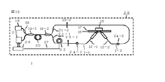
- FIG. 1 is a diagram for explaining a mode matching unit according to an embodiment of the present invention. That is, a relatively small core diameter / high NA polarization-maintaining optical fiber 1 as a first optical fiber is heated in the vicinity of the exit portion, that is, in the vicinity of the end portion to form a so-called core expansion optical fiber that expands the core portion.
- the end of the storage optical fiber 2 was connected and reinforced by the mode matching unit 3.
- the insertion loss of the mode matching section from the small core diameter / high NA polarization maintaining optical fiber 1 to the large core diameter / low NA polarization maintaining optical fiber 2 is as small as 0.1 dB. It was 8 dB.
- Reference numeral 4 denotes a connection portion between the first optical fiber 1 and the second optical fiber 2 including the mode matching portion 3, and this portion is also referred to as a mode matching portion in the following.
- FIG. 2 is a diagram for explaining the mode matching unit 4 used in the present embodiment.
- the mode matching unit 3 and the mode matching unit 4 include at least an end part of the first optical fiber which is a core expansion optical fiber and an end part of the second optical fiber connected thereto.
- the configuration includes the end portions of the first optical fiber and the second optical fiber, the mode matching section 3 and the mode matching section 4 in the present invention are not limited to this, and many Is possible.
- the end of the second optical fiber connected to the first optical fiber is extended by heating, for example, the vicinity of the end of the second optical fiber, and the end of the second optical fiber.
- the core diameter in the vicinity of the portion can be formed so as to gradually decrease toward the side connected to the first optical fiber, and it can be connected to the first optical fiber.
- the end portion of the first optical fiber is processed into the core expanded fiber, and the second optical fiber
- the connection loss due to processing errors can be further reduced.
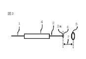
- FIG. 3 is a diagram for explaining the production of collimated light from the mode matching unit used in this embodiment.
- the end surface 2 a of the second optical fiber 2 is at the focal position 6 of the lens 5.
- an arrow with a reference numeral 7 is a line indicating the focal length of the lens 5.
- FIG. 4 is a diagram for explaining the production of defocused light from the mode matching unit used in the present embodiment.
- the end face 2 a of the optical fiber 2 is arranged at a position farther from the lens than the focal position 6 of the lens 5.
- the polarizer of the polarization conversion optical system, the Faraday element (Faraday rotator), and the quarter wave plate are located behind the lens as viewed from the tip of the optical fiber. Since it is necessary to dispose the lens, it is necessary to physically increase the distance between the lenses. Further, when the focal length of the lens was increased to 2.75 mm, the biological transmission loss could not be reduced to 70 dB or less when the distance between the lenses was 2 mm.
- a ring optical path of a ring interference system is used, the specimen is arranged in the middle of the ring optical path, and the optical path of the signal light
- An optical fiber terminal in the middle of one ring optical path and an optical fiber terminal in the middle of the other ring optical path, which are arranged to face each other with a sample interposed therebetween, are each used as a polarization conversion optical system, and the polarization conversion optical system uses a polarization plane rotating element. It is configured as a nonreciprocal optical system.
- the polarization plane rotation element when a polarization beam as signal light is incident from one side of the polarization plane rotation element, the polarization plane of the signal light is rotated clockwise or counterclockwise toward the traveling direction of the signal light.
- the polarized light beam is incident as signal light from the other side of the polarization plane rotating element, the polarization plane of the signal light is incident from the one side toward the traveling direction of the signal light. It is preferable to use a polarization plane rotating element that acts so as to be rotated by a predetermined angle in the opposite direction to the case where it is made.
- the polarization as the clockwise signal light and the polarization as the counterclockwise signal light are propagated in the ring optical path of the ring interference system, and as described in detail below, the ring interference system
- the optical fiber part of the ring optical path propagates the same optical fiber as right-handed light and left-handed light respectively in the same polarization mode with the same polarization as right-handed signal light and left-handed signal light
- the specimen part has The light beams are propagated as right-handed light and left-handed light in the polarization states orthogonal to each other, and the optical rotation of the specimen can be detected with high accuracy by utilizing each configuration of the present invention.
- FIG. 5 is a diagram showing the production of collimated circularly polarized light from the mode matching unit used in the present embodiment.
- the end face 2 a of the optical fiber 2 is at the focal position 6 of the lens 5.
- reference numeral 11 denotes a polarization conversion collimator including a mode matching unit.
- the linearly polarized outgoing light of the large core diameter / low NA polarization-preserving optical fiber 2 that is the pigtail of the mode matching unit 4 is collimated by the lens 5 as signal light, and in turn, a polarizer (polarizing plate) 8, It is circularly polarized through a Faraday rotator 9 as a polarization plane rotator and a quarter-wave plate 10.
- FIG. 6 is a diagram showing that defocused circularly polarized light is generated from the mode matching unit used in the present embodiment.
- the end surface 2 a of the optical fiber 2 is on the opposite side of the lens by 0.7 mm from the focal position 6 of the lens 5 (that is, a position far from the lens).
- reference numeral 12 denotes a defocus polarization conversion optical system including a mode matching unit.
- the polarizer 8, the Faraday element 9, and the quarter wave plate 10 are between the lens 5 and the end face 2a of the second optical fiber 2, but the focal length of the lens to be used and the degree of defocusing. 5, the rear of the lens 5, that is, the polarizer 8, the Faraday rotator 9, and the quarter wave plate 10 of FIG. 6 are opposite to the end face 2 a of the optical fiber 2 of the lens 5. It can also be arranged on the side.
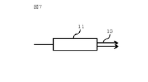
- FIG. 7 conceptually shows a beam emitted from the circularly polarized collimator including the mode matching unit used in this embodiment
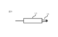
- FIG. 8 shows the circularly polarized light including the mode matching unit used in this embodiment. It is the figure which showed notionally the beam radiate
- a beam 13 emitted from a polarization conversion collimator (mode-matching collimated polarization conversion optical system) 11 including a mode matching unit is collimated circularly polarized light that is a parallel beam, and the specimen (FIG. 7) arranged in its traveling direction. so that the incident on the Shimese not).
- a beam 14 emitted from a defocus polarization conversion optical system (mode matching defocus polarization conversion optical system) 12 including a mode matching unit is defocused circularly polarized light that is a focused beam, and is arranged in the traveling direction thereof. Is incident on the specimen (not shown), and is collected near the exit end of the specimen.
- FIG. 9 shows an optical system in which the specimen 15 is inserted between the opposed mode matching collimated polarization conversion optical systems 11-1 and 11-2 as an embodiment of the present invention.
- FIG. 10 shows an optical system in which the specimen 15 is inserted between the opposed mode matching defocus polarization conversion optical systems 12-1 and 12-2 as an embodiment of the present invention.
- the insertion loss is smaller in the opposed mode matching collimated polarization conversion optical system of FIG.
- the counter mode matching defocus polarization conversion optical system in FIG. 10 is more suitable than the counter mode matching collimation polarization conversion optical system in FIG.
- the insertion loss is less about 1000 times (30 dB). Simulation technique that can explain the experimental results has not been commercialized.
- the polarizer 8, the Faraday rotator 9, and the quarter-wave plate 10 were made as thin as possible with the optical system shown in FIG. 6 and bonded together and placed between the end face of the optical fiber and the lens. Note that circularly polarized light beams that are orthogonal to each other enter the living body from the opposed defocus polarization conversion optical systems 12-1 and 12-2 including the mode matching unit in FIG.
- the opposite polarized light is coupled to the opposite polarization plane preserving optical fiber via the opposite defocus polarization conversion optical system to the same polarization axis as the incident linearly polarized light.
- the intrinsic polarization axis orientation of the quarter-wave plate facing the intrinsic polarization axis orientation of the wavefront-preserving optical fiber was adjusted.
- FIG. 11 illustrates a coupling optical system that irradiates a light scattering specimen obliquely with signal light using defocus polarization conversion optical systems 12-1 and 12-2 including a mode matching unit as an example of this embodiment.
- FIG. 11 illustrates a coupling optical system that irradiates a light scattering specimen obliquely with signal light using defocus polarization conversion optical systems 12-1 and 12-2 including a mode matching unit as an example of this embodiment.
- Figure 11 is a reflection system against 10 is transparent system.
- Reference numeral 16 is a quartz glass plate
- 17 is a quarter-wave plate.
- the phase of the light reflected on the surface of the living body or in the living body is reversed, so if there is no phase plate, the incident light and the reflected light are orthogonally polarized to the living body and the phase difference is canceled and the phase difference due to the optical rotation of the living body. Cannot be measured. Since the same circularly polarized light as the incident light is reflected by placing the phase plate between the living body (in this case, a kind of mirror) and the incident light, the defocus optical system 12 including the mode matching unit including the polarization state is reflected. The bonds -1 and 12-2 can be taken. Note that the measurement system of FIG. 11 does not use a metal plate, and the principle is different from that of a conventional SPR (surface plasmon resonance).
- SPR surface plasmon resonance
- FIG. 12 shows a coupling optical system in which a light scattering specimen is sandwiched by an opposed defocus polarization conversion optical system including a mode matching unit as an example of the embodiment shown in FIG.
- a coupling optical system in which a light scattering specimen is sandwiched by an opposed defocus polarization conversion optical system including a mode matching unit as an example of the embodiment shown in FIG.
- it is installed in a ring optical path including wavefront-preserving optical fibers 21-1 and 21-2 and measures the optical rotation of scattered light and reflected light from the surface and inside of the light scattering specimen 15.
- it is a configuration diagram of a main portion 28 of the optical rotation measurement device.
- the light source 18 is an SLD (Super Luminescent Diode) having a wavelength of 1060 nm, and its output is a first directional coupler (coupler) 19-1, an optical fiber polarizer 20, and a second directional coupler (coupler).
- the second coupler 19-2 branches to a small core diameter high NA polarization plane preserving optical fiber 21-1 and a small core diameter high NA polarization plane preserving optical fiber 21-2.
- the left and right linearly polarized light 23-1 and 23-2 that propagate through the ring optical path are generated.
- the first directional coupler (coupler) 19-1 can be replaced with a polarization-maintaining optical circulator.
- Reference numeral 22 denotes an optical phase modulator in which a small core diameter high NA polarization-maintaining optical fiber 21-1 of about 1 m is wound around a cylinder type PZT (lead zirconate titanate) element.
- the left and right light that circulates in the ring optical path is connected to defocus polarization conversion optical systems 12-1 and 12-2 including mode matching sections by splices 24-1 and 24-2, respectively.
- the light emitted from the specimen 15 propagates through the opposing defocus polarization conversion optical systems 12-1 and 12-2, and is received through the second coupler 19-2, the optical fiber polarizer 20, and the first coupler 19-1.
- the signal is converted into an electric signal by the device 25, and the signal processing unit 26 obtains the phase difference between the left and right light depending on the optical rotation of the light scattering specimen 15 by calculation.
- a 20 KHz sinusoidal modulation signal 27 is applied from the signal processing unit 26 to the optical phase modulator 22.
- the signal processing in FIG. 12 employs the method used in the phase modulation type optical fiber gyro described in Non-Patent Document 2.
- phase modulation is performed at 20 KHz
- a 40 KHz component that is a second harmonic and an 80 KHz component that is a fourth harmonic are output from the ring interference system in addition to the fundamental wave of 20 KHz.
- the phase difference between the left and right light propagating in the ring optical path is obtained. Since the ratio of the second harmonic and the fourth harmonic is proportional to the degree of phase modulation, it is controlled to be constant.
- the ring optical path of the ring interference system mainly includes polarization-maintaining optical fibers 21-1 and 21-2 that occupy most of the loop, and a defocus polarization conversion optical system 12-1 that is an embodiment of the present invention. 12-2 and a light scattering specimen 15.
- the light propagating around the left and right only propagates in the right and left circularly polarized light only in the portion of the light scattering sample 15, and the other polarization plane preserving optical fiber portions are Propagating in the same intrinsic polarization mode of the polarization-maintaining optical fiber.
- the other polarization plane preserving optical fiber portions are Propagating in the same intrinsic polarization mode of the polarization-maintaining optical fiber.
- it is known that linearly polarized light is decomposed into left and right circularly polarized light, and the direction of polarized light changes by ⁇ when a phase difference of 2 ⁇ occurs between the left and right circularly polarized light.
- the phase difference of the left and right circularly polarized light of the light scattering specimen 15 can be measured, its optical rotation can be measured.
- the thickness of the skin of the subject was about 1.5mm.
- the transmission loss of light in this portion itself is about 0.5 dB.
- a polarization maintaining optical fiber for communication with a wavelength of 1550 nm is used.
- the insertion loss was about 65 to 70 dB.
- the focal length of the lens is selected (0.7 mm), and the position of the optical fiber tip is 0.2 to
- the loss was 40 dB, which was 30 dB or more lower than the above example.
- the loss level of the optical interference system in this experiment was as follows.
- Light source output 10 mW (polarization plane preserving optical fiber output)
- Received power 50nW
- a silicon APD Alvalanche photodiode having a 100 KHz bandwidth and a minimum receiving sensitivity of 5 pW was used as the light receiver.
- the measurement time was 10 seconds, and the phase difference of the left and right circularly polarized light propagating through the finger folds could be measured with a sufficient signal-to-noise ratio.
- the light receiving level was adjusted to the same level as that in the case of the sample using the variable optical attenuator VOA 33 arranged on the input side as a reference when there is no sample.
- a refractive index matching agent was applied to the folds of the finger to suppress reflection loss.
- tip of a counter polarization conversion optical system was used.
- the phase difference was measured while shifting the measurement site in a direction perpendicular to the optical axis. As a result, to obtain a result that the phase difference changes depending on the site.
- Data related to blood glucose level can be obtained by repeating measurement for an actual diabetic patient. It is possible to measure a pulse by arranging a multimode optical fiber in parallel with a polarization-maintaining optical fiber for optical rotation measurement according to the present invention in the vicinity of a region to be measured, and measuring a variation in its insertion loss. it can.
- phase difference of the left and right circularly polarized light propagating in both directions in the ring optical path in the measurement system of FIG. 12 was monitored before and after the meal, the phase difference clearly changed after the meal. From this, it is considered that could be detected sugar contained in body fluids.
- FIG. 13 shows the coupling optical system shown in FIG. 11 that irradiates the light scattering sample 15 from the oblique direction using the mode-matching opposed defocus polarization conversion optical system as the second embodiment according to the present invention.
- a mirror is placed on the specimen portion in advance, and the axes are aligned so that the coupling between the defocus polarization conversion optical systems 12-1 and 12-2 can be achieved with the required accuracy. It was. Thereafter, the finger was placed on the quarter-wave plate 17 and the optical rotation included in the reflected light and scattered light from the living body was measured. Actually, a refractive index matching agent was used between the quarter-wave plate and the finger.
- the phase difference was measured while shifting the measurement site on the quarter-wave plate plane. As a result, to obtain a result that the phase difference changes depending on the site. This was interpreted as a difference between when the beam passed through the blood vessel and when it did not.
- Data related to the blood glucose level is created by repeating the measurement for an actual diabetic patient, a correspondence table between the measurement data and, for example, the blood glucose level is created, and input to the storage portion of the signal processing circuit 26, for example.
- the measurement results can be displayed.
- the signal detection synchronized with the pulse there is also a method of periodically changing the thickness of the living body by periodically pressing the portion sandwiching the living body and detecting a periodic signal synchronized with the cycle. It is valid.
- a signal for periodically changing the pulse and the thickness of the living body can be used in combination.
- At least one of the one single-mode optical fiber and the other single-mode optical fiber has an output lens at the tip (this output lens is a left-right signal light in a ring interference system).
- this output lens is a left-right signal light in a ring interference system.
- an output side optical fiber with respect to one signal light of the both directions of light for example, counterclockwise light
- at least one of the end faces of the single mode optical fiber having the output lens is an optical system that is not at the focal position of the output lens. It is characterized by constituting a focus polarization conversion optical system.
- FIG. 14 is a diagram for explaining the measurement method in the main part 28 of the optical rotation measuring apparatus as the third embodiment according to the present invention.
- the beam emitted from the defocus polarization conversion optical system 12-1 is the object to be measured. It is a figure explaining the example of the method of observing which part of the sample 15 which is which is irradiated.
- laser light from the HeNe laser 30 is incident as a visible laser from the other incident end of the second coupler 19-2 in FIG. 14, and the half mirror 31 is placed in front of the specimen 15,
- the microscope 32 was used to observe which part of the specimen 15 was irradiated with the beam emitted from the defocus polarization conversion optical system 12-1.
- the specimen 15 was a living body, the blood vessel portion could be observed by applying permeable oil.
- the HeNe laser was turned off and the microscope and the half mirror were removed. As a result, the optical rotation and the positional relationship between the blood vessels of the living body became clear.
- a polarization-preserving optical fiber having a core diameter of 30 ⁇ m and a low NA (0.07) having a light source wavelength of 1060 nm was used.
- the inventor changes the core diameter of the polarization-preserving optical fiber when the living body is sandwiched between the polarization conversion optical systems facing each other in the same wavelength band to 7 ⁇ m, 20 ⁇ m, and 30 ⁇ m, and changes the core diameter dependency of the transmission loss. Examined.
- the wavelength band of the light source is set to 1300 nm or more
- the core diameter can be made 40 ⁇ m with the same NA, and the biological transmission loss can be further reduced by 10 dB or more.
- the loss of the Faraday element (garnet) used in the polarization conversion optical system was about 5 dB when using an SLD with a wavelength of 1060 nm, but is so small that it is almost negligible at a wavelength of 1300 nm.
- the core diameter can be increased, but in the 1550 nm band, it is affected by absorption loss of moisture contained in the living body.
- the wavelength becomes longer, it becomes more susceptible to loss due to bending of the optical fiber.
- the inventor concludes that a 1300 nm-band broadband light source and a corresponding large core diameter / low NA polarization-preserving optical fiber can be used to realize a non-invasive optical rotation measuring device with the highest accuracy in defocus coupling system conditions. did.
- the loss level of the optical interference system in this experiment was as follows.
- Light source output 10 mW (polarization plane preserving optical fiber output)
- Received power 50nm
- a silicon APD having a 100 KHz bandwidth and a minimum receiving sensitivity of 5 pW was used as the light receiver.
- the average measurement time was 10 seconds, and the phase difference between the left and right circularly polarized light propagating in the control blood could be measured with a sufficient signal-to-noise ratio.
- the light receiving level was adjusted to the same level as that in the case of the sample using the variable optical attenuator VOA 33 arranged on the input side as a reference when there is no sample.
- the insertion loss was almost independent of blood thickness. That is, the insertion loss was about 40 dB even when the thickness was 0.1 mm, but it was 45.5 dB even when the thickness was 1 mm and 45 dB. This is thought to be due to multiple internal reflections in the blood.
- the angle of rotation of the healthy person with glucose is 0.0005 degrees.
- the phase difference measured by the ring interference system is 0.001 degree, which is the second growth.
- the length of the polarization-maintaining optical fiber other than the polarization conversion optical system in the ring optical path of the ring interference system used in the experiment was 400 m.
- the sensitivity of the minimum phase measurement when using a normal optical fiber ring interference system except for the polarization conversion optical system facing the ring interference system was 0.00005 degrees. This was confirmed from the variation in the measured values when the rotational angular velocity of the earth was measured with this ring interference system. Therefore, it can be said that the optical rotation of whole blood could be measured with sufficiently high accuracy.
- the defocused optical rotation measurement device including the mode matching unit, the defocus polarization conversion optical system including the mode matching unit, and the optical rotation measurement in the optical rotation measurement system using the optical system according to the embodiments of each invention
- each of the configurations of the embodiment uses a defocused optical rotation measuring device including a mode matching unit, a defocus polarization conversion optical system including a mode matching unit, and the optical system. Even if it is used in the optical rotation measurement method in the optical rotation measurement system, the effects of the respective embodiments can be exhibited, and not only the similar effects can be exhibited even if they are combined in various ways.
- the embodiment is not limited to this, and many variations are possible based on the technical idea of the present invention.
- non-invasive blood glucose level measurement that has not been realized by the present invention can be performed.
- diabetic patients can be freed from the trouble of collecting blood several times a day, and the number of diabetic patients currently increasing worldwide by utilizing the blood glucose level measuring device of the present invention in a preventive and conservative manner.
- the number can be reduced and the cost required for the treatment can be greatly reduced.
- the present invention can be used not only in the medical field and the nursing field but also in a wide range of fields such as the health device field, the pharmaceutical field, the food field, and the agricultural field.
Landscapes
- Health & Medical Sciences (AREA)
- Life Sciences & Earth Sciences (AREA)
- Physics & Mathematics (AREA)
- Pathology (AREA)
- General Health & Medical Sciences (AREA)
- Surgery (AREA)
- Veterinary Medicine (AREA)
- Engineering & Computer Science (AREA)
- Biomedical Technology (AREA)
- Heart & Thoracic Surgery (AREA)
- Medical Informatics (AREA)
- Molecular Biology (AREA)
- Optics & Photonics (AREA)
- Animal Behavior & Ethology (AREA)
- Biophysics (AREA)
- Public Health (AREA)
- Spectroscopy & Molecular Physics (AREA)
- Chemical & Material Sciences (AREA)
- Analytical Chemistry (AREA)
- Biochemistry (AREA)
- General Physics & Mathematics (AREA)
- Immunology (AREA)
- Emergency Medicine (AREA)
- Investigating Or Analysing Materials By Optical Means (AREA)
Abstract
【課題】採血した血液や生体のグルコース濃度を、試薬に頼らずに、医療現場で実際に使用できるような高い精度でリアルタイムに測定することができて、かつ、使い易い旋光度測定装置を提供する。 【解決手段】光ファイバリング干渉系中に旋光度測定用検体を挟んだ非相反偏光変換光学系を挿入し、非相反偏光変換光学系の入出力光ファイバには伝送部としての小コア径・高NAシングルモード光ファイバに入出力部としての大コア径・低NAシングルモード光ファイバをモード整合部を介して接続したものを用い、光ファイバ端面はレンズの焦点に置かずにデフォーカスにした構成を取り入れて課題を解決した。
Description
本発明は、採血した血液、血清、生体などのような光散乱検体の旋光度を偏光変換光学系を用いて測定する旋光度測定装置および旋光度測定に用いることができる偏光変換光学系ならびにその偏光変換光学系を用いた旋光度測定システムにおける旋光度測定方法(以下、旋光度測定システムにおける旋光度測定方法を単に旋光度測定方法という)に関し、例えば、モード整合部とデフォーカス偏光変換光学系を用いて旋光度被測定検体の糖質の濃度を測定することができるようにし、人の血液、血清、指、耳、皮膚などにレーザ光を照射し、その透過光および/または反射光を測定して旋光度被測定用検体の糖質成分濃度を高い測定精度で測定できるようにした旋光度測定装置および旋光度測定に用いることができる光ファイバ光学系である偏光変換光学系ならびにその光学系を用いた旋光度測定方法に関するものである。
血液中のグルコース濃度の測定方法として試みられている第1の方法は、たとえば特許文献1に記載があるような、指などの生体の一部に赤外レーザ光を照射し、血管からの散乱光を分光し血液に含まれるグルコース濃度を測定するものである。これはグルコース濃度に比例して散乱光が低減することを利用している。しかし、この方法は散乱光の光強度が温度や皮膚の水分や油成分などに依存するという問題があり、広く普及していない。
第2の方法は、たとえば非特許文献1および特許文献2などに記載されているように、互いに直交する偏光成分を旋光物質中を伝搬させてその複屈折率をオープンループで計測するものである。しかし、この方法では健常者の血糖値レベルである0.1g/dL(デシリットル)程度で厚さが10mm程度のグルコース濃度を測定すると誤差が大きく、光の散乱が大きい血液や指などの生体ではグルコース濃度を全く測定できない。
第3の方法は、特許文献3に記載されている複屈折率測定装置で測定する方法である。この方法は本発明と同じく偏波面保存光ファイバからなるリング干渉計のリング光路の中に対向コリメータ光学系を設け、検体内に平行ビームを伝搬させ、左右両回り光の位相差を測定することによって検体の旋光度を計測するものである。この方法では厚さ10mm程度のガラス製セルに入れたグルコースで健常者の血糖値レベルである0.1g/dLを十分な精度で測定できる。
しかし上記第3の方法はいわゆる光ファイバジャイロのリング光路の中に検体を置き、それに両方向からコリメータ光を入射させるものであるが、検体がたとえば人の親指と人差し指の付け根のひだ部の場合には、その挿入損失が60dB以上となり、受光レベルが受光器の感度以下になってしまい、検体に照射した左右両回り光の位相差を測定できなかった。この原因は、従来の偏波面保存光ファイバのコア直径が信号光の波長が800nm~1500nm用の場合、それぞれ4~10μmと小さいため、指のひだ部における光の散乱光を十分な結合効率で受光できないためであった。
以上のことからもわかることであるが、これまで採血した血液や生体のグルコース濃度を高精度に測定する光学的な測定装置の開発が多く試みられてきた。しかし、採血した血液や生体のグルコース濃度を高精度で測定することは極めて難しく、果物の糖度測定には用いることができるものの、採血した血液や生体のグルコース濃度の測定に使える測定器はまだ実現されておらず、採血した血液や生体のグルコース濃度の測定は試薬を用いた化学的な手法に頼らざるを得ないのが現状である。
横田 正幸他、「鉛ガラスファイバ偏光変調器を用いたグルコースセンサー」、第31回光波センシング技術研究会LST31-8,PP.51-56,2003年8月
梶岡、於保、「光ファイバジャイロの開発」、第3回光波センシング技術研究会、LST3-9,PP.55-62,1989年6月
以上述べたように現在までに採血した血液や生体のグルコース濃度を高精度に測定する光学的な測定装置は実用化されていない。その理由は、血液や生体にレーザ光を入射させたときに生体内で生じる散乱が非常に大きいため、検出される受光パワーが非常に小さくなり、グルコース濃度を高い精度で測定できなかったためである。
本発明は以上のような状況に鑑みてなされたもので、本発明が解決しようとする課題は、採血した血液や生体のグルコース濃度を、試薬に頼らずに、医療現場で実際に使用できるような高い精度でリアルタイムに測定することができて、かつ、使い易い旋光度測定装置、および、旋光度測定に用いることができる新規な偏光変換光学系とそれを用いた旋光度測定方法を提供することにある。
先端にレンズを配置した光ファイバを被測定対象(検体)を挟んで信号光の光路上で対向させて配置し、一方の光ファイバから他方の光ファイバに光結合させる光ファイバ光学系における結合損失を少なくするには、対向する各光ファイバをその端面がレンズの焦点位置にあるコリメータ光学系にするのがよいというのが衆知の技術思想である。しかし、本発明の発明者の検討結果によると、この方法では本発明の課題を解決することができない。
本発明は、従来の技術思想とは異なり、光ファイバの端面をレンズの焦点位置からずらして配置する全く新しい技術思想のデフォーカス偏光変換光学系を用いることによって課題を解決できることを見出した。さらに、モード整合部を偏光変換光学系に取り入れて、生体などの散乱体を光ファイバで挟んだ光学系の結合損失を従来では期待できなかったような低損失で実現し、課題を解決した。以下、本発明の例を具体的に説明する。
課題を解決するためになされた本発明の例としての第1の発明(以下、発明1という)は、先端部にレンズが配置されている光ファイバを信号光の光路において旋光度測定用検体(以下、検体という)を挟んで対向させて配置し、前記光ファイバから出射される信号光を前記検体に照射し、前記検体の旋光度に関する測定を行う旋光度測定装置において、対向させて配置されている前記先端部にレンズが配置されている光ファイバの少なくとも一方はコア径の異なる第1の光ファイバと第2の光ファイバをモード整合部を介して接続したシングルモード光ファイバであり、相対的に前記第1の光ファイバは小コア径・高NA(ここで、NAは開口数を意味する)シングルモード光ファイバであり、前記第2の光ファイバは大コア径・低NAシングルモード光ファイバであり、前記第1の光ファイバと第2の光ファイバをモード整合部を介して接続したシングルモード光ファイバは前記第2の光ファイバが前記第1の光ファイバよりも光路上で前記検体に近い側に配置されており、前記対向させて配置された前記先端部にレンズが配置されている光ファイバの前記検体に近い側の端面近傍に前記レンズが出力用および/または入力用のレンズ(以下、出力部レンズという)として信号光の光路において配置されており、前記対向させて配置された先端部にレンズが配置されている光ファイバの少なくとも一方は、信号光の光路上でその端面が当該出力部レンズの焦点位置から外れた位置にあり、先端部にレンズが配置されている一方の光ファイバの端面から出射される信号光を当該出力部レンズを経て前記検体に入射させ、前記検体を透過した信号光および/または前記検体によって反射された信号光を先端部にレンズが配置されている他方の光ファイバの端面に入射させるとともに、先端部にレンズが配置されている前記他方の光ファイバの端面から出射される信号光を当該出力部レンズを経て前記検体に入射させ、前記検体を透過した信号光および/または前記検体によって反射された信号光を先端部にレンズが配置されている前記一方の光ファイバの端面に入射させて、前記検体の旋光度に関連する光学情報を測定することができることを特徴とするモード整合部を含むデフォーカスされた旋光度測定装置の発明である。
本発明について詳細に後述するが、本発明の旋光度測定装置および旋光度測定方法に用いて顕著な効果を発揮する偏光変換光学系は、光ファイバにモード整合部を用いて前記検体の旋光度に関連する光学情報の測定を高めたこと、デフォーカス偏光変換光学系を用いて前記検体の旋光度に関連する光学情報の測定を高めたことに特筆すべき特徴がある。たとえば、採取した血液の旋光度に関連する光学情報の測定の場合、光ファイバにモード整合部を用いたことと偏光変換光学系をデフォーカス光学系にすることはいずれも前記光学情報の測定精度を高めることができる。そして、本発明は、偏光変換光学系として、光ファイバにモード整合部を用いることと偏光変換光学系をデフォーカス光学系にすることを併せて用いたモード整合部を含むデフォーカス偏光変換光学系を用いることにより、採血した血液のみならず、手の親指と人差し指の付け根のひだ部のような生体の旋光度に関連する光学情報を高精度で測定することを可能にしたものである。前記モード整合部を含むデフォーカス偏光変換光学系では、光ファイバの端部に出力部レンズを配置した光ファイバ光学系に偏光変換素子を配置した偏光変換光学系を従来のコリメート型にせずにデフォーカス型にしたことにより、従来の技術思想では想到し得なかったほど高い旋光度測定感度を実現することができたもので、本発明の効果をさらに大ならしめるために、前記先端部にレンズが配置されている光ファイバを、前記コア径の異なる第1の光ファイバと第2の光ファイバをモード整合部を介して接続したシングルモード光ファイバにしたことにより、特に顕著な効果を発揮する本発明の旋光度測定装置および旋光度測定方法を実現することができたものである。そして、前記偏光変換光学系の偏光面回転素子に、その一方の側から信号光としての偏光ビームを入射させたときには当該信号光の偏光面を当該信号光の進行方向に向かって時計回りまたは反時計回りに所定角度だけ回転させ、当該偏光面回転素子の他方の側から信号光として偏光ビームを入射させたときには当該信号光の偏光面を当該信号光の進行方向に向かって前記一方の側から入射させた場合とは逆方向に所定角度だけ回転させるように作用する非相反偏光面回転素子を用いたときに、本発明のモード整合技術とデフォーカス技術の効果が極めて高いものとなる。
なお、本発明において、信号光の光路において前記検体を挟んで対向配置された先端部にレンズが配置されている一方の大コア径・低NAシングルモード光ファイバと先端部にレンズが配置されている他方の大コア径・低NAシングルモード光ファイバとは異なる光ファイバである場合と同一の光ファイバである場合が可能である。
なお、本発明において、信号光の光路において前記検体を挟んで対向配置された先端部にレンズが配置されている一方の大コア径・低NAシングルモード光ファイバと先端部にレンズが配置されている他方の大コア径・低NAシングルモード光ファイバとは異なる光ファイバである場合と同一の光ファイバである場合が可能である。
発明1を展開してなされた本発明の他の例としての第2の発明(以下、発明2という)は、発明1に記載のモード整合部を含むデフォーカスされた旋光度測定装置において、前記一方の先端部にレンズが配置されている光ファイバの端面と前記他方の先端部にレンズが配置されている光ファイバの端面の少なくとも一方は、当該出力部レンズの焦点位置よりも当該出力部レンズから遠い位置で、当該光ファイバの端面の像が当該出力部レンズによって当該検体の出射面(すなわち、当該光ファイバから当該検体に入射した信号光が当該検体から出射する面)に結像するような位置にあることを特徴とするモード整合部を含むデフォーカスされた旋光度測定装置の発明である。
発明1、2を展開してなされた本発明の他の例としての第3の発明(以下、発明3という)は、発明1または2に記載のモード整合部を含むデフォーカスされた旋光度測定装置において、前記先端部にレンズが配置されている一方の光ファイバの端面と前記先端部にレンズが配置されている他方の光ファイバの端面の少なくとも一方は、当該出力部レンズの焦点位置よりも当該出力部レンズに近い位置にあることを特徴とするモード整合部を含むデフォーカスされた旋光度測定装置の発明である。
発明1~3を展開してなされた本発明の他の例としての第4の発明(以下、発明4という)は、発明1~3のいずれかに記載のモード整合部を含むデフォーカスされた旋光度測定装置において、前記モード整合部を含むデフォーカスされた旋光度測定装置は、前記先端部にレンズが配置されている光ファイバと前記光ファイバの一部を含んで構成され前記検体を挟んで配置される対向デフォーカス偏光変換光学系と前記検体とでリング光干渉系のリング光路を構成しており、前記リング光路を両方向に伝搬する光の位相差を測定することによって前記検体の旋光度を測定することができることを特徴とするモード整合部を含むデフォーカスされた旋光度測定装置の発明である。
発明4を展開してなされた本発明の他の例としての第5の発明(以下、発明5という)は、発明4に記載のモード整合部を含むデフォーカスされた旋光度測定装置において、前記モード整合部を含むデフォーカスされた旋光度測定装置は、リング干渉系のリング光路に右回り信号光としての偏光と左回り信号光としての偏光を伝搬させ、リング干渉系のリング光路の光ファイバ部分は右回り信号光としての偏光と左回り信号光としての偏光を同一の固有偏光モードで同じ光ファイバをそれぞれ右回り信号光と左回り信号光として伝搬させ、前記検体部分は互いに直交する偏光状態でそれぞれ右回り信号光と左回り信号光として信号光を伝搬させるようにリング光路が構成されていることを特徴とするモード整合部を含むデフォーカスされた旋光度測定装置の発明である。
発明1~5を展開してなされた本発明の他の例としての第6の発明(以下、発明6という)は、発明1~5のいずれかに記載のモード整合部を含む旋光度測定装置において、前記一方の先端部にレンズが配置されている光ファイバの端面と前記他方の先端部にレンズが配置されている光ファイバの端面の少なくとも一方は、当該出力部レンズの表面との距離が0.6mm以下であることを特徴とするモード整合部を含むデフォーカスされた旋光度測定装置の発明である。
発明1~6を展開してなされた本発明の他の例としての第7の発明(以下、発明7という)は、発明1~6のいずれかに記載のモード整合部を含むデフォーカスされた旋光度測定装置において、信号光の光路において前記検体を挟んで対向させて配置された一方の先端部にレンズが配置されている光ファイバと他方の先端部にレンズが配置されている光ファイバが同一のすなわち同じ光ファイバであることを特徴とするモード整合部を含むデフォーカスされた旋光度測定装置の発明である。
発明1~7を展開してなされた本発明の他の例としての第8の発明(以下、発明8という)は、発明1~7のいずれかに記載のモード整合部を含むデフォーカスされた旋光度測定装置において、前記先端部にレンズが配置されている光ファイバの先端部と当該出力部レンズとが相互に固定されていることを特徴とするモード整合部を含むデフォーカスされた旋光度測定装置の発明である。
発明1~8を展開してなされた本発明の他の例としての第9の発明(以下、発明9という)は、発明1~8のいずれかに記載のモード整合部を含むデフォーカスされた旋光度測定装置において、前記一方の先端部にレンズが配置されている光ファイバと前記他方の先端部にレンズが配置されている光ファイバの少なくとも一方は、当該先端部にレンズが配置されている光ファイバの端面と当該出力部レンズとの間にファラデー回転素子と4分の1波長板と偏光子のうちの少なくとも1つが配置されていることを特徴とするモード整合部を含むデフォーカスされた旋光度測定装置の発明である。
発明1~9を展開してなされた本発明の他の例としての第10の発明(以下、発明10という)は、発明1~9のいずれかに記載のモード整合部を含むデフォーカスされた旋光度測定装置において、前記先端部にレンズが配置されている一方の光ファイバと前記先端部にレンズが配置されている他方の光ファイバの少なくとも一方は、当該先端部にレンズが配置されている光ファイバの出力部レンズと前記検体との間にファラデー回転素子と4分の1波長板と偏光子のうちの少なくとも1つが配置されていることを特徴とするモード整合部を含むデフォーカスされた旋光度測定装置の発明である。
発明1~10を展開してなされた本発明の他の例としての第11の発明(以下、発明11という)は、発明1~10のいずれかに記載のモード整合部を含むデフォーカスされた旋光度測定装置において、前記モード整合部にコア拡大ファイバとコア縮小ファイバの一方または双方が用いられていることを特徴とするモード整合部を含むデフォーカスされた旋光度測定装置の発明である。
本発明のモード整合部を含むデフォーカスされた旋光度測定装置には、前記モード整合部にコア拡大ファイバとコア縮小ファイバの双方が用いることができる。
発明1~11を展開してなされた本発明の他の例としての第12の発明(以下、発明12という)は、発明1~11のいずれかに記載のモード整合部を含むデフォーカスされた旋光度測定装置において、光路と直角方向に前記検体及び/または前記偏光変換光学系をスキャンできる機構を有することを特徴とするモード整合部を含むデフォーカスされた旋光度測定装置の発明である。
発明1~12を展開してなされた本発明の他の例としての第13の発明(以下、発明13という)は、発明1~12のいずれかに記載のモード整合部を含むデフォーカスされた旋光度測定装置において、前記検体が生体の一部であり、前記旋光度測定装置は前記検体の旋光度に関連する光学情報を測定するのに、前記信号光の位相差の検出手段の一部として、生体の脈拍及び/または人為的に与えた測定部位の厚味などの当該生体の一部の寸法を周期的に変化させる信号と同期させて前記位相差を検出する手段を有することを特徴とするモード整合部を含むデフォーカスされた旋光度測定装置の発明である。
発明1~13を展開してなされた本発明の他の例としての第14の発明(以下、発明14という)は、発明1~13のいずれかに記載のモード整合部を含むデフォーカスされた旋光度測定装置において、前記検体が生体の一部であり、前記旋光度測定装置は前記検体の旋光度に関連する光学情報を測定する部分を挟む測定端子を有することを特徴とするモード整合部を含むデフォーカスされた旋光度測定装置の発明である。
発明1~14を展開してなされた本発明の他の例としての第15の発明(以下、発明15という)は、発明1~14のいずれかに記載のモード整合部を含むデフォーカスされた旋光度測定装置において、前記一方の先端部にレンズが配置されている光ファイバの出力部レンズと他方の先端部にレンズが配置されている光ファイバの出力部レンズとの距離を変更することができるレンズ間距離調整手段を有することを特徴とするモード整合部を含むデフォーカスされた旋光度測定装置の発明である。
発明1~15を展開してなされた本発明の他の例としての第16の発明(以下、発明16という)は、発明1~15のいずれかに記載のモード整合部を含むデフォーカスされた旋光度測定装置において、光源の波長が1300nm帯で、前記大コア径・低NA偏波面保存光ファイバのコア径が40μm、NAが0.06±0.01であることを特徴とするモード整合部を含むデフォーカスされた旋光度測定装置の発明である。
NAが0.05より小さくなると、光ファイバの曲げによる損失が大きくなる。また、0.07より大きくなると、出射光の広がりによる生体透過損失が大きくなる。
NAが0.05より小さくなると、光ファイバの曲げによる損失が大きくなる。また、0.07より大きくなると、出射光の広がりによる生体透過損失が大きくなる。
課題を解決するためになされた本発明の他の例としての第17の発明(以下、発明17という)は、先端部にレンズが配置されている光ファイバを信号光の光路において検体を挟んで対向させて配置し、前記光ファイバから出射される信号光を前記検体に照射し、前記検体の旋光度に関する測定を行う旋光度測定システムに用いることができる偏光変換光学系において、対向配置して用いることができる前記偏光変換光学系の少なくとも一方の前記先端部にレンズが配置されている光ファイバはコア径の異なる第1の光ファイバと第2の光ファイバをモード整合部を介して接続したシングルモード光ファイバであり、相対的に前記第1の光ファイバは小コア径・高NAシングルモード光ファイバで前記第2の光ファイバは大コア径・低NAシングルモード光ファイバであり、前記第1の光ファイバと第2の光ファイバをモード整合部を介して接続したシングルモード光ファイバは前記第2の光ファイバが前記第1の光ファイバよりも光路上で前記検体に近い側に配置できるように構成されており、前記先端部にレンズが配置されている光ファイバの前記検体に近い側の端面近傍に前記レンズが出力部レンズとして信号光の光路において配置されており、前記旋光度測定システムに対向させて配置用いる先端部にレンズが配置されている光ファイバの少なくとも一方は、信号光の光路上でその端面が当該出力部レンズの焦点位置から外れた位置にあり、先端部にレンズが配置されている一方の光ファイバの端面から出射される信号光を当該出力部レンズを経て前記検体に入射させ、前記検体を透過した信号光および/または前記検体によって反射された信号光を先端部に出力部レンズが配置されている他方の光ファイバの端面に入射させることができるように配置して前記旋光度測定システムに用いて前記検体の旋光度に関連する光学情報を測定するのに使用することができることを特徴とするモード整合部を含むデフォーカス偏光変換光学系の発明である。
発明17を展開してなされた本発明の他の例としての第18の発明(以下、発明18という)は、発明17に記載のモード整合部を含むデフォーカス偏光変換光学系において、前記旋光度測定システムに用いたときの前記先端部にレンズが配置されている一方の光ファイバの端面と前記先端部にレンズが配置されている他方の光ファイバの端面の少なくとも一方は、当該出力部レンズの焦点位置よりも当該出力部レンズから遠い位置で、当該光ファイバの端面の像が当該出力部レンズによって当該検体の出射面(すなわち、当該光ファイバから当該検体に入射した信号光が当該検体から出射する面)に結像するような位置にあることを特徴とするモード整合部を含むデフォーカス偏光変換光学系の発明である。
発明17、発明18を展開してなされた本発明の他の例としての第19の発明(以下、発明18という)は、発明17または18に記載のモード整合部を含むデフォーカス偏光変換光学系において、前記一方の先端部にレンズが配置されている光ファイバの端面と前記他方の先端部にレンズが配置されている光ファイバの端面の少なくとも一方は、当該出力部レンズの焦点位置よりも当該出力部レンズに近い位置にあることを特徴とするモード整合部を含むデフォーカス偏光変換光学系の発明である。
発明17~19を展開してなされた本発明の他の例としての第20の発明(以下、発明20という)は、発明17~19のいずれかに記載のモード整合部を含むデフォーカス偏光変換光学系において、前記モード整合部を含むデフォーカス偏光変換光学系は前先端部にレンズが配置されている光ファイバと前記先端部にレンズが配置されている光ファイバの一部を含んで構成される対向デフォーカス偏光変換光学系と前記検体とでリング光干渉系のリング光路を構成して前記検体の旋光度に関連する光学情報を測定するのに使用することができるデフォーカス偏光変換光学系であることを特徴とするモード整合部を含むデフォーカス偏光変換光学系の発明である。
発明20を展開してなされた本発明の他の例としての第21の発明(以下、発明21という)は、発明20に記載のモード整合部を含むデフォーカス偏光変換光学系において、前記リング干渉系のリング光路に右回り信号光としての偏光と左回り信号光としての偏光を伝搬させ、前記リング干渉系のリング光路の光ファイバ部分は右回り信号光としての偏光と左回り信号光としての偏光を同一の固有偏光モードで同じ光ファイバをそれぞれ右回り信号光と左回り信号光として伝搬させ、前記検体部分は右回り信号光としての偏光と左回り信号光としての偏光を互いに直交する偏光状態でそれぞれ右回り信号光と左回り信号光として伝搬させるように前記偏光変換光学系が構成されていることを特徴とするモード整合部を含むデフォーカス偏光変換光学系の発明である。
発明17~21を展開してなされた本発明の他の例としての第22の発明(以下、発明22という)は、発明17~21のいずれかに記載のモード整合部を含むデフォーカス偏光変換光学系において前記検体の旋光度に関連する光学情報を測定するのに対向配置して使用するときの前記先端部にレンズが配置されている一方の光ファイバの端面と前記先端部にレンズが配置されている他方の光ファイバの端面の少なくとも一方は、当該出力部レンズの表面との距離が0.6mm以下にして用いることができることを特徴とするモード整合部を含むデフォーカス偏光変換光学系の発明である。
発明17~22を展開してなされた本発明の他の例としての第23の発明(以下、発明23という)は、発明17~22のいずれかに記載のモード整合部を含むデフォーカス偏光変換光学系において、信号光の光路において前記検体を挟んで対向させて配置された先端部にレンズが配置されている一方の光ファイバと先端部にレンズが配置されている他方の光ファイバに同一のすなわち同じ光ファイバを用いることができることを特徴とするモード整合部を含むデフォーカス偏光変換光学系の発明である。
発明17~23を展開してなされた本発明の他の例としての第24の発明(以下、発明24という)は、発明17~23のいずれかに記載のモード整合部を含むデフォーカス偏光変換光学系において、前記先端部にレンズが配置されている光ファイバの先端部と当該出力部レンズとが相互に固定されていることを特徴とするモード整合部を含むデフォーカス偏光変換光学系の発明である。
発明17~24を展開してなされた本発明の他の例としての第25の発明(以下、発明25という)は、発明17~24のいずれかに記載のモード整合部を含むデフォーカス偏光変換光学系において、前記先端部にレンズが配置されている一方の光ファイバと前記先端部にレンズが配置されている他方の光ファイバの少なくとも一方は、当該光ファイバの端面と当該出力部レンズとの間にファラデー回転素子と4分の1波長板と偏光子のうちの少なくとも1つが配置されていることを特徴とするモード整合部を含むデフォーカス偏光変換光学系の発明である。
発明17~25を展開してなされた本発明の他の例としての第26の発明(以下、発明26という)は、発明17~25のいずれかに記載のモード整合部を含むデフォーカス旋光度測定装置において、前記先端部にレンズが配置されている一方の光ファイバと前記先端部にレンズが配置されている他方の光ファイバの少なくとも一方は、当該光ファイバの出力部レンズと前記検体との間にファラデー回転素子と4分の1波長板と偏光子のうちの少なくとも1つが配置されていることを特徴とするモード整合部を含むデフォーカス偏光変換光学系の発明である。
発明17~26を展開してなされた本発明の他の例としての第27の発明(以下、発明27という)は、発明17~26のいずれかに記載のモード整合部を含むデフォーカス偏光変換光学系において、前記モード整合部にコア拡大ファイバとコア縮小ファイバの一方または双方が用いられていることを特徴とするモード整合部を含むデフォーカス偏光変換光学系の発明である。
発明17~27を展開してなされた本発明の他の例としての第28の発明(以下、発明28という)は、発明17~27のいずれかに記載のモード整合部を含むデフォーカス偏光変換光学系において、光路と直角方向に前記検体及び/または前記偏光変換光学系をスキャンできる機構を有することを特徴とするモード整合部を含むデフォーカス偏光変換光学系の発明である。
発明17~28を展開してなされた本発明の他の例としての第29の発明(以下、発明29という)は、発明17~28のいずれかに記載のモード整合部を含むデフォーカス偏光変換光学系において、前記検体が生体の一部であり、前記デフォーカス偏光変換光学系は前記検体の旋光度に関連する光学情報を測定するのに、前記信号光の位相差の検出手段の一部として、生体の脈拍及び/または人為的に与えた測定部位の厚味などの当該生体の一部の寸法を周期的に変化させる信号と同期させて前記位相差を検出する手段を有することを特徴とするモード整合部を含むデフォーカス偏光変換光学系の発明である。
発明17~29を展開してなされた本発明の他の例としての第30の発明(以下、発明30という)は、発明17~29のいずれかに記載のモード整合部を含むデフォーカス偏光変換光学系において、前記検体が生体の一部であり、前記デフォーカス偏光変換光学系は前記検体の旋光度に関連する光学情報を測定する部分を挟む測定端子を有することを特徴とするモード整合部を含むデフォーカス偏光変換光学系の発明である。
発明17~30を展開してなされた本発明の他の例としての第31の発明(以下、発明31という)は、発明17~30のいずれかに記載のモード整合部を含むデフォーカス偏光変換光学系において、前記先端部にレンズが配置されている一方の光ファイバの出力部レンズと先端部にレンズが配置されている他方の光ファイバの出力部レンズとの距離を変更することができるレンズ間距離調整手段を有することを特徴とするモード整合部を含むデフォーカス偏光変換光学系の発明である。
発明17~31を展開してなされた本発明の他の例としての第32の発明(以下、発明32という)は、発明17~31のいずれかに記載のモード整合部を含むデフォーカス偏光変換光学系において、光源の波長が1300nm帯で、前記大コア径・低NA偏波面保存光ファイバのコア径が40μm、NAが0.06±0.01であることを特徴とするモード整合部を含むデフォーカス偏光変換光学系の発明である。
課題を解決するためになされた本発明の他の例としての第33の発明(以下、発明33という)は、先端部にレンズが配置されている光ファイバを信号光の光路において検体を挟んで対向させて配置した偏光変換光学系を用いた旋光度測定システムに用いて検体の旋光度を測定する旋光度測定方法(以下、た旋光度測定システムに用いて検体の旋光度を測定する旋光度測定方法を単に旋光度測定方法という)において、前記旋光度測定方法は、偏光変換光学系とリング干渉系を用意して旋光度測定システムを構成するか偏光変換光学系とリング干渉系を有する旋光度測定装置を旋光度測定システムとして用意する工程と、旋光度測定システムの前記偏光変換光学系に検体を装着する工程と、検体に右回り信号光と左回り信号光として入射させた互いに直交する偏光の信号光の検体に起因して生じる位相差を測定する工程を有しており、前記リング干渉系のリング光路が、対向配置されている前記先端部にレンズが配置された光ファイバと信号光の光路上で検体を挟んで対向配置された前記対向偏光変換光学系と検体を含んでおり、前記リング干渉系は、前記リング光路を両方向に伝搬する光の位相差を測定することによって前記検体の旋光度に関連する光学情報を測定することができる干渉系であり、対向配置されている少なくとも一方の前記先端部にレンズが配置されている光ファイバはコア径の異なる第1の光ファイバと第2の光ファイバをモード整合部を介して接続したシングルモード光ファイバであり、相対的に前記第1の光ファイバは小コア径・高NAシングルモード光ファイバで前記第2の光ファイバは大コア径・低NAシングルモード光ファイバであり、前記第1の光ファイバと第2の光ファイバをモード整合部を介して接続したシングルモード光ファイバは前記第2の光ファイバが前記第1の光ファイバよりも光路上で前記検体に近い側に配置されており、前記対向させて配置された先端部にレンズが配置されている光ファイバの前記検体に近い側の端面近傍に前記レンズが出力部レンズとして信号光の光路において配置されており、前記対向させて配置された前記光ファイバの少なくとも一方は、信号光の光路上でその端面が当該出力部レンズの焦点位置から外れた位置にあり、前記偏光変換光学系は、少なくとも、前記先端部にレンズが配置された光ファイバの一部と出力部レンズと前記光ファイバの端面と検体との間に配置された偏光面回転素子を有しており、前記偏光面回転素子は、当該偏光面回転素子の一方の側から信号光としての偏光ビームを入射させたときには当該信号光の偏光面を当該信号光の進行方向に向かって時計回りまたは反時計回りに所定角度だけ回転させ、当該偏光面回転素子の他方の側から信号光として偏光ビームを入射させたときには当該信号光の偏光面を当該信号光の進行方向に向かって前記一方の側から入射させた場合とは逆方向に所定角度だけ回転させるように作用する非相反偏光面回転素子であり、
前記対向偏光変換光学系は、対向配置された出力部レンズが配置されている一方の光ファイバの端面から出射される信号光を当該出力部レンズを経て前記検体に入射させ、前記検体を透過した信号光および/または前記検体によって反射された信号光を先端部に出力部レンズが配置されている他方の光ファイバの端面に入射させさせるとともに、前記他方の光ファイバの端面から出射される信号光を当該出力部レンズを経て前記検体に入射させ、前記検体を透過した信号光および/または前記検体によって反射された信号光を先端部に出力部レンズが配置されている前記一方の光ファイバの端面に入射させて、前記リング干渉系で前記検体の旋光度に関連する光学情報を測定することができるモード整合部を含むデフォーカス偏光変換光学系であることを特徴とする旋光度測定方法の発明である。
前記対向偏光変換光学系は、対向配置された出力部レンズが配置されている一方の光ファイバの端面から出射される信号光を当該出力部レンズを経て前記検体に入射させ、前記検体を透過した信号光および/または前記検体によって反射された信号光を先端部に出力部レンズが配置されている他方の光ファイバの端面に入射させさせるとともに、前記他方の光ファイバの端面から出射される信号光を当該出力部レンズを経て前記検体に入射させ、前記検体を透過した信号光および/または前記検体によって反射された信号光を先端部に出力部レンズが配置されている前記一方の光ファイバの端面に入射させて、前記リング干渉系で前記検体の旋光度に関連する光学情報を測定することができるモード整合部を含むデフォーカス偏光変換光学系であることを特徴とする旋光度測定方法の発明である。
発明33を展開してなされた本発明の他の例としての第34の発明(以下、発明34という)は、発明33に記載の旋光度測定方法において、前記先端部にレンズが配置されている一方の光ファイバの端面と前記他方の光ファイバの端面の少なくとも一方を、当該出力部レンズの焦点位置よりも当該出力部レンズから遠い位置で、当該光ファイバの端面の像が当該出力部レンズによって当該検体の出射面(すなわち、当該光ファイバから当該検体に入射した信号光が当該検体から出射する面)に結像するような位置に配置して旋光度に関連する光学情報を測定することを特徴とする旋光度測定方法の発明である。
発明33、34を展開してなされた本発明の他の例としての第35の発明(以下、発明35という)は、発明33または34に記載の旋光度測定方法において、対向配置された前記一方の光ファイバの端面と前記他方の光ファイバの端面の少なくとも一方を、当該出力部レンズの焦点位置よりも当該出力部レンズに近い位置に配置した偏光変換光学系を用いることを特徴とする旋光度測定方法の発明である。
発明33~35を展開してなされた本発明の他の例としての第36の発明(以下、発明36という)は、発明33~35のいずれかに記載の旋光度測定方法において、前記先端部にレンズが配置されている一方の光ファイバの端面と前記他方の光ファイバの端面の少なくとも一方を、当該出力部レンズの表面との距離が0.6mm以下になるように配置して旋光度に関連する光学情報を測定することを特徴とする旋光度測定方法の発明である。
発明33~36を展開してなされた本発明の他の例としての第37の発明(以下、発明37という)は、発明33~36のいずれかに記載の旋光度測定方法において、信号光の光路において前記検体を挟んで対向させて配置された光ファイバと他方の光ファイバが同一のすなわち同じ光ファイバであることを特徴とする旋光度測定方法の発明である。
発明33~37を展開してなされた本発明の他の例としての第38の発明(以下、発明38という)は、発明33~37のいずれかに記載の旋光度測定方法において、前記先端部にレンズが配置されている一方の光ファイバと前記他方の光ファイバの少なくとも一方は、当該光ファイバの端面と当該出力部レンズとの間に前記非相反偏光面回転素子としてのファラデー回転素子と4分の1波長板と偏光子のうちの少なくとも1つが配置されている光ファイバを用いて旋光度に関連する光学情報を測定することを特徴とする旋光度測定方法の発明である。
発明33~38を展開してなされた本発明の他の例としての第39の発明(以下、発明39という)は、発明33~38のいずれかに記載の旋光度測定方法において、前記先端部にレンズが配置されている一方の光ファイバと前記他方の光ファイバの少なくとも一方は、当該光ファイバの出力部レンズと前記検体との間に前記非相反偏光面回転素子としてのファラデー回転素子と4分の1波長板と偏光子のうちの少なくとも1つが配置されている光ファイバを用いて旋光度に関連する光学情報を測定することを特徴とする旋光度測定方法の発明である。
発明33~39を展開してなされた本発明の他の例としての第40の発明(以下、発明40という)は、発明33~39のいずれかに記載の旋光度測定方法において、前記モード整合部にコア拡大ファイバとコア縮小ファイバの一方または双方が用いられていることを特徴とする旋光度測定方法の発明である。
発明33~40を展開してなされた本発明の他の例としての第41の発明(以下、発明41という)は、発明33~40のいずれかに記載の旋光度測定方法において、前記リング干渉系のリング光路に右回り信号光としての偏光と左回り信号光としての偏光を伝搬させ、前記リング干渉系のリング光路の光ファイバ部分は右回り信号光としての偏光と左回り信号光としての偏光を同一の固有偏光モードで同じ光ファイバをそれぞれ右回り信号光と左回り信号光として伝搬させ、前記検体部分は右回り信号光としての偏光と左回り信号光としての偏光を互いに直交する偏光状態でそれぞれ右回り信号光と左回り信号光として伝搬させるように前記偏光変換光学系が構成されていることを特徴とする旋光度測定方法の発明である。
発明33~41を展開してなされた本発明の他の例としての第42の発明(以下、発明42という)は、発明33~41のいずれかに記載の旋光度測定方法において、光路と直角方向に前記検体及び/または前記偏光変換光学系をスキャンできる機構を用いることを特徴とする旋光度測定方法の発明である。
発明33~42を展開してなされた本発明の他の例としての第43の発明(以下、発明43という)は、発明33~42のいずれかに記載の旋光度測定方法において、前記検体が生体の一部であり、前記検体の旋光度に関連する光学情報を測定するのに、前記信号光の位相差の検出手段の一部として、生体の脈拍及び/または人為的に与えた測定部位の厚味などの当該生体の一部の寸法等の状態を周期的に変化させる信号と同期させて前記位相差を検出する手段を用いて旋光度に関連する光学情報を測定することを特徴とする旋光度測定方法の発明である。
発明33~43を展開してなされた本発明の他の例としての第44の発明(以下、発明44という)は、発明33~43のいずれかに記載の旋光度測定方法において、前記検体が生体の一部であり、前記偏光変換光学系に前記検体の旋光度に関連する光学情報を測定する部分を挟む測定端子を用いていることを特徴とする旋光度測定方法の発明である。
発明33~44を展開してなされた本発明の他の例としての第45の発明(以下、発明45という)は、発明33~44のいずれかに記載の旋光度測定方法において、前記一方の光ファイバの出力部レンズと他方の光ファイバの出力部レンズとの距離を変更する手段を用いることを特徴とする旋光度測定方法の発明である。
発明33~45を展開してなされた本発明の他の例としての第46の発明(以下、発明46という)は、発明33~45のいずれかに記載の旋光度測定方法において、光源の波長が1300nm帯で、前記大コア径・低NA偏波面保存光ファイバのコア径が40μm、NAが0.06±0.01である偏光変換光学系を用いることを特徴とする旋光度測定方法の発明である。
課題を解決するためになされた本発明の他の例としての第47の発明(以下、発明47という)は、先端部にレンズが配置されている光ファイバを信号光の光路において光散乱検体などの検体を挟んで対向配置し、前記先端部にレンズが配置されている一方の光ファイバの端面から出射される信号光を前記検体に入射させ、前記検体を透過した信号光及び/又は前記検体によって反射された信号光を先端部にレンズが配置されている他方の光ファイバの端面に入射させて前記検体の旋光度に関連する光学情報を測定することができる旋光度測定装置において、前記先端部にレンズが配置されている一方の光ファイバの前記検体に入射させる信号光の出力部及び/又は前記検体からの信号光(前記検体に入射した前記信号光が前記検体を透過した光及び/または前記検体により反射あるいは散乱された光)の入力部に配置されている出力部レンズと前記先端部にレンズが配置されている他方の光ファイバの出力部レンズの少なくとも一方は、当該光ファイバの端面が当該出力部レンズの焦点位置にないデフォーカスされた光ファイバ光学系を形成していることを特徴とするデフォーカスされた旋光度測定装置の発明である。
発明47を展開してなされた本発明の他の例としての第48の発明(以下、発明48という)は、発明47に記載のデフォーカスされた旋光度測定装置において、前記一方の先端部にレンズが配置されている光ファイバの端面と前記他方の先端部にレンズが配置されている光ファイバの端面の少なくとも一方は、当該出力部レンズの焦点位置よりも当該出力部レンズから遠い位置で、当該光ファイバの端面の像が当該出力部レンズによって当該検体の出射面(すなわち、当該光ファイバから当該検体に入射した信号光が当該検体から出射する面)に結像するような位置にあることを特徴とするデフォーカスされた旋光度測定装置の発明である。
発明47、48を展開してなされた本発明の他の例としての第49の発明(以下、発明49という)は、発明47または48に記載のデフォーカスされた旋光度測定装置において、前記先端部にレンズが配置されている一方の光ファイバの端面と前記先端部にレンズが配置されている他方の光ファイバの端面の少なくとも一方は、当該出力部レンズの焦点位置よりも当該出力部レンズに近い位置にあることを特徴とするデフォーカスされた旋光度測定装置の発明である。
課題を解決するためになされた本発明の他の例としての第50の発明(以下、発明50という)は、リング光路の構成要素である先端部にレンズが配置されている光ファイバを信号光の光路において検体を挟んで対向させて配置し、前記光ファイバから出射される信号光を前記検体に照射し、前記検体の旋光度に関する測定を行う旋光度測定装置において、前記先端部にレンズが配置されている光ファイバの少なくとも一方はコア径の異なる第1の光ファイバと第2の光ファイバをモード整合部を介して接続したシングルモード光ファイバであり、相対的に前記第1の光ファイバは小コア径・高NAシングルモード光ファイバで、前記第2の光ファイバは大コア径・低NAシングルモード光ファイバであり、前記第1の光ファイバと第2の光ファイバをモード整合部を介して接続したシングルモード光ファイバは前記第2の光ファイバが前記第1の光ファイバよりも光路上で前記検体に近い側に配置されており、前記対向させて配置された前記先端部にレンズが配置されている光ファイバの前記検体に近い側の端面近傍に前記レンズが出力部レンズとして信号光の光路において配置されており、信号光の光路上で前記検体を挟んで対向させて配置された前記先端部にレンズが配置されている光ファイバは、それぞれその端面と検体の間に、前記出力部レンズの他に、少なくとも非相反偏光面回転素子が配置された偏光変換光学系を形成しており、光路上で前記検体を挟んで対向配置された前記偏光変換光学系からは互いに直交する偏光が前記検体にそれぞれ右回り信号光と左回り信号光として入射するように構成されており、前記対向配置された偏光変換光学系の一方の偏光変換光学系である第1の偏光変換光学系の前記出力部レンズが配置されている光ファイバの端面からリング光路の右回り信号光あるいは左回り信号光として出射される信号光を当該出力部レンズを経て前記検体に入射させ、前記検体を透過した信号光および/または前記検体によって反射された信号光を前記対向配置された偏光変換光学系の他方の偏光変換光学系である第2の偏光変換光学系の前記先端部に出力部レンズが配置されている光ファイバの端面に入射させ、前記対向配置された偏光変換光学系の前記第2の偏光変換光学系の前記出力部レンズが配置されている光ファイバの端面からリング光路の左回り信号光あるいは右回り信号光として出射される信号光を当該出力部レンズを経て前記検体に入射させ、前記検体を透過した信号光および/または前記検体によって反射された信号光を前記対向配置された前記第1の偏光変換光学系の前記先端部に出力部レンズが配置されている光ファイバの端面に入射させて前記検体の旋光度に関連する光学情報を測定することができることを特徴とするモード整合部を含む旋光度測定装置の発明である。
発明50を展開してなされた本発明の他の例としての第51の発明(以下、発明51という)は、発明50に記載のモード整合部を含む旋光度測定装置において、信号光の光路において前記検体を挟んで対向させて配置された一方の光ファイバと他方の光ファイバが同一のすなわち同じ光ファイバであることを特徴とするモード整合部を含む旋光度測定装置の発明である。
課題を解決するためになされた本発明の他の例としての第52の発明(以下、発明52という)は、先端部にレンズが配置されている光ファイバを信号光の光路において検体を挟んで対向させて配置し、前記光ファイバから出射される信号光を前記検体に照射し、前記検体の旋光度に関する測定を行う旋光度測定システムに用いることができる偏光変換光学系において、対向配置して用いる前記偏光変換光学系の少なくとも一方の光ファイバの前記検体に近い側の端面近傍に前記レンズが出力部レンズとして信号光の光路において配置されており、前記対向させて配置された光ファイバの少なくとも一方は、信号光の光路上でその端面が当該出力部レンズの焦点位置から外れた位置にあり、出力部レンズが配置されている一方の光ファイバの端面から出射される信号光を当該出力部レンズを経て前記検体に入射させ、前記検体を透過した信号光および/または前記検体によって反射された信号光を先端部に出力部レンズが配置されている他方の光ファイバの端面に入射させて前記検体の旋光度に関連する光学情報を測定するのに使用することができることを特徴とするデフォーカス偏光変換光学系の発明である。
なお、発明50、51に記載の旋光度測定装置は、さらに発明1~16に記載の本発明の各構成要素を付加した発明を本発明として構成でき、また、発明52に記載の偏光変換光学系は、さらに発明17~32に記載の本発明の構成要素を付加した発明を本発明として構成できることは以下の説明からも明らかなことである。
また、先端部にレンズが配置されている光ファイバを信号光の光路において検体を挟んで対向させて配置し、前記光ファイバから出射される信号光を前記検体に照射し、前記検体の旋光度に関する測定を行う旋光度測定システムに用いることができる偏光変換光学系において、対向配置して用いる前記偏光変換光学系の少なくとも一方の前記先端部にレンズが配置されている光ファイバは、コア径の異なる第1の光ファイバと第2の光ファイバをモード整合部を介して接続したシングルモード光ファイバであり、相対的に前記第1の光ファイバは小コア径・高NAシングルモード光ファイバで前記第2の光ファイバは大コア径・低NAシングルモード光ファイバであり、前記第1の光ファイバと第2の光ファイバをモード整合部を介して接続したシングルモード光ファイバは前記第2の光ファイバが前記第1の光ファイバよりも光路上で前記検体に近い側に配置されており、前記対向させて配置された前記光ファイバの前記検体に近い側の端面近傍に前記レンズが出力部レンズとして信号光の光路において配置されており、出力部レンズが配置されている一方の光ファイバの端面から出射される信号光を当該出力部レンズを経て前記検体に入射させ、前記検体を透過した信号光および/または前記検体によって反射された信号光を先端部に出力部レンズが配置されている他方の光ファイバの端面に入射させて前記検体の旋光度に関連する光学情報を測定することができることを特徴とするモード整合部を含む偏光変換光学系は偏光面回転素子として、当該偏光面回転素子の一方の側から信号光としての偏光ビームを入射させたときには当該信号光の偏光面を当該信号光の進行方向に向かって時計回りまたは反時計回りに所定角度だけ回転させ、当該偏光面回転素子の他方の側から信号光として偏光ビームを入射させたときには当該信号光の偏光面を当該信号光の進行方向に向かって前記一方の側から入射させた場合とは逆方向に所定角度だけ回転させるように作用する非相反偏光面回転素子を用いた偏光変換光学系とともに旋光度測定装置及び測定方法に用いて大きな効果を発揮することができる。
本発明は、モード整合部を含む光ファイバとファラデー回転素子の如き非相反偏光面回転素子を用いたデフォーカス偏光変換光学系及び/あるいはコリメート偏光変換光学系を用いてリング光干渉系のリング光路を構成し、前記リング干渉系のリング光路に右回り信号光としての偏光と左回り信号光としての偏光を伝搬させ、前記リング干渉系のリング光路の光ファイバ部分は右回り信号光としての偏光と左回り信号光としての偏光を同一の固有偏光モードで同じ光ファイバをそれぞれ右回り信号光と左回り信号光として伝搬させ、前記検体部分は右回り信号光としての偏光と左回り信号光としての偏光を互いに直交する偏光状態でそれぞれ右回り信号光と左回り信号光として伝搬させるように前記偏光変換光学系が構成されていることを特徴とする旋光度測定装置、あるいは旋光度測定方法、あるいは偏光変換光学系を広く含むものである。
本発明の前記旋光度測定装置、旋光度測定システムに用いることができる前記偏光変換光学系、前記偏光変換光学系を用いた旋光度測定方法を用いることによって、検体の旋光度に関連する光学情報を高い精度で測定することができるようになった。光学系にモード整合部を含む偏光変換光学系を用いた本発明は、検体の旋光度に関連する光学情報を従来では到底期待できなかったほど極めて高い精度での測定を可能にしたということができる。
本発明の前記旋光度測定装置、偏光変換光学系、旋光度測定方法を用いれば、血液や指などの光散乱検体も、採血を必須とせずに血糖値に関係する生体のグルコース濃度を測定することができる。
本発明は、特に採血しない無侵襲測定方式において、第1に、針による採血に伴う煩わしさや苦痛がないこと、第2に、採血針の廃棄処理が不要で衛生的であること、第3に、採血法で使用していたグルコースと反応する試薬が不要なので年間10万円以上のランニングコストが不要になり経済的であること、第4に、簡単に測定できるため血糖値モニターが1日何回でもできるので糖尿病患者や健常者の健康管理に使えるなど、大きな効果を発揮するものである。そして、本発明の光散乱検体の測定が可能な旋光度測定装置が一般家庭で使用されることにより、本発明は、現在世界的に増加している糖尿病患者数を減らすことができるという極めて大きな福音をもたらすとともに、患者にはその治療に必要な費用を大幅に低減できるという大きな福音をもたらすものである。
本発明の前記旋光度測定装置、偏光変換光学系、旋光度測定方法を用いれば、血液や指などの光散乱検体も、採血を必須とせずに血糖値に関係する生体のグルコース濃度を測定することができる。
本発明は、特に採血しない無侵襲測定方式において、第1に、針による採血に伴う煩わしさや苦痛がないこと、第2に、採血針の廃棄処理が不要で衛生的であること、第3に、採血法で使用していたグルコースと反応する試薬が不要なので年間10万円以上のランニングコストが不要になり経済的であること、第4に、簡単に測定できるため血糖値モニターが1日何回でもできるので糖尿病患者や健常者の健康管理に使えるなど、大きな効果を発揮するものである。そして、本発明の光散乱検体の測定が可能な旋光度測定装置が一般家庭で使用されることにより、本発明は、現在世界的に増加している糖尿病患者数を減らすことができるという極めて大きな福音をもたらすとともに、患者にはその治療に必要な費用を大幅に低減できるという大きな福音をもたらすものである。
1:第1の光ファイバとしての小コア径高NA偏波面保存光ファイバ
2:第2の光ファイバとしての大コア径低NA偏波面保存光ファイバ
2a:大コア径低NA偏波面保存光ファイバの端面
3、4:モード整合部
5:レンズ
6:レンズ焦点位置
7:レンズ焦点距離
8:偏光子
9:ファラデー回転素子
10、17:4分の1波長板
11、11-1、11-2:モード整合部を含むコリメート偏光変換光学系
12、12-1、12-2:モード整合部を含むデフォーカス偏光変換光学系
13:コリメート円偏光
14:デフォーカス円偏光
15:検体
16:ガラス板
18:SLD光源
19-1、19-2:カプラ
20:光ファイバ型偏光子
21-1、21-2:小コア径高NA偏波面保存光ファイバ
22:光位相変調器
23-1、23-2:左右両回り直線偏光
24-1、24-2:スプライス
25:受光器
26:信号処理回路
27:位相変調信号
28、29:旋光度測定装置
30:可視レーザ
31:ハーフミラー
32:顕微鏡
33:可変光減衰器(VOA)
2:第2の光ファイバとしての大コア径低NA偏波面保存光ファイバ
2a:大コア径低NA偏波面保存光ファイバの端面
3、4:モード整合部
5:レンズ
6:レンズ焦点位置
7:レンズ焦点距離
8:偏光子
9:ファラデー回転素子
10、17:4分の1波長板
11、11-1、11-2:モード整合部を含むコリメート偏光変換光学系
12、12-1、12-2:モード整合部を含むデフォーカス偏光変換光学系
13:コリメート円偏光
14:デフォーカス円偏光
15:検体
16:ガラス板
18:SLD光源
19-1、19-2:カプラ
20:光ファイバ型偏光子
21-1、21-2:小コア径高NA偏波面保存光ファイバ
22:光位相変調器
23-1、23-2:左右両回り直線偏光
24-1、24-2:スプライス
25:受光器
26:信号処理回路
27:位相変調信号
28、29:旋光度測定装置
30:可視レーザ
31:ハーフミラー
32:顕微鏡
33:可変光減衰器(VOA)
以下、図面を参照して本発明に係る一発明の実施の形態の例について説明する。なお、説明に用いる各図は本発明の例を理解できる程度に各構成成分の寸法、形状、配置関係などを概略的に示してある。そして説明の都合上、部分的に拡大率を変えて図示する場合もあり、本実施の形態例の説明に用いる図は、必ずしも実施例などの実物や記述と相似形でない場合もある。また、各図において、同様な構成成分については同一の番号を付けて示し、重複する説明を省略することもある。また、以下の本実施の形態例の説明では、本実施の形態例の旋光度測定装置、偏光変換光学系および旋光度測定方法に関して説明の重複部分が多い。したがって、説明の重複を避けるため、誤解を生じないようにしつつ、特に言及せずに、偏光変換光学系の説明で旋光度測定装置や旋光度測定方法の部分的説明を兼ねたり、その逆のこともある。
本願の発明者は、多くの技術者がこれまで多くの医療関係者から、採血した血液や生体のグルコース濃度を高い精度で測定できる測定器の実現という本発明の解決すべき課題と同様のことを望まれ、その実現に多くの努力を払ってきたが、今日までそれを実現することができなかったことを踏まえて、その原因を詳しく分析した。
その結果、従来知られている種々の測定方法ではかかる測定器の実現は困難あり、これまでこの種の測定には使われなかった新しい測定原理を見出すことが必須であるという結論に達した。
前記課題を解決するには、測定装置の基本構成は、光ファイバを用いたリング干渉系にし、前記検体に偏光を入射させ、その偏光の位相変化を測定することが好ましいが、しかし、測定精度を格別に向上させる必要がある。
リング干渉系のリング光路を構成する少なくとも一対の光ファイバの間に前記検体を挟んだリング干渉系においては、前記検体の入出射面間に光ファイバコリメータ光学系を用いて光結合を行うのが光損失が少なく、挿入損失を最も低減できるというのが専門家間の定説である。光ファイバコリメータ光学系を用いて信号光の強度変化や位相変化を測定する場合、光ファイバの端面をコリメータレンズの焦点位置に配置する。
この方式を用いて種々の前記検体について位相変化を測定した。しかしながら、医療現場などで実用化するには、糖質に関する情報の検出精度が不足で、検出精度をさらに高める必要があることがわかった。
そこで、本願の発明者は従来の専門家の常識を越えて、光ファイバの端面をレンズの焦点位置に配置した光ファイバコリメータ光学系を用いた従来の光ファイバ偏光変換光学系(以下、従来型偏光変換光学系ともいう)と光ファイバの端面をレンズの焦点位置から離して配置したデフォーカス光ファイバ偏光変換光学系(以下、デフォーカス偏光変換光学系ともいう)をそれぞれ構成し、対向して配置した一対の従来型偏光変換光学系の間に前記検体として採血した血液や生体などを配置して前記検体に信号光としての偏光を入射させた場合と、対向して配置した一対のデフォーカス偏光変換光学系の間に前記従来型偏光変換光学系の場合と同じ条件の前記検体として採血した血液や生体などを配置して前記検体に信号光としての偏光を入射させた場合について、それぞれ前記検体による信号光の位相変化を測定した。
その結果、デフォーカス偏光変換光学系を用いた場合が従来型偏光変換光学系を用いた場合よりも前記検体による信号光の位相変化をより高い精度で測定できることを見出し、本発明をなすに至った。
さらに、旋光度測定装置に用いる光源波長とそれに対応して対向デフォーカス偏光変換光学系に使用する偏波面保存光ファイバのコア径を種々変えて生体の挿入損失を実験的に検討した。その結果、現在光ファイバレーザ用に使用されている波長が1064nm用のコア直径が30μmの大コア径・低NA(NAは開口数)偏波面保存光ファイバを用いると波長が1060nm用のコア直径が7μmの偏波面保存光ファイバ、PM980を用いた場合よりも挿入損失が30dBも低かった。前記大コア偏波面保存光ファイバは、波長1064nmにおいては基本モードの他に数次の高次モードが伝搬するので、光ファイバの使用に際しては曲げ半径30mmのボビンに巻き付けてシングルモードのみを伝搬させるようにした。ボビンの半径は、使用する前記大コア偏波面保存光ファイバの長さにも依存するが、対向する光学系で各々1mずつ使用する場合には曲げ半径は25~35mmが望ましい。しかしながら、本実施の形態例における旋光度計測は検体をリング光干渉系のリング光路中に設置するため、光源からの光を右回り光と左回り光に分岐しまた結合する光ファイバ型カプラ、すなわち2x2型方向性結合器が必要である。しかし、コア直径が30μmの偏波面保存光ファイバ用のカプラは商用化されていない。また、本実施の形態例における旋光度計測はいわゆる位相変調方式を採用しているため、ある程度の長さのリング光ファイバが要求されるが、コア直径が30μmの偏波面保存光ファイバは高価であるのでリング光路用には経済的でないという問題がある。
このような背景から本願の発明者は、従来のコア直径が7μmと30μmの偏波面保存光ファイバのモード整合をとる(以下、モード整合をとる部分をモード整合部と略す)ことを発明した。図1は本発明に係る一発明の実施の形態例のモード整合部を説明するための図である。すなわち、第1の光ファイバとしての相対的に小コア径・高NA偏波面保存光ファイバ1の出射部近傍すなわち端部近傍を加熱してコア部を拡大したいわゆるコア拡大光ファイバにし、この端部がコア拡大光ファイバになった第1の光ファイバとしての小コア径・高NA偏波面保存光ファイバ1の端部と第2の光ファイバとしての相対的に大コア径・低NA偏波面保存光ファイバ2の端部とをモード整合部3で接続し補強した。小コア径・高NA偏波面保存光ファイバ1から大コア径・低NA偏波面保存光ファイバ2の方向のモード整合部の挿入損失は0.1dBと小さいが、その逆方向の損失は1.8dBであった。符号4はモード整合部3を含む第1の光ファイバ1と第2の光ファイバ2の接続部分を示すが、この部分も以下においてモード整合部と称することにする。
図2は本実施の形態例に用いたモード整合部4を説明するための図である。ここで、モード整合部3とモード整合部4は、少なくとも、前記第1の光ファイバのコア拡大光ファイバになっている端部部分とそれに接続される前記第2の光ファイバの端部部分を含む第1の光ファイバと第2の光ファイバの端部部分を含んだ構成になっているが、本発明におけるモード整合部3とモード整合部4はこれに狭く限定されるものではなく、多くのバリエーションを可能とするものである。
その例として、前記第2の光ファイバの第1の光ファイバに接続される側の端部を、たとえば、第2の光ファイバの端部近傍を加熱して引き延ばし、第2の光ファイバの端部近傍のコア径を第1の光ファイバに接続される側に向かって漸減するように形成し、それを第1の光ファイバに接続するようにすることができる。
さらに、コア拡大部分あるいはコア縮小部分は光ファイバの外形が加工時の熱により多少変形することが多いので、第1の光ファイバの端部部分をコア拡大ファイバに加工し、第2の光ファイバの端部部分をコア縮小ファイバに加工して両者の端部部分を接続することにより加工による誤差に起因する接続損失を一層低減することができる。
図3は本実施の形態例に用いたモード整合部からコリメート光を作ることを説明するための図である。図では、第2の光ファイバ2の端面2aはレンズ5の焦点位置6にある。なお、図3~図6において符号7を付した矢印はレンズ5の焦点距離を示す線である。
図4は本実施の形態例に用いたモード整合部からデフォーカス光を作ることを説明するための図である。この場合、光ファイバ2の端面2aはレンズ5の焦点位置6よりもレンズから離れた位置に配置されている。
焦点位置が1.8mmのレンズを使い、検体が指の付け根のひだ部の場合の光透過実験を行ったところ、第2の光ファイバの先端2aをレンズ5に接触させた場合に生体を挿入したことによる生体挿入損失が最も低かった。しかし、図4に示した光学系一対を、光路上で検体を挟んでレンズ5の側を対抗させて配置し、対抗レンズ間の距離を変えて実験すると、レンズ間距離が2、3、4mmと離れるにつれて生体透過損失が急増することがわかった。光ファイバ先端部をレンズに接触させて配置する場合には、偏光変換光学系の偏光子、ファラデー素子(ファラデー回転素子)、4分の1波長板は光ファイバ先端部から見てレンズの後ろに配置する必要があるので、物理的にレンズ間距離を大きくしなければならないので、前記生体透過損失の増大は避けられない。また、レンズの焦点距離が2.75mmと長くなると、生体透過損失はレンズ間距離が2mmでは70dB以下に低減できなかった。
そのため、焦点距離が0.7mmの非球面レンズ(FLAM1Z101A、アルプス電気製)を用いて第2の光ファイバの端面をレンズの焦点から200μm離して生体透過損失を測定した結果、レンズ間距離が2mm,3mm,4mmでそれぞれ38.2,39.4,45.8dBとなり、焦点距離が2.75mmのレンズの場合と比べて約30dB以上低かった。
また、焦点距離が1.5mmの非球面レンズを用いて第2の光ファイバの端面をレンズの焦点から600μm離して実験した場合も同様の生体損失が得られた。
また、焦点距離が1.5mmの非球面レンズを用いて第2の光ファイバの端面をレンズの焦点から600μm離して実験した場合も同様の生体損失が得られた。
本実施の形態例としての旋光度測定装置および偏光変換光学系ならびに旋光度測定方法においては、リング干渉系のリング光路を用い、リング光路の途中に前記検体を配置し、信号光の光路において前記検体を挟んで対向して配置される一方のリング光路途中の光ファイバ端末と他方のリング光路途中の光ファイバ端末をそれぞれ偏光変換光学系にし、前記偏光変換光学系を偏光面回転素子を用いた非相反光学系に構成している。
前記偏光面回転素子としては、当該偏光面回転素子の一方の側から信号光としての偏光ビームを入射させたときには当該信号光の偏光面を当該信号光の進行方向に向かって時計回りまたは反時計回りに所定角度だけ回転させ、当該偏光面回転素子の他方の側から信号光として偏光ビームを入射させたときには当該信号光の偏光面を当該信号光の進行方向に向かって前記一方の側から入射させた場合とは逆方向に所定角度だけ回転させるように作用する偏光面回転素子を用いることが好ましい。
本実施の形態例としての旋光度測定装置では、リング干渉系のリング光路に右回り信号光としての偏光と左回り信号光としての偏光を伝搬させ、以下に詳述するように、リング干渉系のリング光路の光ファイバ部分は右回り信号光としての偏光と左回り信号光としての偏光が同一の固有偏光モードで同じ光ファイバをそれぞれ右回り光と左回り光として伝搬させ、前記検体部分は互いに直交する偏光状態でそれぞれ右回り光と左回り光として伝搬させるようにし、本発明の各構成を活用して検体の旋光度を高い精度で検出できるようにしている。
図5は本実施の形態例に用いたモード整合部からコリメート円偏光を作ることを示した図である。図5において、光ファイバ2の端面2aはレンズ5の焦点位置6にある。図5で符号11はモード整合部を含む偏光変換コリメータを表している。図5で、モード整合部4のピグテールである大コア径・低NA偏波面保存光ファイバ2の直線偏光出射光が、信号光として、レンズ5でコリメートされ、順に偏光子(偏光板)8、偏光面回転素子としてのファラデー回転素子9、4分の1波長板10を介し円偏光化される。
図6は本実施の形態例に用いたモード整合部からデフォーカス円偏光を作ることを示した図である。図6で光ファイバ2の端面2aはレンズ5の焦点位置6より0.7mmだけレンズと反対側(すなわち、レンズから遠い位置)にある。図6で、符号12はモード整合部を含むデフォーカス偏光変換光学系を表している。図6においては偏光子8、ファラデー素子9、4分の1波長板10がレンズ5と第2の光ファイバ2の端面2aとの間にあるが、使用するレンズの焦点距離とデフォーカスの度合いを変えて図5のコリメート光学系の場合のようにレンズ5の後ろすなわち図6の偏光子8、ファラデー回転素子9、4分の1波長板10をレンズ5の光ファイバ2の端面2aと反対側に配置することもできる。
図7は本実施の形態例に用いたモード整合部を含む円偏光コリメータから出射されるビームを概念的に示した図、図8は本実施の形態例に用いたモード整合部を含む円偏光デフォーカス光学系から出射されるビームを概念的に示した図である。
図7では、モード整合部を含む偏光変換コリメータ(モード整合コリメート偏光変換光学系)11から出射されるビーム13は平行ビームであるコリメート円偏光で、その進行方向に配置されている前記検体(図示せず)に入射するようになっている。
図8では、モード整合部を含むデフォーカス偏光変換光学系(モード整合デフォーカス偏光変換光学系)12から出射されるビーム14は集光ビームであるデフォーカス円偏光で、その進行方向に配置されている前記検体(図示せず)に入射し、当該検体の出射端近傍に集光するようになっている。
図9は本実施の形態例としての、対向モード整合コリメート偏光変換光学系11-1、11-2の間に前記検体15を挿入した光学系である。図10は本発明の実施の形態例としての、対向モード整合デフォーカス偏光変換光学系12-1、12-2の間に前記検体15を挿入した光学系である。
検体15が通常の散乱損失の低い水溶液のような場合には、図9の対向モード整合コリメート偏光変換光学系の方が挿入損失は小さい。しかし検体15が生体のような光散乱体の場合には、種々実験を行った結果、図9の対向モード整合コリメート偏光変換光学系よりも図10の対向モード整合デフォーカス偏光変換光学系の方が挿入損失が約1000倍(30dB)小さかった。この実験結果を説明できるシミュレーション手法は商用化されていなかった。
実験の結果、図6の光学系で偏光子8、ファラデー回転素子9、4分の1波長板10をできるだけ薄く作り、貼り合わせて光ファイバの端面とレンズの間に配置した。なお後述する光干渉系のリング光路中に置かれる図9のモード整合部を含む対向デフォーカス偏光変換光学系12-1、12-2から生体に向かってそれぞれ互いに直交する円偏光が入射し、それぞれ両方向に伝搬する直交円偏光が検体15を伝搬した後、対向するデフォーカス偏光変換光学系を経て対向する偏波面保存光ファイバに入射直線偏光と同じ偏光軸に結合するように、対向する偏波面保存光ファイバの固有偏光軸方位と対向する4分の1波長板の固有偏光軸方位を調整した。
図11は本実施の形態例としての、モード整合部を含むデフォーカス偏光変換光学系12-1、12-2を用いて光散乱検体に信号光を斜めから照射する結合光学系を説明するための図である。
図11は、図10が透過系であることに対する反射系である。符号16は石英ガラス板、17は4分の1波長板である。一般に生体表面または生体内で反射した光の位相は反転するので、位相板がないと生体に対し入射光と反射光はそれぞれ直交円偏光となって位相差がキャンセルされ生体の旋光性による位相差が計測できない。位相板を生体(この場合には一種のミラー)と入射光の間に置くことにより入射光と同一の円偏光が反射されるので、偏光状態を含めてモード整合部を含むデフォーカス光学系12-1と12-2の結合がとれる。なお、図11の測定系は金属板を用いておらず、従来のSPR(表面プラズモン共鳴)とは原理が異なるものである。
図12は図10に示した本実施の形態例としての、モード整合部を含む対向デフォーカス偏光変換光学系で光散乱検体を挟んだ結合光学系を光リング干渉系の小コア径高NA偏波面保存光ファイバ21-1、21-2を含むリング光路内に設置し、光散乱検体15の表面および内部からの散乱光・反射光の旋光度を測定する本発明の実施の形態例としての旋光度測定装置の主要部28の構成図である。
光源18は波長が1060nmのSLD(Super Luminescent Diode)であり、その出力は第1の方向性結合器(カプラ)19-1、光ファイバ型偏光子20、第2の方向性結合器(カプラ)19-2に導かれ、第2のカプラ19-2でリング光路を構成する小コア径高NA偏波面保存光ファイバ21-1と小コア径高NA偏波面保存光ファイバ21-2に分岐され、それぞれリング光路を伝搬する左右両周り直線偏光23-1,23-2が生成される。第1の方向性結合器(カプラ)19-1は偏波面保存型光サーキュレータで置き換えることができる。
符号22はシリンダ型PZT(チタン酸ジルコン酸鉛)素子に1m程度の小コア径高NA偏波面保存光ファイバ21-1を巻き付けた光位相変調器である。リング光路を周回した左右両周り光はスプライス24-1、24-2でそれぞれモード整合部を含むデフォーカス偏光変換光学系12-1、12-2と接続される。
検体15の出射光は対向するデフォーカス偏光変換光学系12-1、12-2を伝搬し再び第2のカプラ19-2、光ファイバ型偏光子20、第1のカプラ19-1を経て受光器25で電気信号に変換され、信号処理部26によって光散乱検体15の旋光度による左右両周り光の位相差を演算で求める。信号処理部26から光位相変調器22に20KHzの正弦波状の変調信号27が印加される。
図12における信号処理は非特許文献2に記載の位相変調方式光ファイバジャイロで用いた方法を採用した。位相変調を20KHzで変調するとリング干渉系から20KHzの基本波の他に2倍波である40KHz成分および4倍波である80KHz成分が出力される。基本波と2倍波の強度の比よりリング光路を伝搬する左右両周り光の位相差を求める。2倍波と4倍波の比は位相変調度に比例するので一定になるように制御される。
図12において、リング干渉系のリング光路は、主としてループの大半を占める偏波面保存光ファイバ21-1、21-2と本発明の実施の形態例であるデフォーカス偏光変換光学系12-1、12-2と光散乱検体15で構成される。
図12で特筆すべき点は、前記のように、光散乱検体15の部分でのみ左右両周り伝搬光がそれぞれ直交する左右円偏光で伝搬し、それ以外の各偏波面保存光ファイバの部分は偏波面保存光ファイバの同一の固有偏光モードで伝搬することである。このようにすると光散乱検体部分の左右円偏光の位相差のみを安定に測定することができる。一般に、直線偏光は左右円偏光に分解され、左右円偏光の位相に2θの差が生じると偏光の向きがθだけ変化することが知られている。図12では光散乱検体15の左右円偏光の位相差を測定できるのでその旋光度を測定することができる。
次に光散乱検体15が指のひだ部である場合の実験結果について説明する。被検者の皮膚の厚さは約1.5mmであった。この部分の光の透過損失自体は0.5dB程度であるが両端に偏波面保存光ファイバを置いて生体を挟んで光結合をとると、波長が1550nm用の通信用の偏波面保存光ファイバを用いた図9の対向コリメータの場合には挿入損失が65~70dB程度あった。
しかし、波長1060nm用の大コア径(30μm)・低NA(0.07)光ファイバで、レンズの焦点距離を選び(0.7mm)、光ファイバ先端の位置をレンズの焦点より0.2~0.3mm離した図10のデフォーカスした対向コリメータの場合には、損失が40dBとなり、前記例よりも30dB以上も低かった。この実験における光干渉系の損失レベルは以下のようであった。
光源出力:10mW(偏波面保存光ファイバ出力)
光ジャイロ(リング干渉系)損失:5dB(但し、第1のカプラを光サーキュレータとした)
生体を挟んだデフォーカスされた偏光変換結合光学系の挿入損失:40dB
モード整合部損失:2dB(2か所)
コネクタおよびスプライス損失:2dB
波長1060nmにおけるファラデー回転素子を含む対向偏光変換光学系の損失:4dB(2か所)
トータル損失:53dB
受光電力:50nW
ここで受光器は100KHz帯域幅で最小受信感度が5pWのシリコンAPD(Avalanche photodiode)を用いた。このような条件で測定の平均時間を10秒とし指のひだ部を伝搬する左右円偏光の位相差を十分な信号対雑音比で測定することができた。
なお、位相差測定においては、検体がない場合の基準として入力側に配置した可変光減衰器VOA33を用いて受光レベルを検体がある場合と同レベルに調整した。
光源出力:10mW(偏波面保存光ファイバ出力)
光ジャイロ(リング干渉系)損失:5dB(但し、第1のカプラを光サーキュレータとした)
生体を挟んだデフォーカスされた偏光変換結合光学系の挿入損失:40dB
モード整合部損失:2dB(2か所)
コネクタおよびスプライス損失:2dB
波長1060nmにおけるファラデー回転素子を含む対向偏光変換光学系の損失:4dB(2か所)
トータル損失:53dB
受光電力:50nW
ここで受光器は100KHz帯域幅で最小受信感度が5pWのシリコンAPD(Avalanche photodiode)を用いた。このような条件で測定の平均時間を10秒とし指のひだ部を伝搬する左右円偏光の位相差を十分な信号対雑音比で測定することができた。
なお、位相差測定においては、検体がない場合の基準として入力側に配置した可変光減衰器VOA33を用いて受光レベルを検体がある場合と同レベルに調整した。
この実験においては指のひだ部に屈折率整合剤を塗布して反射損失を抑えた。また、対向偏光変換光学系の先端に生体を挟むためのサファイア板を用いた。本実験においては脈拍に同期した信号の検出を行った。測定部位を光軸と直角方向にずらしながら位相差を測定した。その結果、部位によって位相差が変化するという結果を得た。
これはビームが血管部分を通過する場合とそうでない場合の違いが得られたものと解釈した。実際の糖尿病患者に対する測定を繰り返すことによって血糖値と関係するデータが得られる。なお、測定対象の部位近傍に本発明に記載の旋光度測定用の偏波面保存光ファイバと並列に多モード光ファイバを配置し、その挿入損失の変動を測定することによって脈拍を測定することができる。
また、図12の測定系におけるリング光路を両方向に伝搬する左右円偏光の位相差を食前と食後でモニターしたところ、明らかに食後に位相差が変化した。このことから、体液に含まれる糖分を検出できたと考えられる。
図13は、本発明に係る第2の実施の形態例としての、モード整合対向デフォーカス偏光変換光学系を用いて光散乱検体15に信号光を斜めから照射する図11に示した結合光学系を光リング干渉系のリング光路内に設置し、光散乱検体の表面を伝搬する光の旋光度を測定する旋光度測定装置の主要部29の構成図である。
この場合には、検体15を配置する前に、あらかじめ検体部にミラーを置き、デフォーカス偏光変換光学系12-1、12-2の間の結合が必要な精度でとれるように軸合わせを行った。その後、指を4分の1波長板17の上に置いて生体からの反射光および散乱光に含まれる旋光度を測定した。実際には4分の1波長板と指の間に屈折率整合剤を用いた。
この実験でも測定部位を4分の1波長板平面でずらしながら位相差を測定した。その結果、部位によって位相差が変化するという結果を得た。これはビームが血管部分を通過する場合とそうでない場合の違いが得られたものと解釈した。実際の糖尿病患者に対する測定を繰り返すことによって血糖値と関係するデータを作成し、測定データとたとえば血糖値との対応テーブルを作成しておき、たとえば信号処理回路26の記憶部分に入力しておき、測定結果の表示を行うように構成することができた。なお、脈拍に同期した信号検出の他にも、生体を挟む部分に周期的な押圧を与えて生体の厚さを周期的に変化させ、その周期と同期する周期的な信号を検出する方式も有効である。さらに、前記脈拍と生体の厚さを周期的に変化させる信号などを併用することもできる。
第2の実施の形態例は、前記一方のシングルモード光ファイバと他方のシングルモード光ファイバの少なくとも1つは先端部に出力部レンズ(この出力部レンズは、リング干渉系における信号光としての左右両回り光のうちの一方の信号光、たとえば左回り光に対して出力側光ファイバになる場合は他方の信号光である右回り光に対しては入力側光ファイバのレンズになるが、前記のように、出力部レンズということにしている)が配置されていて、出力部レンズを有するシングルモード光ファイバの端面の少なくとも1つは、当該出力部レンズの焦点位置にない光学系であるデフォーカス偏光変換光学系を構成していることを特徴としている。
図14は本発明に係る第3の実施の形態例としての旋光度測定装置の主要部28における測定方法を説明する図で、デフォーカス偏光変換光学系12-1から出射されるビームが測定対象である検体15のどの部分に照射されているかを観測する方法の例を説明する図である。
すなわち、実際の測定においては、図14の第2カプラ19-2のもう一つの入射端から可視レーザとしてHeNeレーザ30からのレーザ光を入射し、検体15の前にハーフミラー31を置いて、顕微鏡32でデフォーカス偏光変換光学系12-1から出射されるビームが検体15のどの部分に照射されているかを観測した。検体15が生体の場合には透過オイルを塗布することによって血管部分を観測できた。旋光度を測定するときにはHeNeレーザをオフにし、顕微鏡とハーフミラーを取り除いて測定した。これによって、旋光度と生体の血管の位置関係が明確になった。
第3の実施の形態例における検体としての生体の旋光度の測定では、光源波長が1060nm帯のコア直径30μm、低NA(0.07)の偏波面保存光ファイバを用いた。発明者は、同波長帯で、対向する偏光変換光学系で生体を挟んだときの当該偏波面保存光ファイバのコア径を7μm、20μm、30μmと変えて、その透過損失のコア径依存性を調べた。その結果、光源の波長帯を1300nm以上にすれば、同様のNAでコア径を40μmにでき、生体透過損失をさらに10dB以上低減できる見通しを得た。その上、偏光変換光学系に使用するファラデー素子(ガーネット)の損失が、波長が1060nmのSLDを用いたときに5dB程度あったが、波長が1300nmではほとんど無視できるほど小さい。さらに、光源波長を長くすればコア径を大きくすることができるが、1550nm帯では生体に含まれる水分の吸収損失の影響を受ける。また、波長が長くなれば光ファイバの曲げによる損失を受けやすくなる。したがって、発明者は1300nm帯のブロードバンド光源、対応する大コア径・低NA偏波面保存光ファイバを使用し、デフォーカス結合系の条件が最も高精度な非侵襲旋光度測定装置を実現できると結論した。
この条件で、全血の旋光度を測定した。この実験における光干渉系の損失レベルは以下のようであった。
光源出力:10mW(偏波面保存光ファイバ出力)
光ジャイロ(リング干渉系)損失:5dB(但し、第1のカプラを光サーキュレータとした)
実効長1mmのガラスセルに入れたコントロール血液を挟んだデフォーカスされた偏光変換結合光学系の挿入損失:44dB
モード整合部損失:2dB(2か所)
コネクタ及びすプライス損失:2dB
波長1310nmにおけるファラデー素子を含む対向偏光変換光学系の損失:~0dB(2か所)
トータル損失:53dB
受光電力:50nm
ここで、受光器は100KHz帯域幅で最小受信感度が5pWのシリコンAPDを用いた。
このような条件で測定の平均時間を10秒とし、コントロール血液を伝搬する左右円偏光の位相差を充分な信号対雑音比で測定することができた。なお、位相差測定においては、検体がない場合の基準として入力側に配置した可変光減衰器VOA33を用いて受光レベルを検体がある場合と同レベルに調整した。
光源出力:10mW(偏波面保存光ファイバ出力)
光ジャイロ(リング干渉系)損失:5dB(但し、第1のカプラを光サーキュレータとした)
実効長1mmのガラスセルに入れたコントロール血液を挟んだデフォーカスされた偏光変換結合光学系の挿入損失:44dB
モード整合部損失:2dB(2か所)
コネクタ及びすプライス損失:2dB
波長1310nmにおけるファラデー素子を含む対向偏光変換光学系の損失:~0dB(2か所)
トータル損失:53dB
受光電力:50nm
ここで、受光器は100KHz帯域幅で最小受信感度が5pWのシリコンAPDを用いた。
このような条件で測定の平均時間を10秒とし、コントロール血液を伝搬する左右円偏光の位相差を充分な信号対雑音比で測定することができた。なお、位相差測定においては、検体がない場合の基準として入力側に配置した可変光減衰器VOA33を用いて受光レベルを検体がある場合と同レベルに調整した。
検体が血液に場合の実験では、挿入損失の血液厚さ依存性はほとんどなかった。すなわち、厚さが0.1mmでも挿入損失は40dB程度あったが、厚さが1mmで45dB、2mmでも45.5dBであった。これは血液に内部での多重反射によるものと考えられる。厚さが1mmの場合の健常者のグルコースによる旋光角度は0.0005度である。リング干渉系で測定する位相差はその2培の0.001度である。
実験に用いたリング干渉系のリング光路の偏光変換光学系以外の偏波面保存光ファイバの長さは400mとした。このリング干渉系で対向する偏光変換光学系を除いて通常の光ファイバリング干渉系にしたときの最小位相測定の感度は0.00005度であった。これはこのリング干渉系で地球の自転角速度を測定したときの測定値のバラツキから確認した。したがって、充分に高い精度で全血の旋光度を測定することができたということができる。
以上、各発明の実施の形態例のモード整合部を含むデフォーカスされた旋光度測定装置、モード整合部を含むデフォーカス偏光変換光学系およびその光学系を用いた旋光度測定システムにおける旋光度測定方法を説明したが、実施の形態例の前記各構成は、それぞれ単独でモード整合部を含むデフォーカスされた旋光度測定装置、モード整合部を含むデフォーカス偏光変換光学系およびその光学系を用いた旋光度測定システムにおける旋光度測定方法に用いても各実施の形態例の効果を発揮することができ、種々組み合わせても同様の効果を発揮することができるものであるのみならず、各実施の形態例はこれに狭く限定されるものでなく、本発明の技術思想に基づいて多くのバリエーションを可能とするものである。
以上説明したように、本発明によってこれまで実現されていなかった無侵襲の血糖値測定が可能になる。その結果、糖尿病患者を1日に数回の採血の煩わしさから解放することができ、また本発明の血糖値測定器を予防保全的に活用することにより現在世界的に増加している糖尿病患者数を減らすことができ、その治療に必要な費用を大幅に低減できる。そして、本発明は、医療分野、介護分野で活用できるのみならず、健康機器分野、医薬品分野、食品分野、農業分野など広い分野で利用できるものである。
Claims (52)
- 先端部にレンズが配置されている光ファイバを信号光の光路において旋光度測定用検体(以下、検体という)を挟んで対向させて配置し、前記光ファイバから出射される信号光を前記検体に照射し、前記検体の旋光度に関する測定を行う旋光度測定装置において、対向させて配置されている前記先端部にレンズが配置されている光ファイバの少なくとも一方はコア径の異なる第1の光ファイバと第2の光ファイバをモード整合部を介して接続したシングルモード光ファイバであり、
相対的に前記第1の光ファイバは小コア径・高NA(ここで、NAは開口数を意味する)シングルモード光ファイバであり、前記第2の光ファイバは大コア径・低NAシングルモード光ファイバであり、
前記第1の光ファイバと第2の光ファイバをモード整合部を介して接続したシングルモード光ファイバは前記第2の光ファイバが前記第1の光ファイバよりも光路上で前記検体に近い側に配置されており、
前記対向させて配置された前記先端部にレンズが配置されている光ファイバの前記検体に近い側の端面近傍に前記レンズが出力用および/または入力用のレンズ(以下、出力部レンズという)として信号光の光路において配置されており、
前記対向させて配置された先端部にレンズが配置されている光ファイバの少なくとも一方は、信号光の光路上でその端面が当該出力部レンズの焦点位置から外れた位置にあり、
先端部にレンズが配置されている一方の光ファイバの端面から出射される信号光を当該出力部レンズを経て前記検体に入射させ、前記検体を透過した信号光および/または前記検体によって反射された信号光を先端部にレンズが配置されている他方の光ファイバの端面に入射させるとともに、先端部にレンズが配置されている前記他方の光ファイバの端面から出射される信号光を当該出力部レンズを経て前記検体に入射させ、前記検体を透過した信号光および/または前記検体によって反射された信号光を先端部にレンズが配置されている前記一方の光ファイバの端面に入射させて、前記検体の旋光度に関連する光学情報を測定することができる
ことを特徴とするモード整合部を含むデフォーカスされた旋光度測定装置。 - 請求項1に記載のモード整合部を含むデフォーカスされた旋光度測定装置において、前記一方の先端部にレンズが配置されている光ファイバの端面と前記他方の先端部にレンズが配置されている光ファイバの端面の少なくとも一方は、当該出力部レンズの焦点位置よりも当該出力部レンズから遠い位置で、当該光ファイバの端面の像が当該出力部レンズによって当該検体の出射面(すなわち、当該光ファイバから当該検体に入射した信号光が当該検体から出射する面)に結像するような位置にあることを特徴とするモード整合部を含むデフォーカスされた旋光度測定装置。
- 請求項1または2に記載のモード整合部を含むデフォーカスされた旋光度測定装置において、前記先端部にレンズが配置されている一方の光ファイバの端面と前記先端部にレンズが配置されている他方の光ファイバの端面の少なくとも一方は、当該出力部レンズの焦点位置よりも当該出力部レンズに近い位置にあることを特徴とするモード整合部を含むデフォーカスされた旋光度測定装置。
- 請求項1~3のいずれか1項に記載のモード整合部を含むデフォーカスされた旋光度測定装置において、前記モード整合部を含むデフォーカスされた旋光度測定装置は、前記先端部にレンズが配置されている光ファイバと前記光ファイバの一部を含んで構成され前記検体を挟んで配置される対向デフォーカス偏光変換光学系と前記検体とでリング光干渉系のリング光路を構成しており、前記リング光路を両方向に伝搬する光の位相差を測定することによって前記検体の旋光度を測定することができることを特徴とするモード整合部を含むデフォーカスされた旋光度測定装置。
- 請求項4に記載のモード整合部を含むデフォーカスされた旋光度測定装置において、前記モード整合部を含むデフォーカスされた旋光度測定装置は、リング干渉系のリング光路に右回り信号光としての偏光と左回り信号光としての偏光を伝搬させ、リング干渉系のリング光路の光ファイバ部分は右回り信号光としての偏光と左回り信号光としての偏光を同一の固有偏光モードで同じ光ファイバをそれぞれ右回り信号光と左回り信号光として伝搬させ、前記検体部分は互いに直交する偏光状態でそれぞれ右回り信号光と左回り信号光として信号光を伝搬させるようにリング光路が構成されていることを特徴とするモード整合部を含むデフォーカスされた旋光度測定装置。
- 請求項1~5のいずれか1項に記載のモード整合部を含む旋光度測定装置において、前記一方の先端部にレンズが配置されている光ファイバの端面と前記他方の先端部にレンズが配置されている光ファイバの端面の少なくとも一方は、当該出力部レンズの表面との距離が0.6mm以下であることを特徴とするモード整合部を含むデフォーカスされた旋光度測定装置。
- 請求項1~6のいずれか1項に記載のモード整合部を含むデフォーカスされた旋光度測定装置において、信号光の光路において前記検体を挟んで対向させて配置された一方の先端部にレンズが配置されている光ファイバと他方の先端部にレンズが配置されている光ファイバが同一のすなわち同じ光ファイバであることを特徴とするモード整合部を含むデフォーカスされた旋光度測定装置。
- 請求項1~7のいずれか1項に記載のモード整合部を含むデフォーカスされた旋光度測定装置において、前記先端部にレンズが配置されている光ファイバの先端部と当該出力部レンズとが相互に固定されていることを特徴とするモード整合部を含むデフォーカスされた旋光度測定装置。
- 請求項1~8のいずれか1項に記載のモード整合部を含むデフォーカスされた旋光度測定装置において、前記一方の先端部にレンズが配置されている光ファイバと前記他方の先端部にレンズが配置されている光ファイバの少なくとも一方は、当該先端部にレンズが配置されている光ファイバの端面と当該出力部レンズとの間にファラデー回転素子と4分の1波長板と偏光子のうちの少なくとも1つが配置されていることを特徴とするモード整合部を含むデフォーカスされた旋光度測定装置。
- 請求項1~9のいずれか1項に記載のモード整合部を含むデフォーカスされた旋光度測定装置において、前記先端部にレンズが配置されている一方の光ファイバと前記先端部にレンズが配置されている他方の光ファイバの少なくとも一方は、当該先端部にレンズが配置されている光ファイバの出力部レンズと前記検体との間にファラデー回転素子と4分の1波長板と偏光子のうちの少なくとも1つが配置されていることを特徴とするモード整合部を含むデフォーカスされた旋光度測定装置。
- 請求項1~10のいずれか1項に記載のモード整合部を含むデフォーカスされた旋光度測定装置において、前記モード整合部にコア拡大ファイバとコア縮小ファイバの一方または双方が用いられていることを特徴とするモード整合部を含むデフォーカスされた旋光度測定装置。
- 請求項1~11のいずれか1項に記載のモード整合部を含むデフォーカスされた旋光度測定装置において、光路と直角方向に前記検体及び/または前記偏光変換光学系をスキャンできる機構を有することを特徴とするモード整合部を含むデフォーカスされた旋光度測定装置。
- 請求項1~12のいずれか1項に記載のモード整合部を含むデフォーカスされた旋光度測定装置において、前記検体が生体の一部であり、前記旋光度測定装置は前記検体の旋光度に関連する光学情報を測定するのに、前記信号光の位相差の検出手段の一部として、生体の脈拍及び/または人為的に与えた測定部位の厚味などの当該生体の一部の寸法を周期的に変化させる信号と同期させて前記位相差を検出する手段を有することを特徴とするモード整合部を含むデフォーカスされた旋光度測定装置。
- 請求項1~13のいずれか1項に記載のモード整合部を含むデフォーカスされた旋光度測定装置において、前記検体が生体の一部であり、前記旋光度測定装置は前記検体の旋光度に関連する光学情報を測定する部分を挟む測定端子を有することを特徴とするモード整合部を含むデフォーカスされた旋光度測定装置。
- 請求項1~14のいずれか1項に記載のモード整合部を含むデフォーカスされた旋光度測定装置において、前記一方の先端部にレンズが配置されている光ファイバの出力部レンズと他方の先端部にレンズが配置されている光ファイバの出力部レンズとの距離を変更することができるレンズ間距離調整手段を有することを特徴とするモード整合部を含むデフォーカスされた旋光度測定装置。
- 請求項1~15のいずれか1項に記載のモード整合部を含むデフォーカスされた旋光度測定装置において、光源の波長が1300nm帯で、前記大コア径・低NA偏波面保存光ファイバのコア径が40μm、NAが0.06±0.01であることを特徴とするモード整合部を含むデフォーカスされた旋光度測定装置。
- 先端部にレンズが配置されている光ファイバを信号光の光路において旋光度測定用検体(以下、検体という)を挟んで対向させて配置し、前記光ファイバから出射される信号光を前記検体に照射し、前記検体の旋光度に関する測定を行う旋光度測定システムに用いることができる偏光変換光学系において、
対向配置して用いることができる前記偏光変換光学系の少なくとも一方の前記先端部にレンズが配置されている光ファイバはコア径の異なる第1の光ファイバと第2の光ファイバをモード整合部を介して接続したシングルモード光ファイバであり、
相対的に前記第1の光ファイバは小コア径・高NA(ここで、NAは開口数を意味する)シングルモード光ファイバで前記第2の光ファイバは大コア径・低NAシングルモード光ファイバであり、
前記第1の光ファイバと第2の光ファイバをモード整合部を介して接続したシングルモード光ファイバは前記第2の光ファイバが前記第1の光ファイバよりも光路上で前記検体に近い側に配置できるように構成されており、
前記先端部にレンズが配置されている光ファイバの前記検体に近い側の端面近傍に前記レンズが出力用および/または入力用のレンズ(以下、出力部レンズという)として信号光の光路において配置されており、
前記旋光度測定システムに対向させて配置用いる先端部にレンズが配置されている光ファイバの少なくとも一方は、信号光の光路上でその端面が当該出力部レンズの焦点位置から外れた位置にあり、
先端部にレンズが配置されている一方の光ファイバの端面から出射される信号光を当該出力部レンズを経て前記検体に入射させ、前記検体を透過した信号光および/または前記検体によって反射された信号光を先端部に出力部レンズが配置されている他方の光ファイバの端面に入射させることができるように配置して前記旋光度測定システムに用いて前記検体の旋光度に関連する光学情報を測定するのに使用することができる
ことを特徴とするモード整合部を含むデフォーカス偏光変換光学系。 - 請求項17に記載のモード整合部を含むデフォーカス偏光変換光学系において、前記旋光度測定システムに用いたときの前記先端部にレンズが配置されている一方の光ファイバの端面と前記先端部にレンズが配置されている他方の光ファイバの端面の少なくとも一方は、当該出力部レンズの焦点位置よりも当該出力部レンズから遠い位置で、当該光ファイバの端面の像が当該出力部レンズによって当該検体の出射面(すなわち、当該光ファイバから当該検体に入射した信号光が当該検体から出射する面)に結像するような位置にあることを特徴とするモード整合部を含むデフォーカス偏光変換光学系。
- 請求項17または18に記載のモード整合部を含むデフォーカス偏光変換光学系において、前記一方の先端部にレンズが配置されている光ファイバの端面と前記他方の先端部にレンズが配置されている光ファイバの端面の少なくとも一方は、当該出力部レンズの焦点位置よりも当該出力部レンズに近い位置にあることを特徴とするモード整合部を含むデフォーカス偏光変換光学系。
- 請求項17~19のいずれか1項に記載のモード整合部を含むデフォーカス偏光変換光学系において、前記モード整合部を含むデフォーカス偏光変換光学系は前先端部にレンズが配置されている光ファイバと前記先端部にレンズが配置されている光ファイバの一部を含んで構成される対向デフォーカス偏光変換光学系と前記検体とでリング光干渉系のリング光路を構成して前記検体の旋光度に関連する光学情報を測定するのに使用することができるデフォーカス偏光変換光学系であることを特徴とするモード整合部を含むデフォーカス偏光変換光学系。
- 請求項20に記載のモード整合部を含むデフォーカス偏光変換光学系において、前記リング干渉系のリング光路に右回り信号光としての偏光と左回り信号光としての偏光を伝搬させ、前記リング干渉系のリング光路の光ファイバ部分は右回り信号光としての偏光と左回り信号光としての偏光を同一の固有偏光モードで同じ光ファイバをそれぞれ右回り信号光と左回り信号光として伝搬させ、前記検体部分は右回り信号光としての偏光と左回り信号光としての偏光を互いに直交する偏光状態でそれぞれ右回り信号光と左回り信号光として伝搬させるように前記偏光変換光学系が構成されていることを特徴とするモード整合部を含むデフォーカス偏光変換光学系。
- 請求項17~21のいずれか1項に記載のモード整合部を含むデフォーカス偏光変換光学系において前記検体の旋光度に関連する光学情報を測定するのに対向配置して使用するときの前記先端部にレンズが配置されている一方の光ファイバの端面と前記先端部にレンズが配置されている他方の光ファイバの端面の少なくとも一方は、当該出力部レンズの表面との距離が0.6mm以下にして用いることができることを特徴とするモード整合部を含むデフォーカス偏光変換光学系。
- 請求項17~22のいずれか1項に記載のモード整合部を含むデフォーカス偏光変換光学系において、信号光の光路において前記検体を挟んで対向させて配置された先端部にレンズが配置されている一方の光ファイバと先端部にレンズが配置されている他方の光ファイバに同一のすなわち同じ光ファイバを用いることができることを特徴とするモード整合部を含むデフォーカス偏光変換光学系。
- 請求項17~23のいずれか1項に記載のモード整合部を含むデフォーカス偏光変換光学系において、前記先端部にレンズが配置されている光ファイバの先端部と当該出力部レンズとが相互に固定されていることを特徴とするモード整合部を含むデフォーカス偏光変換光学系。
- 請求項17~24のいずれか1項に記載のモード整合部を含むデフォーカス偏光変換光学系において、前記先端部にレンズが配置されている一方の光ファイバと前記先端部にレンズが配置されている他方の光ファイバの少なくとも一方は、当該光ファイバの端面と当該出力部レンズとの間にファラデー回転素子と4分の1波長板と偏光子のうちの少なくとも1つが配置されていることを特徴とするモード整合部を含むデフォーカス偏光変換光学系。
- 請求項17~25のいずれか1項に記載のモード整合部を含むデフォーカス旋光度測定装置において、前記先端部にレンズが配置されている一方の光ファイバと前記先端部にレンズが配置されている他方の光ファイバの少なくとも一方は、当該光ファイバの出力部レンズと前記検体との間にファラデー回転素子と4分の1波長板と偏光子のうちの少なくとも1つが配置されていることを特徴とするモード整合部を含むデフォーカス偏光変換光学系。
- 請求項17~26のいずれか1項に記載のモード整合部を含むデフォーカス偏光変換光学系において、前記モード整合部にコア拡大ファイバとコア縮小ファイバの一方または双方が用いられていることを特徴とするモード整合部を含むデフォーカス偏光変換光学系。
- 請求項17~27のいずれか1項に記載のモード整合部を含むデフォーカス偏光変換光学系において、光路と直角方向に前記検体及び/または前記偏光変換光学系をスキャンできる機構を有することを特徴とするモード整合部を含むデフォーカス偏光変換光学系。
- 請求項17~28のいずれか1項に記載のモード整合部を含むデフォーカス偏光変換光学系において、前記検体が生体の一部であり、前記デフォーカス偏光変換光学系は前記検体の旋光度に関連する光学情報を測定するのに、前記信号光の位相差の検出手段の一部として、生体の脈拍及び/または人為的に与えた測定部位の厚味などの当該生体の一部の寸法を周期的に変化させる信号と同期させて前記位相差を検出する手段を有することを特徴とするモード整合部を含むデフォーカス偏光変換光学系。
- 請求項17~29のいずれか1項に記載のモード整合部を含むデフォーカス偏光変換光学系において、前記検体が生体の一部であり、前記デフォーカス偏光変換光学系は前記検体の旋光度に関連する光学情報を測定する部分を挟む測定端子を有することを特徴とするモード整合部を含むデフォーカス偏光変換光学系。
- 請求項17~30のいずれか1項に記載のモード整合部を含むデフォーカス偏光変換光学系において、前記先端部にレンズが配置されている一方の光ファイバの出力部レンズと先端部にレンズが配置されている他方の光ファイバの出力部レンズとの距離を変更することができるレンズ間距離調整手段を有することを特徴とするモード整合部を含むデフォーカス偏光変換光学系。
- 請求項17~31のいずれか1項に記載のモード整合部を含むデフォーカス偏光変換光学系において、光源の波長が1300nm帯で、前記大コア径・低NA偏波面保存光ファイバのコア径が40μm、NAが0.06±0.01であることを特徴とするモード整合部を含むデフォーカス偏光変換光学系。
- 先端部にレンズが配置されている光ファイバを信号光の光路において旋光度測定用検体(以下、検体という)を挟んで対向させて配置した偏光変換光学系を用いた旋光度測定システムに用いて検体の旋光度を測定する旋光度測定方法(以下、た旋光度測定システムに用いて検体の旋光度を測定する旋光度測定方法を単に旋光度測定方法という)において、前記旋光度測定方法は、偏光変換光学系とリング干渉系を用意して旋光度測定システムを構成するか偏光変換光学系とリング干渉系を有する旋光度測定装置を旋光度測定システムとして用意する工程と、旋光度測定システムの前記偏光変換光学系に検体を装着する工程と、検体に右回り信号光と左回り信号光として入射させた互いに直交する偏光の信号光の検体に起因して生じる位相差を測定する工程を有しており、
前記リング干渉系のリング光路が、対向配置されている前記先端部にレンズが配置された光ファイバと信号光の光路上で検体を挟んで対向配置された前記対向偏光変換光学系と検体を含んでおり、
前記リング干渉系は、前記リング光路を両方向に伝搬する光の位相差を測定することによって前記検体の旋光度に関連する光学情報を測定することができる干渉系であり、
対向配置されている少なくとも一方の前記先端部にレンズが配置されている光ファイバはコア径の異なる第1の光ファイバと第2の光ファイバをモード整合部を介して接続したシングルモード光ファイバであり、
相対的に前記第1の光ファイバは小コア径・高NA(ここで、NAは開口数を意味する)シングルモード光ファイバで前記第2の光ファイバは大コア径・低NAシングルモード光ファイバであり、
前記第1の光ファイバと第2の光ファイバをモード整合部を介して接続したシングルモード光ファイバは前記第2の光ファイバが前記第1の光ファイバよりも光路上で前記検体に近い側に配置されており、
前記対向させて配置された先端部にレンズが配置されている光ファイバの前記検体に近い側の端面近傍に前記レンズが出力用および/または入力用のレンズ(以下、出力部レンズという)として信号光の光路において配置されており、
前記対向させて配置された前記光ファイバの少なくとも一方は、信号光の光路上でその端面が当該出力部レンズの焦点位置から外れた位置にあり、
前記偏光変換光学系は、少なくとも、前記先端部にレンズが配置された光ファイバの一部と出力部レンズと前記光ファイバの端面と検体との間に配置された偏光面回転素子を有しており、
前記偏光面回転素子は、当該偏光面回転素子の一方の側から信号光としての偏光ビームを入射させたときには当該信号光の偏光面を当該信号光の進行方向に向かって時計回りまたは反時計回りに所定角度だけ回転させ、当該偏光面回転素子の他方の側から信号光として偏光ビームを入射させたときには当該信号光の偏光面を当該信号光の進行方向に向かって前記一方の側から入射させた場合とは逆方向に所定角度だけ回転させるように作用する非相反偏光面回転素子であり、
前記対向偏光変換光学系は、対向配置された出力部レンズが配置されている一方の光ファイバの端面から出射される信号光を当該出力部レンズを経て前記検体に入射させ、前記検体を透過した信号光および/または前記検体によって反射された信号光を先端部に出力部レンズが配置されている他方の光ファイバの端面に入射させさせるとともに、前記他方の光ファイバの端面から出射される信号光を当該出力部レンズを経て前記検体に入射させ、前記検体を透過した信号光および/または前記検体によって反射された信号光を先端部に出力部レンズが配置されている前記一方の光ファイバの端面に入射させて、前記リング干渉系で前記検体の旋光度に関連する光学情報を測定することができるモード整合部を含むデフォーカス偏光変換光学系であることを特徴とする旋光度測定方法。 - 請求項33に記載の旋光度測定方法において、前記先端部にレンズが配置されている一方の光ファイバの端面と前記他方の光ファイバの端面の少なくとも一方を、当該出力部レンズの焦点位置よりも当該出力部レンズから遠い位置で、当該光ファイバの端面の像が当該出力部レンズによって当該検体の出射面(すなわち、当該光ファイバから当該検体に入射した信号光が当該検体から出射する面)に結像するような位置に配置して旋光度に関連する光学情報を測定することを特徴とする旋光度測定方法。
- 請求項33または34に記載の旋光度測定方法において、対向配置された前記一方の光ファイバの端面と前記他方の光ファイバの端面の少なくとも一方を、当該出力部レンズの焦点位置よりも当該出力部レンズに近い位置に配置した偏光変換光学系を用いることを特徴とする旋光度測定方法。
- 請求項33~35のいずれか1項に記載の旋光度測定方法において、前記先端部にレンズが配置されている一方の光ファイバの端面と前記他方の光ファイバの端面の少なくとも一方を、当該出力部レンズの表面との距離が0.6mm以下になるように配置して旋光度に関連する光学情報を測定することを特徴とする旋光度測定方法。
- 請求項33~36のいずれか1項に記載の旋光度測定方法において、信号光の光路において前記検体を挟んで対向させて配置された光ファイバと他方の光ファイバが同一のすなわち同じ光ファイバであることを特徴とする旋光度測定方法。
- 請求項33~37のいずれか1項に記載の旋光度測定方法において、前記先端部にレンズが配置されている一方の光ファイバと前記他方の光ファイバの少なくとも一方は、当該光ファイバの端面と当該出力部レンズとの間に前記非相反偏光面回転素子としてのファラデー回転素子と4分の1波長板と偏光子のうちの少なくとも1つが配置されている光ファイバを用いて旋光度に関連する光学情報を測定することを特徴とする旋光度測定方法。
- 請求項33~38のいずれか1項に記載の旋光度測定方法において、前記先端部にレンズが配置されている一方の光ファイバと前記他方の光ファイバの少なくとも一方は、当該光ファイバの出力部レンズと前記検体との間に前記非相反偏光面回転素子としてのファラデー回転素子と4分の1波長板と偏光子のうちの少なくとも1つが配置されている光ファイバを用いて旋光度に関連する光学情報を測定することを特徴とする旋光度測定方法。
- 請求項33~39のいずれか1項に記載の旋光度測定方法において、前記モード整合部にコア拡大ファイバとコア縮小ファイバの一方または双方が用いられていることを特徴とする旋光度測定方法。
- 請求項33~40のいずれか1項に記載の旋光度測定方法において、前記リング干渉系のリング光路に右回り信号光としての偏光と左回り信号光としての偏光を伝搬させ、前記リング干渉系のリング光路の光ファイバ部分は右回り信号光としての偏光と左回り信号光としての偏光を同一の固有偏光モードで同じ光ファイバをそれぞれ右回り信号光と左回り信号光として伝搬させ、前記検体部分は右回り信号光としての偏光と左回り信号光としての偏光を互いに直交する偏光状態でそれぞれ右回り信号光と左回り信号光として伝搬させるように前記偏光変換光学系が構成されていることを特徴とする旋光度測定方法。
- 請求項33~41のいずれか1項に記載の旋光度測定方法において、光路と直角方向に前記検体及び/または前記偏光変換光学系をスキャンできる機構を用いることを特徴とする旋光度測定方法。
- 請求項33~42のいずれか1項に記載の旋光度測定方法において、前記検体が生体の一部であり、前記検体の旋光度に関連する光学情報を測定するのに、前記信号光の位相差の検出手段の一部として、生体の脈拍及び/または人為的に与えた測定部位の厚味などの当該生体の一部の寸法等の状態を周期的に変化させる信号と同期させて前記位相差を検出する手段を用いて旋光度に関連する光学情報を測定することを特徴とする旋光度測定方法。
- 請求項33~43のいずれか1項に記載の旋光度測定方法において、前記検体が生体の一部であり、前記偏光変換光学系に前記検体の旋光度に関連する光学情報を測定する部分を挟む測定端子を用いていることを特徴とする旋光度測定方法。
- 請求項33~44のいずれか1項に記載の旋光度測定方法において、前記一方の光ファイバの出力部レンズと他方の光ファイバの出力部レンズとの距離を変更する手段を用いることを特徴とする旋光度測定方法。
- 請求項33~45のいずれか1項に記載の旋光度測定方法において、光源の波長が1300nm帯で、前記大コア径・低NA偏波面保存光ファイバのコア径が40μm、NAが0.06±0.01である偏光変換光学系を用いることを特徴とする旋光度測定方法。
- 先端部にレンズが配置されている光ファイバを信号光の光路において光散乱検体などの旋光度測定用検体(以下、検体という)を挟んで対向配置し、前記先端部にレンズが配置されている一方の光ファイバの端面から出射される信号光を前記検体に入射させ、前記検体を透過した信号光及び/又は前記検体によって反射された信号光を先端部にレンズが配置されている他方の光ファイバの端面に入射させて前記検体の旋光度に関連する光学情報を測定することができる旋光度測定装置において、前記先端部にレンズが配置されている一方の光ファイバの前記検体に入射させる信号光の出力部及び/又は前記検体からの信号光(前記検体に入射した前記信号光が前記検体を透過した光及び/または前記検体により反射あるいは散乱された光)の入力部に配置されているレンズ(以下、前記光ファイバの前記検体に入射させる信号光の出力部及び/又は前記検体からの信号光の入力部に配置されているレンズを当該光ファイバの出力部レンズという)と前記先端部にレンズが配置されている他方の光ファイバの出力部レンズの少なくとも一方は、当該光ファイバの端面が当該出力部レンズの焦点位置にないデフォーカスされた光ファイバ光学系を形成していることを特徴とするデフォーカスされた旋光度測定装置。
- 請求項47に記載のデフォーカスされた旋光度測定装置において、前記一方の先端部にレンズが配置されている光ファイバの端面と前記他方の先端部にレンズが配置されている光ファイバの端面の少なくとも一方は、当該出力部レンズの焦点位置よりも当該出力部レンズから遠い位置で、当該光ファイバの端面の像が当該出力部レンズによって当該検体の出射面(すなわち、当該光ファイバから当該検体に入射した信号光が当該検体から出射する面)に結像するような位置にあることを特徴とするデフォーカスされた旋光度測定装置。
- 請求項47または48に記載のデフォーカスされた旋光度測定装置において、前記先端部にレンズが配置されている一方の光ファイバの端面と前記先端部にレンズが配置されている他方の光ファイバの端面の少なくとも一方は、当該出力部レンズの焦点位置よりも当該出力部レンズに近い位置にあることを特徴とするデフォーカスされた旋光度測定装置。
- リング光路の構成要素である先端部にレンズが配置されている光ファイバを信号光の光路において旋光度測定用検体(以下、検体という)を挟んで対向させて配置し、前記光ファイバから出射される信号光を前記検体に照射し、前記検体の旋光度に関する測定を行う旋光度測定装置において、前記先端部にレンズが配置されている光ファイバの少なくとも一方はコア径の異なる第1の光ファイバと第2の光ファイバをモード整合部を介して接続したシングルモード光ファイバであり、
相対的に前記第1の光ファイバは小コア径・高NA(ここで、NAは開口数を意味する)シングルモード光ファイバで、前記第2の光ファイバは大コア径・低NAシングルモード光ファイバであり、
前記第1の光ファイバと第2の光ファイバをモード整合部を介して接続したシングルモード光ファイバは前記第2の光ファイバが前記第1の光ファイバよりも光路上で前記検体に近い側に配置されており、
前記対向させて配置された前記先端部にレンズが配置されている光ファイバの前記検体に近い側の端面近傍に前記レンズが出力用および/または入力用のレンズ(以下、出力部レンズという)として信号光の光路において配置されており、
信号光の光路上で前記検体を挟んで対向させて配置された前記先端部にレンズが配置されている光ファイバは、それぞれその端面と検体の間に、前記出力部レンズの他に、少なくとも非相反偏光面回転素子が配置された偏光変換光学系を形成しており、
光路上で前記検体を挟んで対向配置された前記偏光変換光学系からは互いに直交する偏光が前記検体にそれぞれ右回り信号光と左回り信号光として入射するように構成されており、
前記対向配置された偏光変換光学系の一方の偏光変換光学系である第1の偏光変換光学系の前記出力部レンズが配置されている光ファイバの端面からリング光路の右回り信号光あるいは左回り信号光として出射される信号光を当該出力部レンズを経て前記検体に入射させ、前記検体を透過した信号光および/または前記検体によって反射された信号光を前記対向配置された偏光変換光学系の他方の偏光変換光学系である第2の偏光変換光学系の前記先端部に出力部レンズが配置されている光ファイバの端面に入射させ、前記対向配置された偏光変換光学系の前記第2の偏光変換光学系の前記出力部レンズが配置されている光ファイバの端面からリング光路の左回り信号光あるいは右回り信号光として出射される信号光を当該出力部レンズを経て前記検体に入射させ、前記検体を透過した信号光および/または前記検体によって反射された信号光を前記対向配置された前記第1の偏光変換光学系の前記先端部に出力部レンズが配置されている光ファイバの端面に入射させて前記検体の旋光度に関連する光学情報を測定することができることを特徴とするモード整合部を含む旋光度測定装置。 - 請求項50に記載のモード整合部を含む旋光度測定装置において、信号光の光路において前記検体を挟んで対向させて配置された一方の光ファイバと他方の光ファイバが同一のすなわち同じ光ファイバであることを特徴とするモード整合部を含む旋光度測定装置。
- 先端部にレンズが配置されている光ファイバを信号光の光路において旋光度測定用検体(以下、検体という)を挟んで対向させて配置し、前記光ファイバから出射される信号光を前記検体に照射し、前記検体の旋光度に関する測定を行う旋光度測定システムに用いることができる偏光変換光学系において、
対向配置して用いる前記偏光変換光学系の少なくとも一方の光ファイバの前記検体に近い側の端面近傍に前記レンズが出力用および/または入力用のレンズ(以下、出力部レンズという)として信号光の光路において配置されており、
前記対向させて配置された光ファイバの少なくとも一方は、信号光の光路上でその端面が当該出力部レンズの焦点位置から外れた位置にあり、
出力部レンズが配置されている一方の光ファイバの端面から出射される信号光を当該出力部レンズを経て前記検体に入射させ、前記検体を透過した信号光および/または前記検体によって反射された信号光を先端部に出力部レンズが配置されている他方の光ファイバの端面に入射させて前記検体の旋光度に関連する光学情報を測定するのに使用することができる
ことを特徴とするデフォーカス偏光変換光学系。
Applications Claiming Priority (2)
| Application Number | Priority Date | Filing Date | Title |
|---|---|---|---|
| JP2010264353 | 2010-11-26 | ||
| JP2010-264353 | 2010-11-26 |
Publications (1)
| Publication Number | Publication Date |
|---|---|
| WO2012070465A1 true WO2012070465A1 (ja) | 2012-05-31 |
Family
ID=46145809
Family Applications (1)
| Application Number | Title | Priority Date | Filing Date |
|---|---|---|---|
| PCT/JP2011/076541 Ceased WO2012070465A1 (ja) | 2010-11-26 | 2011-11-17 | 旋光度測定装置および旋光度測定に用いることができる偏光変換光学系ならびにその偏光変換光学系を用いた旋光度測定システムにおける旋光度測定方法 |
Country Status (2)
| Country | Link |
|---|---|
| TW (1) | TW201239336A (ja) |
| WO (1) | WO2012070465A1 (ja) |
Citations (10)
| Publication number | Priority date | Publication date | Assignee | Title |
|---|---|---|---|---|
| JPH09159862A (ja) * | 1995-12-07 | 1997-06-20 | Sumitomo Wiring Syst Ltd | 光ファイバコネクタ |
| JPH10267831A (ja) * | 1997-03-25 | 1998-10-09 | Unie Opt:Kk | 複屈折測定光学系および高空間分解能偏光解析装置 |
| JP2004113434A (ja) * | 2002-09-26 | 2004-04-15 | Masato Nakamura | 血糖測定装置 |
| JP2004138864A (ja) * | 2002-10-18 | 2004-05-13 | Hitachi Ltd | 光伝送モジュール |
| JP2005274380A (ja) * | 2004-03-25 | 2005-10-06 | Optoquest Co Ltd | 複屈折率測定装置 |
| JP2006323027A (ja) * | 2005-05-17 | 2006-11-30 | Sumitomo Electric Ind Ltd | 光ファイバの接続方法 |
| JP2008032993A (ja) * | 2006-07-28 | 2008-02-14 | Kyocera Corp | 光ファイバ体およびこれを用いたモード変換器 |
| JP2008102009A (ja) * | 2006-10-19 | 2008-05-01 | Sumitomo Electric Ind Ltd | 光学測定装置および光学的測定方法 |
| JP2008122082A (ja) * | 2006-11-08 | 2008-05-29 | Optoquest Co Ltd | 反射型複屈折率測定装置 |
| WO2010100766A1 (ja) * | 2009-03-04 | 2010-09-10 | 有限会社グローバルファイバオプティックス | 旋光測定装置および旋光測定方法 |
-
2011
- 2011-11-17 TW TW100142036A patent/TW201239336A/zh unknown
- 2011-11-17 WO PCT/JP2011/076541 patent/WO2012070465A1/ja not_active Ceased
Patent Citations (10)
| Publication number | Priority date | Publication date | Assignee | Title |
|---|---|---|---|---|
| JPH09159862A (ja) * | 1995-12-07 | 1997-06-20 | Sumitomo Wiring Syst Ltd | 光ファイバコネクタ |
| JPH10267831A (ja) * | 1997-03-25 | 1998-10-09 | Unie Opt:Kk | 複屈折測定光学系および高空間分解能偏光解析装置 |
| JP2004113434A (ja) * | 2002-09-26 | 2004-04-15 | Masato Nakamura | 血糖測定装置 |
| JP2004138864A (ja) * | 2002-10-18 | 2004-05-13 | Hitachi Ltd | 光伝送モジュール |
| JP2005274380A (ja) * | 2004-03-25 | 2005-10-06 | Optoquest Co Ltd | 複屈折率測定装置 |
| JP2006323027A (ja) * | 2005-05-17 | 2006-11-30 | Sumitomo Electric Ind Ltd | 光ファイバの接続方法 |
| JP2008032993A (ja) * | 2006-07-28 | 2008-02-14 | Kyocera Corp | 光ファイバ体およびこれを用いたモード変換器 |
| JP2008102009A (ja) * | 2006-10-19 | 2008-05-01 | Sumitomo Electric Ind Ltd | 光学測定装置および光学的測定方法 |
| JP2008122082A (ja) * | 2006-11-08 | 2008-05-29 | Optoquest Co Ltd | 反射型複屈折率測定装置 |
| WO2010100766A1 (ja) * | 2009-03-04 | 2010-09-10 | 有限会社グローバルファイバオプティックス | 旋光測定装置および旋光測定方法 |
Also Published As
| Publication number | Publication date |
|---|---|
| TW201239336A (en) | 2012-10-01 |
Similar Documents
| Publication | Publication Date | Title |
|---|---|---|
| JP4556463B2 (ja) | 複屈折率測定装置 | |
| US8964017B2 (en) | Optical tissue imaging based on optical frequency domain imaging | |
| EP2405253A1 (en) | Optical rotation measuring device and optical rotation measuring method | |
| US20130107274A1 (en) | Optical imaging and mapping using propagation modes of light | |
| JP4756218B2 (ja) | 光伝搬モードを用いる物質内の光不均質性およびその他特性の測定 | |
| Forward et al. | Flexible polarimetric probe for 3× 3 Mueller matrix measurements of biological tissue | |
| WO2008051587A2 (en) | Low coherence interferometry utilizing phase | |
| CN110859601A (zh) | 一种光声成像探头及光声成像系统 | |
| US8922760B2 (en) | Defocused optical rotation measurement apparatus, optical rotation measurement method and defocused optical fiber system | |
| JP2017512989A (ja) | 遠隔偏光測定装置および方法 | |
| CN107174257A (zh) | 一种微型可穿戴式无创血糖监测仪 | |
| JP4842930B2 (ja) | 寄生反射を低減する光呼掛け装置および寄生反射を除去する方法 | |
| US7187442B2 (en) | Polarized optical probes | |
| JP2012112909A (ja) | 旋光測定装置および旋光度測定方法ならびにマルチパス対向偏光変換光学系 | |
| WO2013179140A2 (en) | Optical rotation measuring device, optically rotational ingredient analyzing device, and optically rotational ingredient analyzing method | |
| FR2661003A2 (fr) | Capteur de champ electrique a effet pockels. | |
| WO2012070646A1 (ja) | 旋光度測定装置、旋光度測定システムに用い得る旋光度測定方法、旋光度測定光学系、旋光度測定用の検体セル | |
| WO2012070465A1 (ja) | 旋光度測定装置および旋光度測定に用いることができる偏光変換光学系ならびにその偏光変換光学系を用いた旋光度測定システムにおける旋光度測定方法 | |
| JP2015225030A (ja) | 偏光変調干渉計方式を用いた生体の旋光特性測定方法及び生体の旋光特性測定装置 | |
| US9414748B2 (en) | Tomography probe | |
| JP2012202910A (ja) | 反射光測定装置 | |
| JP2012112906A (ja) | Spr方式旋光測定装置および光ファイバ共鳴光学系ならびにそれを用いた旋光測定方法 | |
| JP2015225021A (ja) | 微量検体用旋光特性測定装置 | |
| JP5374762B2 (ja) | 反射型複屈折率測定装置 | |
| JP2012112908A (ja) | マルチパス旋光度測定装置ならびにマルチパス対向コリメータ光学系 |
Legal Events
| Date | Code | Title | Description |
|---|---|---|---|
| 121 | Ep: the epo has been informed by wipo that ep was designated in this application |
Ref document number: 11842859 Country of ref document: EP Kind code of ref document: A1 |
|
| NENP | Non-entry into the national phase |
Ref country code: DE |
|
| 122 | Ep: pct application non-entry in european phase |
Ref document number: 11842859 Country of ref document: EP Kind code of ref document: A1 |
|
| NENP | Non-entry into the national phase |
Ref country code: JP |