WO2012067157A1 - 積層型熱交換器、それを用いた熱媒体加熱装置および車両用空調装置 - Google Patents
積層型熱交換器、それを用いた熱媒体加熱装置および車両用空調装置 Download PDFInfo
- Publication number
- WO2012067157A1 WO2012067157A1 PCT/JP2011/076431 JP2011076431W WO2012067157A1 WO 2012067157 A1 WO2012067157 A1 WO 2012067157A1 JP 2011076431 W JP2011076431 W JP 2011076431W WO 2012067157 A1 WO2012067157 A1 WO 2012067157A1
- Authority
- WO
- WIPO (PCT)
- Prior art keywords
- heat exchanger
- header portion
- flat
- heat medium
- outlet header
- Prior art date
Links
Images


Classifications
-
- B—PERFORMING OPERATIONS; TRANSPORTING
- B60—VEHICLES IN GENERAL
- B60H—ARRANGEMENTS OF HEATING, COOLING, VENTILATING OR OTHER AIR-TREATING DEVICES SPECIALLY ADAPTED FOR PASSENGER OR GOODS SPACES OF VEHICLES
- B60H1/00—Heating, cooling or ventilating [HVAC] devices
- B60H1/22—Heating, cooling or ventilating [HVAC] devices the heat being derived otherwise than from the propulsion plant
- B60H1/2215—Heating, cooling or ventilating [HVAC] devices the heat being derived otherwise than from the propulsion plant the heat being derived from electric heaters
- B60H1/2221—Heating, cooling or ventilating [HVAC] devices the heat being derived otherwise than from the propulsion plant the heat being derived from electric heaters arrangements of electric heaters for heating an intermediate liquid
-
- F—MECHANICAL ENGINEERING; LIGHTING; HEATING; WEAPONS; BLASTING
- F28—HEAT EXCHANGE IN GENERAL
- F28F—DETAILS OF HEAT-EXCHANGE AND HEAT-TRANSFER APPARATUS, OF GENERAL APPLICATION
- F28F3/00—Plate-like or laminated elements; Assemblies of plate-like or laminated elements
- F28F3/12—Elements constructed in the shape of a hollow panel, e.g. with channels
- F28F3/14—Elements constructed in the shape of a hollow panel, e.g. with channels by separating portions of a pair of joined sheets to form channels, e.g. by inflation
-
- F—MECHANICAL ENGINEERING; LIGHTING; HEATING; WEAPONS; BLASTING
- F24—HEATING; RANGES; VENTILATING
- F24H—FLUID HEATERS, e.g. WATER OR AIR HEATERS, HAVING HEAT-GENERATING MEANS, e.g. HEAT PUMPS, IN GENERAL
- F24H1/00—Water heaters, e.g. boilers, continuous-flow heaters or water-storage heaters
- F24H1/10—Continuous-flow heaters, i.e. heaters in which heat is generated only while the water is flowing, e.g. with direct contact of the water with the heating medium
- F24H1/12—Continuous-flow heaters, i.e. heaters in which heat is generated only while the water is flowing, e.g. with direct contact of the water with the heating medium in which the water is kept separate from the heating medium
- F24H1/121—Continuous-flow heaters, i.e. heaters in which heat is generated only while the water is flowing, e.g. with direct contact of the water with the heating medium in which the water is kept separate from the heating medium using electric energy supply
-
- F—MECHANICAL ENGINEERING; LIGHTING; HEATING; WEAPONS; BLASTING
- F24—HEATING; RANGES; VENTILATING
- F24H—FLUID HEATERS, e.g. WATER OR AIR HEATERS, HAVING HEAT-GENERATING MEANS, e.g. HEAT PUMPS, IN GENERAL
- F24H3/00—Air heaters
- F24H3/02—Air heaters with forced circulation
- F24H3/06—Air heaters with forced circulation the air being kept separate from the heating medium, e.g. using forced circulation of air over radiators
- F24H3/08—Air heaters with forced circulation the air being kept separate from the heating medium, e.g. using forced circulation of air over radiators by tubes
- F24H3/081—Air heaters with forced circulation the air being kept separate from the heating medium, e.g. using forced circulation of air over radiators by tubes using electric energy supply
- F24H3/085—The tubes containing an electrically heated intermediate fluid, e.g. water
-
- F—MECHANICAL ENGINEERING; LIGHTING; HEATING; WEAPONS; BLASTING
- F24—HEATING; RANGES; VENTILATING
- F24H—FLUID HEATERS, e.g. WATER OR AIR HEATERS, HAVING HEAT-GENERATING MEANS, e.g. HEAT PUMPS, IN GENERAL
- F24H9/00—Details
- F24H9/14—Arrangements for connecting different sections, e.g. in water heaters
- F24H9/146—Connecting elements of a heat exchanger
-
- H—ELECTRICITY
- H05—ELECTRIC TECHNIQUES NOT OTHERWISE PROVIDED FOR
- H05B—ELECTRIC HEATING; ELECTRIC LIGHT SOURCES NOT OTHERWISE PROVIDED FOR; CIRCUIT ARRANGEMENTS FOR ELECTRIC LIGHT SOURCES, IN GENERAL
- H05B3/00—Ohmic-resistance heating
- H05B3/20—Heating elements having extended surface area substantially in a two-dimensional plane, e.g. plate-heater
- H05B3/22—Heating elements having extended surface area substantially in a two-dimensional plane, e.g. plate-heater non-flexible
- H05B3/24—Heating elements having extended surface area substantially in a two-dimensional plane, e.g. plate-heater non-flexible heating conductor being self-supporting
-
- F—MECHANICAL ENGINEERING; LIGHTING; HEATING; WEAPONS; BLASTING
- F24—HEATING; RANGES; VENTILATING
- F24H—FLUID HEATERS, e.g. WATER OR AIR HEATERS, HAVING HEAT-GENERATING MEANS, e.g. HEAT PUMPS, IN GENERAL
- F24H2250/00—Electrical heat generating means
- F24H2250/04—Positive or negative temperature coefficients, e.g. PTC, NTC
-
- F—MECHANICAL ENGINEERING; LIGHTING; HEATING; WEAPONS; BLASTING
- F28—HEAT EXCHANGE IN GENERAL
- F28D—HEAT-EXCHANGE APPARATUS, NOT PROVIDED FOR IN ANOTHER SUBCLASS, IN WHICH THE HEAT-EXCHANGE MEDIA DO NOT COME INTO DIRECT CONTACT
- F28D9/00—Heat-exchange apparatus having stationary plate-like or laminated conduit assemblies for both heat-exchange media, the media being in contact with different sides of a conduit wall
- F28D9/0062—Heat-exchange apparatus having stationary plate-like or laminated conduit assemblies for both heat-exchange media, the media being in contact with different sides of a conduit wall the conduits for one heat-exchange medium being formed by spaced plates with inserted elements
- F28D9/0075—Heat-exchange apparatus having stationary plate-like or laminated conduit assemblies for both heat-exchange media, the media being in contact with different sides of a conduit wall the conduits for one heat-exchange medium being formed by spaced plates with inserted elements the plates having openings therein for circulation of the heat-exchange medium from one conduit to another
-
- H—ELECTRICITY
- H05—ELECTRIC TECHNIQUES NOT OTHERWISE PROVIDED FOR
- H05B—ELECTRIC HEATING; ELECTRIC LIGHT SOURCES NOT OTHERWISE PROVIDED FOR; CIRCUIT ARRANGEMENTS FOR ELECTRIC LIGHT SOURCES, IN GENERAL
- H05B2203/00—Aspects relating to Ohmic resistive heating covered by group H05B3/00
- H05B2203/02—Heaters using heating elements having a positive temperature coefficient
-
- H—ELECTRICITY
- H05—ELECTRIC TECHNIQUES NOT OTHERWISE PROVIDED FOR
- H05B—ELECTRIC HEATING; ELECTRIC LIGHT SOURCES NOT OTHERWISE PROVIDED FOR; CIRCUIT ARRANGEMENTS FOR ELECTRIC LIGHT SOURCES, IN GENERAL
- H05B2203/00—Aspects relating to Ohmic resistive heating covered by group H05B3/00
- H05B2203/022—Heaters specially adapted for heating gaseous material
- H05B2203/023—Heaters of the type used for electrically heating the air blown in a vehicle compartment by the vehicle heating system
Definitions
- the present invention relates to a stacked heat exchanger for heating a heat medium, a heat medium heating device using the same, and a vehicle air conditioner.
- a positive temperature coefficient thermistor element (Positive Temperature Coefficient; hereinafter referred to as a heat medium heating device that heats a heated medium serving as a heat source for heating)
- a device using a PTC heater having a heat generating element as a PTC element is known.
- Patent Document 1 discloses that a housing having a heat medium inlet / outlet is partitioned into a plurality of heating chambers and a heat medium circulation chamber by partition walls, and is inserted into the heating chamber side so as to be in contact with the partition walls.
- a heat medium heating apparatus configured to heat a heat medium flowing in a circulation chamber by an installed PTC element is disclosed.
- Patent Document 2 an electrode plate, an insulating layer, and a heat transfer layer are provided on both sides of a PTC element to form a flat plate-like PTC heater, and both sides of the PTC heater are provided with a heat medium inlet / outlet to communicate with each other.
- 1 shows a heat medium heating device having a configuration in which a pair of heat medium flow boxes are stacked and a substrate storage box is disposed on the outer surface thereof.
- burring is formed around the communication hole of the header part (tank part) provided at both ends of the tube element, and by fitting it, positioning at the time of stacking is facilitated and bonding is performed.
- a laminated heat exchanger configured to prevent poor bonding due to misalignment is disclosed.
- Patent Document 5 is a stacked type cooler in which a plurality of flat cooling tubes through which a cooling medium is circulated are stacked so as to sandwich both surfaces of an electronic component, and a communication member that can be expanded and contracted is connected to an opening of the cooling tube.
- the openings of adjacent cooling pipes communicate with each other, and a rib is provided around a specific periphery of the opening so that the compressive strength in the thickness direction of the cooling pipe is sufficient for the load applied during the production of the laminated cooler. What is larger is disclosed.
- JP 2008-7106 A JP 2008-56044 A Japanese Patent Laying-Open No. 2005-30701 Japanese Patent No. 4178682 Japanese Patent No. 4100368
- Patent Document 1 since the PTC element shown in Patent Document 1 has a configuration in which a PTC element is inserted and installed in a heating chamber formed by a partition wall, it is not easy to insert the PTC element in close contact between partition walls serving as heat transfer surfaces. The contact thermal resistance between the partition wall and the PTC element is increased, and the heat transfer efficiency is reduced.
- Patent Document 2 a pair of heat medium distribution boxes having heat radiation fins on both sides of a PTC heater are stacked, and a substrate housing box and a lid are provided outside thereof to seal the heat medium flow path. Since the laminated structure is fastened with bolts, the contact thermal resistance between the PTC heater and the heat medium distribution box can be reduced.
- the heat medium distribution box and the substrate storage box are made of aluminum die casting in consideration of heat resistance and heat transfer. There is a limit to the reduction in size and weight, and there are problems such as high cost.
- Patent Document 5 in order to ensure that both surfaces of the electronic component and the cooling pipe are in close contact with each other, the opening of the cooling pipe is connected by an extendable communication member, and the communication member is pressurized.
- a rib is provided around the opening of the cooling pipe to increase the compressive strength in the thickness direction of the cooling pipe to prevent deformation during pressurization.
- an expansion / contraction communication member is required, and since the communication member is brazed in a pressurized state, a rib is provided around the opening of the cooling pipe to prevent deformation, and the number of parts is increased and the structure is complicated.
- there are problems such as increasing costs.
- the present invention has been made in view of such circumstances, in which a plurality of sets of flat heat exchanger tubes are stacked, and a PTC heater is sandwiched between them and pressed and brought into close contact with each other at the inlet header portion and the outlet header portion. It is an object of the present invention to provide a stacked heat exchanger that can prevent deterioration in sealing performance due to deformation of a seal portion, a heat medium heating device using the same, and a vehicle air conditioner.
- the laminated heat exchanger of the present invention is configured by joining two molded plates provided with an inlet header portion and an outlet header portion at both ends of a flat tube portion through which a heat medium flows.
- a heat exchanger presser member that presses and closely contacts a plurality of flat heat exchanger tubes laminated such that the inlet heat exchanger tube and the outlet header portion communicate with each other through a communication hole.
- an input position of a pressing force by the heat exchanger pressing member with respect to the inlet header portion and the outlet header portion, and the pressing force is the two molding plates At least one of the position transmitted to the joint portion and the position where the pressing force is transmitted to the seal portion between the inlet header portion and the outlet header portion is set at a position deviated from the same line in the pressing force direction. It has been.
- the heat exchanger holder is held against the inlet header portion and the outlet header portion. At least one of the input position of the pressing force by the member, the position where the pressing force is transmitted to the joining portion of the two molding plates, and the position where the pressing force is transmitted to the seal portion between the inlet header portion and the outlet header portion is the pressing force. Therefore, the pressing force by the heat exchange pressing member is distributed at the joining portion of the two molding plates or the sealing portion between the inlet header portion and the outlet header portion, and the pressing force is pressed.
- the pressure is not strongly applied to a specific part of the seal part between the inlet header part and the outlet header part, and deformation around the pressure part due to the pressing force being strongly applied to the specific part is suppressed. It is possible to prevent the occurrence of a gap in terms. Therefore, the sealing performance when the internal pressure is loaded in the flat heat exchanger tube can be improved, and the leakage of the heat medium can be prevented.
- a burring that is inlay-fitted to each other may be provided around the communication hole of the inlet header portion and the outlet header portion.
- the burring that is inlay-fitted to each other is provided around the communication hole of the inlet header portion and the outlet header portion, the strength of the inlet header portion and the outlet header portion around the communication hole is increased by burring.
- the deformation at the time of pressing by the heat exchanger pressing member can be further reduced, and the burring can be used for positioning at the time of laminating flat heat exchanger tubes, so that it is possible to prevent poor sealing due to misalignment. . Therefore, the sealing performance between the inlet header portion and the outlet header portion of the plurality of sets of flat heat exchanger tubes can be improved, and leakage of the heat medium can be reliably prevented.
- the burring may be tapered.
- the burring is tapered, a plurality of sets of flat heat exchanger tubes are stacked, and the inlet header portion and the outlet header portion are pressed by the heat exchanger pressing member and brought into close contact with each other
- the inlet header portion and the outlet header portion can be reliably brought into close contact with each other, and the crossing of the flat heat exchanger tube including the inlet / outlet header portion can also be absorbed by the tapered portion. Therefore, the sealing performance between the inlet header portion and the outlet header portion of the plurality of sets of flat heat exchanger tubes can be further improved, and leakage of the heat medium can be reliably prevented.
- the inlet header portion and the outlet header portion may be sealed with a sealing material interposed on a sealing surface.
- the inlet header is provided by interposing a sealing material (liquid gasket, O-ring, etc.) on the sealing surface between the inlet header portion and the outlet header portion and pressing them with a heat exchanger pressing member to bring the inlet header portion and the outlet header portion into close contact with each other. It is possible to seal between the part and the outlet header part. Accordingly, it is possible to sufficiently secure the sealing performance between the inlet header portion and the outlet header portion, to improve the reliability for preventing the leakage of the heat medium, and to simplify the sealing structure and facilitate the assembly. .
- a sealing material liquid gasket, O-ring, etc.
- the heat exchanger pressing member has a quadrilateral shape corresponding to the length direction of the flat heat exchanger tube, and the two clamp fixing portions at both ends thereof are input positions of pressing force.
- the center of the communication hole provided in the inlet header portion and the outlet header portion of the flat heat exchanger tube may be positioned on a line connecting the input positions of the two ends on both ends. Good.
- a plurality of sets of PTC heaters are incorporated between the flat tube portions of the plurality of sets of flat heat exchanger tubes in the above-described stacked heat exchanger, and the PTC heater heats the heat medium flowing through the flat heat exchanger tubes. It may be possible.
- a plurality of sets of PTC heaters are incorporated between the flat tube portions of the plurality of sets of flat heat exchanger tubes in the above-described laminated heat exchanger, and are distributed through the flat heat exchanger tubes by the PTC heaters. Since the heat medium can be heated, the plurality of PTC heaters incorporated between the plurality of flat heat exchanger tubes and the flat tube portion of each flat heat exchanger tube are securely connected by the pressing force of the heat exchanger pressing member. The contact thermal resistance between the PTC heater and the flat heat exchanger tube can be reduced. Therefore, the heat transfer efficiency between the PTC heater and the flat heat exchanger tube can be increased to improve the heating performance, the performance of the heat medium heating device can be improved, and the leakage of the heat medium can be reliably eliminated.
- the vehicle air conditioner according to the present invention is a vehicle air conditioner configured such that the heat medium heated by the heat medium heating device can be circulated with respect to the radiator disposed in the air flow path.
- the heat medium heating device is the heat medium heating device.
- the heat medium heated by the above-described heat medium heating device can be circulated with respect to the radiator disposed in the air flow path.
- the leakage of the heat medium in the circuit can be reliably eliminated, and the heating performance of the heat medium by the heat medium heating device can be enhanced. Therefore, it is possible to improve the reliability of the vehicle air conditioner and the air conditioning performance.
- the pressing force by the heat exchanger pressing member is distributed at the joint portion of the two molding plates or the seal portion between the inlet header portion and the outlet header portion, and the pressing force is applied to the inlet header. It is no longer strongly hitting a specific part of the seal part between the head part and the outlet header part, and the surrounding deformation due to the pressing force strongly hitting the specific part is suppressed, and the generation of a gap on the seal surface can be prevented. Therefore, the sealing performance when the internal pressure is loaded in the flat heat exchanger tube can be improved, and the leakage of the heat medium can be prevented.
- a plurality of sets of PTC heaters incorporated between a plurality of sets of flat heat exchanger tubes and a flat tube portion of each flat heat exchanger tube are securely intimately adhered to each other by the pressing force of the heat exchanger pressing member.
- the contact heat resistance between the PTC heater and the flat heat exchanger tube can be reduced, improving the heat transfer efficiency between the PTC heater and the flat heat exchanger tube to improve the heating performance, and improving the performance of the heat medium heating device.
- the leakage of the heat medium in the heat medium circulation circuit with respect to the radiator can be surely eliminated, and the heating performance of the heat medium by the heat medium heating apparatus can be improved. Therefore, it is possible to improve the reliability of the vehicle air conditioner and the air conditioning performance.
- FIG. 1 is a schematic configuration diagram of a vehicle air conditioner including a stacked heat exchanger and a heat medium heating device according to a first embodiment of the present invention. It is a disassembled perspective view for demonstrating the assembly procedure of the heat medium heating apparatus shown in FIG.
- FIG. 3 is a plan view of the heat medium heating device shown in FIG. 2.
- FIG. 3 is a side view of the heat medium heating device shown in FIG. 2.
- It is a longitudinal cross-sectional view of the laminated heat exchanger incorporated in the heat medium heating device shown in FIGS. 2, 3A and 3B. It is sectional drawing of the flat tube part of the laminated heat exchanger integrated in the heat-medium heating apparatus shown to FIG. 2, FIG. 3A and FIG. 3B.
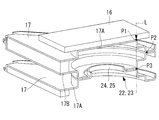
- FIG. 4A and 4B It is an expansion perspective view showing the lamination
- positioning figure which shows the relationship between the flat heat exchanger tube of the laminated heat exchanger which concerns on 3rd Embodiment of this invention, and the input position of the pressing force by a heat exchanger pressing member.
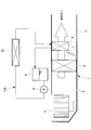
- FIG. 1 is a schematic configuration diagram of a vehicle air conditioner including a stacked heat exchanger and a heat medium heating device according to the first embodiment of the present invention.
- the vehicle air conditioner 1 is provided with a casing 3 that forms an air flow path 2 for taking outside air or air in the vehicle interior and controlling the temperature, and then guiding it to the vehicle interior.
- the air or the cabin air is sequentially sucked from the upstream side to the downstream side of the air flow path 2, the pressure is increased, and the blower 4 is pumped to the downstream side.
- the flow rate ratio of the cooler 5 that cools the air, the radiator 6 that heats the air that has passed through the cooler 5, and the amount of air that passes through the radiator 6 and the amount of air that bypasses the radiator 6 An air mix damper 7 that adjusts the temperature of the temperature-controlled air by adjusting and air-mixing on the downstream side thereof is installed.
- the downstream side of the casing 3 is connected to a plurality of outlets that blow out the temperature-controlled air into the vehicle compartment via an outlet mode switching damper and a duct (not shown).
- the cooler 5 constitutes a refrigerant circuit together with a compressor, a condenser, an expansion valve, etc., not shown, and cools the air passing therethrough by evaporating the refrigerant adiabatically expanded by the expansion valve.
- the radiator 6 constitutes a heat medium circulation circuit 10A together with the tank 8, the pump 9, and the heat medium heating device 10, and a heat medium (for example, antifreeze liquid) heated to a high temperature by the heat medium heating device 10 The air passing therethrough is heated by being circulated through.
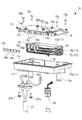
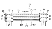
- FIG. 2 is an exploded perspective view for explaining a procedure for assembling the heat medium heating device 10 shown in FIG. 1, and FIG. 3A is a plan view of the heat medium heating device 10. .
- FIG. 3B shows a side view of the heat medium heating device 10.
- the heat medium heating device 10 includes a control board 13, an electrode plate 14 (see FIG. 3B), a plurality of semiconductor switching elements 12 (see FIG. 3B) made of IGBT, etc.
- a laminated heat exchanger 18 in which a pressing member (pressing member) 16, a plurality of sets (for example, three sets) of flat heat exchanger tubes 17 are stacked, and a plurality of sets of PTC elements (Positive Temperature Coefficient) 19 a (see FIG.
- a casing 11 that accommodates the control board 13, the electrode plate 14, the semiconductor switching element 12, the laminated heat exchanger 18, the PTC element 19a, the heat exchanger pressing member 16, and the like.
- a plurality of sets of PTC heaters 19 are configured by the electrode plate 14, the PTC element 19 a, an insulator described later, and the like.
- the casing 11 is divided into an upper half and a lower half, and includes an upper case 11a (see FIG. 3B) located in the upper half and a lower case 11b located in the lower half. ing. Inside the upper case 11a and the lower case 11b, by placing the upper case 11a on the opening 11c of the lower case 11b from above the lower case 11b, the control board 13, the semiconductor switching element 12, the heat exchanger pressing member 16, A space for accommodating the laminated heat exchanger 18, the electrode plate 14, a plurality of sets of PTC heaters 19 and the like is formed.
- a heat medium inlet path (heat medium outlet / inlet path) 11d for guiding the heat medium introduced into the stacked heat exchanger 18 and the heat medium flowing through the stacked heat exchanger 18 are led out.
- a heat medium outlet path (heat medium outlet / inlet path) 11e is integrally provided.
- the lower case 11b is formed of a resin material (for example, PBT) having a linear expansion close to that of the aluminum alloy material forming the flat heat exchanger tube 17 accommodated in the internal space.
- the upper case 11a is also preferably a molded product made of the same resin material as the lower case 11b.
- the lower surface of the lower case 11b is provided with a power harness hole 11f and a LV harness hole 11g (see FIG. 3A) for penetrating the distal ends of the power harness 27 and the LV harness 28.
- the power supply harness 27 supplies electric power to the PTC heater 19 via the control board 13 and the semiconductor switching element 12, and the two power supply harnesses provided on the control board 13 are branched at the tip end into a bifurcated shape.
- the terminal block 13c can be screwed with an electrode harness connecting screw 13b.
- the LV harness 28 transmits a control signal to the control board 13, and a tip portion of the LV harness 28 can be connected to the control board 13 with a connector.
- the semiconductor switching element 12 and the control board 13 constitute a control system that performs energization control on a plurality of sets of PTC heaters 19 based on a command from a host control device (ECU), and a plurality of semiconductor switching devices such as IGBTs.
- the energization state for a plurality of sets of PTC heaters 19 can be switched via the element 12.
- a plurality of sets of flat heat exchanger tubes 17 constituting the stacked heat exchanger 18 are stacked so as to sandwich the plurality of sets of PTC heaters 19 from both sides thereof.
- the flat heat exchanger tube 17 constituting the laminated heat exchanger 18 is configured by brazing and joining two molding plates 17A and 17B made of aluminum alloy.
- the flat tube portion 20 includes an inlet header portion 22 for supplying a heat medium formed at both ends thereof, and an outlet header portion 23 from which the heat medium is led out.
- the laminated heat exchanger 18 has a configuration in which, for example, three sets of flat heat exchanger tubes 17 are laminated so as to be parallel to each other. Three sets of flat heat exchanger tubes 17 are laminated in the order of lower, middle, and upper flat heat exchanger tubes 17c, 17b, and 17a.
- corrugated inner fins 21 are formed in the flat tube portions 20 of the flat heat exchanger tubes 17a, 17b, and 17c, whereby the flat heat exchanger tubes 17a, 17b, and 17c A plurality of heat medium flow passages communicating with each other in the axial direction are formed.
- the rigidity is increased by forming the inner fins 21 in the flat heat exchanger tubes 17a, 17b, and 17c. For this reason, even when the three sets of flat heat exchanger tubes 17a, 17b, and 17c are pressed against the inner bottom surface of the lower case 11b by the heat exchanger pressing member 16 of the substrate subassembly 15 described later, each flat heat exchanger tube 17a, 17b, and 17c are hardly deformed.
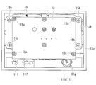
- the flat heat exchanger tubes 17a, 17b, and 17c have a long flat shape in the axial direction (left-right direction in FIG. 4A) when viewed in plan.
- the flat heat exchanger tubes 17a, 17b, and 17c are wide in the flat direction, that is, the direction orthogonal to the axial direction (vertical direction in FIG. 4B).
- An inlet header portion 22 and an outlet header portion 23 are formed at both ends in the axial direction of each flat heat exchanger tube 17a, 17b, 17c, that is, at both ends of the flat tube portion 20, and this inlet header portion 22 is formed.
- communication holes 24 and 25 are provided in the center of the outlet header portion 23, respectively.
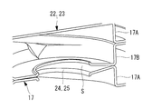
- the three sets of flat heat exchanger tubes 17c, 17b, and 17a of the lower, middle, and upper stages described above are interposed between the inlet header portion 22 and the outlet header portion 23 when stacked, for example, liquid applied to a sealing surface.
- the periphery of the communication holes 24 and 25 is sealed by a sealing material 26 such as a gasket or an O-ring.
- a plurality of sets of PTC heaters 19 are sandwiched between the flat tube portions 20 of the three sets of flat heat exchanger tubes 17c, 17b, 17a from both sides via the electrode plates 14 provided on both surfaces thereof. Are stacked in parallel.
- Spacers 29 may be inserted into the inlet header portion 22 and the outlet header portion 23 of the flat heat exchanger tubes 17c, 17b, 17a.
- each flat heat exchanger tube 17a, 17b, 17c are stacked as described above, and are pressed toward the inner bottom surface of the lower case 11b by the heat exchanger pressing member 16 of the substrate subassembly 15 described later.
- the pressing force by the heat exchanger pressing member 16 is concentrated on a specific portion on the same line L in the pressing force direction, and does not hit the portion strongly. ing.
- the input position of the pressing force by the heat exchanger pressing member 16 is P1, and the position where the pressing force is transmitted to the joining portion of the two molding plates 17A and 17B.
- P3 is a position where the pressing force is transmitted to the seal portion between the inlet header portion 22 and the outlet header portion 23, these three points P1, P2, and P3 are located on the same line L in the pressing force direction.
- at least one of P1, P2, and P3 is set at a position deviating from the same line L in the pressing force direction.
- the molding dies of the two molding plates 17A and 17B constituting the flat heat exchanger tube 17 are used.
- a mold structure in which at least one of the positions P1, P2, P3 is displaced, and a flat heat exchanger tube using molding plates 17A, 17B molded with the mold 17 may be configured.
- the three sets of flat heat exchanger tubes 17c, 17b, and 17a having the above-described configuration are stacked in this order, and are pressed toward the inner bottom surface of the lower case 11b via a substrate subassembly 15 described later, whereby a sealing material (liquid) Gasket, O-ring, etc.) 26, the lower surface of the inlet header portion 22 and the outlet header portion 23 of the middle flat heat exchanger tube 17b, and the inlet header portion 22 and the outlet of the lower flat heat exchanger tube 17c positioned therebelow Between the upper surface of the header portion 23 and the upper surface of the inlet header portion 22 and the outlet header portion 23 of the middle flat heat exchanger tube 17b, and the inlet header portion 22 and the outlet of the upper flat heat exchanger tube 17a located above the upper header heat exchanger tube 17b. The lower surface of the header portion 23 is in close contact with each other.
- the upper flat heat exchanger tube 17a, the middle flat heat exchanger tube 17b, and the lower flat heat exchanger tube 17a By laminating the flat heat exchanger tubes 17a, 17b, and 17c constituting the laminated heat exchanger 18 as described above, the upper flat heat exchanger tube 17a, the middle flat heat exchanger tube 17b, and the lower flat heat exchanger tube 17a.
- the communication holes 24 and 25 of the exchange tube 17 communicate with each other, the inlet header portions 22 and the outlet header portions 23 communicate with each other, and the periphery of the communication holes 24 and 25 is sealed by the sealing material 26. It is sealed in a sealed state.
- the heat medium guided from the heat medium inlet passage 11d is guided from the inlet header portions 22 of the stacked heat exchanger 18 into the flat tube portions 20 of the flat heat exchanger tubes 17a, 17b, and 17c.
- This heat medium is heated and heated by the PTC heater 19 in the process of flowing through the flat tube portion 20, flows out to each outlet header portion 23, and passes through the heat medium outlet passage 11e to the outside of the heat medium heating device 10.
- the heat medium led out from the heat medium heating device 10 is supplied to the radiator 6 via the heat medium circulation circuit 10A (see FIG. 1).
- the electrode plate 14 supplies power to the PTC element 19a, and is a plate material made of an aluminum alloy having a rectangular shape in plan view.
- One electrode plate 14 is laminated on both sides of the PTC element 19a so as to be in contact with the upper surface of the PTC element 19a and one electrode plate is in contact with the lower surface of the PTC element 19a.
- the two electrode plates 14 sandwich the upper surface of the PTC element 19a and the lower surface of the PTC element 19a.
- the electrode plate 14 positioned on the upper surface side of the PTC element 19a is disposed so that the upper surface thereof is in contact with the lower surface of the flat heat exchanger tube 17, and the electrode plate 14 positioned on the lower surface side of the PTC element 19a has a flat surface on the lower surface. It arrange
- the electrode plate 14 is between the lower flat heat exchanger tube 17c and the middle flat heat exchanger tube 17b, and between the middle flat heat exchanger tube 17b and the upper flat heat exchanger tube 17a. In total, two sheets are arranged in each.
- the four electrode plates 14 have substantially the same shape as the flat heat exchanger tubes 17a, 17b, and 17c.
- Each electrode plate 14 is provided with one terminal 14a on its long side.
- the terminals 14 a provided on the electrode plate 14 are positioned along the long side of the electrode plate 14 without overlapping when the electrode plates 14 are stacked. That is, the terminals 14a provided on each electrode plate 14 are provided with their positions slightly shifted along their long sides, and are provided so as to be arranged in series when the electrode plates 14 are stacked. ing.
- Each terminal 14a is provided so as to protrude upward, and is connected to a terminal block 13a provided on the control board 13 via a terminal connection screw 14b.
- control substrate 13 and the heat exchanger pressing member 16 are arranged in parallel, and a plurality of semiconductor switching elements 12 such as IGBTs installed on the upper surface of the heat exchanger pressing member 16 are sandwiched therebetween. Is.
- the control board 13 and the heat exchanger pressing member 16 are fixed by, for example, four board subassembly connection screws 15a, and thereby the board subassembly 15 is integrated.
- each terminal block 13 a is arranged in series on the lower surface of one side of the control board 13 constituting the substrate subassembly 15. ing.
- Two power supply harness terminal blocks 13c connected to the two branched ends of the power supply harness 27 are provided so as to be arranged in series with the four terminal blocks 13a.
- the terminal block 13 a and the power harness terminal block 13 c are provided so as to protrude downward from the lower surface of the control board 13.
- Each terminal block 13 a and the power harness terminal block 13 c are arranged in series along the long side of the flat heat exchanger tube 17 of the laminated heat exchanger 18.
- Each terminal block 13a and power harness terminal block 13c provided on the control board 13 are provided so as to be positioned slightly above the opening 11c of the lower case 11b. For this reason, the terminal 14a of the electrode plate 14 connected to each terminal block 13a and the terminal block 13c for power harnesses, and the front-end
- the semiconductor switching 12 made of an IGBT or the like is a transistor formed by resin molding in a substantially rectangular shape.
- the semiconductor switching 12 is a heat generating element that generates heat when activated, and is located on the upper surface of the heat exchanger pressing member 16 and in the vicinity of the inlet header portion 22 of the upper flat heat exchanger tube 17a of the laminated heat exchanger 18. It is screwed through a connection screw 12a and cooled by using the heat exchanger pressing member 16 as a heat sink.
- the heat exchange pressing member 16 constituting the substrate subassembly 15 is a flat quadrilateral (rectangular) aluminum alloy plate when viewed in plan.
- This heat exchanger pressing member 16 is larger than the control board 13 in the axial direction (left and right direction in FIG. 3A), and covers the upper surfaces of the flat heat exchanger tubes 17a, 17b, and 17c of the laminated heat exchanger 18.
- the size can be. Holes through which the board subassembly fixing screws 15b (see FIG. 3A) for fixing the heat exchanger pressing member 16 to the lower case 11b can be passed through the four corners of the heat exchanger pressing member 16 which is made larger in the axial direction than the control board 13. (Not shown) are provided at four locations.
- the substrate subassembly 15 is placed above the upper flat heat exchanger tube 17a of the laminated heat exchanger 18. That is, the substrate subassembly 15 is disposed such that the lower surface of the heat exchanger pressing member 16 is in contact with the upper surface of the upper flat heat exchanger tube 17a.
- the board subassembly 15 is configured such that the heat exchanger pressing member 16 is screwed to the lower case 11b via four board subassembly fixing screws 15b, so that the lower surface of the heat exchanger pressing member 16 and the inner bottom surface of the lower case 11b are fixed. In between, three sets of flat heat exchanger tubes 17a, 17b, and 17c stacked, and two sets of PTC heaters 19 sandwiched therebetween are sandwiched.
- the heat exchanger pressing member 16 constituting the substrate subassembly 15 is a plate material made of aluminum alloy, the heat exchanger pressing member 16 is subjected to cold heat of the heat medium flowing in the flat heat exchanger tubes 17a, 17b, and 17c of the laminated heat exchanger 18.
- the heat exchanger pressing member 16 is used as a heat sink for cooling the semiconductor switching element 12 such as an IGBT.
- lower flat heat exchanger tubes 17c in the three sets of flat heat exchanger tubes 17 constituting the laminated heat exchanger 18 are arranged in the inner space of the lower case 11b so as to be substantially parallel to the inner bottom surface of the lower case 11b.
- both surfaces of the PTC heater 19 are sandwiched by insulating sheets (not shown) on the flat tube portion 20 of the flat heat exchanger tube 17c, and stacked from above the lower flat heat exchanger tube 17c.
- a sealing material 26 such as a liquid gasket and an O-ring is interposed on the sealing surfaces of the upper surface of the inlet header portion 22 and the outlet header portion 23 of the lower flat heat exchanger tube 17c, and the middle flat heat exchanger tube 17b is disposed thereon from above. Laminate.
- both surfaces of the PTC heater 19 are sandwiched by insulating sheets in the same manner as described above, and stacked from above the middle flat heat exchanger tube 17b.
- a sealing material 26 similar to the above is applied to the sealing surfaces on the upper surfaces of the inlet header portion 22 and the outlet header portion 23 of the middle flat heat exchanger tube 17b, and the upper flat heat exchanger from above the middle flat heat exchanger tube 17b.
- the tubes 17a are stacked.
- the substrate subassembly 15 After the substrate subassembly 15 is laminated from above the laminated upper flat heat exchanger tube 17a so that the heat exchanger pressing member 16 is located below, the substrate subassembly 15 laminated on the upper flat heat exchanger tube 17a.
- the heat exchanger pressing member 16 is fastened and fixed to the lower case 11b by the board subassembly fixing screw 15b.
- the board subassembly fixing screw 15b As a result, between the inlet header portions 22 and between the outlet header portions 23 of the flat heat exchanger tubes 17a, 17b, and 17c are pressed and brought into close contact with the inner bottom surface of the lower case 11b, and between the inlet header portions 22 and the outlet header portions.
- the periphery of the communication holes 24 and 25 between 23 is sealed by the sealing material 26.
- the liquid gasket applied to the inlet header portion 22 and the outlet header portion 23 is pressed and brought into close contact with the three sets of flat heat exchanger tubes 17a, 17b, and 17c. A part of the surface protrudes from the mating surfaces and is cured by reacting with moisture in the air by contacting with the air. Because of this pressing, the inlet header portions 22 and the outlet header portions 23 of the flat heat exchanger tubes 17 are brought into close contact with each other.
- the lower flat heat exchanger tubes 17c and the intermediate flat heat exchanger tubes 17b, and the intermediate flat heat exchanger tubes 17b The PTC heater 19 and the electrode plate 14 sandwiched between the upper flat heat exchanger tubes 17a are also in close contact with the outer surfaces of the flat tube portions 20 of the flat heat exchanger tubes 17a, 17b, and 17c, respectively, and the contact thermal resistance therebetween is reduced. Will be.
- each terminal block 13a provided on the control board 13 constituting the board subassembly 15 and the terminal 14a of each electrode plate 14 are permanently fixed by the terminal connecting screw 14b, and the power harness harness hole 11f is fixed.
- the power harness 27 is inserted, and the front end portion thereof and each power harness terminal block 13c provided on the control board 13 are screwed together with a power harness connecting screw 13b.
- the distal end portion of the LV harness 28 is inserted into the lower case 11 b through the LV harness hole 11 g opened in the side wall of the lower case 11 b and connected to the control board 13 by a connector.
- the power harness 27 is fixed from the outer bottom surface of the lower case 11b with the power harness fixing screw 27a, and the LV harness 28 is fixed to the LV harness hole 11g.
- a sealing material (which may be a liquid gasket or an O-ring similar to those interposed on the upper surfaces of the inlet header portion 22 and the outlet header portion 23) is interposed in the opening portion 11c of the lower case 11b, and further the opening of the lower case 11b.
- the upper case 11a is placed on the portion 11c from above, and a clip portion (not shown) provided on the upper case 11a is hooked on a claw portion (not shown) provided on the lower case 11b, so that the upper case By assembling 11a and the lower case 11b, the assembly of the heat medium heating device 10 is completed (terminated).
- the liquid gasket (sealing material) 26 used in the present embodiment is excellent in heat resistance and is used for sealing between the inlet header portions 22 and between the outlet header portions 23 of the flat heat exchanger tube 17 exposed to high temperature. It is a suitable curable liquid sealing material that is cured by contact with moisture in the air.
- a silicone-based liquid gasket having a product number 1207d mainly containing silicone manufactured by ThreeBond Co., Ltd. can be used.
- the heat medium heating device 10 and the vehicle air conditioner 1 using the same using the same, the following operational effects can be obtained.
- a plurality of sets (three sets) of flat heat exchanger tubes 17 sequentially stacked on at least both surfaces of the PTC heater 19 are stacked in parallel to each other, and heat exchange with the control board 13 is performed on the upper surface of the upper flat heat exchanger tube 17a.
- a substrate subassembly 15 combined with a pressing member (pressing member) 16 is provided, and this is fastened and fixed to the lower case 11b, whereby the three sets of flat heat exchanger tubes 17 and two sets of PTC heaters 19 are pressure-bonded.
- the laminated heat exchanger 18 is assembled.
- the sealing material (liquid gasket, O-ring, etc.) 26 interposed between the inlet header portions 22 and the outlet header portions 23 of the laminated heat exchanger 18 is brought into close contact, and a plurality of sets of flat heat exchanger tubes 17,
- the closeness between the PTC heaters 19 stacked between them can be increased. Therefore, the contact heat resistance between each flat heat exchanger tube 17 and the PTC heater 19 can be reduced, the heat transfer efficiency from the PTC heater 19 to the flat heat exchanger tube 17 can be improved, and the laminated heat exchanger 18 and the heat medium can be improved.
- the heating device 10 can be improved in performance.
- the PTC heater 19 and the heat medium can be heat-exchanged via a laminated heat exchanger 18 configured by laminating a plurality of sets of flat heat exchanger tubes 17, the heat medium distribution which is a large die-cast part A box or the like can be dispensed with, and therefore, the heat medium heating device 10 can be reduced in size and weight and cost.
- the pressing force by the heat exchanger pressing member 16 is dispersed at the joint portion of the two molding plates 17A and 17B or the seal portion between the inlet header portion 22 and the outlet header portion 23, and the pressing force is A specific portion of the seal portion between the outlet header portions 23 is not strongly hit.
- FIG. 6A and FIG. 6B show an analysis result in the case where P1, P2 and P3 are positioned on the same line L in the pressing force direction, and one of them P2 is shifted from the same line L in the pressing force direction.
- FIG. 6A shows the analysis result when the position is set.
- the space between the inlet header portion 22 and the outlet header portion 23 is sealed through a sealing material 26 such as a liquid gasket or an O-ring interposed on the sealing surface.
- a sealing material 26 such as a liquid gasket or an O-ring interposed on the sealing surface.
- a semiconductor switching 12 such as an IGBT which is a heating element is provided.
- the laminated heat exchanger tube 17 and the PTC heater 19 are pressed by the heat exchanger holding member 16 and the control board 13, and the semiconductor switching 12 is removed from the flat heat exchanger tube 17 using the heat exchanger holding member 16 as a heat sink. It can be cooled by cold heat. Therefore, the cooling performance of the semiconductor switching 12 can be ensured, and the heat medium heating device 10 can be improved in performance. Since the pressing of the laminated flat heat exchanger tube 17 and the cooling of the semiconductor switching 12 are combined by the heat exchanger pressing member 16, the number of parts constituting the heat medium heating device 10 can be reduced, and therefore the heat medium The whole heating apparatus 10 can be reduced in size.
- a heat medium inlet path (heat medium outlet / inlet path) 11d for introducing the heat medium and a heat medium outlet path (heat medium outlet / inlet path) 11e for discharging the heat medium are integrally formed in the lower case 11b. .
- the stress concerning the laminated flat heat exchanger tube 17 can be disperse
- a control system composed of a control board 13 for controlling energization to the PTC heater 19 and the semiconductor switching 12 is integrated as a board subassembly 15 and incorporated in the casing 11, so that electrical connection with each electrode plate 14 is achieved.
- the wiring path is not complicated, the assembling property can be facilitated, the number of parts can be reduced, the wiring path of the control system is simplified, and the flat heat exchanger tube 17, PTC A high-performance and compact heat medium heating device 10 in which the heater 19 and its control system are integrally incorporated in the casing 11 can be obtained.
- the semiconductor switching (heating element) 12 such as an IGBT connected to the control board 13 is arranged at a position close to the inlet header 22 side of the flat heat exchanger tube 17. For this reason, the semiconductor switching 12 can be cooled by the heat medium having a relatively low temperature before being heated by the PTC heater 19, and the cooling performance of the semiconductor switching 12 can be further enhanced.
- the heat transfer efficiency is improved, and there is no leakage of the heat medium, and a high-performance heat medium heating device 10 that is lightweight and compact is incorporated to heat the heat medium circulated in the radiator 6. Therefore, it is possible to improve the reliability and the air conditioning performance of the vehicle air conditioner 1, reduce the installation space, and improve the mountability to the vehicle.
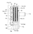
- the present embodiment differs from the first embodiment described above in that a burring is provided around the communication holes 24 and 25 of the inlet header portion 22 and the outlet header portion 23 of the flat heat exchanger tube 17. Since other points are the same as those in the first embodiment, description thereof will be omitted.
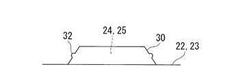
- the burrings 30 and 31 are formed on the peripheral edges of the communication holes 24 and 25 provided in the inlet header portion 22 and the outlet header portion 23 of the flat heat exchanger tube 17 so as to be fitted with each other during lamination. It is said.
- the burrings 30 and 31 are tapered burrings.
- the upper and lower inlet header portions 22 and the outlet headers are stacked.
- the burrings 30 and 31 are fitted with each other, and the tapered surfaces thereof are in close contact with each other.
- a sealing material 26 such as a liquid gasket or an O-ring is also interposed on the tapered surfaces of the burrings 30 and 31 during lamination.
- the communication holes 24 of the inlet header portion 22 and the outlet header portion 23 are provided with the burrings 30 and 31 that are inlay-fitted with each other at the periphery of the communication holes 24 and 25 of the inlet header portion 22 and the outlet header portion 23. , 25 can be improved by the burrings 30 and 31, and deformation at the time of pressing by the heat exchanger pressing member 16 can be further reduced. Since the burrings 30 and 31 can be used for positioning at the time of laminating a plurality of flat heat exchanger tubes 17, it is possible to prevent a sealing failure due to misalignment. Therefore, the sealing performance between the inlet header portion 22 and the outlet header portion 23 of the multiple sets of flat heat exchanger tubes 17 can be improved, and leakage of the heat medium can be reliably prevented.
- burrings 30 and 31 are tapered, a plurality of sets of flat heat exchanger tubes 17 are stacked, and the inlet header portion 22 and the outlet header portion 23 are pressed by the heat exchanger pressing member 16 and brought into close contact with each other. Is absorbed by the tapered portion, the inlet header portion 22 and the outlet header portion 23 can be reliably brought into close contact with each other, and the crossing of the flat heat exchanger tube 17 including the inlet / outlet header portions 22 and 23 is also absorbed by the tapered portion. Can do. Therefore, the sealing performance between the inlet header portion 22 and the outlet header portion 23 of the multiple sets of flat heat exchanger tubes 17 can be further improved, and leakage of the heat medium can be reliably prevented.
- a bellows-like microprojection 32 may be provided on the tapered surface of the burring 30, and by providing such a microprotrusion 32, the upper and lower burrings 30, 31 are fitted with an inlay. When combined, the burrings 30 and 31 come into contact with each other with the minute protrusions 32, so that the sealing performance can be further improved.
- FIG. 1 a third embodiment of the present invention will be described with reference to FIG.
- This embodiment is different from the first embodiment described above in that the position on the plane of the input position P1 of the pressing force by the heat exchanger pressing member 16 is specified. Since other points are the same as those in the first embodiment, description thereof will be omitted.
- the heat exchanger pressing member 16 having a quadrilateral shape is screwed and fixed to the lower case 11b at the four corners (four corners) via the four substrate subassembly fixing screws 15b.
- the input position P1 of the pressing force is the position of the four fixing screws 15b as shown in FIG.
- the heat exchanger pressing member 16 is fastened and fixed and a pressing force is applied to the flat heat exchanger tube 17, the circumferential direction of the communication holes 24 and 25 of the inlet header portion 22 and the outlet header portion 23 is set. The force is distributed to the sealing holes 24 and 25, so that a portion that locally hits the sealing portions around the communication holes 24 and 25 can be eliminated.
- the present invention is not limited to the invention according to the above-described embodiment, and can be modified as appropriate without departing from the scope of the invention.
- the flat heat exchanger tubes 17 are stacked in three layers, and the PTC heater 19 is incorporated between them.
- the present invention is not limited to this, and the flat heat exchanger tubes 17 and the PTC heaters 19 Of course, the number of layers may be increased or decreased.
- the flat heat exchanger tube 17 demonstrated the example in which the flat tube part 20, the inlet header part 22 and the outlet header part 23 of both ends were integrated, the flat tube part 20 and the inlet header of both ends were demonstrated. It is good also as a flat heat exchanger tube which shape
- the burrings 30 and 31 provided in the inlet header portion 22 and the outlet header portion 23 are not limited to a tapered shape, and may be modified into various shapes such as being provided in a vertical shape.
Landscapes
- Engineering & Computer Science (AREA)
- Physics & Mathematics (AREA)
- Thermal Sciences (AREA)
- Mechanical Engineering (AREA)
- General Engineering & Computer Science (AREA)
- Chemical & Material Sciences (AREA)
- Combustion & Propulsion (AREA)
- Air-Conditioning For Vehicles (AREA)
- Heat-Exchange Devices With Radiators And Conduit Assemblies (AREA)
Abstract
扁平熱交チューブ間にPTCヒータを挟み押圧して密接させる際の出入口ヘッダ部のシール部分の変形によるシール性の低下を防止できる積層型熱交換器、それを用いた熱媒体加熱装置および車両用空調装置を提供する。扁平チューブ部の両端に出入口ヘッダ部(22,23)が設けられている2枚の成形プレート(17A,17B)を接合して構成される扁平熱交チューブ(17)と、出入口ヘッダ部(22,23)が連通穴(24,25)を介して互いに連通されるように積層された扁平熱交チューブ(17)を押圧して密着させる熱交押え部材(16)と、を備えた積層型熱交換器(18)にあって、出入口ヘッダ部(22,23)に対して、熱交押え部材(16)による押圧力の入力位置(P1)と、該押圧力が2枚の成形プレートの接合部分に伝わる位置(P2)と、押圧力が出入口ヘッダ部間のシール部分に伝わる位置(P3)との少なくとも1つが、押圧力方向の同一線(L)上から外れた位置に設定されている。
Description
本発明は、熱媒体を加熱するための積層型熱交換器、それを用いた熱媒体加熱装置および車両用空調装置に関するものである。
電気自動車やハイブリッド車等に適用される車両用空調装置にあって、暖房用の熱源となる被加熱媒体を加熱する熱媒体加熱装置の1つに、正特性サーミスタ素子(Positive Temperature Coefficient;以下、PTC素子という。)を発熱要素とするPTCヒータを用いたものが知られている。かかる熱媒体加熱装置において、特許文献1には、熱媒体の出入口を備えたハウジング内を隔壁により多数の加熱室と熱媒体循環室とに区画し、加熱室側に隔壁と接触するように挿入設置されたPTC素子により、循環室内を流れる熱媒体を加熱するように構成した熱媒体加熱装置が開示されている。
特許文献2には、PTC素子を挟んでその両面に電極板、絶縁層および伝熱層を設けて平板状のPTCヒータを構成し、該PTCヒータの両面に熱媒体の出入口を備えた互いに連通されている一対の熱媒体流通ボックスを積層し、更にその外面に基板収容ボックスを配設した構成の熱媒体加熱装置が示されている。特許文献3,4には、チューブエレメントの両端に設けられるヘッダ部(タンク部)の連通穴周りにバーリングを形成し、それを嵌合することによって積層時の位置合わせを容易化するとともに、接合時の位置ずれによる接合不良を防止するように構成した積層型熱交換器が開示されている。
特許文献5には、冷却媒体が流通される扁平冷却管を電子部品の両面を挟持するように複数組積層した積層型冷却器であって、冷却管の開口部に伸縮可能な連通部材を接続して隣接する冷却管の開口部間を連通するとともに、該開口部の特定周囲部にリブを設け、冷却管の厚さ方向の圧縮強度を積層型冷却器の製造時にかかる荷重に対して充分に大きくしているものが開示されている。
しかしながら、特許文献1に示すものは、隔壁により形成された加熱室内にPTC素子を挿入設置した構成としているため、伝熱面となる隔壁間にPTC素子を密接させて挿入することは容易でなく、隔壁とPTC素子間の接触熱抵抗が大きくなり、伝熱効率が低下する等の課題があった。特許文献2に示すものは、PTCヒータの両面に放熱フィンを有する一対の熱媒体流通ボックスを積層するとともに、その外側に基板収容ボックスおよび蓋体を設けて熱媒体流路を密閉し、それをボルトで一体に締結した積層構造としているため、PTCヒータと熱媒体流通ボックス間の接触熱抵抗を小さくできるが、熱媒体流通ボックスや基板収容ボックスを耐熱性や伝熱性を考慮して、アルミダイカスト製としており、小型軽量化には限界があるとともに、高価になる等の課題があった。
上記の課題を解消すべく、熱媒体加熱装置に積層型熱交換器を適用することが考えられている。しかし、積層型熱交換器の場合、特許文献3,4に示されるように、ロウ材がクラッドされた材料で成形されたチューブエレメントとフィンとを積層して炉中ロウ付けするのが一般的である。従って、治具を用いて仮組み立てした熱交換器を炉中に投入してロウ付けすればよく、積層時の位置合わせを容易化し、接合時の位置ずれを防止することにより良好なシール性が得られるが、PTCヒータを挟み込んでチューブエレメントと密接させる必要がある上記熱媒体加熱装置では、このような手法を採ることはできない。
そこで、特許文献5に示されるように、電子部品の両面と冷却管とを確実に密接させるため、冷却管の開口部間を伸縮可能な連通部材で接続する構成とし、この連通部材を加圧状態でロウ付けできるように、冷却管の開口部周りにリブを設け、冷却管の厚さ方向の圧縮強度を高めて加圧時の変形を防止するようにしたものが提案されている。しかし、伸縮可能な連通部材が必要な上に、連通部材を加圧状態でロウ付けするため、冷却管の開口部周りにリブを設けて変形を防止する等、部品点数の増加や構成の複雑化は避け難く、コストアップ要因となる等の課題があった。
本発明は、このような事情に鑑みてなされたものであって、複数組の扁平熱交チューブを積層し、その間にPTCヒータを挟み押圧して密接させる際の入口ヘッダ部および出口ヘッダ部のシール部分の変形によるシール性の低下を防止できる積層型熱交換器、それを用いた熱媒体加熱装置および車両用空調装置を提供することを目的とする。
上記した課題を解決するために、本発明の積層型熱交換器、それを用いた熱媒体加熱装置および車両用空調装置は、以下の手段を採用する。
すなわち、本発明の一態様にかかる積層型熱交換器は、熱媒体が流通される扁平チューブ部の両端に入口ヘッダ部および出口ヘッダ部が設けられている2枚の成形プレートを接合して構成される扁平熱交チューブと、前記入口ヘッダ部および前記出口ヘッダ部が連通穴を介して互いに連通されるように積層された複数組の前記扁平熱交チューブを押圧して密着させる熱交押え部材と、を備えた積層型熱交換器にあって、前記入口ヘッダ部および前記出口ヘッダ部に対して、前記熱交押え部材による押圧力の入力位置と、該押圧力が前記2枚の成形プレートの接合部分に伝わる位置と、前記押圧力が前記入口ヘッダ部および前記出口ヘッダ部間のシール部分に伝わる位置との少なくとも1つが、前記押圧力方向の同一線上から外れた位置に設定されている。
すなわち、本発明の一態様にかかる積層型熱交換器は、熱媒体が流通される扁平チューブ部の両端に入口ヘッダ部および出口ヘッダ部が設けられている2枚の成形プレートを接合して構成される扁平熱交チューブと、前記入口ヘッダ部および前記出口ヘッダ部が連通穴を介して互いに連通されるように積層された複数組の前記扁平熱交チューブを押圧して密着させる熱交押え部材と、を備えた積層型熱交換器にあって、前記入口ヘッダ部および前記出口ヘッダ部に対して、前記熱交押え部材による押圧力の入力位置と、該押圧力が前記2枚の成形プレートの接合部分に伝わる位置と、前記押圧力が前記入口ヘッダ部および前記出口ヘッダ部間のシール部分に伝わる位置との少なくとも1つが、前記押圧力方向の同一線上から外れた位置に設定されている。
上記態様によれば、複数組の扁平熱交チューブが熱交押え部材により押圧され、互いに密着されている積層型熱交換器にあって、入口ヘッダ部および出口ヘッダ部に対して、熱交押え部材による押圧力の入力位置と、押圧力が2枚の成形プレートの接合部分に伝わる位置と、押圧力が入口ヘッダ部および出口ヘッダ部間のシール部分に伝わる位置との少なくとも1つが、押圧力方向の同一線上から外れた位置に設定されているため、熱交押え部材による押圧力が、2枚の成形プレートの接合部分または入口ヘッダ部および出口ヘッダ部間のシール部分で分散され、該押圧力が入口ヘッダ部および出口ヘッダ部間のシール部分の特定部位に強く当たることがなくなり、該押圧力が特定の部位に強く当たることによる周りの変形を抑制し、シール面での隙間の発生を阻止することができる。従って、扁平熱交チューブ内に内圧が負荷された際のシール性を向上し、熱媒体の漏れを防止することができる。
上記の積層型熱交換器において、前記入口ヘッダ部および前記出口ヘッダ部の前記連通穴周りに、互いにインロー嵌合されるバーリングが設けられていることとしてもよい。
このようにすることで、入口ヘッダ部および出口ヘッダ部の連通穴周りに、互いにインロー嵌合されるバーリングが設けられているため、入口ヘッダ部および出口ヘッダ部の連通穴周りの強度をバーリングにより向上し、熱交押え部材による押圧時の変形をより小さくすることができるとともに、該バーリングを扁平熱交チューブの積層時の位置決めに利用できることから、位置ずれによるシール不良をも防止することができる。従って、複数組の扁平熱交チューブの入口ヘッダ部および出口ヘッダ部間のシール性を向上し、熱媒体の漏えいを確実に防止することができる。
上記の積層型熱交換器において、前記バーリングは、テーパー状とされていることとしてもよい。
このようにすることで、バーリングが、テーパー状とされているため、複数組の扁平熱交チューブを積層して入口ヘッダ部および出口ヘッダ部を熱交押え部材により押圧して互いに密接させた際の微小変形をテーパー部分で吸収し、入口ヘッダ部および出口ヘッダ部同士を確実に密接させることができるとともに、出入口ヘッダ部を含む扁平熱交チューブの寸法交差もテーパー部分で吸収することができる。従って、複数組の扁平熱交チューブの入口ヘッダ部および出口ヘッダ部間のシール性を更に向上することができ、熱媒体の漏えいを確実に防止することができる。
上述のいずれかの積層型熱交換器において、前記入口ヘッダ部および前記出口ヘッダ部間は、それぞれシール面に介在されたシール材を介してシールされていることとしてもよい。
このようにすることで、入口ヘッダ部および出口ヘッダ部間が、それぞれシール面に介在されたシール材を介してシールされているため、複数組の扁平熱交チューブを積層する際、その入口ヘッダ部および出口ヘッダ部間のシール面にシール材(液状ガスケット、Oリング等)を介在させ、それらを熱交押え部材により押圧して入口ヘッダ部および出口ヘッダ部間を密接させることによって、入口ヘッダ部および出口ヘッダ部間をシールすることができる。従って、入口ヘッダ部および出口ヘッダ部間のシール性を十分に確保し、熱媒体の漏えい防止に対する信頼性を向上することができるとともに、シール構造の簡素化、組み立ての容易化を図ることができる。
上述のいずれかの積層型熱交換器において、前記熱交押え部材は、扁平熱交チューブの長さ方向に対応した四辺形状とされ、その両端各2箇所の締め付け固定部を押圧力の入力位置としたとき、前記扁平熱交チューブの前記入口ヘッダ部および前記出口ヘッダ部に設けられている前記連通穴の中心が、前記両端各2箇所の入力位置を結ぶ線上に位置されていることとしてもよい。
このようにすることで、熱交押え部材が、扁平熱交チューブの長さ方向に対応した四辺形状とされ、その両端各2箇所の締め付け固定部を押圧力の入力位置としたとき、扁平熱交チューブの入口ヘッダ部および出口ヘッダ部に設けられている連通穴の中心が、両端各2箇所の入力位置を結ぶ線上に位置されているため、熱交押え部材を締め付け固定して扁平熱交チューブに押圧力を加えたとき、入口ヘッダ部および出口ヘッダ部の連通穴周方向に力が分散され、連通穴周りのシール部分において局所的に強く当たる部分をなくすることができる。従って、連通穴周りのシール部分での変形を抑制し、シール面での隙間の発生を阻止して入口ヘッダ部および出口ヘッダ部間のシール性を向上することができる。
上述の積層型熱交換器における複数組の前記扁平熱交チューブの前記扁平チューブ部間に複数組のPTCヒータが組み込まれ、該PTCヒータにより前記扁平熱交チューブ内を流通される熱媒体が加熱可能とされていることとしてもよい。
このようにすることで、上述の積層型熱交換器における複数組の扁平熱交チューブの扁平チューブ部間に複数組のPTCヒータが組み込まれ、該PTCヒータにより扁平熱交チューブ内を流通される熱媒体が加熱可能とされているため、複数組の扁平熱交チューブ間に組み込まれる複数組のPTCヒータと、各扁平熱交チューブの扁平チューブ部とを熱交押え部材の押圧力により確実に密接させ、PTCヒータと扁平熱交チューブ間の接触熱抵抗を低減することができる。従って、PTCヒータと扁平熱交チューブ間の伝熱効率を高めて加熱性能を向上し、熱媒体加熱装置を高性能化することができるともに、熱媒体の漏えい等を確実に解消することができる。
本発明にかかる車両用空調装置は、空気流路中に配設されている放熱器に対して、熱媒体加熱装置で加熱された熱媒体が循環可能に構成されている車両用空調装置において、前記熱媒体加熱装置が、上記の熱媒体加熱装置とされている。
本発明によれば、空気流路中に配設されている放熱器に対して、上述の熱媒体加熱装置により加熱された熱媒体が循環可能に構成されているため、放熱器に対する熱媒体循環回路中での熱媒体の漏えい等を確実に解消することができるとともに、熱媒体加熱装置による熱媒体の加熱性能を高めることができる。従って、車両用空調装置の信頼性向上と空調性能の向上を図ることができる。
本発明の積層型熱交換器によると、熱交押え部材による押圧力が、2枚の成形プレートの接合部分または入口ヘッダ部および出口ヘッダ部間のシール部分で分散され、該押圧力が入口ヘッダ部および出口ヘッダ部間のシール部分の特定部位に強く当たることがなくなり、該押圧力が特定の部位に強く当たることによる周りの変形を抑制し、シール面での隙間の発生を阻止することができるため、扁平熱交チューブ内に内圧が負荷された際のシール性を向上し、熱媒体の漏れを防止することができる。
本発明の熱媒体加熱装置によると、複数組の扁平熱交チューブ間に組み込まれる複数組のPTCヒータと、各扁平熱交チューブの扁平チューブ部とを熱交押え部材の押圧力により確実に密接させ、PTCヒータと扁平熱交チューブ間の接触熱抵抗を低減することができるため、PTCヒータと扁平熱交チューブ間の伝熱効率を高めて加熱性能を向上し、熱媒体加熱装置を高性能化することができるともに、熱媒体の漏えい等を確実に解消することができる。
本発明の車両用空調装置によると、放熱器に対する熱媒体循環回路中での熱媒体の漏えい等を確実に解消することができるとともに、熱媒体加熱装置による熱媒体の加熱性能を高めることができるため、車両用空調装置の信頼性向上と空調性能の向上を図ることができる。
以下に、本発明にかかる実施形態について、図面を参照して説明する。
[第1実施形態]
以下、本発明の第1実施形態について、図1ないし図6Bを用いて説明する。
図1には、本発明の第1実施形態に係る積層型熱交換器および熱媒体加熱装置を備えた車両用空調装置の概略構成図が示されている。
車両用空調装置1は、外気または車室内空気を取り込んで温調した後、それを車室内へと導くための空気流路2を形成するケーシング3を備えている。
[第1実施形態]
以下、本発明の第1実施形態について、図1ないし図6Bを用いて説明する。
図1には、本発明の第1実施形態に係る積層型熱交換器および熱媒体加熱装置を備えた車両用空調装置の概略構成図が示されている。
車両用空調装置1は、外気または車室内空気を取り込んで温調した後、それを車室内へと導くための空気流路2を形成するケーシング3を備えている。
ケーシング3の内部には、空気流路2の上流側から下流側にかけて順次、外気または車室内空気を吸い込んで昇圧し、それを下流側へと圧送するブロア4と、該ブロア4により圧送される空気を冷却する冷却器5と、冷却器5を通過して冷却された空気を加熱する放熱器6と、放熱器6を通過する空気量と放熱器6をバイパスする空気量との流量割合を調整し、その下流側でエアミックスさせることによって、温調風の温度を調節するエアミックスダンパ7と、が設置されている。
ケーシング3の下流側は、図示しない吹き出しモード切替えダンパおよびダクトを介して温調された空気を車室内に吹き出す複数の吹き出し口に接続されている。
冷却器5は、図示省略された圧縮機、凝縮器、膨張弁等と共に冷媒回路を構成し、膨張弁で断熱膨張された冷媒を蒸発させることによって、そこを通過する空気を冷却するものである。放熱器6は、タンク8、ポンプ9、および熱媒体加熱装置10と共に熱媒体循環回路10Aを構成し、熱媒体加熱装置10により高温に加熱された熱媒体(例えば、不凍液等)がポンプ9を介して循環されることにより、そこを通過する空気を加温するものである。
冷却器5は、図示省略された圧縮機、凝縮器、膨張弁等と共に冷媒回路を構成し、膨張弁で断熱膨張された冷媒を蒸発させることによって、そこを通過する空気を冷却するものである。放熱器6は、タンク8、ポンプ9、および熱媒体加熱装置10と共に熱媒体循環回路10Aを構成し、熱媒体加熱装置10により高温に加熱された熱媒体(例えば、不凍液等)がポンプ9を介して循環されることにより、そこを通過する空気を加温するものである。
図2には、図1に示された熱媒体加熱装置10を組み立てる手順を説明するための分解斜視図が示され、図3Aには、その熱媒体加熱装置10の平面図が示されている。図3Bには、熱媒体加熱装置10の側面図が示されている。熱媒体加熱装置10は、図2に示されるように、制御基板13と、電極板14(図3B参照)と、IGBT等からなる複数個の半導体スイッチング素子12(図3B参照)と、熱交押え部材(押圧部材)16と、複数組(例えば、3組)の扁平熱交チューブ17を積層した積層型熱交換器18と、複数組のPTC素子(Positive Temperature Coefficient)19a(図3B参照)と、これらの制御基板13、電極板14、半導体スイッチング素子12、積層型熱交換器18、PTC素子19aおよび熱交押え部材16等を収容するケーシング11と、を備えている。電極板14、PTC素子19aおよび後述する絶縁体等により、複数組のPTCヒータ19が構成されている。
ケーシング11は、上半部と下半部とに2分割された構成となっており、上半部に位置するアッパケース11a(図3B参照)と、下半部に位置するロアケース11bとを備えている。アッパケース11aおよびロアケース11bの内部には、ロアケース11bの上方からロアケース11bの開口部11cにアッパケース11aを載置することによって、上記の制御基板13、半導体スイッチング素子12、熱交押え部材16、積層型熱交換器18、電極板14、および複数組のPTCヒータ19等を収容する空間が形成されるようになっている。
ロアケース11bの下面には、積層型熱交換器18に導入される熱媒体の導くための熱媒体入口路(熱媒体導出入路)11dおよび積層型熱交換器18内を流通した熱媒体を導出するための熱媒体出口路(熱媒体導出入路)11eが一体的に設けられている。ロアケース11bは、その内部空間に収容される扁平熱交チューブ17を形成しているアルミ合金材と線膨張が近い樹脂材料(例えば、PBT)により成形されている。アッパケース11aも、ロアケース11bと同じ樹脂材による成形品とすることが望ましい。このように、ケーシング11を樹脂材料で構成することにより、軽量化を図ることができる。
ロアケース11bの下面には、電源ハーネス27およびLVハーネス28の先端部を貫通するための電源ハーネス用孔11fおよびLVハーネス用孔11g(図3A参照)が開口されている。電源ハーネス27は、制御基板13および半導体スイッチング素子12を介してPTCヒータ19に電力を供給するものであり、先端部が2又状に分岐され、制御基板13に設けられている2つの電源ハーネス用端子台13cに電極ハーネス接続用ネジ13bによってネジ止め可能とされている。LVハーネス28は、制御基板13に制御用の信号を送信するものであり、その先端部は、制御基板13にコネクタ接続可能とされている。
半導体スイッチング素子12および制御基板13は、上位制御装置(ECU)からの指令に基づいて複数組のPTCヒータ19に対する通電制御を行う制御系を構成するものであり、IGBT等の複数個の半導体スイッチング素子12を介して複数組のPTCヒータ19に対する通電状態が切替えできるように構成されている。そして、この複数組のPTCヒータ19をその両面側から挟み込むように、積層型熱交換器18を構成する複数組の扁平熱交チューブ17が積層されている。
積層型熱交換器18を構成している扁平熱交チューブ17は、図4Aに示されるように、アルミ合金製の2枚の成形プレート17A,17Bをロウ付け接合して構成されたものであり、扁平チューブ部20と、その両端に形成されている熱媒体を供給する入口ヘッダ部22および熱媒体が導出される出口ヘッダ部23とを備えている。ここでの積層型熱交換器18は、例えば3組の扁平熱交チューブ17が互いに平行になるように積層された構成とされている。3組の扁平熱交チューブ17は、下段、中段、上段の扁平熱交チューブ17c、17b、17aの順に積層される。
扁平熱交チューブ17a、17b、17cの扁平チューブ部20内には、図4Bに示されるように、コルゲート状のインナーフィン21が形成され、これによって、各扁平熱交チューブ17a、17b、17c内には、その軸方向に連通している複数の熱媒体流通路が形成されている。各扁平熱交チューブ17a、17b、17c内にインナーフィン21が形成されることによって剛性が増大される。このため、後述する基板サブアッセンブリ15の熱交押え部材16により3組の扁平熱交チューブ17a、17b、17cが、ロアケース11bの内底面に対して押圧された場合においても、各扁平熱交チューブ17a、17b、17cが変形され難くされている。
扁平熱交チューブ17a、17b、17cは、平面視した場合、軸方向(図4Aにおいて左右方向)に長い扁平状を呈している。この扁平熱交チューブ17a、17b、17cは、扁平方向、すなわち、軸方向と直交する方向(図4Bにおいて上下方向)に幅広となっている。各扁平熱交チューブ17a、17b、17cの軸方向の両端部、すなわち、扁平チューブ部20の両端部には、入口ヘッダ部22と出口ヘッダ部23とが形成されており、この入口ヘッダ部22および出口ヘッダ部23の中心部には、それぞれ連通穴24,25が設けられている。
上記した下段、中段、上段の3組の扁平熱交チューブ17c、17b、17aは、積層される際に入口ヘッダ部22および出口ヘッダ部23に介在された、例えば、シール面に塗布された液状ガスケットまたはOリング等のシール材26により、連通穴24,25の周りがシールされるようになっている。そして、この3組の扁平熱交チューブ17c、17b、17aの扁平チューブ部20間に、複数組のPTCヒータ19が、その両面に設けられている電極板14を介して両側から挟み込まれることによって、平行に積層されている。扁平熱交チューブ17c、17b、17aの入口ヘッダ部22および出口ヘッダ部23内にスペーサ29を挿入してもよい。
各扁平熱交チューブ17a、17b、17cの入口ヘッダ部22および出口ヘッダ部23は、上記のように積層され、後述する基板サブアッセンブリ15の熱交押え部材16によりロアケース11bの内底面に向け押圧されて締め付け固定される際に、その押圧力が特定の部位に強く当たることにより該部位の周辺が変形し、隙間が生じることによるシール性の低下を防止するため、図5に示されるように、入口ヘッダ部22および出口ヘッダ部23に対して、熱交押え部材16による押圧力が押圧力方向の同一線L上の特定部位に集中され、該部位に強く当たることがないように構成されている。
つまり、入口ヘッダ部22および出口ヘッダ部23に対して、熱交押え部材16による押圧力の入力位置をP1、その押圧力が2枚の成形プレート17A,17Bの接合部分に伝達される位置をP2、該押圧力が入口ヘッダ部22および出口ヘッダ部23間のシール部分に伝達される位置をP3としたとき、このP1,P2,P3の3点が押圧力方向の同一線L上に位置されないように、P1,P2,P3の少なくとも1つが、押圧力方向の同一線L上から外れた位置に設定されるようにしている。
このように、P1,P2,P3位置の少なくとも1つを押圧力方向の同一線L上からずらすには、扁平熱交チューブ17を構成している2枚の成形プレート17A,17Bの成形金型を、予め解析した結果に基づき、P1,P2,P3位置の少なくとも1つの位置がずれるような形状とした型構造とし、該金型で成形された成形プレート17A,17Bを用いて扁平熱交チューブ17を構成すればよい。
上記構成とされた3組の扁平熱交チューブ17c、17b、17aは、この順に積層され、後述する基板サブアッセンブリ15を介してロアケース11bの内底面に向け押圧されることによって、シール材(液状ガスケット、Oリング等)26を介して中段扁平熱交チューブ17bの入口ヘッダ部22および出口ヘッダ部23の下面と、その下方に位置している下段扁平熱交チューブ17cの入口ヘッダ部22および出口ヘッダ部23の上面との間、および中段扁平熱交チューブ17bの入口ヘッダ部22および出口ヘッダ部23の上面と、その上方に位置している上段扁平熱交チューブ17aの入口ヘッダ部22および出口ヘッダ部23の下面との間がそれぞれ密接されるようになっている。
積層型熱交換器18を構成している扁平熱交チューブ17a、17b、17cを上記のように積層することによって、上段の扁平熱交チューブ17a、中段の扁平熱交チューブ17bおよび下段の扁平熱交チューブ17の各々の連通穴24,25が互いに連通され、入口ヘッダ部22同士および出口ヘッダ部23同士が互いに連通されるようになるとともに、各連通穴24,25の周囲がシール材26によって密封状態にシールされるようになっている。
これによって、熱媒体入口路11dから導かれた熱媒体は、積層型熱交換器18の各入口ヘッダ部22から各扁平熱交チューブ17a、17b、17cの扁平チューブ部20内へと導かれる。この熱媒体は、扁平チューブ部20内を流通する過程において、PTCヒータ19により加熱されて昇温され、各出口ヘッダ部23に流出し、熱媒体出口路11eを経て熱媒体加熱装置10の外部へと導出されるようになっている。熱媒体加熱装置10から導出された熱媒体は、熱媒体循環回路10A(図1参照)を介して放熱器6に供給されることになる。
電極板14は、図3Bに示されるように、PTC素子19aに電力を供給するものであり、平面視において、矩形状を呈するアルミ合金製の板材とされている。電極板14は、PTC素子19aを挟んでその両面に、PTC素子19aの上面に接するように一枚、PTC素子19aの下面に接するように一枚それぞれ積層されている。これら2枚の電極板14によって、PTC素子19aの上面と、PTC素子19aの下面とが挟み込まれるようになっている。
PTC素子19aの上面側に位置する電極板14は、その上面が扁平熱交チューブ17の下面に接するように配置され、PTC素子19aの下面側に位置する電極板14は、その下面が扁平熱交チューブ17の上面に接するように配置されている。本実施形態の場合には、電極板14は、下段の扁平熱交チューブ17cと中段の扁平熱交チューブ17bとの間、中段の扁平熱交チューブ17bと上段の扁平熱交チューブ17aとの間に各々2枚、合計4枚配置されている。
4枚の各電極板14は、扁平熱交チューブ17a、17b、17cと略同一形状とされている。各電極板14は、その長辺側に1つの端子14aが設けられている。電極板14に設けられている端子14aは、各電極板14を積層させた場合に重なることなく、電極板14の長辺に沿って位置している。すなわち、各電極板14に設けられている端子14aは、その長辺に沿って少しずつ位置がずらされて設けられ、各電極板14が積層された場合に直列に配列されるように設けられている。各端子14aは、上方に突出するように設けられ、制御基板13に設けられている端子台13aに端子接続用ネジ14bを介して接続されるようになっている。
基板サブアッセンブリ15は、制御基板13と熱交押え部材16を平行に配設し、熱交押え部材16の上面に設置されているIGBT等の複数個の半導体スイッチング素子12を間に挟み込んでいるものである。制御基板13と熱交押え部材16は、例えば4本の基板サブアッセンブリ接続用ネジ15aで固定されており、これによって、基板サブアッセンブリ15は、一体化されている。
基板サブアッセンブリ15を構成している制御基板13には、各電極板14に直列に配列されている4つの端子14aに対応して、その一辺の下面に直列に4つの端子台13aが配列されている。4つの端子台13aと両端側に直列に並ぶように、電源ハーネス27の2分岐されている先端部と接続される2つの電源ハーネス用端子台13cが設けられている。これらの端子台13aおよび電源ハーネス用端子台13cは、制御基板13の下面から下方に突出するように設けられている。各端子台13aおよび電源ハーネス用端子台13cは、積層型熱交換器18の扁平熱交チューブ17の長辺に沿って直列に配設されている。
制御基板13に設けられている各端子台13aおよび電源ハーネス用端子台13cは、ロアケース11bの開口部11cよりも少し上方に位置されるように設けられている。このため、各端子台13aおよび電源ハーネス用端子台13cに接続される電極板14の端子14aや電源ハーネス27の先端部が固定しやすくなっている。
図3Bに示すように、IGBT等からなる半導体スイッチング12は、略長方形状に樹脂成形されたトランジスタである。この半導体スイッチング12は、作動することによって熱を生じる発熱素子であり、熱交押え部材16の上面であって、積層型熱交換器18の上段の扁平熱交チューブ17aの入口ヘッダ部22近傍に接続用ネジ12aを介してねじ止めされ、熱交押え部材16をヒートシンクとして冷却されるようになっている。
基板サブアッセンブリ15を構成している熱交押え部材16は、平面視した際に扁平な四辺形状(長方形状)のアルミ合金製板材とされている。この熱交押え部材16は、制御基板13よりも軸方向(図3Aの左右方向)に大きくされたものであり、積層型熱交換器18の扁平熱交チューブ17a、17b、17cの上面を覆うことができる大きさとされている。制御基板13よりも軸方向に大きくされた熱交押え部材16の四隅には、該熱交押え部材16をロアケース11bに固定する基板サブアッセンブリ固定用ネジ15b(図3A参照)が貫通可能な孔(図示せず)が4箇所に設けられている。
基板サブアッセンブリ15は、積層型熱交換器18の上段の扁平熱交チューブ17aの上方に載置されている。すなわち、基板サブアッセンブリ15は、熱交押え部材16の下面が上段の扁平熱交チューブ17aの上面に接するようにして配置されている。該基板サブアッセンブリ15は、熱交押え部材16を4本の基板サブアッセンブリ固定用ネジ15bを介してロアケース11bにネジ止めすることにより、熱交押え部材16の下面とロアケース11bの内底面との間で、積層された3組の扁平熱交チューブ17a、17b、17cと、その間に挟まれている2組のPTCヒータ19を挟み込んでいる。
このように、基板サブアッセンブリ15をロアケース11bにネジ止め固定することにより、ロアケース11bの内底面方向に積層された3組の扁平熱交チューブ17a、17b、17cと、その間に挟まれている2組のPTCヒータ19が押圧されるようになっている。基板サブアッセンブリ15を構成している熱交押え部材16は、アルミ合金製板材であるため、積層型熱交換器18の扁平熱交チューブ17a、17b、17c内を流れる熱媒体の冷熱を介して、熱交押え部材16上に設置されているIGBT等の半導体スイッチング素子12を冷却するヒートシンクとして用いられるようになっている。
次に、図2、図3Aおよび図3Bを用いて本実施形態に係る積層型熱交換器18および熱媒体加熱装置10の組み立て手順について説明する。
まず、ロアケース11bの内底面に略平行になるように、積層型熱交換器18を構成している3組の扁平熱交チューブ17の中の下段扁平熱交チューブ17cをロアケース11bの内部空間に設置する。次に、この扁平熱交チューブ17cの扁平チューブ部20上にPTCヒータ19の両面を絶縁シート(図示せず)によって挟み、下段扁平熱交チューブ17cの上方から積層する。
まず、ロアケース11bの内底面に略平行になるように、積層型熱交換器18を構成している3組の扁平熱交チューブ17の中の下段扁平熱交チューブ17cをロアケース11bの内部空間に設置する。次に、この扁平熱交チューブ17cの扁平チューブ部20上にPTCヒータ19の両面を絶縁シート(図示せず)によって挟み、下段扁平熱交チューブ17cの上方から積層する。
更に、下段扁平熱交チューブ17cの入口ヘッダ部22および出口ヘッダ部23の上面のシール面に液状ガスケット、Oリング等のシール材26を介在し、その上に上方から中段扁平熱交チューブ17bを積層する。この中段扁平熱交チューブ17bの扁平チューブ部20上に、上記と同様にPTCヒータ19の両面を絶縁シートで挟み、中段扁平熱交チューブ17bの上方から積層する。次に、中段扁平熱交チューブ17bの入口ヘッダ部22および出口ヘッダ部23の上面のシール面に上記と同様のシール材26を塗布し、該中段扁平熱交チューブ17bの上方から上段扁平熱交チューブ17aを積層する。
こうして積層された上段扁平熱交チューブ17aの上方から基板サブアッセンブリ15を熱交押え部材16が下方となるように積層した後、上段の扁平熱交チューブ17a上に積層されている基板サブアッセンブリ15の熱交押え部材16を、基板サブアッセンブリ固定用ネジ15bによってロアケース11bに締め付け固定する。これによって、各扁平熱交チューブ17a、17b、17cの入口ヘッダ部22間および出口ヘッダ部23間がロアケース11bの内底面方向に押圧されて密接され、各々の入口ヘッダ部22間および出口ヘッダ部23間の連通穴24,25の周りがシール材26によってシールされることとなる。
シール材26として液状ガスケットを用いた場合、入口ヘッダ部22および出口ヘッダ部23に塗布された液状ガスケットは、3組の扁平熱交チューブ17a、17b、17cが押圧されて密接されることによって、その一部が合わせ面にはみ出し、空気と接触されることにより空気中の水分と反応して硬化される。この押圧により各扁平熱交チューブ17の入口ヘッダ部22間および出口ヘッダ部23間が密接されるため、下段扁平熱交チューブ17cと中段扁平熱交チューブ17b間、および中段扁平熱交チューブ17bと上段扁平熱交チューブ17a間に挟まれていたPTCヒータ19および電極板14も、それぞれ扁平熱交チューブ17a、17b、17cの扁平チューブ部20の外表面と密接され、その間の接触熱抵抗が低減されることとなる。
続いて、基板サブアッセンブリ15を構成する制御基板13に設けられている各端子台13aと、各電極板14の端子14aとを端子接続用ネジ14bによって本止めするとともに、電源ハーネス用孔11fに電源ハーネス27を挿入してその先端部と、制御基板13に設けられている各電源ハーネス用端子台13cとを電源ハーネス接続用ネジ13bによりねじ止めする。更に、LVハーネス28の先端部をロアケース11bの側壁に開口されているLVハーネス用孔11gからロアケース11b内に挿入し、制御基板13に対してコネクタ接続する。次いで、電源ハーネス27をロアケース11bの外底面から電源ハーネス固定用ネジ27aにより固定し、LVハーネス用孔11gにLVハーネス28を固定する。
その後、ロアケース11bの開口部11cにシール材(上記の入口ヘッダ部22および出口ヘッダ部23の上面に介在したものと同様の液状ガスケットまたはOリングでよい)を介在し、更にそのロアケース11bの開口部11c上に、上方からアッパケース11aを載置し、アッパケース11aに設けられているクリップ部(図示せず)をロアケース11bに設けられている爪部(図示せず)に引っ掛け、アッパケース11aとロアケース11bとを締結することによって、熱媒体加熱装置10の組み立てが完了(終了)する。
本実施形態で用いられている液状ガスケット(シール材)26とは、耐熱性に優れており、高温に晒される扁平熱交チューブ17の入口ヘッダ部22間および出口ヘッダ部23間等のシールに適した、空気中の水分と接することによって硬化する硬化性の液状のシール材であり、例えば、株式会社スリーボンド製のシリコーンを主成分とする製品番号1207dのシリコーン系液状ガスケットを用いることができる。
斯くして、本実施形態に係る積層型熱交換器18、それを用いた熱媒体加熱装置10および車両用空調装置1によれば、以下の作用効果を奏する。
PTCヒータ19を挟んで少なくともその両面に順次積層されている複数組(3組)の扁平熱交チューブ17を互いに平行に積層し、その上段扁平熱交チューブ17aの上面に制御基板13と熱交押え部材(押圧部材)16とを組み合わせた基板サブアッセンブリ15を設け、これをロアケース11bに締め付け固定することにより、積層された3組の扁平熱交チューブ17と2組のPTCヒータ19を圧着しながら、積層型熱交換器18を組み立てている。
PTCヒータ19を挟んで少なくともその両面に順次積層されている複数組(3組)の扁平熱交チューブ17を互いに平行に積層し、その上段扁平熱交チューブ17aの上面に制御基板13と熱交押え部材(押圧部材)16とを組み合わせた基板サブアッセンブリ15を設け、これをロアケース11bに締め付け固定することにより、積層された3組の扁平熱交チューブ17と2組のPTCヒータ19を圧着しながら、積層型熱交換器18を組み立てている。
この圧着により、積層型熱交換器18の入口ヘッダ部22間および出口ヘッダ部23間に介在したシール材(液状ガスケット、Oリング等)26を密着させ、複数組の扁平熱交チューブ17と、その間に積層されているPTCヒータ19間の密接性を高めることができる。従って、各扁平熱交チューブ17とPTCヒータ19間の接触熱抵抗を低減することができ、PTCヒータ19から扁平熱交チューブ17への伝熱効率を向上させ、積層型熱交換器18および熱媒体加熱装置10を高性能化することができる。PTCヒータ19と熱媒体とを、複数組の扁平熱交チューブ17を積層して構成した積層型熱交換器18を介して熱交換させることができるため、ダイカスト製の大型部品である熱媒体流通ボックス等が不要とすることができ、従って、熱媒体加熱装置10の小型軽量化、低コスト化を図ることができる。
3組の扁平熱交チューブ17と2組のPTCヒータ19を熱交押え部材16により押圧して圧着させる際、入口ヘッダ部22および出口ヘッダ部23に対して、熱交押え部材16による押圧力の入力位置P1と、押圧力が2枚の成形プレート17A,17Bの接合部分に伝わる位置P2と、押圧力が入口ヘッダ部22および出口ヘッダ部23間のシール部分に伝わる位置P3との少なくとも1つが、図5に示されるように、押圧力方向の同一線L上から外れるように設定されている。このため、熱交押え部材16による押圧力が、2枚の成形プレート17A,17Bの接合部分または入口ヘッダ部22および出口ヘッダ部23間のシール部分で分散され、押圧力が入口ヘッダ部22および出口ヘッダ部23間のシール部分の特定部位に強く当たることがなくなる。
これによって、熱交押え部材16による押圧力が、入口ヘッダ部22および出口ヘッダ部23の特定の部位に強く当たることによる周りの変形を抑制し、その周辺におけるシール面での隙間の発生を阻止することができる。その結果、扁平熱交チューブ17内に内圧が負荷された際のシール性を向上し、熱媒体の漏れを防止することができる。図6Aおよび図6Bに、上記P1,P2,P3が押圧力方向の同一線L上に位置された場合の解析結果図6Bと、その1つP2が押圧力方向の同一線L上からずれた位置に設定された場合の解析結果図6Aとが示されている。
この結果を見ると、図6Bの場合は、入口ヘッダ部22および出口ヘッダ部23の特定部位の周りが変形し、隙間Sが発生してシール性が低下する可能性があり、扁平熱交チューブ17内に内圧が負荷されたとき、熱媒体の漏えいが懸念される。これに対して、本実施形態による図6Aの場合は、入口ヘッダ部22および出口ヘッダ部23のシール部分の変形が殆んどなく、その懸念が払しょくされていることが明らかである。
入口ヘッダ部22および出口ヘッダ部23間が、シール面に介在された液状ガスケット、Oリング等のシール材26を介してシールされている。このため、複数組の扁平熱交チューブ17を積層する際、その入口ヘッダ部22および出口ヘッダ部23のシール面に上記のようなシール材26を介在し、それらを熱交押え部材16により押圧して入口ヘッダ部22および出口ヘッダ部23間に密接させることにより、入口ヘッダ部22および出口ヘッダ部23間を確実にシールすることができる。従って、入口ヘッダ部22および出口ヘッダ部23間のシール性を十分に確保し、熱媒体の漏えい防止に対する信頼性を向上することができるとともに、シール構造の簡素化、組み立ての容易化を図ることができる。
アルミ合金製の熱交押え部材16と制御基板13との間に、発熱素子であるIGBT等の半導体スイッチング12を設けている。このため、熱交押え部材16および制御基板13により、積層された扁平熱交チューブ17およびPTCヒータ19を押圧するとともに、熱交押え部材16をヒートシンクとして半導体スイッチング12を扁平熱交チューブ17からの冷熱によって冷却することができる。従って、半導体スイッチング12の冷却性能を確保し、熱媒体加熱装置10をより高性能化することができる。積層された扁平熱交チューブ17の押圧と半導体スイッチング12の冷却とを熱交押え部材16によって兼用化しているため、熱媒体加熱装置10を構成する部品点数を減らすことができ、従って、熱媒体加熱装置10全体を小型化することができる。
熱媒体の導入を行う熱媒体入口路(熱媒体導出入路)11dと熱媒体の導出を行う熱媒体出口路(熱媒体導出入路)11eとをロアケース11bに一体的に形成した構成としている。このため、熱媒体を熱媒体加熱装置10に供給する際に、積層された扁平熱交チューブ17にかかる応力を分散することができ、従って、扁平熱交チューブ17に係る荷重を低減することができる。
PTCヒータ19に対する通電を制御する制御基板13および半導体スイッチング12からなる制御系を、基板サブアッセンブリ15として一体化し、これをケーシング11内に内蔵したことにより、各電極板14との電気的な接続においては、基板サブアッセンブリ15を構成している制御基板13に設けられている各端子台13aと、各電極板14に設けられている端子14aとを端子接続用ネジ14bで固定するのみでよく、電気的に接続するための配線(ハーネス)を不要とすることができる。このため、配線経路が複雑化することがなく、組み付け性を容易化することができるとともに、部品数を削減することができ、制御系の配線経路を簡素化して、扁平熱交チューブ17、PTCヒータ19およびその制御系を、ケーシング11内に一体に内蔵した高性能でコンパクトな熱媒体加熱装置10を得ることができる。
制御基板13に接続されるIGBT等の半導体スイッチング(発熱素子)12を扁平熱交チューブ17の入口ヘッダ部22側に近い位置に配設した構成としている。このため、PTCヒータ19により加熱される前の比較的温度の低い熱媒体によって、半導体スイッチング12を冷却することができ、半導体スイッチング12の冷却性能を一段と高めることができる。
上記の如く、伝熱効率が向上されるとともに、熱媒体の漏えい等がなく、軽量でコンパクト化された高性能の熱媒体加熱装置10を組み込み、放熱器6に循環される熱媒体を加熱することができるため、車両用空調装置1の信頼性向上と空調性能の向上を図ることができるとともに、設置スペースを低減し、車両に対する搭載性を向上することができる。
[第2実施形態]
次に、本発明の第2実施形態について、図7および図8を用いて説明する。
本実施形態は、上記した第1実施形態に対して、扁平熱交チューブ17の入口ヘッダ部22および出口ヘッダ部23の連通穴24,25周りにバーリングを設けた構成としている点が異なる。その他の点については、第1実施形態と同様であるので説明は省略する。
本実施形態では、扁平熱交チューブ17の入口ヘッダ部22および出口ヘッダ部23に設けられている連通穴24,25の周縁に、積層時に互いにインロー嵌合されるバーリング30,31を形成した構成としている。
次に、本発明の第2実施形態について、図7および図8を用いて説明する。
本実施形態は、上記した第1実施形態に対して、扁平熱交チューブ17の入口ヘッダ部22および出口ヘッダ部23の連通穴24,25周りにバーリングを設けた構成としている点が異なる。その他の点については、第1実施形態と同様であるので説明は省略する。
本実施形態では、扁平熱交チューブ17の入口ヘッダ部22および出口ヘッダ部23に設けられている連通穴24,25の周縁に、積層時に互いにインロー嵌合されるバーリング30,31を形成した構成としている。
このバーリング30,31は、図7に示されるように、テーパー状のバーリングとされており、3組の扁平熱交チューブ17a、17b、17cを積層したとき、上下の入口ヘッダ部22および出口ヘッダ部23間において、バーリング30,31同士がインロー嵌合され、そのテーパー面が互いに密着されるように構成されている。このバーリング30,31のテーパー面にも、積層時に液状ガスケット、Oリング等のシール材26が介在されることはもちろんである。
このように、入口ヘッダ部22および出口ヘッダ部23の連通穴24,25周縁に、互いにインロー嵌合されるバーリング30,31を設けることにより、入口ヘッダ部22および出口ヘッダ部23の連通穴24,25周りの強度をバーリング30,31によって向上し、熱交押え部材16による押圧時の変形をより小さくすることができる。該バーリング30,31を複数組の扁平熱交チューブ17の積層時の位置決めにも利用できるため、位置ずれによるシール不良をも防止することができる。従って、複数組の扁平熱交チューブ17の入口ヘッダ部22および出口ヘッダ部23間のシール性を向上し、熱媒体の漏えいを確実に防止することができる。
バーリング30,31をテーパー状としているため、複数組の扁平熱交チューブ17を積層して入口ヘッダ部22および出口ヘッダ部23を熱交押え部材16により押圧して互いに密接させた際の微小変形をテーパー部分で吸収し、入口ヘッダ部22および出口ヘッダ部23同士を確実に密接させることができるとともに、出入口ヘッダ部22,23を含む扁平熱交チューブ17の寸法交差もテーパー部分で吸収することができる。従って、複数組の扁平熱交チューブ17の入口ヘッダ部22および出口ヘッダ部23間のシール性を更に向上することができ、熱媒体の漏えいを確実に防止することができる。
上記バーリング30に対して、図8に示されるように、テーパー面に蛇腹状の微小突起32を設けてもよく、このような微小突起32を設けることによって、上下のバーリング30,31がインロー嵌合されたとき、該微小突起32でバーリング30,31同士が当接されるようになるため、シール性を更に向上することが可能となる。
[第3実施形態]
次に、本発明の第3実施形態について、図9を用いて説明する。
本実施形態は、上記した第1実施形態に対して、熱交押え部材16による押圧力の入力位置P1の平面上の位置を特定している点が異なる。その他の点については、第1実施形態と同様であるので説明は省略する。
前述のとおり、四辺形状をなす熱交押え部材16は、四隅(4コーナー部)を4本の基板サブアッセンブリ固定用ネジ15bを介してロアケース11bにネジ止め固定されている。本実施形態において、押圧力の入力位置P1は、図9に示されるように、4本の固定用ネジ15bの位置とされる。
次に、本発明の第3実施形態について、図9を用いて説明する。
本実施形態は、上記した第1実施形態に対して、熱交押え部材16による押圧力の入力位置P1の平面上の位置を特定している点が異なる。その他の点については、第1実施形態と同様であるので説明は省略する。
前述のとおり、四辺形状をなす熱交押え部材16は、四隅(4コーナー部)を4本の基板サブアッセンブリ固定用ネジ15bを介してロアケース11bにネジ止め固定されている。本実施形態において、押圧力の入力位置P1は、図9に示されるように、4本の固定用ネジ15bの位置とされる。
そして、この4本の固定ネジ15bの両端側の各2本の固定ネジ15の中心、すなわち熱交押え部材16による各2箇所の押圧力の入力位置P1,P1を結ぶ線X上に、積層型熱交換器18の各扁平熱交チューブ17(17a,17b,17c)の両端部に設けられている入口ヘッダ部22および出口ヘッダ部23の連通穴24,25の中心Wが、それぞれ位置されるように設定されている。
上記のように、入口ヘッダ部22および出口ヘッダ部23の連通穴24,25の中心W位置と、熱交押え部材16を締め付け固定する4本のネジ15bの位置、すなわち押圧力の入力位置P1との関係を設定することによって、熱交押え部材16を締め付け固定して扁平熱交チューブ17に押圧力を加えたとき、入口ヘッダ部22および出口ヘッダ部23の連通穴24,25の周方向に力が分散され、連通穴24,25周りのシール部分において局所的に強く当たる部分をなくすることができる。
このため、連通穴24,25周りのシール部分での変形を抑制し、シール面での隙間の発生を阻止することができ、第1実施形態と同様、扁平熱交チューブ17内に内圧が負荷された際のシール性を向上し、熱媒体の漏れを防止することが可能となる。因みに、上記線Xが、例えばX’位置にずれていると、線X’と連通穴24,25とが交わる位置Z付近のシール部分において、ヘッダ部同士が強く接触し、連通穴24,25周りで変形が発生することとなり、シール性の低下が懸念される。
本発明は、上記実施形態にかかる発明に限定されるものではなく、その要旨を逸脱しない範囲において、適宜変形が可能である。例えば、上記した実施形態では、扁平熱交チューブ17を3層に積層し、各々の間にPTCヒータ19を組み込んだ構成としているが、これに限らず、扁平熱交チューブ17およびPTCヒータ19の積層数を増減してもよいことはもちろんである。
上記実施形態では、扁平熱交チューブ17が、扁平チューブ部20と両端の入口ヘッダ部22および出口ヘッダ部23とが一体化されている例について説明したが、扁平チューブ部20と両端の入口ヘッダ部22および出口ヘッダ部23とを別々に成形し、ロウ付けにより一体化した扁平熱交チューブとしてもよい。入口ヘッダ部22および出口ヘッダ部23に設けるバーリング30,31については、テーパー状に限定されるものではなく、鉛直状に設ける等、様々な形状に変形してもよい。
1 車両用空調装置
6 放熱器
10 熱媒体加熱装置
10A 熱媒体循環回路
16 熱交押え部材
17,17a,17b,17c 扁平熱交チューブ
17A,17B 成形プレート
18 積層型熱交換器
19 PTCヒータ
20 扁平チューブ部
22 入口ヘッダ部
23 出口ヘッダ部
24,25 連通穴
26 シール材(液状ガスケット、Oリング等)
30,31 バーリング
32 微小突起
L 押圧力方向の同一線
P1 押圧力の入力位置
P2 接合部分に伝わる位置
P3 シール部分に伝わる位置
W 連通穴の中心
X 2箇所の押圧力の入力位置を結ぶ線
6 放熱器
10 熱媒体加熱装置
10A 熱媒体循環回路
16 熱交押え部材
17,17a,17b,17c 扁平熱交チューブ
17A,17B 成形プレート
18 積層型熱交換器
19 PTCヒータ
20 扁平チューブ部
22 入口ヘッダ部
23 出口ヘッダ部
24,25 連通穴
26 シール材(液状ガスケット、Oリング等)
30,31 バーリング
32 微小突起
L 押圧力方向の同一線
P1 押圧力の入力位置
P2 接合部分に伝わる位置
P3 シール部分に伝わる位置
W 連通穴の中心
X 2箇所の押圧力の入力位置を結ぶ線
Claims (7)
- 熱媒体が流通される扁平チューブ部の両端に入口ヘッダ部および出口ヘッダ部が設けられている2枚の成形プレートを接合して構成される扁平熱交チューブと、
前記入口ヘッダ部および前記出口ヘッダ部が連通穴を介して互いに連通されるように積層された複数組の前記扁平熱交チューブを押圧して密着させる熱交押え部材と、を備えた積層型熱交換器にあって、
前記入口ヘッダ部および前記出口ヘッダ部に対して、前記熱交押え部材による押圧力の入力位置と、該押圧力が前記2枚の成形プレートの接合部分に伝わる位置と、前記押圧力が前記入口ヘッダ部および前記出口ヘッダ部間のシール部分に伝わる位置との少なくとも1つが、前記押圧力方向の同一線上から外れた位置に設定されている積層型熱交換器。 - 前記入口ヘッダ部および前記出口ヘッダ部の前記連通穴周りに、互いにインロー嵌合されるバーリングが設けられている請求項1に記載の積層型熱交換器。
- 前記バーリングは、テーパー状とされている請求項2に記載の積層型熱交換器。
- 前記入口ヘッダ部および前記出口ヘッダ部間は、それぞれシール面に介在されたシール材を介してシールされている請求項1ないし3のいずれかに記載の積層型熱交換器。
- 前記熱交押え部材は、扁平熱交チューブの長さ方向に対応した四辺形状とされ、その両端各2箇所の締め付け固定部を押圧力の入力位置としたとき、前記扁平熱交チューブの前記入口ヘッダ部および前記出口ヘッダ部に設けられている前記連通穴の中心が、前記両端各2箇所の入力位置を結ぶ線上に位置されている請求項1ないし4のいずれかに記載の積層型熱交換器。
- 請求項1ないし5のいずれかに記載の積層型熱交換器における複数組の前記扁平熱交チューブの前記扁平チューブ部間に複数組のPTCヒータが組み込まれ、該PTCヒータにより前記扁平熱交チューブ内を流通される熱媒体が加熱可能とされている熱媒体加熱装置。
- 空気流路中に配設されている放熱器に対して、熱媒体加熱装置で加熱された熱媒体が循環可能に構成されている車両用空調装置において、
前記熱媒体加熱装置が、請求項6に記載の熱媒体加熱装置とされている車両用空調装置。
Priority Applications (3)
| Application Number | Priority Date | Filing Date | Title |
|---|---|---|---|
| EP11841998.5A EP2642234A4 (en) | 2010-11-17 | 2011-11-16 | LAMINATE HEAT EXCHANGER, HEATER HEATING APPARATUS USING THE LAMINATE HEAT EXCHANGER, AND AIR CONDITIONING APPARATUS IN A VEHICLE USING THE LAMINATE HEAT EXCHANGER |
| US13/818,886 US10352631B2 (en) | 2010-11-17 | 2011-11-16 | Layered heat exchanger and heat medium heating apparatus |
| CN201180041029.9A CN103201584B (zh) | 2010-11-17 | 2011-11-16 | 载热体加热装置以及车辆用空调装置 |
Applications Claiming Priority (2)
| Application Number | Priority Date | Filing Date | Title |
|---|---|---|---|
| JP2010256872A JP2012107804A (ja) | 2010-11-17 | 2010-11-17 | 積層型熱交換器、それを用いた熱媒体加熱装置および車両用空調装置 |
| JP2010-256872 | 2010-11-17 |
Publications (1)
| Publication Number | Publication Date |
|---|---|
| WO2012067157A1 true WO2012067157A1 (ja) | 2012-05-24 |
Family
ID=46084080
Family Applications (1)
| Application Number | Title | Priority Date | Filing Date |
|---|---|---|---|
| PCT/JP2011/076431 WO2012067157A1 (ja) | 2010-11-17 | 2011-11-16 | 積層型熱交換器、それを用いた熱媒体加熱装置および車両用空調装置 |
Country Status (5)
| Country | Link |
|---|---|
| US (1) | US10352631B2 (ja) |
| EP (1) | EP2642234A4 (ja) |
| JP (1) | JP2012107804A (ja) |
| CN (1) | CN103201584B (ja) |
| WO (1) | WO2012067157A1 (ja) |
Families Citing this family (16)
| Publication number | Priority date | Publication date | Assignee | Title |
|---|---|---|---|---|
| JP2012056351A (ja) * | 2010-09-06 | 2012-03-22 | Mitsubishi Heavy Ind Ltd | 熱媒体加熱装置およびこれを備えた車両用空調装置 |
| JP2012218557A (ja) * | 2011-04-07 | 2012-11-12 | Mitsubishi Heavy Ind Ltd | 熱媒体加熱装置およびそれを備えた車両用空調装置 |
| DE102011088773A1 (de) * | 2011-12-15 | 2013-06-20 | Behr Gmbh & Co. Kg | Elektrisch betreibbares Heizgerät |
| JP6120131B2 (ja) * | 2012-10-03 | 2017-04-26 | 株式会社ラクテル | 熱交換器及び蒸気発生装置 |
| DE102012222019A1 (de) * | 2012-11-30 | 2014-06-05 | Sgl Carbon Se | Plattenwärmeaustauscher in abgedichteter Bauweise |
| JP2014225348A (ja) * | 2013-05-15 | 2014-12-04 | 三菱重工オートモーティブサーマルシステムズ株式会社 | 熱媒体加熱装置およびその製造方法並びにそれを用いた車両用空調装置 |
| DE102014005149B4 (de) * | 2014-04-08 | 2016-01-21 | Modine Manufacturing Company | Gelöteter Wärmetauscher |
| CN104848516A (zh) * | 2015-06-15 | 2015-08-19 | 广州佳立空调技术有限公司 | 一种空调用层叠式管片及换热器 |
| DE102015012557A1 (de) * | 2015-09-25 | 2017-03-30 | Webasto SE | Wärmetauscher und Fahrzeugheizgerät mit einem Wärmetauscher |
| JP6361723B2 (ja) * | 2016-12-02 | 2018-07-25 | 株式会社富士通ゼネラル | マイクロ流路熱交換器 |
| DE102018101453A1 (de) * | 2018-01-23 | 2019-07-25 | Borgwarner Ludwigsburg Gmbh | Heizvorrichtung und Verfahren zum Herstellung eines Heizstabes |
| KR102484607B1 (ko) * | 2018-05-28 | 2023-01-06 | 한온시스템 주식회사 | 냉각수 히터 |
| JP7162471B2 (ja) * | 2018-08-30 | 2022-10-28 | リンナイ株式会社 | 熱交換装置 |
| KR102640873B1 (ko) * | 2019-01-16 | 2024-02-27 | 삼성전자주식회사 | 냉장고 |
| JP7341011B2 (ja) * | 2019-09-27 | 2023-09-08 | サンデン株式会社 | 車両用熱媒体加熱装置及び車両用空調装置 |
| JP7443630B1 (ja) | 2023-03-15 | 2024-03-05 | 三菱電機株式会社 | 熱交換器およびそれを備えた空気調和装置 |
Citations (11)
| Publication number | Priority date | Publication date | Assignee | Title |
|---|---|---|---|---|
| JPH01178472U (ja) * | 1988-05-31 | 1989-12-20 | ||
| JPH10203141A (ja) * | 1997-01-24 | 1998-08-04 | Denso Corp | 車両用暖房装置 |
| JP2000130966A (ja) * | 1998-10-30 | 2000-05-12 | Sumitomo Precision Prod Co Ltd | プレートフィン型熱交換器 |
| JP2001012888A (ja) * | 1999-07-01 | 2001-01-19 | Showa Alum Corp | 積層型熱交換器 |
| JP2005030701A (ja) | 2003-07-07 | 2005-02-03 | Calsonic Kansei Corp | 積層型熱交換器のチューブシート位置決め構造 |
| JP2006342997A (ja) * | 2005-06-07 | 2006-12-21 | Denso Corp | 熱交換器 |
| JP2008007106A (ja) | 2006-06-28 | 2008-01-17 | Catem Gmbh & Co Kg | 電気加熱装置 |
| JP2008056044A (ja) | 2006-08-30 | 2008-03-13 | Mitsubishi Heavy Ind Ltd | 熱媒体加熱装置およびそれを用いた車両用空調装置 |
| JP4100328B2 (ja) | 2003-11-05 | 2008-06-11 | 株式会社デンソー | 積層型冷却器及びその製造方法 |
| JP2008527304A (ja) * | 2005-01-14 | 2008-07-24 | ベール ゲーエムベーハー ウント コー カーゲー | 積層型熱交換器 |
| JP4178682B2 (ja) | 1999-09-08 | 2008-11-12 | 株式会社デンソー | 積層型蒸発器 |
Family Cites Families (21)
| Publication number | Priority date | Publication date | Assignee | Title |
|---|---|---|---|---|
| DE19731908B4 (de) * | 1997-07-24 | 2006-06-08 | Behr Gmbh & Co. Kg | Heizungs- und Klimaanlage für ein Kraftfahrzeug |
| KR100521206B1 (ko) * | 2003-11-10 | 2005-10-17 | 현대자동차주식회사 | 자동차의 자동변속기용 오일쿨러구조 |
| DE102004059963A1 (de) * | 2003-12-18 | 2005-08-11 | Denso Corp., Kariya | Einfach zusammengesetzter Kühler |
| US7147040B2 (en) * | 2004-01-08 | 2006-12-12 | Delphi Technologies, Inc. | Heat exchanger with tank utilizing integral positioning guides |
| FR2868737B1 (fr) * | 2004-04-13 | 2008-08-08 | Valeo Climatisation Sa | Ensemble de chauffage pour installation de chauffage, de ventilation et/ou d'air climatise d'un habitacle de vehicule |
| US7195060B2 (en) * | 2005-04-01 | 2007-03-27 | Dana Canada Corporation | Stacked-tube heat exchanger |
| US20070029077A1 (en) * | 2005-08-02 | 2007-02-08 | Mirolli Mark D | Hybrid heat exchanger |
| SE530847C2 (sv) * | 2006-12-14 | 2008-09-30 | Sandvik Intellectual Property | Platta till plattvärmeväxlare, plattvärmeväxlare uppbyggd av sådana plattor samt användning av denna plattvärmeväxlare |
| US8678076B2 (en) * | 2007-11-16 | 2014-03-25 | Christopher R. Shore | Heat exchanger with manifold strengthening protrusion |
| SE533394C2 (sv) * | 2008-10-15 | 2010-09-14 | Alfa Laval Corp Ab | En plattvärmeväxlare |
| US20100300651A1 (en) * | 2009-05-28 | 2010-12-02 | Spx Apv Danmark A/S | Double-walled plate heat exchanger |
| FR2949554B1 (fr) * | 2009-08-31 | 2012-08-31 | Valeo Systemes Thermiques | Echangeur thermique |
| DE102009058673A1 (de) * | 2009-12-16 | 2011-06-22 | Behr GmbH & Co. KG, 70469 | Thermoelektrischer Wärmetauscher |
| NL2003983C2 (en) * | 2009-12-18 | 2011-06-21 | Mircea Dinulescu | Plate type heat exchanger and method of manufacturing heat exchanger plate. |
| BR112012007562A2 (pt) * | 2010-03-30 | 2016-08-16 | Behr Hella Thermocontrol Gmbh | aquecimento elétrico especialmente para veículo híbrido ou elétrico |
| JP5535742B2 (ja) * | 2010-04-19 | 2014-07-02 | 三菱重工業株式会社 | 熱媒体加熱装置およびそれを用いた車両用空調装置 |
| US20110284194A1 (en) * | 2010-05-20 | 2011-11-24 | Asish Sarkar | Elastomeric Gasket |
| WO2012011198A1 (ja) * | 2010-07-21 | 2012-01-26 | Taguchi Koshiro | 液体流路内蔵式高効率温水発生車載用ヒータ |
| US20120055657A1 (en) * | 2010-09-02 | 2012-03-08 | George Moser | Compact heat exchanger |
| KR101219967B1 (ko) * | 2010-09-28 | 2013-01-08 | 현대자동차주식회사 | Ptc히터를 이용한 차량용 난방장치 및 그 방법 |
| EP2440006B1 (de) * | 2010-10-08 | 2015-02-25 | Eberspächer catem GmbH & Co. KG | Elektrische Heizvorrichtung |
-
2010
- 2010-11-17 JP JP2010256872A patent/JP2012107804A/ja not_active Withdrawn
-
2011
- 2011-11-16 US US13/818,886 patent/US10352631B2/en not_active Expired - Fee Related
- 2011-11-16 WO PCT/JP2011/076431 patent/WO2012067157A1/ja active Application Filing
- 2011-11-16 CN CN201180041029.9A patent/CN103201584B/zh not_active Expired - Fee Related
- 2011-11-16 EP EP11841998.5A patent/EP2642234A4/en not_active Withdrawn
Patent Citations (11)
| Publication number | Priority date | Publication date | Assignee | Title |
|---|---|---|---|---|
| JPH01178472U (ja) * | 1988-05-31 | 1989-12-20 | ||
| JPH10203141A (ja) * | 1997-01-24 | 1998-08-04 | Denso Corp | 車両用暖房装置 |
| JP2000130966A (ja) * | 1998-10-30 | 2000-05-12 | Sumitomo Precision Prod Co Ltd | プレートフィン型熱交換器 |
| JP2001012888A (ja) * | 1999-07-01 | 2001-01-19 | Showa Alum Corp | 積層型熱交換器 |
| JP4178682B2 (ja) | 1999-09-08 | 2008-11-12 | 株式会社デンソー | 積層型蒸発器 |
| JP2005030701A (ja) | 2003-07-07 | 2005-02-03 | Calsonic Kansei Corp | 積層型熱交換器のチューブシート位置決め構造 |
| JP4100328B2 (ja) | 2003-11-05 | 2008-06-11 | 株式会社デンソー | 積層型冷却器及びその製造方法 |
| JP2008527304A (ja) * | 2005-01-14 | 2008-07-24 | ベール ゲーエムベーハー ウント コー カーゲー | 積層型熱交換器 |
| JP2006342997A (ja) * | 2005-06-07 | 2006-12-21 | Denso Corp | 熱交換器 |
| JP2008007106A (ja) | 2006-06-28 | 2008-01-17 | Catem Gmbh & Co Kg | 電気加熱装置 |
| JP2008056044A (ja) | 2006-08-30 | 2008-03-13 | Mitsubishi Heavy Ind Ltd | 熱媒体加熱装置およびそれを用いた車両用空調装置 |
Non-Patent Citations (1)
| Title |
|---|
| See also references of EP2642234A4 |
Also Published As
| Publication number | Publication date |
|---|---|
| EP2642234A1 (en) | 2013-09-25 |
| JP2012107804A (ja) | 2012-06-07 |
| US20130220987A1 (en) | 2013-08-29 |
| EP2642234A4 (en) | 2016-09-07 |
| CN103201584B (zh) | 2015-05-20 |
| CN103201584A (zh) | 2013-07-10 |
| US10352631B2 (en) | 2019-07-16 |
Similar Documents
| Publication | Publication Date | Title |
|---|---|---|
| WO2012067157A1 (ja) | 積層型熱交換器、それを用いた熱媒体加熱装置および車両用空調装置 | |
| WO2014185338A1 (ja) | 熱媒体加熱装置およびその製造方法並びにそれを用いた車両用空調装置 | |
| US8948582B2 (en) | Heat medium heating device and vehicle air conditioner including the same | |
| EP2559573B1 (en) | Heat medium heating device and vehicle air conditioning apparatus using the same | |
| WO2013047090A1 (ja) | 熱媒体加熱装置およびそれを備えた車両用空調装置 | |
| WO2015041065A1 (ja) | 扁平熱交換チューブ、それを用いた熱媒体加熱装置および車両用空調装置 | |
| US9377244B2 (en) | Heat medium heating device and vehicle air conditioner including the same | |
| WO2012046652A1 (ja) | 熱媒体加熱装置およびそれを備えた車両用空調装置 | |
| WO2012032944A1 (ja) | 熱媒体加熱装置およびこれを備えた車両用空調装置 | |
| US9186956B2 (en) | Heat medium heating unit and vehicle air conditioning apparatus provided with the same | |
| US20120237192A1 (en) | Heat medium heating apparatus and vehicular air-conditioning system including the same | |
| JP5951205B2 (ja) | 熱媒体加熱装置およびそれを備えた車両用空調装置 | |
| JP2014224628A (ja) | 熱媒体加熱装置およびそれを用いた車両用空調装置 | |
| JP2013220707A (ja) | 熱媒体加熱装置およびそれを備えた車両用空調装置 | |
| JP2012081803A (ja) | 熱媒体加熱装置およびそれを備えた車両用空調装置 | |
| JP2013075617A (ja) | 熱媒体加熱装置及び車両用空調装置 | |
| JP2013075616A (ja) | 熱媒体加熱装置およびそれを備えた車両用空調装置 | |
| JP2013163440A (ja) | 熱媒体加熱装置およびそれを備えた車両用空調装置 | |
| JP2012046114A (ja) | 熱媒体加熱装置およびこれを備えた車両用空調装置 | |
| JP2012218556A (ja) | 熱媒体加熱装置およびそれを備えた車両用空調装置 | |
| JP2013060098A (ja) | 熱媒体加熱装置およびそれを備えた車両用空調装置 | |
| JP2013177019A (ja) | 熱媒体加熱装置 | |
| JP2013071617A (ja) | 熱媒体加熱装置およびそれを備えた車両用空調装置 | |
| JP2013159134A (ja) | 熱媒体加熱装置およびそれを備えた車両用空調装置 | |
| JP2013071618A (ja) | 熱媒体加熱装置およびそれを備えた車両用空調装置 |
Legal Events
| Date | Code | Title | Description |
|---|---|---|---|
| 121 | Ep: the epo has been informed by wipo that ep was designated in this application |
Ref document number: 11841998 Country of ref document: EP Kind code of ref document: A1 |
|
| WWE | Wipo information: entry into national phase |
Ref document number: 2011841998 Country of ref document: EP |
|
| WWE | Wipo information: entry into national phase |
Ref document number: 13818886 Country of ref document: US |
|
| NENP | Non-entry into the national phase |
Ref country code: DE |