WO2012063519A1 - 自動製パン器 - Google Patents
自動製パン器 Download PDFInfo
- Publication number
- WO2012063519A1 WO2012063519A1 PCT/JP2011/064740 JP2011064740W WO2012063519A1 WO 2012063519 A1 WO2012063519 A1 WO 2012063519A1 JP 2011064740 W JP2011064740 W JP 2011064740W WO 2012063519 A1 WO2012063519 A1 WO 2012063519A1
- Authority
- WO
- WIPO (PCT)
- Prior art keywords
- temperature
- course
- bread
- unit
- blade
- Prior art date
- Legal status (The legal status is an assumption and is not a legal conclusion. Google has not performed a legal analysis and makes no representation as to the accuracy of the status listed.)
- Ceased
Links
Images











Classifications
-
- A—HUMAN NECESSITIES
- A47—FURNITURE; DOMESTIC ARTICLES OR APPLIANCES; COFFEE MILLS; SPICE MILLS; SUCTION CLEANERS IN GENERAL
- A47J—KITCHEN EQUIPMENT; COFFEE MILLS; SPICE MILLS; APPARATUS FOR MAKING BEVERAGES
- A47J37/00—Baking; Roasting; Grilling; Frying
Definitions
- the present invention relates to an automatic bread maker mainly used in general households.
- an automatic bread maker for home use generally has a mechanism for producing bread by directly using a bread container into which bread ingredients are placed (see, for example, Patent Document 1).
- a bread container in which bread ingredients are placed is placed in a baking chamber in the main body.
- the bread raw material in a bread container is kneaded into bread dough with the kneading blade provided in a bread container (kneading process).
- a fermentation process for fermenting the kneaded bread dough is performed, and the bread container is used as a baking mold to bake the bread (baking process).
- Mechanisms such as a kneading mechanism and a heating mechanism of an automatic bread maker can be used not only for the production of bread but also for the production of other foods (for example, cakes, noodle dough, jams, etc.). Therefore, some automatic bread maker can perform the manufacturing process of several foodstuffs containing bread. However, in such an automatic bread maker, food with a low degree of completion may be produced depending on the situation.
- an object of the present invention is to provide an automatic bread maker capable of producing a highly complete food.
- the automatic bread maker of the present invention includes a baking chamber in which a container into which raw materials are charged is installed, a heating unit capable of heating the baking chamber, and a temperature at which the temperature of the baking chamber is detected.
- a lower limit temperature is set and first
- the process to be performed includes a first manufacturing course in which an operating temperature is set, and when the control unit attempts to execute the first manufacturing course, the temperature detected by the temperature detection unit is If it is confirmed that the temperature is lower than the lower limit temperature, the heating unit is heated by the heating unit before the first manufacturing course is executed, and then the control unit detects the temperature detection unit. Is the operating temperature As substantially equal, and controls the heating unit has a configuration for performing first step to be performed in the first production course.
- the controller raises the temperature of the firing chamber as necessary before executing the manufacturing course in which the lower limit temperature is set. Therefore, it becomes possible to start the manufacturing course at a temperature suitable for execution. Moreover, before performing the process which should be performed at the beginning of a manufacturing course, a control part brings the temperature of a baking chamber close to the operating temperature of the said process. Therefore, in this process, the temperature of the baking chamber can be quickly brought to the operating temperature.
- the control unit controls the heating unit such that the temperature detected by the temperature detection unit is higher than the lower limit temperature and lower than the operating temperature. It is good as well. According to this structure, before performing the process which should be performed at the beginning of a manufacturing course, a control part brings the temperature of a baking chamber close to the operating temperature of the said process, and prevents exceeding the said operating temperature. Therefore, it becomes possible to hold the baking chamber at an appropriate temperature before the process.
- the control unit confirms that the temperature detected by the temperature detection unit is equal to or higher than the upper limit temperature when attempting to execute a manufacturing course in which an upper limit temperature is set.
- the manufacturing course is not executed, and the manufacturing course that can be executed by the control unit may include at least two manufacturing courses having different set upper limit temperatures. According to this configuration, a different upper limit temperature can be set for each manufacturing course. Therefore, the control unit allows the execution of the manufacturing course that does not cause a problem that the temperature of the baking chamber is high as much as possible. Therefore, the convenience of the automatic bread maker can be improved.
- control unit does not execute the manufacturing process when the temperature of the baking chamber is equal to or higher than the upper limit temperature when attempting to execute the manufacturing process in which the upper limit temperature is set. Therefore, it becomes possible to start the manufacturing process at a temperature suitable for execution.
- the upper limit temperature that is set is different between the manufacturing course that includes the fermentation process and the manufacturing course that does not include the fermentation process, and is set to a manufacturing course that does not include the fermentation process.
- the said upper limit temperature is good also as a structure higher than the said upper limit temperature set to the manufacturing course containing the said fermentation process. According to this configuration, the manufacturing unit that does not need to lower the temperature of the baking chamber because the control unit does not perform fermentation allows the execution even if the temperature of the baking chamber is high. Therefore, the convenience of the automatic bread maker can be improved.
- the automatic bread maker configured as described above further includes an input unit that inputs a user instruction to the control unit, and an output unit that is controlled by the control unit and notifies the user.
- the control unit confirms that the temperature detected by the temperature detection unit is equal to or higher than the upper limit temperature. It is good also as controlling and alert
- reports separately to a user by controlling an output part the manufacturing process which cannot be performed since the temperature of a baking chamber is more than an upper limit temperature. Therefore, the convenience of the automatic bread maker can be improved.
- the control unit confirms that the temperature detected by the temperature detection unit is equal to or higher than the upper limit temperature when attempting to execute a manufacturing course in which an upper limit temperature is set.
- the manufacturing course is not executed, and the manufacturing course executable by the control unit includes a second manufacturing course in addition to the first manufacturing course.
- the upper limit temperature that is set may be different from the upper limit temperature that is set for the second manufacturing course.
- the first manufacturing course does not include a step of performing fermentation
- the second manufacturing course includes a step of performing fermentation
- the first manufacturing course The upper limit temperature is preferably higher than the upper limit temperature of the second manufacturing course.
- the first production course may be a course for producing a cake
- the second production course may be a course for producing bread
- the manufacturing process (manufacturing course) can be started at a temperature suitable for execution. Therefore, it is possible to produce a food with a high degree of perfection (for example, a cake or the like).
- the schematic perspective view which shows the external appearance structure of the automatic bread maker of 1st Embodiment.
- the schematic diagram for demonstrating the structure inside the main body of the automatic bread maker of 1st Embodiment.
- the figure which shows the state which a clutch cuts off power The figure for demonstrating the clutch contained in the 1st power transmission part with which the automatic bread maker of 1st Embodiment is equipped,
- the figure which shows the state in which a clutch transmits power The figure which shows typically the structure of the baking chamber in which the 1st bread container was accommodated, and its periphery in the automatic bread maker of 1st Embodiment.
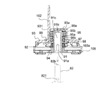
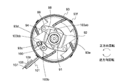
- FIG. 3 is a schematic plan view of the blade unit included in the automatic bread maker according to the first embodiment when viewed from below, and a view when the kneading blade is in a folded posture.
- FIG 3 is a schematic plan view of the blade unit included in the automatic bread maker according to the first embodiment when viewed from below, and a view when the kneading blade is in an open posture.
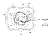
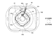
- the figure at the time of seeing the 1st bread container with which the automatic bread maker of 1st Embodiment is provided from the top, and the figure when a kneading blade is in a folding posture The figure at the time of seeing the 1st bread container with which the automatic bread maker of 1st Embodiment is provided from the top, and the figure when a kneading blade is in an open posture
- Sectional drawing for demonstrating the relationship between the hub of the 2nd kneading blade with which the 2nd bread container with which the automatic bread maker of 1st Embodiment is mounted
- the top view for demonstrating the relationship between the hub of the 2nd kneading blade with which the 2nd bread container with which the automatic bread maker of 1st Embodiment is mounted
- the block diagram which shows the structure of the automatic bread maker of 1st Embodiment.
- the schematic diagram which shows each flow of the bread-making course for rice grains, and the bread-making course made from flour performed by the automatic bread maker of the first embodiment The flowchart which shows the start operation
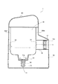
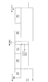
- Schematic sectional view of an automatic bread maker according to a second embodiment The block diagram which shows the structure of the automatic bread maker of 2nd Embodiment. The figure for demonstrating operation
- the block diagram which shows the structure of the automatic bread maker of 3rd Embodiment.
- the flowchart which shows the automatic selection flow of a seasonal course in the automatic bread maker of 3rd Embodiment.
- FIG. 1 is a schematic perspective view showing an external configuration of the automatic bread maker according to the first embodiment.
- an operation unit 20 is provided on a part of the upper surface of a main body 10 (the outer shell of which is formed of, for example, metal or synthetic resin) of an automatic bread maker 1 provided in a substantially rectangular parallelepiped shape. It has been.
- the operation unit 20 includes an input unit 21 including an operation key group in which a user instruction is input by a user operation, contents set by a user instruction input via the input unit 21, an error Etc., and an output unit 22 that displays and the like.
- the operation key group included in the input unit 21 includes, for example, a start key, a cancel key, a timer key, a reservation key, a manufacturing course desired by the user (a manufacturing process for manufacturing bread using rice grains as a starting material, flour (or The selection key etc. which select the manufacturing process which manufactures bread using a rice flour) as a starting material, the manufacturing process etc. which manufacture a cake using wheat flour (or rice flour) as a starting material are included.
- the output unit 22 includes, for example, a liquid crystal display panel, a light emitting element, a speaker, and the like, and notifies the user by outputting sound and light (including images).
- the input unit 21 is an example of the input unit of the present invention
- the output unit 22 is an example of the output unit of the present invention.
- the firing chamber 30 is composed of, for example, a bottom wall 30a made of sheet metal and four side walls 30b (see also FIG. 4 described later).
- the baking chamber 30 has a substantially rectangular box shape in plan view, and its upper surface is open.
- the firing chamber 30 can be opened and closed by a lid 40 provided on the upper part of the main body 10.
- the lid 40 is attached to the back side of the main body 10 with a hinge shaft (not shown), and the firing chamber 30 can be opened and closed by rotating about the hinge shaft as a fulcrum.
- FIG. 1 shows a state where the lid 40 is opened.
- the lid 40 is provided with a viewing window 41 made of heat-resistant glass, for example, so that the inside of the baking chamber 30 can be seen.
- a bread ingredient storage container 42 is attached to the lid 40. This bread ingredient storage container 42 makes it possible to automatically feed some bread ingredients during the bread production process.
- the bread raw material storage container 42 includes a box-shaped container body 42a having a substantially rectangular plane shape, and a container lid 42b that is provided so as to be rotatable with respect to the container body 42a and opens and closes the opening of the container body 42a. .
- the bread ingredient storage container 42 can support the container lid 42b from the outer surface (lower surface) side and maintain the closed state of the opening of the container body 42a, and is moved by an external force to move the container lid 42b to the container lid 42b. There is also provided a movable hook 42c for releasing the engagement.
- An automatic closing solenoid 16 (see FIG. 12 to be described later) is provided in the main body 10 on the lower side of the operation unit 20, and when the automatic closing solenoid is driven, the plunger is adjacent to the lid 40. It protrudes from an opening 10b provided in 10a. Then, the movable hook 42c is moved by a movable member (not shown) movable by the protruding plunger, the engagement between the container lid 42b and the movable hook 42c is released, the container lid 42b is rotated, and the container main body 42a. The opening of is opened. Note that FIG. 1 shows a state where the opening of the container main body 42a is opened.
- the container main body 42a and the container lid 42b are preferably provided with a metal such as aluminum so that powder bread materials (for example, gluten, dry yeast, etc.) stored in the container do not remain in the container. These surfaces are preferably covered with a silicon-based or fluorine-based coating layer, and more preferably configured to be covered with an alumite layer. Moreover, it is preferable that the container main body 42a and the container lid 42b are formed as smoothly as possible without being uneven. Similarly, the inside of the lid 40 (the side on which the bread ingredient storage container 42 is attached) is also configured so that the base material is aluminum and the surface is covered with a coating layer or an alumite layer such as a silicon-based or fluorine-based material. preferable.
- a metal such as aluminum so that powder bread materials (for example, gluten, dry yeast, etc.) stored in the container do not remain in the container.
- These surfaces are preferably covered with a silicon-based or fluorine-based coating layer, and more preferably configured to be
- a flange is provided at the opening side edge of the container main body 42a so that the aforementioned steam or the like does not enter the container, and a packing is provided between the flange and the container lid 42b. (Seal member) 42d is interposed.
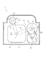
- FIG. 2 is a schematic diagram for explaining the internal configuration of the main body of the automatic bread maker according to the first embodiment.
- FIG. 2 assumes a case where the automatic bread maker 1 is viewed from above, and the lower side of the figure is the front side of the automatic bread maker 1 and the upper side of the figure is the back side.
- a low-speed / high-torque type kneading motor 50 used in the kneading process is fixedly disposed on the right side of the baking chamber 30, and the grinding process is performed behind the baking chamber 30.
- the high-speed rotation type crushing motor 60 used in the above is fixedly arranged.
- the kneading motor 50 and the crushing motor 60 are both shafts.
- the first pulley 52 is fixed to the output shaft 51 protruding from the upper surface of the kneading motor 50.
- the first pulley 52 is connected by a first belt 53 to a second pulley 55 having a diameter larger than that of the first pulley 52 and fixed to the upper side of the first rotating shaft 54.
- a second rotating shaft 57 is provided on the lower side of the first rotating shaft 54 so that the center of rotation is substantially the same as the first rotating shaft 54 (see FIGS. 3A and 3B described later).
- the first rotating shaft 54 and the second rotating shaft 57 are rotatably supported inside the main body 10.
- a clutch 56 that performs power transmission and power interruption is provided between the first rotating shaft 54 and the second rotating shaft 57 (see FIGS. 3A and 3B described later). The configuration of the clutch 56 will be described later.
- a third pulley 58 is fixed to the lower side of the second rotating shaft 57 (see FIGS. 3A and 3B described later).
- the third pulley 58 is provided on the lower side of the firing chamber 30 by the second belt 59 and is fixed to the driving shaft 11 and has a first driving shaft pulley 12 (having substantially the same diameter as the third pulley 58). (See FIGS. 3A and 3B described later).
- the kneading motor 50 itself is a low speed / high torque type, and the rotation of the first pulley 52 is decelerated and rotated by the second pulley 55 (for example, decelerated to 1/5 speed). For this reason, if the kneading motor 50 is driven in a state where the clutch 56 transmits power, the driving shaft 11 rotates at a low speed.
- the first pulley 52, the first belt 53, the first rotating shaft 54, the second pulley 55, the clutch 56, the second rotating shaft 57, the third pulley 58, and the second belt 59 are used.
- the power transmission part comprised by the pulley 12 for 1st drive shafts may be expressed as 1st power transmission part PT1.
- a fourth pulley 62 is fixed to the output shaft 61 protruding from the lower surface of the grinding motor 60.
- the fourth pulley 62 is fixed by a third belt 63 below the second driving shaft pulley 13 (below the first driving shaft pulley 12) fixed to the driving shaft 11; 3A and FIG. 3B).
- the second driving shaft pulley 13 has substantially the same diameter as the fourth pulley 62.
- a high-speed rotating motor is selected as the grinding motor 60, and the rotation of the fourth pulley 62 is maintained at substantially the same speed in the second driving shaft pulley 13. For this purpose, when the grinding motor 60 is driven, the driving shaft 11 rotates at a high speed (for example, 7000 to 8000 rpm).
- the power transmission unit configured by the fourth pulley 62, the third belt 63, and the second driving shaft pulley 13 may be expressed as a second power transmission unit PT2.
- the second power transmission unit PT2 has a configuration that does not have a clutch, and connects the output shaft 61 of the crushing motor 60 and the driving shaft 11 so that power can be transmitted constantly.
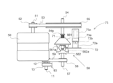
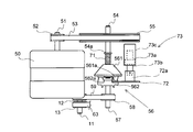
- 3A and 3B are views for explaining a clutch included in the first power transmission unit included in the automatic bread maker of the first embodiment.
- 3A and 3B are diagrams assuming a case of viewing along the direction of the arrow X in FIG. 3A shows a state in which the clutch 56 performs power interruption, and FIG. 3B shows a state in which the clutch 56 transmits power.
- the clutch 56 includes a first clutch member 561 and a second clutch member 562. Then, when the claw 561a provided on the first clutch member 561 and the claw 562a provided on the second clutch member 562 are engaged with each other (the state shown in FIG. 3B), the clutch 56 transmits power. Further, when the two claws 561a and 562a are not engaged with each other (the state shown in FIG. 3A), the clutch 56 cuts off the power. That is, the clutch 56 is a meshing clutch.
- each of the two clutch members 561 and 562 has a circumferential direction (when the first clutch member 561 is seen in plan view from below, or the second clutch member 562 is seen in plan view from above. Assuming the case), six claws 561a and 562a arranged at almost equal intervals are provided, but the number of the claws may be appropriately changed. Moreover, what is necessary is just to select a preferable shape suitably for the shape of nail
- the first clutch member 561 is slidable in the axial direction (vertical direction in FIGS. 3A and 3B) with respect to the first rotating shaft 54 and is not relatively rotatable. It is attached.
- a spring 71 is loosely fitted on the first rotating shaft 54 above the first clutch member 561.
- the spring 71 is disposed so as to be sandwiched between a stopper portion 54a provided on the first rotating shaft 54 and the first clutch member 561, and biases the first clutch member 561 downward.
- the second clutch member 562 is fixed to the upper end of the second rotating shaft 57.
- Switching between the power transmission state and the power cut-off state in the clutch 56 is performed using the arm portion 72 that can be selectively arranged at the lower position and the upper position.
- a part of the arm portion 72 is disposed below the first clutch member 561 and can contact the outer peripheral portion of the first clutch member 561.
- the first clutch member 561 moves downward while being pushed by the urging force of the spring 71.
- the first clutch member 561 and the second clutch member 562 are engaged with each other. That is, when the arm portion 72 is in the lower position, the clutch 56 transmits power.
- the automatic bread maker 1 includes the clutch 56 that performs power transmission and power interruption in the first power transmission unit PT1.
- the second power transmission unit PT2 is not provided with a clutch, for the following reason. That is, even if the kneading motor 50 is driven, the driving shaft 11 is only rotated at a low speed (for example, 180 rpm). For this reason, even if the rotational power for rotating the driving shaft 11 is transmitted to the output shaft of the crushing motor 60, a large load is not applied to the kneading motor 50. And the manufacturing cost of the automatic bread maker 1 is suppressed by adopting the structure in which the clutch is not provided in the second power transmission part PT2 in this way. However, it goes without saying that a configuration in which a clutch is provided in the second power transmission unit PT2 may be adopted.
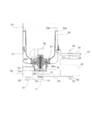
- FIG. 4 is a diagram schematically illustrating the configuration of the baking chamber in which the first bread container is accommodated and its surroundings in the automatic bread maker of the first embodiment.
- FIG. 4 assumes a configuration when the automatic bread maker 1 is viewed from the front side, and the configurations of the baking chamber 30 and the first bread container 80 are generally shown in cross-sectional views. Note that the first bread container 80 used as a bread baking mold as well as the bread raw material is charged into and out of the baking chamber 30.
- a sheathed heater 31 is arranged inside the baking chamber 30 so as to surround the first bread container 80 accommodated in the baking chamber 30.
- the sheathed heater 31 it is possible to heat the bread ingredients in the first bread container 80 (this expression may include bread dough).
- the sheathed heater 31 is an example of the heating unit of the present invention.
- a bread container support portion 14 (for example, made of an aluminum alloy die-cast product) that supports the first bread container 80 is fixed to a location that is substantially at the center of the bottom wall 30a of the baking chamber 30.
- the bread container support portion 14 is formed so as to be recessed from the bottom wall 30a of the baking chamber 30, and the shape of the recess is substantially circular when viewed from above.
- the above-described driving shaft 11 is supported so as to be substantially perpendicular to the bottom wall 30a.
- the first bread container 80 is, for example, an aluminum alloy die-cast product (others may be made of sheet metal or the like), has a bucket-like shape, and is provided on the side edge of the opening.
- a hand handle (not shown) is attached to 80a.
- the horizontal section of the first bread container 80 is a rectangle with rounded corners.
- a concave portion 81 having a substantially circular shape in plan view is formed on the bottom of the first bread container 80 so as to accommodate a part of a blade unit 90 described later in detail.
- a blade rotation shaft 82 extending in the vertical direction is rotatably supported in a state where measures against sealing are taken.
- a container-side coupling member 82a is fixed to the lower end of the blade rotation shaft 82 (projecting outward from the bottom of the first bread container 80).
- a cylindrical pedestal 83 is provided on the outer surface side of the bottom of the first bread container 80, and the first bread container 80 is baked in a state where the pedestal 83 is received by the bread container support part 14. It is accommodated in the chamber 30.
- the pedestal 83 may be formed separately from the first bread container 80 or may be formed integrally with the first bread container 80.
- the aforementioned container side coupling member 82a provided at the lower end of the blade rotation shaft 82; Connection (coupling) with the driving shaft side coupling member 11a fixed to the upper end of the driving shaft 11 is obtained.
- the blade rotation shaft 82 can transmit the rotational power from the driving shaft 11.
- the blade unit 90 is detachably attached to a portion of the blade rotating shaft 82 that protrudes into the first bread container 80 from above.
- the configuration of the blade unit 90 will be described with reference to FIGS. 5, 6, 7A, 7B, 8A, 8B, 9A, and 9B.
- FIG. 5 is a schematic perspective view showing the configuration of the blade unit provided in the automatic bread maker of the first embodiment.
- FIG. 6 is a schematic exploded perspective view showing a configuration of a blade unit provided in the automatic bread maker of the first embodiment.
- 7A and 7B are views showing a configuration of a blade unit provided in the automatic bread maker of the first embodiment, FIG. 7A is a schematic side view, and FIG. 7B is a cross-sectional view at the position AA in FIG. 7A.
- 8A and 8B are schematic plan views of the blade unit included in the automatic bread maker according to the first embodiment when viewed from below, FIG. 8A is a view when the kneading blade is in a folded position, and FIG. 8B is a kneading position.
- FIG. 9A and FIG. 9B are diagrams when the first bread container provided in the automatic bread maker of the first embodiment is viewed from above.
- FIG. 9A is a view when the kneading blade is in a folded position
- FIG. 9B is a view when the kneading blade is in an open position.
- the blade unit 90 is roughly divided into a unit shaft 91, a crushing blade 92 attached to the unit shaft 91 so as not to rotate relative to the unit shaft 91, and a plan view attached to the unit shaft 91 so as to be relatively rotatable and covering the crushing blade 92.
- a substantially circular dome-shaped cover 93 and a kneading blade 101 attached to the dome-shaped cover 93 so as to be relatively rotatable are configured (see, for example, FIGS. 5, 6, 7A and 7B).
- the crushing blade 92 is located at a position slightly above the bottom surface of the recess 81 of the first bread container 80. Further, almost the entire grinding blade 92 and the dome-shaped cover 93 are accommodated in the recess 81.
- the unit shaft 91 is a substantially cylindrical member formed of a metal such as a stainless steel plate, for example, and has an opening at one end (the lower end in FIGS. 6 and 7B), and the inside is hollow. That is, the insertion shaft 91c is formed in the unit shaft 91 (see FIG. 7B).
- a pair of notches 91a are formed on the lower side (opening side) of the side wall of the unit shaft 91 so as to be symmetrically arranged with respect to the rotation center of the unit shaft 91 (see, for example, FIG. 6). 6 shows only one of them).
- the upper inner surface of the unit shaft 91 is engaged with the convex portion 82b provided at the center of the upper surface (substantially circular) of the blade rotation shaft 82 (shown by a broken line).
- a recess 91b is formed at the center. Accordingly, the blade unit 90 can be easily attached to the blade rotation shaft 82 in a state where the centers of the unit shaft 91 and the blade rotation shaft 82 are aligned. For this reason, unnecessary rattling during rotation of the blade is suppressed.
- the convex portion 82b is provided on the blade rotating shaft 82 side and the concave portion 91b is provided on the unit shaft 91 side, but conversely, the concave portion is provided on the blade rotating shaft 82 side and the unit shaft 91 side is provided.
- a configuration in which a convex portion is provided may be employed.
- the pulverizing blade 92 for pulverizing grains is formed of, for example, a stainless steel plate, and the shape thereof is, for example, an airplane propeller. As shown in FIG. 6, an opening 923 a having a substantially rectangular shape in plan view is formed at the center of the crushing blade 92. The crushing blade 92 is attached from the lower side of the unit shaft 91 so that the unit shaft 91 is fitted into the opening 923a.
- the lower side of the unit shaft 91 has a shape that is obtained by scraping the side surface of the cylinder, and is substantially the same shape (substantially rectangular shape) as the opening 923a of the grinding blade 92 when viewed from below.
- the area when the lower side of the unit shaft 91 is viewed from below is slightly smaller than the opening 923a. Since such a shape is adopted, the grinding blade 92 is attached to the unit shaft 91 so as not to be relatively rotatable. Since the stopper member 94 for preventing the retaining member 94 is fitted into the unit shaft 91 on the lower side of the pulverizing blade 92, the pulverizing blade 92 does not fall off the unit shaft 91.
- the dome-shaped cover 93 disposed so as to surround and cover the crushing blade 92 is made of, for example, an aluminum alloy die-cast product, and a bearing 95 (in this embodiment, a rolling bearing is used on the inner surface side thereof. ) (See FIG. 7B) is formed.
- the dome-shaped cover 93 has a configuration in which a substantially cylindrical convex portion 93a is formed at the center when viewed from the outer surface.
- the opening is not formed in the convex part 93a, and the bearing 95 accommodated in the accommodating part 931 is in the state in which the side surface and the upper surface are enclosed by the wall surface of the accommodating part 931.
- the inner ring 95a is attached to the unit shaft 91 so as not to rotate relative to the bearing 95 with the retaining rings 96a and 96b arranged on the upper and lower sides (the unit shaft 91 is press-fitted into a through hole inside the inner ring 95a. ing).
- the bearing 95 is press-fitted into the housing portion 931 so that the outer wall of the outer ring 95b is fixed to the side wall of the housing portion 931.
- the dome-shaped cover 93 is attached to the unit shaft 91 so as to be rotatable relative to the bearing 95 (the inner ring 95a rotates relative to the outer ring 95b).
- the housing portion 931 of the dome-shaped cover 93 is made of, for example, a silicon-based material so that foreign matter (for example, liquid used when pulverizing grain grains or paste-like material obtained by pulverization) does not enter the bearing 95 from the outside.
- a seal material 97 formed of a fluorine-based material and a metal seal cover 98 that holds the seal material 97 are press-fitted from the lower side of the bearing 95.
- the seal cover 98 is fixed to the dome-shaped cover 93 with a rivet 99 so that the fixing to the dome-shaped cover 93 is ensured.
- fixing with the rivet 99 may not be performed, it is preferable to configure as in the present embodiment in order to obtain reliable fixing.
- the sealing material 97 and the sealing cover 98 function as sealing means.
- the seal cover 98 is preferably coated with a fluorine-based coating material or the like. In particular, it is preferable to use a silver paint because the coating is difficult to peel off and even if it is peeled off, it is difficult to stand out.
- a kneading blade 101 (for example, aluminum) in a planar shape is formed by a support shaft 100 (see FIG. 6) disposed so as to extend in a vertical direction at a location adjacent to the convex portion 93 a. (Made of die-cast alloy product) is attached.
- the kneading blade 101 is attached to the support shaft 100 so as not to be relatively rotatable, and moves together with the support shaft 100 attached to the dome-shaped cover 93 so as to be relatively rotatable. In other words, the kneading blade 101 is attached to the dome-shaped cover 93 so as to be relatively rotatable.
- FIG. 5 On one surface near the tip of the kneading blade 101 (assuming a portion that draws the largest circle when the kneading blade 101 is rotated about the support shaft 100), FIG. 5, FIG. 6, FIG. 7A, FIG. As shown in FIGS. 8A, 8B, 9A, and 9B, a cushioning material 107 is attached.
- the buffer material 107 is provided so as to slightly protrude from the tip of the kneading blade 101 (see, for example, FIG. 9B).
- the buffer material 107 is fixed in a state where the buffer material 107 is sandwiched between one surface of the kneading blade 101 and the fixing plate 108 and obtained by caulking the rivet 109 inserted from the other surface side of the kneading blade 101. ing.
- the number of rivets 109 is two, but it goes without saying that the number is not limited.
- the buffer material 107 is disposed so as not to directly contact the first bread container 80 (inner wall) when the kneading blade 101 is in an open posture, which will be described in detail later. If the kneading blade 101 and the first bread container 80 are in direct contact with each other, damage may occur due to interference between them, and the buffer material 107 is provided to prevent such damage. Yes.
- the surfaces of the first bread container 80 and the kneading blade 101 are coated with fluorine.
- the buffer material 107 of the present embodiment is provided so that the fluorine coating is not peeled off by contact between the kneading blade 101 and the first bread container 80.
- the material constituting the cushioning material 107 is preferably a material softer than the coating material so as not to peel off the fluorine coating.
- silicone rubber or TPE Thermoplastic Elastomers
- the buffer material 107 also functions as a soundproofing measure, which will be described later. In the following description, the buffer material 107 may be regarded as a part of the kneading blade 101.
- the complementary kneading blade 102 (for example, made of an aluminum alloy die cast product) is fixedly arranged on the outer surface of the dome-shaped cover 93 so as to be aligned with the kneading blade 101.
- the complementary kneading blade 102 is not necessarily provided, but is preferably provided in order to increase the kneading efficiency in the kneading process of kneading the bread dough.
- the kneading blade 101 rotates about the axis of the support shaft 100 together with the support shaft 100, and has two postures, a folded posture shown in FIGS. 5, 7A, 8A and 9A, and an open posture shown in FIGS. 8B and 9B. Take. In the folded position, the protrusion 101a (see FIG. 6) hanging from the lower edge of the kneading blade 101 comes into contact with the first stopper portion 93b provided on the upper surface (outer surface) of the dome-shaped cover 93.
- the kneading blade 101 cannot further rotate counterclockwise (assuming the case viewed from above) with respect to the dome-shaped cover 93. In this folded position, the tip of the kneading blade 101 protrudes slightly from the dome-shaped cover 93.
- the tip of the kneading blade 101 is moved to the open posture shown in FIG. Protrudes greatly from the dome-shaped cover 93.
- the opening angle of the kneading blade 101 in this opening posture is limited by the second stopper portion 93 c (see FIG. 8B) provided on the inner surface of the dome-shaped cover 93.
- the complementary kneading blade 102 is aligned with the kneading blade 101 as shown in FIGS. 5 and 7A, for example.
- the size becomes larger.
- a first engagement body 103 a constituting the cover clutch 103 is attached to the unit shaft 91 between the pulverization blade 92 and the seal cover 98.
- a substantially rectangular opening 103aa is formed in the first engagement body 103a made of, for example, zinc die casting, and the first rectangular body 103 in the lower side of the unit shaft 91 is fitted into the opening 103aa so that the first The engaging body 103a is attached to the unit shaft 91 so as not to be relatively rotatable.
- the first engaging body 103a is fitted from the lower side of the unit shaft 91 prior to the crushing blade 92, and the stopper member 94 prevents the unit shaft 91 from dropping off together with the crushing blade 92.
- the washer 104 is disposed between the first engagement body 103a and the seal cover 98 in consideration of prevention of deterioration of the first engagement body 103a.
- the washer 104 is not necessarily provided. It does not have to be provided.
- a second engagement body 103b constituting the cover clutch 103 is attached to the lower side of the support shaft 100 to which the kneading blade 101 is attached.
- a substantially rectangular opening 103ba is formed in the second engaging body 103b made of zinc die casting, and the second engaging member is fitted into the opening 103ba by fitting a substantially rectangular portion in plan view on the lower side of the support shaft 100.
- the united body 103b is attached to the support shaft 100 so as not to be relatively rotatable.
- the washer 105 is arranged on the upper side of the second engagement body 103b in consideration of prevention of deterioration of the second engagement body 103b. However, the washer 105 is not necessarily provided.
- the cover clutch 103 composed of the first engagement body 103a and the second engagement body 103b functions as a clutch for switching whether or not to transmit the rotational power of the blade rotation shaft 82 to the dome-shaped cover 93.
- the cover clutch 103 is a rotation direction of the blade rotation shaft 82 when the kneading motor 50 rotates the driving shaft 11 (this rotation direction is referred to as “forward rotation”. In FIGS. 8A and 8B, the rotation is counterclockwise. 9A and 9B, the rotational power of the blade rotation shaft 82 is transmitted to the dome-shaped cover 93. Conversely, the rotation direction of the blade rotation shaft 82 when the crushing motor 60 rotates the drive shaft 11 (this rotation direction is referred to as “reverse rotation”. FIGS. 8A and 8B rotate clockwise, and FIGS. 9A and 9B show rotation directions). Then, the cover clutch 103 does not transmit the rotational power of the blade rotating shaft 82 to the dome-shaped cover 93.
- the engagement portion 103bb of the second engagement body 103b is the engagement portion 103ab of the first engagement body 103a (although there are two in this embodiment). It is an angle that interferes with the rotation trajectory (see Fig. 8A). Therefore, when the blade rotation shaft 82 rotates in the forward direction, the first engagement body 103 a and the second engagement body 103 b are engaged, and the rotational power of the blade rotation shaft 82 is transmitted to the dome-shaped cover 93.
- the engagement portion 103bb of the second engagement body 103b deviates from the rotation trajectory of the engagement portion 103ab of the first engagement body 103a. (See the broken line in FIG. 8B). For this reason, even if the blade rotation shaft 82 rotates, the first engagement body 103a and the second engagement body 103b are not engaged. Accordingly, the rotational power of the blade rotation shaft 82 is not transmitted to the dome-shaped cover 93.
- the dome-shaped cover 93 is formed with a window 93d that communicates the space inside the cover and the space outside the cover.
- the window 93d is arranged at a height equal to or higher than the grinding blade 92.
- a total of four windows 93d are arranged at intervals of 90 °, but other numbers and arrangement intervals can be selected.
- each rib 93e extends obliquely from the vicinity of the center of the dome-shaped cover 93 to the outer peripheral annular wall with respect to the radial direction, and the four ribs 93e form a kind of bowl shape. Moreover, each rib 93e is curving so that the side which faces the bread raw material pressed toward it may become convex.
- a removable guard 106 is attached to the lower surface of the dome-shaped cover 93.
- the guard 106 covers the lower surface of the dome-shaped cover 93 and prevents the user's finger from approaching the grinding blade 92.
- the guard 106 is formed of, for example, an engineering plastic having heat resistance, and can be a molded product such as PPS (polyphenylene sulfide).
- PPS polyphenylene sulfide
- a ring-shaped hub 106a through which a stopper member 94 fixed to the unit shaft 91 is passed.
- a ring-shaped rim 106b is provided at the periphery of the guard 106.
- the hub 106a and the rim 106b are connected by a plurality of spokes 106c. Between the spokes 106c, there is an opening 106d through which the grain to be crushed by the pulverizing blade 92 is passed.
- the opening 106d has a size that prevents a finger from passing through.
- the guard 106 is shaped like an outer blade of a rotary electric razor, and the grinding blade 92 is shaped like an inner blade.
- a total of four columns 106e are integrally formed at the periphery of the rim 106b at intervals of 90 °.
- a horizontal groove 106ea having one end dead end is formed on a side surface of the pillar 106e facing the center side of the guard 106.
- the guard 106 is attached to the dome-shaped cover 93 by engaging the grooves 106 ea with the projections 93 f formed on the outer periphery of the dome-shaped cover 93 (all four are arranged at intervals of 90 °).
- the groove 106ea and the protrusion 93f are provided so as to constitute a bayonet connection.
- the crushing blade 92 and the kneading blade 101 are incorporated into one unit (blade unit 90), the handling thereof is convenient.
- the user can easily pull out the blade unit 90 from the blade rotating shaft 82, and can easily clean the blade after the bread making operation.
- the pulverizing blade 92 provided in the blade unit 90 is detachably attached to the unit shaft 91, and is easily mass-produced and has excellent maintainability such as blade replacement.
- the bearing 95 since a liquid such as water is put in the first bread container 80, the bearing 95 has a sealed structure so that the liquid does not enter the bearing 95. preferable.
- the sealing means (the sealing material 97 and the sealing material 97 and the sealing material only on the inner surface side of the dome-shaped cover 93) If the cover 98) is provided, a structure for sealing the bearing 95 is obtained. For this reason, it is not necessary to provide sealing means above and below the bearing 95, and the seal structure of the bearing 95 can be downsized. For this reason, in the automatic bread maker 1, it is possible to suppress an adverse effect on the shape of the baked bread (for example, the bottom surface of the bread is greatly recessed).
- FIG. 10 is a partial cross-sectional view illustrating a schematic configuration of the automatic bread maker according to the first embodiment, and is a diagram illustrating a configuration when a second bread container is used.
- FIG. 10 assumes the case where the automatic bread maker is viewed from the front side.
- the description of the same configuration as that in the case of using the first bread container 80 is omitted when there is no need for description.
- the second bread container 110 (for example, made of sheet metal) has a bucket-like shape like the first bread container 80, and a handle (not shown) is provided for the hook 110a provided on the side edge of the opening. Is attached.
- the second bread container 110 also has a horizontal section that is a rectangle with rounded corners.
- a recess 81 like the first bread container 80 is not formed at the bottom of the second bread container 110. This is related to the fact that when the second bread container 110 is used, there is no crushing step and it is not necessary to attach the crushing blade 92.
- the second bread container 110 does not need to be provided with the recess 81, and therefore has a lower height than the first bread container 80.
- the second blade rotating shaft 111 extending in the vertical direction is supported at the center of the bottom of the second bread container 110 in a state where a countermeasure against sealing is taken.
- a container-side coupling member 111a is fixed to the lower end of the second blade rotating shaft 111 (external to the second bread container 110).
- a cylindrical pedestal 112 is provided on the outer bottom surface of the second bread container 110, and the second bread container 110 is in a baking chamber in a state where the pedestal 112 is received by the bread container support part 14. 30 is arranged inside.
- the method for joining the pedestal 112 and the bread container support 14 is the same as the method for joining the pedestal 83 of the first bread container 80 and the bread container support 14. Further, the coupling between the pedestal 112 and the bread container support portion 14 connects the container side coupling member 111 a provided on the second blade rotation shaft 111 and the driving shaft side coupling member 11 a fixed to the driving shaft 11. (Coupling) is also achieved. By this coupling, the second blade rotating shaft 111 can transmit a rotational force from the driving shaft 11.
- a second kneading blade 120 (for example, an aluminum alloy die cast product) is attached to the upper end of the second blade rotating shaft 111.
- the second kneading blade 120 has a shape such that the above-described kneading blade 101 and the complementary kneading blade 102 (see, for example, FIG. 5) are integrated, and the hub 121 rotates to the upper end of the second blade rotating shaft 111. Linked impossible.
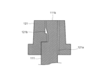
- FIG. 11A and 11B are views for explaining the relationship between the hub of the second kneading blade and the second blade rotation shaft in the second bread container, FIG. 11A is a sectional view, and FIG. 11B is a top view. is there.
- the central hole of the hub 121 of the second kneading blade 120 is a circular hole 121a at a predetermined height from the lower end, and the upper part is a D-shaped hole 121b.
- the D-shaped hole portion 121 b has a step structure in which a lower portion corresponding to the D-shaped string projects toward the center of the second blade rotation shaft 111.
- the second blade rotating shaft 111 has a circular cross section up to a point where a distance is left to the upper end, and the upper portion is a D-shaped cross section 111b. Contrary to the D-shaped hole portion 121b, the D-shaped cross-sectional portion 111b has a stepped structure in which an upper portion of a portion that contacts the D-shaped string protrudes.
- the hub 121 of the second kneading blade 120 is non-rotatably connected to the second blade rotating shaft 111. Since the hub 121 and the second blade rotating shaft 111 are sufficiently fitted, the second blade rotating shaft 111 can be passed through the hub 121 without any problem to obtain the overhanged state.
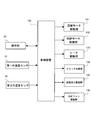
- FIG. 12 is a block diagram illustrating a configuration of the automatic bread maker according to the first embodiment.
- the control operation in the automatic bread maker 1 is performed by the control device 130.
- the control device 130 is configured by a microcomputer including a central processing unit (CPU), a read only memory (ROM), a random access memory (RAM), an input / output (I / O) circuit unit, and the like. .
- the control device 130 is preferably disposed at a position that is not easily affected by the heat of the baking chamber 30.
- the control device 130 is provided with a time measuring function, and temporal control in the bread manufacturing process is possible.
- the control device 130 includes an operation unit 20 including the input unit 21 and the output unit 22 described above, a temperature sensor 15 that detects the temperature of the baking chamber 30, a kneading motor drive circuit 131, a pulverization motor drive circuit 132, and a heater.
- the drive circuit 133, the first solenoid drive circuit 134, and the second solenoid drive circuit 135 are electrically connected.
- the temperature sensor 15 is composed of, for example, a thermocouple, a thermistor, etc., and detects the temperature of the baking chamber 30 and inputs it to the control device 130.
- the kneading motor driving circuit 131 is a circuit for controlling the driving of the kneading motor 50 under a command from the control device 130.
- the grinding motor drive circuit 132 is a circuit for controlling the driving of the grinding motor 60 under a command from the control device 130.
- the heater drive circuit 133 is a circuit for controlling the operation of the sheathed heater 31 under a command from the control device 130.
- the first solenoid drive circuit 134 controls driving of the automatic charging solenoid 16 that is driven when a part of the bread ingredients is automatically charged in the course of the bread manufacturing process under a command from the control device 130. Circuit.
- the second solenoid drive circuit 135 controls the drive of the clutch solenoid 73 (see FIGS. 3A and 3B) that switches the state of the clutch 56 (see FIGS. 3A and 3B) under a command from the control device 130. Circuit.
- the control device 130 reads a program related to a bread manufacturing course (breadmaking course) stored in a ROM or the like based on an input signal from the input unit 21 of the operation unit 20, and the kneading motor via the kneading motor driving circuit 131.
- the automatic bread maker 1 can also produce food other than bread.
- the control device 130 manufactures a cake stored in a ROM or the like based on an input signal from the input unit 21 of the operation unit 20 (cake manufacturing course).
- the second kneading motor 120 is controlled by the kneading motor 50 via the kneading motor driving circuit 131 and the heating operation by the sheathed heater 31 is controlled via the heater driving circuit 133.
- control device 130 performs a heating operation by the sheathed heater 31 via the heater drive circuit 133 while confirming the temperature detected by the temperature sensor 15. Thereby, the control apparatus 130 ensures that the heating operation (temperature control of the baking chamber 30) is performed with high accuracy.
- the control device 130 also checks the temperature detected by the temperature sensor 15 when starting the manufacturing process, and performs a control operation accordingly. Details of the control operation at the start of the manufacturing process by the control device 130 will be described later.
- FIG. 13 is a schematic diagram showing the flow of the rice grain bread course and the flour bread course executed by the automatic bread maker 1.
- Fig.13 (a) shows the flow of the bread-making course for rice grains
- FIG.13 (b) shows the bread-making course made of wheat flour.
- the dipping process, the crushing process, the pause process, the kneading process, the fermentation process, and the baking process are sequentially performed in this order. To be executed.
- the user attaches the blade unit 90 to the blade rotation shaft 82 by covering the blade rotation shaft 82 of the first bread container 80 with the unit shaft 91. Then, the user weighs rice grains, water, and seasonings (eg, salt, sugar, shortening, etc.) by a predetermined amount and puts them in the first bread container 80. In addition, the user weighs the bread ingredients that are automatically added during the bread manufacturing process and puts them in the container body 42 a of the bread ingredient storage container 42.
- the container lid 42b is supported by the movable hook 42c so that the opening of the container main body 42a is closed by the container cover 42b.
- the bread raw material accommodated in the bread raw material storage container 42 gluten, dry yeast, etc. are mentioned, for example.
- gluten for example, at least one of flour, thickener (eg, guar gum), and upper fresh powder may be stored in the bread ingredient storage container 42.
- only dry yeast may be stored in the bread raw material storage container 42 without using gluten, wheat flour, thickener, super fresh powder or the like.
- salt, sugar and shortening seasonings such as salt, sugar and shortening are stored in the bread ingredient storage container 42 together with, for example, gluten and dry yeast so as to be automatically introduced during the bread manufacturing process. It may be.
- the bread raw material previously put into the first bread container 80 is rice grains and water (a liquid having a taste component such as dashi soup, a liquid containing fruit juice or alcohol, etc. instead of mere water). Good).
- the control apparatus 130 starts control operation
- the dipping process is started by a command from the control device 130.
- the bread raw material previously put in the first bread container 80 is set in a static state, and this static state is maintained for a predetermined time (30 minutes in this embodiment).
- This dipping process is a process aimed at making the rice grains easy to be pulverized to the core in the subsequent pulverization process by adding water to the rice grains.
- the water absorption rate of rice grains varies depending on the temperature of the water. If the water temperature is high, the water absorption rate increases, and if the water temperature is low, the water absorption rate decreases. For this reason, you may make it fluctuate
- the grinding blade 92 may be rotated at the initial stage of the dipping process, and further, the grinding blade 92 may be intermittently rotated thereafter. If it does in this way, the surface of a rice grain can be damaged, and the liquid absorption efficiency of a rice grain will be improved.
- the dipping process is terminated by a command from the control device 130, and the crushing process for crushing the rice grains is started.
- the crushing blade 92 is rotated at a high speed (for example, 7000 to 8000 rpm) in a mixture containing rice grains and water.
- the control device 130 controls the crushing motor 60 to rotate the blade rotation shaft 82 in the reverse direction (clockwise rotation in FIGS. 8A and 8B, and counterclockwise rotation in FIGS. 9A and 9B). Since the blade portion (cutting blade) of the crushing blade 92 is moved forward in the rotation direction by the reverse rotation of the blade rotation shaft 82, the crushing function can be obtained by the reverse rotation.
- control device 130 drives the clutch solenoid 73 before driving the grinding motor 60 so that the clutch 56 shuts off the power (the state shown in FIG. 3A).
- the dome-shaped cover 93 also starts to rotate following the rotation of the blade rotation shaft 82.
- the rotation of the cover 93 is immediately blocked (stopped). It is preferable that the pulverizing blade 92 is rotated at a low speed in the initial stage of the pulverization process and then rotated at a high speed.
- the rotation direction of the dome-shaped cover 93 accompanying the rotation of the blade rotation shaft 82 for rotating the grinding blade 92 is the counterclockwise direction in FIGS. 9A and 9B, and the kneading blade 101 has been folded until then (see FIG. 9A).
- the resistance is changed to the open posture (posture shown in FIG. 9B) due to the resistance received from the mixture containing rice grains and water.
- the engagement portion 103bb of the second engagement body 103b deviates from the rotation trajectory (see the broken line in FIG. 8B) of the engagement portion 103ab of the first engagement body 103a.
- the cover clutch 103 disconnects the blade rotation shaft 82 from the dome-shaped cover 93.
- a part of the kneading blade 101 in the open posture (more precisely, the buffer material 107 provided on the front end side) is formed on the inner wall (specifically, the first bread container 80).
- the rotation of the dome-shaped cover 93 is prevented (stopped) in order to come into contact with the bowl-shaped convex part 80b provided on the inner wall of the first bread container 80 in order to improve the grinding efficiency.
- the pulverization of the rice grains in the pulverization step is performed in a state in which water is soaked in the rice grains by the previously performed immersion step, so that the rice grains can be easily pulverized to the core.
- the rotation of the pulverizing blade 92 in the pulverization step is intermittent. This intermittent rotation is performed, for example, in a cycle of rotating for 30 seconds and stopping for 5 minutes, and this cycle is repeated 10 times. In the last cycle, the stop for 5 minutes is not performed.
- the rotation of the crushing blade 92 may be continuous rotation, but for the purpose of, for example, preventing the raw material temperature in the first bread container 80 from becoming too high, it is preferable to perform intermittent rotation.
- the pulverization of the rice grains is performed in the dome-shaped cover 93 that has stopped rotating, and therefore the possibility that the rice grains scatter out of the first bread container 80 is low. Further, the rice grains entering the dome-shaped cover 93 from the opening 106d of the guard 106 in the rotation stopped state are sheared between the stationary spoke 106c and the rotating pulverizing blade 92, so that the pulverization can be performed efficiently. Further, the rib 93e provided on the dome-shaped cover 93 suppresses the flow of the mixture containing rice grains and water (flow in the same direction as the rotation of the grinding blade 92), so that the grinding can be performed efficiently.
- the mixture containing the pulverized rice grains and water is guided in the direction of the window 93d by the ribs 93e, and discharged from the window 93d to the outside of the dome-shaped cover 93. Since the rib 93e is curved so that the side facing the mixture pressing toward it is convex, the mixture hardly stays on the surface of the rib 93e and flows smoothly toward the window 93d. Further, instead of the mixture being discharged from the inside of the dome-shaped cover 93, the mixture existing in the space above the concave portion 81 enters the concave portion 81 and passes through the opening portion 106d of the guard 106 from the concave portion 81. Enter the cover 93. Since the pulverization by the pulverization blade 92 is performed while being circulated as described above, the pulverization can be performed efficiently.
- the crushing process is completed in a predetermined time (in this embodiment, 50 minutes).
- the grain size of the pulverized powder may vary depending on the hardness of the rice grains and the environmental conditions.
- the end of the pulverization process may be determined based on the magnitude of the load of the pulverization motor 60 (for example, it can be determined by the control current of the motor).
- the pause process is executed according to a command from the control device 130.
- This pause process is provided as a cooling period during which the temperature of the contents in the first bread container 80 raised by the crushing process is lowered.
- the reason for lowering the temperature is that the next kneading step is carried out at a temperature at which the yeast is active (for example, around 30 ° C.).
- the pause process is a predetermined time (30 minutes), but in some cases, the pause process may be performed until the temperature of the first bread container 80 reaches a predetermined temperature. I do not care.
- the kneading process is started by a command from the control device 130.
- the control device 130 drives the clutch solenoid 73 so that the clutch 56 transmits power (the state shown in FIG. 3B).
- the controller 130 starts driving the kneading motor 50 to rotate the blade rotation shaft 82 in the forward direction (counterclockwise rotation in FIGS. 8A and 8B and clockwise rotation in FIGS. 9A and 9B).
- the grinding blade 92 When the blade rotation shaft 82 is rotated in the forward direction, the grinding blade 92 is also rotated in the forward direction. In this case, the pulverizing blade 92 rotates with the blade portion (cutting blade) behind in the rotational direction, and does not exhibit the pulverizing function.
- the rotation of the grinding blade 92 causes the bread ingredients around the grinding blade 92 to flow in the forward direction (clockwise in FIGS. 9A and 9B).
- the dome-shaped cover 93 moves in the forward direction, the kneading blade 101 receives resistance from the non-flowing bread ingredients and changes the angle from the open position (see FIG. 9B) to the folded position (see FIG. 9A). Go.
- the engaging portion 103bb of the second engaging body 103b has an angle that interferes with the rotation trajectory (see the broken line in FIG. 8A) of the engaging portion 103ab of the first engaging body 103a.
- the cover clutch 103 connects the blade rotation shaft 82 and the dome-shaped cover 93, and the dome-shaped cover 93 enters a state of being driven in earnest by the blade rotation shaft 82.
- the dome-shaped cover 93 and the kneading blade 101 in the folded position rotate together with the blade rotation shaft 82 in the forward direction.
- the rotation of the blade rotation shaft 82 at the initial stage of the kneading process is preferably intermittent rotation or low speed rotation.
- the complementary kneading blade 102 is arranged on the extension of the kneading blade 101, so that the kneading blade 101 is enlarged and the bread raw material is pressed strongly. It is. For this reason, the dough can be kneaded firmly.
- the rotation of the kneading blade 101 (this term is used as an expression including the complementary kneading blade 102 in the folded position, the same applies hereinafter) is very slow in the initial stage of the kneading process, and the speed is increased stepwise.
- Control is performed by the control device 130 as described above.
- the control device 130 drives the automatic charging solenoid 16 so that the movable hook 42c of the bread ingredient storage container 42 supports the container lid 42b. Let go. Thereby, the opening of the container main body 42a is opened, and for example, bread ingredients such as gluten and dry yeast are automatically charged into the first bread container 80.
- the bread raw material storage container 42 is provided with a coating layer inside the container body 42a and the container lid 42b to improve slipping, and is devised so that there is no uneven portion inside. Yes. Furthermore, the situation where the bread raw material is caught by the packing 42d is also suppressed by the device for arranging the packing 42d. For this reason, the automatic charging is completed with almost no bread ingredients remaining in the bread ingredient storage container 42.
- the bread ingredients stored in the bread ingredient storage container 42 are charged while the kneading blade 101 is rotating.
- the present invention is not limited to this, and the kneading blade 101 is stopped. You may decide to throw in in the state which is carrying out.
- the kneading blade 101 rotates the bread ingredients into one dough having a predetermined elasticity. It will be crafted. When the kneading blade 101 shakes the dough and knocks it against the inner wall of the first bread container 80, an element of “kneading” is added to the kneading. As the kneading blade 101 rotates, the dome-shaped cover 93 also rotates.
- the rib 93e formed on the dome-shaped cover 93 also rotates, so that the bread material in the dome-shaped cover 93 is quickly discharged from the window 93d and the kneading blade 101 kneads the bread. Assimilate into a lump of material.
- the guard 106 also rotates in the forward direction together with the dome-shaped cover 93.
- the spoke 106c of the guard 106 has a shape in which the center side of the guard 106 precedes and the outer peripheral side of the guard 106 follows when rotating in the forward direction.
- the guard 106 rotates in the forward direction to push the bread ingredients inside and outside the dome-shaped cover 93 outward with the spokes 106c. Thereby, the ratio of the raw material used as a waste after baking bread can be reduced.
- the pillar 106e of the guard 106 has a side surface 106eb (see FIG. 6) which is the front surface in the rotation direction when the guard 106 rotates in the forward direction, and is inclined upward. Bread ingredients are sprung upward on the front surface of the column 106e. For this reason, the ratio of the raw material which becomes waste after baking bread can be reduced.
- a predetermined time (10 minutes in this embodiment) obtained experimentally as a time for obtaining bread dough having a desired elasticity is employed as the time for the kneading process.
- the time of the kneading process is constant, the degree of bread dough may vary depending on the environmental temperature or the like. For this reason, for example, a configuration in which the end point of the kneading process is determined based on the magnitude of the load of the kneading motor 50 (for example, it can be determined by the control current of the motor) may be used.
- ingredients for example, raisins, nuts, cheese, etc.
- the ingredients may be introduced during the kneading process.
- the fermentation process is started by a command from the control device 130.
- the control device 130 controls the sheathed heater 31 to maintain the temperature of the baking chamber 30 at a temperature at which fermentation proceeds (for example, 38 ° C.). Then, the dough is left for a predetermined time (in this embodiment, 60 minutes) in an environment in which fermentation proceeds.
- the kneading blade 101 may be rotated to perform degassing or rounding of the dough.
- the firing process is started by a command from the control device 130.
- the control device 130 controls the sheathed heater 31 to raise the temperature of the baking chamber 30 to a temperature suitable for baking (for example, 125 ° C.). Then, the control device 130 performs control so that the bread is baked for a predetermined time (in this embodiment, 50 minutes) in the baking environment.
- the end of the firing process is notified to the user by, for example, a display on the output unit 22 of the operation unit 20 or a notification sound.
- the user detects the completion of bread making, the user opens the lid 40 and takes out the first bread container 80 to complete the bread production.
- the bread in the first bread container 80 can be taken out, for example, by directing the opening of the first bread container 80 obliquely downward. Simultaneously with the removal of the bread, the blade unit 90 attached to the blade rotation shaft 82 is also removed from the first bread container 80. At the bottom of the bread, the burn marks of the kneading blade 101 of the blade unit 90 and the complementary kneading blade 102 (projecting upward from the recess 81 of the first bread container 80) remain. However, since the dome-shaped cover 93 and the guard 106 are accommodated in the recess 81, they are prevented from leaving a large burn mark on the bottom of the bread.
- a kneading (kneading) process in a bread course made of flour, a kneading (kneading) process, a primary fermentation process, a degassing process, a dough resting process (also called bench time or negakashi), and dough A rounding process, a shaping fermentation process, and a baking process are sequentially performed in this order.
- the user attaches the second kneading blade 120 to the second bread container 110. Then, after putting a predetermined amount of water into the second bread container 110, put a predetermined amount of flour (strong flour), salt, sugar, shortening, and finally, the second pan so that the dry yeast does not touch the water. Place in container 110. Note that the amount of seasonings such as salt, sugar, and shortening may be appropriately changed according to the user's preference. Thereafter, the user puts the second bread container 110 into the baking chamber 30, closes the lid 40, selects a bread course made of flour by the operation unit 20, and presses the start key. Thereby, the bread
- the kneading process is started by a command from the control device 130.
- the control device 130 controls the kneading motor 50 to rotate the second blade rotating shaft 111 in the forward direction.
- the second kneading blade 120 is rotated at a low speed and a high torque.
- the rotation of the second kneading blade 120 is controlled by the control device 130 so as to be very slow at the initial stage of the kneading process, for example, so that the speed is increased stepwise.
- Rotation of the second kneading blade 120 causes the bread ingredients in the second bread container 110 to be kneaded and kneaded into one dough having a predetermined elasticity.
- an element of “kneading” is added to the kneading. This kneading step is performed for a predetermined time (12 minutes in the present embodiment) experimentally obtained as a time for obtaining bread dough having a desired elasticity.
- ingredients for example, raisins, nuts, cheese, etc.
- the ingredients may be introduced during the kneading process.
- a primary fermentation process for fermenting the bread dough is started according to a command from the control device 130.
- the control device 130 controls the sheathed heater 31 to maintain the temperature of the baking chamber 30 at a predetermined temperature (32 ° C. in this embodiment) at which fermentation proceeds.
- the primary fermentation process is performed for 48 minutes and 50 seconds.
- a degassing process for degassing the dough contained in the bread dough is started according to a command from the control device 130.
- the control device 130 controls the drive of the kneading motor 50 to continuously rotate the second kneading blade 120 for a predetermined time (in this embodiment, 10 seconds).
- the control device 130 also controls the sheathed heater 31 to maintain the temperature of the firing chamber 30 at a predetermined temperature.
- a dough resting process (bench time; sometimes referred to as “nekashi”) for resting the dough according to a command from the control device 130 is executed.
- the control device 130 controls the sheathed heater 31 to maintain the temperature of the baking chamber 30 at a predetermined temperature (32 ° C. in the present embodiment).
- the bench time is performed in this embodiment (35 minutes and 30 seconds).
- a dough rounding process for rounding the bread dough is started according to a command from the control device 130.
- the control device 130 controls the drive of the kneading motor 50 to rotate the second kneading blade 120.
- the second kneading blade 120 is rotated very slowly for a predetermined time (1 minute 30 seconds in this embodiment).
- a molding fermentation process is performed in which the bread dough is fermented again according to a command from the control device 130.
- the control device 130 controls the sheathed heater 31 to set the temperature of the baking chamber 30 to a predetermined temperature (38 ° C. in this embodiment) at which fermentation proceeds, and this state for a predetermined time (in this embodiment). 60 minutes).
- a baking process for baking bread dough is executed according to a command from the control device 130.
- the controller 130 controls the sheath heater 31 to raise the temperature of the baking chamber 30 to a temperature suitable for baking (120 ° C. in this embodiment).
- baking is performed for a predetermined time (47 minutes in this embodiment) in a baking environment.
- the end of the firing process is notified to the user by, for example, a display on the output unit 22 of the operation unit 20 or a notification sound.
- the user detects the completion of bread making, the user opens the lid 40 and takes out the second bread container 110 to complete the bread production.
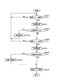
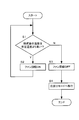
- FIG. 14 is a flowchart showing an operation in which the automatic bread maker 1 starts a manufacturing course.
- the start operation of the manufacturing process is specifically that the user selects and determines a desired manufacturing process (manufacturing course) via the input unit 21, and the control device 130 performs the manufacturing process (manufacturing). This is the operation until the course) starts.
- control device 130 allows the user to operate the input unit 21 (for example, a selection key) to select a desired manufacturing course (for example, the output unit displays an image indicating the desired manufacturing course). (STEP 1, NO).
- the controller 130 confirms that the manufacturing course has been selected by the user (STEP 1, YES)
- the controller 130 confirms the temperature of the firing chamber 30 detected by the temperature sensor 15 (STEP 2).
- the control apparatus 130 confirms whether the temperature of the confirmed baking chamber 30 is more than the upper limit temperature set with respect to the manufacturing course which the user selected (STEP3).
- the upper limit temperature is a limit temperature set for manufacturing a food with a high degree of perfection, and is a preferable temperature when the temperature of the baking chamber 30 is lower than the start of the manufacturing course.
- This upper limit temperature is set for each manufacturing course. Specifically, for example, in the above-described various bread-making courses (see FIG. 13), the fungi necessary for performing the fermentation process at an appropriate temperature (30 ° C. in the above-described example) or performing the fermentation process (the above-described example) Then, for example, 40 ° C. is set as the upper limit temperature in order to suppress weakening and death of dry yeast.
- the fermentation process is not performed (for example, the dough is inflated with baking powder or the like).
- the upper limit temperature is not set, such as a “making jam course” which is a manufacturing course (manufacturing process) for manufacturing jam.
- the controller 130 controls the output unit 22 to notify that the firing chamber 30 is at a high temperature (STEP 4). .
- the control device 130 controls the output unit 22 to display a “high temperature in the cabinet” message or to output an error sound. Then, the control device 130 prohibits the determination of the manufacturing course selected by the user, and returns to STEP 1 to cause the user to select the manufacturing course again.
- control device 130 individually notifies the user of the manufacturing process that cannot be performed because the temperature of the baking chamber 30 is equal to or higher than the upper limit temperature by controlling the output unit 22. Therefore, the convenience of the automatic bread maker 1 can be improved.
- the control device 130 allows the execution of the manufacturing course selected by the user. Specifically, when the control device 130 confirms that the user has determined the manufacturing course by operating the input unit 21 (for example, the determination key) (STEP 5, YES), the next STEP is executed to execute the manufacturing course. Proceed to When the control unit 130 confirms that the user does not determine the manufacturing course by operating the input unit 21 (for example, the determination key) (STEP 5, NO), the control device 130 returns to STEP 1 and causes the user to select the manufacturing course again. .
- the control device 130 allows the execution of the manufacturing process that does not cause a problem that the temperature of the baking chamber 30 is high as much as possible. Specifically, for example, in a manufacturing process (such as a cake making course or a jam making course) in which the control device 130 does not need to lower the temperature of the baking chamber 30 in order not to perform fermentation, the temperature of the baking chamber 30 is high. Even execution is allowed. Therefore, the convenience of the automatic bread maker 1 can be improved.
- the control device 130 confirms the temperature of the baking chamber 30 detected by the temperature sensor 15 (STEP 6). And the control apparatus 130 confirms whether the temperature of the confirmed baking chamber 30 is less than the minimum temperature set with respect to the manufacturing course which the user selected (STEP7).
- the lower limit temperature is a limit temperature set in order to produce food with a high degree of perfection, and is a preferable temperature when the temperature of the baking chamber 30 is higher at the start of the manufacturing course.
- This lower limit temperature is set for each manufacturing course. Specifically, for example, in the cake making course (details will be described later), in order to perform the step of kneading (kneading) the fats and fats such as butter and the flour such as flour while first holding the baking chamber 30 at 45 ° C. 20 ° C. is set as the lower limit temperature. There may be a manufacturing course in which the lower limit temperature is not set.
- the controller 130 confirms that the confirmed temperature of the firing chamber 30 is lower than the lower limit temperature (STEP 7, YES)
- the manufacturing process is started after executing a predetermined heating process for driving the sheathed heater 31 (STEP 8).
- the start operation of the manufacturing process is completed.
- the control device 130 starts the manufacturing course as it is (STEP 9), and ends the start operation of the manufacturing process. .
- FIG. 15 is a schematic diagram showing the flow of a cake making course.
- the cake making course shown in FIG. 15 is executed in a state where a predetermined amount of raw materials (for example, flour (weak flour), eggs, unsalted butter, sugar, baking powder, liquor, etc.) are put in the second bread container 110. Is done.
- raw materials for example, flour (weak flour), eggs, unsalted butter, sugar, baking powder, liquor, etc.
- FIG. 15A shows a case where the temperature of the baking chamber 30 when starting the cake making course is 20 ° C. or more which is the lower limit temperature.
- the controller 130 first performs the kneading process for 10 minutes.
- the control device 130 controls the kneading motor 50 to rotate the second blade rotating shaft 111 in the forward direction.
- the control apparatus 130 maintains the temperature of the baking chamber 30 at 45 degreeC by driving the sheathed heater 31, confirming the temperature which the temperature sensor 15 detects.
- the control device 130 performs the firing step for 60 minutes. In this process, the control device 130 maintains the temperature of the baking chamber 30 at 110 ° C. by driving the sheathed heater 31 while checking the temperature detected by the temperature sensor 15.
- FIG. 15B shows a case where the temperature of the baking chamber 30 when starting the cake making course is less than 20 ° C. which is the lower limit temperature.
- the control device 130 performs the heating process (negotiation process) for 20 minutes before performing the cake making course (see FIG. 15A).
- the controller 130 maintains the temperature of the baking chamber 30 at 40 ° C. by driving the sheathed heater 31 while checking the temperature detected by the temperature sensor 15.
- the control device 130 sets the temperature of the baking chamber 30 to the operating temperature of the process (for example, 45 ° C. in the kneading (kneading) process of the cake making process described above). ) (For example, 40 ° C.). Therefore, in this process, the temperature of the baking chamber 30 can be quickly brought to the operating temperature.
- the control device 130 sets the temperature of the baking chamber 30 to the operating temperature of the process (for example, 45 ° C. in the kneading process of the cake making process described above). And prevent the operating temperature from being exceeded (for example, 40 ° C.). Therefore, it becomes possible to hold the firing chamber 30 at an appropriate temperature before the process.
- the control device 130 increases the temperature of the firing chamber 30 as necessary before executing the manufacturing process in which the lower limit temperature is set.
- the control device 130 does not execute the manufacturing process if the temperature of the baking chamber 30 is equal to or higher than the upper limit temperature. Therefore, it becomes possible to start the manufacturing process at a temperature suitable for execution. Therefore, it is possible to produce a food with a high degree of perfection (for example, a cake or the like).
- the automatic bread maker of the second embodiment is generally the same as the configuration of the automatic bread maker 1 of the first embodiment. For this reason, about the structure of the automatic bread maker of 2nd Embodiment, it squeezes and demonstrates the characteristic part different from 1st Embodiment. In addition, the same code
- the automatic bread maker of the second embodiment is different from the automatic bread maker of the first embodiment in that it includes a cooling mechanism using a fan, as shown in FIGS.
- FIG. 16 is a schematic cross-sectional view of the automatic bread maker according to the second embodiment.
- FIG. 16 is a diagram illustrating a state in which no bread container is accommodated in the baking chamber 30.
- the left side of the figure corresponds to the front side of the automatic bread maker, and the right side of the figure corresponds to the back side of the automatic bread maker.
- FIG. 17 is a block diagram showing the configuration of the automatic bread maker of the second embodiment.
- a plurality of first vent holes 32 are formed in the front side wall 30bf of the firing chamber 30 so as to be arranged in the depth direction.
- the first vent holes 32 are obtained by performing a process of projecting a part of the front side wall 30bf made of sheet metal in a direction toward the outside of the firing chamber 30 (left side direction in FIG. 16).
- the first vent hole 32 is formed so that the upper side of the portion protruding to the outside of the firing chamber 30 is opened, and into the firing chamber 30 obliquely downward from this opening (right obliquely downward in FIG. 16). It is the structure in which the passage of the air connected to is formed.
- a plurality of second vent holes 33 are formed in the depth direction on the rear side wall 30bb facing the front side wall 30bf.
- the number is the same as the number of the first ventilation holes 32, but the number is not necessarily the same as the number of the first ventilation holes 32.
- the second vent hole 33 is obtained by performing a process of projecting a part of the rear side wall 30bb made of sheet metal in a direction toward the outside of the firing chamber 30 (right side in FIG. 16).
- the second vent hole 33 is formed so that the upper side of the portion protruding to the outside of the firing chamber 30 is opened, and into the firing chamber 30 obliquely downward (left obliquely downward in FIG. 16) from this opening. It is the structure in which the passage of the air connected to is formed.
- the square-shaped duct 18 is arranged on the rear side so as to cover the second vent hole 33 formed in the rear side wall 30 bb of the firing chamber 30 from the outside of the firing chamber 30. It is attached to the side wall 30bb.
- the other end portion of the duct 18 is attached to the main body 10 so as to cover a plurality of slit portions 10 c provided on the back surface of the main body 10 from the inside of the main body 10.
- the duct 18 provided in this way is configured to communicate the firing chamber 30 and the outside of the main body 10 via the second ventilation hole 33 and the slit portion 10c.
- the fan 17 which is an axial fan is attached to the inside of the duct 18 and near the slit portion 10c.
- air is taken into the firing chamber 30 from the outside of the firing chamber 30 through the first vent 32 as indicated by broken line arrows in FIG. 16, and the second vent 33 and Air in the firing chamber 30 is discharged to the outside of the main body 10 through the duct 18. That is, by driving the fan 17, air (air cooler than the inside of the baking chamber 30) is taken into the baking chamber 30 from the outside, and air (warmed air) in the baking chamber 30 is discharged to the outside of the main body 10. The air flow is made, and the inside of the baking chamber 30 is cooled.
- first vent holes 32 and the second vent holes 33 are not limited to the configuration of the present embodiment, so that the bread container accommodated in the baking chamber 30 can be efficiently cooled. It may be changed as appropriate.
- the positions where the first vent hole 32 and the second vent hole 33 are formed are the side walls 30bf and 30bb facing each other.
- an air inlet (first air hole 32) and an air outlet (second air hole 33) are provided so as to sandwich the bread container accommodated in the baking chamber 30, and the air generated by the fan 17 is provided.
- the bread container can be efficiently cooled by the flow.
- the first vent hole 32 and the second vent hole 33 are processed to project part of the side walls 30bf and 30bb in the direction toward the outside of the baking chamber 30.
- the first vent hole 32 and the second vent hole 33 may be obtained by performing a process of projecting a part of the side walls 30bf and 30bb in the direction toward the firing chamber 30.
- the configuration as in the present embodiment is preferable because a structure in which foreign matter hardly enters the main body 10 or the duct 18 from the firing chamber 30 is preferable.
- the configuration as in the present embodiment is preferable because there is no protrusion in the baking chamber 30, and it is difficult for a catch or the like to occur in the baking chamber 30.
- the 1st ventilation hole 32 and the 2nd ventilation hole 33 are good also as a hole opened by the drill etc. in the side walls 30bf and 30bb.
- the fan 17 is provided in the duct 18, but it goes without saying that a cooling fan may be attached to the outside of one end of the duct 18.
- the driving of the fan 17 is controlled by a fan motor drive circuit 136 that executes a control operation based on a command from the control device 130.
- the drive of the fan 17 is controlled as shown in FIG.
- the control device 130 instructs the fan motor drive circuit 136 not to drive the fan 17.
- the control device 130 instructs the fan motor drive circuit 136 to drive the fan 17. For this reason, it can suppress that the temperature of the bread raw material of a bread container rises too much.
- the controller 130 commands the fan motor drive circuit 136 to drive the fan 17 even during the pause process.
- the control device 130 commands the fan motor drive circuit 136 to drive the fan 17.
- the temperature in the baking chamber 30 rises due to the rotation of the kneading motor 50 in the kneading step, and the temperature of the bread raw material is desirable (a desirable temperature for actively working the yeast, for example, around 30 degrees). It is possible to suppress deviation.
- the controller 130 instructs the fan motor drive circuit 136 not to drive the fan 17 between the fermentation process and the baking process performed thereafter.
- the automatic bread maker of the second embodiment is characterized in that the control device 130 drives the fan 17 after the baking process is finished (after the bread making course is finished).
- FIG. 19 is a flowchart relating to the cooling control after the bread manufacturing process performed by the automatic bread maker of the second embodiment. When the flowchart shown in FIG. 19 is started, the control device 130 shifts to a mode in which the bread making course start operation by the operation unit 20 is not accepted.
- step S1 the control device 130 checks the temperature of the baking chamber 30 detected by the temperature sensor 15, and determines whether or not the temperature of the baking chamber 30 is higher than a predetermined temperature.
- the predetermined temperature is the temperature of the baking chamber 30 at which the bread-making course can be started, and can be 40 ° C., for example.
- Step S1 If the result of the determination is that the temperature of the firing chamber 30 is higher than the predetermined temperature (Y in Step S1), the process proceeds to Step S2, and the control device 130 instructs the fan motor drive circuit 136 to drive the fan 17. Start. And it returns to step S1 and it determines about the temperature of the baking chamber 30 again. While the temperature of the baking chamber 30 detected by the temperature sensor 15 is higher than the predetermined temperature, the driving of the fan 17 is continued.
- step S1 When it is determined in step S1 that the temperature of the baking chamber 30 has become equal to or lower than the predetermined temperature due to cooling by the fan 17 (N in step S1), the process proceeds to step S3, and the control device 130 does not drive the fan 17.
- the instruction to the fan motor drive circuit 136 is started.
- step S ⁇ b> 4 the control device 130 shifts to a mode for accepting a bread-making course start operation by the operation unit 20. Thereafter, when an operation for starting a bread making course is performed by the operation unit 20, the control device 130 starts the bread making course.
- the fan 17 is driven until the temperature of the baking chamber 30 becomes equal to or lower than a predetermined temperature at which the bread making course can be started. Transition to the mode to accept. Therefore, it is possible to shorten the cooling time until the temperature is lower than the predetermined temperature as compared with natural cooling, and as a result, the next bread making course can be started in a short time.
- the control device 130 may instruct the fan motor drive circuit 136 to drive the cooling fan 17 for a predetermined time. Good. This fixed time may be set by experimentally obtaining a cooling time such that the temperature of the baking chamber 30 is equal to or lower than a predetermined temperature.
- the driving rotational speed of the fan 17 may be increased as compared with the cooling control during the bread making course. Thereby, the next bread-making course can be started in a shorter time.
- the automatic bread maker of the third embodiment is generally the same as the configuration of the automatic bread maker 1 of the first embodiment. For this reason, about the structure of the automatic bread maker of 3rd Embodiment, it squeezes and demonstrates the characteristic part different from 1st Embodiment. In addition, the same code
- the automatic bread maker according to the third embodiment is characterized in that it has a plurality of bread making courses corresponding to environmental changes that are automatically used depending on the detected temperature, and can stably produce good bread.
- the automatic bread maker of 3rd Embodiment is an automatic bread maker provided with the bread making course corresponding to an environmental change automatically used properly by detection temperature, Comprising: A 1st temperature detection part and said 1st A second temperature detection unit disposed at a different position from the temperature detection unit, a first temperature detected by the first temperature detection unit, and a second temperature detected by the second temperature detection unit And a selection unit that selects one course to be executed from among the plurality of bread making courses corresponding to environmental changes.
- the automatic bread maker of the third embodiment selects one course from a plurality of bread making courses (bread making courses) corresponding to environmental changes using two temperature detection units arranged at different positions. It is the composition to do. For this reason, it is possible to select an appropriate course for the bread making course corresponding to the environmental change at the time when the bread manufacturing operation is started. In particular, even when the automatic bread maker is continuously operated, there is an advantage in that it is possible to select an appropriate course for a bread making course corresponding to environmental changes.
- the automatic bread maker of the third embodiment includes a baking chamber for storing a bread container into which bread ingredients are charged, and the first temperature detection unit is provided so as to detect the temperature of the baking chamber, It is preferable that the second temperature detector is provided so as to detect the ambient temperature of the automatic bread maker.
- an automatic bread maker is provided with a temperature detection unit that detects the temperature of the baking chamber. For this reason, this structure is realizable if one temperature detection part which detects the ambient temperature of an automatic bread maker is added.
- a course to be executed by the user can be selected from a plurality of bread making courses that are selectively used depending on the raw materials used.
- the plurality of bread-making courses corresponding to environmental changes are prepared, and the selection unit selects one bread-making course from the plurality of bread-making courses that can be selected by the user.
- one course to be executed is selected from the plurality of bread making courses corresponding to the environmental change. It is preferable.
- FIG. 20 is a block diagram showing the configuration of the automatic bread maker of the third embodiment.
- the automatic bread maker of the third embodiment in addition to the first temperature sensor 15 which is a temperature sensor for detecting the temperature of the baking chamber 30, the ambient temperature of the automatic bread maker (the automatic bread maker is placed).
- a second temperature sensor 19 that is a temperature sensor for detecting a room temperature
- the second temperature sensor 19 is attached to, for example, the outer shell (for example, the inner side of the outer shell) of the main body 10.
- the second temperature sensor 19 is preferably disposed at a position that is not easily affected by the heat generated in the baking chamber 30.
- the kneading motor driving unit 131 controls the driving of the kneading motor 50 under a command from the control device 130. Further, the pulverization motor driving unit 132 controls the driving of the pulverization motor 60 under a command from the control device 130.
- the heater driving unit 133 controls the heating operation of the sheathed heater 31 under a command from the control device 130.
- the clutch switching unit 134 switches the power transmission state of the clutch 56 (see FIG. 2) included in the first power transmission unit PT1 under a command from the control device 130 (see FIG. 3A and FIG. 3). 3B) is controlled.
- the automatic charging drive unit 135 controls the driving of an automatic charging solenoid 16 (see FIG. 12) that is driven when a part of bread ingredients are automatically charged during the bread manufacturing process.
- the cooling fan drive unit 136 controls the driving of the cooling fan 17 (see FIG. 16) under a command from the control device 130.
- the control device 130 performs a predetermined operation (described later) based on an input signal from the operation unit 20, and then reads a program related to a bread manufacturing course (breadmaking course) stored in a ROM or the like.
- the control device 130 controls the rotation of the kneading blade 101 by the kneading motor 50 via the kneading motor driving unit 131, controls the rotation of the grinding blade 92 by the grinding motor 60 via the grinding motor driving unit 132, and controls the heater driving unit 133. While controlling the heating operation by the sheathed heater 31 and the drive control of the cooling fan 17 via the cooling fan drive unit 136, the automatic bread maker performs the bread manufacturing process.
- the bread making course for rice grains shown in FIG. 13 (a) can be performed using the first bread container 80.
- rice grains such as white rice, brown rice, and milled rice.
- the time of each process shown to Fig.13 (a) is determined by experiment etc. for every kind of rice grain.
- the auxiliary materials (gluten, wheat flour, super fresh flour, etc.) used to improve the bulge of bread have different properties. For this reason, it is preferable that the time of each process shown to Fig.13 (a) is determined by experiment etc. for every kind of auxiliary material to be used.
- the bread making course for rice grains in the automatic bread maker of the third embodiment precisely, it is classified according to the type of rice grains, and further classified into a plurality according to the difference in the auxiliary materials using each of them.
- a plurality of bread-making courses are determined (see FIG. 21; there are 7 courses in FIG. 21). The user can select a course according to the purpose from the plurality of bread making courses.
- the plurality of bread-making courses may be collectively expressed as a rice grain bread-making course.
- each of the plurality of bread-making courses is adapted to three environmental changes such as a standard course, a summer course, and a winter course so that it can cope with changes in the environment where the automatic bread maker is placed, such as seasonal fluctuations.
- Courses (sometimes simply referred to as environmental change courses) are provided (see FIG. 21). This course corresponding to environmental change is not selected by the user, but is automatically selected by the control device 130 before starting the bread manufacturing operation. Details of this course for dealing with environmental changes will be described later.
- the bread baking course for flour shown in FIG. 13B can be performed using the second bread container 110.
- two environmental change courses such as a standard course and a summer course are provided so as to cope with changes in the environment where the automatic bread maker is placed, such as seasonal fluctuations (see FIG. 22). .
- This course corresponding to environmental change is not selected by the user, but is automatically selected by the control device 130 before starting the bread manufacturing operation.
- a winter course may be provided in the same manner as the bread-making course for rice grains. The details of the course for dealing with environmental changes provided in the automatic bread maker of the third embodiment will be described below.
- the automatic bread maker of the third embodiment is provided with an environment change course for each of the bread making courses selected by the user in order to cope with the change in the environment where the bread maker is placed. It has a configuration.
- the automatic bread maker of the third embodiment takes into account the temperatures detected by the first temperature sensor 15 and the second temperature sensor 19 (see FIG. 20) before the bread manufacturing operation is started. Thus, a course appropriately corresponding to the environment in which it is placed is selected, and bread manufacturing operations are performed according to the selected course.
- FIG. 23 is a flowchart showing a seasonal course automatic selection flow in the automatic bread maker of the third embodiment.
- a user selects a bread making course (rice grain bread making course or flour bread making course) to be executed by the automatic bread maker of the third embodiment, and issues a command to execute the bread manufacturing process. Later, the automatic selection of the seasonal course is started. Specifically, when the user selects a bread-making course and presses the start key, the automatic operation for selecting the seasonal course is started.
- the control device 130 determines whether or not the temperature of the baking chamber 30 is A ° C. or less based on the information obtained from the first temperature sensor 15 (step S1).
- the control device 130 notifies an error (for example, notification sound and / or error display on the liquid crystal panel) and stops the bread making operation.
- the user waits until the baking chamber 30 becomes A ° C. or lower, selects a desired breadmaking course using the operation unit 20 again, and presses the start key. Note that the bread making operation may be automatically resumed when the baking chamber 30 becomes A ° C. or lower by interrupting the bread making operation instead of stopping.
- a ° C may be 40 ° C, for example. If A ° C is set too high, bad bread will be obtained with a fairly high probability, for example, because the yeast does not work properly. On the other hand, when A ° C is too low, it is considered that the second and subsequent bread production cannot be easily started when the automatic bread maker is continuously operated, and the user feels inconvenient. A ° C may be determined in consideration of such points.
- step S1 the control device 130 uses the information obtained from the first temperature sensor 15 and the second temperature sensor 19 to determine the temperature of the baking chamber 30. And whether or not the difference from the ambient temperature of the automatic bread maker is B ° C. or less (step S2).
- This temperature range of B ° C. or lower is determined based on the quality of the bread (taste, baked color, etc.) when the bread is manufactured with the same control operation, and the temperature of the baking chamber 30 is the ambient temperature of the automatic bread maker (ie, automatic This is a range that can be regarded as equivalent to the temperature of the environment in which the bread maker is placed, and is determined by experiment.
- This B ° C. may be about 3 to 5 ° C., for example.
- the control apparatus 130 determines the judgment standard of a seasonal course (environment change corresponding course) to the ambient temperature of an automatic bread maker (step S3).
- the temperature of the baking chamber 30 may be used as a criterion for the seasonal course.
- the controller 130 selects the summer course when the ambient temperature of the automatic bread maker is higher than 25 ° C., and the standard course when the temperature is 20 ° C. or higher and 25 ° C. or lower. If the temperature is lower than 20 ° C., the winter course is automatically selected.
- the control device 130 automatically selects the summer course when the ambient temperature of the automatic bread maker is higher than 30 ° C and the standard course when the ambient temperature is 30 ° C or lower. select.
- the seasonal course is automatically selected, the bread manufacturing operation is started (step S4).
- the above-mentioned temperature range used when selecting a seasonal course is an example, and may be changed as a matter of course.
- step S5 determines the time until the kneading process in the bread making course selected by the user. Is equal to or longer than C minutes (step S5).
- the time until the kneading step is determined based on the operation start time for producing bread.
- the time until the kneading process may not be accurately calculated. In such a case, the determination in step S5 may be performed using a seasonal course having the shortest time to the kneading process.
- Step S2 is determined as Yes.
- an immersion process (the motor and heater are not driven in this process) is performed first, which can be regarded as a mere standing period and has a relatively long process time.
- this dipping process it is assumed that the temperature in the firing chamber 30 decreases every moment. For this reason, when the bread-making course for rice grains is selected, if the seasonal course is determined based on the temperature of the baking chamber 30, there is a high possibility that bad bread will be produced.
- the portion C in step S5 is, for example, the time from the start of the bread making course for rice grains (the start of bread making operation) to the start of the kneading process (the shortest because there are multiple course settings in detail) For example, about 90 minutes or the like.
- the confirmation of step S5 may simply be "whether the course selected by the user is a rice grain bread maker". In this case, it can be said that the time taken until the kneading process is started is considered.
- the automatic bread maker of the third embodiment is provided such that timer reservation is possible using an input means (input key) provided in the operation unit 20.
- the automatic bread maker is configured so that the seasonal course is selected when the timer reservation function is used when the timer reservation function is used (points to the time when the timer function starts operating).
- step S5 it is preferable to adopt the configuration of this embodiment in which the configuration of “confirming the time until the kneading process” is employed.
- the time until the kneading process is determined based on the time when the timer reservation is made.
- step S5 The confirmation in step S5 is provided in consideration of the above points. Therefore, in the case of Yes in step S5, the control device 130 determines the determination criterion of the seasonal course (environment change course) as the ambient temperature of the automatic bread maker (determining in step S3). Further, in the case of No in step S5, the control device 130 determines the determination criterion of the seasonal course as the temperature of the baking chamber 30 (step S6).
- step S4 The operation after the determination criteria for the seasonal course are determined is the same as step S4 described above. However, the judgment criteria for the seasonal course are different between the case of passing through step S3 and the case of passing through step S6. In this respect, it should be noted that a difference from the description of the previous step S4 occurs.
- the control device 130 is an example of a selection unit that selects one course to be executed from among a plurality of bread making courses corresponding to environmental changes.
- the 1st temperature sensor 15 which detects the temperature of the baking chamber 30 is an example of the above-mentioned 1st temperature detection part, and the temperature of the baking chamber 30 is an example of the above-mentioned 1st temperature.
- the second temperature sensor 19 that detects the ambient temperature of the automatic bread maker is an example of the second temperature detection unit described above, and the ambient temperature of the automatic bread maker is an example of the second temperature described above. is there.
- the seasonal course (environmental change course) can be automatically selected with only one temperature sensor that can detect the temperature of the baking chamber 30.
- the automatic selection of the seasonal course may be inappropriate with this temperature sensor alone.
- the automatic bread maker of the third embodiment is configured to select a seasonal course in consideration of the temperatures obtained from the two temperature sensors 15 and 19, and even when the automatic bread maker is continuously operated, It is possible to appropriately select the seasonal course automatically before the bread making operation is started.
- 3rd Embodiment application of the structure of 3rd Embodiment is not restricted to the automatic bread maker which can perform the bread-making course for rice grains, and the bread-making course for wheat flour. That is, for example, the configuration of the third embodiment can be applied to an automatic bread maker that can execute a rice flour bread course in addition to a rice grain bread course and wheat flour bread course.
- the structure of 3rd Embodiment is applicable also to the automatic bread maker which can perform the bread-making course for rice grains, and the bread-making course for rice flour.
- it is applicable also to the conventional automatic bread maker (it has a bread-making course for wheat flour, and a bread-making course for rice flour) which cannot perform the bread-making course for rice grains.
- rice grains are exemplified as the grain grains, and the configuration and operation of the automatic bread maker have been described.
- the present invention is also applicable when grain grains other than rice grains such as wheat, barley, straw, buckwheat, buckwheat, corn, and soybean are used as starting materials.
- the automatic bread maker of the present invention is not necessarily limited to one that can execute all these steps.
- those that cannot execute at least one step except the dough manufacturing step can be included in the automatic bread maker of the present invention.
- the present invention is suitable for an automatic bread maker for home use.
Landscapes
- Engineering & Computer Science (AREA)
- Food Science & Technology (AREA)
- Baking, Grill, Roasting (AREA)
Abstract
自動製パン器は、焼成室30を加熱可能な加熱部31と、焼成室30の温度を検知する温度検知部15と、実行する製造コースに応じて加熱部31を制御する制御部130と、を備える。制御部130は、下限温度が設定されている製造工程を実行しようとする際に、温度検知部15が検知する温度が下限温度未満であるか否かを確認する。制御部130は、温度検知部15が検知する温度が下限温度未満であることを確認すると、製造コースを実行する前に加熱部31により焼成室30を加熱する工程を行う。これにより、製造コースを、実行に適した温度で開始する。
Description
本発明は、主として一般家庭で使用される自動製パン器に関する。
市販の家庭用自動製パン器は、パン原料を入れるパン容器をそのまま焼き型としてパンを製造する仕組みのものが一般的である(例えば、特許文献1参照)。このような自動製パン器では、まず、パン原料が入れられたパン容器が本体内の焼成室に入れられる。そして、パン容器内のパン原料がパン容器内に設けられる混練ブレードでパン生地に練り上げられる(練り工程)。その後、練り上げられたパン生地を発酵させる発酵工程が行われ、パン容器が焼き型として使用されてパンが焼き上げられる(焼成工程)。
自動製パン器が有する混練機構や加熱機構などの機構は、パンの製造のみならず、他の食品(例えば、ケーキや麺生地、ジャムなど)の製造にも利用可能である。そのため、自動製パン器の中には、パンを含む複数の食品の製造工程を実行可能なものがある。しかしながら、このような自動製パン器では、状況によって完成度の低い食品が製造されることがある。
そこで、本発明の目的は、完成度の高い食品を製造可能な自動製パン器を提供することである。
上記目的を達成するために本発明の自動製パン器は、原料が投入される容器が設置される焼成室と、前記焼成室を加熱可能な加熱部と、前記焼成室の温度を検知する温度検知部と、実行する製造コースに応じて前記加熱部を制御する制御部と、を備え、前記制御部が実行可能な少なくとも1つの製造コースの中には、下限温度が設定されるとともに、最初に行うべき工程に動作温度が設定されている第1の製造コースが含まれ、前記制御部は、前記第1の製造コースを実行しようとする際、前記温度検知部が検知する温度が、当該下限温度未満であることを確認すると、前記第1の製造コースを実行する前に、前記加熱部により前記焼成室を加熱する加熱工程を行い、その後、前記制御部は、前記温度検知部が検知する温度が当該動作温度と略等しくなるように、前記加熱部を制御して、前記第1の製造コースの最初に行うべき工程を行う構成となっている。
本構成によれば、制御部が、下限温度が設定された製造コースを実行する前に、必要に応じて焼成室の温度を上げる。そのため、当該製造コースを、実行に適した温度で開始することが可能になる。また、制御部が、製造コースの最初に行うべき工程を行う前に、焼成室の温度を当該工程の動作温度に近づける。そのため、当該工程において、焼成室の温度を迅速に動作温度にすることが可能になる。
上記構成の自動製パン器では、前記加熱工程において、前記制御部は、前記温度検知部が検知する温度が前記下限温度よりも高く前記動作温度以下の温度となるように前記加熱部を制御することとしてもよい。本構成によれば、制御部が、製造コースの最初に行うべき工程を行う前に、焼成室の温度を当該工程の動作温度に近づけ、かつ当該動作温度を超えることを防止する。そのため、当該工程の前に、焼成室を適切な温度で保持することが可能になる。
上記構成の自動製パン器において、前記制御部は、上限温度が設定されている製造コースを実行しようとする際に、前記温度検知部が検知する温度が当該上限温度以上であることを確認すると、当該製造コースを実行しないものであり、前記制御部が実行可能な製造コースの中には、設定される前記上限温度が異なる少なくとも2つの製造コースが含まれる構成としてもよい。本構成によれば、製造コース毎に異なった上限温度が設定され得る。そのため、制御部が、焼成室の温度が高いことが問題にならない製造コースについては、可能な限り実行を許容する。したがって、自動製パン器の利便性を向上させることが可能になる。また、制御部は、上限温度が設定された製造工程を実行しようとする際に、焼成室の温度が上限温度以上であれば、当該製造工程を実行しない。そのため、当該製造工程を、実行に適した温度で開始することが可能になる。
上記構成の自動製パン器において、発酵工程を含む製造コースと、発酵工程を含まない製造コースとで、設定される前記上限温度が異なるように設けられ、前記発酵工程を含まない製造コースに設定される前記上限温度は、前記発酵工程を含む製造コースに設定される前記上限温度よりも高い構成としてもよい。本構成によれば、制御部が、発酵を行わないために焼成室の温度を下げておく必要がない製造コースについては、焼成室の温度が高くても実行を許容する。そのため、自動製パン器の利便性を向上させることが可能になる。
上記構成の自動製パン器において、ユーザの指示を前記制御部に入力する入力部と、 前記制御部によって制御され、ユーザに対して報知を行う出力部と、をさらに備え、ユーザが、前記上限温度が設定されている製造コースを選択する指示を前記入力部に入力するとき、前記制御部が、前記温度検知部が検知する温度が当該上限温度以上であることを確認すると、前記出力部を制御して、前記焼成室が当該上限温度以上であることをユーザに対して報知することとしてもよい。本構成によれば、制御部が、焼成室の温度が上限温度以上であるため実行不可能な製造工程を、出力部を制御することで個別的にユーザに対して報知する。そのため、自動製パン器の利便性を向上させることが可能になる。
上記構成の自動製パン器において、前記制御部は、上限温度が設定されている製造コースを実行しようとする際に、前記温度検知部が検知する温度が当該上限温度以上であることを確認すると、当該製造コースを実行しないものであり、前記制御部が実行可能な製造コースの中には、前記第1の製造コースの他に第2の製造コースが含まれ、前記第1の製造コースに設定される前記上限温度と、前記第2の製造コースに設定される前記上限温度とは異なる温度である構成としてもよい。
上記構成の自動製パン器において、前記第1の製造コースは発酵を行う工程を含まないものであり、前記第2の製造コースは発酵を行う工程を含むものであり、前記第1の製造コースの前記上限温度は、前記第2の製造コースの前記上限温度よりも高い構成であるのが好ましい。
上記構成の自動製パン器において、前記第1の製造コースはケーキを製造するためのコースであり、前記第2の製造コースはパンを製造するためのコースである構成としてもよい。
本発明によると、製造工程(製造コース)を、実行に適した温度で開始することが可能になる。したがって、完成度の高い食品(例えば、ケーキ等)を製造することが可能になる。
以下、本発明の自動製パン器の実施形態について、図面を参照しながら詳細に説明する。なお、本明細書に登場する具体的な時間や温度等はあくまでも例示であり、それらは本発明の内容を限定するものではない。
1.第1実施形態
(自動製パン器の構成)
図1は、第1実施形態の自動製パン器の外観構成を示す概略斜視図である。図1に示すように、略直方体形状に設けられる自動製パン器1の本体10(その外殻は例えば金属や合成樹脂等によって形成される)の上面の一部には、操作部20が設けられている。この操作部20は、ユーザに操作されることでユーザの指示が入力される操作キー群を含む入力部21と、入力部21を介して入力されるユーザの指示によって設定された内容や、エラー等を表示する出力部22と、によって構成されている。
(自動製パン器の構成)
図1は、第1実施形態の自動製パン器の外観構成を示す概略斜視図である。図1に示すように、略直方体形状に設けられる自動製パン器1の本体10(その外殻は例えば金属や合成樹脂等によって形成される)の上面の一部には、操作部20が設けられている。この操作部20は、ユーザに操作されることでユーザの指示が入力される操作キー群を含む入力部21と、入力部21を介して入力されるユーザの指示によって設定された内容や、エラー等を表示する出力部22と、によって構成されている。
入力部21に含まれる操作キー群には、例えば、スタートキー、取り消しキー、タイマーキー、予約キー、ユーザが所望する製造コース(米粒を出発原料に用いてパンを製造する製造工程、小麦粉(または米粉)を出発原料に用いてパンを製造する製造工程、小麦粉(または米粉)を出発原料に用いてケーキを製造する製造工程等)を選択する選択キー等が含まれる。出力部22は、例えば、液晶表示パネルや発光素子、スピーカ等によって構成され、音や光(画像を含む)を出力することで、ユーザに報知を行う。なお、入力部21は、本発明の入力部の一例であり、出力部22は、本発明の出力部の一例である。
本体10内部には、詳細は後述する第1のパン容器80が収容される焼成室30が設けられている。この焼成室30は、例えば板金からなる底壁30a及び4つの側壁30b(後述の図4も参照)で構成されている。焼成室30は、平面形状略矩形の箱形状で、その上面は開口している。この焼成室30は、本体10上部に設けられる蓋40によって開閉可能となっている。蓋40は、図示しない蝶番軸で本体10の背面側に取り付けられており、その蝶番軸を支点として回動することで、焼成室30の開閉が可能になっている。なお、図1は、この蓋40が開かれた状態を示している。
この蓋40には、焼成室30内を覗けるように、例えば耐熱ガラスからなる覗き窓41が設けられている。また、蓋40には、パン原料収納容器42が取り付けられている。このパン原料収納容器42は、パンの製造工程の途中で一部のパン原料を自動投入することを可能にしている。パン原料収納容器42は、平面形状略長方形の箱形状の容器本体42aと、容器本体42aに対して回動可能に設けられて、容器本体42aの開口を開閉する容器蓋42bとを備えている。また、パン原料収納容器42は、容器蓋42bを外面(下面)側から支えて容器本体42aの開口が閉じられた状態を維持可能であると共に、外部からの力によって動かされて容器蓋42bとの係合が解除される可動フック42cも備えている。
操作部20下部側の本体10内には自動投入用ソレノイド16(後述の図12参照)が設けられており、この自動投入用ソレノイドが駆動すると、そのプランジャーが、蓋40に隣接する本体壁面10aに設けられる開口10bから突出するようになっている。そして、この突出したプランジャーによって可動する可動部材(図示せず)によって可動フック42cが動かされ、容器蓋42bと可動フック42cとの係合が外れて容器蓋42bが回動し、容器本体42aの開口が開かれた状態になる。なお、図1においては、容器本体42aの開口が開かれた状態が示されている。
容器本体42a及び容器蓋42bは、容器内に収納される粉体パン原料(例えばグルテンやドライイースト等)が容器内に残留し難いように、アルミニウム等の金属で設けられるのが好ましい。そして、それらの表面は、シリコン系やフッ素系等のコーティング層で覆われるのが好ましく、アルマイト層で覆われるように構成するとさらに好ましい。また、容器本体42a及び容器蓋42bは、凹凸がなるべく設けられず、滑らかに形成されるのが好ましい。なお、蓋40の内側(パン原料収納容器42が取り付けられる側)も同様に、基材をアルミニウムとして、表面をシリコン系やフッ素系等のコーティング層やアルマイト層で覆われるように構成するのが好ましい。
また、米粒等の穀物粒を粉砕する際に発生する蒸気等が容器本体42a内に入り込むと、パン原料が容器内面に付着し易くなって好ましくない。このために、容器内に前述の蒸気等が入り込まないように、容器本体42aの開口側縁には鍔部(フランジ部)が設けられて、この鍔部と容器蓋42bとの間にはパッキン(シール部材)42dが介在するようになっている。
図2は、第1実施形態の自動製パン器の本体内部の構成を説明するための模式図である。図2は、自動製パン器1を上側から見た場合を想定しており、図の下側が自動製パン器1の正面側、図の上側が背面側である。図2に示すように、自動製パン器1には、焼成室30の右横に練り工程で用いられる低速・高トルクタイプの混練モータ50が固定配置され、焼成室30の後ろ側に粉砕工程で用いられる高速回転タイプの粉砕モータ60が固定配置されている。混練モータ50及び粉砕モータ60はいずれも竪軸である。
混練モータ50の上面から突出する出力軸51には第1のプーリ52が固定される。この第1のプーリ52は、第1のベルト53によって、その径が第1のプーリ52よりも大きく形成されるとともに第1の回転軸54の上部側に固定される第2のプーリ55に連結されている。第1の回転軸54の下部側には、その回転中心が第1の回転軸54とほぼ同一となるように第2の回転軸57が設けられている(後述の図3A及び図3B参照)。なお、第1の回転軸54及び第2の回転軸57は、本体10内部に回転可能に支持されている。また、第1の回転軸54と第2の回転軸57との間には、動力伝達と動力遮断を行うクラッチ56が設けられている(後述の図3A及び図3B参照)。このクラッチ56の構成については後述する。
第2の回転軸57の下部側には第3のプーリ58が固定されている(後述の図3A及び図3B参照)。第3のプーリ58は、第2のベルト59によって、焼成室30の下部側に設けられるとともに原動軸11に固定される第1の原動軸用プーリ12(第3のプーリ58とほぼ同一の径を有する)に連結されている(後述の図3A及び図3B参照)。混練モータ50自身が低速・高トルクタイプであり、その上、第1のプーリ52の回転が第2のプーリ55によって減速回転される(例えば1/5の速度に減速される)。このため、クラッチ56が動力伝達を行う状態で混練モータ50が駆動されると、原動軸11は低速で回転する。
以下においては、第1のプーリ52、第1のベルト53、第1の回転軸54、第2のプーリ55、クラッチ56、第2の回転軸57、第3のプーリ58、第2のベルト59、及び第1の原動軸用プーリ12で構成される動力伝達部が、第1の動力伝達部PT1と表現されることがある。
粉砕モータ60の下面から突出する出力軸61には、第4のプーリ62が固定されている。この第4のプーリ62は、第3のベルト63によって、原動軸11に固定される第2の原動軸用プーリ13(第1の原動軸用プーリ12より下側で固定される;後述の図3A及び図3B参照)に連結されている。第2の原動軸用プーリ13は第4のプーリ62とほぼ同一の径を有する。粉砕モータ60には高速回転のものが選定され、第4のプーリ62の回転は第2の原動軸用プーリ13においてほぼ同一速度で維持される。このために、粉砕モータ60が駆動されると、原動軸11は高速回転(例えば7000~8000rpm)を行う。
以下においては、第4のプーリ62、第3のベルト63、及び第2の原動軸用プーリ13で構成される動力伝達部が、第2の動力伝達部PT2と表現されることがある。第2の動力伝達部PT2は、クラッチを有さない構成であり、粉砕モータ60の出力軸61と原動軸11とを常時動力伝達可能に連結する。
図3A及び図3Bは、第1実施形態の自動製パン器が備える第1の動力伝達部に含まれるクラッチについて説明するための図である。図3A及び図3Bは、図2の矢印X方向に沿って見た場合を想定した図である。なお図3Aはクラッチ56が動力遮断を行う状態を示し、図3Bはクラッチ56が動力伝達を行う状態を示す。
図3A及び図3Bに示すように、クラッチ56は、第1のクラッチ部材561と第2のクラッチ部材562とを有する。そして、第1のクラッチ部材561に設けられる爪561aと、第2のクラッチ部材562に設けられる爪562aとが噛み合う場合(図3Bの状態)に、クラッチ56は動力伝達を行う。また、2つの爪561a、562aが噛み合わない場合(図3Aの状態)に、クラッチ56は動力遮断を行う。すなわち、クラッチ56は噛み合いクラッチとなっている。
なお、本実施形態では、2つのクラッチ部材561、562のそれぞれには、周方向(第1のクラッチ部材561を下から平面視した場合、或いは、第2のクラッチ部材562を上から平面視した場合を想定)にほぼ等間隔に並ぶ6つの爪561a、562aが設けられているが、この爪の数は適宜変更してもよい。また、爪561a、562aの形状は、好ましい形状を適宜選択すればよい。
第1のクラッチ部材561は、抜け止め対策を施された上で、第1の回転軸54に、その軸方向(図3A及び図3Bにおいて上下方向)に摺動可能、且つ、相対回転不能に取り付けられている。第1の回転軸54の第1のクラッチ部材561より上部側には、バネ71が遊嵌されている。このバネ71は、第1の回転軸54に設けられるストッパ部54aと第1のクラッチ部材561とに挟まれるように配置されており、第1のクラッチ部材561を下側に向けて付勢している。一方、第2のクラッチ部材562は、第2の回転軸57の上端に固定されている。
クラッチ56における、動力伝達状態と動力遮断状態との切り替えは、下位置と上位置とに選択配置可能なアーム部72を用いて行われる。アーム部72は、その一部が第1のクラッチ部材561の下側に配置され、第1のクラッチ部材561の外周部と当接可能となっている。
アーム部72が下位置(図3Bの状態)から上位置(図3Aの状態)に移動すると、第1のクラッチ部材561はバネ71の付勢力に抗して上方向に移動する。アーム部72が上位置にある場合には、第1のクラッチ部材561と第2のクラッチ部材562とは噛み合わない。すなわち、アーム部72が上位置にある場合には、クラッチ56は動力遮断を行う。
一方、アーム部72が上位置から下位置に移動すると、第1のクラッチ部材561はバネ71の付勢力によって押される形で下方向に移動する。アーム部72が下位置にある場合には、第1のクラッチ部材561と第2のクラッチ部材562とは噛み合う。すなわち、アーム部72が下位置にある場合には、クラッチ56は動力伝達を行う。
粉砕モータ60を駆動する際に、クラッチ56が動力伝達を行う状態(図3Bの状態)であると、原動軸11を高速回転させる回転動力が混練モータ50の出力軸51に伝達される(図2参照)。この場合、粉砕モータ60が例えば8000rpmで回転されるとすると、第1のプーリ52と第2のプーリ55との半径比(例えば1:5)によって、混練モータ50の出力軸51を40000rpmで回転させる力が必要になる。その結果、粉砕モータ60に非常に大きな負荷が加わるために、粉砕モータ60が破損する可能性がある。このため、粉砕モータ60を駆動する際には、原動軸11を高速回転させる回転動力が混練モータ50の出力軸51に伝達されないようにする必要がある。そこで、自動製パン器1は、上述のように、動力伝達と動力遮断を行うクラッチ56を第1の動力伝達部PT1に含む構成となっている。
なお、上述のように自動製パン器1においては、第2の動力伝達部PT2にはクラッチが設けられない構成としているが、これは次の理由による。すなわち、混練モータ50を駆動しても原動軸11は低速回転(例えば180rpm等)されるのみである。このため、原動軸11を回転させる回転動力が粉砕モータ60の出力軸に伝達されるようになっていても、混練モータ50に大きな負荷が加わることはない。そして、このように第2の動力伝達部PT2にクラッチが設けられない構成を敢えて採用することで、自動製パン器1の製造コストが抑制される。ただし、第2の動力伝達部PT2にクラッチが設けられる構成を採用しても、勿論構わない。
(第1のパン容器)
図4は、第1実施形態の自動製パン器における、第1のパン容器が収容された焼成室及びその周辺の構成を模式的に示す図である。図4は、自動製パン器1を正面側から見た場合の構成を想定しており、焼成室30及び第1のパン容器80の構成は概ね断面図で示されている。なお、パン原料が投入されるとともにパン焼き型として使用される第1のパン容器80は、焼成室30に対して出し入れ自在となっている。
図4は、第1実施形態の自動製パン器における、第1のパン容器が収容された焼成室及びその周辺の構成を模式的に示す図である。図4は、自動製パン器1を正面側から見た場合の構成を想定しており、焼成室30及び第1のパン容器80の構成は概ね断面図で示されている。なお、パン原料が投入されるとともにパン焼き型として使用される第1のパン容器80は、焼成室30に対して出し入れ自在となっている。
図4に示すように、焼成室30の内部には、シーズヒータ31が焼成室30に収容された第1のパン容器80を包囲するように配置されている。このシーズヒータ31を用いることにより、第1のパン容器80内のパン原料(この表現にはパン生地を含む場合がある)の加熱が可能になる。なお、シーズヒータ31は、本発明の加熱部の一例である。
また、焼成室30の底壁30aの略中心にあたる箇所には、第1のパン容器80を支持するパン容器支持部14(例えばアルミニウム合金のダイキャスト成型品からなる)が固定されている。このパン容器支持部14は、焼成室30の底壁30aから窪むように形成され、その窪みの形状は上から見た場合に略円形となっている。このパン容器支持部14の中心には、上述の原動軸11が底壁30aに対して略垂直となるように支持されている。
第1のパン容器80は例えばアルミニウム合金のダイキャスト成型品(その他、板金等で構成しても構わない)であり、バケツのような形状をしており、開口部側縁に設けられる鍔部80aに手提げ用のハンドル(図示せず)が取り付けられている。第1のパン容器80の水平断面は四隅を丸めた矩形である。また、第1のパン容器80の底部には、詳細は後述するブレードユニット90の一部を収容する平面視略円形状の凹部81が形成されている。
第1のパン容器80の底部中心には、垂直方向に延びるブレード回転軸82が、シール対策を施された状態で回転可能に支持されている。このブレード回転軸82の下端(第1のパン容器80の底部から外部側に突き出ている)には、容器側カップリング部材82aが固定されている。また、第1のパン容器80の底部外面側には筒状の台座83が設けられており、第1のパン容器80は、この台座83がパン容器支持部14に受け入れられた状態で、焼成室30内に収容されるようになっている。なお、台座83は、第1のパン容器80とは別に形成してもよいし、第1のパン容器80と一体的に形成してもよい。
第1のパン容器80の台座83がパン容器支持部14に受け入れられた状態で焼成室30内に収容されると、ブレード回転軸82の下端に設けられる前述の容器側カップリング部材82aと、原動軸11の上端に固定される原動軸側カップリング部材11aとの連結(カップリング)が得られるようになる。そして、これにより、ブレード回転軸82は原動軸11から回転動力を伝えられるようになる。
ブレード回転軸82の第1のパン容器80内部に突出する部分には、その上からブレードユニット90が着脱可能に取り付けられるようになっている。このブレードユニット90の構成について、図5、図6、図7A、図7B、図8A、図8B、図9A及び図9Bを参照しながら説明する。
なお、図5は、第1実施形態の自動製パン器が備えるブレードユニットの構成を示す概略斜視図である。図6は、第1実施形態の自動製パン器が備えるブレードユニットの構成を示す概略分解斜視図である。図7A及び図7Bは、第1実施形態の自動製パン器が備えるブレードユニットの構成を示す図で、図7Aは概略側面図、図7Bは図7AのA-A位置における断面図である。図8A及び図8Bは、第1実施形態の自動製パン器が備えるブレードユニットを下から見た場合の概略平面図で、図8Aは混練ブレードが折り畳み姿勢にある場合の図、図8Bは混練ブレードが開き姿勢にある場合の図である。図8A及び図8Bにおいては、後述のガードが取り外された状態を示している。図9A及び図9Bは、第1実施形態の自動製パン器が備える第1のパン容器を上から見た場合の図である。図9Aは混練ブレードが折り畳み姿勢にある場合の図、図9Bは混練ブレードが開き姿勢にある場合の図である。
ブレードユニット90は、大きくは、ユニット用シャフト91と、ユニット用シャフト91に相対回転不能に取り付けられる粉砕ブレード92と、ユニット用シャフト91に相対回転可能且つ粉砕ブレード92を覆うように取り付けられる平面視略円形のドーム状カバー93と、ドーム状カバー93に相対回転可能に取り付けられる混練ブレード101と、を備える構成となっている(例えば、図5、図6、図7A及び図7B参照)。ブレードユニット90がブレード回転軸82に取り付けられた状態において、粉砕ブレード92は、第1のパン容器80の凹部81底面より少し上の箇所に位置する。また、粉砕ブレード92及びドーム状カバー93のほぼ全体は凹部81に収容される。
ユニット用シャフト91は、例えばステンレス鋼板等の金属によって形成される略円柱状の部材であり、一方端(図6及び図7Bの下端)に開口が設けられ、その内部は中空となっている。すなわち、ユニット用シャフト91には、挿入孔91cが形成されている(図7B参照)。また、ユニット用シャフト91の側壁の下部側(開口側)には、ユニット用シャフト91の回転中心を挟んで対称配置される一対の切り欠き91aが形成されている(例えば図6参照。ただし図6では一方のみが示されている)。ユニット用シャフト91がブレード回転軸82に被せられた場合に、ブレード回転軸82を水平に貫くピン821が切り欠き91aに係合し、ユニット用シャフト91はブレード回転軸82に相対回転不能に取り付けられた状態になる。
なお、図7Bに示すように、ブレード回転軸82(破線で示す)の上面(略円形状)の中央部に設けられる凸部82bと係合するように、ユニット用シャフト91の上部側内面の中央部には凹部91bが形成されている。これにより、ユニット用シャフト91とブレード回転軸82との中心を合わせた状態で、ブレードユニット90はブレード回転軸82に容易に取り付けることができる。このために、ブレードを回転する際における、不要なガタツキが抑制される。本実施形態では、ブレード回転軸82側に凸部82b、ユニット用シャフト91側に凹部91bを設ける構成としたが、これとは逆に、ブレード回転軸82側に凹部、ユニット用シャフト91側に凸部が設けられる構成としても構わない。
穀物粒粉砕用の粉砕ブレード92は例えばステンレス鋼板によって形成され、その形状は例えば飛行機のプロペラのようになっている。粉砕ブレード92の中心部には、図6に示すように、平面視略矩形状の開口923aが形成されている。粉砕ブレード92は、ユニット用シャフト91の下部側から、開口923aにユニット用シャフト91が嵌め込まれるようにして取り付けられる。
ユニット用シャフト91の下部側は、円柱の側面を削ったような形状となっており、下から見た場合に、粉砕ブレード92の開口923aとほぼ同形状(略矩形状)となっている。また、ユニット用シャフト91の下部側を下から見た場合の面積は、開口923aより、ほんの僅かだけ小さくなっている。このような形状を採用しているために、粉砕ブレード92はユニット用シャフト91に相対回転不能に取り付けられる。粉砕ブレード92の下部側には抜け止め用のストッパ部材94がユニット用シャフト91に嵌め込まれるために、粉砕ブレード92がユニット用シャフト91から脱落することはない。
粉砕ブレード92を囲んで覆い隠すように配置されるドーム状カバー93は、例えばアルミニウム合金のダイキャスト成型品からなり、その内面側には、ベアリング95(本実施形態では転がり軸受けを使用している)を収容する凹状の収容部931(図7B参照)が形成されている。換言すると、この収容部931を形成するために、ドーム状カバー93は、それを外面から見た場合に、中央部に略円柱状の凸部93aが形成された構成となっている。なお、凸部93aには開口が形成されておらず、収容部931に収容されるベアリング95はその側面及び上面が収容部931の壁面に囲い込まれた状態となっている。
ベアリング95は上下に抜け止めリング96a、96bが配置された状態で、その内輪95aがユニット用シャフト91に相対回転不能に取り付けられている(内輪95a内側の貫通孔にユニット用シャフト91が圧入されている)。また、ベアリング95は、その外輪95bの外壁が収容部931の側壁に固定されるように、収容部931に圧入されている。このベアリング95(内輪95aが外輪95bに対して相対回転する)の介在によって、ドーム状カバー93はユニット用シャフト91に相対回転可能に取り付けられている。
また、ドーム状カバー93の収容部931には、外部からベアリング95内に異物(例えば穀物粒の粉砕時に用いられる液体や粉砕により得られたペースト状物等)が入り込まないように、例えばシリコン系或いはフッ素系の材料によって形成されるシール材97及び、このシール材97を保持する金属製のシールカバー98が、ベアリング95の下部側から圧入されている。シールカバー98は、ドーム状カバー93への固定が確実となるように、リベット99によってドーム状カバー93に固着されている。このリベット99による固定は行わなくてもよいが、確実な固定を得るために、本実施形態のように構成するのが好ましい。なお、シール材97及びシールカバー98はシール手段として機能する。また、シールカバー98は、フッ素系のコーティング材などによりコーティングすると好ましい。特に、銀色の塗料を用いると、塗装が剥がれ難く、万が一剥がれたとしても目立ち難いため、好ましい。
ドーム状カバー93の外面には、凸部93aに隣接する箇所に垂直方向に延びるように配置される支軸100(図6参照)により、平面形状「く」の字形の混練ブレード101(例えばアルミニウム合金のダイキャスト成型品からなる)が取り付けられている。混練ブレード101は、支軸100に相対回転不能に取り付けられており、ドーム状カバー93に相対回転可能に取り付けられる支軸100と動きを共にする。換言すると、混練ブレード101は、ドーム状カバー93に対して相対回転可能に取り付けられた構成となっている。
混練ブレード101の先端(支軸100を中心として混練ブレード101を回転したときに最も大きな円を描く部分を想定)側近傍の一方面には、図5、図6、図7A、図7B、図8A、図8B、図9A及び図9Bに示すように緩衝材107が取り付けられている。緩衝材107は、混練ブレード101の先端から僅かに突出するように設けられている(例えば図9B参照)。
緩衝材107の固定は、混練ブレード101の一方面と固定用板108とで緩衝材107を挟持した状態とし、混練ブレード101の他方面側から挿入されるリベット109のカシメで得られる構成となっている。なお、本実施形態ではリベット109の数を2つとしているが、その数が限定されないのは言うまでもない。
この緩衝材107は、混練ブレード101が詳細は後述する開き姿勢となった場合に、第1のパン容器80(の内壁)と直接接触しないように配置されている。混練ブレード101と第1のパン容器80とが直接接触すると、それらの間の干渉が原因となって破損が発生する可能性があり、このような破損を防止すべく緩衝材107は設けられている。
本実施形態の自動製パン器1においては、第1のパン容器80及び混練ブレード101の表面にはフッ素コーティングが施されている。このため、本実施形態の緩衝材107は、このフッ素コーティングが混練ブレード101と第1のパン容器80との接触で剥がれないように設けられたものといえる。そして、この点から、緩衝材107を構成する材料としては、フッ素コーティングを剥がさないようにコーティング材よりも柔らかい材料が好ましく、例えば、シリコーンゴムやTPE(Thermoplastic Elastomers;熱可塑性エラストマ)等が用いられる。また、緩衝材107は防音対策としても機能するが、この点は後述する。なお、以下では、この緩衝材107も混練ブレード101の一部と見なして説明が行われる場合がある。
また、本実施形態では、ドーム状カバー93の外面に、混練ブレード101に並ぶように補完混練ブレード102(例えばアルミニウム合金のダイキャスト成型品からなる)が固定配置されている。この補完混練ブレード102は、必ずしも設ける必要がないが、パン生地を練り上げる練り工程における混練効率を高めるために設けるのが好ましい。
ここで、混練ブレード101の動作について説明する。混練ブレード101は、支軸100と共に支軸100の軸線周りに回転し、図5、図7A、図8A及び図9Aに示す折り畳み姿勢と、図8B及び図9Bに示す開き姿勢との2姿勢をとる。折り畳み姿勢では、混練ブレード101の下縁から垂下した突起101a(図6参照)がドーム状カバー93の上面(外面)に設けられた第1のストッパ部93bに当接する。このために、混練ブレード101は、それ以上ドーム状カバー93に対して反時計方向(上から見た場合を想定)の回動を行うことができない。この折り畳み姿勢では、混練ブレード101の先端がドーム状カバー93から少し突き出している。
この姿勢(図9Aの状態)から混練ブレード101がドーム状カバー93に対して時計方向(上から見た場合を想定)に回動して図9Bに示す開き姿勢になると、混練ブレード101の先端はドーム状カバー93から大きく突き出す。この開き姿勢における混練ブレード101の開き角度は、ドーム状カバー93の内面に設けられる第2のストッパ部93c(図8B参照)によって制限される。詳細は後述する第2係合体103b(支軸100に固定される)が、ドーム状カバー93の内面に設けられる第2のストッパ部93cに当って回転できなくなった時点で、混練ブレード101は最大開き角度となる。
なお、混練ブレード101が折り畳み姿勢となっている場合には、例えば図5や図7Aに示すように補完混練ブレード102は混練ブレード101に整列し、あたかも「く」の字形状の混練ブレード101のサイズが大型化したようになる。
ところで、ユニット用シャフト91には、図6に示すように、粉砕ブレード92とシールカバー98との間にカバー用クラッチ103を構成する第1係合体103aが取り付けられている。例えば亜鉛ダイカストからなる第1係合体103aには略矩形状の開口103aaが形成されており、この開口103aaにユニット用シャフト91の下部側の平面視略矩形状部分が嵌め込まれることにより、第1係合体103aはユニット用シャフト91に相対回転不能に取り付けられている。この第1係合体103aは粉砕ブレード92よりも先に、ユニット用シャフト91の下側から嵌め込まれ、ストッパ部材94によって、粉砕ブレード92と共にユニット用シャフト91からの脱落が防止されている。なお、本実施形態では、第1係合体103aとシールカバー98との間には、第1係合体103aの劣化防止等を考慮してワッシャ104を配置する構成としているが、このワッシャ104は必ずしも設けなくてもよい。
また、混練ブレード101が取り付けられる支軸100の下部側には、カバー用クラッチ103を構成する第2係合体103bが取り付けられている。例えば亜鉛ダイカストからなる第2係合体103bには略矩形状の開口103baが形成されており、この開口103baに支軸100の下部側の平面視略矩形状部分が嵌め込まれることにより、第2係合体103bは支軸100に相対回転不能に取り付けられている。なお、本実施形態では、第2係合体103bの上側に、第2係合体103bの劣化防止等を考慮してワッシャ105を配置する構成としているが、このワッシャ105は必ずしも設けなくてもよい。
第1係合体103aと第2係合体103bとで構成されるカバー用クラッチ103は、ブレード回転軸82の回転動力をドーム状カバー93に伝達するか否かを切り替えるクラッチとして機能する。カバー用クラッチ103は、混練モータ50が原動軸11を回転させるときのブレード回転軸82の回転方向(この回転方向を「正方向回転」とする。図8A及び図8Bでは反時計方向回転、図9A及び図9Bでは時計方向回転となる。)において、ブレード回転軸82の回転動力をドーム状カバー93に伝達する。逆に、粉砕モータ60が原動軸11を回転させるときのブレード回転軸82の回転方向(この回転方向を「逆方向回転」とする。図8A及び図8Bでは時計方向回転、図9A及び図9Bでは反時計方向回転となる。)においては、カバー用クラッチ103は、ブレード回転軸82の回転動力をドーム状カバー93に伝達しない。
以下、このカバー用クラッチ103の動作について更に詳細に説明する。混練ブレード101が折り畳み姿勢にある場合(例えば図8A、図9Aの状態)、第2係合体103bの係合部103bbは第1係合体103aの係合部103ab(本実施形態では2つあるが1つでもよい)の回転軌道に干渉する角度となる(図8Aの破線参照)。このため、ブレード回転軸82が正方向回転すると、第1係合体103aと第2係合体103bは係合し、ブレード回転軸82の回転動力がドーム状カバー93に伝達される。
一方、混練ブレード101が開き姿勢にある場合(例えば図8B、図9Bの状態)、第2係合体103bの係合部103bbは第1係合体103aの係合部103abの回転軌道から逸脱した角度となる(図8Bの破線参照)。このために、ブレード回転軸82が回転しても、第1係合体103aと第2係合体103bは係合しない。従って、ブレード回転軸82の回転動力はドーム状カバー93に伝達されない。
例えば図5及び図6に示すように、ドーム状カバー93には、カバー内空間とカバー外空間を連通する窓93dが形成される。窓93dは粉砕ブレード92に並ぶ高さか、それよりも上の位置に配置される。なお、本実施形態では、計4個の窓93dが90°間隔で並んでいるが、それ以外の数と配置間隔を選択することもできる。
また、ドーム状カバー93内面には、各窓93dに対応して計4個のリブ93eが形成されている。各リブ93eはドーム状カバー93の中心近傍から外周の環状壁まで半径方向に対して斜めに延び、4個合わさって一種の巴形状を構成する。また、各リブ93eは、それに向かって押し寄せるパン原料に対面する側が凸となるように湾曲している。
また、ドーム状カバー93の下面には、着脱可能なガード106が取り付けられている。このガード106は、ドーム状カバー93の下面を覆って粉砕ブレード92にユーザの指が接近するのを阻止する。ガード106は、例えば耐熱性を有するエンジニアリングプラスチックによって形成され、例えばPPS(ポリフェニレンサルファイド)等の成型品とできる。なお、このガード106は設けなくても構わないが、ユーザが安心して使用できるように設けるのが好ましい。
例えば図6に示すように、ガード106の中心には、ユニット用シャフト91に固定されるストッパ部材94を通すリング状のハブ106aがある。また、ガード106の周縁にはリング状のリム106bがある。ハブ106aとリム106bとは複数のスポーク106cで連結される。スポーク106c同士の間は、粉砕ブレード92によって粉砕される穀物粒を通す開口部106dとなる。開口部106dは、指が通り抜けられない程度の大きさとなっている。
ガード106のスポーク106cは、ドーム状カバー93に取り付けられた時、粉砕ブレード92と近接状態となる。そして、あたかも、ガード106が回転式電気かみそりの外刃で、粉砕ブレード92が内刃のような形になる。
リム106bの周縁には、90°間隔で計4個(この構成に限定されないのは言うまでもない)の柱106eが一体成形されている。この柱106eのガード106中心側を向いた側面には、一端が行き止まりになった水平な溝106eaが形成される。この溝106eaと、ドーム状カバー93の外周に形成される突起93f(これも90°間隔で計4個配置されている)とを係合させることによって、ガード106はドーム状カバー93に取り付けられる。なお、溝106eaと突起93fとは、バヨネット結合を構成するように設けられている。
以上のように、本実施形態の自動製パン器1では、粉砕ブレード92及び混練ブレード101を1つのユニット(ブレードユニット90)に組み込む構成としているので、その取り扱いが便利である。ユーザは、ブレードユニット90をブレード回転軸82から簡単に引き抜くことが可能であり、製パン作業終了後にブレードの洗浄を手軽に行うことができる。また、ブレードユニット90が備える粉砕ブレード92は、ユニット用シャフト91に着脱可能に取り付けられるものであり、その量産が行いやすく、ブレード交換等のメンテナンス性にも優れる。
また、本実施形態の自動製パン器1では、第1のパン容器80に水等の液体が入れられるために、ベアリング95に液体が入り込まないように、ベアリング95は密閉構造とされるのが好ましい。この点、自動製パン器1では、ベアリング95がドーム状カバー93に設けられる凹状の収容部931に収容されているために、ドーム状カバー93の内面側にのみシール手段(シール材97及びシールカバー98)を設ければ、ベアリング95を密閉する構造が得られる。このため、ベアリング95の上下にシール手段を設ける必要がなく、ベアリング95のシール構造の小型化が図れる。このため、自動製パン器1では、焼き上がったパンの形状に対する悪影響(例えば、パンの底面が大きく凹む等)を抑制することが可能になる。
(第2のパン容器)
図10は、第1実施形態の自動製パン器の概略構成を示す一部断面図で、第2のパン容器を用いる場合の構成を示す図である。なお、図10は自動製パン器を正面側から見た場合を想定している。また、第1のパン容器80を用いる場合(図4参照)と重複する構成については、特に説明の必要がない場合には説明を省略する。
図10は、第1実施形態の自動製パン器の概略構成を示す一部断面図で、第2のパン容器を用いる場合の構成を示す図である。なお、図10は自動製パン器を正面側から見た場合を想定している。また、第1のパン容器80を用いる場合(図4参照)と重複する構成については、特に説明の必要がない場合には説明を省略する。
第2のパン容器110(例えば板金製)は、第1のパン容器80と同様にバケツのような形状をしており、開口部側縁に設けられる鍔部110aに手提げ用のハンドル(図示せず)が取り付けられている。また、第2のパン容器110も水平断面は四隅を丸めた矩形である。ただし、第2のパン容器110の底部には、第1のパン容器80のような凹部81は形成されていない。これは、第2のパン容器110を用いる場合には粉砕工程がなく、粉砕ブレード92を取り付ける必要がないことと関係している。また、第2のパン容器110は、凹部81を設ける必要がないために、第1のパン容器80に比べて、その高さが低くなっている。
第2のパン容器110の底部中心には、垂直方向に延びる第2のブレード回転軸111が、シール対策が施された状態で支持されている。この第2のブレード回転軸111の下端(第2のパン容器110の外部にある)には容器側カップリング部材111aが固定されている。また、第2のパン容器110の外側底面には筒状の台座112が設けられており、第2のパン容器110は、この台座112がパン容器支持部14に受け入れられた状態で、焼成室30内に配置されるようになっている。
なお、この台座112とパン容器支持部14との結合手法は、第1のパン容器80の台座83とパン容器支持部14との結合手法と同様である。また、台座112とパン容器支持部14との結合によって、第2のブレード回転軸111に設けられる容器側カップリング部材111aと、原動軸11に固定される原動軸側カップリング部材11aとの連結(カップリング)も達成される。そして、このカップリングにより、第2のブレード回転軸111は原動軸11から回転力が伝えられるようになる。
第2のブレード回転軸111の上端には、第2の混練ブレード120(例えばアルミニウム合金のダイキャスト成型品)が取り付けられている。この第2の混練ブレード120は、上述の混練ブレード101及び補完混練ブレード102(例えば図5参照)を一体化したような形状であり、そのハブ121が第2のブレード回転軸111の上端に回転不能に連結されている。
図11A及び図11Bは、第2のパン容器における第2の混練ブレードのハブと第2のブレード回転軸との関係を説明するための図で、図11Aは断面図、図11Bは上面図である。第2の混練ブレード120のハブ121の中心孔は、下端から所定の高さまでは円形孔部121aであるが、そこから上がD字孔部121bとなっている。D字孔部121bは、D字の弦にあたる部分の下部が第2のブレード回転軸111の中心に向けて張り出した段差構造となっている。一方、第2のブレード回転軸111は、上端まで少し距離を残すところまでは円形断面であるが、そこから上がD字形断面部111bとなっている。D字形断面部111bは、D字孔部121bとは逆に、D字の弦に当る部分の上部が張り出した段差構造となっている。
D字形断面部111bの張り出した部分がD字孔部121bの張り出した部分に対してオーバーハングした状態となるように、D字孔部121bとD字形断面部111bとを組み合わさることによって、第2の混練ブレード120のハブ121は、第2のブレード回転軸111に回転不能に連結される。なお、ハブ121と第2のブレード回転軸111との嵌合にはゆとりがあるので、ハブ121に第2のブレード回転軸111を問題なく通して上記オーバーハングした状態を得られる。また、第2のブレード回転軸111に動力が伝えられると、図11Bに示すように、D字孔部121bとD字形断面部111bとの角度がずれて張り出し部分同士が引っ掛かる。このため、第2の混練ブレード120が第2のブレード回転軸111から簡単に抜けることはない。
(自動製パン器の制御)
図12は、第1実施形態の自動製パン器の構成を示すブロック図である。図12に示すように、自動製パン器1における制御動作は制御装置130によって行われる。制御装置130は、例えば、CPU(Central Processing Unit)、ROM(Read Only Memory)、RAM(Random Access Memory)、I/O(input/output)回路部等からなるマイクロコンピュータ(マイコン)によって構成される。この制御装置130は、焼成室30の熱の影響を受け難い位置に配置するのが好ましい。また、制御装置130には、時間計測機能が備えられており、パンの製造工程における時間的な制御が可能となっている。
図12は、第1実施形態の自動製パン器の構成を示すブロック図である。図12に示すように、自動製パン器1における制御動作は制御装置130によって行われる。制御装置130は、例えば、CPU(Central Processing Unit)、ROM(Read Only Memory)、RAM(Random Access Memory)、I/O(input/output)回路部等からなるマイクロコンピュータ(マイコン)によって構成される。この制御装置130は、焼成室30の熱の影響を受け難い位置に配置するのが好ましい。また、制御装置130には、時間計測機能が備えられており、パンの製造工程における時間的な制御が可能となっている。
制御装置130には、上述の入力部21及び出力部22を含む操作部20と、焼成室30の温度を検知する温度センサ15と、混練モータ駆動回路131と、粉砕モータ駆動回路132と、ヒータ駆動回路133と、第1のソレノイド駆動回路134と、第2のソレノイド駆動回路135と、が電気的に接続されている。温度センサ15は、例えば熱電対やサーミスタ等から成り、焼成室30の温度を検知して制御装置130に入力する。
混練モータ駆動回路131は、制御装置130からの指令の下で混練モータ50の駆動を制御するための回路である。また、粉砕モータ駆動回路132は、制御装置130からの指令の下で粉砕モータ60の駆動を制御するための回路である。ヒータ駆動回路133は、制御装置130からの指令の下でシーズヒータ31の動作を制御するための回路である。第1のソレノイド駆動回路134は、制御装置130からの指令の下で、パンの製造工程の途中で一部のパン原料を自動投入する際に駆動する自動投入用ソレノイド16の駆動を制御するための回路である。第2のソレノイド駆動回路135は、制御装置130からの指令の下でクラッチ56(図3A及び図3B参照)の状態を切り替えるクラッチ用ソレノイド73(図3A及び図3B参照)の駆動を制御するための回路である。
制御装置130は、操作部20の入力部21からの入力信号に基づいてROM等に格納されたパンの製造コース(製パンコース)に係るプログラムを読み出し、混練モータ駆動回路131を介して混練モータ50による混練ブレード101及び補完混練ブレード102または第2の混練ブレード120回転の制御、粉砕モータ駆動回路132を介して粉砕モータ60による粉砕ブレード92の回転の制御、ヒータ駆動回路133を介してシーズヒータ31による加熱動作の制御、第1のソレノイド駆動回路134を介して自動投入用ソレノイド16によるパン原料収納容器43の開口制御、第2のソレノイド駆動回路135を介してクラッチ用ソレノイド73によるクラッチ56の切替制御を行いながら、自動製パン器1にパンの製造工程を実行させる。
なお、自動製パン器1は、パン以外の食品を製造することも可能である。例えば、自動製パン器1がケーキを製造する場合、制御装置130は、操作部20の入力部21からの入力信号に基づいてROM等に格納されたケーキを製造する製造コース(製ケーキコース)に係るプログラムを読み出し、混練モータ駆動回路131を介して混練モータ50による第2の混練ブレード120回転の制御、ヒータ駆動回路133を介してシーズヒータ31による加熱動作の制御、を行いながら、自動製パン器1にケーキの製造工程を実行させる。
また、制御装置130は、温度センサ15が検知した温度を確認しながら、ヒータ駆動回路133を介してシーズヒータ31による加熱動作を実行する。これにより、制御装置130は、加熱動作(焼成室30の温度制御)が精度良く行われるようにする。また、制御装置130は、製造工程を開始する際にも温度センサ15が検知した温度を確認し、それに応じて制御動作を行う。なお、制御装置130による製造工程の開始時の制御動作の詳細については、後述する。
(自動製パン器の動作)
次に、以上のように構成される自動製パン器1でパンを製造する場合の動作について説明する。ここでは、第1のパン容器80を焼成室30に収容し(図4参照)、米粒などの穀物粒を出発原料に用いてパンを製造する場合と、第2のパン容器110を焼成室30に収容し(図10参照)、小麦粉や米粉などの製粉した粉を出発原料に用いてパンを焼き上げる場合と、をそれぞれ例に挙げて、自動製パン器1の動作を説明する。図13は、自動製パン器1によって実行される米粒用製パンコースと小麦粉製パンコースのそれぞれの流れを示す模式図である。図13(a)は、米粒用製パンコースの流れを示し、図13(b)は、小麦粉製パンコースを示す。
次に、以上のように構成される自動製パン器1でパンを製造する場合の動作について説明する。ここでは、第1のパン容器80を焼成室30に収容し(図4参照)、米粒などの穀物粒を出発原料に用いてパンを製造する場合と、第2のパン容器110を焼成室30に収容し(図10参照)、小麦粉や米粉などの製粉した粉を出発原料に用いてパンを焼き上げる場合と、をそれぞれ例に挙げて、自動製パン器1の動作を説明する。図13は、自動製パン器1によって実行される米粒用製パンコースと小麦粉製パンコースのそれぞれの流れを示す模式図である。図13(a)は、米粒用製パンコースの流れを示し、図13(b)は、小麦粉製パンコースを示す。
図13(a)に示すように、米粒用製パンコースにおいては、浸漬工程と、粉砕工程と、休止工程と、練り(捏ね)工程と、発酵工程と、焼成工程と、がこの順番で順次に実行される。
米粒用製パンコースを開始するにあたって、ユーザは、第1のパン容器80のブレード回転軸82にユニット用シャフト91を被せることによって、ブレードユニット90をブレード回転軸82に取り付ける。そして、ユーザは、米粒、水、調味料(例えば食塩、砂糖、ショートニング等)をそれぞれ所定量ずつ計量して第1のパン容器80に入れる。また、ユーザは、パンの製造工程の途中で自動投入されるパン原料を計量してパン原料収納容器42の容器本体42aに入れる。そして、ユーザは、収納すべきパン原料を容器本体42aに収納したら、可動フック42cによって容器蓋42bを支えることにより、容器本体42aの開口が容器蓋42bによって閉じられた状態とする。
なお、パン原料収納容器42に収納されるパン原料としては、例えば、グルテン、ドライイースト等が挙げられる。グルテンの代わりに、例えば小麦粉、増粘剤(グアガム等)及び上新粉のうちの少なくとも1つをパン原料収納容器42に収納するようにしてもよい。また、グルテン、小麦粉、増粘剤、上新粉等は用いずに、例えばドライイーストのみがパン原料収納容器42に収納されるようにしてもよい。更に、場合によっては、例えば食塩、砂糖、ショートニングといった調味料についてもパンの製造工程の途中で自動投入すべく、例えばグルテン、ドライイーストと共に、これらの原料がパン原料収納容器42に収納されるようにしてもよい。この場合には、第1のパン容器80に予め投入しておくパン原料は米粒及び水(単なる水の代わりに、例えばだし汁のような味成分を有する液体、果汁やアルコールを含有する液体等でもよい)となる。
この後、ユーザは、第1のパン容器80を焼成室30に入れ、更に、パン原料収納容器42を蓋40の所定位置に取り付ける。そして、ユーザは蓋40を閉じ、操作部20の入力部21によって米粒用製パンコースを選択し、スタートキーを押す。これにより、制御装置130は、米粒を出発原料に用いてパンを製造する米粒用製パンコースの制御動作を開始する。
米粒用製パンコースがスタートされると、制御装置130の指令によって浸漬工程が開始される。浸漬工程では、第1のパン容器80に予め投入されたパン原料が静置状態とされ、この静置状態が予め定められた所定時間(本実施形態では30分)維持される。この浸漬工程は、米粒に水を含ませることによって、その後に行われる粉砕工程において、米粒を芯まで粉砕しやすくすることを狙う工程である。
なお、米粒の吸水速度は水の温度によって変動し、水温が高いと吸水速度が高まり、水温が低いと吸水速度が低下する。このために、浸漬工程の時間は、例えば自動製パン器1が使用される環境温度等によって変動されるようにしてもよい。これにより、米粒の吸水度合いのばらつきを抑制することが可能になる。また、浸漬時間を短時間とするために、シーズヒータ31に通電して、焼成室30の温度が高められるようにしてもよい。
また、浸漬工程の初期段階で粉砕ブレード92が回転されるようにしてもよく、更に、その後も、断続的に粉砕ブレード92が回転されるようにしてもよい。このようにすると、米粒の表面に傷をつけることができ、米粒の吸液効率が高められる。
上記所定時間が経過すると、制御装置130の指令によって、浸漬工程が終了され、米粒を粉砕する粉砕工程が開始される。この粉砕工程では、米粒と水とが含まれる混合物の中で粉砕ブレード92が高速回転(例えば7000~8000rpm)される。この粉砕工程では、制御装置130は、粉砕モータ60を制御してブレード回転軸82を逆方向回転((図8A及び図8Bでは時計方向回転、図9A及び図9Bでは反時計方向回転)させる。ブレード回転軸82の逆方向回転により、粉砕ブレード92の刃部分(切削刃)が回転方向前方となるために、この逆方向回転により粉砕機能が得られる。
なお、制御装置130は、粉砕モータ60を駆動させる前に、クラッチ用ソレノイド73を駆動させて、クラッチ56が動力遮断を行うようにする(図3Aの状態とする)。
粉砕ブレード92を回転させるために、ブレード回転軸82が逆方向回転された場合、ドーム状カバー93もブレード回転軸82の回転に追随して回転を開始するが、次のような動作によってドーム状カバー93の回転はすぐに阻止(停止)される。なお、粉砕ブレード92は、粉砕工程の初期段階では低速で回転され、その後、高速回転されるようにするのが好ましい。
粉砕ブレード92を回転させるためのブレード回転軸82の回転に伴うドーム状カバー93の回転方向は、図9A及び図9Bにおいて反時計方向であり、混練ブレード101は、それまで折り畳み姿勢(図9Aに示す姿勢)であった場合には、米粒と水が含まれる混合物から受ける抵抗で開き姿勢(図9Bに示す姿勢)に転じていく。
混練ブレード101が開き姿勢になると、第2係合体103bの係合部103bbが第1係合体103aの係合部103abの回転軌道(図8Bの破線参照)から逸脱する。このために、カバー用クラッチ103は、ブレード回転軸82とドーム状カバー93との連結を切り離す。また、開き姿勢になった混練ブレード101は、図9Bに示すように、その一部(正確には、先端側に設けられる緩衝材107)が第1のパン容器80の内側壁(詳細には粉砕効率を向上するために第1のパン容器80の内壁に設けられた畝状の凸部80b)に当接するために、ドーム状カバー93の回転は阻止(停止)される。
なお、粉砕工程においては、粉砕ブレード92の回転中に振動が発生するが、緩衝材107が第1のパン容器80と接触する構成を採用しているために、この振動によって生じる衝突音が緩和されるようになっている。
粉砕工程における米粒の粉砕は、先に行われた浸漬工程によって米粒に水が浸み込んだ状態で実行されるために、米粒を芯まで容易に粉砕することができる。粉砕工程における粉砕ブレード92の回転は本実施形態では間欠回転とされる。この間欠回転は、例えば30秒回転して5分間停止するというサイクルで行われ、このサイクルが10回繰り返される。なお、最後のサイクルでは、5分間の停止は行わない。粉砕ブレード92の回転は連続回転としてもよいが、例えば第1のパン容器80内の原料温度が高くなり過ぎることを防止する等の目的のために、間欠回転とするのが好ましい。
粉砕工程においては、米粒の粉砕が回転停止したドーム状カバー93内で行われるから、米粒が第1のパン容器80の外に飛び散る可能性が低い。また、回転停止状態にあるガード106の開口部106dからドーム状カバー93内に入る米粒は、静止したスポーク106cと回転する粉砕ブレード92との間でせん断されるので、効率良く粉砕が行える。また、ドーム状カバー93に設けられるリブ93eによって、米粒と水とが含まれる混合物の流動(粉砕ブレード92の回転と同方向の流動である)が抑制されるので、効率良く粉砕が行える。
また、粉砕された米粒と水とを含む混合物は、リブ93eによって窓93dの方向に誘導されて、窓93dからドーム状カバー93の外に排出される。リブ93eは、それに向かって押し寄せる混合物に対向する側が凸となるように湾曲しているので、混合物はリブ93eの表面に滞留しにくく、スムーズに窓93dの方へ流れていく。更に、ドーム状カバー93内部から混合物が排出されるのと入れ替わりに、凹部81の上の空間に存在していた混合物が凹部81に入り、凹部81からガード106の開口部106dを通ってドーム状カバー93内に入いる。このような循環をさせつつ粉砕ブレード92による粉砕を行うので、効率良く粉砕できる。
なお、自動製パン器1においては所定の時間(本実施形態では50分)で粉砕工程が終了するようにしている。しかしながら、米粒の硬さのばらつきや環境条件によって粉砕粉の粒度にばらつきが生じることがある。このため、粉砕工程の終了が、粉砕モータ60の負荷の大きさ(例えば、モータの制御電流等で判断できる)を指標に判断される構成等としても構わない。
粉砕工程が終了すると、制御装置130の指令によって休止工程が実行される。この休止工程は、粉砕工程によって上昇した第1のパン容器80内の内容物の温度を下げる冷却期間として設けられている。温度を下げるのは、次に行われる練り工程が、イーストが活発に働く温度(例えば30℃前後)で実行されるようにするためである。本実施形態では、休止工程は所定時間(30分)とされているが、場合によっては、第1のパン容器80の温度等が所定の温度となるまで、休止工程が行なわれる構成等としても構わない。
休止工程が終了すると、制御装置130の指令によって練り工程が開始される。なお、制御装置130は、混練モータ50を駆動させる前に、クラッチ用ソレノイド73を駆動させて、クラッチ56が動力伝達を行うようにする(図3Bの状態とする)。制御装置130は、混練モータ50の駆動を開始して、ブレード回転軸82を正方向回転(図8A及び図8Bでは反時計方向回転、図9A及び図9Bでは時計方向回転)させる。
ブレード回転軸82を正方向回転させると、粉砕ブレード92も正方向に回転する。この場合、粉砕ブレード92は刃部分(切削刃)が回転方向後方となって回転し、粉砕機能を発揮しない。粉砕ブレード92の回転により、粉砕ブレード92の周囲のパン原料が正方向(図9A及び図9Bでは時計方向)に流動する。それにつられてドーム状カバー93が正方向に動くと、混練ブレード101は流動していないパン原料から抵抗を受けて、開き姿勢(図9B参照)から折り畳み姿勢(図9A参照)へと角度を変えて行く。これにより、第2係合体103bの係合部103bbが第1係合体103aの係合部103abの回転軌道(図8Aの破線参照)に干渉する角度となる。そして、カバー用クラッチ103がブレード回転軸82とドーム状カバー93とを連結し、ドーム状カバー93はブレード回転軸82によって本格的に駆動される態勢に入る。ドーム状カバー93と折り畳み姿勢になった混練ブレード101とは、ブレード回転軸82とともに正方向回転する。
なお、以上に説明したカバー用クラッチ103の連結を確実に行うために、練り工程初期におけるブレード回転軸82の回転は、間欠回転或いは低速回転とするのが好ましい。また、上述のように、混練ブレード101が折り畳み姿勢になると、混練ブレード101の延長上に補完混練ブレード102が並ぶために、混練ブレード101があたかも大型化したかのようになって、パン原料は力強く押される。このため、生地の練り上げをしっかり行える。
混練ブレード101(この用語は、折り畳み姿勢においては、補完混練ブレード102を含む表現として用いる。以下同様。)の回転は、練り工程の初期においては非常にゆっくりとされ、段階的に速度が速められるように制御装置130によって制御される。混練ブレード101の回転が非常にゆっくりである練り工程の初期段階において、制御装置130は自動投入用ソレノイド16を駆動させて、パン原料収納容器42の可動フック42cが容器蓋42bを支えた状態を解消させる。これにより、容器本体42aの開口が開かれて、例えば、グルテン、ドライイーストといったパン原料が第1のパン容器80内に自動投入される。
上述のように、パン原料収納容器42は、容器本体42a及び容器蓋42bの内部にコーティング層が設けられて滑りがよくなっており、また、内部に凹凸部が設けられないように工夫されている。更に、パッキン42dの配置方法の工夫により、パン原料がパッキン42dに引っ掛かるという事態も抑制されている。このために、パン原料収納容器42にはパン原料がほとんど残ることなく、自動投入が完了する。
なお、本実施形態では、パン原料収納容器42に収納されるパン原料が、混練ブレード101が回転している状態で投入されることにしているが、これに限定されず、混練ブレード101が停止している状態で投入されることにしてもよい。ただし、本実施形態のように、混練ブレード101が回転した状態でパン原料を投入するようにした方が、パン原料が均一に分散されるので好ましい。
パン原料収納容器42に収納されたパン原料が第1のパン容器80に投入された後は、混練ブレード101の回転によって、パン原料は所定の弾力を有する一つにつながった生地(dough)に練り上げられていく。混練ブレード101が生地を振り回して第1のパン容器80の内壁にたたきつけることにより、混練に「捏ね」の要素が加わることになる。混練ブレード101の回転とともにドーム状カバー93も回転する。ドーム状カバー93が回転すると、ドーム状カバー93に形成されるリブ93eも回転するために、ドーム状カバー93内のパン原料は速やかに窓93dから排出され、混練ブレード101が混練しているパン原料の塊(生地)に同化する。
なお、練り工程においては、ドーム状カバー93と共にガード106も正方向に回転する。ガード106のスポーク106cは、正方向回転時、ガード106の中心側が先行しガード106の外周側が後続する形状とされている。このために、ガード106は、正方向に回転することにより、ドーム状カバー93内外のパン原料をスポーク106cで外側に押しやる。これにより、パンを焼き上げた後に廃棄分となる原料の割合を減らすことができる。
また、ガード106の柱106eは、ガード106が正方向に回転するときに回転方向前面となる側面106eb(図6参照)が上向きに傾斜しているから、混練時、ドーム状カバー93の周囲のパン原料が柱106eの前面で上方に跳ね上げられる。このために、パンを焼き上げた後に廃棄分となる原料の割合を減らすことができる。
自動製パン器1においては、練り工程の時間は、所望の弾力を有するパン生地が得られる時間として実験的に求められた所定の時間(本実施形態では10分)が採用されている。ただし、練り工程の時間が一定とされると、環境温度等によってパン生地の出来上がり具合が変動する場合がある。このため、例えば、混練モータ50の負荷の大きさ(例えば、モータの制御電流等で判断できる)を指標に、練り工程の終了時点が判断される構成等としても構わない。
なお、具材(例えばレーズン、ナッツ、チーズ等)入りのパンが焼かれる場合には、この練り工程の途中で具材が投入されるようにすればよい。
練り工程が終了すると、制御装置130の指令によって発酵工程が開始される。この発酵工程では、制御装置130はシーズヒータ31を制御して、焼成室30の温度を、発酵が進む温度(例えば38℃)に維持する。そして、発酵が進む環境下でパン生地が所定の時間(本実施形態では60分)放置される。
なお、場合によっては、この発酵工程の途中で、混練ブレード101を回転してガス抜きや生地を丸める処理が行われるようにしても構わない。
発酵工程が終了すると、制御装置130の指令によって焼成工程が開始される。制御装置130はシーズヒータ31を制御して、焼成室30の温度を、パン焼きを行うのに適した温度(例えば125℃)まで上昇させる。そして、制御装置130は、焼成環境下で所定の時間(本実施形態では50分)パンを焼くように制御する。焼成工程の終了については、例えば操作部20の出力部22における表示や報知音等によってユーザに知らされる。ユーザは、製パン完了を検知すると、蓋40を開けて第1のパン容器80を取り出して、パンの製造を完了させる。
なお、第1のパン容器80内のパンは、例えば、第1のパン容器80の開口を斜め下に向けることで取り出すことができる。そして、このパンの取り出しと同時に、ブレード回転軸82に取り付けられたブレードユニット90も第1のパン容器80から取り出される。パンの底には、ブレードユニット90の混練ブレード101及び補完混練ブレード102(第1のパン容器80の凹部81から上側に突き出ている)の焼き跡が残る。しかし、ドーム状カバー93とガード106が凹部81の中に収容される構成であるために、それらがパンの底に大きな焼き跡を残すようなことは抑制される。
一方、図13(b)に示すように、小麦粉製パンコースにおいては、練り(捏ね)工程と、一次発酵工程と、ガス抜き工程と、生地休め工程(ベンチタイムやねかしとも呼ばれる)と、生地丸め工程と、成型発酵工程と、焼成工程と、がこの順番で順次に実行される。
小麦粉製パンコースを実行するにあたって、ユーザは、第2のパン容器110に、第2の混練ブレード120を取り付ける。そして、所定量の水を第2のパン容器110に入れた後、所定量の小麦粉(強力粉)、食塩、砂糖、ショートニングを入れ、最後に、ドライイーストを水に触れないように第2のパン容器110に入れる。なお、食塩、砂糖、ショートニングといった調味料は、ユーザの好みで、その量を適宜変更して構わない。この後、ユーザは、第2のパン容器110を焼成室30に入れて蓋40を閉じ、操作部20によって小麦粉製パンコースを選択し、スタートキーを押す。これにより、制御装置130によって小麦粉を出発原料に用いてパンを製造する小麦粉製パンコースが開始される。
小麦粉製パンコースがスタートされると、制御装置130の指令によって練り工程が開始される。練り工程が開始されると、制御装置130は混練モータ50を制御して第2のブレード回転軸111を正方向回転させる。これにより、第2の混練ブレード120は低速、高トルクで回転される。なお、第2の混練ブレード120の回転は、例えば、練り工程の初期においては非常にゆっくりとされ、段階的に速度が速められるように制御装置130によって制御される。
第2の混練ブレード120の回転により、第2のパン容器110内のパン原料は混練され、所定の弾力を有する一つにつながった生地(dough)に練り上げられていく。第2の混練ブレード120が生地を振り回して第2のパン容器110の内壁にたたきつけることにより、混練に「捏ね」の要素が加わることになる。この練り工程は、所望の弾力を有するパン生地が得られる時間として実験的に求められた所定の時間(本実施形態では12分)行われる。
なお、具材(例えばレーズン、ナッツ、チーズ等)入りのパンが焼かれる場合には、この練り工程の途中で具材が投入されるようにすればよい。
練り工程が終了すると、制御装置130の指令によってパン生地を発酵させる一次発酵工程が開始される。この一次発酵工程が開始されると、制御装置130はシーズヒータ31を制御して、焼成室30の温度を発酵が進む所定の温度(本実施形態では32℃)に維持させる。一次発酵工程は、本実施形態では48分50秒間行われる。
一次発酵工程が終了すると、制御装置130の指令によってパン生地中に含まれるガスを抜くガス抜き工程が開始される。このガス抜き工程では、制御装置130は混練モータ50の駆動を制御して、第2の混練ブレード120を所定時間(本実施形態では10秒間)連続回転させる。また、このガス抜き工程では、焼成室30の温度を所定の温度に維持すべく、制御装置130はシーズヒータ31の制御も行う。
ガス抜き工程が終了すると、制御装置130の指令によってパン生地を休ませる生地休め工程(ベンチタイム;「ねかし」と呼ばれることもある)が実行される。このベンチタイムにおいては、制御装置130はシーズヒータ31を制御し、焼成室30の温度を所定の温度(本実施形態では32℃)に維持させる。ベンチタイムは、本実施形態では35分30秒間)行われる。
生地休め工程が終了すると、制御装置130の指令によってパン生地を丸める生地丸め工程が開始される。この生地丸め工程では、制御装置130は混練モータ50の駆動を制御し、第2の混練ブレード120を回転させる。この生地丸め工程では、第2の混練ブレード120は非常にゆっくりと所定の時間(本実施形態では1分30秒)回転される。
生地丸め工程が終了すると、制御装置130の指令によってパン生地を再度発酵させる成型発酵工程が行われる。この成型発酵工程では、制御装置130はシーズヒータ31を制御し、焼成室30の温度を発酵が進む所定の温度(本実施形態では38℃)として、この状態を所定の時間(本実施形態では60分)維持させる。
成型発酵工程が終了すると、制御装置130の指令によってパン生地を焼成する焼成工程が実行される。この焼成工程では、制御装置130がシーズヒータ31を制御して、焼成室30の温度を、パン焼きを行うのに適した温度(本実施形態では120℃)まで上昇させる。そして、焼成環境下で所定の時間(本実施形態では47分)パン焼きが行われる。焼成工程の終了については、例えば操作部20の出力部22における表示や報知音等によってユーザに知らされる。ユーザは、製パン完了を検知すると、蓋40を開けて第2のパン容器110を取り出して、パンの製造を完了させる。
(製造工程(製造コース)の開始動作)
次に、第1実施形態の自動製パン器1における製造工程(製造コース)の開始動作について、図面を参照して説明する。図14は、自動製パン器1が製造コースを開始する動作を示すフローチャートである。なお、製造工程(製造コース)の開始動作とは、具体的には、ユーザが入力部21を介して所望の製造工程(製造コース)を選択及び決定し、制御装置130が当該製造工程(製造コース)を開始するまでの動作である。
次に、第1実施形態の自動製パン器1における製造工程(製造コース)の開始動作について、図面を参照して説明する。図14は、自動製パン器1が製造コースを開始する動作を示すフローチャートである。なお、製造工程(製造コース)の開始動作とは、具体的には、ユーザが入力部21を介して所望の製造工程(製造コース)を選択及び決定し、制御装置130が当該製造工程(製造コース)を開始するまでの動作である。
図14に示すように、制御装置130は、ユーザが入力部21(例えば、選択キー)を操作して所望の製造コースを選択する(例えば、ユーザが所望の製造コースを示す画像を、出力部22に表示させる)まで、待機する(STEP1、NO)。
制御装置130は、ユーザによって製造コースが選択されたことを確認すると(STEP1、YES)、温度センサ15が検知した焼成室30の温度を確認する(STEP2)。そして、制御装置130は、確認した焼成室30の温度が、ユーザが選択した製造コースに対して設定されている上限温度以上であるか否かを、確認する(STEP3)。
上限温度とは、完成度の高い食品を製造するために設定される限界の温度であり、焼成室30の温度が製造コースの開始時に下回っていると好ましい温度である。この上限温度は、製造コース毎に設定される。具体的に例えば、上述の各種製パンコース(図13参照)では、発酵工程を適切な温度(上述の例では30℃)で行うためや、発酵工程を行うために必要な菌類(上述の例ではドライイースト)の弱体化や死滅を抑制するために、例えば40℃を上限温度として設定する。一方、ケーキを製造するための製造コース(製造工程)である「製ケーキコース」では、発酵工程を行わない(例えば、ベーキングパウダー等で生地を膨らませる)ため、例えば50℃を上限温度として設定する。なお、ジャムを製造するための製造コース(製造工程)である「製ジャムコース」など、上限温度が設定されない製造コースが存在しても構わない。
制御装置130は、確認した焼成室30の温度が、上限温度以上であることを確認すると(STEP3、YES)、出力部22を制御して焼成室30が高温であることを報知する(STEP4)。例えば、制御装置130は、出力部22を制御して「庫内高温」のメッセージを表示させたり、エラー音を出力させたりする。そして、制御装置130は、ユーザが選択した製造コースの決定を禁止し、STEP1に戻りユーザに対して製造コースを再度選択させる。
このように、制御装置130は、焼成室30の温度が上限温度以上であるため実行不可能な製造工程を、出力部22を制御して個別的にユーザに対して報知する。そのため、自動製パン器1の利便性を向上させることが可能になる。
一方、制御装置130は、確認した焼成室30の温度が、上限温度未満であることを確認すると(STEP3、NO)、ユーザが選択した製造コースの実行を許容する。具体的には、制御装置130は、ユーザが入力部21(例えば、決定キー)を操作して製造コースを決定したことを確認すると(STEP5、YES)、製造コースを実行するために次のSTEPに進む。なお、制御装置130は、ユーザが入力部21(例えば、決定キー)を操作して製造コースを決定しないことを確認すると(STEP5、NO)、STEP1に戻りユーザに対して製造コースを再度選択させる。
このように、制御装置130は、焼成室30の温度が高いことが問題にならない製造工程については、可能な限り実行を許容する。具体的に例えば、制御装置130は、発酵を行わないために焼成室30の温度を下げておく必要がない製造工程(製ケーキコースや製ジャムコースなど)については、焼成室30の温度が高くても実行を許容する。したがって、自動製パン器1の利便性を向上させることが可能になる。
制御装置130は、製造コースの実行が決定されると(STEP5、YES)、次に温度センサ15が検知した焼成室30の温度を確認する(STEP6)。そして、制御装置130は、確認した焼成室30の温度が、ユーザが選択した製造コースに対して設定されている下限温度未満であるか否かを、確認する(STEP7)。
下限温度とは、完成度の高い食品を製造するために設定される限界の温度であり、焼成室30の温度が製造コースの開始時に上回っていると好ましい温度である。この下限温度は、製造コース毎に設定される。具体的に例えば、製ケーキコース(詳細は後述)では、最初に焼成室30を45℃で保持しながらバター等の油脂類と小麦粉等の穀物粉を練る(捏ねる)工程を行うために、例えば20℃を下限温度として設定する。なお、下限温度が設定されない製造コースが存在しても構わない。
制御装置130は、確認した焼成室30の温度が、下限温度未満であることを確認すると(STEP7、YES)、シーズヒータ31を駆動させる所定の加熱工程を実行(STEP8)した後に製造コースを開始して(STEP9)、製造工程の開始動作を終了する。一方、制御装置130は、確認した焼成室30の温度が、下限温度以上であることを確認すると(STEP7、NO)、そのまま製造コースを開始して(STEP9)、製造工程の開始動作を終了する。
具体的に、製ケーキコースを例示して説明する。図15は、製ケーキコースの流れを示す模式図である。なお、図15に示す製ケーキコースは、第2のパン容器110に所定量の原料(例えば、小麦粉(薄力粉)、卵、無塩バター、砂糖、ベーキングパウダー、洋酒等)を入れた状態で実行される。
図15(a)は、製ケーキコースを開始する際の焼成室30の温度が、下限温度である20℃以上の場合を示すものである。この場合、制御装置130は、最初に練り(捏ね)工程を10分間行う。この工程において、制御装置130は、混練モータ50を制御して第2のブレード回転軸111を正方向回転させる。また、制御装置130は、温度センサ15が検知する温度を確認しながらシーズヒータ31を駆動させることで、焼成室30の温度を45℃に維持する。さらに、この練り(捏ね)工程の後、制御装置130は、焼成工程を60分間行う。この工程において、制御装置130は、温度センサ15が検知する温度を確認しながらシーズヒータ31を駆動させることで、焼成室30の温度を110℃に維持する。
一方、図15(b)は、製ケーキコースを開始する際の焼成室30の温度が、下限温度である20℃未満の場合を示すものである。この場合、制御装置130は、上記の製ケーキコース(図15(a)参照)を行う前に、加熱工程(ねかし工程)を20分間行う。この加熱工程において、制御装置130は、温度センサ15が検知する温度を確認しながらシーズヒータ31を駆動させることで、焼成室30の温度を40℃に維持する。
このように、制御装置130は、製造工程の最初に行うべき工程を行う前に、焼成室30の温度を当該工程の動作温度(例えば、上述の製ケーキコースの練り(捏ね)工程では45℃)に近づける(例えば、40℃にする)。そのため、当該工程において、焼成室30の温度を迅速に動作温度にすることが可能になる。
また、制御装置130は、製造工程の最初に行うべき工程を行う前に、焼成室30の温度を当該工程の動作温度(例えば、上述の製ケーキコースの練り(捏ね)工程では45℃)に近づけ、かつ当該動作温度を超えることを防止する(例えば、40℃にする)。そのため、当該工程の前に、焼成室30を適切な温度で保持することが可能になる。
以上のように、制御装置130は、下限温度が設定された製造工程を実行する前に、必要に応じて焼成室30の温度を上げる。また、制御装置130は、上限温度が設定された製造工程を実行しようとする際に、焼成室30の温度が上限温度以上であれば、当該製造工程を実行しない。そのため、当該製造工程を、実行に適した温度で開始することが可能になる。したがって、完成度の高い食品(例えば、ケーキ等)を製造することが可能になる。
2.第2実施形態
次に、第2実施形態の自動製パン器について説明する。第2実施形態の自動製パン器は、概ね第1実施形態の自動製パン器1の構成と同様である。このため、第2実施形態の自動製パン器の構成については、第1実施形態と異なる特徴的な部分について絞って説明する。なお、第1実施形態の自動製パン器1と重複する部分には同一の符号を付して説明する。
次に、第2実施形態の自動製パン器について説明する。第2実施形態の自動製パン器は、概ね第1実施形態の自動製パン器1の構成と同様である。このため、第2実施形態の自動製パン器の構成については、第1実施形態と異なる特徴的な部分について絞って説明する。なお、第1実施形態の自動製パン器1と重複する部分には同一の符号を付して説明する。
第2実施形態の自動製パン器は、図16及び図17に示すように、ファンを用いた冷却機構を備える点で、第1実施形態の自動製パン器と異なる。なお、図16は、第2実施形態の自動製パン器の概略断面図である。図16は、焼成室30にパン容器が収容されていない状態を示す図である。また、図16においては、図の左側が自動製パン器の正面側に該当し、図の右側が自動製パン器の背面側に該当する。図17は、第2実施形態の自動製パン器の構成を示すブロック図である。
図16に示すように、焼成室30の前側壁30bfには第1の通気孔32が、深さ方向に複数並ぶように形成されている。この第1の通気孔32は、板金製の前側壁30bfの一部を焼成室30外へと向かう方向(図16の左側方向)に突出させる加工を行うことによって得られている。第1の通気孔32は、焼成室30外へと突出する部分の上部側が開口するように形成されており、この開口から斜め下方(図16では右斜め下方)に向けて焼成室30内へと繋がる空気の通路が形成される構成となっている。
また、図16に示すように、前側壁30bfに対向する後側壁30bbには、第2の通気孔33が深さ方向に複数並ぶように形成されている。本実施形態では第1の通気孔32と同数としているが、必ずしも第1の通気孔32と同数でなくてもよい。この第2の通気孔33は、板金製の後側壁30bbの一部を焼成室30外へと向かう方向(図16の右側方向)に突出させる加工を行うことによって得られている。第2の通気孔33は、焼成室30外へと突出する部分の上部側が開口するように形成されており、この開口から斜め下方(図16では左斜め下方)に向けて焼成室30内へと繋がる空気の通路が形成される構成となっている。
また、本体10内部においては、焼成室30の後側壁30bbに形成される第2の通気孔33を、焼成室30の外側からその一端部で覆い隠すように、角型形状のダクト18が後側壁30bbに取り付けられている。このダクト18の他端部は、本体10の背面に設けられる複数のスリット部10cを本体10内部側から覆い隠すように本体10に取り付けられている。このように設けられるダクト18は、第2の通気孔33及びスリット部10cを介して焼成室30と本体10外部とを連通する構成となっている。
ダクト18の内部であってスリット部10c寄りの位置には、軸流ファンであるファン17が取り付けられている。このファン17が駆動すると、図16に破線矢印で示すように、焼成室30の外から第1の通気孔32を介して焼成室30内に空気が取り込まれると共に、第2の通気孔33及びダクト18を介して焼成室30内の空気が本体10外部へと排出されるようになっている。すなわち、ファン17の駆動によって、焼成室30にはその外部から空気(焼成室30内より冷たい空気)が取り込まれると共に、焼成室30内の空気(温められた空気)が本体10外部へと排出される空気の流れが作られ、焼成室30内は冷却されるようになっている。
なお、第1の通気孔32及び第2の通気孔33の数や位置は、本実施形態の構成に限定される趣旨ではなく、焼成室30に収容されるパン容器を効率良く冷却できるように、適宜変更して構わない。本実施形態では、第1の通気孔32と第2の通気孔33を形成する位置を、互いに対向する側壁30bf、30bbとしている。これにより、焼成室30内に収容されるパン容器を挟むように吸気口(第1の通気孔32)と排気口(第2の通気孔33)を設ける構成となり、ファン17によって作り出される空気の流れでパン容器を効率良く冷却できる。
また、本実施形態の自動製パン器では、第1の通気孔32及び第2の通気孔33を、側壁30bf、30bbの一部を焼成室30外へと向かう方向に突出させる加工を行うことによって得ているが、これに限定される趣旨ではない。例えば、第1の通気孔32及び第2の通気孔33を、側壁30bf、30bbの一部を焼成室30内へと向かう方向に突出させる加工を行うことによって得てもよい。ただし、本実施形態のように構成した方が、焼成室30から本体10内部やダクト18に異物が進入し難い構造とできるので好ましい。また、本実施形態のように構成した方が、焼成室30内に突起がない構成となり、焼成室30内で引っ掛かり等が発生し難くなるので好ましい。また、第1の通気孔32及び第2の通気孔33は、側壁30bf、30bbにドリル等であけた孔としてもよい。
また、本実施形態の自動製パン器1ではダクト18内にファン17を設けるとしているが、ダクト18の一方端外部に冷却用のファンを取り付けるようにしても勿論構わない。
図17に示すように、ファン17の駆動は、制御装置130からの指令に基づいて制御動作を実行するファン用モータ駆動回路136によって制御される。自動製パン器が米粒用製パンコースを実行する場合には、ファン17の駆動は図18に示すような制御がなされる。
図18に示すように、浸漬工程の間、制御装置130は、ファン17を駆動しないようにファン用モータ駆動回路136に指令している。粉砕工程が実行される場合には、ファン17を駆動するように制御装置130がファン用モータ駆動回路136に指令する。このため、パン容器のパン原料の温度が過度に上昇することを抑制できる。休止工程の間も、制御装置130は、ファン17を駆動するようにファン用モータ駆動回路136に指令する。
また、休止工程に引き続いて練り工程においても、制御装置130は、ファン17を駆動するようファン用モータ駆動回路136に指令する。これにより、練り工程における混練モータ50の回転等が原因となって焼成室30内の温度が上昇し、パン原料温度が望ましい温度(イーストを活発に働かせるために望ましい温度で、例えば30度前後)からずれるのを抑制できる。この後に行われる発酵工程及び焼成工程の間においては、制御装置130は、ファン17を駆動しないようファン用モータ駆動回路136に指令する。
ところで、第2実施形態の自動製パン器は、焼成工程の終了後(製パンコースの終了後)に、制御装置130がファン17を駆動させる点に特徴を有する。図19は、第2実施形態の自動製パン器が行うパン製造工程終了後の冷却制御に関するフローチャートである。図19に示すフローチャートが開始されると、制御装置130は、操作部20による製パンコースの開始操作を受け付けないモードに移行する。
まずステップS1で、制御装置130は、温度センサ15により検出された焼成室30の温度を確認し、焼成室30の温度が所定温度より高いか否かを判定する。ここで、所定温度は、製パンコースを開始できる焼成室30の温度であり、例えば40℃とできる。
もし判定した結果、焼成室30の温度が所定温度より高ければ(ステップS1のY)、ステップS2に進み、制御装置130は、ファン17を駆動するようファン用モータ駆動回路136に指令することを開始する。そして、ステップS1に戻り、再度焼成室30の温度について判定する。温度センサ15により検出された焼成室30の温度が所定温度より高い間、ファン17の駆動が継続される。
そして、ファン17による冷却により、ステップS1で、焼成室30の温度が所定温度以下となったと判定されると(ステップS1のN)、ステップS3に進み、制御装置130は、ファン17を駆動しないようファン用モータ駆動回路136に指令することを開始する。次に、ステップS4で、制御装置130は、操作部20による製パンコースの開始操作を受け付けるモードへ移行する。その後、操作部20により製パンコースの開始操作がされると、制御装置130は、製パンコースを開始させる。
このように、製パンコース終了後、焼成室30の温度が製パンコースを開始可能な所定温度以下になるまでファン17が駆動され、所定温度以下になると操作部20による製パンコースの開始操作を受け付けるモードへ移行する。従って、自然冷却に較べて所定温度以下となるまでの冷却時間を短縮でき、結果的に短時間で次回の製パンコースを開始させることが可能となる。
なお、上記では温度センサ15を用いて冷却制御を行ったが、製パンコースが終了すると、制御装置130が一定時間冷却ファン17を駆動するようファン用モータ駆動回路136に指令するようにしてもよい。この一定時間は、焼成室30の温度が所定温度以下となるような冷却時間を実験的に求めることで設定すればよい。
また、製パンコース終了後の冷却制御においては製パンコース中における冷却制御よりもファン17の駆動回転数を上昇するようにしてもよい。これにより、より短時間で次回の製パンコースを開始させることができる。
3.第3実施形態
次に、第3実施形態の自動製パン器について説明する。第3実施形態の自動製パン器は、概ね第1実施形態の自動製パン器1の構成と同様である。このため、第3実施形態の自動製パン器の構成については、第1実施形態と異なる特徴的な部分について絞って説明する。なお、第3実施形態の自動製パン器1と重複する部分には同一の符号を付して説明する。また、第3実施形態の自動製パン器は、第2実施形態の自動製パン器と同様の冷却機構を有する。この冷却機構の詳細説明についても省略する。
次に、第3実施形態の自動製パン器について説明する。第3実施形態の自動製パン器は、概ね第1実施形態の自動製パン器1の構成と同様である。このため、第3実施形態の自動製パン器の構成については、第1実施形態と異なる特徴的な部分について絞って説明する。なお、第3実施形態の自動製パン器1と重複する部分には同一の符号を付して説明する。また、第3実施形態の自動製パン器は、第2実施形態の自動製パン器と同様の冷却機構を有する。この冷却機構の詳細説明についても省略する。
第3実施形態の自動製パン器は、検出温度によって自動的に使い分けられる複数の環境変化対応の製パンコースを備え、安定して出来の良いパンを製造できる点に特徴を有する。第3実施形態の自動製パン器は、検出温度によって自動的に使い分けられる複数の環境変化対応の製パンコースを備える自動製パン器であって、第1の温度検出部と、前記第1の温度検出部と異なる位置に配置される第2の温度検出部と、前記第1の温度検出部で検出される第1の温度と、前記第2の温度検出部で検出される第2の温度とを考慮して、前記複数の環境変化対応の製パンコースの中から実行すべき1つのコースを選択する選択部と、を備える。
すなわち、第3実施形態の自動製パン器は、別々の位置に配置される2つの温度検出部を用いて、複数の環境変化対応の製パンコース(パンの製造コース)から1つのコースを選択する構成となっている。このために、環境変化対応の製パンコースについて、パンの製造動作を開始する時点で適切なコースを選択可能である。特に、自動製パン器が連続運転される場合であっても、環境変化対応の製パンコースについて適切なコース選択が可能である点にメリットを有する。
第3実施形態の自動製パン器は、パン原料が投入されるパン容器を収容する焼成室を備え、前記第1の温度検出部が前記焼成室の温度を検出するように設けられており、前記第2の温度検出部が該自動製パン器の周辺温度を検出するように設けられているのが好ましい。従来、自動製パン器は、焼成室の温度を検出する温度検出部を備えている。このため、本構成は、自動製パン器の周辺温度を検出する温度検出部を1つ追加すれば実現できる。
第3実施形態の自動製パン器は、使用原料によって使い分けられる複数の製パンコースの中から、使用者が実行させるコースを選択可能になっており、使用者が選択可能な前記製パンコースの中には、更に前記複数の環境変化対応の製パンコースが準備されているものがあり、前記選択部が、使用者が選択可能な前記複数の製パンコースの中から1つの製パンコースを選択した後に、前記第1の温度と前記第2の温度との比較結果を考慮して、前記複数の環境変化対応の製パンコースの中から実行すべき1つのコースを選択する、ようになっているのが好ましい。
以下、図面を参照しながら第3実施形態の自動製パン器について更に具体的に説明する。図20は、第3実施形態の自動製パン器の構成を示すブロック図である。第3実施形態の自動製パン器は、焼成室30の温度を検出するための温度センサである第1の温度センサ15に加えて、自動製パン器の周辺温度(自動製パン器が置かれる部屋の温度とも言える)を検出するための温度センサである第2の温度センサ19を備える点に特徴を有する。第2の温度センサ19は、例えば本体10の外殻(例えば外殻の内側)等に取り付けられる。第2の温度センサ19は、焼成室30で発生する熱の影響を受け難い位置に配置するのが好ましい。
なお、混練モータ駆動部131は、制御装置130からの指令の下で混練モータ50の駆動を制御する。また、粉砕モータ駆動部132は、制御装置130からの指令の下で粉砕モータ60の駆動を制御する。ヒータ駆動部133は、制御装置130からの指令の下でシーズヒータ31の加熱動作を制御する。クラッチ切替部134は、制御装置130からの指令の下で、第1の動力伝達部PT1に含まれるクラッチ56(図2参照)の動力伝達状態の切り替えを行うクラッチ用ソレノイド73(図3A及び図3B参照)の駆動を制御する。また、自動投入駆動部135は、パンの製造工程の途中で一部のパン原料を自動投入する際に駆動する自動投入用ソレノイド16(図12参照)の駆動を制御する。冷却ファン駆動部136は、制御装置130からの指令の下で冷却ファン17(図16参照)の駆動を制御する。
制御装置130は、操作部20からの入力信号に基づいて、所定の動作(後述する)を行った上でROM等に格納されたパンの製造コース(製パンコース)に係るプログラムを読み出す。そして、制御装置130は、混練モータ駆動部131を介して混練モータ50による混練ブレード101の回転制御、粉砕モータ駆動部132を介して粉砕モータ60による粉砕ブレード92の回転制御、ヒータ駆動部133を介してシーズヒータ31による加熱動作の制御、冷却ファン駆動部136を介して冷却ファン17の駆動制御を行いながら、自動製パン器にパンの製造工程を実行させる。
第3実施形態の自動製パン器でも、第1実施形態の自動製パン器1と同様に、第1のパン容器80を使用して図13(a)に示す米粒用製パンコースが行える。なお、米粒には、例えば白米、玄米、雑穀米等の複数の種類がある。そして、米粒の種類によって硬さ等の性質が異なる。このために、米粒の種類毎に、図13(a)に示す各工程の時間が実験等によって決定されるのが好ましい。また、パンの膨らみを良くするために使用される副原料(グルテン、小麦粉、上新粉等)もそれぞれ異なる性質のものである。このために、使用する副原料の種類毎に、図13(a)に示す各工程の時間が実験等によって決定されるのが好ましい。
このようなことから、第3実施形態の自動製パン器における米粒用製パンコースとしては、正確には、米粒の種類毎に分類し、更にその各々を使用する副原料の違いによって複数に分類して条件決定した、複数の製パンコースが用意されている(図21参照;図21では7コースある)。そして、ユーザは、この複数の製パンコースの中から目的に応じたコースを選択できるようになっている。ただし、本明細書では、説明の便宜のために、この複数の製パンコースをひっくるめて米粒用製パンコースと表現する場合がある。
また、上記複数の製パンコースのそれぞれには、季節変動等、自動製パン器が置かれる環境の変動に対応できるように、標準コース、夏コース、冬コースといった3つの環境変化対応の製パンコース(単に環境変化対応コースという場合がある)が設けられている(図21参照)。この環境変化対応コースは、ユーザが選択するものではなく、パンの製造動作を開始する前に制御装置130が自動的に選択するものである。この環境変化対応コースについての詳細は後述する。
第3実施形態の自動製パン器でも、第1実施形態の自動製パン器1と同様に、第2のパン容器110を使用して図13(b)に示す小麦粉用製パンコースが行える。この小麦粉製パンコースにおいても、季節変動等、自動製パン器が置かれる環境の変動に対応できるように、標準コース及び夏コースといった2つの環境変化対応コースが設けられている(図22参照)。この環境変化対応コースは、ユーザが選択するものではなく、パンの製造動作を開始する前に制御装置130が自動的に選択するものである。なお、小麦粉用製パンコースにおいても、米粒用製パンコースと同様に、冬コースを設けても勿論構わない。以下、第3実施形態の自動製パン器が備える環境変化対応コースの詳細について説明する。
上述のように、第3実施形態の自動製パン器は、それが置かれる環境の変動に対応すべく、ユーザによって選択される製パンコースのそれぞれに対して、環境変化対応コースが準備された構成となっている。そして、第3実施形態の自動製パン器は、パンの製造動作が開始される前に、第1の温度センサ15及び第2の温度センサ19(図20参照)で検出される温度を考慮して、それが置かれる環境に適切に対応したコースを選択し、選択したコースにしたがってパンの製造動作を行うようになっている。
なお、上述のように、環境変化対応コースとしては、米粒用製パンコースの場合には、標準コース、夏コース、冬コースの3種類が準備されている。小麦粉用製パンコースの場合には、標準コース、夏コースの2種類が準備されている。これらのコースの違いは、各工程における所要時間、冷却ファン17の動作タイミング、シーズヒータ31の動作タイミング等に表れる。各コースの好ましい条件設定は実験によって決められる。
以下、第3実施形態の自動製パン器における、環境変化対応コース(季節コース)の自動選択機能について説明する。図23は、第3実施形態の自動製パン器における、季節コースの自動選択フローを示すフローチャートである。
ユーザ(使用者)が、第3実施形態の自動製パン器に実行させる製パンコース(米粒用製パンコース又は小麦粉用製パンコース)を選択し、パンの製造工程を実行させる指令を出した後に、季節コースの自動選択が開始される。詳細には、ユーザが製パンコースを選択し、スタートキーを押した時点で、季節コースの自動選択動作が開始される。
まず、制御装置130は、第1の温度センサ15から得られる情報により、焼成室30の温度がA℃以下か否かを判断する(ステップS1)。制御装置130は、焼成室30の温度がA℃より高い場合には、エラーを報知(例えば報知音及び/又は液晶パネルへのエラー表示)するとともに、製パン動作を中止する。この場合は、ユーザは、焼成室30がA℃以下となるまで待って、再度、操作部20を用いて所望の製パンコースを選択し、スタートキーを押すことになる。なお、製パン動作が中止されるのではなく中断されるようにして、焼成室30がA℃以下になった時点で製パン動作が自動的に再開されるようにしてもよい。
ここで、A℃は例えば40℃としてよい。A℃があまりにも高く設定されると、イーストが正常に働かない等の理由により、かなり高い確率で出来の悪いパンが得られることになる。一方で、A℃が低すぎると、自動製パン器を連続運転させる場合に、2度目以降のパン製造をなかなか開始できず、ユーザが不便に感じると考えられる。このような点を考慮して、A℃は決定されればよい。
焼成室30の温度がA℃以下である場合(ステップS1でYes)には、制御装置130は、第1の温度センサ15及び第2の温度センサ19から得られる情報により、焼成室30の温度と、自動製パン器の周辺温度との差がB℃以下であるか否かを確認する(ステップS2)。
このB℃以下という温度範囲は、同じ制御動作でパンを製造した場合のパンの出来栄え(味、焼き色等)を判断基準として、焼成室30の温度が自動製パン器の周辺温度(すなわち自動製パン器が置かれる環境の温度)と同等であるとみなしてもよい範囲であり、実験によって決められる。このB℃は、例えば3~5℃程度としてもよい。
焼成室30の温度と自動製パン器の周辺温度との差がB℃以下である場合(ステップS2でYes)には、焼成室30の温度が自動製パン器の周辺温度と同等であるとみなせるために、制御装置130は、季節コース(環境変化対応コース)の判定基準を自動製パン器の周辺温度に決定する(ステップS3)。なお、この場合には、焼成室30の温度が季節コースの判定基準に使用されるようにしてもよい。
米粒用製パンコースが選択されている場合には、制御装置130は、自動製パン器の周辺温度が25℃より高い場合には夏コースを、20℃以上25℃以下であれば標準コースを、20℃より低い場合には冬コースを自動選択する。小麦粉用製パンコースが選択されている場合には、制御装置130は、自動製パン器の周辺温度が30℃より高い場合には夏コースを、30℃以下である場合には標準コースを自動選択する。季節コースの自動選択が行われると、パンの製造動作が開始される(ステップS4)。なお、季節コースの選択する際に使用される、上述の温度範囲は一例であり、当然ながら変更してよい。
焼成室30の温度と自動製パン器の周辺温度との差がB℃より大きい場合(ステップS2でNo)には、制御装置130は、ユーザによって選択された製パンコースにおける練り工程までの時間がC分以上であるか否かを確認する(ステップS5)。なお、ここでは、練り工程までの時間は、パンを製造するための動作開始時点を基準に判断される。また、季節コースの選択中であるために、練り工程までの時間が正確に算出できない場合もあり得る。このような場合には、季節コースの中で、練り工程までの時間が最短のものを使用して、ステップS5の判断を行うようにしてもよい。
ここで、自動製パン器が連続運転されている場合を想定して説明する。連続運転していない場合には、基本的に焼成室30の温度と自動製パン器の周辺温度とはほぼ同一であり、ステップS2はYesと判定されると考えられるからである。
例えばユーザが米粒用製パンコースを選択している場合には、単なる放置期間とみなせるとともに、比較的工程時間が長い浸漬工程(この工程ではモータやヒータが駆動されない)が最初に行われる。この浸漬工程においては、焼成室30内の温度が刻々と低下することが想定される。このために、米粒用製パンコースが選択されている場合に、焼成室30の温度を基準に季節コースの判定を行うと出来の悪いパンが製造される可能性が高い。
一方、ユーザが小麦粉用製パンコースを選択している場合には、環境の影響を受け易い練り工程(工程時間が比較的短い)が即座に行われることになる。このために、自動製パン器の周辺温度を基準に季節コースを判定すると、パンの製造が行われる環境を正しく反映できず、出来の悪いパンが製造される可能性が高い。
このため、ステップS5のC分は、例えば米粒用製パンコースがスタート(製パン動作が開始)してから練り工程が開始されるまでの時間(詳細には複数のコース設定があるために最短のもので決定するのが好ましい)を考慮して決めればよく、90分程度等としてもよい。また、本実施形態の自動製パン器の構成であれば、ステップS5の確認は、単に、「ユーザが選択したコースが米粒用製パンコースであるか否か」であってもよい。この場合も、練り工程が開始されるまでの時間を考慮した構成と言える。
ただし、第3実施形態の自動製パン器は、操作部20に設けられる入力手段(入力キー)を用いてタイマー予約が可能に設けられている。自動製パン器の構成が、タイマー予約機能が用いられる際にタイマー予約が行われた時点(タイマー機能が動作開始した時点を指している)で季節コースの選択が行われる構成となっている場合には、ステップS5は、「練り工程までの時間を確認する」構成が採用される、本実施形態の構成とするのが好ましい。
なお、タイマー予約機能が使用される場合には、練り工程までの時間は、タイマー予約が行われた時点を基準に判断されることになる。また、タイマー予約機能を考慮する場合には、予約開始から練り工程開始までの時間と、パンの出来栄えとの関係を実験的に調査し(特に小麦粉用製パンコースの場合に当てはまる)、この点も考慮してC分を決める必要がある。
ステップS5の確認は、以上のような点を考慮して設けられたものである。したがって、ステップS5でYesの場合には、制御装置130は、季節コース(環境変化対応コース)の判定基準を自動製パン器の周辺温度に決定する(ステップS3の判断を行う)。また、ステップS5でNoの場合には、制御装置130は、季節コースの判定基準を焼成室30の温度に決定する(ステップS6)。
季節コースの判定基準が決定された後の動作は、先に説明したステップS4と同様である。ただし、ステップS3を経る場合とステップS6を経る場合とでは、季節コースの判定基準が異なる。この点において、先のステップS4の説明と異なる部分が生じることは断っておく。
なお、制御装置130は、複数の環境変化対応の製パンコースの中から実行すべき1つのコースを選択する選択部の一例である。また、焼成室30の温度を検出する第1の温度センサ15は、上述の第1の温度検出部の一例であり、焼成室30の温度は上述の第1の温度の一例である。更に、自動製パン器の周辺温度を検出する第2の温度センサ19は、上述の第2の温度検出部の一例であり、自動製パン器の周辺温度は上述の第2の温度の一例である。
自動製パン器が連続運転されない場合には、焼成室30の温度を検出できる1つの温度センサだけで、季節コース(環境変化対応コース)の自動選択を適切に行える。しかし、自動製パン器が連続運転される場合には、この温度センサだけでは季節コースの自動選択が不適切になることがある。この点、第3実施形態の自動製パン器では2つの温度センサ15、19から得られる温度を考慮して季節コースの選択を行う構成であり、自動製パン器が連続運転される場合でも、製パン動作が開始される前に季節コースの自動選択を適切に行える。
なお、第3実施形態の構成の適用は、米粒用製パンコースと小麦粉用製パンコースとの実行が可能な自動製パン器に限られるものではない。すなわち、例えば、米粒用製パンコース及び小麦粉用製パンコースに加えて、米粉用製パンコースが実行できる自動製パン器にも、第3実施形態の構成は適用可能である。また、第3実施形態の構成は、米粒用製パンコースと米粉用製パンコースとの実行が可能な自動製パン器にも適用可能である。また、場合によっては、米粒用製パンコースが実行できない従来型の自動製パン器(小麦粉用製パンコースや米粉用製パンコースを有する)にも適用可能である。
4.その他
以上に示した自動製パン器の実施形態は本発明の例示であり、本発明が適用される自動製パン器の構成は、以上に示した実施形態に限定されるものではない。
以上に示した自動製パン器の実施形態は本発明の例示であり、本発明が適用される自動製パン器の構成は、以上に示した実施形態に限定されるものではない。
例えば、以上に示した実施形態においては、穀物粒として米粒が例示され、自動製パン器の構成及び動作が説明された。しかし、本発明は、例えば小麦、大麦、粟、稗、蕎麦、とうもろこし、大豆等の米粒以外の穀物粒が出発原料として用いられる場合にも、適用可能である。
また、以上においては、生地の製造工程(浸漬工程、粉砕工程及び練り工程)、発酵工程及び焼成工程の、食品(例えば、パン)の製造にかかる全ての工程を実行し得る自動製パン器について例示したが、本発明の自動製パン器は、必ずしもこれら全ての工程を実行可能なものに限られない。例えば、上記工程のうち、生地の製造工程を除く少なくとも一つの工程を実行し得ないものも、本発明の自動製パン器に含まれ得る。
本発明は、家庭用の自動製パン器に好適である。
1 自動製パン器
15 温度センサ(温度検知部)
20 操作部
21 入力部
22 出力部
30 焼成室
31 シーズヒータ(加熱部)
80 第1のパン容器(容器)
110 第2のパン容器(容器)
130 制御装置(制御部)
15 温度センサ(温度検知部)
20 操作部
21 入力部
22 出力部
30 焼成室
31 シーズヒータ(加熱部)
80 第1のパン容器(容器)
110 第2のパン容器(容器)
130 制御装置(制御部)
Claims (9)
- 原料が投入される容器が設置される焼成室と、
前記焼成室を加熱可能な加熱部と、
前記焼成室の温度を検知する温度検知部と、
実行する製造コースに応じて前記加熱部を制御する制御部と、
を備え、
前記制御部が実行可能な少なくとも1つの製造コースの中には、下限温度が設定されるとともに、最初に行うべき工程に動作温度が設定されている第1の製造コースが含まれ、
前記制御部は、前記第1の製造コースを実行しようとする際、前記温度検知部が検知する温度が、当該下限温度未満であることを確認すると、前記第1の製造コースを実行する前に、前記加熱部により前記焼成室を加熱する加熱工程を行い、
その後、前記制御部は、前記温度検知部が検知する温度が当該動作温度と略等しくなるように、前記加熱部を制御して、前記第1の製造コースの最初に行うべき工程を行う、自動製パン器。 - 前記加熱工程において、前記制御部は、前記温度検知部が検知する温度が前記下限温度よりも高く前記動作温度以下の温度となるように前記加熱部を制御する、請求項1に記載の自動製パン器。
- 前記制御部は、上限温度が設定されている製造コースを実行しようとする際に、前記温度検知部が検知する温度が当該上限温度以上であることを確認すると、当該製造コースを実行しないものであり、
前記制御部が実行可能な製造コースの中には、設定される前記上限温度が異なる少なくとも2つの製造コースが含まれる、請求項1又は2に記載の自動製パン器。 - 発酵工程を含む製造コースと、発酵工程を含まない製造コースとで、設定される前記上限温度が異なるように設けられ、
前記発酵工程を含まない製造コースに設定される前記上限温度は、前記発酵工程を含む製造コースに設定される前記上限温度よりも高い、請求項3に記載の自動製パン器。 - ユーザの指示を前記制御部に入力する入力部と、
前記制御部によって制御され、ユーザに対して報知を行う出力部と、をさらに備え、
ユーザが、前記上限温度が設定されている製造コースを選択する指示を前記入力部に入力するとき、
前記制御部が、前記温度検知部が検知する温度が当該上限温度以上であることを確認すると、前記出力部を制御して、前記焼成室が当該上限温度以上であることをユーザに対して報知する、請求項3に記載の自動製パン器。 - 前記制御部は、上限温度が設定されている製造コースを実行しようとする際に、前記温度検知部が検知する温度が当該上限温度以上であることを確認すると、当該製造コースを実行しないものであり、
前記制御部が実行可能な製造コースの中には、前記第1の製造コースの他に第2の製造コースが含まれ、
前記第1の製造コースに設定される前記上限温度と、前記第2の製造コースに設定される前記上限温度とは異なる温度である、請求項1又は2に記載の自動製パン器。 - 前記第1の製造コースは発酵を行う工程を含まないものであり、前記第2の製造コースは発酵を行う工程を含むものであり、
前記第1の製造コースの前記上限温度は、前記第2の製造コースの前記上限温度よりも高い、請求項6に記載の自動製パン器。 - 前記第1の製造コースはケーキを製造するためのコースであり、前記第2の製造コースはパンを製造するためのコースである、請求項7に記載の自動製パン器。
- ユーザの指示を前記制御部に入力する入力部と、
前記制御部によって制御され、ユーザに対して報知を行う出力部と、をさらに備え、
ユーザが、前記上限温度が設定されている製造コースを選択する指示を前記入力部に入力するとき、
前記制御部が、前記温度検知部が検知する温度が当該上限温度以上であることを確認すると、前記出力部を制御して、前記焼成室が当該上限温度以上であることをユーザに対して報知する、請求項6に記載の自動製パン器。
Applications Claiming Priority (6)
| Application Number | Priority Date | Filing Date | Title |
|---|---|---|---|
| JP2010-250475 | 2010-11-09 | ||
| JP2010250475A JP2012100792A (ja) | 2010-11-09 | 2010-11-09 | 自動製パン器 |
| JP2010291694A JP2012135577A (ja) | 2010-12-28 | 2010-12-28 | 自動製パン器 |
| JP2010-291694 | 2010-12-28 | ||
| JP2011009947A JP2012147994A (ja) | 2011-01-20 | 2011-01-20 | 自動製パン器 |
| JP2011-009947 | 2011-01-20 |
Publications (1)
| Publication Number | Publication Date |
|---|---|
| WO2012063519A1 true WO2012063519A1 (ja) | 2012-05-18 |
Family
ID=46050678
Family Applications (1)
| Application Number | Title | Priority Date | Filing Date |
|---|---|---|---|
| PCT/JP2011/064740 Ceased WO2012063519A1 (ja) | 2010-11-09 | 2011-06-28 | 自動製パン器 |
Country Status (1)
| Country | Link |
|---|---|
| WO (1) | WO2012063519A1 (ja) |
Citations (5)
| Publication number | Priority date | Publication date | Assignee | Title |
|---|---|---|---|---|
| JPS63246115A (ja) * | 1987-04-02 | 1988-10-13 | 株式会社日立ホームテック | 自動製パン機 |
| JPH02180224A (ja) * | 1988-12-29 | 1990-07-13 | Matsushita Electric Ind Co Ltd | 自動製パン機 |
| JPH02215415A (ja) * | 1989-02-15 | 1990-08-28 | Chibamachiko Kutsukingu Sutajio Kk | 調理用フード及びそれを使ったスポンジケーキの製法 |
| JPH0311245A (ja) * | 1989-06-08 | 1991-01-18 | Matsushita Electric Ind Co Ltd | 加熱調理器およびその混練動作制御方法 |
| JPH1132920A (ja) * | 1997-07-15 | 1999-02-09 | Mk Seiko Co Ltd | 製パン装置 |
-
2011
- 2011-06-28 WO PCT/JP2011/064740 patent/WO2012063519A1/ja not_active Ceased
Patent Citations (5)
| Publication number | Priority date | Publication date | Assignee | Title |
|---|---|---|---|---|
| JPS63246115A (ja) * | 1987-04-02 | 1988-10-13 | 株式会社日立ホームテック | 自動製パン機 |
| JPH02180224A (ja) * | 1988-12-29 | 1990-07-13 | Matsushita Electric Ind Co Ltd | 自動製パン機 |
| JPH02215415A (ja) * | 1989-02-15 | 1990-08-28 | Chibamachiko Kutsukingu Sutajio Kk | 調理用フード及びそれを使ったスポンジケーキの製法 |
| JPH0311245A (ja) * | 1989-06-08 | 1991-01-18 | Matsushita Electric Ind Co Ltd | 加熱調理器およびその混練動作制御方法 |
| JPH1132920A (ja) * | 1997-07-15 | 1999-02-09 | Mk Seiko Co Ltd | 製パン装置 |
Similar Documents
| Publication | Publication Date | Title |
|---|---|---|
| WO2011105237A1 (ja) | 自動製パン器 | |
| JP2012100793A (ja) | 自動製パン器 | |
| JP2012090924A (ja) | 自動製パン器 | |
| JP2010094419A (ja) | 自動製パン器 | |
| JP2012081051A (ja) | 自動製パン器 | |
| JP2012019818A (ja) | 自動製パン器 | |
| WO2012008256A1 (ja) | 自動製パン器 | |
| WO2011105238A1 (ja) | 自動製パン器 | |
| JP5516330B2 (ja) | 自動製パン器 | |
| JP2012045290A (ja) | 自動製パン器 | |
| WO2012056763A1 (ja) | 自動製パン器 | |
| JP2012105690A (ja) | 自動製パン器 | |
| JP5516325B2 (ja) | 自動製パン器 | |
| WO2012056764A1 (ja) | 自動製パン器 | |
| WO2012053247A1 (ja) | パン原料収納容器及びそれを備えた自動製パン器 | |
| JP2012130498A (ja) | 自動製パン器 | |
| JP5407929B2 (ja) | 自動製パン器 | |
| WO2011102306A1 (ja) | 自動製パン器 | |
| JP2012100792A (ja) | 自動製パン器 | |
| JP2012085927A (ja) | 自動製パン器 | |
| WO2012008263A1 (ja) | 自動製パン器 | |
| JP2012095703A (ja) | 自動製パン器 | |
| WO2012042981A1 (ja) | 自動製パン器 | |
| JP2012135577A (ja) | 自動製パン器 | |
| JP2012075444A (ja) | 自動製パン器 |
Legal Events
| Date | Code | Title | Description |
|---|---|---|---|
| 121 | Ep: the epo has been informed by wipo that ep was designated in this application |
Ref document number: 11839152 Country of ref document: EP Kind code of ref document: A1 |
|
| NENP | Non-entry into the national phase |
Ref country code: DE |
|
| 122 | Ep: pct application non-entry in european phase |
Ref document number: 11839152 Country of ref document: EP Kind code of ref document: A1 |