WO2012063437A1 - Dispositif de mesure de débit par ultrasons - Google Patents
Dispositif de mesure de débit par ultrasons Download PDFInfo
- Publication number
- WO2012063437A1 WO2012063437A1 PCT/JP2011/006135 JP2011006135W WO2012063437A1 WO 2012063437 A1 WO2012063437 A1 WO 2012063437A1 JP 2011006135 W JP2011006135 W JP 2011006135W WO 2012063437 A1 WO2012063437 A1 WO 2012063437A1
- Authority
- WO
- WIPO (PCT)
- Prior art keywords
- measurement
- ultrasonic
- flow rate
- flow
- measuring device
- Prior art date
Links
Images

Classifications
-
- G—PHYSICS
- G01—MEASURING; TESTING
- G01F—MEASURING VOLUME, VOLUME FLOW, MASS FLOW OR LIQUID LEVEL; METERING BY VOLUME
- G01F1/00—Measuring the volume flow or mass flow of fluid or fluent solid material wherein the fluid passes through a meter in a continuous flow
- G01F1/66—Measuring the volume flow or mass flow of fluid or fluent solid material wherein the fluid passes through a meter in a continuous flow by measuring frequency, phase shift or propagation time of electromagnetic or other waves, e.g. using ultrasonic flowmeters
- G01F1/662—Constructional details
-
- G—PHYSICS
- G01—MEASURING; TESTING
- G01F—MEASURING VOLUME, VOLUME FLOW, MASS FLOW OR LIQUID LEVEL; METERING BY VOLUME
- G01F15/00—Details of, or accessories for, apparatus of groups G01F1/00 - G01F13/00 insofar as such details or appliances are not adapted to particular types of such apparatus
- G01F15/18—Supports or connecting means for meters
- G01F15/185—Connecting means, e.g. bypass conduits
Definitions
- the present invention relates to an ultrasonic flow measuring device that measures the propagation time of ultrasonic waves using a pair of ultrasonic transducers capable of transmitting and receiving and measures the flow rate of a fluid to be measured.
- the conventional ultrasonic flow rate measuring device has a configuration in which a gas inlet and outlet are provided on the top surface of the flow meter, or the inlet and outlet are connected to a straight pipe so that the apparatus is suspended from the pipe. It is common.
- a gas inlet and outlet are provided on the top surface of the flow meter, or the inlet and outlet are connected to a straight pipe so that the apparatus is suspended from the pipe. It is common.
- an inflow port and an outflow port are connected by a U-shaped cylindrical gas flow path member provided inside the gas meter, and in the gas flow path member, It is the structure provided with the measuring tube which measures the flow velocity of gas (for example, refer patent document 1).
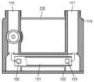
- FIG. 7 is a cross-sectional view of a conventional ultrasonic gas meter.
- a gas inlet 115 and an outlet 117 are provided on the top surface portion of the gas meter 116 formed in a rectangular box shape.
- the inflow port 115 and the outflow port 117 are connected by a gas flow path member 119 formed in a U-shaped cylindrical shape.
- the measurement channel 101 for measuring the gas flow rate is installed on the bottom surface portion 120 of the U-shaped channel based on the propagation time of the ultrasonic wave.
- the measurement channel 101 includes an ultrasonic transducer 102 on the upstream side and an ultrasonic transducer 103 on the downstream side so as to face each other.
- the present invention has been made in view of such problems, and the shape of the measurement flow path and the connection configuration of the measurement circuit and the ultrasonic transducer are adapted to the piping, installation location, application, etc. for connecting the flow meter. It is an object of the present invention to provide an ultrasonic flow rate measuring device that does not need to be changed.
- the present invention relates to an ultrasonic flow rate measuring device, a measurement channel through which a fluid to be measured flows, and a pair of ultrasonic transducers attached to the measurement channel in a direction in which an ultrasonic propagation path is V-shaped. And. Also, a measurement circuit that measures the propagation time of ultrasonic waves between a pair of ultrasonic transducers and measures the flow rate of the fluid to be measured, and an inlet that is provided on the inlet side of the measurement flow path and stabilizes the flow of the fluid to be measured Side rectifier. Furthermore, an outlet side connection part provided on the outlet side of the measurement flow path and a signal extraction part that outputs a flow rate value measured by the measurement circuit are provided.
- FIG. 1 is a cross-sectional view showing the configuration of the ultrasonic flow rate measuring apparatus according to the first embodiment of the present invention.
- FIG. 2 is a cross-sectional view showing a state where the ultrasonic flow rate measuring device according to the first embodiment of the present invention is attached to the meter body.
- FIG. 3 is a cross-sectional view showing an example in which the ultrasonic flow rate measuring device according to the first embodiment of the present invention is attached to another meter body.
- FIG. 4 is a cross-sectional view showing an example in which the ultrasonic flow rate measuring device according to the first embodiment of the present invention is attached to a pipe.
- FIG. 5A is a plan view showing the configuration of the ultrasonic flow rate measuring apparatus according to the second embodiment of the present invention.
- FIG. 5B is a side view showing the configuration of the ultrasonic flow rate measuring apparatus according to the second embodiment of the present invention.
- FIG. 5C is a front view seen from the inlet side of the ultrasonic flow rate measuring apparatus according to the second embodiment of the present invention.
- FIG. 5D is a partial cross-sectional view of region A in FIG. 5A of the ultrasonic flow rate measuring apparatus according to the second embodiment of the present invention.
- FIG. 6 is a perspective view showing an appearance of an ultrasonic flow rate measuring apparatus according to the third embodiment of the present invention.
- FIG. 7 is a cross-sectional view of a conventional ultrasonic gas meter.
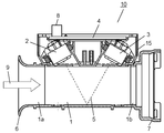
- FIG. 1 is a cross-sectional view showing a configuration of an ultrasonic flow rate measuring apparatus 10 according to the first embodiment of the present invention.
- the ultrasonic flow measuring device 10 includes a measurement flow path 1, a pair of ultrasonic transducers 2 and 3, a measurement circuit 4, an inlet side rectification unit 6, an outlet side connection unit 7, and a signal A take-out unit 8 is provided.
- Measured fluid flows through the measurement channel 1.
- the pair of ultrasonic transducers 2 and 3 are attached to the measurement channel 1 in a direction in which the ultrasonic propagation path is V-shaped.
- the measuring circuit 4 measures the flow time of the fluid to be measured by measuring the propagation time of the ultrasonic wave between the ultrasonic vibrators 2 and 3.
- the inlet side rectification unit 6 is provided on the inlet side of the measurement channel 1 and stabilizes the flow of the fluid to be measured.
- the outlet side connection portion 7 is provided on the outlet side of the measurement channel 1.
- the signal extraction unit 8 outputs the flow rate value measured by the measurement circuit 4 to the outside.
- the flow direction 9 indicated by the arrow indicates the flow direction of the fluid to be measured.
- the ultrasonic flow measuring device 10 As described above, the ultrasonic flow measuring device 10 according to the first embodiment assembles the pair of ultrasonic transducers 2 and 3 and the measurement circuit 4 as one device (measurement unit 15) in the measurement channel 1. ing. Further, the outlet side connection portion 7 is provided only on the outlet side 1b of the measurement channel 1. With these configurations, the ultrasonic flow measuring device 10 that is easy to install is realized. Connection with piping will be described later.
- the inlet side rectification unit 6 is provided on the inlet side 1a of the measurement channel 1 so that the fluid to be measured flows smoothly.
- the ultrasonic transducers 2 and 3 can be installed on the same surface side of the measurement flow path 1 (the upper surface side of the measurement flow path shown in the figure). Miniaturization is possible.
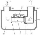
- FIG. 2 is a cross-sectional view showing a state in which the ultrasonic flow rate measuring device 10 according to the first embodiment of the present invention is attached to the meter main body 21.
- the meter body 21 has a meter inlet 25, a meter outlet 22, a buffer unit 23, and a lead-out pipe 24.
- the flow direction 9 indicated by the arrow indicates the flow direction of the fluid to be measured.
- the ultrasonic flow rate measuring device 10 is housed in a meter body 21 having a substantially rectangular parallelepiped shape.
- the inlet side of the ultrasonic flow measuring device 10 where the inlet-side rectifying unit 6 is provided opens to the buffer unit 23 of the meter main body 21.
- the lead-out tube 24 communicating with the meter outlet 22 of the meter main body 21 is airtightly joined to the outlet-side connecting portion 7 of the ultrasonic flow rate measuring device 10.
- the meter inlet 25 and the meter outlet 22 are arranged on the same surface of the meter main body 21.
- the fluid to be measured flows from the meter inlet 25 into the buffer unit 23 in the meter as indicated by an arrow (flow direction 9 of the fluid to be measured). Then, the fluid to be measured flows into the measurement flow channel 1 from the inlet-side rectification unit 6 provided in the ultrasonic flow measuring device 10, and the flow rate is measured by the ultrasonic vibrators 2 and 3 and the measurement circuit 4. Thereafter, the fluid to be measured is discharged from the meter outlet 22 via the outlet pipe 24.
- the ultrasonic flow rate measuring device 10 can be easily installed in a rectangular parallelepiped pipe.
- FIG. 3 is a cross-sectional view showing an example in which the ultrasonic flow rate measuring device 10 according to the first embodiment of the present invention is attached to another meter main body 31.
- the meter main body 31 has a meter inlet 32 and a meter outlet 33 arranged in a straight line.
- a lead-out pipe 34 communicates with the meter outlet 33.
- the ultrasonic flow measuring device 10 is connected to the outlet tube 34 in an airtight manner. According to this configuration, the ultrasonic flow rate measuring device 10 can be installed in the middle of a straight tubular pipe.
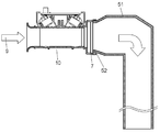
- FIG. 4 is a cross-sectional view showing an example in which the ultrasonic flow rate measuring device 10 according to the first embodiment of the present invention is attached to the pipe 51.
- the pipe 51 is open on one side.
- the outlet side connection part 7 of the ultrasonic flow rate measuring device 10 is airtightly connected to the end part 52 of the pipe 51. According to this configuration, the ultrasonic flow rate measuring device 10 can be installed in order to measure the flow rate of the fluid flowing into the pipe 51.
- a single ultrasonic flow measuring device 10 can be connected to various types of meters and pipes.
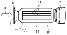
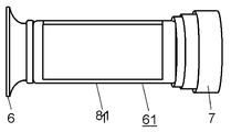
- FIG. 5A is a plan view showing a configuration of an ultrasonic flow rate measuring device 61 according to the second embodiment of the present invention
- FIG. 5B is a side view thereof
- FIG. 5C is a front view seen from the inlet side
- FIG. 5D is a partial cross-sectional view of region A in FIG. 5A.
- 5A to 5D show the configuration of the measurement flow path 81, the inlet-side rectifying unit 6, and the outlet-side connecting unit 7 in the configuration of the ultrasonic flow rate measuring device 61, but the first embodiment It is assumed that the measurement unit 15 described in the form is similarly provided.
- the pair of ultrasonic transducers 2 and 3 are arranged on the short side of the cross section of the measurement flow path 81 described later.
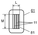
- the channel cross section of the measurement channel 81 has a rectangular shape with a short side dimension L and a long side dimension M.
- a plurality of reflectors 11 are provided so as to be parallel (longitudinal direction in FIG. 5C) to the long side of the cross section of the measurement flow channel 1 and parallel to the flow direction 9. (See FIGS. 5A and 5C).
- This reflection plate 11 can reduce the influence of a shift in propagation time between the ultrasonic wave that travels straight between the ultrasonic transducers 2 and 3 and the ultrasonic wave that reflects and travels on the wall surface of the measurement channel 81. Thereby, even if the distance between the ultrasonic transducers 2 and 3 is short, necessary measurement accuracy can be ensured. Further, the reflecting plate 11 has an effect of stabilizing the flow in the measurement channel 81 even if the entire length of the measurement channel 81 is short.
- the ultrasonic flow rate measuring device 61 of the present embodiment by having the reflecting plate 11, it is possible to realize a configuration in which the influence of the surroundings is less likely to affect the measurement accuracy.
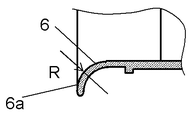
- the inner peripheral surface 6a of the inlet-side rectifying unit 6 of the ultrasonic flow rate measuring device 61 is formed of a curved surface.
- the radius of the curved surface satisfies R ⁇ L / 2. That is, the opening of the inlet-side rectifying unit 6 is configured to have a spread with a curve having a radius of 1/2 or more of the width dimension of the short side of the cross section of the measurement channel 81.
- the configuration of the above-described opening makes it difficult to be influenced by the surroundings and realizes stable measurement performance.
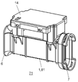
- FIG. 6 is a perspective view showing an appearance of an ultrasonic flow rate measuring device 71 according to the third embodiment of the present invention.
- the measurement flow paths 1 and 81, the inlet-side rectifying unit 6, the outlet-side connecting unit 7, and the circuit case 14 that houses the measuring circuit are all made of resin.
- the whole can be reduced in size, and the shape can be configured easily and accurately even with resin. Therefore, the entire apparatus can be made of resin, and the ultrasonic flow rate measuring apparatus 71 that is lighter can be realized. Therefore, the ultrasonic flow measuring device 71 can be easily installed in various places.
- ultrasonic flow measuring devices 10, 61, 71 described in the embodiments of the present invention ultrasonic waves that can be easily incorporated into various pipes and meter housings to ensure stable measurement accuracy.
- a flow meter can be realized.
- the installation property is versatile, and the measurement accuracy is hardly affected by the installation environment. Therefore, by incorporating the ultrasonic flow measuring devices 10, 61, 71, it is possible to realize an ultrasonic flow meter adapted to various installation environments in a short development period while suppressing development investment and mold investment.
- the present invention is useful as a flow measurement reference device, a gas meter, a water meter, or the like provided with an ultrasonic flow measurement device.
Landscapes
- Physics & Mathematics (AREA)
- Fluid Mechanics (AREA)
- General Physics & Mathematics (AREA)
- Electromagnetism (AREA)
- Measuring Volume Flow (AREA)
Abstract
L'invention concerne un dispositif de mesure de débit par ultrasons (10), comprenant un passage de mesure (1) à travers lequel un fluide à mesurer s'écoule, et une paire de vibrateurs à ultrasons (2, 3) montés sur le passage de mesure (1) suivant des directions telles que le trajet de propagation des ondes ultrasonores soit en forme de V. Le dispositif de mesure de débit par ultrasons comprend en outre un circuit de mesure (4) servant à mesurer le temps de propagation des ondes ultrasonores entre la paire de vibrateurs à ultrasons (2, 3) enfin de mesurer le débit du fluide à mesurer, et un élément de rectification côté entrée (6) se trouvant du côté entrée du passage de mesure (1) pour stabiliser l'écoulement du fluide à mesurer. Le dispositif de mesure de débit par ultrasons comprend en outre un élément de raccordement côté sortie (7) se trouvant du côté sortie du passage de mesure (1), et un élément d'extraction de signal (8) pour sortir la valeur du débit mesuré par le circuit de mesure (4).
Priority Applications (3)
| Application Number | Priority Date | Filing Date | Title |
|---|---|---|---|
| US13/821,915 US8984960B2 (en) | 2010-11-10 | 2011-11-02 | Ultrasonic flow rate measurement device having inlet side flow rectification part and outlet side coupling part |
| EP11840044.9A EP2639560B1 (fr) | 2010-11-10 | 2011-11-02 | Dispositif de mesure de débit par ultrasons |
| CN201180054446.7A CN103201599B (zh) | 2010-11-10 | 2011-11-02 | 超声波流量计量装置 |
Applications Claiming Priority (2)
| Application Number | Priority Date | Filing Date | Title |
|---|---|---|---|
| JP2010-251466 | 2010-11-10 | ||
| JP2010251466A JP2012103087A (ja) | 2010-11-10 | 2010-11-10 | 超音波流量計測ユニット |
Publications (1)
| Publication Number | Publication Date |
|---|---|
| WO2012063437A1 true WO2012063437A1 (fr) | 2012-05-18 |
Family
ID=46050606
Family Applications (1)
| Application Number | Title | Priority Date | Filing Date |
|---|---|---|---|
| PCT/JP2011/006135 WO2012063437A1 (fr) | 2010-11-10 | 2011-11-02 | Dispositif de mesure de débit par ultrasons |
Country Status (5)
| Country | Link |
|---|---|
| US (1) | US8984960B2 (fr) |
| EP (1) | EP2639560B1 (fr) |
| JP (1) | JP2012103087A (fr) |
| CN (1) | CN103201599B (fr) |
| WO (1) | WO2012063437A1 (fr) |
Cited By (4)
| Publication number | Priority date | Publication date | Assignee | Title |
|---|---|---|---|---|
| CN103035070A (zh) * | 2012-12-12 | 2013-04-10 | 山东冠翔仪表有限公司 | 小口径超声波智能水表 |
| WO2018216482A1 (fr) * | 2017-05-22 | 2018-11-29 | パナソニックIpマネジメント株式会社 | Compteur de gaz |
| JP2018194508A (ja) * | 2017-05-22 | 2018-12-06 | パナソニックIpマネジメント株式会社 | ガスメータ |
| JP2018194507A (ja) * | 2017-05-22 | 2018-12-06 | パナソニックIpマネジメント株式会社 | ガスメータ |
Families Citing this family (24)
| Publication number | Priority date | Publication date | Assignee | Title |
|---|---|---|---|---|
| CN102549396B (zh) * | 2009-10-01 | 2014-03-12 | 松下电器产业株式会社 | 超声波流量计量单元 |
| JP2014077750A (ja) * | 2012-10-12 | 2014-05-01 | Panasonic Corp | 超音波メータ |
| JP6060378B2 (ja) * | 2012-11-13 | 2017-01-18 | パナソニックIpマネジメント株式会社 | 流量計測装置 |
| JP6313048B2 (ja) * | 2014-01-09 | 2018-04-18 | パナソニック株式会社 | 計測ユニットおよびそれを備えた流量計測装置 |
| JP6330141B2 (ja) | 2014-02-07 | 2018-05-30 | パナソニックIpマネジメント株式会社 | ガス流量計 |
| CN104075758A (zh) * | 2014-06-09 | 2014-10-01 | 沈阳市航宇星仪表有限责任公司 | 超声波燃气表整流单元流道装置 |
| CN105043474A (zh) * | 2015-06-03 | 2015-11-11 | 成都千嘉科技有限公司 | 一种用于超声波流量计的新型流道结构 |
| US9618372B2 (en) * | 2015-09-04 | 2017-04-11 | Onicon Inc. | Transit time flow meter probe |
| JP6375519B2 (ja) | 2016-01-12 | 2018-08-22 | パナソニックIpマネジメント株式会社 | ガスメータ |
| US10222247B2 (en) * | 2016-07-07 | 2019-03-05 | Joseph Baumoel | Multiphase ultrasonic flow meter |
| PL3734236T3 (pl) * | 2016-07-13 | 2023-09-18 | Gwf Messsysteme Ag | Przepływomierz z kanałem pomiarowym |
| JP2018194506A (ja) * | 2017-05-22 | 2018-12-06 | パナソニックIpマネジメント株式会社 | 流量計測ユニット及びこれを用いたガスメータ |
| JP2018194505A (ja) * | 2017-05-22 | 2018-12-06 | パナソニックIpマネジメント株式会社 | 流量計測ユニット及びこれを用いたガスメータ |
| US10576978B2 (en) * | 2017-12-06 | 2020-03-03 | Cummins, Inc. | System and method for predictive engine and aftertreatment system control |
| US10473502B2 (en) | 2018-03-01 | 2019-11-12 | Joseph Baumoel | Dielectric multiphase flow meter |
| CN108414037A (zh) * | 2018-03-28 | 2018-08-17 | 上海中核维思仪器仪表有限公司 | 气体超声流量计测速流道 |
| CN108871475A (zh) * | 2018-05-04 | 2018-11-23 | 金卡智能集团股份有限公司 | 超声波计量装置 |
| DE102019008902A1 (de) * | 2018-12-28 | 2020-07-02 | Marquardt Gmbh | Baueinheit für eine Fluid-Leitung |
| CN109752056A (zh) * | 2018-12-29 | 2019-05-14 | 杭州先锋电子技术股份有限公司 | 一种超声波气体计量装置的流道结构及超声波计量表 |
| CN110988115A (zh) | 2019-12-26 | 2020-04-10 | 湖北锐意自控系统有限公司 | 一种超声波气体传感器 |
| CN113295222A (zh) * | 2020-02-21 | 2021-08-24 | 北京昌民技术有限公司 | 超声波流量计 |
| US11906338B2 (en) | 2020-06-05 | 2024-02-20 | Honeywell International Inc. | Flow measurement by combining 3L echo with delta time-of-flight cross correlation |
| US20230375386A1 (en) | 2020-10-14 | 2023-11-23 | Gwf Ag | Flowmeter |
| CN114323174B (zh) * | 2021-11-25 | 2023-06-06 | 山东大卫国际建筑设计有限公司 | 一种超声波流量计 |
Citations (8)
| Publication number | Priority date | Publication date | Assignee | Title |
|---|---|---|---|---|
| JPH09189591A (ja) * | 1996-01-10 | 1997-07-22 | Kaijo Corp | 流体測定装置 |
| JPH11201791A (ja) * | 1998-01-16 | 1999-07-30 | Agency Of Ind Science & Technol | 超音波流量計 |
| US6026693A (en) * | 1997-06-04 | 2000-02-22 | Baumoel; Douglas S. | Pipe spool section having square or rectangular cross-section for clamp on transducer and method for flow measurement |
| DE102006023479A1 (de) * | 2006-05-18 | 2007-11-22 | Siemens Ag | Strömungskanal zur Aufnahme des Durchflusssensors |
| EP1876427A1 (fr) * | 2006-07-05 | 2008-01-09 | Landis+Gyr GmbH | Débitmètre à ultrasons avec un dispositif déclencant des turbulences dans la zone d'arrivée |
| JP2009186430A (ja) | 2008-02-08 | 2009-08-20 | Toyo Gas Meter Kk | ガスメータ |
| JP2010066068A (ja) * | 2008-09-09 | 2010-03-25 | Tokyo Gas Co Ltd | 超音波流量計 |
| JP2010164558A (ja) * | 2008-12-18 | 2010-07-29 | Panasonic Corp | 流体の流れ計測装置 |
Family Cites Families (11)
| Publication number | Priority date | Publication date | Assignee | Title |
|---|---|---|---|---|
| GB2043900B (en) | 1979-02-27 | 1983-05-11 | Rolfe P | Flowmeter |
| FR2776379B1 (fr) * | 1998-03-19 | 2000-04-28 | Schlumberger Ind Sa | Compteur de gaz a filtres anti-poussieres |
| JP2000146645A (ja) * | 1998-11-12 | 2000-05-26 | Honda Electronic Co Ltd | 超音波流量計 |
| EP1612520B1 (fr) * | 2003-02-24 | 2019-01-16 | Panasonic Corporation | Dispositif de mesure de fluides a ultrasons |
| DE102004060065B4 (de) * | 2004-12-14 | 2016-10-20 | Robert Bosch Gmbh | Ultraschall Durchflussmesser mit Leitelementen |
| JP5041847B2 (ja) * | 2007-03-30 | 2012-10-03 | 旭有機材工業株式会社 | 流体制御装置 |
| JP2012021782A (ja) * | 2010-07-12 | 2012-02-02 | Panasonic Corp | 超音波流量計測ユニット |
| JP2012132801A (ja) * | 2010-12-22 | 2012-07-12 | Panasonic Corp | 超音波流量計 |
| JP4878653B1 (ja) * | 2011-01-28 | 2012-02-15 | 株式会社アツデン | 超音波流量測定装置 |
| JPWO2012137489A1 (ja) * | 2011-04-05 | 2014-07-28 | パナソニック株式会社 | 超音波流量計測装置 |
| JP4991963B1 (ja) * | 2011-11-16 | 2012-08-08 | 株式会社アツデン | 超音波式流量測定装置及びその使用方法 |
-
2010
- 2010-11-10 JP JP2010251466A patent/JP2012103087A/ja active Pending
-
2011
- 2011-11-02 CN CN201180054446.7A patent/CN103201599B/zh active Active
- 2011-11-02 US US13/821,915 patent/US8984960B2/en active Active
- 2011-11-02 WO PCT/JP2011/006135 patent/WO2012063437A1/fr active Application Filing
- 2011-11-02 EP EP11840044.9A patent/EP2639560B1/fr active Active
Patent Citations (8)
| Publication number | Priority date | Publication date | Assignee | Title |
|---|---|---|---|---|
| JPH09189591A (ja) * | 1996-01-10 | 1997-07-22 | Kaijo Corp | 流体測定装置 |
| US6026693A (en) * | 1997-06-04 | 2000-02-22 | Baumoel; Douglas S. | Pipe spool section having square or rectangular cross-section for clamp on transducer and method for flow measurement |
| JPH11201791A (ja) * | 1998-01-16 | 1999-07-30 | Agency Of Ind Science & Technol | 超音波流量計 |
| DE102006023479A1 (de) * | 2006-05-18 | 2007-11-22 | Siemens Ag | Strömungskanal zur Aufnahme des Durchflusssensors |
| EP1876427A1 (fr) * | 2006-07-05 | 2008-01-09 | Landis+Gyr GmbH | Débitmètre à ultrasons avec un dispositif déclencant des turbulences dans la zone d'arrivée |
| JP2009186430A (ja) | 2008-02-08 | 2009-08-20 | Toyo Gas Meter Kk | ガスメータ |
| JP2010066068A (ja) * | 2008-09-09 | 2010-03-25 | Tokyo Gas Co Ltd | 超音波流量計 |
| JP2010164558A (ja) * | 2008-12-18 | 2010-07-29 | Panasonic Corp | 流体の流れ計測装置 |
Non-Patent Citations (1)
| Title |
|---|
| See also references of EP2639560A4 * |
Cited By (5)
| Publication number | Priority date | Publication date | Assignee | Title |
|---|---|---|---|---|
| CN103035070A (zh) * | 2012-12-12 | 2013-04-10 | 山东冠翔仪表有限公司 | 小口径超声波智能水表 |
| WO2018216482A1 (fr) * | 2017-05-22 | 2018-11-29 | パナソニックIpマネジメント株式会社 | Compteur de gaz |
| JP2018194508A (ja) * | 2017-05-22 | 2018-12-06 | パナソニックIpマネジメント株式会社 | ガスメータ |
| JP2018194507A (ja) * | 2017-05-22 | 2018-12-06 | パナソニックIpマネジメント株式会社 | ガスメータ |
| US11060895B2 (en) | 2017-05-22 | 2021-07-13 | Panasonic Intellectual Property Management Co., Ltd. | Gas meter including a measurement unit in communication with a shutoff valve in an extended section within a meter body |
Also Published As
| Publication number | Publication date |
|---|---|
| EP2639560A1 (fr) | 2013-09-18 |
| US8984960B2 (en) | 2015-03-24 |
| EP2639560A4 (fr) | 2014-07-09 |
| EP2639560B1 (fr) | 2019-03-06 |
| US20130167655A1 (en) | 2013-07-04 |
| JP2012103087A (ja) | 2012-05-31 |
| CN103201599A (zh) | 2013-07-10 |
| CN103201599B (zh) | 2015-08-19 |
Similar Documents
| Publication | Publication Date | Title |
|---|---|---|
| WO2012063437A1 (fr) | Dispositif de mesure de débit par ultrasons | |
| JP2010164558A (ja) | 流体の流れ計測装置 | |
| TWI636238B (zh) | 直管式氣體流量計 | |
| WO2012164859A1 (fr) | Unité de mesure de débit à ultrasons et débitmètre de gaz la comprenant | |
| JP5510133B2 (ja) | 超音波式ガスメータ | |
| US8181536B2 (en) | Ultrasonic Flow Meter including a transducer having conical face | |
| JPWO2012137489A1 (ja) | 超音波流量計測装置 | |
| JP2012132801A (ja) | 超音波流量計 | |
| JP5728639B2 (ja) | 超音波流量計 | |
| US20200386590A1 (en) | Ultrasonic Flowmeter Element | |
| CN106030254A (zh) | 气体流量计 | |
| WO2017122239A1 (fr) | Compteur à gaz | |
| JP4936856B2 (ja) | 流量計 | |
| JP5816831B2 (ja) | 超音波流量計 | |
| JP6306434B2 (ja) | 超音波流量計 | |
| JP5259313B2 (ja) | 超音波流量計 | |
| JP2005189090A (ja) | 超音波式水道メータ | |
| JP6134899B2 (ja) | 流量計測ユニット | |
| JP2014077750A (ja) | 超音波メータ | |
| JP2009264906A (ja) | 流量計 | |
| JP2935944B2 (ja) | 超音波流量計ユニット | |
| JP2003114142A (ja) | 超音波式ガスメータ | |
| JP2020529599A (ja) | 流量計および測定チャネル | |
| CN108700447B (zh) | 气量计 | |
| JP4453341B2 (ja) | 超音波流量計 |
Legal Events
| Date | Code | Title | Description |
|---|---|---|---|
| 121 | Ep: the epo has been informed by wipo that ep was designated in this application |
Ref document number: 11840044 Country of ref document: EP Kind code of ref document: A1 |
|
| WWE | Wipo information: entry into national phase |
Ref document number: 13821915 Country of ref document: US |
|
| WWE | Wipo information: entry into national phase |
Ref document number: 2011840044 Country of ref document: EP |
|
| NENP | Non-entry into the national phase |
Ref country code: DE |