WO2012057097A1 - 印刷装置及び印刷方法 - Google Patents
印刷装置及び印刷方法 Download PDFInfo
- Publication number
- WO2012057097A1 WO2012057097A1 PCT/JP2011/074472 JP2011074472W WO2012057097A1 WO 2012057097 A1 WO2012057097 A1 WO 2012057097A1 JP 2011074472 W JP2011074472 W JP 2011074472W WO 2012057097 A1 WO2012057097 A1 WO 2012057097A1
- Authority
- WO
- WIPO (PCT)
- Prior art keywords
- medium
- print head
- printing
- unit
- heating unit
- Prior art date
- Legal status (The legal status is an assumption and is not a legal conclusion. Google has not performed a legal analysis and makes no representation as to the accuracy of the status listed.)
- Ceased
Links
Images
Classifications
-
- B—PERFORMING OPERATIONS; TRANSPORTING
- B41—PRINTING; LINING MACHINES; TYPEWRITERS; STAMPS
- B41J—TYPEWRITERS; SELECTIVE PRINTING MECHANISMS, i.e. MECHANISMS PRINTING OTHERWISE THAN FROM A FORME; CORRECTION OF TYPOGRAPHICAL ERRORS
- B41J15/00—Devices or arrangements of selective printing mechanisms, e.g. ink-jet printers or thermal printers, specially adapted for supporting or handling copy material in continuous form, e.g. webs
- B41J15/16—Means for tensioning or winding the web
- B41J15/165—Means for tensioning or winding the web for tensioning continuous copy material by use of redirecting rollers or redirecting nonrevolving guides
-
- B—PERFORMING OPERATIONS; TRANSPORTING
- B41—PRINTING; LINING MACHINES; TYPEWRITERS; STAMPS
- B41J—TYPEWRITERS; SELECTIVE PRINTING MECHANISMS, i.e. MECHANISMS PRINTING OTHERWISE THAN FROM A FORME; CORRECTION OF TYPOGRAPHICAL ERRORS
- B41J11/00—Devices or arrangements of selective printing mechanisms, e.g. ink-jet printers or thermal printers, for supporting or handling copy material in sheet or web form
- B41J11/0005—Curl smoothing, i.e. smoothing down corrugated printing material, e.g. by pressing means acting on wrinkled printing material
-
- D—TEXTILES; PAPER
- D06—TREATMENT OF TEXTILES OR THE LIKE; LAUNDERING; FLEXIBLE MATERIALS NOT OTHERWISE PROVIDED FOR
- D06C—FINISHING, DRESSING, TENTERING OR STRETCHING TEXTILE FABRICS
- D06C3/00—Stretching, tentering or spreading textile fabrics; Producing elasticity in textile fabrics
- D06C3/08—Stretching, tentering or spreading textile fabrics; Producing elasticity in textile fabrics by frames or like apparatus
Definitions
- the present invention relates to a printing apparatus and a printing method.
- printing may be performed on a medium of fabric such as a thin nylon cloth.
- JP 2000-351469 A Japanese Utility Model Publication No. 62-75946
- Fabric media is more likely to wrinkle than media such as paper due to humidity, pretreatment conditions, or the influence of tension applied during transport. Further, when using a thin cloth medium, particularly a nylon medium, wrinkles are particularly likely to occur.
- the medium when printing on a fabric medium, for example, the medium may be transported by attaching the medium to the surface of the belt member. In this case, if the wrinkled medium is attached to the belt member and conveyed, it may be difficult to perform printing appropriately.
- an object of the present invention is to provide a printing apparatus and a printing method that can solve the above-described problems.
- Patent Document 1 discloses a configuration that prevents wrinkles by using a specific-shaped roller.
- Patent Document 2 discloses a configuration for preventing wrinkles using an arcuate ironing shaft.
- these configurations are different from the configurations of the present invention.
- the present invention has the following configuration.
- (Configuration 1) A printing apparatus that performs printing on a fabric medium, a print head that performs printing on the medium, a transport mechanism that transports the medium to a position facing the print head, and transport that transports the medium Provided on the upstream side of the print head in the path, provided with a tension applying unit for applying tension to the medium in the upstream direction of the transport path, and provided between the tension applying unit and the print head in the transport path, A medium heating unit that heats the medium in contact with the medium, and the tension applying unit presses the medium against the medium heating unit by applying tension to the medium, and the medium heating unit heats the medium. While contacting the medium, the medium is wrinkled.
- This printing apparatus is, for example, an ink jet printer.
- the print head is an inkjet head, for example.
- the fabric medium is, for example, a thin cloth medium.
- the thin cloth medium is, for example, a cloth medium having a thickness of 2 mm or less (for example, 0.05 to 2 mm).
- the fabric medium may be a nylon medium such as a thin nylon cloth.
- the medium heating unit performs a humidity control operation for adjusting the humidity, which is the amount of water contained in the medium, by heating, for example. Then, for example, the medium is wrinkled by contacting the medium with a pressure corresponding to the tension applied to the tension applying unit. Further, the tension applying unit applies a tension of a size necessary for removing wrinkles to the medium using, for example, a tension bar.
- the medium heating unit can perform the humidity adjustment operation and the wrinkle removing operation while applying a high tension as necessary to the medium by the tension applying unit. Therefore, if constituted in this way, before performing printing by a print head, wrinkles of a medium can be taken out appropriately, for example. In addition, this makes it possible to appropriately perform printing on a fabric medium that is likely to be wrinkled.
- removing the wrinkle of the medium means, for example, contacting the medium to remove the wrinkle.
- an operation of removing wrinkles is performed by a member that is designed to remove wrinkles.
- removing the wrinkles of the medium does not necessarily mean that all the wrinkles are completely removed, but may be that some wrinkles are removed.
- the medium heating unit preferably heats the medium to a temperature of 30 to 60 ° C., for example.
- the image forming apparatus further includes a wrinkle removing unit that is provided between the medium heating unit and the print head in the conveyance path and takes a wrinkle of the medium by contacting the medium heated by the medium heating unit.
- the effect of removing wrinkles by the wrinkle removing unit can be further obtained, so that the wrinkles of the medium can be removed more appropriately. This also makes it possible to print more appropriately on the fabric medium.
- the tension applying unit presses the medium against the wrinkle removing unit, for example, by applying tension to the medium.
- the medium heating unit heats the medium to a temperature at which wrinkle removal can be appropriately performed even at the position of the wrinkle removal unit.
- the wrinkle removing unit is preferably provided in a position where the temperature of the medium heated by the medium heating unit does not drop excessively. More specifically, the relationship between the heating temperature by the medium heating unit and the installation position of the wrinkle removing unit is, for example, the material of the medium both in contact with the medium heating unit and in contact with the wrinkle removing unit. It is preferable to have a relationship that satisfies the above preferable temperature.
- the transport mechanism unit is a belt member that transports the medium attached to the surface, and has a belt member that transports the medium at least at a position facing the print head. It is provided on the upstream side of the belt member, and the medium is wrinkled at a position before being attached to the belt member.
- the medium can be properly wrinkled before being attached to the belt member. Therefore, a cloth medium such as a thin cloth can be stably conveyed in a state where wrinkles are removed. This also prevents problems from occurring due to wrinkles, and enables printing to be performed appropriately.
- the wrinkle removing portion is a member that contacts the medium over the entire width of the medium in the width direction of the medium, which is a direction orthogonal to the direction along the conveyance path.
- a curved member that is curved so that the central part of the medium protrudes in the direction toward the medium as compared with the one end and the other end.
- the wrinkle removing unit can properly remove the wrinkles of the medium.
- a bending member for example, a bending bar that is a bar-shaped member bent as described above can be suitably used.
- (Configuration 5) A printing method for performing printing on a fabric medium, wherein the tension applying unit is upstream of the print head in the transport path for transporting the medium to a position opposite to the print head that performs printing on the medium.
- the medium is applied with tension in the upstream direction of the conveyance path, and the medium is heated in contact with the medium by the medium heating unit between the tension application unit of the conveyance path and the print head.
- the medium is pressed against the medium heating unit, and the medium heating unit and the medium are brought into contact with each other while the medium is heated by the medium heating unit, so that the medium is wrinkled. In this way, for example, the same effect as that of Configuration 1 can be obtained.
- a printing apparatus that performs printing on a fabric medium, a print head that performs printing on the medium, a transport mechanism that transports the medium to a position opposite to the print head, and transport that transports the medium Provided on the upstream side of the print head in the path, provided with a tension applying unit for applying tension to the medium in the upstream direction of the transport path, and provided between the tension applying unit and the print head in the transport path, A medium heating unit that heats the medium, and a wrinkle removing unit that is provided between the medium heating unit and the print head in the conveyance path and removes wrinkles of the medium by contacting the medium heated by the medium heating unit. Prepare.
- the medium can be properly wrinkled before printing by the print head.
- this makes it possible to appropriately perform printing on a fabric medium that is likely to be wrinkled.
- the medium heating unit heats the medium so that the temperature of the medium at the time of contact with the wrinkle removing unit becomes the above preferable temperature corresponding to the material of the medium.
- (Structure 7) A printing method for printing on a fabric medium, wherein the tension applying unit is upstream of the print head in the transport path for transporting the medium to a position opposite to the print head for printing on the medium.
- the tension in the upstream direction of the transport path is applied to the medium, the medium is heated by the medium heating section between the tension applying section of the transport path and the print head, and the medium heating section and the print head of the transport path are heated.
- the medium heated by the medium heating unit and the wrinkle removing member are brought into contact with each other, whereby the medium is wrinkled by the wrinkle removing member. In this way, for example, the same effect as in Configuration 6 can be obtained.
- the medium when printing on a fabric medium, the medium can be properly wrinkled.
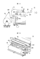
- FIG. 1A and 1B are diagrams illustrating an example of a configuration of a printing apparatus 10 according to an embodiment of the present invention.
- FIG. 1A is a side view illustrating an example of a configuration of a main part of the printing apparatus 10.
- FIG. 1B is a perspective view illustrating an example of a configuration of a main part of the printing apparatus 10.
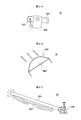
- 2A to 2C are diagrams illustrating an example of a detailed configuration of each unit of the printing apparatus 10.
- FIG. 2A shows an example of a detailed configuration of the tension applying unit 16.
- FIG. 2B shows an example of a detailed configuration of the iron heater 18.
- FIG. 2C shows an example of a detailed configuration of the wrinkle removing unit 20.
- FIG. 1A and 1B show an example of the configuration of a printing apparatus 10 according to an embodiment of the present invention.
- FIG. 1A is a side view illustrating an example of a configuration of a main part of the printing apparatus 10.
- FIG. 1B is a perspective view illustrating an example of a configuration of a main part of the printing apparatus 10. Note that, in the printing apparatus 10, portions not shown in FIGS. 1A and 1B have, for example, the same or similar configuration as a known printing apparatus.
- the printing apparatus 10 is an ink jet printer, and performs printing on a fabric medium 50 wound in a roll shape.
- the fabric may be a thin nylon fabric, for example.
- the printing apparatus 10 performs printing on the medium 50 by sequentially feeding and conveying the roll-shaped medium 50.
- the printing apparatus 10 includes a print head 12, a transport mechanism unit 14, a tension applying unit 16, an iron heater 18, and a wrinkle removing unit 20.
- the print head 12 is an inkjet head that performs printing on the medium 50.
- the transport mechanism unit 14 is a mechanism unit that transports the medium 50, and includes a belt member 202 and a plurality of rollers 204 and 206.
- the belt member 202 is provided at a position facing the print head 12, and conveys the medium 50 at least at a position facing the print head 12 by conveying the medium 50 attached to the surface.
- the plurality of rollers 204 and 206 are provided on the upstream side of the belt member 202 in the conveyance path of the medium 50, and convey the medium 50 fed from the roll to the belt member 202.
- the roller 204 is provided between the roll of the medium 50 and the tension applying unit 16, and supports the medium 50 upstream of the tension applying unit 16 in the transport direction.
- the roller 206 is provided on the downstream side of the conveyance path from the tension applying unit 16 and the iron heater 18, and the medium 50 is attached to the surface of the belt member 202 by sandwiching the medium 50 with the belt member 202.
- the transport mechanism unit 14 sequentially transports the medium 50 fed from the roll to a position facing the print head 12.
- the tension applying unit 16 is provided between the roller 204 and the iron heater 18 in the conveyance path of the medium 50, and presses a tension bar loaded with a predetermined weight against the medium 50, thereby removing the iron heater 18 and the wrinkle removal.
- a tension is applied to the medium 50 on the downstream side of the tension applying unit 16 in the transport path such as the position of the unit 20 in the upstream direction of the transport path. Thereby, the tension applying unit 16 presses the medium 50 against the iron heater 18 and the wrinkle removing unit 20.
- the iron heater 18 is an example of a medium heating unit, and is provided between the tension applying unit 16 and the wrinkle removing unit 20 in the conveyance path of the medium 50, and heats the medium 50 while being in contact with the medium 50. Thereby, the iron heater 18 performs a humidity control operation for adjusting the humidity of the medium 50 by heating, for example. In addition, by contacting the medium 50 with a pressure corresponding to the tension applied to the tension applying unit 16, for example, the medium 50 is wrinkled by the same operation as ironing the fabric.
- the wrinkle removing unit 20 is provided between the iron heater 18 and the roller 206 on the upstream side of the belt member 202 in the conveyance path of the medium 50, and comes into contact with the medium 50 heated by the iron heater 18. At the position before being attached to the member 202, the wrinkles of the medium 50 left behind by the iron heater 18 are removed.
- the medium 50 before being attached to the belt member 202, the medium 50 can be appropriately wrinkled. For this reason, even when the medium 50 of a cloth such as a thin cloth is used, the medium 50 can be stably conveyed in a wrinkled state. This also prevents problems from occurring due to wrinkles, and enables printing to be performed appropriately.
- the iron heater 18 preferably heats the medium 50 to 30 to 60 ° C., for example.
- the wrinkle removing unit 20 is provided at a position where it can come into contact with the medium 50 while the temperature of the medium 50 is within this range. If comprised in this way, the wrinkle of the medium 50 can be taken more appropriately.
- the tension applying unit 16 applies a tension of a size necessary for removing wrinkles by the iron heater 18 and the wrinkle removing unit 20 to the medium, for example, with a tension bar.
- the iron heater 18 preferably heats the medium 50 to a temperature corresponding to the material of the medium 50.
- FIG. 2A to 2C show an example of a detailed configuration of each unit of the printing apparatus 10.
- FIG. 2A shows an example of a detailed configuration of the tension applying unit 16.
- the tension applying unit 16 includes a tension bar 302, an arm 304, and a weight 306.
- the tension bar 302 is a rod-like member whose axial direction is the width direction of the medium 50, which is a direction orthogonal to the direction along the conveyance path of the medium 50, and is pressed against the medium 50 according to the load by the weight 306.
- the tension in the upstream direction of the transport path is applied to the medium 50 on the downstream side of the tension applying unit 16 in the transport path.
- the arm 304 is a support member that supports the tension bar 302.
- the weight 306 is a weight for setting a load for pressing the tension bar 302 against the medium 50. According to this example, it is possible to appropriately apply tension to the medium 50.
- FIG. 2B shows an example of a detailed configuration of the iron heater 18.
- the iron heater 18 has a heating element 404 inside a curved medium contact surface 402 that constitutes a part of the conveyance path of the medium 50, and contacts the medium 50 on the medium contact surface 402.
- the medium 50 is heated.
- the iron heater 18 adjusts the humidity of the medium 50, for example.
- the iron heater 18 further wrinkles the medium 50 by contacting the medium 50 with the curved medium contact surface 402. According to this example, the medium 50 can be appropriately wrinkled while the medium 50 is heated.
- FIG. 2C shows an example of a detailed configuration of the wrinkle removing unit 20.
- the wrinkle removing unit 20 includes a curved bar 502, a shaft portion 504, and a curved bar rotating mechanism unit 506.
- the curved bar 502 is an example of a curved member that contacts the medium 50 over the entire width of the medium 50 in the width direction of the medium 50.
- the curved bar 502 is curved so that, for example, the central portion in the width direction of the medium 50 protrudes in the direction toward the medium in comparison with the one end and the other end at the portion in contact with the medium 50.
- the shaft portion 504 is a rod-like member whose axial direction is the width direction of the medium 50, and supports the one end and the other end of the curved bar 502 to project the central portion of the curved bar 502 toward the medium 50.
- the bar 502 is supported.
- the bending bar rotating mechanism unit 506 is configured to adjust the position of the bending bar 502. In this example, the bending bar rotating mechanism unit 506 rotates the shaft portion 504 in accordance with the operation of the upper handle, so that the position of the bending bar 502 with respect to the central axis of the shaft portion 504 can be arbitrarily set within a range of 360 degrees. Adjust to position.
- the wrinkle removing unit 20 can appropriately remove the wrinkles of the medium 50 by bringing the curved bar 502 and the medium 50 into contact with each other. Further, by adjusting the position of the bending bar 502 by the bending bar rotating mechanism unit 506, the position of the bending bar 502 can be appropriately set at a position where wrinkles can be easily removed according to the configuration of the printing apparatus 10 and the characteristics of the medium 50. . Therefore, according to this example, the wrinkles of the medium 50 can be more appropriately removed.
Landscapes
- Engineering & Computer Science (AREA)
- Textile Engineering (AREA)
- Treatment Of Fiber Materials (AREA)
- Ink Jet (AREA)
- Registering, Tensioning, Guiding Webs, And Rollers Therefor (AREA)
- Coloring (AREA)
Abstract
布地の媒体への印刷時において、媒体のシワを適切に取る。 布地の媒体(50)に対して印刷を行う印刷装置(10)であって、印刷ヘッド(12)と、搬送機構部(14)と、媒体(50)が搬送される搬送経路における印刷ヘッド(12)よりも上流側に設けられて、搬送経路の上流側の方向へのテンションを媒体(50)に付与するテンション付与部(16)と、搬送経路においてテンション付与部(16)と印刷ヘッド(12)との間に設けられて、媒体(50)と接触した状態で媒体(50)を加熱する媒体加熱部であるアイロンヒータ(18)とを備え、テンション付与部(16)は、テンションを媒体(50)に付与することにより、媒体(50)を、アイロンヒータ(18)に押し当て、アイロンヒータ(18)は、媒体(50)を加熱しつつ媒体(50)と接触することにより、媒体(50)のシワを取る。
Description
本発明は、印刷装置及び印刷方法に関する。
近年、インクジェットプリンタの用途の広がりにより、印刷媒体(メディア)として、様々な媒体が用いられている。例えば、近年、ナイロンの薄布等の布地の媒体に対して印刷を行う場合がある。
布地の媒体は、湿度や前処理の状態、又は搬送時に加わるテンションの影響等により、紙等の媒体と比べ、シワが発生しやすい。また、薄布の媒体、特にナイロンの媒体を用いる場合には、特にシワが発生しやすくなる。
また、布地の媒体への印刷時においては、例えば、ベルト部材の表面に媒体を貼り付けて媒体の搬送を行う場合がある。この場合、シワの入った状態の媒体がベルト部材に貼り付けられ、搬送されると、適切に印刷を行うことが困難になるおそれがある。
そのため、従来、布地の媒体に印刷を行う場合において、シワの無い状態で安定に媒体の搬送を行うことが求められていた。そこで、本発明は、上記の課題を解決できる印刷装置及び印刷方法を提供することを目的とする。
尚、本発明と関連する先行技術文献を調査したところ、上記の特許文献1、2を発見した。特許文献1には、特定の形のローラを用いることでシワの発生を防ぐ構成が開示されている。また、特許文献2には、弓形のしごきシャフトを用いてシワを防止する構成が開示されている。しかし、これらの構成は、本発明と構成が異なるものである。
上記の課題を解決するために、本発明は、以下の構成を有する。
(構成1)布地の媒体に対して印刷を行う印刷装置であって、媒体に印刷を行う印刷ヘッドと、印刷ヘッドと対向する位置へ媒体を搬送する搬送機構部と、媒体が搬送される搬送経路における印刷ヘッドよりも上流側に設けられて、搬送経路の上流側の方向へのテンションを媒体に付与するテンション付与部と、搬送経路においてテンション付与部と印刷ヘッドとの間に設けられて、媒体と接触した状態で媒体を加熱する媒体加熱部とを備え、テンション付与部は、テンションを媒体に付与することにより、媒体を、媒体加熱部に押し当て、媒体加熱部は、媒体を加熱しつつ媒体と接触することにより、媒体のシワを取る。
(構成1)布地の媒体に対して印刷を行う印刷装置であって、媒体に印刷を行う印刷ヘッドと、印刷ヘッドと対向する位置へ媒体を搬送する搬送機構部と、媒体が搬送される搬送経路における印刷ヘッドよりも上流側に設けられて、搬送経路の上流側の方向へのテンションを媒体に付与するテンション付与部と、搬送経路においてテンション付与部と印刷ヘッドとの間に設けられて、媒体と接触した状態で媒体を加熱する媒体加熱部とを備え、テンション付与部は、テンションを媒体に付与することにより、媒体を、媒体加熱部に押し当て、媒体加熱部は、媒体を加熱しつつ媒体と接触することにより、媒体のシワを取る。
この印刷装置は、例えばインクジェットプリンタである。また、印刷ヘッドは、例えばインクジェットヘッドである。布地の媒体は、例えば薄布の媒体である。薄布の媒体とは、例えば、厚さが2mm以下(例えば、0.05~2mm)の布地の媒体である。布地の媒体は、ナイロンの薄布等のナイロンの媒体であってよい。
また、媒体加熱部は、例えば、媒体に含まれる水分量である湿度を加熱により調節する調湿動作を行う。そして、例えば、テンション付与部に付与されたテンションに応じた圧力で媒体と接触することにより、媒体のシワを取る。また、テンション付与部は、例えば、テンションバーにより、シワを取るために必要な大きさのテンションを媒体に付与する。
このように構成した場合、例えば、テンション付与部により必要に応じた高テンションを媒体に付与しつつ、媒体加熱部により、媒体の調湿の動作、及びシワを取る動作を行うことができる。そのため、このように構成すれば、例えば、印刷ヘッドによる印刷を行う前に、媒体のシワを適切に取ることができる。また、これにより、シワの発生しやすい布地の媒体に対して、適切に印刷を行うことができる。
尚、媒体のシワを取るとは、例えば、シワを取るために媒体と接触することである。シワを取るためとは、例えば、設計上、シワを取る意図で設けられた部材により、シワを取る動作を行うことである。また、媒体のシワを取るとは、必ずしも全てのシワを完全の取ることではなく、一部のシワを取ることであってもよい。媒体加熱部は、媒体を、例えば、30~60℃となる温度に加熱することが好ましい。
(構成2)搬送経路において媒体加熱部と印刷ヘッドとの間に設けられて、媒体加熱部により加熱された媒体と接触することにより、媒体のシワを取るシワ取り部を更に備える。
このように構成すれば、例えば、シワ取り部によるシワ取りの効果が更に得られるため、媒体のシワをより適切に取ることができる。また、これにより、布地の媒体に対して、より適切に印刷を行うことができる。
尚、この場合、テンション付与部は、例えば、テンションを媒体に付与することにより、媒体を、シワ取り部にも押し当てる。媒体加熱部は、例えば、シワ取り部の位置においてもシワ取りを適切にできる温度に、媒体を加熱する。シワ取り部は、媒体加熱部により加熱された媒体の温度が低下し過ぎない範囲の位置内に設けられることが好ましい。より具体的に、媒体加熱部による加熱温度、及びシワ取り部の設置位置の関係は、例えば、媒体加熱部との接触時、及びシワ取り部との接触時のいずれにおいても、媒体の素材に応じた上記の好ましい温度となる関係とすることが好ましい。
(構成3)搬送機構部は、表面に貼り付けられた媒体を搬送するベルト部材であり、少なくとも印刷ヘッドと対向する位置において媒体を搬送するベルト部材を有し、シワ取り部は、搬送経路においてベルト部材よりも上流側に設けられ、ベルト部材に貼り付けられる前の位置において、媒体のシワを取る。
ベルト部材を用いて媒体の搬送を行う場合、シワがある状態で媒体が貼り付けられると、その後にシワを取ることは困難である。また、その結果、適切に印刷を行うことが困難になるおそれがある。
これに対し、このように構成すれば、例えば、ベルト部材に貼り付ける前に、媒体のシワを適切に取ることができる。そのため、薄布等の布の媒体を、シワを取った状態で安定して搬送することが可能となる。また、これにより、シワの影響で問題が発生することを防ぎ、適切に印刷を行うことが可能となる。
(構成4)シワ取り部は、搬送経路に沿った方向と直交する方向である媒体の幅方向において媒体の幅全体に渡って媒体と接触する部材であり、媒体と接触する部分において、幅方向の中央部が一端及び他端と比べて媒体に向かう方向へ突出するように湾曲している湾曲部材を有する。
このように構成すれば、シワ取り部により、媒体のシワを適切に取ることができる。湾曲部材としては、例えば、上記のように湾曲した棒状部材である湾曲バーを好適に用いることができる。
(構成5)布地の媒体に対して印刷を行う印刷方法であって、媒体に印刷を行う印刷ヘッドと対向する位置へ媒体を搬送する搬送経路の印刷ヘッドよりも上流側において、テンション付与部により、搬送経路の上流側の方向へのテンションを媒体に付与し、搬送経路のテンション付与部と印刷ヘッドとの間において、媒体加熱部により、媒体と接触した状態で媒体を加熱し、かつ、テンション付与部でテンションを媒体に付与することにより、媒体を、媒体加熱部に押し当て、媒体加熱部により媒体を加熱しつつ、媒体加熱部と媒体とを接触させることにより、媒体のシワを取る。このようにすれば、例えば、構成1と同様の効果を得ることができる。
(構成6)布地の媒体に対して印刷を行う印刷装置であって、媒体に印刷を行う印刷ヘッドと、印刷ヘッドと対向する位置へ媒体を搬送する搬送機構部と、媒体が搬送される搬送経路における印刷ヘッドよりも上流側に設けられて、搬送経路の上流側の方向へのテンションを媒体に付与するテンション付与部と、搬送経路においてテンション付与部と印刷ヘッドとの間に設けられて、媒体を加熱する媒体加熱部と、搬送経路において媒体加熱部と印刷ヘッドとの間に設けられて、媒体加熱部により加熱された媒体と接触することにより、媒体のシワを取るシワ取り部とを備える。
このように構成すれば、例えば、印刷ヘッドによる印刷を行う前に、媒体のシワを適切に取ることができる。また、これにより、シワの発生しやすい布地の媒体に対して、適切に印刷を行うことができる。尚、媒体加熱部は、例えば、シワ取り部との接触時の媒体の温度が媒体の素材に応じた上記の好ましい温度となるように、媒体を加熱する。
(構成7)布地の媒体に対して印刷を行う印刷方法であって、媒体に印刷を行う印刷ヘッドと対向する位置へ媒体を搬送する搬送経路の印刷ヘッドよりも上流側において、テンション付与部により、搬送経路の上流側の方向へのテンションを媒体に付与し、搬送経路のテンション付与部と印刷ヘッドとの間において、媒体加熱部により、媒体を加熱し、搬送経路の媒体加熱部と印刷ヘッドとの間において、媒体加熱部により加熱された媒体とシワ取り部材とを接触させることにより、シワ取り部材により、媒体のシワを取る。このようにすれば、例えば、構成6と同様の効果を得ることができる。
本発明によれば、例えば、布地の媒体への印刷時において、媒体のシワを適切に取ることができる。
以下、本発明に係る実施形態を、図面を参照しながら説明する。図1A及び図1Bは、本発明の一実施形態に係る印刷装置10の構成の一例を示す。図1Aは、印刷装置10の要部の構成の一例を示す側面図である。図1Bは、印刷装置10の要部の構成の一例を示す斜視図である。尚、印刷装置10において、図1A及び図1Bで図示を省略した部分は、例えば、公知の印刷装置と同一又は同様の構成を有する。
本例において、印刷装置10は、インクジェットプリンタであり、ロール状に巻かれた布地の媒体50に対して印刷を行う。この布地は、例えばナイロンの薄布であってよい。印刷装置10は、ロール状の媒体50を順次繰り出して搬送することにより、媒体50への印刷を行う。
また、本例において、印刷装置10は、印刷ヘッド12、搬送機構部14、テンション付与部16、アイロンヒータ18、及びシワ取り部20を備える。印刷ヘッド12は、媒体50に印刷を行うインクジェットヘッドである。搬送機構部14は、媒体50を搬送する機構部であり、ベルト部材202、及び複数のローラ204、206を有する。ベルト部材202は、印刷ヘッド12と対向する位置に設けられ、表面に貼り付けられた媒体50を搬送することにより、少なくとも印刷ヘッド12と対向する位置において、媒体50を搬送する。
複数のローラ204、206は、媒体50の搬送経路においてベルト部材202よりも上流側に設けられ、ロールから繰り出された媒体50を、ベルト部材202まで搬送する。本例において、ローラ204は、媒体50のロールとテンション付与部16との間に設けられ、テンション付与部16よりも搬送方向の上流側において、媒体50を支持する。また、ローラ206は、テンション付与部16及びアイロンヒータ18よりも搬送経路の下流側に設けられ、ベルト部材202との間に媒体50を挟むことにより、ベルト部材202の表面に媒体50を貼り付ける。以上の構成により、搬送機構部14は、ロールから繰り出した媒体50を、印刷ヘッド12と対向する位置へ順次搬送する。
テンション付与部16は、媒体50の搬送経路においてローラ204とアイロンヒータ18との間に設けられ、所定のウェイトで荷重をかけたテンションバーを媒体50に押し当てることにより、アイロンヒータ18及びシワ取り部20の位置等の搬送経路においてテンション付与部16よりも下流側にある媒体50に対し、搬送経路の上流側の方向へのテンションを付与する。また、これにより、テンション付与部16は、媒体50を、アイロンヒータ18及びシワ取り部20に押し当てる。
アイロンヒータ18は、媒体加熱部の一例であり、媒体50の搬送経路においてテンション付与部16とシワ取り部20との間に設けられて、媒体50と接触した状態で媒体50を加熱する。これにより、アイロンヒータ18は、例えば、媒体50の湿度を加熱により調節する調湿動作を行う。また、テンション付与部16に付与されたテンションに応じた圧力で媒体50と接触することで、例えば、布地にアイロンをかけるのと同様の動作により、媒体50のシワを取る。
シワ取り部20は、媒体50の搬送経路においてベルト部材202よりも上流側において、アイロンヒータ18とローラ206との間に設けられ、アイロンヒータ18により加熱された媒体50と接触することにより、ベルト部材202に貼り付けられる前の位置において、アイロンヒータ18で取り残した媒体50のシワを取る。
本例によれば、例えば、ベルト部材202に貼り付ける前に、媒体50のシワを適切に取ることができる。そのため、薄布等の布の媒体50を用いる場合においても、シワを取った状態で安定して媒体50を搬送できる。また、これにより、シワの影響で問題が発生することを防ぎ、適切に印刷を行うことが可能となる。
ここで、アイロンヒータ18は、媒体50を、例えば、30~60℃に加熱することが好ましい。また、シワ取り部20は、媒体50の温度がこの範囲にある間に媒体50と接触できる位置に設けられることが好ましい。このように構成すれば、媒体50のシワをより適切に取ることができる。また、テンション付与部16は、例えば、テンションバーにより、アイロンヒータ18及びシワ取り部20でシワを取るために必要な大きさのテンションを媒体に付与する。
また、媒体50としては、ナイロンの薄布以外の各種の布地の媒体50を用いてもよい。この場合、アイロンヒータ18は、媒体50の素材に応じた温度に媒体50を加熱することが好ましい。
以下、印刷装置10の各部の構成について、更に詳しく説明する。図2A~図2Cは、印刷装置10の各部の詳細な構成の一例を示す。図2Aは、テンション付与部16の詳細な構成の一例を示す。本例において、テンション付与部16は、テンションバー302、アーム304、及びウェイト306を有する。
テンションバー302は、媒体50の搬送経路に沿った方向と直交する方向である媒体50の幅方向を軸方向とする棒状部材であり、ウェイト306による荷重に応じて媒体50に押し当てられることにより、搬送経路においてテンション付与部16よりも下流側にある媒体50に対し、搬送経路の上流側の方向へのテンションを付与する。アーム304は、テンションバー302を支持する支持部材である。また、ウェイト306は、テンションバー302を媒体50へ押し当てる荷重を設定する重りである。本例によれば、媒体50に適切にテンションを付与できる。
図2Bは、アイロンヒータ18の詳細な構成の一例を示す。本例において、アイロンヒータ18は、媒体50の搬送経路の一部を構成する曲面状の媒体接触面402の内側に発熱体404を有しており、媒体接触面402において媒体50と接触することにより、媒体50を加熱する。これにより、アイロンヒータ18は、例えば、媒体50の調湿を行う。また、アイロンヒータ18は、更に、曲面状の媒体接触面402で媒体50と接触することにより、媒体50のシワを取る。本例によれば、媒体50を加熱しつつ、媒体50のシワを適切に取ることができる。
図2Cは、シワ取り部20の詳細な構成の一例を示す。本例において、シワ取り部20は、湾曲バー502、軸部504、及び湾曲バー回転機構ユニット506を有する。湾曲バー502は、媒体50の幅方向において媒体50の幅全体に渡って媒体50と接触する湾曲部材の一例である。本例において、湾曲バー502は、例えば、媒体50と接触する部分において、媒体50の幅方向の中央部が一端及び他端と比べて媒体に向かう方向へ突出するように湾曲している。
軸部504は、媒体50の幅方向を軸方向とする棒状部材であり、湾曲バー502の一端及び他端を支持することにより、湾曲バー502の中央部を媒体50の方向へ突出させて湾曲バー502を支持する。湾曲バー回転機構ユニット506は、湾曲バー502の位置を調整するための構成である。本例において、湾曲バー回転機構ユニット506は、上部のハンドルの操作に応じて軸部504を回転させることにより、軸部504の中心軸に対する湾曲バー502の位置を、360度の範囲で任意の位置に調整する。
本例によれば、例えば、湾曲バー502と媒体50とを接触させることにより、シワ取り部20により、媒体50のシワを適切に取ることができる。また、湾曲バー回転機構ユニット506により湾曲バー502の位置を調整することにより、印刷装置10の構成や媒体50の特性に応じて、シワを取りやすい位置に湾曲バー502の位置を適切に設定できる。そのため、本例によれば、媒体50のシワをより適切に取ることができる。
以上、本発明を実施形態を用いて説明したが、本発明の技術的範囲は上記実施形態に記載の範囲には限定されない。上記実施形態に、多様な変更又は改良を加えることが可能であることが当業者に明らかである。その様な変更又は改良を加えた形態も本発明の技術的範囲に含まれ得ることが、特許請求の範囲の記載から明らかである。
Claims (7)
- 布地の媒体に対して印刷を行う印刷装置であって、
前記媒体に印刷を行う印刷ヘッドと、
前記印刷ヘッドと対向する位置へ前記媒体を搬送する搬送機構部と、
前記媒体が搬送される搬送経路における前記印刷ヘッドよりも上流側に設けられて、前記搬送経路の上流側の方向へのテンションを前記媒体に付与するテンション付与部と、
前記搬送経路において前記テンション付与部と前記印刷ヘッドとの間に設けられて、前記媒体と接触した状態で前記媒体を加熱する媒体加熱部と
を備え、
前記テンション付与部は、前記テンションを前記媒体に付与することにより、前記媒体を、前記媒体加熱部に押し当て、
前記媒体加熱部は、前記媒体を加熱しつつ前記媒体と接触することにより、前記媒体のシワを取ることを特徴とする印刷装置。 - 前記搬送経路において前記媒体加熱部と前記印刷ヘッドとの間に設けられて、前記媒体加熱部により加熱された前記媒体と接触することにより、前記媒体のシワを取るシワ取り部を更に備えることを特徴とする請求項1に記載の印刷装置。
- 前記搬送機構部は、表面に貼り付けられた前記媒体を搬送するベルト部材であり、少なくとも前記印刷ヘッドと対向する位置において前記媒体を搬送するベルト部材を有し、
前記シワ取り部は、前記搬送経路において前記ベルト部材よりも上流側に設けられ、前記ベルト部材に貼り付けられる前の位置において、前記媒体のシワを取ることを特徴とする請求項2に記載の印刷装置。 - 前記シワ取り部は、
前記搬送経路に沿った方向と直交する方向である媒体の幅方向において前記媒体の幅全体に渡って前記媒体と接触する部材であり、前記媒体と接触する部分において、前記幅方向の中央部が一端及び他端と比べて前記媒体に向かう方向へ突出するように湾曲している湾曲部材を有することを特徴とする請求項2又は3に記載の印刷装置。 - 布地の媒体に対して印刷を行う印刷方法であって、
前記媒体に印刷を行う印刷ヘッドと対向する位置へ前記媒体を搬送する搬送経路の前記印刷ヘッドよりも上流側において、テンション付与部により、前記搬送経路の上流側の方向へのテンションを前記媒体に付与し、
前記搬送経路の前記テンション付与部と前記印刷ヘッドとの間において、媒体加熱部により、前記媒体と接触した状態で前記媒体を加熱し、
かつ、
前記テンション付与部で前記テンションを前記媒体に付与することにより、前記媒体を、前記媒体加熱部に押し当て、
前記媒体加熱部により前記媒体を加熱しつつ、前記媒体加熱部と前記媒体とを接触させることにより、前記媒体のシワを取ることを特徴とする印刷方法。 - 布地の媒体に対して印刷を行う印刷装置であって、
前記媒体に印刷を行う印刷ヘッドと、
前記印刷ヘッドと対向する位置へ前記媒体を搬送する搬送機構部と、
前記媒体が搬送される搬送経路における前記印刷ヘッドよりも上流側に設けられて、前記搬送経路の上流側の方向へのテンションを前記媒体に付与するテンション付与部と、
前記搬送経路において前記テンション付与部と前記印刷ヘッドとの間に設けられて、前記媒体を加熱する媒体加熱部と、
前記搬送経路において前記媒体加熱部と前記印刷ヘッドとの間に設けられて、前記媒体加熱部により加熱された前記媒体と接触することにより、前記媒体のシワを取るシワ取り部と
を備えることを特徴とする印刷装置。 - 布地の媒体に対して印刷を行う印刷方法であって、
前記媒体に印刷を行う印刷ヘッドと対向する位置へ前記媒体を搬送する搬送経路の前記印刷ヘッドよりも上流側において、テンション付与部により、前記搬送経路の上流側の方向へのテンションを前記媒体に付与し、
前記搬送経路の前記テンション付与部と前記印刷ヘッドとの間において、媒体加熱部により、前記媒体を加熱し、
前記搬送経路の前記媒体加熱部と前記印刷ヘッドとの間において、前記媒体加熱部により加熱された前記媒体とシワ取り部材とを接触させることにより、前記シワ取り部材により、前記媒体のシワを取ることを特徴とする印刷方法。
Priority Applications (2)
| Application Number | Priority Date | Filing Date | Title |
|---|---|---|---|
| JP2012540854A JP5626605B2 (ja) | 2010-10-25 | 2011-10-25 | 印刷装置及び印刷方法 |
| CN201180051607.7A CN103221602B (zh) | 2010-10-25 | 2011-10-25 | 打印装置和打印方法 |
Applications Claiming Priority (2)
| Application Number | Priority Date | Filing Date | Title |
|---|---|---|---|
| JP2010-238658 | 2010-10-25 | ||
| JP2010238658 | 2010-10-25 |
Publications (1)
| Publication Number | Publication Date |
|---|---|
| WO2012057097A1 true WO2012057097A1 (ja) | 2012-05-03 |
Family
ID=45993805
Family Applications (1)
| Application Number | Title | Priority Date | Filing Date |
|---|---|---|---|
| PCT/JP2011/074472 Ceased WO2012057097A1 (ja) | 2010-10-25 | 2011-10-25 | 印刷装置及び印刷方法 |
Country Status (3)
| Country | Link |
|---|---|
| JP (1) | JP5626605B2 (ja) |
| CN (1) | CN103221602B (ja) |
| WO (1) | WO2012057097A1 (ja) |
Cited By (1)
| Publication number | Priority date | Publication date | Assignee | Title |
|---|---|---|---|---|
| US20150022606A1 (en) * | 2013-07-18 | 2015-01-22 | Roland Dg Corporation | Tension fluctuation alleviating device for use in fabric printing apparatus |
Families Citing this family (3)
| Publication number | Priority date | Publication date | Assignee | Title |
|---|---|---|---|---|
| CN103685843A (zh) * | 2013-11-29 | 2014-03-26 | 杨伟 | 具有纸张防潮功能的复印设备 |
| CN114643791B (zh) * | 2020-12-21 | 2025-04-01 | 罗兰Dg有限公司 | 打印机 |
| CN114643787B (zh) * | 2022-03-22 | 2023-07-14 | 南京柏桓数码科技有限公司 | 一种数码喷墨纺织印花机 |
Citations (2)
| Publication number | Priority date | Publication date | Assignee | Title |
|---|---|---|---|---|
| JPH08311782A (ja) * | 1995-05-12 | 1996-11-26 | Konica Corp | インクジェット布帛捺染装置及びインクジェット布帛捺染方法 |
| JP2004277995A (ja) * | 2003-03-12 | 2004-10-07 | Hewlett-Packard Development Co Lp | 裏紙を当てていない布地の搬送及び状態調節システム |
Family Cites Families (3)
| Publication number | Priority date | Publication date | Assignee | Title |
|---|---|---|---|---|
| JP2006341405A (ja) * | 2005-06-07 | 2006-12-21 | Dainippon Printing Co Ltd | 印刷装置、印刷システム、プログラム及び印刷方法 |
| CN101513800A (zh) * | 2009-01-09 | 2009-08-26 | 青岛尤尼科技有限公司 | 织物喷墨打印装置 |
| CN101693426A (zh) * | 2009-10-27 | 2010-04-14 | 北京信通四方企业顾问有限公司 | 一种织物数码打印设备及其方法 |
-
2011
- 2011-10-25 JP JP2012540854A patent/JP5626605B2/ja active Active
- 2011-10-25 CN CN201180051607.7A patent/CN103221602B/zh active Active
- 2011-10-25 WO PCT/JP2011/074472 patent/WO2012057097A1/ja not_active Ceased
Patent Citations (2)
| Publication number | Priority date | Publication date | Assignee | Title |
|---|---|---|---|---|
| JPH08311782A (ja) * | 1995-05-12 | 1996-11-26 | Konica Corp | インクジェット布帛捺染装置及びインクジェット布帛捺染方法 |
| JP2004277995A (ja) * | 2003-03-12 | 2004-10-07 | Hewlett-Packard Development Co Lp | 裏紙を当てていない布地の搬送及び状態調節システム |
Cited By (2)
| Publication number | Priority date | Publication date | Assignee | Title |
|---|---|---|---|---|
| US20150022606A1 (en) * | 2013-07-18 | 2015-01-22 | Roland Dg Corporation | Tension fluctuation alleviating device for use in fabric printing apparatus |
| US9227441B2 (en) * | 2013-07-18 | 2016-01-05 | Roland Dg Corporation | Tension fluctuation alleviating device for use in fabric printing apparatus |
Also Published As
| Publication number | Publication date |
|---|---|
| CN103221602A (zh) | 2013-07-24 |
| JPWO2012057097A1 (ja) | 2014-05-12 |
| JP5626605B2 (ja) | 2014-11-19 |
| CN103221602B (zh) | 2015-07-08 |
Similar Documents
| Publication | Publication Date | Title |
|---|---|---|
| JP6668727B2 (ja) | 処理液塗布装置及び画像形成システム | |
| JP6417782B2 (ja) | 記録媒体加熱装置、印刷装置、前処理液塗布乾燥装置、及び印刷システム | |
| JP5076586B2 (ja) | エンボス加工装置 | |
| JP6287068B2 (ja) | インクジェットプリンタ用処理剤液塗布装置およびそれを備えた画像形成システム | |
| JP5626605B2 (ja) | 印刷装置及び印刷方法 | |
| JP2016055623A (ja) | 記録装置 | |
| KR101643854B1 (ko) | 보풀제거장치를 구비한 디지털 텍스타일 프린터 | |
| CN105856839B (zh) | 记录装置 | |
| EP2923844B1 (en) | Printing apparatus and cockle removing method | |
| JP5761858B2 (ja) | 枚葉電子写真印刷機の定着装置 | |
| JP6357893B2 (ja) | 塗布装置、塗布装置の制御方法、及び画像形成システム | |
| JP7358805B2 (ja) | インクジェット記録装置及びインクジェット記録方法 | |
| JP2022088510A (ja) | 印刷装置 | |
| JP6394026B2 (ja) | 印刷装置および蛇行解消方法 | |
| CN102673182B (zh) | 打印机 | |
| US6499394B1 (en) | Stencil printer | |
| JP5678551B2 (ja) | プリンタ | |
| JP7406180B2 (ja) | 加熱装置、液体吐出装置、画像形成装置、後処理装置及び搬送装置 | |
| WO2023248972A1 (ja) | 箔転写装置 | |
| JP2018140499A (ja) | 熱転写型印刷装置 | |
| JP2004299213A (ja) | サーマルプリンタ | |
| JP6314638B2 (ja) | 塗布装置及び画像形成システム | |
| KR101713821B1 (ko) | 열승화 인쇄용 원단의 발색장치 | |
| JP2021104598A (ja) | 加熱装置、液体吐出装置、画像形成装置、後処理装置及び搬送装置 | |
| JP2015221527A (ja) | 前処理装置 |
Legal Events
| Date | Code | Title | Description |
|---|---|---|---|
| 121 | Ep: the epo has been informed by wipo that ep was designated in this application |
Ref document number: 11836230 Country of ref document: EP Kind code of ref document: A1 |
|
| ENP | Entry into the national phase |
Ref document number: 2012540854 Country of ref document: JP Kind code of ref document: A |
|
| NENP | Non-entry into the national phase |
Ref country code: DE |
|
| 122 | Ep: pct application non-entry in european phase |
Ref document number: 11836230 Country of ref document: EP Kind code of ref document: A1 |