WO2012056887A1 - 冷凍サイクル装置 - Google Patents
冷凍サイクル装置 Download PDFInfo
- Publication number
- WO2012056887A1 WO2012056887A1 PCT/JP2011/073477 JP2011073477W WO2012056887A1 WO 2012056887 A1 WO2012056887 A1 WO 2012056887A1 JP 2011073477 W JP2011073477 W JP 2011073477W WO 2012056887 A1 WO2012056887 A1 WO 2012056887A1
- Authority
- WO
- WIPO (PCT)
- Prior art keywords
- pipe
- refrigerant
- refrigeration cycle
- bypass hole
- tube
- Prior art date
- Legal status (The legal status is an assumption and is not a legal conclusion. Google has not performed a legal analysis and makes no representation as to the accuracy of the status listed.)
- Ceased
Links
Images




Classifications
-
- F—MECHANICAL ENGINEERING; LIGHTING; HEATING; WEAPONS; BLASTING
- F25—REFRIGERATION OR COOLING; COMBINED HEATING AND REFRIGERATION SYSTEMS; HEAT PUMP SYSTEMS; MANUFACTURE OR STORAGE OF ICE; LIQUEFACTION SOLIDIFICATION OF GASES
- F25B—REFRIGERATION MACHINES, PLANTS OR SYSTEMS; COMBINED HEATING AND REFRIGERATION SYSTEMS; HEAT PUMP SYSTEMS
- F25B40/00—Subcoolers, desuperheaters or superheaters
-
- F—MECHANICAL ENGINEERING; LIGHTING; HEATING; WEAPONS; BLASTING
- F25—REFRIGERATION OR COOLING; COMBINED HEATING AND REFRIGERATION SYSTEMS; HEAT PUMP SYSTEMS; MANUFACTURE OR STORAGE OF ICE; LIQUEFACTION SOLIDIFICATION OF GASES
- F25B—REFRIGERATION MACHINES, PLANTS OR SYSTEMS; COMBINED HEATING AND REFRIGERATION SYSTEMS; HEAT PUMP SYSTEMS
- F25B2600/00—Control issues
- F25B2600/25—Control of valves
- F25B2600/2501—Bypass valves
Definitions
- the present invention relates to a refrigeration cycle apparatus having an internal heat exchanger used in a vapor compression refrigeration cycle of a vehicle air conditioner.
- a heat pump cycle that performs an air conditioning operation using a refrigerant such as carbon dioxide that has an internal heat exchanger as described in Patent Document 1.
- a cycle device the specific enthalpy of the evaporator inlet refrigerant is reduced and the refrigeration effect is increased by performing heat exchange between the high-temperature / high-pressure liquid-phase refrigerant and the low-temperature / low-pressure gas-phase refrigerant. This improves cycle efficiency and capacity.
- FIG. 1 A schematic flow diagram of a refrigeration cycle apparatus having a conventional internal heat exchanger is shown in FIG.
- an object of the present invention is to provide a refrigeration cycle apparatus capable of increasing the heat exchange amount of an internal heat exchanger as compared with the conventional one while maintaining high operation efficiency and operation capability.
- a first refrigeration cycle apparatus includes an inner pipe in which a refrigerant circulating in the refrigeration cycle flows from the evaporator outlet to the compressor inlet in the pipe, and the refrigerant condenses in the pipe.
- a double-tube internal heat exchanger composed of an outer tube flowing from the evaporator outlet to the evaporator inlet, and a bypass hole for allowing a part of the refrigerant flowing in the outer tube to flow into the inner tube It is formed on the wall surface of the inner pipe, and the bypass hole is given an expansion action for reducing the pressure of the refrigerant flowing into the bypass hole.
- the high-temperature and high-pressure liquid-phase refrigerant after passing through the condenser is divided into a low-temperature and low-pressure two-phase refrigerant that branches a part of the liquid-phase refrigerant and passes through the bypass hole.
- the degree of supercooling at the inlet of the expansion mechanism can be increased by exchanging heat with the low-temperature and low-pressure gas-phase refrigerant after passing through the evaporator.
- the opening area of the bypass hole is basically determined by the diameter of the bypass hole, the total opening area of the bypass hole can be easily set by forming a plurality of bypass holes having a certain hole diameter on the wall surface of the inner pipe. Is possible.
- the second refrigeration cycle apparatus includes an inner pipe in which a refrigerant circulating in the refrigeration cycle flows from the evaporator outlet to the compressor inlet in the pipe, and the refrigerant passes through the pipe from the condenser outlet to the evaporator inlet. And a bypass wall through which a part of the refrigerant flowing in the outer pipe flows into the inner pipe is provided on the inner wall of the inner pipe.
- a throttle mechanism is provided on the inner peripheral surface of the outer wall of the outer pipe and upstream of the bypass hole, and a throttle mechanism for reducing the cross-sectional area of the pipe in the pipe is provided. An expansion action for reducing the pressure of the flowing refrigerant is applied.
- the throttle mechanism in the present invention can be configured as an orifice plate provided on the inner peripheral surface of the outer wall of the outer tube, for example.
- the refrigerant pressure can be reduced to a desired pressure.
- the expansion effect on the refrigerant is mainly applied to the throttle mechanism, so that the bypass hole mainly performs the flow rate adjusting function.
- the high-temperature and high-pressure liquid phase refrigerant after passing through the condenser is branched from the liquid phase refrigerant and allowed to pass through the bypass hole.
- the degree of supercooling in the latter stage of the condenser can be increased.
- by suppressing the flow rate of the refrigerant passing through the evaporator to a low level it is possible to suppress the pressure loss of the refrigerant in the evaporator and increase the refrigeration capacity and the cycle efficiency. .
- the dryness of the refrigerant at the evaporator inlet can be kept low, thereby further improving the refrigeration efficiency and the cycle efficiency.
- the bypass hole is formed so that the hole diameter decreases from the outer peripheral surface of the inner tube toward the inner peripheral surface of the tube wall. May be.
- the ratio of the refrigerant flow rate that flows into the inner pipe from the outer pipe through the bypass hole is the refrigerant flow rate that flows in the outer pipe. Is preferably set to 5 to 35%.
- a differential pressure operating valve is provided on a tube wall surface of the inner tube.
- the valve opening pressure of the differential pressure operating valve is preferably set to 1.0 MPa or more. If the refrigerant pressure balance before and after the bypass hole becomes unstable, the refrigerant may flow backward through the bypass hole and deteriorate the performance of the refrigeration cycle. Therefore, by providing such a differential pressure operating valve, it is possible to set the pressure at the start of the bypass to a desired value, and the refrigerant flowing in the inner pipe flows back into the outer pipe through the bypass hole. Therefore, it is possible to realize a refrigeration cycle apparatus that eliminates the risk of performing stable operation and exhibits stable performance.
- a mode in which the refrigerant flowing in the inner pipe and the outer pipe is replaced can be adopted. That is, in the third refrigeration cycle apparatus according to the present invention, the refrigerant circulating in the refrigeration cycle flows through the pipe from the evaporator outlet to the compressor inlet, and the refrigerant passes through the pipe from the condenser outlet to the evaporator inlet.
- a bypass pipe for allowing a part of the refrigerant flowing in the inner pipe to flow into the outer pipe is formed on the pipe wall surface of the inner pipe. And an expansion action is applied to the bypass hole to reduce the pressure of the refrigerant flowing into the bypass hole.
- the fourth refrigeration cycle apparatus includes an outer pipe through which refrigerant circulating in the refrigeration cycle flows from the evaporator outlet to the compressor inlet in the pipe, and the refrigerant passes through the pipe from the condenser outlet to the evaporator inlet.
- a bypass wall through which a part of the refrigerant flowing in the pipe of the inner pipe flows into the pipe of the outer pipe has a double pipe type internal heat exchanger composed of an inner pipe flowing into the pipe
- a throttle mechanism is provided on the inner peripheral surface of the outer wall of the outer pipe and on the upstream side of the bypass hole. An expansion action for reducing the pressure of the flowing refrigerant is applied.
- the refrigerating capacity can be easily increased in combination with the increase in the degree of supercooling. It becomes possible to raise. That is, when improving the refrigerating capacity by increasing the degree of supercooling, the suction superheat degree of the compressor can be kept low, and the damage given to the piping members such as the compressor and the discharge hose from the compressor is minimized. It becomes possible.
- FIG. 1 It is a schematic flowchart of the refrigeration cycle apparatus concerning one embodiment of the present invention.
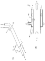
- the internal heat exchanger used in the refrigerating-cycle apparatus of FIG. 1 is shown, (A) is a perspective view, (B) is a schematic longitudinal cross-sectional view. 2 shows the internal heat exchanger of FIG. 2, (A) is a partially enlarged view in which the vicinity of the bypass hole is enlarged, and (B) is a schematic longitudinal sectional view for explaining a position where the bypass hole is formed.
- FIG. 1 is a schematic flow diagram of a refrigeration cycle apparatus 1 according to an embodiment of the present invention.
- the refrigerant circulates in the system, and the refrigerant flowing out of the condenser 2 flows into the evaporator 4 mainly through the expansion valve 8 via the outer pipe 3a of the double pipe type internal heat exchanger 3.
- a part of the refrigerant bypasses the evaporator 4 by flowing into the bypass hole 16 while expanding due to the expansion action of the bypass hole 16 formed on the tube wall surface of the inner tube 3b.
- the refrigerant evaporated in the evaporator 4 flows out of the evaporator 4, and then merges with the bypass flow flowing into the bypass hole 16 and flows into the compressor 5 via the inner pipe 3 b of the internal heat exchanger 3. .
- the refrigerant compressed in the compressor 5 flows into the condenser 2 and is condensed.
- the degree of superheat at the outlet of the evaporator 4 is less than the degree of superheat at the outlet of the inner pipe 3 b of the internal heat exchanger 3 (the degree of superheat at the inlet of the compressor 5).
- the length of the heat exchanger 3 (which affects the heat exchange amount) and the diameter of the bypass hole 16 (which affects the bypass amount) are set.
- FIG. 2 shows a double-pipe internal heat exchanger 13 used in the refrigeration cycle apparatus 1 of FIG. 1, wherein (A) is a perspective view and (B) is a schematic longitudinal sectional view.
- the refrigerant flowing into the outer pipe 13a from the condenser 2 through the inflow pipe 6 passes through the main flow flowing into the evaporator 4 through the outflow pipe 7 and the bypass hole 26 formed on the pipe wall surface of the inner pipe 13b. Branching into a bypass flow flowing into the internal flow path of the inner pipe 13b.
- the refrigerant that forms this bypass flow merges with the refrigerant flowing from the evaporator 4 into the inner pipe 13 b and flows out toward the compressor 5.
- the refrigerant flowing in the outer tube 13a exchanges heat with the refrigerant flowing in the inner tube 13b through the tube wall surface of the inner tube 13b.
- the bypass hole 26 is formed so that a flow resistance within a predetermined range is generated in the refrigerant flow passing therethrough, thereby having an expansion action for expanding the high-temperature / high-pressure refrigerant into a low-temperature / low-pressure refrigerant, A part of the low-pressure refrigerant is bypassed to join the low-temperature / low-pressure refrigerant after passing through the evaporator 4.
- the refrigerant is bypassed and merged, and the latent heat of evaporation of the bypassed refrigerant is used for cooling the high-pressure refrigerant, thereby improving cycle efficiency.
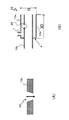
- FIG. 3 shows the internal heat exchanger of FIG. 2, (A) is a partially enlarged view in which the vicinity of the bypass hole 26 is enlarged, and (B) is a schematic longitudinal sectional view for explaining the position where the bypass hole 26 is formed. It is.
- the bypass hole 26 is formed so that the hole diameter decreases from the outer peripheral surface of the inner tube 13b toward the inner peripheral surface of the tube wall.
- the hole diameter of the bypass hole 26 (downstream opening diameter below the drawing) is set to a hole diameter such that the mass flow rate of the refrigerant passing through the hole is 5 to 35% of the mass flow rate of the refrigerant flowing through the internal flow path of the outer tube 13a. Has been.
- bypass hole 26 is preferably formed only on the upstream side of the inner tube 13b. Specifically, it is formed within a range (3D) that is three times as long as the outer diameter (D) of the outer tube 13a from the end surface 9 on the outlet side of the outer tube 13a toward the downstream side of the inner tube 13b. It is preferable.
- the bypass hole 26 is formed at such a position, it is possible to sufficiently secure an effective heat exchange area on the pipe wall surface of the inner pipe 13b and efficiently perform heat exchange of the refrigerant.
- FIG. 4 is a schematic longitudinal sectional view showing a modified example 23 of the internal heat exchanger 13 of FIG.
- a pedestal 10 is formed on the tube wall surface of the inner tube 23 b, and a differential pressure operating valve 12 that prevents the refrigerant from flowing back through the bypass hole 36 is installed via the pedestal 10.
- the differential pressure operating valve 12 includes a valve body, a disk valve, a coil spring, and a spring seat.
- the valve opening pressure required to open the differential pressure actuating valve 12 is set to 1.0 MPa or more. By this, the heat load is sufficiently increased, so that the apparatus for bypassing the refrigerant flow through the bypass hole 36 is used. The performance is improved.
- the flow resistance of the differential pressure operating valve 12 is set to a flow resistance such that the mass flow rate of the refrigerant passing through the bypass hole 36 is 5 to 35% of the mass flow rate of the refrigerant flowing through the internal flow path of the outer tube 23a. .
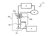
- FIG. 5 is a schematic flow diagram of the refrigeration cycle apparatus 11 according to another embodiment of the present invention.
- the refrigerant circulates in the system, and the refrigerant flowing out of the condenser 2 expands by the expansion action of the orifice 15 formed on the inner peripheral surface of the outer pipe 33a of the double pipe type internal heat exchanger 33.
- some refrigerant bypasses the evaporator 4 by flowing into a bypass hole 46 formed on the tube wall surface of the inner tube 33b.
- the refrigerant evaporated in the evaporator 4 flows out of the evaporator 4, and then merges with the branch flow that flows into the bypass hole 46 and flows into the compressor 5 via the inner pipe 33 b of the internal heat exchanger 33. .
- the refrigerant compressed in the compressor 5 flows into the condenser 2 and is condensed.
- the degree of superheat at the outlet of the evaporator 4 is less than or equal to the degree of superheat at the outlet of the inner pipe 33 b of the internal heat exchanger 33 (superheat degree at the inlet of the compressor 5).
- the length of the heat exchanger 33 (which affects the heat exchange amount) and the hole diameter of the bypass hole 46 (which affects the bypass amount) are set.
- FIG. 6 is a schematic longitudinal sectional view showing a double-pipe internal heat exchanger 43 used in the refrigeration cycle apparatus 11 of FIG.
- the refrigerant that has flowed into the outer tube 43a from the condenser 2 through the inflow tube 6 passes through the orifice 25 including the orifice plate 25a formed in the middle of the inner flow path of the outer tube 43a, and then passes through the outflow tube 7 to the evaporator. 4 and the bypass flow flowing into the internal flow path of the inner pipe 43b through the bypass hole 56 formed on the pipe wall surface of the inner pipe 43b.
- the refrigerant forming the bypass flow joins the refrigerant flowing from the evaporator 4 into the inner pipe 43 b and flows out toward the compressor 5.
- the refrigerant flowing in the outer tube 43a exchanges heat with the refrigerant flowing in the inner tube 43b via the wall surface of the inner tube 43b.
- the orifice 25 is formed so as to reduce the cross-sectional area of the flow path in the outer pipe 43a, and thereby has an expansion action for expanding the high-temperature / high-pressure refrigerant into the low-temperature / low-pressure refrigerant.
- the bypass hole 56 serves to bypass a part of the low-temperature / low-pressure refrigerant after being expanded by the orifice 25 and to join the low-temperature / low-pressure refrigerant after passing through the evaporator 4. In such a configuration, the refrigerant is bypassed and merged, and the latent heat of evaporation of the bypassed refrigerant is used for cooling the high-pressure refrigerant, thereby improving cycle efficiency.
- the refrigeration cycle apparatus according to the present invention is widely used in a vapor compression refrigeration cycle of a vehicle air conditioner.
Landscapes
- Engineering & Computer Science (AREA)
- Physics & Mathematics (AREA)
- Mechanical Engineering (AREA)
- Thermal Sciences (AREA)
- General Engineering & Computer Science (AREA)
- Heat-Exchange Devices With Radiators And Conduit Assemblies (AREA)
Abstract
冷凍サイクル内を循環する冷媒が管内を蒸発器出口から圧縮機入口へと流れる内管と、冷媒が管内を凝縮器出口から蒸発器入口へと流れる外管とからなる二重管式内部熱交換器を有し、外管の管内を流れる冷媒の一部を内管の管内に流入させるバイパス孔が、内管の管壁面上に形成されていることを特徴とする冷凍サイクル装置。高い運転効率および運転能力を保持しつつ、内部熱交換器の熱交換量を従来よりも高めることができる。
Description
本発明は、車両用空調装置の蒸気圧縮式冷凍サイクル等に用いられる、内部熱交換器を有する冷凍サイクル装置に関する。
二酸化炭素等の冷媒を用いて冷暖房運転を行うヒートポンプサイクルにおいて、特許文献1に記載されるような内部熱交換器を有するものが知られている。このようなサイクル装置においては、高温・高圧の液相冷媒と低温・低圧の気相冷媒との間で熱交換を行うことによって、蒸発器入口冷媒の比エンタルピを減少させ、冷凍効果を増加させることでサイクルの効率および能力の向上が図られている。従来の内部熱交換器を有する冷凍サイクル装置の概略フロー図を、図7に示す。
従来のサイクル装置に使用される内部熱交換器においては、熱交換量を増やし過ぎると、圧縮機の吸入過熱度が異常に高くなり、圧縮機および吐出ホースの耐久性に悪影響を及ぼす恐れがあった。このような悪影響を回避するために、内部熱交換器を運転するにあたっては、圧縮機の吸入過熱度を所定範囲内に抑えることができる程度に熱交換量の上限を設定する必要があった。
そこで本発明の課題は、高い運転効率および運転能力を保持しつつ、内部熱交換器の熱交換量を従来よりも高めることができる冷凍サイクル装置を提供することにある。
上記課題を解決するために、本発明に係る第1の冷凍サイクル装置は、冷凍サイクル内を循環する冷媒が管内を蒸発器出口から圧縮機入口へと流れる内管と、前記冷媒が管内を凝縮器出口から蒸発器入口へと流れる外管とからなる二重管式内部熱交換器を有し、前記外管の管内を流れる前記冷媒の一部を前記内管の管内に流入させるバイパス孔が前記内管の管壁面上に形成され、前記バイパス孔に、該バイパス孔内へと流入する冷媒の圧力を減少させる膨張作用が付与されていることを特徴とするものからなる。
このような本発明の冷凍サイクル装置においては、凝縮器を通過した後の高温高圧の液相冷媒を、当該液相冷媒の一部を分岐してバイパス孔を通過させた低温低圧の2相冷媒および蒸発器を通過した後の低温低圧の気相冷媒との間で熱交換させることによって、膨張機構の入口における過冷却度を高めることができる。このような本発明の冷凍サイクルによれば、蒸発器を通過する冷媒の流量を低く抑えることにより、蒸発器における冷媒の圧力損失を抑制し、冷凍能力およびサイクル効率を増加させることが可能となる。さらに、本発明の冷凍サイクルによれば、蒸発器入口における冷媒の乾き度を低く抑えることも可能であり、これによって冷凍効率およびサイクル効率のさらなる改善が図られる。
バイパス孔に膨張作用を適切に付与するためには、バイパス孔の開口面積を適正範囲に設定する必要がある。バイパス孔の開口面積は基本的にバイパス孔の孔径によって決まるが、一定の孔径を有するバイパス孔を内管の管壁面上に複数形成することによって、バイパス孔の総開口面積を簡便に設定することが可能である。
また、本発明に係る第2の冷凍サイクル装置は、冷凍サイクル内を循環する冷媒が管内を蒸発器出口から圧縮機入口へと流れる内管と、前記冷媒が管内を凝縮器出口から蒸発器入口へと流れる外管とからなる二重管式内部熱交換器を有し、前記外管の管内を流れる前記冷媒の一部を前記内管の管内に流入させるバイパス孔が前記内管の管壁面上に形成され、前記外管の管壁内周面上であって前記バイパス孔よりも上流側に管内の流路断面積を絞る絞り機構が設けられ、該絞り機構に前記外管の管内を流れる前記冷媒の圧力を減少させる膨張作用が付与されていることを特徴とするものからなる。本発明における絞り機構は、例えば外管の管壁内周面に設けられるオリフィス板として構成することができる。当該オリフィス板の寸法を適切に設計することにより、冷媒の圧力を所望の圧力まで減少させることが可能となる。このような絞り機構が設けられる場合には、冷媒に対する膨張作用は主として絞り機構に付与されるので、バイパス孔は主として流量調整作用を果たすこととなる。
このような本発明に係る第2の冷凍サイクル装置においては、凝縮器を通過した後の高温高圧の液相冷媒を、当該液相冷媒の一部を分岐してバイパス孔を通過させた低温低圧の2相冷媒および蒸発器を通過した後の低温低圧の気相冷媒との間で熱交換させることによって、凝縮器の後段における過冷却度を高めることができる。このような本発明の冷凍サイクルによれば、蒸発器を通過する冷媒の流量を低く抑えることにより、蒸発器における冷媒の圧力損失を抑制し、冷凍能力およびサイクル効率を増加させることが可能となる。さらに、本発明の冷凍サイクルによれば、蒸発器入口における冷媒の乾き度を低く抑えることも可能であり、これによって冷凍効率およびサイクル効率のさらなる改善が図られる。
本発明に係る第1および第2の冷凍サイクル装置において、系内の異物によってバイパス孔が閉塞されることを回避するために、バイパス孔を複数設けることが好ましい。さらにエンドミル等の治具にて外から内に向かって穿孔加工を行う際の便宜から、バイパス孔を、内管の管壁外周面から管壁内周面に向けて孔径が減少するように形成してもよい。
本発明に係る第1および第2の冷凍サイクル装置において、前記バイパス孔を介して前記外管の管内から前記内管の管内に流入する冷媒流量の割合が、前記外管の管内を流れる冷媒流量の5~35%に設定されていることが好ましい。このような流量割合で冷媒をバイパスさせることにより、冷凍サイクルのシステム性能を不安定にすることなく、膨張機構における過冷却度を高めることができる。
本発明に係る第1および第2の冷凍サイクル装置において、前記内管の管壁面上に差圧作動弁が設けられていることが好ましい。差圧作動弁の開弁圧は1.0MPa以上に設定されていることが好ましい。バイパス孔の前後における冷媒圧力のバランスが不安定になると、冷媒がバイパス孔を通して逆流して冷凍サイクルの性能を悪化させるおそれがある。そこで、このような差圧作動弁が設けられることにより、バイパス開始の圧力を所望の値に設定することができるとともに、内管の管内を流れる冷媒がバイパス孔を介して外管の管内に逆流する恐れが解消され安定した性能を発揮する冷凍サイクル装置が実現可能となる。
また、本発明に係る冷凍サイクル装置の変形例として、内管と外管内を流れる冷媒を入れ替えた態様も採用可能である。すなわち本発明に係る第3の冷凍サイクル装置は、冷凍サイクル内を循環する冷媒が管内を蒸発器出口から圧縮機入口へと流れる外管と、前記冷媒が管内を凝縮器出口から蒸発器入口へと流れる内管とからなる二重管式内部熱交換器を有し、前記内管の管内を流れる前記冷媒の一部を前記外管の管内に流入させるバイパス孔が前記内管の管壁面上に形成され、前記バイパス孔に、該バイパス孔内へと流入する冷媒の圧力を減少させる膨張作用が付与されていることを特徴とするものからなる。
また、本発明に係る第4の冷凍サイクル装置は、冷凍サイクル内を循環する冷媒が管内を蒸発器出口から圧縮機入口へと流れる外管と、前記冷媒が管内を凝縮器出口から蒸発器入口へと流れる内管とからなる二重管式内部熱交換器を有し、前記内管の管内を流れる前記冷媒の一部を前記外管の管内に流入させるバイパス孔が前記内管の管壁面上に形成され、前記外管の管壁内周面上であって前記バイパス孔よりも上流側に管内の流路断面積を絞る絞り機構が設けられ、該絞り機構に前記内管の管内を流れる前記冷媒の圧力を減少させる膨張作用が付与されていることを特徴とするものからなる。
このような本発明に係る第3および第4の冷凍サイクル装置においても、前述した第1および第2の冷凍サイクル装置と同様の付加的構成を追加することが可能である。
本発明に係る冷凍サイクル装置によれば、蒸発器を通過する冷媒の流量を低く抑えることにより蒸発器における冷媒の圧力損失を抑制可能であるので、過冷却度の増加と相まって容易に冷凍能力を高めることが可能となる。すなわち、過冷却度増加によって冷凍能力の改善を図る際に、圧縮機の吸入過熱度を低く抑えることができ、圧縮機や圧縮機からの吐出ホース等の配管部材に与えられるダメージを極力小さく抑えることが可能となる。
以下に、本発明の望ましい実施の形態を、図面を参照して説明する。
図1は、本発明の一実施態様に係る冷凍サイクル装置1の概略フロー図である。系内には冷媒が循環しており、凝縮器2から流出した冷媒は、二重管式の内部熱交換器3の外管3aを経由し、主として膨張弁8を通して蒸発器4に流入するが、一部の冷媒は内管3bの管壁面上に形成されたバイパス孔16の膨張作用により膨張しながらバイパス孔16内に流入することにより、蒸発器4をバイパスする。蒸発器4内で蒸発した冷媒は、蒸発器4から流出した後、バイパス孔16内に流入したバイパス流れと合流して内部熱交換器3の内管3bを経由し、圧縮機5に流入する。圧縮機5内で圧縮された冷媒は、凝縮器2に流入して凝縮される。このような冷凍サイクル装置1において、蒸発器4の出口における過熱度が、内部熱交換器3の内管3bの出口における過熱度(圧縮機5の入口における過熱度)以下になるように、内部熱交換器3の長さ(熱交換量に影響する)およびバイパス孔16の孔径(バイパス量に影響する)が設定されている。
図1は、本発明の一実施態様に係る冷凍サイクル装置1の概略フロー図である。系内には冷媒が循環しており、凝縮器2から流出した冷媒は、二重管式の内部熱交換器3の外管3aを経由し、主として膨張弁8を通して蒸発器4に流入するが、一部の冷媒は内管3bの管壁面上に形成されたバイパス孔16の膨張作用により膨張しながらバイパス孔16内に流入することにより、蒸発器4をバイパスする。蒸発器4内で蒸発した冷媒は、蒸発器4から流出した後、バイパス孔16内に流入したバイパス流れと合流して内部熱交換器3の内管3bを経由し、圧縮機5に流入する。圧縮機5内で圧縮された冷媒は、凝縮器2に流入して凝縮される。このような冷凍サイクル装置1において、蒸発器4の出口における過熱度が、内部熱交換器3の内管3bの出口における過熱度(圧縮機5の入口における過熱度)以下になるように、内部熱交換器3の長さ(熱交換量に影響する)およびバイパス孔16の孔径(バイパス量に影響する)が設定されている。
図2は、図1の冷凍サイクル装置1において用いられる二重管式の内部熱交換器13を示しており、(A)は斜視図、(B)は概略縦断面図である。凝縮器2から流入管6を通して外管13aに流入した冷媒は、流出管7を介して蒸発器4へと流入する主流れと、内管13bの管壁面上に形成されたバイパス孔26を介して内管13bの内部流路に流入するバイパス流れとに分岐される。このバイパス流れを形成する冷媒は、内管13b内に蒸発器4から流入する冷媒と合流して、圧縮機5に向けて流出する。
図2において、外管13a内を流れる冷媒は、内管13b内を流れる冷媒との間で、内管13bの管壁面を介して熱交換を行う。バイパス孔26は、通過する冷媒流れに所定範囲内の流動抵抗が生じるように形成されており、これによって高温・高圧冷媒を低温・低圧冷媒へと膨張させる膨張作用を有するとともに、膨張した低温・低圧冷媒の一部をバイパスさせて、蒸発器4を通過した後の低温・低圧冷媒に合流させる働きをする。このような構成にて冷媒をバイパスおよび合流させ、バイパスした冷媒の持つ蒸発潜熱を高圧冷媒の冷却に利用することによって、サイクル効率の向上が図られている。
図3は、図2の内部熱交換器を示しており、(A)はバイパス孔26近傍を拡大した部分拡大図、(B)はバイパス孔26が形成される位置を説明する概略縦断面図である。バイパス孔26は、図3(A)に示すように、内管13bの管壁外周面から管壁内周面に向けて孔径が減少するように形成されている。バイパス孔26の孔径(図面下方の下流側開口径)は、孔を通過する冷媒の質量流量が外管13aの内部流路を流れる冷媒の質量流量の5~35%となるような孔径に設定されている。
図3のバイパス孔26は内管13bの管壁面上に1つだけ形成されているが、孔の目詰まりを防止する観点からは複数形成されていることが好ましい。さらに、図3(B)に示すように、バイパス孔26は内管13bの上流側にのみ形成されるのがよい。具体的には、外管13aの出口側の端面9から内管13bの下流側に向けて、外管13aの外径(D)の3倍の長さ(3D)の範囲内に形成されることが好ましい。このような位置にバイパス孔26を形成することにより、内管13bの管壁面上の有効な熱交換面積を十分に確保し、冷媒の熱交換を効率的に行うことができる。
図4は、図2の内部熱交換器13の変形例23を示す概略縦断面図である。内管23bの管壁面上には台座10が形成され、バイパス孔36を介して冷媒が逆流することを防止する差圧作動弁12が台座10を介して設置されている。差圧作動弁12は、弁本体、ディスク弁、コイルばねおよびばね受座から構成されている。差圧作動弁12を開放させるのに必要な開弁圧は1.0MPa以上に設定されており、これによって熱負荷が十分に高められることで、バイパス孔36を通した冷媒流れのバイパスによる装置性能の向上が図られている。差圧作動弁12の流動抵抗は、バイパス孔36を通過する冷媒の質量流量が外管23aの内部流路を流れる冷媒の質量流量の5~35%となるような流動抵抗に設定されている。
図5は、本発明の他の実施態様に係る冷凍サイクル装置11の概略フロー図である。系内には冷媒が循環しており、凝縮器2から流出した冷媒は、二重管式の内部熱交換器33の外管33a内周面上に形成されたオリフィス15の膨張作用により膨張して主として蒸発器4に流入するが、一部の冷媒は内管33bの管壁面上に形成されたバイパス孔46内に流入することにより蒸発器4をバイパスする。蒸発器4内で蒸発した冷媒は、蒸発器4から流出した後、バイパス孔46内に流入した分岐流と合流して内部熱交換器33の内管33bを経由し、圧縮機5に流入する。圧縮機5内で圧縮された冷媒は、凝縮器2に流入して凝縮される。このような冷凍サイクル装置1において、蒸発器4の出口における過熱度が、内部熱交換器33の内管33bの出口における過熱度(圧縮機5の入口における過熱度)以下になるように、内部熱交換器33の長さ(熱交換量に影響する)およびバイパス孔46の孔径(バイパス量に影響する)が設定されている。
図6は、図5の冷凍サイクル装置11において用いられる二重管式の内部熱交換器43を示す概略縦断面図である。凝縮器2から流入管6を通して外管43aに流入した冷媒は、外管43aの内部流路の途中に形成されたオリフィス板25aからなるオリフィス25を通過した後、流出管7を介して蒸発器4へと流入する主流れと、内管43bの管壁面上に形成されたバイパス孔56を介して内管43bの内部流路に流入するバイパス流れとに分岐される。このバイパス流れを形成する冷媒は、内管43b内に蒸発器4から流入する冷媒と合流して、圧縮機5に向けて流出する。
図6において、外管43a内を流れる冷媒は、内管43b内を流れる冷媒との間で、内管43bの管壁面を介して熱交換を行う。オリフィス25は、外管43a内の流路断面積を絞るように形成されており、これによって高温・高圧冷媒を低温・低圧冷媒へと膨張させる膨張作用を有している。バイパス孔56は、オリフィス25により膨張した後の低温・低圧冷媒の一部をバイパスさせて、蒸発器4を通過した後の低温・低圧冷媒に合流させる働きをする。このような構成にて冷媒をバイパスおよび合流させ、バイパスした冷媒の持つ蒸発潜熱を高圧冷媒の冷却に利用することによって、サイクル効率の向上が図られている。
本発明に係る冷凍サイクル装置は、車両用空調装置の蒸気圧縮式冷凍サイクル等に広く用いられる。
1、11、51 冷凍サイクル装置
2 凝縮器
3、13、23、33、43、53 内部熱交換器
3a、13a、23a、33a、43a、53a 外管
3b、13b、23b、33b、43b、53b 内管
4 蒸発器
5 圧縮機
6 流入管
7 流出管
8 膨張弁
9 端面
10 台座
12 差圧作動弁
15、25 オリフィス
16、26、36、46、56 バイパス孔
25a オリフィス板
D 外管の外径
2 凝縮器
3、13、23、33、43、53 内部熱交換器
3a、13a、23a、33a、43a、53a 外管
3b、13b、23b、33b、43b、53b 内管
4 蒸発器
5 圧縮機
6 流入管
7 流出管
8 膨張弁
9 端面
10 台座
12 差圧作動弁
15、25 オリフィス
16、26、36、46、56 バイパス孔
25a オリフィス板
D 外管の外径
Claims (9)
- 冷凍サイクル内を循環する冷媒が管内を蒸発器出口から圧縮機入口へと流れる内管と、前記冷媒が管内を凝縮器出口から蒸発器入口へと流れる外管とからなる二重管式内部熱交換器を有し、前記外管の管内を流れる前記冷媒の一部を前記内管の管内に流入させるバイパス孔が前記内管の管壁面上に形成され、前記バイパス孔に、該バイパス孔内へと流入する冷媒の圧力を減少させる膨張作用が付与されていることを特徴とする冷凍サイクル装置。
- 冷凍サイクル内を循環する冷媒が管内を蒸発器出口から圧縮機入口へと流れる内管と、前記冷媒が管内を凝縮器出口から蒸発器入口へと流れる外管とからなる二重管式内部熱交換器を有し、前記外管の管内を流れる前記冷媒の一部を前記内管の管内に流入させるバイパス孔が前記内管の管壁面上に形成され、前記外管の管壁内周面上であって前記バイパス孔よりも上流側に管内の流路断面積を絞る絞り機構が設けられ、該絞り機構に前記外管の管内を流れる前記冷媒の圧力を減少させる膨張作用が付与されていることを特徴とする冷凍サイクル装置。
- 前記バイパス孔は、前記内管の管壁外周面から管壁内周面に向けて孔径が減少するように形成されている、請求項1または2に記載の冷凍サイクル装置。
- 前記バイパス孔を介して前記外管の管内から前記内管の管内に流入する冷媒流量の割合が、前記外管の管内を流れる冷媒流量の5~35%に設定されている、請求項1~3のいずれかに記載の冷凍サイクル装置。
- 前記バイパス孔が、前記内管の管壁面上に複数形成されている、請求項1~4のいずれかに記載の冷凍サイクル装置。
- 前記内管の管壁面上に差圧作動弁が設けられている、請求項1~5のいずれかに記載の冷凍サイクル装置。
- 前記差圧作動弁の開弁圧が1.0MPa以上に設定されている、請求項6に記載の冷凍サイクル装置。
- 冷凍サイクル内を循環する冷媒が管内を蒸発器出口から圧縮機入口へと流れる外管と、前記冷媒が管内を凝縮器出口から蒸発器入口へと流れる内管とからなる二重管式内部熱交換器を有し、前記内管の管内を流れる前記冷媒の一部を前記外管の管内に流入させるバイパス孔が前記内管の管壁面上に形成され、前記バイパス孔に、該バイパス孔内へと流入する冷媒の圧力を減少させる膨張作用が付与されていることを特徴とする冷凍サイクル装置。
- 冷凍サイクル内を循環する冷媒が管内を蒸発器出口から圧縮機入口へと流れる外管と、前記冷媒が管内を凝縮器出口から蒸発器入口へと流れる内管とからなる二重管式内部熱交換器を有し、前記内管の管内を流れる前記冷媒の一部を前記外管の管内に流入させるバイパス孔が前記内管の管壁面上に形成され、前記外管の管壁内周面上であって前記バイパス孔よりも上流側に管内の流路断面積を絞る絞り機構が設けられ、該絞り機構に前記内管の管内を流れる前記冷媒の圧力を減少させる膨張作用が付与されていることを特徴とする冷凍サイクル装置。
Applications Claiming Priority (2)
| Application Number | Priority Date | Filing Date | Title |
|---|---|---|---|
| JP2010-242164 | 2010-10-28 | ||
| JP2010242164A JP5713312B2 (ja) | 2010-10-28 | 2010-10-28 | 冷凍サイクル装置 |
Publications (1)
| Publication Number | Publication Date |
|---|---|
| WO2012056887A1 true WO2012056887A1 (ja) | 2012-05-03 |
Family
ID=45993612
Family Applications (1)
| Application Number | Title | Priority Date | Filing Date |
|---|---|---|---|
| PCT/JP2011/073477 Ceased WO2012056887A1 (ja) | 2010-10-28 | 2011-10-13 | 冷凍サイクル装置 |
Country Status (2)
| Country | Link |
|---|---|
| JP (1) | JP5713312B2 (ja) |
| WO (1) | WO2012056887A1 (ja) |
Families Citing this family (4)
| Publication number | Priority date | Publication date | Assignee | Title |
|---|---|---|---|---|
| CN105588375A (zh) * | 2014-12-19 | 2016-05-18 | 海信科龙电器股份有限公司 | 一种空调循环系统及空调器 |
| GB2550921A (en) * | 2016-05-31 | 2017-12-06 | Eaton Ind Ip Gmbh & Co Kg | Cooling system |
| KR102125025B1 (ko) * | 2018-05-08 | 2020-06-19 | 김봉석 | 냉동장치의 액열기 |
| JP7328023B2 (ja) * | 2019-06-26 | 2023-08-16 | 三菱重工サーマルシステムズ株式会社 | 保冷車両 |
Citations (4)
| Publication number | Priority date | Publication date | Assignee | Title |
|---|---|---|---|---|
| JP2004251514A (ja) * | 2003-02-19 | 2004-09-09 | Sanyo Electric Co Ltd | 冷媒サイクル装置 |
| JP2007101043A (ja) * | 2005-10-04 | 2007-04-19 | Calsonic Kansei Corp | ヒートサイクル |
| JP2007240041A (ja) * | 2006-03-07 | 2007-09-20 | Tgk Co Ltd | 膨張弁 |
| JP2008149812A (ja) * | 2006-12-15 | 2008-07-03 | Tgk Co Ltd | 自動車用空調装置 |
Family Cites Families (1)
| Publication number | Priority date | Publication date | Assignee | Title |
|---|---|---|---|---|
| JP4899641B2 (ja) * | 2006-05-30 | 2012-03-21 | 富士電機リテイルシステムズ株式会社 | 混合流体分離装置 |
-
2010
- 2010-10-28 JP JP2010242164A patent/JP5713312B2/ja not_active Expired - Fee Related
-
2011
- 2011-10-13 WO PCT/JP2011/073477 patent/WO2012056887A1/ja not_active Ceased
Patent Citations (4)
| Publication number | Priority date | Publication date | Assignee | Title |
|---|---|---|---|---|
| JP2004251514A (ja) * | 2003-02-19 | 2004-09-09 | Sanyo Electric Co Ltd | 冷媒サイクル装置 |
| JP2007101043A (ja) * | 2005-10-04 | 2007-04-19 | Calsonic Kansei Corp | ヒートサイクル |
| JP2007240041A (ja) * | 2006-03-07 | 2007-09-20 | Tgk Co Ltd | 膨張弁 |
| JP2008149812A (ja) * | 2006-12-15 | 2008-07-03 | Tgk Co Ltd | 自動車用空調装置 |
Also Published As
| Publication number | Publication date |
|---|---|
| JP2012093048A (ja) | 2012-05-17 |
| JP5713312B2 (ja) | 2015-05-07 |
Similar Documents
| Publication | Publication Date | Title |
|---|---|---|
| JP4254863B2 (ja) | 空気調和装置 | |
| JP3982545B2 (ja) | 空気調和装置 | |
| CN103229004B (zh) | 空调装置 | |
| WO2009150761A1 (ja) | 冷凍サイクル装置、並びにその制御方法 | |
| JP5235925B2 (ja) | 冷凍装置 | |
| WO2013031591A1 (ja) | 超臨界サイクルおよびそれを用いたヒートポンプ給湯機 | |
| CN111094875B (zh) | 冷凝器和具备冷凝器的制冷装置 | |
| US20190137148A1 (en) | Refrigerant cycle apparatus and air conditioning apparatus including the same | |
| JP5734031B2 (ja) | 冷凍空調装置 | |
| JP2022528256A (ja) | 空気調和装置 | |
| JP2006097978A (ja) | 冷凍サイクル | |
| JP6643630B2 (ja) | 空気調和装置 | |
| JP2011214753A (ja) | 冷凍装置 | |
| CN101268313B (zh) | 空调装置 | |
| JP5713312B2 (ja) | 冷凍サイクル装置 | |
| JP2007240025A (ja) | 冷凍装置 | |
| JP6242289B2 (ja) | 冷凍サイクル装置 | |
| JP2015010816A (ja) | 冷媒回路および空気調和装置 | |
| JP5704898B2 (ja) | 熱交換器及びこの熱交換器を備えた空気調和装置 | |
| KR100526204B1 (ko) | 공기조화장치 | |
| KR102903310B1 (ko) | 공기 조화 장치 | |
| JP2014109416A (ja) | 空気調和装置 | |
| JP5968540B2 (ja) | 冷媒回路および空気調和装置 | |
| JP2009293887A (ja) | 冷凍装置 | |
| JP2013217613A (ja) | 内部熱交換器及び冷凍サイクル装置 |
Legal Events
| Date | Code | Title | Description |
|---|---|---|---|
| 121 | Ep: the epo has been informed by wipo that ep was designated in this application |
Ref document number: 11836026 Country of ref document: EP Kind code of ref document: A1 |
|
| NENP | Non-entry into the national phase |
Ref country code: DE |
|
| 122 | Ep: pct application non-entry in european phase |
Ref document number: 11836026 Country of ref document: EP Kind code of ref document: A1 |