WO2012053793A2 - 자동공구교환장치의 툴 캐리어 - Google Patents
자동공구교환장치의 툴 캐리어 Download PDFInfo
- Publication number
- WO2012053793A2 WO2012053793A2 PCT/KR2011/007731 KR2011007731W WO2012053793A2 WO 2012053793 A2 WO2012053793 A2 WO 2012053793A2 KR 2011007731 W KR2011007731 W KR 2011007731W WO 2012053793 A2 WO2012053793 A2 WO 2012053793A2
- Authority
- WO
- WIPO (PCT)
- Prior art keywords
- tool
- unit
- carrier
- cam
- pin
- Prior art date
- Legal status (The legal status is an assumption and is not a legal conclusion. Google has not performed a legal analysis and makes no representation as to the accuracy of the status listed.)
- Ceased
Links
Images

Classifications
-
- B—PERFORMING OPERATIONS; TRANSPORTING
- B23—MACHINE TOOLS; METAL-WORKING NOT OTHERWISE PROVIDED FOR
- B23Q—DETAILS, COMPONENTS, OR ACCESSORIES FOR MACHINE TOOLS, e.g. ARRANGEMENTS FOR COPYING OR CONTROLLING; MACHINE TOOLS IN GENERAL CHARACTERISED BY THE CONSTRUCTION OF PARTICULAR DETAILS OR COMPONENTS; COMBINATIONS OR ASSOCIATIONS OF METAL-WORKING MACHINES, NOT DIRECTED TO A PARTICULAR RESULT
- B23Q3/00—Devices holding, supporting, or positioning work or tools, of a kind normally removable from the machine
- B23Q3/155—Arrangements for automatic insertion or removal of tools, e.g. combined with manual handling
- B23Q3/15513—Arrangements for automatic insertion or removal of tools, e.g. combined with manual handling the tool being taken from a storage device and transferred to a tool holder by means of transfer devices
-
- B—PERFORMING OPERATIONS; TRANSPORTING
- B23—MACHINE TOOLS; METAL-WORKING NOT OTHERWISE PROVIDED FOR
- B23Q—DETAILS, COMPONENTS, OR ACCESSORIES FOR MACHINE TOOLS, e.g. ARRANGEMENTS FOR COPYING OR CONTROLLING; MACHINE TOOLS IN GENERAL CHARACTERISED BY THE CONSTRUCTION OF PARTICULAR DETAILS OR COMPONENTS; COMBINATIONS OR ASSOCIATIONS OF METAL-WORKING MACHINES, NOT DIRECTED TO A PARTICULAR RESULT
- B23Q3/00—Devices holding, supporting, or positioning work or tools, of a kind normally removable from the machine
- B23Q3/155—Arrangements for automatic insertion or removal of tools, e.g. combined with manual handling
- B23Q3/1552—Arrangements for automatic insertion or removal of tools, e.g. combined with manual handling parts of devices for automatically inserting or removing tools
- B23Q3/1554—Transfer mechanisms, e.g. tool gripping arms; Drive mechanisms therefore
-
- B—PERFORMING OPERATIONS; TRANSPORTING
- B23—MACHINE TOOLS; METAL-WORKING NOT OTHERWISE PROVIDED FOR
- B23Q—DETAILS, COMPONENTS, OR ACCESSORIES FOR MACHINE TOOLS, e.g. ARRANGEMENTS FOR COPYING OR CONTROLLING; MACHINE TOOLS IN GENERAL CHARACTERISED BY THE CONSTRUCTION OF PARTICULAR DETAILS OR COMPONENTS; COMBINATIONS OR ASSOCIATIONS OF METAL-WORKING MACHINES, NOT DIRECTED TO A PARTICULAR RESULT
- B23Q3/00—Devices holding, supporting, or positioning work or tools, of a kind normally removable from the machine
- B23Q3/155—Arrangements for automatic insertion or removal of tools, e.g. combined with manual handling
- B23Q3/157—Arrangements for automatic insertion or removal of tools, e.g. combined with manual handling of rotary tools
- B23Q3/15713—Arrangements for automatic insertion or removal of tools, e.g. combined with manual handling of rotary tools a transfer device taking a single tool from a storage device and inserting it in a spindle
-
- B—PERFORMING OPERATIONS; TRANSPORTING
- B23—MACHINE TOOLS; METAL-WORKING NOT OTHERWISE PROVIDED FOR
- B23Q—DETAILS, COMPONENTS, OR ACCESSORIES FOR MACHINE TOOLS, e.g. ARRANGEMENTS FOR COPYING OR CONTROLLING; MACHINE TOOLS IN GENERAL CHARACTERISED BY THE CONSTRUCTION OF PARTICULAR DETAILS OR COMPONENTS; COMBINATIONS OR ASSOCIATIONS OF METAL-WORKING MACHINES, NOT DIRECTED TO A PARTICULAR RESULT
- B23Q3/00—Devices holding, supporting, or positioning work or tools, of a kind normally removable from the machine
- B23Q3/155—Arrangements for automatic insertion or removal of tools, e.g. combined with manual handling
- B23Q3/157—Arrangements for automatic insertion or removal of tools, e.g. combined with manual handling of rotary tools
- B23Q3/15713—Arrangements for automatic insertion or removal of tools, e.g. combined with manual handling of rotary tools a transfer device taking a single tool from a storage device and inserting it in a spindle
- B23Q3/1572—Arrangements for automatic insertion or removal of tools, e.g. combined with manual handling of rotary tools a transfer device taking a single tool from a storage device and inserting it in a spindle the storage device comprising rotating or circulating storing means
- B23Q3/15726—Arrangements for automatic insertion or removal of tools, e.g. combined with manual handling of rotary tools a transfer device taking a single tool from a storage device and inserting it in a spindle the storage device comprising rotating or circulating storing means the storage means rotating or circulating in a plane parallel to the axis of the spindle
- B23Q3/1574—Arrangements for automatic insertion or removal of tools, e.g. combined with manual handling of rotary tools a transfer device taking a single tool from a storage device and inserting it in a spindle the storage device comprising rotating or circulating storing means the storage means rotating or circulating in a plane parallel to the axis of the spindle the axis of the stored tools being arranged perpendicularly to the rotating or circulating plane of the storage means
- B23Q3/15746—Arrangements for automatic insertion or removal of tools, e.g. combined with manual handling of rotary tools a transfer device taking a single tool from a storage device and inserting it in a spindle the storage device comprising rotating or circulating storing means the storage means rotating or circulating in a plane parallel to the axis of the spindle the axis of the stored tools being arranged perpendicularly to the rotating or circulating plane of the storage means the storage means comprising pivotable tool storage elements
-
- B—PERFORMING OPERATIONS; TRANSPORTING
- B23—MACHINE TOOLS; METAL-WORKING NOT OTHERWISE PROVIDED FOR
- B23Q—DETAILS, COMPONENTS, OR ACCESSORIES FOR MACHINE TOOLS, e.g. ARRANGEMENTS FOR COPYING OR CONTROLLING; MACHINE TOOLS IN GENERAL CHARACTERISED BY THE CONSTRUCTION OF PARTICULAR DETAILS OR COMPONENTS; COMBINATIONS OR ASSOCIATIONS OF METAL-WORKING MACHINES, NOT DIRECTED TO A PARTICULAR RESULT
- B23Q3/00—Devices holding, supporting, or positioning work or tools, of a kind normally removable from the machine
- B23Q3/155—Arrangements for automatic insertion or removal of tools, e.g. combined with manual handling
- B23Q3/1552—Arrangements for automatic insertion or removal of tools, e.g. combined with manual handling parts of devices for automatically inserting or removing tools
- B23Q3/1554—Transfer mechanisms, e.g. tool gripping arms; Drive mechanisms therefore
- B23Q2003/155404—Transfer mechanisms, e.g. tool gripping arms; Drive mechanisms therefore the transfer mechanism comprising a single gripper
- B23Q2003/155411—Transfer mechanisms, e.g. tool gripping arms; Drive mechanisms therefore the transfer mechanism comprising a single gripper pivotable
-
- Y—GENERAL TAGGING OF NEW TECHNOLOGICAL DEVELOPMENTS; GENERAL TAGGING OF CROSS-SECTIONAL TECHNOLOGIES SPANNING OVER SEVERAL SECTIONS OF THE IPC; TECHNICAL SUBJECTS COVERED BY FORMER USPC CROSS-REFERENCE ART COLLECTIONS [XRACs] AND DIGESTS
- Y10—TECHNICAL SUBJECTS COVERED BY FORMER USPC
- Y10T—TECHNICAL SUBJECTS COVERED BY FORMER US CLASSIFICATION
- Y10T483/00—Tool changing
- Y10T483/17—Tool changing including machine tool or component
- Y10T483/1733—Rotary spindle machine tool [e.g., milling machine, boring, machine, grinding machine, etc.]
- Y10T483/1748—Tool changer between spindle and matrix
- Y10T483/1752—Tool changer between spindle and matrix including tool holder pivotable about axis
-
- Y—GENERAL TAGGING OF NEW TECHNOLOGICAL DEVELOPMENTS; GENERAL TAGGING OF CROSS-SECTIONAL TECHNOLOGIES SPANNING OVER SEVERAL SECTIONS OF THE IPC; TECHNICAL SUBJECTS COVERED BY FORMER USPC CROSS-REFERENCE ART COLLECTIONS [XRACs] AND DIGESTS
- Y10—TECHNICAL SUBJECTS COVERED BY FORMER USPC
- Y10T—TECHNICAL SUBJECTS COVERED BY FORMER US CLASSIFICATION
- Y10T483/00—Tool changing
- Y10T483/17—Tool changing including machine tool or component
- Y10T483/1733—Rotary spindle machine tool [e.g., milling machine, boring, machine, grinding machine, etc.]
- Y10T483/1748—Tool changer between spindle and matrix
- Y10T483/1752—Tool changer between spindle and matrix including tool holder pivotable about axis
- Y10T483/1776—Tool changer between spindle and matrix including tool holder pivotable about axis including intermediate tool changer
-
- Y—GENERAL TAGGING OF NEW TECHNOLOGICAL DEVELOPMENTS; GENERAL TAGGING OF CROSS-SECTIONAL TECHNOLOGIES SPANNING OVER SEVERAL SECTIONS OF THE IPC; TECHNICAL SUBJECTS COVERED BY FORMER USPC CROSS-REFERENCE ART COLLECTIONS [XRACs] AND DIGESTS
- Y10—TECHNICAL SUBJECTS COVERED BY FORMER USPC
- Y10T—TECHNICAL SUBJECTS COVERED BY FORMER US CLASSIFICATION
- Y10T483/00—Tool changing
- Y10T483/18—Tool transfer to or from matrix
-
- Y—GENERAL TAGGING OF NEW TECHNOLOGICAL DEVELOPMENTS; GENERAL TAGGING OF CROSS-SECTIONAL TECHNOLOGIES SPANNING OVER SEVERAL SECTIONS OF THE IPC; TECHNICAL SUBJECTS COVERED BY FORMER USPC CROSS-REFERENCE ART COLLECTIONS [XRACs] AND DIGESTS
- Y10—TECHNICAL SUBJECTS COVERED BY FORMER USPC
- Y10T—TECHNICAL SUBJECTS COVERED BY FORMER US CLASSIFICATION
- Y10T483/00—Tool changing
- Y10T483/18—Tool transfer to or from matrix
- Y10T483/1818—Matrix including means to project tool for transfer
- Y10T483/1836—Pivoting
Definitions
- the present invention relates to a tool carrier of an automatic tool changer, and more particularly, to a tool carrier of an automatic tool changer arranged between a tool magazine and an automatic tool changer to move a tool.
- a numerically controlled machine tool stores a large number of tools, calls a specific tool to perform cutting, re-uses the used tool, where the tool is stored in the tool magazine, and the automatic tool change between the tool magazine and the spindle.
- the tool is moved by the device ATC.
- a key block is disposed in the tool pocket and the spindle of the tool magazine, and all the tools are provided with a key groove for accommodating the above-described key block.
- the key block and the key groove are formed. They are aligned in a specific direction.
- the tool magazine may not be stored smoothly and interference with other mechanical structures may occur. Is housed in.
- the key block of the tool pocket and the key block of the spindle are sometimes perpendicular to each other.
- a tool carrier is used to rotate the tool since the tool change cannot be performed by a general automatic tool changer. Done.
- a center shaft 12 is disposed at one side of the base plate 10, a swing unit 20 is rotatably installed at the center shaft 12, and a link 32 is provided at one side of the swing unit 20.
- the actuator 30 is connected, and the carrier unit 40 is installed on the other side of the swing unit 20.
- the actuator 30 described above is driven by hydraulic pressure or pneumatic to expand / shrink the rod 31, the link 32 is connected to the end of the rod 31, and the actuator 30 is a machine tool frame.
- One side of the shaft 36 is provided as a shaft pin 34 so that the attitude of the actuator 30 can be rotated about the shaft pin 34.
- the above-described swing unit 20 is rotated by the driving of the actuator 30 described above, and the swing section of the swing unit 20 is located at the origin position A of the carrier unit 40 at the origin of the carrier unit 40. Up to the target position (B).
- the above-mentioned carrier unit 40 has a tool pocket unit 50 rotatably provided inside the carrier body 44, and the rotation axis of the tool pocket unit 50 described above is perpendicular to the rotation axis of the swing unit 20 described above. It is the direction to do it.
- the tool pocket unit 50 described above is arranged such that the pin shaft 52 is rotatable inside the carrier body 44 described above, and the pin 54 protrudes from one side of the pin shaft 52. Is installed.
- the above-described pin shaft 52 is formed with first and second alignment grooves 52a and 52b, and the first and second alignment grooves 52a and 52b are based on the center of the pin shaft 52.
- one side of the carrier body 44 is provided with a ball stopper 58 and the ball stopper 58 is inserted into the aforementioned first alignment groove 52a or second alignment groove 52b.
- the tool pocket 55 is formed in front of the tool pocket unit 50 so that the tool T is accommodated, and the key block 56 is disposed in one of the tool pockets 55.
- the key groove formed in the tool T and the above-described key block 56 are aligned so that the tool T is always aligned in a specific phase.
- first pin guide unit 60a and the second pin guide unit 60b are installed on the upper side of the base plate 10, and the carrier unit 40 is a tool magazine in the first pin guide unit 60a. And the second pin guide unit 60b is installed at the position where the carrier unit 40 has completed the movement toward the spindle.
- first and second pin guide units 60a and 60b described above come into contact with the pins 54 as shown in FIG. 2.
- the pin 54 contacts the second pin guide unit 60b at any moment, and when the tool carrier 40 is further rotated, the pin 54 is rotated.
- the pin shaft 52 is rotated to turn the tool pocket unit 50.
- the phase of the pocket unit 50 and the tool T is changed depending on which of the tool carriers 40 is at the origin position A or the target position B.
- the pin 54 and the first and second pin guides immediately before reaching the target position to reciprocate the origin position A or the target position B. From the moment the unit 60a, 60b abuts, the tool T rotates so that the phase of the tool T changes.
- the tool T which is provided for a special purpose, is formed asymmetrically about the axis of rotation, so that the center of gravity of the tool T is biased to one side, which is unstable when the tool T is stored in the tool pocket unit 50. May be in a state.
- a large diameter tool having a large diameter of the tool T may be unstable when the tool T is accommodated in the tool pocket unit 50 because the center of gravity is biased outward.
- an object of the present invention is to provide a tool carrier of an automatic tool changer which prevents the tool from being detached from the tool pocket unit when the tool is moved by rotating the tool while moving the tool. .
- the center plate is installed a base plate; A carrier unit installed on the center shaft and pivoting about the center shaft; A rotated pocket unit installed to rotate on the carrier unit and installed to protrude outward from the pin; A first cam block mounted to the base plate and configured to cam with the pin to rotate the pocket unit when the carrier unit pivots from an initial position to a desired position; And a second cam block installed on the base plate to cam the pin and rotate the pocket unit when the carrier unit pivots from a desired position to an initial position.
- the first and second cam blocks may further include: first and second preceding sections for advancing the rotating speed of the pocket unit evenly when the cam and the cam are operated; First and second trailing sections that follow the rotation speed of the pocket unit evenly when the cam and the pin act; And first and second intermediate sections disposed between the first and second preceding sections and the first and second trailing sections to evenly rotate the rotation speed of the pocket unit.
- the first and second preceding sections and the first and second trailing sections may have a linear shape, and the first and second intermediate sections may have a curvature shape.
- the tool carrier of the automatic tool changer according to the present invention rotates while the tool pocket unit moves between the initial position and the target position, it is stored in the tool pocket unit because it is not shocked to rotate at any particular moment as in the prior art.
- the tool can be kept in a stable state.
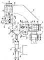
- 1 is a view for explaining the tool carrier of the conventional automatic tool changer.
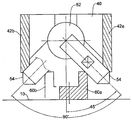
- FIG. 2 is a cross-sectional view taken along the line A-A of FIG.
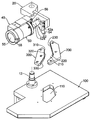
- 3 and 4 are exploded perspective view for explaining the tool carrier of the automatic tool changer according to an embodiment of the present invention.
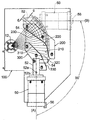
- Figure 5 is a plan view for explaining the action of the tool carrier of the automatic tool changer according to an embodiment of the present invention.
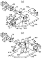
- FIG. 6 is a view for explaining the operation of the tool carrier of the automatic tool changer according to an embodiment of the present invention, (a) is a state in which the tool pocket unit is in the initial position, (b) is a tool pocket unit It is in the destination position.
- 60a, 60b first and second pin guide units 100: base plate
- first and second preceding sections 220, 320 first and second intermediate sections
- first and second trailing sections 400, 402 first and second brackets
- 3 and 4 are exploded perspective views for explaining the tool carrier of the automatic tool changer according to an embodiment of the present invention.
- the interference preventing hole 110 is formed in the base plate 100, and the first and second cam blocks 200 are moved along the path where the pin 54 of the carrier unit 40 moves. 300 is installed spaced apart.
- the above-mentioned first cam block 200 cams with the pin 54 of the pocket unit 50 when the carrier unit 40 is moved from the origin position A toward the target position B
- the above-mentioned second cam block 200 cams with the pin 54 of the pocket unit 50 when the carrier unit 40 is moved from the target position B toward the origin position A.
- first and second cam blocks 200 and 300 may contact the first and second preceding sections 210 and 310 and the pin 54 to start contact with the pin 54. It includes a second trailing section 230, 330.
- first and second preceding sections 210 and 310 and the first and second trailing sections 230 and 330 described above may have a linear shape
- first and second intermediate sections 220 described above. 320 may have a curvature shape
- first and second cam blocks 200 and 300 may be provided as a curved surface as a whole, as described above, some sections (first and second preceding sections) may be provided. Providing the 210 and 310 and the first and second trailing sections 230 and 330 in a linear shape, the first and second cam blocks 200 and 300 can be easily manufactured, and the manufacturing cost can be lowered. As a result, the rotation speed of the pocket unit 50 described above may be substantially maintained.
- first and second preceding sections 210 and 310 and the first and second trailing sections 230 and 330 described above may have different distances from the center of the sensor shaft 12.
- first and second trailing sections 230 and 330 are smaller than the distance change c from the center of the sensor shaft 12 of the first and second leading sections 210 and 310.
- the distance change d from the center of the sensor shaft 12 may be greater.
- first and second leading sections 210 and 310 rotate at a moderate speed while the pocket unit 50 rotates while the first and second cam blocks 200 and 300 and the pin 54 cam.
- the pocket unit 50 may be further moved while the first and second cam blocks 200 and 300 and the pin 54 cam. Is to rotate at high speed.
- first and second intermediate sections 220 and 320 between the first and second preceding sections 210 and 310 and the first and second trailing sections 230 and 330 described above, respectively. This may be further formed, and the rotation speed of the pocket unit 50 is uniformly maintained in the first and second intermediate sections 220 and 320.
- first and second cam blocks 200 and 300 described above are provided in separate configurations, but are not limited thereto, and the first cam block 200 and the second cam block 300 described above may be one. It may be provided in the configuration of this has the advantage that the installation and handling of the cam block is convenient.
- the first and second carrier detection units 16a and 16b described above detect whether the carrier unit 40 is normally moved, and the tool detection unit 410 described above determines whether the tool T is present. By detecting, it is detected whether the tool T is not detached.
- Figure 5 is a plan view for explaining the action of the tool carrier of the automatic tool changer according to an embodiment of the present invention
- Figure 6 is the action of the tool carrier of the automatic tool changer according to an embodiment of the present invention
- A is a state in which a tool pocket unit is in an initial position
- (b) is a state in which a tool pocket unit is in a target position.
- the carrier unit 40 pivots about the center shaft 12 in the origin position A and the target position B. As shown in FIG.
- the actuator 30 is in a state in which the rod is retracted and pulling the swing unit 20, and thus the carrier unit 40 is in the home position A. Will be.
- the rotation speed of the pocket unit 50 is generally maintained uniformly.
- the pin 54 rotates the pocket unit 50 while passing through the second leading section 310 and the second trailing section 330 of the second cam block 300, and the rotating speed of the pocket unit 50. Is uniformly maintained so that the tool T housed in the pocket unit 50 is stabilized without being impacted, thereby preventing the tool T from being randomly dislodged when moving while changing the phase of the tool T. do.
- the tool carrier of the automatic tool changer according to the invention can be used to move the tool while rotating it.
Landscapes
- Engineering & Computer Science (AREA)
- Mechanical Engineering (AREA)
- Automatic Tool Replacement In Machine Tools (AREA)
Abstract
본 발명은 자동공구교환장치의 툴 캐리어에 관한 것이다. 본 발명에 따른 자동공구교환장치의 툴 캐리어는, 센터 샤프트(12)가 설치된 베이스 플레이트(100), 센터 샤프트(12)에 설치되어 센터 샤프트(12)를 중심으로 선회되는 캐리어 유닛(40), 캐리어 유닛(40)에 자전되도록 설치되고 핀(54)이 외측으로 돌출되게 설치되는 자전되는 포켓 유닛(50), 베이스 플레이트(100)에 설치되고 핀(54)과 캠 작용하여 캐리어 유닛(40)이 초기위치(A)에서 목적위치(B)로 선회할 때에 포켓 유닛(50)을 자전시키도록 하는 제1 캠 블록(200) 및 베이스 플레이트(100)에 설치되고 핀(54)과 캠 작용하여 캐리어 유닛(40)이 목적위치(B)에서 초기 위치(A)로 선회할 때에 포켓 유닛(50)을 자전시키도록 하는 제2 캠 블록(300)을 포함한다.
Description
본 발명은 자동공구교환장치의 툴 캐리어에 관한 것으로, 더욱 상세하게는 툴 매거진과 자동공구교환장치의 사이에 배치되어 공구를 옮기도록 하는 자동공구교환장치의 툴 캐리어에 관한 것이다.
일반적으로 수치제어 공작기계에는 수많은 공구를 수납하고 있고, 특정한 공구를 호출하여 절삭가공을 실시하고, 사용 완료된 공구는 다시 수납하며, 이때 공구는 툴 매거진에 수납되고, 툴 매거진과 스핀들 간에는 자동공구교환장치(ATC)에 의해 공구를 옮긴다.
한편, 툴 매거진의 툴 포켓과 스핀들에는 키 블록이 배치되어 있고, 모든 공구에는 상술한 키 블록을 수납하는 키 홈이 형성되어 있으며 이로써 툴 포켓 또는 스핀들에 공구가 장착될 때에 키 블록과 키 홈이 맞추어 지는 특정한 방향으로 정렬된다.
또한, 공구의 형상이 축선을 기준으로 비대칭이거나, 회전반경이 큰 대경 공구의 경우 툴 매거진에 수납이 원활하지 못할 수 있고, 다른 기구 구조물과 간섭이 발생할 수 있으므로 공구의 위상을 직각으로 돌려진 상태에서 수납된다.
다른 한편으로, 툴 포켓의 키 블록과 스핀들의 키 블록은 위상이 직각을 이루는 경우가 있고, 이러한 경우에는 일반적인 자동공구교환장치로 공구교환을 이룰 수 없으므로 공구의 위상을 돌리도록 하는 툴 캐리어를 이용하게 된다.
종래의 툴 캐리어는 첨부도면 도 1 및 도 2를 참조하여 설명한다.
베이스 플레이트(10)의 한쪽에 센터 샤프트(12)가 배치되고, 센터 샤프트(12)에는 스윙 유닛(20)이 회전가능하게 설치되며, 스윙 유닛(20)의 한쪽에는 링크(32)를 매개로 액추에이터(30)가 연결되고, 스윙 유닛(20)의 다른 한쪽에는 캐리어 유닛(40)이 설치된다.
상술한 액추에이터(30)는 유압 또는 공압에 의해 구동되어 로드(31)가 확장/축소되는 것이고, 로드(31)의 단부에 상술한 링크(32)가 연결된 것이며, 액추에이터(30)는 공작기계 프레임(36)의 한쪽에 축핀(34)으로 설치되어 축핀(34)을 중심으로 액추에이터(30)의 자세가 회전 유동될 수 있도록 구성된다.
한편, 상술한 액추에이터(30)의 구동에 의해 상술한 스윙 유닛(20)이 선회하고, 스윙 유닛(20)의 선회구간은 캐리어 유닛(40)의 원점 위치(A)에서 캐리어 유닛(40)의 목적 위치(B)까지이다.
상술한 캐리어 유닛(40)은 캐리어 바디(44)의 내측에 툴 포켓 유닛(50)이 자전가능하게 구비되고 상술한 툴 포켓 유닛(50)의 회전축은 상술한 스윙 유닛(20)의 회전축과 직교하는 방향이다.
한편, 상술한 툴 포켓 유닛(50)은 내측에 핀 샤프트(52)가 상술한 캐리어 바디(44)의 내부에서 회전가능하게 배치되고, 핀 샤프트(52)의 한쪽에는 핀(54)이 돌출되게 설치된다.
또한, 상술한 핀 샤프트(52)에는 제1, 제2 정렬 홈(52a)(52b)이 형성되고, 제1, 제2 정렬 홈(52a)(52b)은 핀 샤프트(52)의 중심을 기준으로 90도 각도를 이루며, 캐리어 바디(44)의 한쪽에는 볼 스토퍼(58)가 구비되어 있으며 볼 스토퍼(58)는 상술한 제1 정렬 홈(52a) 또는 제2 정렬 홈(52b)에 삽입되어 툴 포켓 유닛(50)의 자전이 완료되면 툴 포켓 유닛(50)이 임의로 유동되는 것을 방지하게 된다.
또한, 툴 포켓 유닛(50)의 전방에는 공구(T)가 수납되도록 툴 포켓(55)이 형성되고, 툴 포켓(55)의 한쪽에는 키 블록(56)이 배치된다.
즉, 상술한 툴 포켓(55)에 공구(T)가 수납되었을 때에 공구(T)에 형성된 키 홈과 상술한 키 블록(56)이 맞춰져 공구(T)가 항상 특정한 위상으로 정렬되는 것이다.
한편, 상술한 베이스 플레이트(10)의 상측에는 제1 핀 가이드 유닛(60a)과 제2 핀 가이드 유닛(60b)이 설치되는데, 제1 핀 가이드 유닛(60a)은 캐리어 유닛(40)이 툴 매거진 쪽으로 이동이 완료된 위치에 설치되고, 제2 핀 가이드 유닛(60b)은 캐리어 유닛(40)이 스핀들 쪽으로 이동이 완료된 위치에 설치된다.
또한, 상술한 제1, 제2 핀 가이드 유닛(60a)(60b)은 도 2에 나타낸 바와 같이, 핀(54)과 접촉하게 된다.
따라서 툴 캐리어(40)가 원점 위치(A)로 복귀하도록 선회하면 어느 순간에 핀(54)은 제1 핀 가이드 유닛(60a)과 닿고, 툴 캐리어(40)가 좀 더 회전 진행되면 핀(54)은 핀 샤프트(52)를 회전시켜 툴 포켓 유닛(50)의 방향을 돌리게 된다.
반대로 툴 캐리어(40)가 목적 위치(B)로 선회하면 어느 순간에 핀(54)은 제2 핀 가이드 유닛(60b)과 닿고, 툴 캐리어(40)가 좀 더 회전 진행되면 핀(54)은 핀 샤프트(52)를 회전시켜 툴 포켓 유닛(50)의 방향을 돌리게 된다.
즉, 상술한 툴 포켓 유닛(50)은 툴 캐리어(40)가 원점위치(A) 또는 목적 위치(B) 중에 어느 위치에 있느냐에 따라 포켓 유닛(50)과 공구(T)의 위상이 변화된다.
그러나 상술한 종래의 툴 캐리어는 다음과 같은 문제점이 지적된다.
공구(T)가 툴 포켓 유닛(50)에 수납된 상태에서 원점위치(A) 또는 목적위치(B)를 왕복하게 되는데 목적하는 곳에 도착하기 직전에 핀(54)과 제1, 제2 핀 가이드 유닛(60a)(60b)이 맞닿는 순간부터 공구(T)가 자전하여 공구(T)의 위상이 변화하게 된다.
그런데 상술한 바와 같이 핀(54)과 제1, 제2 핀 가이드 유닛(60a)(60b)이 닿는 순간에 충격이 발생하고 이러한 충격으로 인하여 툴 포켓 유닛(50)에서 공구(T)가 이탈되는 문제점이 있다.
특히 특수 목적으로 제공되는 공구(T)는 회전축을 중심으로 비대칭으로 형성되므로 공구(T)의 무게중심이 어느 한쪽으로 편중되고, 이러한 공구(T)가 툴 포켓 유닛(50)에 수납되었을 때에 불안정한 상태일 수 있다.
또한, 공구(T)의 직경이 큰 대경 공구도 무게 중심이 외측으로 편중되므로 이러한 공구(T)가 툴 포켓 유닛(50)에 수납되었을 때에 불안정한 상태일 수 있다.
상술한 바와 같이, 무게 중심이 어느 한쪽으로 편중된 특수한 공구(T)의 경우에는 원점위치(A) 또는 목적위치(B)에 도달이 완료될 시점에 핀(54)과 제1, 제2 핀 가이드 유닛(60a)(60b)이 부딪히는 충격에 의해 직후에 공구(T)가 툴 포켓(55)에서 이탈되는 문제점이 있다.
따라서 본 발명이 이루고자 하는 기술적 과제는 공구를 이동하는 도중에 자전이 이루어지도록 하여 공구가 이동될 때에 툴 포켓 유닛에서 공구가 이탈되는 것을 방지하도록 하는 자동공구교환장치의 툴 캐리어를 제공하는데 그 목적이 있다.
본 발명이 이루고자 하는 기술적 과제는 이상에서 언급한 기술적 과제로 제한되지 않으며, 언급되지 않은 또 다른 기술적 과제는 아래의 기재로부터 본 발명이 속하는 기술분야에서 통상의 지식을 가진 자에게 명확하게 이해될 수 있을 것이다.
상기 기술적 과제를 달성하기 위한 본 발명에 따른 자동공구교환장치의 툴 캐리어는, 센터 샤프트가 설치된 베이스 플레이트; 상기 센터 샤프트에 설치되어 상기 센터 샤프트를 중심으로 선회되는 캐리어 유닛; 상기 캐리어 유닛에 자전되도록 설치되고 핀이 외측으로 돌출되게 설치되는 자전되는 포켓 유닛; 상기 베이스 플레이트에 설치되고 상기 핀과 캠 작용하여 상기 캐리어 유닛이 초기 위치에서 목적 위치로 선회할 때에 상기 포켓 유닛을 자전시키도록 하는 제1 캠 블록; 및 상기 베이스 플레이트에 설치되고 상기 핀과 캠 작용하여 상기 캐리어 유닛이 목적 위치에서 초기 위치로 선회할 때에 상기 포켓 유닛을 자전시키도록 하는 제2 캠 블록;을 포함한다.
또한, 상기 제1, 제2 캠 블록은, 상기 핀과 캠 작용을 할 때에 상기 포켓 유닛의 자전속도를 균등하게 선행 진행하도록 하는 제1, 제2 선행 구간; 상기 핀과 캠 작용을 할 때에 상기 포켓 유닛의 자전속도를 균등하게 후행 진행하도록 하는 제1, 제2 후행 구간; 및 상기 제1, 제2 선행 구간과 상기 제1, 제2 후행 구간의 사이에 배치되어 상기 포켓 유닛의 자전속도를 균등하게 진행되도록 하는 제1, 제2 중간구간;을 포함할 수 있다.
또한, 상기 제1, 제2 선행 구간과 상기 제1, 제2 후행 구간은 선형 형상이고, 상기 제1, 제2 중간구간은 곡률 형상인 것일 수 있다.
기타 실시예들의 구체적인 사항들은 상세한 설명 및 도면들에 포함되어 있다.
상기한 바와 같이 이루어진 본 발명에 따른 자동공구교환장치의 툴 캐리어는 툴 포켓 유닛이 초기위치와 목적위치 간에 이동하는 동안에 자전하므로 종래에서처럼 어느 특정한 순간에 자전하도록 하는 충격을 받지 않으므로 툴 포켓 유닛에 수납된 공구가 안정되게 수납된 상태를 유지할 수 있는 것이다.
도 1은 종래의 자동공구교환장치의 툴 캐리어를 설명하기 위한 도면이다.
도 2는 도 1의 A-A선 단면도면이다.
도 3 및 도 4는 본 발명의 일 실시예에 따른 자동공구교환장치의 툴 캐리어를 설명하기 위한 분해사시도면이다.
도 5는 본 발명의 일 실시예에 따른 자동공구교환장치의 툴 캐리어의 작용을 설명하기 위한 평면도면이다.
도 6은 본 발명의 일 실시예에 따른 자동공구교환장치의 툴 캐리어의 작용을 설명하기 위한 도면으로서, (a)는 툴 포켓 유닛이 초기위치에 있는 상태이고, (b)는 툴 포켓 유닛이 목적 위치에 있는 상태이다.
<도면의 주요 참조 부호에 대한 설명>
10: 베이스 플레이트 12: 센터 샤프트
14a, 14b: 제1, 제2 스토퍼 유닛 16a, 16b: 제1, 제2 캐리어 검출 유닛
20: 스윙 유닛 30: 액추에이터
32: 링크 40: 캐리어 유닛
42a, 42b: 제1, 제2 가이드 유닛 44: 캐리어 바디
50: 포켓 유닛 52: 핀 샤프트
52a, 52b : 제1, 제2 정렬 홈 54: 핀
56: 키 블록 58: 볼 스토퍼
60a, 60b: 제1, 제2 핀 가이드 유닛 100: 베이스 플레이트
110: 홀 200, 300: 제1, 제2 캠 블록
210, 310: 제1, 제2 선행 구간 220, 320: 제1, 제2 중간 구간
230, 330: 제1, 제2 후행 구간 400, 402: 제1, 제2 브래킷
410: 툴 검출 유닛
본 발명의 이점 및 특징, 그리고 그것들을 달성하는 방법은 첨부되는 도면과 함께 상세하게 후술되어 있는 실시예를 참조하면 명확해질 것이다.
명세서 전체에 걸쳐 동일 참조 부호는 동일 구성요소를 지칭하고, 종래기술과 동일한 구성요소에 대하여 동일한 부호를 부여하고 그에 따른 상세한 설명은 생략한다.
이하, 도 3 및 도 4를 참조하여 본 발명의 일 실시예에 따른 자동공구교환장치의 툴 캐리어에 대해서 설명한다.
첨부도면 도 3 및 도 4는 본 발명의 일 실시예에 따른 자동공구교환장치의 툴 캐리어를 설명하기 위한 분해사시도면이다.
도 3 및 도 4에 나타낸 바와 같이, 베이스 플레이트(100)에 간섭 방지용 홀(110)이 형성되고, 캐리어 유닛(40)의 핀(54)이 이동하는 경로에 제1, 제2 캠 블록(200)(300)이 이격되어 설치된다.
상술한 제1 캠 블록(200)은 캐리어 유닛(40)이 원점위치(A)에서 목적위치(B) 쪽으로 이동될 때에 포켓 유닛(50)의 핀(54)과 캠 작용하고, 상술한 제2 캠 블록(300)은 캐리어 유닛(40)이 목적위치(B)에서 원점위치(A) 쪽으로 이동될 때에 포켓 유닛(50)의 핀(54)과 캠 작용하는 것이다.
한편, 제1, 제2 캠 블록(200)(300)은 핀(54)과 접촉을 시작하는 제1, 제2 선행구간(210)(310)과 핀(54)과 접촉이 끝나는 제1, 제2 후행 구간(230)(330)을 포함하여 구성된다.
또한, 상술한 제1, 제2 선행 구간(210)(310)과 상기 제1, 제2 후행 구간(230)(330)은 선형 형상일 수 있고, 상술한 제1, 제2 중간구간(220)(320)은 곡률 형상일 수 있다.
즉, 상술한 제1, 제2 캠 블록(200)(300)에서 핀(54)과 접촉되는 면은 전체적으로 곡면으로 제공될 수도 있지만, 상술한 바와 같이, 일부 구간(제1, 제2 선행 구간(210)(310)과 상기 제1, 제2 후행 구간(230)(330))을 선형 형상으로 제공함으로써 제1, 제2 캠 블록(200)(300)의 제조가 쉽고 제조원가를 낮출 수 있으며, 상술한 포켓 유닛(50)의 자전속도가 대체로 균등하게 유지될 수 있다.
다른 한편으로, 상술한 제1, 제2 선행구간(210)(310)과 상술한 제1, 제2 후행 구간(230)(330)은 센서 샤프트(12)의 중심으로부터의 거리 변화가 다를 수 있고, 좀 더 상세하게는, 제1, 제2 선행구간(210)(310)의 센서 샤프트(12)의 중심으로부터의 거리 변화(c)보다 제1, 제2 후행 구간(230)(330)의 센서 샤프트(12)의 중심으로부터의 거리 변화(d)가 더 클 수 있다.
따라서 제1, 제2 선행구간(210)(310)은 제1, 제2 캠 블록(200)(300)과 핀(54)이 캠 작용을 하는 동안에 포켓 유닛(50)이 완만한 속도로 회전을 하도록 하고, 제1, 제2 후행 구간(230)(330)은 제1, 제2 캠 블록(200)(300)과 핀(54)이 캠 작용을 하는 동안에 포켓 유닛(50)이 좀 더 빠른 속도로 회전하도록 하는 것이다.
한편, 상술한 제1, 제2 선행 구간(210)(310)과 상술한 제1, 제2 후행구간(230)(330)의 사이에 각각 제1, 제2 중간 구간(220)(320)이 더 형성될 수 있고, 제1, 제2 중간 구간(220)(320)에서 포켓 유닛(50)의 자전속도가 균등하게 유지된다.
한편, 상술한 제1, 제2 캠 블록(200)(300)은 베이스 플레이트(100)와 별개로 제공되고 제1, 제2 캠 블록(200)(300)이 베이스 플레이트(100)에 설치되는 위치가 미세조정이 가능하며 이로써 핀(54)과의 캠 작용이 더욱 원활하게 이루어질 수 있다.
다른 한편으로, 상술한 제1, 제2 캠 블록(200)(300)은 별개의 구성으로 제공되지만 이에 한정되는 것은 아니며 상술한 제1 캠 블록(200)과 제2 캠 블록(300)은 하나의 구성으로 제공될 수도 있고 이로써 캠 블록의 설치 및 취급이 편리해지는 이점이 있다.
또 다른 한편으로, 베이스 플레이트(100)의 한쪽에는 캐리어 유닛(40)이 멈추어 정렬되도록 하는 제1, 제2 스토퍼 유닛(14a)(14b)이 설치되고, 상술한 제1, 제2 스토퍼 유닛(14a)(14b)에는 상술한 캐리어 유닛(40)을 검출하도록 하는 제1, 제2 캐리어 검출 유닛(16a)(16b)이 각각 설치될 수 있다.
또 다른 한편으로, 상술한 제1, 제2 스토퍼 유닛(14a)(14b)의 상측에는 각각 제1, 제2 브래킷(400)(402)이 더 설치될 수 있고, 상술한 제1, 제2 브래킷(400)(402)에는 공구(T)를 검출하도록 하는 공구 검출 유닛(410)이 더 설치될 수 있다.
즉, 상술한 제1, 제2 캐리어 검출 유닛(16a)(16b)은 캐리어 유닛(40)이 정상적으로 이동이 완료되었는지 검출하고, 상술한 공구 검출 유닛(410)은 공구(T)의 존재 유무를 검출하여 공구(T)가 이탈되지 않았는지 검출하게 된다.
이하, 도 5 및 도 6을 참조하여 본 발명의 일 실시예에 따른 자동공구교환장치의 툴 캐리어의 작용에 대해서 설명한다.
첨부도면 도 5는 본 발명의 일 실시예에 따른 자동공구교환장치의 툴 캐리어의 작용을 설명하기 위한 평면도면이고, 도 6은 본 발명의 일 실시예에 따른 자동공구교환장치의 툴 캐리어의 작용을 설명하기 위한 도면으로서, (a)는 툴 포켓 유닛이 초기 위치에 있는 상태이고, (b)는 툴 포켓 유닛이 목적 위치에 있는 상태이다.
액추에이터 유닛(30)이 신장 또는 수축작용을 하면 캐리어 유닛(40)은 센터 샤프트(12)를 중심으로 원점위치(A)와 목적위치(B)의 범위에서 선회하게 된다.
먼저, 캐리어 유닛(40)이 초기위치(A)에 있을 때에는 액추에이터(30)는 로드가 수축된 상태로서 스윙 유닛(20)을 당기고 있는 상태이고 이로서 캐리어 유닛(40)은 원점위치(A)에 있게 된다.
또한, 상술한 캐리어 유닛(40)에는 포켓 유닛(50)이 배치되는데 포켓 유닛(50)의 위상을 살펴보면 키 블록(56)이 방위각으로 3시 방향에 위치한다.
이후 포켓 유닛(50)에 공구(T)가 수납되고 액추에이터(30)가 작용하면 스윙 유닛(20) 및 캐리어 유닛(40)은 센서 샤프트(12)를 중심으로 선회하고 아울러 포켓 유닛(50)의 핀(54)은 제1 캠 블록(200)과 캠 작용이 시작된다.
캐리어 유닛(40)의 회전이 진행되는 동안에 포켓 유닛(50)의 핀(54)은 제1 캠 블록(200)과의 캠 작용에 의해 포켓 유닛(50)이 자전하게 된다.
특히, 핀(54)이 제1 선행 구간(210)과 제1 후행 구간(230)을 통과하는 동안에 포켓 유닛(50)의 자전속도는 전반적으로 균등하게 유지된다.
이후, 도 6의 [b]에 나타낸 바와 같이, 캐리어 유닛(40)이 초기위치(A)에서 목적위치(B)로 선회가 완료되면 포켓 유닛(50)의 위상은 직각으로 자전되어 있고, 키 블록(56)을 살펴보면 방위가 6시 방향임을 알 수 있다.
액추에이터(30)가 역으로 작용하면 스윙 유닛(20) 및 캐리어 유닛(40)은 목적위치(B)에서 초기위치(A)로 복귀하게 되고, 이러한 복귀 과정에서 핀(54)은 제2 캠 블록(300)과 캠 작용한다.
즉, 핀(54)은 제2 캠 블록(300)의 제2 선행구간(310)과 제2 후행구간(330)을 통과하면서 포켓 유닛(50)을 자전시키고, 포켓 유닛(50)의 자전속도는 균등하게 유지되어 포켓 유닛(50)에 수납된 공구(T)가 충격을 받지 않고 안정되며, 이로써 공구(T)의 위상을 바꾸면서 이동시킬 때에 공구(T)가 임의로 이탈되는 것을 방지할 수 있게 된다.
이상 첨부된 도면을 참조하여 본 발명의 실시예를 설명하였지만, 본 발명이 속하는 기술분야의 당업자는 본 발명이 그 기술적 사상이나 필수적 특징을 변경하지 않고 다른 구체적인 형태로 실시될 수 있다는 것을 이해할 수 있을 것이다.
그러므로 이상에서 기술한 실시예는 모든 면에서 예시적인 것이며 한정적인 것이 아닌 것으로서 이해되어야 하고, 본 발명의 범위는 상기 상세한 설명은 후술하는 특허청구범위에 의하여 나타내어지며, 특허청구범위의 의미 및 범위 그리고 그 등가개념으로부터 도출되는 모든 변경 또는 변형된 형태가 본 발명의 범위에 포함되는 것으로 해석되어야 한다.
본 발명에 따른 자동공구교환장치의 툴 캐리어는 공구의 위상을 돌리면서 옮기도록 하는 데에 이용될 수 있다.
Claims (3)
- 센터 샤프트(12)가 설치된 베이스 플레이트(100);상기 센터 샤프트(12)에 설치되어 상기 센터 샤프트(12)를 중심으로 선회되는 캐리어 유닛(40);상기 캐리어 유닛(40)에 자전되도록 설치되고 핀(54)이 외측으로 돌출되게 설치되는 자전되는 포켓 유닛(50);상기 베이스 플레이트(100)에 설치되고 상기 핀(54)과 캠 작용하여 상기 캐리어 유닛(40)이 초기 위치(A)에서 목적 위치(B)로 선회할 때에 상기 포켓 유닛(50)을 자전시키도록 하는 제1 캠 블록(200); 및상기 베이스 플레이트(100)에 설치되고 상기 핀(54)과 캠 작용하여 상기 캐리어 유닛(40)이 목적 위치(B)에서 초기 위치(A)로 선회할 때에 상기 포켓 유닛(50)을 자전시키도록 하는 제2 캠 블록(300);을 포함하는 자동공구교환장치의 툴 캐리어.
- 제 1항에 있어서,상기 제1, 제2 캠 블록(200)(300)은,상기 핀(54)과 캠 작용을 할 때에 상기 포켓 유닛(50)의 자전속도를 균등하게 선행 진행하도록 하는 제1, 제2 선행 구간(210)(310);상기 핀(54)과 캠 작용을 할 때에 상기 포켓 유닛(50)의 자전속도를 균등하게 후행 진행하도록 하는 제1, 제2 후행 구간(230)(330); 및상기 제1, 제2 선행 구간(210)(310)과 상기 제1, 제2 후행 구간(230)(330)의 사이에 배치되어 상기 포켓 유닛(50)의 자전속도를 균등하게 진행되도록 하는 제1, 제2 중간구간(220)(320);을 포함하는 자동공구교환장치의 툴 캐리어.
- 제 2항에 있어서,상기 제1, 제2 선행 구간(210)(310)과 상기 제1, 제2 후행 구간(230)(330)은 선형 형상이고, 상기 제1, 제2 중간구간(220)(320)은 곡률 형상인 것을 특징으로 하는 자동공구교환장치의 툴 캐리어.
Priority Applications (2)
| Application Number | Priority Date | Filing Date | Title |
|---|---|---|---|
| US13/880,123 US9352433B2 (en) | 2010-10-18 | 2011-10-18 | Tool carrier for an automatic tool changer |
| CN201180050061.3A CN103167929B (zh) | 2010-10-18 | 2011-10-18 | 自动工具交换装置的工具托架 |
Applications Claiming Priority (2)
| Application Number | Priority Date | Filing Date | Title |
|---|---|---|---|
| KR10-2010-0101179 | 2010-10-18 | ||
| KR1020100101179A KR101761913B1 (ko) | 2010-10-18 | 2010-10-18 | 자동공구교환장치의 툴 캐리어 |
Publications (2)
| Publication Number | Publication Date |
|---|---|
| WO2012053793A2 true WO2012053793A2 (ko) | 2012-04-26 |
| WO2012053793A3 WO2012053793A3 (ko) | 2012-06-28 |
Family
ID=45975712
Family Applications (1)
| Application Number | Title | Priority Date | Filing Date |
|---|---|---|---|
| PCT/KR2011/007731 Ceased WO2012053793A2 (ko) | 2010-10-18 | 2011-10-18 | 자동공구교환장치의 툴 캐리어 |
Country Status (4)
| Country | Link |
|---|---|
| US (1) | US9352433B2 (ko) |
| KR (1) | KR101761913B1 (ko) |
| CN (1) | CN103167929B (ko) |
| WO (1) | WO2012053793A2 (ko) |
Families Citing this family (1)
| Publication number | Priority date | Publication date | Assignee | Title |
|---|---|---|---|---|
| TWI661896B (zh) * | 2018-11-07 | 2019-06-11 | 臻賞工業股份有限公司 | 工具刀庫之換刀裝置 |
Family Cites Families (15)
| Publication number | Priority date | Publication date | Assignee | Title |
|---|---|---|---|---|
| BG18460A1 (ko) | 1973-02-24 | 1975-02-25 | ||
| US3990140A (en) | 1974-11-20 | 1976-11-09 | Houdaille Industries, Inc. | Vertical tool changer to adapter holding mechanism |
| JPS5292175A (en) * | 1976-01-29 | 1977-08-03 | Toyoda Mach Works Ltd | Machine tool which is provided with automatic tool changing device |
| AR225485A1 (es) * | 1980-02-08 | 1982-03-31 | Oerlikon Buehrle Ag | Una maquina-herramienta |
| US4520550A (en) * | 1983-05-27 | 1985-06-04 | Automated Robotic Systems, Inc. | Robot tool changer |
| JPS63267136A (ja) * | 1987-04-25 | 1988-11-04 | Brother Ind Ltd | 工作機械の自動工具交換装置 |
| DE3831869A1 (de) * | 1988-09-20 | 1990-03-29 | Chiron Werke Gmbh | Werkzeugmaschine |
| JP3201804B2 (ja) | 1991-12-13 | 2001-08-27 | 株式会社森精機製作所 | 自動工具交換装置のロック構造 |
| KR950005791Y1 (ko) | 1992-12-31 | 1995-07-21 | 이경훈 | 툴 포트 선회장치 |
| CN2214260Y (zh) | 1994-11-10 | 1995-12-06 | 财团法人工业技术研究院 | 综合加工机床的刀具库倒刀装置 |
| US5554087A (en) * | 1994-11-15 | 1996-09-10 | Industrial Technology Research Institute | Tool pivoting mechanism of a tool magazine |
| JP3345618B2 (ja) | 1996-09-24 | 2002-11-18 | クライムプロダクツ株式会社 | ツールチェンジャー |
| DE10012665C2 (de) * | 2000-03-15 | 2003-10-09 | Deckel Maho Seebach Gmbh | Werkzeugwechselvorrichtung für eine Werkzeugmaschine |
| JP3992484B2 (ja) | 2001-12-06 | 2007-10-17 | 株式会社三共製作所 | 自動工具交換装置 |
| KR100473553B1 (ko) | 2002-11-23 | 2005-03-08 | 대우종합기계 주식회사 | 머시닝센터의 자동공구 교환장치 |
-
2010
- 2010-10-18 KR KR1020100101179A patent/KR101761913B1/ko active Active
-
2011
- 2011-10-18 WO PCT/KR2011/007731 patent/WO2012053793A2/ko not_active Ceased
- 2011-10-18 CN CN201180050061.3A patent/CN103167929B/zh active Active
- 2011-10-18 US US13/880,123 patent/US9352433B2/en active Active
Also Published As
| Publication number | Publication date |
|---|---|
| CN103167929A (zh) | 2013-06-19 |
| KR20120039781A (ko) | 2012-04-26 |
| US20130217553A1 (en) | 2013-08-22 |
| US9352433B2 (en) | 2016-05-31 |
| WO2012053793A3 (ko) | 2012-06-28 |
| CN103167929B (zh) | 2015-09-16 |
| KR101761913B1 (ko) | 2017-08-07 |
Similar Documents
| Publication | Publication Date | Title |
|---|---|---|
| JPH01120032A (ja) | ウェーハの位置検出装置 | |
| WO2012081860A2 (ko) | 툴 매거진의 툴 캐리어 유닛 | |
| US20120220437A1 (en) | Tool magazine and machining center | |
| WO2012053793A2 (ko) | 자동공구교환장치의 툴 캐리어 | |
| WO2021215892A1 (ko) | 파우치형 이차 전지용 정렬 장치 | |
| US4443928A (en) | Multiple-spindle tool changer | |
| WO2023246049A1 (zh) | 惯量调节机构及电机 | |
| CN210115724U (zh) | 扩展刀库 | |
| JP2002018753A (ja) | ウエハーハンドリングロボットのティーチング装置および方法 | |
| CN112059621A (zh) | 一种配套有刀具库的钻攻一体机 | |
| US10150191B2 (en) | Tool changer | |
| CN219497756U (zh) | 一种对中装置及电池片输送线 | |
| CN217486319U (zh) | 惯量调节机构及电机 | |
| CN220516231U (zh) | 一种刀库断刀检测机构 | |
| CN217114001U (zh) | 一种标记绝缘帽 | |
| WO2020226268A1 (ko) | 확장 수납구조를 갖는 공작기계용 자동공구교환장치와, 이를 이용한 공구의 공급방법 | |
| EP1080831B1 (en) | Tool-exchange apparatus for machine tools | |
| JP4357843B2 (ja) | ターンテーブルの位置決め機構 | |
| WO2021107467A1 (ko) | 공작기계 공구매거진과 주축 사이의 공구교환방법 | |
| JPH0657536U (ja) | 自動工具交換装置 | |
| CN219932099U (zh) | 一种具有限位装置的机械手及天井钻机 | |
| KR102910580B1 (ko) | 웨이퍼 파지장치 | |
| CN217345521U (zh) | 夹爪装置 | |
| CN223293676U (zh) | 一种转盘式钻杆库 | |
| JPS6354505B2 (ko) |
Legal Events
| Date | Code | Title | Description |
|---|---|---|---|
| 121 | Ep: the epo has been informed by wipo that ep was designated in this application |
Ref document number: 11834593 Country of ref document: EP Kind code of ref document: A2 |
|
| NENP | Non-entry into the national phase |
Ref country code: DE |
|
| WWE | Wipo information: entry into national phase |
Ref document number: 13880123 Country of ref document: US |
|
| 122 | Ep: pct application non-entry in european phase |
Ref document number: 11834593 Country of ref document: EP Kind code of ref document: A2 |