WO2012053584A1 - 燃料フィルター用ケース及び燃料フィルター装置 - Google Patents
燃料フィルター用ケース及び燃料フィルター装置 Download PDFInfo
- Publication number
- WO2012053584A1 WO2012053584A1 PCT/JP2011/074141 JP2011074141W WO2012053584A1 WO 2012053584 A1 WO2012053584 A1 WO 2012053584A1 JP 2011074141 W JP2011074141 W JP 2011074141W WO 2012053584 A1 WO2012053584 A1 WO 2012053584A1
- Authority
- WO
- WIPO (PCT)
- Prior art keywords
- fuel
- fuel filter
- case
- filter
- suction port
- Prior art date
- Legal status (The legal status is an assumption and is not a legal conclusion. Google has not performed a legal analysis and makes no representation as to the accuracy of the status listed.)
- Ceased
Links
Images





Classifications
-
- B—PERFORMING OPERATIONS; TRANSPORTING
- B01—PHYSICAL OR CHEMICAL PROCESSES OR APPARATUS IN GENERAL
- B01D—SEPARATION
- B01D35/00—Filtering devices having features not specifically covered by groups B01D24/00 - B01D33/00, or for applications not specifically covered by groups B01D24/00 - B01D33/00; Auxiliary devices for filtration; Filter housing constructions
- B01D35/02—Filters adapted for location in special places, e.g. pipe-lines, pumps, stop-cocks
- B01D35/027—Filters adapted for location in special places, e.g. pipe-lines, pumps, stop-cocks rigidly mounted in or on tanks or reservoirs
- B01D35/0273—Filtering elements with a horizontal or inclined rotation or symmetry axis submerged in tanks or reservoirs
-
- F—MECHANICAL ENGINEERING; LIGHTING; HEATING; WEAPONS; BLASTING
- F02—COMBUSTION ENGINES; HOT-GAS OR COMBUSTION-PRODUCT ENGINE PLANTS
- F02M—SUPPLYING COMBUSTION ENGINES IN GENERAL WITH COMBUSTIBLE MIXTURES OR CONSTITUENTS THEREOF
- F02M37/00—Apparatus or systems for feeding liquid fuel from storage containers to carburettors or fuel-injection apparatus; Arrangements for purifying liquid fuel specially adapted for, or arranged on, internal-combustion engines
- F02M37/22—Arrangements for purifying liquid fuel specially adapted for, or arranged on, internal-combustion engines, e.g. arrangements in the feeding system
- F02M37/32—Arrangements for purifying liquid fuel specially adapted for, or arranged on, internal-combustion engines, e.g. arrangements in the feeding system characterised by filters or filter arrangements
- F02M37/44—Filters structurally associated with pumps
-
- F—MECHANICAL ENGINEERING; LIGHTING; HEATING; WEAPONS; BLASTING
- F02—COMBUSTION ENGINES; HOT-GAS OR COMBUSTION-PRODUCT ENGINE PLANTS
- F02M—SUPPLYING COMBUSTION ENGINES IN GENERAL WITH COMBUSTIBLE MIXTURES OR CONSTITUENTS THEREOF
- F02M37/00—Apparatus or systems for feeding liquid fuel from storage containers to carburettors or fuel-injection apparatus; Arrangements for purifying liquid fuel specially adapted for, or arranged on, internal-combustion engines
- F02M37/22—Arrangements for purifying liquid fuel specially adapted for, or arranged on, internal-combustion engines, e.g. arrangements in the feeding system
- F02M37/32—Arrangements for purifying liquid fuel specially adapted for, or arranged on, internal-combustion engines, e.g. arrangements in the feeding system characterised by filters or filter arrangements
- F02M37/50—Filters arranged in or on fuel tanks
Definitions
- the present invention relates to a fuel filter case used for a fuel filter for filtering fuel in a fuel tank, and a fuel filter device including a fuel filter for filtering fuel in the fuel tank.
- Fuel in a fuel tank in an automobile or a motorcycle is usually supplied to an internal combustion engine through a fuel filter device arranged in the fuel tank.
- a fuel filter device has a fuel filter suspended in a fuel tank via a fuel pump.
- a filter material sheet such as a mesh woven fabric or a non-woven fabric is used.
- a bag-like filter member formed from the above is known.
- the filter member described in Patent Document 1 has a filter material sheet that is double-folded at one fold, and a pair of sheet portions partitioned by the fold are welded at the edges to form a bag shape. Is formed.
- a frame member as a skeleton that separates the pair of sheet portions from each other is disposed inside the filter member formed in a bag shape.
- the fuel filtered in each of the pair of seat portions is supplied to the internal combustion engine through the inside of the filter member surrounded by the seat portions.
- the present invention has been made in view of the above circumstances, and an object of the present invention is to provide a fuel filter case and a fuel filter device capable of enhancing the startability of fuel supply via the fuel filter.
- the fuel filter is formed in a box shape having a storage space in which the fuel filter suspended from the fuel tank and the fuel are stored, and the fuel in the fuel tank flows into the storage space.
- a lid having a case main body having an inlet for inflow on the top surface, and a positioning portion connected to the case main body so as to cover a part of the inlet and connected to the fuel filter to be positioned on the fuel filter
- a fuel filter case comprising a body is provided.
- the gist is that the positioning portion is a clamp that is connected to a connecting pipe that is a portion joined to a fuel pump by the fuel filter.
- the positioning portion can be configured by a clamp that is connected to a joint portion that is a portion joined to the fuel pump by the fuel filter, as in this preferred embodiment.
- the case body is formed on the bottom side of the inflow port, and sucks the fuel into the housing space by suction of a fuel pump, and the suction port communicates with the housing space.
- the communication path has a labyrinth structure that suppresses the fuel in the housing space from flowing out of the suction port.
- the fuel in the housing space can be prevented from flowing out from the suction port through the communication passage, so that it is possible to improve the fuel storage property in the fuel filter case.
- the case body is formed to have a bottom wall formed with a suction port for sucking fuel into the housing space by suction of a fuel pump, and to extend from the suction port toward the top surface side.
- the gist of the present invention is to provide a cylindrical body that communicates the suction port and the accommodation space.
- the fuel can be sucked into the accommodation space through the suction port formed in the bottom wall. Therefore, even when the fuel in the fuel tank is reduced, the fuel can be sucked into the accommodation space. Further, since the suction port and the accommodation space communicate with each other via the cylinder extending toward the top surface, at least fuel corresponding to the height of the cylinder can be stored in the accommodation space.
- the gist is provided with an opening / closing mechanism that allows the lid body to rotate with respect to the case body so as to open and close the inflow port.
- the fuel filter is usually disposed in the fuel tank through an opening provided in the fuel tank.
- the fuel filter case positioned on the fuel filter is also disposed in the fuel tank through the opening.
- the lid for positioning the fuel filter case is rotatable with respect to the case main body, the orientation and position of the case main body with respect to the fuel filter can be changed.
- the relative position of the fuel filter case and the fuel filter can be changed in accordance with the shape of the opening of the fuel tank. Therefore, the application range of the fuel filter case can be greatly expanded as compared with the configuration in which the lid is fixed to the case body.
- a fuel filter device comprising a fuel filter and a fuel filter case for housing the fuel filter, wherein the fuel filter case is according to the first aspect of the present invention.
- a fuel filter device that is a case for a fuel filter.
- the liquid level of the fuel in the fuel tank also changes according to the shape of the fuel tank. .
- the relative position between the fuel level in the fuel tank and the fuel filter suspended from the fuel tank also changes.
- the fuel filter case disposed in the fuel tank accommodates the fuel filter and the fuel. Then, with the fuel filter case positioned on the fuel filter, the fuel filter case and the fuel filter are suspended from the fuel tank. Therefore, for example, even if the posture of the vehicle is inclined with respect to the horizontal direction, it is possible to maintain the relative positions of the fuel and the fuel filter in the fuel filter case. Therefore, regardless of the position of the vehicle, it is possible to immerse the fuel filter in the fuel, and thus improve the startability of the fuel supply through the fuel filter.
- the fuel filter device of the present invention it is possible to store the fuel before filtration in the fuel filter case, and to immerse the fuel filter in the fuel stored in the fuel filter case. It becomes.
- the perspective view which shows the perspective structure of a fuel filter apparatus. (A) It is a perspective view which shows the perspective structure of a fuel filter, Comprising: The figure which cuts off a part of filter member and shows the internal structure of a fuel filter, (b) Sectional drawing which shows the cross-section of the filter material sheet in a welding part. The perspective view which shows the perspective structure of a frame member. Sectional drawing which shows the cross-sectional structure of the fuel filter in the connection part vicinity.
- the top view which shows the planar structure of the case for fuel filters. Sectional drawing which shows the cross-section in the introduction part of the case for fuel filters.
- FIG. 1 is a diagram schematically showing a schematic configuration of a fuel supply device using a fuel filter device.
- the fuel supply device 10 includes a fuel tank 11 in which fuel F is stored, and a fuel pump 13 and a fuel filter device 20 disposed in the fuel tank 11.
- the fuel filter device 20 is suspended from the upper surface of the fuel tank 11 while being inclined with respect to the bottom surface of the fuel tank 11, and includes a fuel filter 21 that filters the fuel F, and a fuel filter case that houses the fuel filter 21. 22 (hereinafter simply referred to as case 22).
- case 22 hereinafter simply referred to as case 22.
- the fuel filter device 20 is suspended so that the fuel filter device 20 contacts the bottom surface of the fuel tank 11, but the fuel filter device 20 is separated from the bottom surface of the fuel tank 11. 20 may be suspended.
- the fuel filter 21 is connected to the fuel pump 13 via a connecting member 44 as a connecting pipe.
- the fuel pump 13 is connected to a supply pipe 16 fixed to the fuel tank 11 by a flange 15 that closes the carry-in port 14.
- the fuel supply device 10 filters the fuel F in the fuel tank 11 by the fuel filter device 20, and passes the filtered fuel F to the internal combustion engine 17 through the supply pipe 16. Supply.
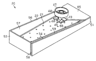
- FIG. 2 is a perspective view showing a perspective structure of the fuel filter device.
- the fuel filter device 20 includes a fuel filter 21 and a case 22 that houses the fuel filter 21 and is positioned with respect to the fuel filter 21.
- the case 22 is formed in a bottomed box shape having an opening (inlet) on the top surface, and the fuel filter 21 is accommodated in the accommodating space 57.
- the case 22 has a cover 65 connected to one of its peripheral walls, and a clamp 66 provided at the tip of the cover 65 is coupled to the connection member 44 of the fuel filter 21, thereby connecting the case 22 to the fuel filter 21.
- the case 22 is positioned.
- FIG. 3A is a perspective view showing a perspective structure of the fuel filter, and is a view showing an internal structure of the fuel filter by cutting out a part of the filter member.
- FIG.3 (b) is sectional drawing which shows the cross-section of the filter material sheet in a welding part.
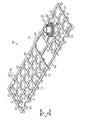
- FIG. 4 is a perspective view showing a perspective structure of the frame member.
- FIG. 5 is a sectional view showing a sectional structure of the fuel filter in the vicinity of the connecting portion.
- the fuel filter 21 includes a filter member 24 formed into a flat bag shape by sheet portions 23a and 23b facing each other, and a frame member disposed in the filter member 24. 25 and a connecting member 44 projecting to the outside of the filter member 24.
- the filter member 24 is formed of a single filter medium sheet 23 in which a plurality of sheet-like synthetic fibers are laminated.
- the filter member 24 has the above-described filter material sheet 23 that is double-folded at one fold, and the upper sheet portion 23a and the lower sheet portion 23b that are partitioned by the fold are welded at the edges of each other. Is formed into a bag shape.
- the filter medium sheet 23 of this embodiment has a nonwoven fabric 26a formed of polypropylene fibers as an innermost layer, and a plain weave mesh fabric 27 that can separate oil and water. It has as an outer layer. Between these nonwoven fabrics 26a and the mesh fabric 27, the nonwoven fabrics 26b and 26c are laminated
- the filter member 24 composed of such a filter material sheet 23
- foreign matters having a large particle diameter are captured by the layer located on the outside, and foreign matters having a small particle diameter are captured by the layer located on the inside. That is, since foreign substances having different sizes are captured by different layers, clogging in each layer can be suppressed.
- the nonwoven fabric formed by the spunbond method is used for the nonwoven fabric 26a which is the innermost layer, and the nonwoven fabric formed by the melt blown method is used for the nonwoven fabrics 26b and 26c which are intermediate layers, relatively high rigidity is obtained. Since it is given to the nonwoven fabric 26a, generation of particles from the nonwoven fabric due to rubbing between the nonwoven fabric 26a and the frame member 25 can be suppressed.
- the filter material sheet 23 is discretely provided with a plurality of welded portions 28 in which the nonwoven fabrics 26a, 26b, 26c and the mesh fabric 27 are welded by ultrasonic welding from the nonwoven fabric 26a side which is the innermost layer.
- Each of the plurality of welded portions 28 is formed in a circular hole shape on the inner surface of the filter member 24.
- the laminated nonwoven fabrics 26a, 26b, and 26c and the mesh fabric 27 are fixed to each other. Therefore, when the fuel filter device 20 is used, it is possible to suppress the non-woven fabrics 26a, 26b, 26c and the mesh fabric 27 from shifting from each other. Further, it is possible to cut out the filter medium sheet 23 from the base material on which the nonwoven fabrics 26a, 26b, 26c and the mesh fabric 27 are laminated, and further to assemble the fuel filter device 20 in a state where these are laminated.
- the frame member 25 disposed in the filter member 24 is formed of a synthetic resin having flexibility. As shown in FIG. 4, the frame member 25 includes a plurality of first frames 31 that extend linearly in the longitudinal direction and a plurality of second frames 32 that extend linearly in the lateral direction perpendicular to the longitudinal direction.
- a grid-like base frame 30 is provided.
- the base frame 30 is provided with a frame rib 33 that protrudes toward the lower seat portion 23b at a location where the first frame 31 and the second frame 32 intersect.
- the frame rib 33 has its tip abutted against the inner surface of the filter member 24, and the tip pushes the inner surface of the filter member 24 to the outside of the filter member 24, thereby reducing the distance between the base frame 30 and the lower sheet portion 23 b. Hold.
- the frame rib 33 is formed to be larger than the welded portion 28 in a plan view facing the outer surface of the filter member 24, that is, in a plan view facing the lower sheet portion 23b.
- the base frame 30 has a connecting portion 35 to which the connecting member 44 is connected.
- the connecting portion 35 includes a substantially cylindrical flange portion 36 supported by the first frame 31 and the second frame 32, and a substantially cylindrical suction portion 37 extending from the flange portion 36 in the direction opposite to the frame rib 33.
- four suction ribs 39 projecting from the flange portion 36 toward the lower seat portion 23 b are equally arranged in the connecting portion 35 in the circumferential direction of the flange portion 36.
- the suction rib 39 is in contact with the inner surface of the filter member 24 to maintain a distance between the flange portion 36 of the connecting portion 35 and the lower sheet portion 23b, and the suction portion 37 is blocked by the lower sheet portion 23b. To prevent.
- a part of the flange portion 36 in the connecting portion 35 is exposed to the outside of the filter member 24 through the through hole 40 provided in the upper sheet portion 23a. Further, the suction portion 37 in the connecting portion 35 protrudes outside the filter member 24 through the through hole 40.
- the base frame 30 has a bent portion 41 extending over the entire width in the short direction of the base frame 30 on the side of the connecting portion 35 from the center in the longitudinal direction.
- the bent portion 41 is a portion in the base frame 30 where the interval between the adjacent first frames 31 and the interval between the adjacent second frames 32 are larger than those other than the bent portion 41.
- Each first frame 31 constituting the bent portion 41 is provided with a thin portion 42 as a bent portion so as to be aligned in the short direction. That is, the bent portion 41 is configured to have lower rigidity than the other portions, and is a portion that is bent preferentially over portions other than the bent portion 41 when an external force is applied to the frame member 25. .
- a mechanical load on the frame member 25 based on the external force can be reduced as compared with a frame member having a configuration in which the bent portion 41 is not provided.
- the upper seat portion 23a is pushed to the outside of the fuel filter 21 by the base frame 30 itself. Further, the lower seat portion 23 b is also pushed to the outside of the fuel filter 21 by the frame rib 33 and the suction rib 39. Therefore, the space between the upper sheet portion 23a and the lower sheet portion 23b is maintained, whereby the storage space 43 is formed with a predetermined size between the upper sheet portion 23a and the lower sheet portion 23b. Then, the fuel F filtered by substantially the entire upper seat portion 23 a and substantially the entire lower seat portion 23 b flows into the suction portion 37 through the storage space 43.
- the connecting member 44 has a lower end portion 46, an upper end portion 47, and a cylindrical intermediate portion 48 that connects the lower end portion 46 and the upper end portion 47.
- the lower end portion 46 of the connecting member 44 is connected to the connecting portion 35 of the frame member 25, and the upper end portion 47 of the connecting member 44 is connected to the fuel pump 13 (see FIG. 1).
- a connecting passage 45 is formed in the connecting member 44 so as to penetrate from the lower end portion 46 to the upper end portion 47, and the suction portion 37 of the connecting portion 35 is inserted into the connecting passage 45 on the lower end portion 46 side. .
- the lower end portion 46 of the connecting member 44 is connected to the flange portion 36 in a state where the upper sheet portion 23 a is sandwiched between the flange portion 36 of the connecting portion 35 and the lower end portion 46.
- the fuel pump 13 When the fuel pump 13 is operated, the fuel F that has flowed into the suction portion 37 is introduced into the fuel pump 13 through the communication passage 45 of the connecting member 44.
- a locking portion 49 is provided in the intermediate portion 48 of the connecting member 44. Then, the intermediate portion 48 is fitted into the clamp 66 provided on the lid body 65 of the case 22 through the gap between the locking portion 49 and the lower end portion 46. Thereby, the fuel filter 21 and the case 22 are joined, and the case 22 is positioned with respect to the fuel filter 21.
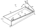
- FIG. 6 is a perspective view showing a perspective structure of the fuel filter case.
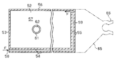
- FIG. 7 is a cross-sectional view showing the cross-sectional structure of the fuel filter case, and is a cross-sectional view for explaining the communication path 59.
- FIG. 8 is a cross-sectional view showing a cross-sectional structure of the fuel filter case, and includes a suction part 61.
- the case 22 has a case main body 51 formed in a bottomed box shape having an opening on the top surface.
- the case main body 51 includes a rectangular plate-like bottom wall 52 and peripheral walls 53, 54, 55, and 56 standing from the peripheral edge of the bottom wall 52, and the bottom wall 52 and the peripheral walls 53, 54, 55,
- the housing space 57 is an internal space surrounded by 56.
- the case 22 is suspended from the fuel tank 11 so as to be inclined with respect to the bottom surface of the fuel tank 11 so that only the corner portion constituted by the bottom wall 52 and the peripheral wall 53 is in contact with the bottom surface of the fuel tank 11. (See FIG. 1).
- the peripheral wall 53 and the peripheral wall 55 facing the peripheral wall 53 are formed in such a manner that the width in the height direction becomes relatively large at the peripheral wall 53 disposed on the bottom surface side of the fuel tank 11.
- the peripheral walls 54 and 56 connecting the peripheral walls 53 and 55 are formed in accordance with the height difference of the peripheral walls 53 and 55 so that the width in the height direction continuously decreases from the peripheral wall 53 toward the peripheral wall 55.
- the fuel filter device 20 is disposed to be inclined, more fuel F is stored in the housing space 57 on the peripheral wall 53 side than on the peripheral wall 55 side.
- a first suction port 58 extending from the bottom wall 52 toward the top surface is formed at a corner portion formed by the peripheral wall 53 and the peripheral wall 54 in the case main body 51.
- the peripheral wall 54 and the peripheral wall 55 are formed with a communication path 59 that is a groove opened on the top surface along the peripheral wall 54 and the peripheral wall 55, and the communication path 59 serves as the first suction port 58 and the accommodation space 57. And communicate with each other.
- the communication path 59 has a labyrinth structure that passes around the accommodation space 57 and communicates with the accommodation space 57. Further, in the communication path 59, the height from the bottom wall 52 to the bottom surface of the groove gradually increases from the first suction port 58 to the accommodation space 57.
- the communication path 59 having such a labyrinth structure, even if the posture of the case 22 changes, the fuel F once stored in the accommodation space 57 flows out from the first suction port 58 through the communication path 59. Can be suppressed.
- the height from the bottom wall 52 to the bottom surface of the groove gradually increases from the first suction port 58 to the accommodation space 57, if there is no fuel F in the accommodation space 57, the accommodation space 57 leads to the communication path 59. Fuel F does not flow out. Thereby, it is possible to further suppress the fuel F in the accommodation space 57 from flowing out through the communication path 59. Therefore, the fuel F before filtration can be reliably stored in the accommodation space 57.
- the bottom wall 52 of the case main body 51 is provided with a suction portion 61, which is a cylindrical body extending toward the top surface, near the peripheral wall 53.
- the suction portion 61 introduces the fuel F into the accommodation space 57 through the second suction port 62 provided in the bottom wall 52 of the case body 51. That is, by providing such a suction portion 61, the fuel F is also sucked into the accommodation space 57 through the bottom wall 52 of the case 22.
- the suction portion 61 protrudes from the bottom wall 52 toward the top surface, the fuel F before filtration can be stored in the accommodation space 57 at least by the height of the suction portion 61. .
- the case 22 has a lid 65.
- the lid 65 is configured in a plate shape so as to cover a part of the opening of the case body 51, and is rotatably connected to the peripheral wall 55 by an opening / closing mechanism included in the case 22.
- the opening / closing mechanism of the case 22 is, for example, a hinge mechanism, and is configured such that its rotation is restricted when a part of the opening (inlet) of the case body 51 is covered by the lid 65.
- a clamp 66 into which the above-described connecting member 44 is fitted is formed on the peripheral wall 53 side of the lid body 65.
- the intermediate portion 48 of the connecting member 44 of the fuel filter 21 is fitted into the clamp 66 of the lid 65, whereby the case 22 is connected to the fuel filter 21 and the case 22 is positioned relative to the fuel filter 21. Is done.
- the liquid level position of the fuel in the fuel tank 11 also changes according to the shape of the fuel tank 11. Become. The relative position between the fuel level in the fuel tank 11 and the fuel filter 21 suspended from the fuel tank 11 also changes.
- the case 22 disposed in the fuel tank 11 accommodates the fuel filter 21 and the fuel F.
- the case 22 and the fuel filter 21 are suspended in the fuel tank 11 while the case 22 is positioned on the fuel filter 21. Therefore, for example, even if the posture of the vehicle is inclined with respect to the horizontal direction, it is possible to maintain the relative positions of the fuel F and the fuel filter 21 in the case 22. Therefore, regardless of the posture of the vehicle, it is possible to immerse the fuel filter 21 in the fuel, and thus improve the startability of the fuel supply via the fuel filter 21.
- the fuel filter 21 is carried into the fuel tank 11 through the carry-in port 14 provided in the fuel tank 11.
- the case 22 is positioned with respect to the fuel filter 21, and the fuel filter 21 is connected to the fuel pump 13. Therefore, when the fuel filter 21 is disposed in the fuel tank 11, the case 22 that accommodates the fuel filter 21 needs to be temporarily deformed depending on the shape of the carry-in port 14.
- the filter member 24 can be bent by the frame member 25, and the lid body 65 in which the clamp 66 that fits the intermediate portion 48 of the fuel filter 21 is formed. Is rotated with respect to the case main body 51 by the opening / closing mechanism. Therefore, for example, as shown in FIG. 9, the lid 65 is rotated with respect to the case main body 51 by the opening / closing mechanism from the state in which the fuel filter 21 is accommodated in the case 22 (the state of the two-dot chain line in FIG. 9). To do. Then, the case 22 is arranged along the vertical direction, and the fuel filter 21 extending in the horizontal direction is bent in the middle thereof (the state of the solid line in FIG. 9).
- the orientation and position of the case body 51 with respect to the fuel pump 13 can be changed according to the shape of the carry-in port 14, and the filter member 24 can be bent according to the shape of the carry-in port 14.
- the application range of the case 22 can be greatly expanded as compared with the configuration in which the lid 65 is fixed to the case main body 51.
- the fuel filter 21 in the case 22 the fuel F is stored in the storage space 57 of the case 22, so that the chamber for storing the fuel F does not have to be disposed in the fuel tank 11. Good.
- the fuel tank 11 can also be made into a simpler structure.
- the case main body 51 formed in the shape of a bottomed box is suspended from the fuel tank 11 in a state where the fuel filter 21 and the fuel F before filtration are accommodated in the accommodation space 57. While being lowered, the fuel filter 21 is positioned. Therefore, for example, even if the posture of the vehicle is inclined with respect to the horizontal direction, it is possible to maintain the relative positions of the fuel F and the fuel filter 21 in the case 22. Therefore, regardless of the posture of the vehicle, it is possible to immerse the fuel filter 21 in the fuel, and thus improve the startability of the fuel supply via the fuel filter 21.
- the peripheral walls 54 and 55 of the case body 51 of the above embodiment form a labyrinth structure that passes around the accommodation space 57 to communicate the first suction port 58 and the accommodation space 57. Is formed. According to such a configuration, even if the posture of the vehicle is changed and the case 22 is inclined, the fuel F in the accommodation space 57 can be prevented from flowing out from the first suction port 58 through the communication path 59. Therefore, the fuel F before filtration can be reliably stored in the accommodation space 57.
- the communication passage 59 of the above embodiment is formed in a groove shape in the peripheral walls 54 and 55 so that the height from the bottom wall 52 to the bottom surface of the groove gradually increases from the first suction port 58 to the accommodation space 57. Is formed. According to such a configuration, even if the fuel filter device 20 is inclined, the fuel passage device 59 does not flow into the communication passage 59 unless there is a certain amount of fuel F in the accommodation space 57. Thereby, it is possible to further suppress the fuel F in the accommodation space 57 from flowing out through the communication passage 59.
- the bottom wall 52 of the case body 51 is formed with the second suction port 62 and the cylindrical suction portion 61 extending toward the opening of the case body 51. According to such a configuration, the fuel F is sucked into the accommodation space 57 through the bottom wall 52 of the case body 51 by the operation of the fuel pump 13. Therefore, even if the fuel in the fuel tank 11 decreases, the fuel F can be reliably introduced into the accommodation space 57.
- the case 22 of the above embodiment has an opening / closing mechanism that allows the lid 65 to rotate with respect to the peripheral wall 55. According to such a configuration, the orientation and position of the case main body 51 with respect to the fuel pump 13 can be changed, so that the application range of the case 22 is greatly increased compared to the configuration in which the lid 65 is fixed to the case main body 51. Can be expanded.
- the filter member 24 When the filter member 24 is accommodated in the case 22 as in the above embodiment, the filter member 24 can be protected during the flow of the fuel filter device 20. Thereby, the filter member 24 becomes difficult to be damaged, and the performance of the filter member 24 can be made more reliable.
- the said embodiment can also be implemented with the following aspects.
- the lid body 65 of the case 22 is configured to be rotatable with respect to the case body 51.
- the configuration is not limited to this, and the lid 65 of the fuel filter case 22 may be fixed to the case body 51. Even with such a configuration, the same effects as described in the above (1) to (5) can be obtained.
- the bottom wall 52 of the case body 51 is provided with the second suction port 62 and the cylindrical suction portion 61 extending toward the opening formed by the peripheral walls 53 to 56.
- the two suction ports 62 and the suction part 61 may be omitted. Even with such a configuration, the same effects as described in the above (1) to (4) can be obtained, and the fuel F does not flow out from the bottom wall 52. Therefore, the fuel F is stored in the accommodation space 57. Is more certain.
- the communication passage 59 of the above embodiment is formed in a groove shape on the peripheral walls 54 and 55, and is formed so that the height from the bottom wall 52 to the bottom surface of the groove gradually increases from the first suction port 58 to the accommodation space 57. ing.
- the height of the communication path from the bottom wall 52 to the bottom surface of the groove may be constant from the first suction port 58 to the accommodation space 57, or may gradually decrease. Even with such a configuration, the same effects as described in the above (1) to (3) can be obtained.
- the communication path 59 that allows the first suction port 58 and the accommodation space 57 to communicate with each other has a labyrinth structure that passes around the accommodation space 57.
- the communication path is not limited to this, as long as the first suction port 58 and the accommodation space 57 are in communication with each other.
- grooves continuous to the communication path 59 may be provided in the peripheral walls 56 and 53. It may be a through hole provided in the peripheral wall 53. Even if it is such a structure, the effect similar to the effect described in said (1) (2) can be acquired.
- the positioning part of the above embodiment is a clamp that is coupled to the connecting member 44 that is a connecting pipe
- the positioning part is limited to the clamp 66 as long as the positioning part is configured to position the fuel filter 21 by being formed on the lid 65. is not.
- the fuel filter case has the first suction port 58 and the second suction port 62.
- the fuel filter case has only the first suction port 58, or for the fuel filter.
- the case may have a configuration having only the second suction port 62.
- the inflow port of the above embodiment has a configuration in which the entire top surface of the case body 51 is opened.
- the inflow port may be an opening formed in the top wall of the case body 51.
- the case main body 51 of the said embodiment was comprised with the rectangular-plate-shaped bottom wall 52, you may change this and may comprise a case main body using a circular-plate-shaped bottom wall, for example.
- the filter sheet 23 of the above embodiment has a four-layer structure in which the nonwoven fabrics 26a, 26b, 26c and the mesh fabric 27 are laminated, but is not limited to a four-layer structure as long as a welded portion is formed.
- the frame member 25 of the above embodiment has one bent portion 41. However, the frame member 25 may have a plurality of bent portions.
- the fuel tank 11 is not provided with a chamber.
- the fuel filter device 20 may be arranged in the chamber provided in the fuel tank 11 by changing the chamber.
Landscapes
- Engineering & Computer Science (AREA)
- Chemical & Material Sciences (AREA)
- Combustion & Propulsion (AREA)
- Mechanical Engineering (AREA)
- General Engineering & Computer Science (AREA)
- Chemical Kinetics & Catalysis (AREA)
- Filtration Of Liquid (AREA)
- Cooling, Air Intake And Gas Exhaust, And Fuel Tank Arrangements In Propulsion Units (AREA)
Abstract
燃料フィルター用ケースは、燃料タンクに吊り下げられる燃料フィルターと燃料とが収容される収容空間を有した箱状に形成されるとともに、燃料タンク内の燃料が収容空間に流入する流入口を天面に有するケース本体と、流入口の一部を覆うようにケース本体に連結されるとともに、燃料フィルターに連結されて該燃料フィルターに位置決めされるクランプを有する蓋体とを備える。そして、この燃料フィルター用ケースにクランプで位置決めされた燃料フィルターが収容されて、燃料用フィルター装置が構成される。
Description
本発明は、燃料タンク内で燃料を濾過する燃料フィルターに使用される燃料フィルター用ケース、及び、燃料タンク内で燃料を濾過する燃料フィルターを備えた燃料フィルター装置に関する。
自動車や自動二輪車等における燃料タンク内の燃料は、通常、燃料タンク内に配設された燃料フィルター装置を通して内燃機関に供給される。こうした燃料フィルター装置は、燃料ポンプを介して燃料タンク内に吊り下げられる燃料フィルターを有しており、該燃料フィルターとしては、例えば特許文献1に記載のように、メッシュ織物や不織布等の濾材シートから形成される袋状のフィルター部材を用いるものが知られている。
特許文献1に記載のフィルター部材は、一つの折り目で二重に折り重ねられた濾材シートを有し、該折り目で区画された一対のシート部分が互いの縁で溶着されることにより袋状に形成されている。また、袋状に形成されたフィルター部材の内部には、一対のシート部分を該内部において互いに離間させる骨格としてのフレーム部材が配設されている。そして、一対のシート部分の各々で濾過された燃料は、これらシート部分で囲まれるフィルター部材の内部を通して内燃機関へ供給される。このような構成によれば、フィルター部材の外表面が一対のシート部分によって構成されるため、フィルター部材が有する外表面の略全体で濾過機能が発現するようになる。
ところで、内燃機関の再始動時に燃料フィルターを通してチャンバ内の燃料を供給するためには、濾過前の燃料にフィルター部材を浸しておくことが必要である。しかしながら、上述した燃料フィルターでは、燃料タンク内の燃料が少なく、且つチャンバの隅に燃料が偏るような姿勢で車両が停止すると、チャンバと燃料フィルターとの相対位置がずれてしまい、チャンバ内に燃料が残っているにもかかわらず、フィルター部材の一部あるいは全部が燃料に浸らなくなる場合がある。こうした状況下においては、フィルター部材で濾過可能な燃料が減少するため、内燃機関の再始動時に該内燃機関に対して十分な燃料を供給することができなくなる虞がある。
本発明は、上記実状を鑑みてなされたものであり、その目的は、燃料フィルターを介した燃料供給の始動性を高めることの可能な燃料フィルター用ケース及び燃料フィルター装置を提供することにある。
本発明の第1観点によれば、燃料タンクに吊り下げられる燃料フィルターと燃料とが収容される収容空間を有した箱状に形成されるとともに、前記燃料タンク内の燃料が前記収容空間に流入する流入口を天面に有するケース本体と、前記流入口の一部を覆うように前記ケース本体に連結されるとともに、前記燃料フィルターに連結されて前記燃料フィルターに位置決めされる位置決め部を有する蓋体とを備えることを要旨とする燃料フィルター用ケースを提供する。
本発明の好ましい態様では、前記位置決め部が、前記燃料フィルターにて燃料ポンプに接合する部分である連結管に連結するクランプであることを要旨とする。具体的に位置決め部は、この好ましい態様のように、燃料フィルターにて燃料ポンプに接合する部分である接合間と連結するクランプによって構成することができる。
本発明の好ましい態様では、前記ケース本体が、前記流入口よりも底側に形成されて燃料ポンプの吸引によって前記収容空間に燃料を吸引する吸引口と、前記吸引口と前記収容空間とを連通する連通路とを備え、前記連通路は、前記収容空間内の燃料が前記吸引口から流出することを抑えるラビリンス構造を有することを要旨とする。
この好ましい態様によれば、上記連通路を通じて収容空間内の燃料が吸引口から流出することが抑えられることから、燃料フィルター用ケース内における燃料の貯留性を高めることが可能である。
本発明の好ましい態様では、前記ケース本体が、燃料ポンプの吸引によって前記収容空間に燃料を吸引する吸引口が形成された底壁と、前記吸引口から前記天面側に向かって延びるように形成されて前記吸引口と前記収容空間とを連通する筒体とを備えることを要旨とする。
この好ましい態様によれば、底壁に形成された吸引口を通じて収容空間に燃料を吸引することができる。これにより、燃料タンク内の燃料が少なくなったときであっても、収容空間に燃料を吸引することができる。また天面側に向かって延びる筒体を介して吸引口と収容空間とが連通していることから、少なくとも筒体の高さに応じた分の燃料を収容空間に貯留することができる。
本発明の好ましい態様では、前記流入口を開閉するように前記ケース本体に対して前記蓋体を回動可能にする開閉機構を備えることを要旨とする。
燃料フィルターは、通常、燃料タンクに設けられた開口を通して燃料タンク内に配置される。この際、燃料フィルターに位置決めされた燃料フィルター用ケースも同開口を通して燃料タンク内に配置される。この好ましい態様によれば、燃料フィルター用ケースを位置決めする蓋体がケース本体に対して回動可能であることから、燃料フィルターに対するケース本体の向きや位置を変更することができる。その結果、燃料タンクの開口の形状に合わせて、燃料フィルター用ケースと燃料フィルターとの相対位置を変えることができる。それゆえに、蓋体がケース本体に固定されている構成に比べて、燃料フィルター用ケースの適用範囲を大幅に拡げることができる。
燃料フィルターは、通常、燃料タンクに設けられた開口を通して燃料タンク内に配置される。この際、燃料フィルターに位置決めされた燃料フィルター用ケースも同開口を通して燃料タンク内に配置される。この好ましい態様によれば、燃料フィルター用ケースを位置決めする蓋体がケース本体に対して回動可能であることから、燃料フィルターに対するケース本体の向きや位置を変更することができる。その結果、燃料タンクの開口の形状に合わせて、燃料フィルター用ケースと燃料フィルターとの相対位置を変えることができる。それゆえに、蓋体がケース本体に固定されている構成に比べて、燃料フィルター用ケースの適用範囲を大幅に拡げることができる。
また、本発明の第2観点によれば、燃料フィルターと、前記燃料フィルターを収容する燃料フィルター用ケースとを備える燃料フィルター装置であって、前記燃料フィルター用ケースは、本発明の第1観点による燃料フィルター用ケースであることを要旨とする燃料フィルター装置を提供する。
上述したように、車両に固定された燃料タンク内においては、例えば車両の姿勢が水平方向に対して傾くと、燃料タンクの形状に応じて、燃料タンクにおける燃料の液面位置も変わることになる。そして、燃料タンクにおける燃料の液面位置と燃料タンクに吊り下げられた燃料フィルターとの相対的な位置も変わることとなる。
この点、本発明による燃料フィルター用ケースにおいては、燃料タンクに配置される燃料フィルター用ケースが、燃料フィルターと燃料とを収容する。そして、この燃料フィルター用ケースが燃料フィルターに位置決めされた状態で、該燃料フィルター用ケースと燃料フィルターとが燃料タンクに吊り下げられる。それゆえに、例えば車両の姿勢が水平方向に対して傾いたとしても、燃料フィルター用ケース内の燃料と燃料フィルターとの相対的な位置を維持することが可能である。それゆえに、車両の姿勢にかかわらず、燃料フィルターを燃料に浸すこと、ひいては燃料フィルターを介した燃料供給の始動性を高めることが可能である。
また、本発明による燃料フィルター装置によれば、燃料フィルター用ケースに濾過前の燃料を貯留しておくこと、燃料フィルター用ケースが貯留している燃料に燃料フィルターを浸しておくこと、これらが可能となる。
以下、本発明に係る燃料フィルター用ケース及び燃料フィルター装置の一実施の形態について図1~図9を参照して説明する。まず、燃料フィルター装置が用いられる燃料供給装置について説明する。図1は、燃料フィルター装置を用いた燃料供給装置の概略構成を模式的に示す図である。
図1に示されるように、燃料供給装置10は、燃料Fが貯留された燃料タンク11と、該燃料タンク11内に配置された燃料ポンプ13及び燃料フィルター装置20とを有している。燃料フィルター装置20は、燃料タンク11の底面に対して傾斜した状態で燃料タンク11の上面から吊り下げられており、燃料Fを濾過する燃料フィルター21と、燃料フィルター21を収容する燃料フィルター用ケース22(以下では、単にケース22という。)を有している。なお、図1では、燃料フィルター装置20が燃料タンク11の底面に接触するように燃料フィルター装置20が吊り下げられているが、燃料フィルター装置20が燃料タンク11の底面から離れるように燃料フィルター装置20が吊り下げられてもよい。
燃料フィルター21は、連結管としての連結部材44を介して燃料ポンプ13に接続されている。燃料ポンプ13は、搬入口14を塞ぐフランジ15によって燃料タンク11に固定された供給用配管16に接続されている。そして燃料供給装置10は、燃料ポンプ13が駆動されることによって、燃料タンク11内の燃料Fを燃料フィルター装置20で濾過し、供給用配管16を通じて、その濾過された燃料Fを内燃機関17へ供給する。
次に、上述した燃料フィルター装置20について図2~図9を参照して詳しく説明する。図2は、燃料フィルター装置の斜視構造を示す斜視図である。
図2に示されるように、燃料フィルター装置20は、燃料フィルター21と、該燃料フィルター21を収容するとともに該燃料フィルター21に対して位置決めされるケース22とで構成される。ケース22は、天面に開口(流入口)を有した有底箱体状に形成されており、収容空間57に燃料フィルター21が収容される。ケース22は、その周壁の1つに蓋体65が連結されており、この蓋体65の先端部に設けられたクランプ66が燃料フィルター21の連結部材44と結合することにより、燃料フィルター21に対してケース22が位置決めされている。
図2に示されるように、燃料フィルター装置20は、燃料フィルター21と、該燃料フィルター21を収容するとともに該燃料フィルター21に対して位置決めされるケース22とで構成される。ケース22は、天面に開口(流入口)を有した有底箱体状に形成されており、収容空間57に燃料フィルター21が収容される。ケース22は、その周壁の1つに蓋体65が連結されており、この蓋体65の先端部に設けられたクランプ66が燃料フィルター21の連結部材44と結合することにより、燃料フィルター21に対してケース22が位置決めされている。
まず、燃料フィルター21について図3~図5を参照して説明する。図3(a)は、燃料フィルターの斜視構造を示す斜視図であって、フィルター部材の一部を切り欠いて燃料フィルターの内部構造を示す図である。図3(b)は、溶着部における濾材シートの断面構造を示す断面図である。図4は、フレーム部材の斜視構造を示す斜視図である。図5は、連結部付近における燃料フィルターの断面構造を示す断面図である。
図3(a)に示されるように、燃料フィルター21は、互いに対向するシート部分23a,23bによって扁平な袋状に形成されるフィルター部材24と、該フィルター部材24内に配設されるフレーム部材25と、フィルター部材24の外側に突出させた連結部材44とを有している。
フィルター部材24は、複数のシート状の合成繊維が積層された1枚の濾材シート23から形成されている。フィルター部材24は、一つの折り目で二重に折り重ねられた上記濾材シート23を有し、該折り目で区画された上側シート部分23aと下側シート部分23bとが互いの縁で溶着されることにより袋状に形成されている。図3(b)に示されるように、本実施形態の濾材シート23は、ポリプロピレン繊維で形成された不織布26aを最内層として有し、油と水とを分離可能な平織りのメッシュ織物27を最外層として有している。これら不織布26aとメッシュ織物27との間には、内側に位置するものほどメッシュのサイズが小さくなるように、不織布26b,26cが積層されている。
こうした濾材シート23で構成されるフィルター部材24においては、外側に位置する層で粒径の大きな異物が捕捉され、内側に位置する層で粒径の小さな異物が捕捉される。すなわち、サイズの異なる異物が互いに異なる層で捕捉されるため、各層における目詰まりを抑えることができる。なお、スパンボンド法で形成された不織布を最内層である不織布26aに採用し、且つメルトブロウン法で形成された不織布を中間層である不織布26b,26cに採用すれば、相対的に高い剛性が不織布26aに与えられるため、不織布26aとフレーム部材25との擦れによって不織布からパーティクルが発生することを抑えることができる。
濾材シート23には、最内層となる不織布26a側から不織布26a,26b,26c、メッシュ織物27を超音波溶着法で溶着させた複数の溶着部28が離散的に設けられている。複数の溶着部28の各々は、フィルター部材24の内面に円形孔状に形成されている。このような溶着部28が形成されることによって、積層された不織布26a,26b,26c、及びメッシュ織物27が互いに固定される。そのため、燃料フィルター装置20の使用時において、これら不織布26a,26b,26c、及びメッシュ織物27が互いにずれることを抑えることが可能である。また、不織布26a,26b,26c、及びメッシュ織物27が積層された母材から濾材シート23を切り出すこと、さらには、これらが積層された状態で燃料フィルター装置20を組み立てることが可能である。
フィルター部材24内に配設されるフレーム部材25は、可撓性を有する合成樹脂で形成されている。図4に示されるように、フレーム部材25は、長手方向に直線状に延びる複数の第1フレーム31と、長手方向に直交する短手方向に直線状に延びる複数の第2フレーム32とによって構成される格子状のベースフレーム30を有している。ベースフレーム30には、第1フレーム31と第2フレーム32とが交差する箇所に、下側シート部分23bに向かって突出するフレームリブ33が設けられている。このフレームリブ33は、その先端がフィルター部材24の内面に当接し、該先端がフィルター部材24の内面をフィルター部材24の外側へ押すことによって、ベースフレーム30と下側シート部分23bとの間隔を保持する。なお、このフレームリブ33は、フィルター部材24の外表面に対向する平面視において、すなわち下側シート部分23bに対向する平面視において、溶着部28よりも大きくなるように形成されている。
また、ベースフレーム30は、連結部材44が連結される連結部35を有している。連結部35は、第1フレーム31及び第2フレーム32に支持される略円筒状のフランジ部36と、フランジ部36から上記フレームリブ33とは反対方向に延びる略円筒状の吸込み部37とを有している。また連結部35には、フランジ部36から下側シート部分23b側に突出する4つの吸込み用リブ39がフランジ部36の周方向に等配されている。この吸込み用リブ39は、フィルター部材24の内面に当接して連結部35のフランジ部36と下側シート部分23bとの間隔を保持し、吸込み部37が下側シート部分23bで塞がれることを防止する。図5に示されるように、連結部35におけるフランジ部36の一部は、上側シート部分23aに設けられた貫通孔40を通してフィルター部材24の外側に露出している。また、連結部35における吸込み部37は、同貫通孔40を通してフィルター部材24の外側に突出する。
ベースフレーム30は、長手方向の中央よりも連結部35側に、ベースフレーム30の短手方向の全幅にわたる屈曲部分41を有している。屈曲部分41は、ベースフレーム30において、該屈曲部分41以外の部分よりも、隣り合う第1フレーム31の間隔が大きく、且つ隣り合う第2フレーム32の間隔が大きい部分である。屈曲部分41を構成する各第1フレーム31には、屈曲部として、短手方向に並ぶように、肉厚が薄い薄肉部42が設けられている。すなわち屈曲部分41は、他の部分よりも剛性が低くなるように構成されており、フレーム部材25に外力が作用したときには、該屈曲部分41以外の部分よりも優先的に屈曲される部分である。こうした屈曲部分41が設けられることによって、屈曲部分41が設けられていない構成のフレーム部材に比べて、上記外力に基づくフレーム部材25への機械的な負荷を軽減することができる。
このように構成されることによって、上側シート部分23aは、ベースフレーム30そのものによって、燃料フィルター21の外側へ押される。また、下側シート部分23bは、フレームリブ33、及び吸込み用リブ39によって、これもまた燃料フィルター21の外側へ押される。それゆえに、上側シート部分23aと下側シート部分23bとの間隔が保持され、これにより上側シート部分23aと下側シート部分23bとの間に所定のサイズで貯留空間43が形成される。そして、上側シート部分23aの略全体と下側シート部分23bの略全体とで濾過された燃料Fが、こうした貯留空間43を通じて吸込み部37に流入する。
図5に示されるように、連結部材44は、下端部46と、上端部47と、これら下端部46と上端部47とを繋ぐ円筒状の中間部48とを有している。連結部材44の下端部46は、フレーム部材25の連結部35に連結され、連結部材44の上端部47は、燃料ポンプ13に連結される(図1参照)。連結部材44には、下端部46から上端部47までを貫通するように連絡通路45が形成され、この連絡通路45には、その下端部46側において連結部35の吸込み部37が挿入される。また連結部材44の下端部46は、連結部35のフランジ部36と該下端部46とによって上側シート部分23aが挟持された状態で、フランジ部36に連結されている。そして、燃料ポンプ13が稼動すると、吸込み部37に流入した燃料Fは、連結部材44の連絡通路45を通じて燃料ポンプ13に導入される。また、連結部材44の中間部48には、図2に示されるように、係止部49が設けられている。そして、この係止部49と下端部46との隙間を通って、ケース22の蓋体65に設けられたクランプ66に中間部48が嵌め込まれる。これにより、燃料フィルター21とケース22とが接合されて、燃料フィルター21に対してケース22が位置決めされている。
次に、燃料フィルター用ケース22について図6~図8を参照して説明する。図6は、燃料フィルター用ケースの斜視構造を示す斜視図である。図7は、燃料フィルター用ケースの断面構造を示す断面図であって、連通路59を説明するための断面図である。図8は、燃料フィルター用ケースの断面構造を示す断面図であって、吸入部61を含む断面図である。
図6に示されるように、ケース22は、天面に開口を有する有底箱体状に形成されたケース本体51を有している。ケース本体51は、矩形板状の底壁52と、底壁52の周縁部から立設された周壁53,54,55,56とを有するとともに、これら底壁52及び周壁53,54,55,56で囲まれる内部空間である収容空間57を有している。ケース22は、底壁52と周壁53とから構成される角部のみが燃料タンク11の底面に接触するように、燃料タンク11の底面に対して傾斜するように燃料タンク11に吊り下げられている(図1参照)。周壁53と該周壁53に対向する周壁55とは、その高さ方向の幅が燃料タンク11の底面側に配置される周壁53にて相対的に大きくなるかたちに形成されている。また、これら周壁53,55を繋ぐ周壁54,56は、その高さ方向の幅が周壁53から周壁55に向けて連続的に小さくなるように、これら周壁53,55の高低差に合わせて形成されている。このような構成によれば、燃料フィルター装置20が傾斜して配置されると、収容空間57において、周壁53側で周壁55側よりも多くの燃料Fが貯留される。
また、ケース本体51において周壁53と周壁54とが形成する角部には、底壁52から天面に向けて延びる第一吸引口58が形成されている。また、周壁54及び周壁55には、天面に開口した溝である連通路59が周壁54及び周壁55に沿って形成されており、この連通路59が上記第一吸引口58と収容空間57とを連通させている。連通路59は、図6及び図7に示されるように、収容空間57の周りを通って収容空間57に連通するラビリンス構造を有している。また、この連通路59においては、底壁52から溝の底面までの高さが第一吸引口58から収容空間57にかけて徐々に高くなる。
こうしたラビリンス構造を有する連通路59によれば、たとえケース22の姿勢が変化したとしても、収容空間57に一旦貯留された燃料Fが該連通路59を介して第一吸引口58から流出することを抑えることができる。そのうえ、底壁52から溝の底面までの高さが第一吸引口58から収容空間57にかけて徐々に高くなるため、収容空間57内にある程度の燃料Fがなければ収容空間57から連通路59へ燃料Fが流出しない。これにより、収容空間57内の燃料Fが連通路59を介して流出することをさらに抑えることができる。それゆえに、濾過前の燃料Fを収容空間57に確実に貯留させておくことができる。
また、ケース本体51の底壁52には、図8にも示されるように、天面側に向かって延びる円筒体である吸入部61が周壁53寄りに設けられている。そして、燃料ポンプ13が燃料Fの吸引を開始すると、吸入部61は、ケース本体51の底壁52に設けられた第二吸引口62を通じて収容空間57に燃料Fを導入する。すなわち、こうした吸入部61が設けられることによって、ケース22の底壁52を通じても燃料Fが収容空間57に吸入される。また、吸入部61が底壁52から天面側に向かって突出していることから、少なくとも吸入部61の高さの分だけ、濾過前の燃料Fを収容空間57に貯留することが可能である。
また、図6に示されるように、ケース22は、蓋体65を有している。蓋体65は、ケース本体51の開口の一部を覆うような板状に構成されており、ケース22が有する開閉機構によって周壁55に回動可能に連結されている。ケース22が有する開閉機構は、例えば、ヒンジ機構であって、蓋体65によってケース本体51の開口(流入口)の一部が覆われたときにその回動が規制されるように構成されていることが好ましい。また、蓋体65における周壁53側には、上述した連結部材44が嵌め込まれるクランプ66が形成されている。そして、燃料フィルター21の連結部材44における中間部48が蓋体65のクランプ66に嵌め込まれることによって、燃料フィルター21に対してケース22が接続されるとともに、燃料フィルター21に対してケース22が位置決めされる。
ここで、車両に固定された燃料タンク11内においては、例えば車両の姿勢が水平方向に対して傾くと、燃料タンク11の形状に応じて、燃料タンク11における燃料の液面位置も変わることになる。そして、燃料タンク11における燃料の液面位置と燃料タンク11に吊り下げられた燃料フィルター21との相対的な位置も変わることとなる。
この点、上述した構成によれば、燃料タンク11に配置されるケース22が、燃料フィルター21と燃料Fとを収容する。そして、このケース22が燃料フィルター21に位置決めされた状態で、該ケース22と燃料フィルター21とが燃料タンク11内に吊り下げられる。それゆえに、例えば車両の姿勢が水平方向に対して傾いたとしても、ケース22内の燃料Fと燃料フィルター21との相対的な位置を維持することが可能である。それゆえに、車両の姿勢にかかわらず、燃料フィルター21を燃料に浸すこと、ひいては燃料フィルター21を介した燃料供給の始動性を高めることが可能である。
また、図1に示したように、燃料フィルター21は、燃料タンク11に設けられた搬入口14を通して燃料タンク11内に搬入される。この際、ケース22は燃料フィルター21に対して位置決めされ、且つ、燃料フィルター21は燃料ポンプ13に連結されている。そのため、燃料フィルター21を燃料タンク11内に配設するとき、搬入口14の形状によっては、該燃料フィルター21を収容したケース22を一時的に変形させる必要がある。
これに対し、上述した構成の燃料フィルター装置20によれば、フィルター部材24がフレーム部材25によって屈曲可能であるとともに、燃料フィルター21の中間部48に嵌合するクランプ66が形成された蓋体65が開閉機構によってケース本体51に対して回動する。そのため、例えば図9に示されるように、燃料フィルター21がケース22内に収容される状態(図9における二点差線の状態)から、蓋体65が開閉機構によってケース本体51に対して回動する。そして、ケース22が鉛直方向に沿うように配置されるとともに、水平方向に延びる燃料フィルター21がその途中で折り曲げられる(図9における実線の状態)。すなわち、搬入口14の形状に合わせて、燃料ポンプ13に対するケース本体51の向きや位置を変更すること、また搬入口14の形状に合わせて、フィルター部材24を屈曲させることが可能である。こうした構成によれば、蓋体65がケース本体51に固定されている構成に比べて、ケース22の適用範囲を大幅に拡げることができる。しかも、こうしたケース22内に燃料フィルター21を収容することによって、ケース22の収容空間57に燃料Fが貯留されることから、燃料Fを貯留するチャンバを燃料タンク11内に配設しなくてもよい。これにより、燃料タンク11をより簡易な構成とすることもできる。
以上説明したように、本実施の形態に係る燃料フィルター用ケース22及び燃料フィルター装置20によれば、以下列記するような効果が得られるようになる。
(1)上記実施形態によれば、有底箱体状に形成されたケース本体51は、燃料フィルター21と濾過前の燃料Fとが収容空間57に収容された状態で、燃料タンク11に吊り下げられるとともに、燃料フィルター21に対して位置決めされる。それゆえに、例えば車両の姿勢が水平方向に対して傾いたとしても、ケース22内の燃料Fと燃料フィルター21との相対的な位置を維持することが可能である。それゆえに、車両の姿勢にかかわらず、燃料フィルター21を燃料に浸すこと、ひいては燃料フィルター21を介した燃料供給の始動性を高めることが可能である。
(1)上記実施形態によれば、有底箱体状に形成されたケース本体51は、燃料フィルター21と濾過前の燃料Fとが収容空間57に収容された状態で、燃料タンク11に吊り下げられるとともに、燃料フィルター21に対して位置決めされる。それゆえに、例えば車両の姿勢が水平方向に対して傾いたとしても、ケース22内の燃料Fと燃料フィルター21との相対的な位置を維持することが可能である。それゆえに、車両の姿勢にかかわらず、燃料フィルター21を燃料に浸すこと、ひいては燃料フィルター21を介した燃料供給の始動性を高めることが可能である。
(2)また、燃料フィルター装置20にケース22を設けることによって、燃料タンク11に燃料貯留用のチャンバを設けなくて済むことから、燃料タンク11をより簡易な構成とすることができる。
(3)上記実施形態のケース本体51の周壁54,55には、収容空間57の周りを通るラビリンス構造をなして、第一吸引口58と収容空間57とを連通させる溝状の連通路59が形成されている。こうした構成によれば、たとえ車両の姿勢が変化してケース22が傾いたとしても、収容空間57内の燃料Fが連通路59を通じて第一吸引口58から流出することを抑えることができる。それゆえに、濾過前の燃料Fが収容空間57内に確実に貯留させることができる。
(4)上記実施形態の連通路59は、周壁54,55に溝状に形成され、底壁52から溝の底面までの高さが第一吸引口58から収容空間57にかけて徐々に高くなるように形成されている。こうした構成によれば、燃料フィルター装置20が傾斜したとしても、収容空間57内にある程度の燃料Fがなければ連通路59に流入することがない。これにより、収容空間57内の燃料Fが連通路59を通じて流出することをさらに抑えることができる。
(5)上記実施形態において、ケース本体51の底壁52には、第二吸引口62と、該ケース本体51の開口に向かって延びる筒状の吸入部61とが形成されている。こうした構成によれば、燃料ポンプ13の稼動によって、ケース本体51の底壁52を通じて収容空間57に燃料Fが吸入される。そのため、燃料タンク11内の燃料が少なくなったとしても、収容空間57に確実に燃料Fを導入することができる。
(6)上記実施形態のケース22は、蓋体65を周壁55に対して回動可能にする開閉機構を有している。こうした構成によれば、燃料ポンプ13に対するケース本体51の向きや位置を変更することができることから、蓋体65がケース本体51に固定されている構成に比べて、ケース22の適用範囲を大幅に拡げることができる。
(7)上記実施形態のようにフィルター部材24がケース22に収容されることによって、燃料フィルター装置20の流通過程においてフィルター部材24を保護することができる。これにより、フィルター部材24が傷つきにくくなり、該フィルター部材24の性能をより確実なものとすることができる。
なお、上記実施の形態は、以下のような態様をもって実施することもできる。
上記実施形態では、ケース22の蓋体65をケース本体51に対して回動可能に構成した。これに限らず、燃料フィルター用ケース22の蓋体65をケース本体51に対して固定させた構成であってもよい。こうした構成でも、上記(1)~(5)に記載した効果と同様の効果を得ることができる。
上記実施形態では、ケース22の蓋体65をケース本体51に対して回動可能に構成した。これに限らず、燃料フィルター用ケース22の蓋体65をケース本体51に対して固定させた構成であってもよい。こうした構成でも、上記(1)~(5)に記載した効果と同様の効果を得ることができる。
上記実施形態では、ケース本体51の底壁52に、第二吸引口62と、周壁53~56によって形成される開口に向かって延びる筒状の吸入部61とが設けられているが、これら第二吸引口62と吸入部61とが割愛された構成であってもよい。こうした構成でも、上記(1)~(4)に記載した効果と同様の効果を得ることできるとともに、底壁52から燃料Fが流出することがないことから、収容空間57に燃料Fが貯留されることがより確実なものとなる。
上記実施形態の連通路59は、周壁54,55に溝状に形成され、底壁52から溝の底面までの高さが第一吸引口58から収容空間57にかけて徐々に高くなるように形成されている。これに限らず連通路は、例えば、底壁52から溝の底面までの高さが、第一吸引口58から収容空間57にかけて一定であってもよいし、徐々に低くなっていてもよい。こうした構成であっても、上記(1)~(3)に記載した効果と同様の効果を得ることができる。
上記実施形態では、第一吸引口58と収容空間57とを連通させる連通路59を、収容空間57の周りを通るラビリンス構造にした。これに限らず、連通路は、第一吸引口58と収容空間57とを連通させていればよく、例えば、連通路59に連続する溝が周壁56,53に設けられていてもよいし、周壁53に設けられる貫通孔であってもよい。こうした構成であっても、上記(1)(2)に記載した効果と同様の効果を得ることができる。
上記実施形態の位置決め部は、連結管である連結部材44と結合するクランプとしたが、位置決め部は蓋体65に形成されて燃料フィルター21を位置決めする構成であれば、クランプ66に限られるものではない。
上記実施形態では、燃料フィルター用ケースが第一吸引口58及び第二吸引口62を有するが、これを変更して、燃料フィルター用ケースが第一吸引口58のみを有する構成、あるいは燃料フィルター用ケースが第二吸引口62のみを有する構成であってもよい。
上記実施形態の流入口は、ケース本体51の天面全体を開口させた構成とした。これに限らず、流入口は、例えばケース本体51の天壁に形成された開口であってもよい。
上記実施形態のケース本体51は、矩形板状の底壁52で構成したが、これを変更して例えば円形板状の底壁を用いてケース本体を構成してもよい。
上記実施形態のケース本体51は、矩形板状の底壁52で構成したが、これを変更して例えば円形板状の底壁を用いてケース本体を構成してもよい。
上記実施形態の濾材シート23は、不織布26a,26b,26c、メッシュ織物27を積層した4層構造としたが、溶着部が形成されているのであれば4層構造に限られるものではない。
上記実施形態のフレーム部材25は、屈曲部分41を1つ有している。これに限らず、フレーム部材25は、複数の屈曲部を有していてもよい。
上記実施形態では、燃料タンク11にチャンバを設けなかったが、これを変更して、燃料タンク11に設けられたチャンバ内に燃料フィルター装置20が配置される構成であってもよい。
上記実施形態では、燃料タンク11にチャンバを設けなかったが、これを変更して、燃料タンク11に設けられたチャンバ内に燃料フィルター装置20が配置される構成であってもよい。
なお、2010年10月21日に出願された日本特許出願第2010-236582号の明細書、特許請求の範囲、図面及び要約書の全内容をここに引用し、本発明の明細書の開示として、取り入れるものである。
Claims (6)
- 燃料タンクに吊り下げられる燃料フィルターと燃料とが収容される収容空間を有した箱状に形成されるとともに、前記燃料タンク内の燃料が前記収容空間に流入する流入口を天面に有するケース本体と、
前記流入口の一部を覆うように前記ケース本体に連結されるとともに、前記燃料フィルターに連結されて前記燃料フィルターに位置決めされる位置決め部を有する蓋体とを備える燃料フィルター用ケース。 - 前記位置決め部は、
前記燃料フィルターにて燃料ポンプに連結する部分である連結管に連結するクランプである
請求項1に記載の燃料フィルター用ケース。 - 前記ケース本体は、
前記流入口よりも底側に形成されて燃料ポンプの吸引によって前記収容空間に燃料を吸引する吸引口と、
前記吸引口と前記収容空間とを連通する連通路とを備え、
前記連通路は、
前記収容空間内の燃料が前記吸引口から流出することを抑えるラビリンス構造を有する
請求項1または2に記載の燃料フィルター用ケース。 - 前記ケース本体は、
燃料ポンプの吸引によって前記収容空間に燃料を吸引する吸引口が形成された底壁と、
前記吸引口から前記天面側に向かって延びるように形成されて前記吸引口と前記収容空間とを連通する筒体とを備える
請求項1または2に記載の燃料フィルター用ケース。 - 前記流入口を開閉するように前記ケース本体に対して前記蓋体を回動可能にする開閉機構を備える
請求項1~4のいずれか一項に記載の燃料フィルター用ケース。 - 燃料フィルターと
前記燃料フィルターを収容する燃料フィルター用ケースと
を備える燃料フィルター装置であって、
前記燃料フィルター用ケースは、
請求項1~5のいずれか一項に記載の燃料フィルター用ケースである
ことを特徴とする燃料フィルター装置。
Applications Claiming Priority (2)
| Application Number | Priority Date | Filing Date | Title |
|---|---|---|---|
| JP2010236582A JP2012087728A (ja) | 2010-10-21 | 2010-10-21 | 燃料フィルター用ケース及び燃料フィルター装置 |
| JP2010-236582 | 2010-10-21 |
Publications (1)
| Publication Number | Publication Date |
|---|---|
| WO2012053584A1 true WO2012053584A1 (ja) | 2012-04-26 |
Family
ID=45975294
Family Applications (1)
| Application Number | Title | Priority Date | Filing Date |
|---|---|---|---|
| PCT/JP2011/074141 Ceased WO2012053584A1 (ja) | 2010-10-21 | 2011-10-20 | 燃料フィルター用ケース及び燃料フィルター装置 |
Country Status (2)
| Country | Link |
|---|---|
| JP (1) | JP2012087728A (ja) |
| WO (1) | WO2012053584A1 (ja) |
Cited By (1)
| Publication number | Priority date | Publication date | Assignee | Title |
|---|---|---|---|---|
| FR3159535A1 (fr) * | 2024-02-22 | 2025-08-29 | Illinois Tool Works Inc. | Assemblage de filtre |
Families Citing this family (3)
| Publication number | Priority date | Publication date | Assignee | Title |
|---|---|---|---|---|
| WO2014041907A1 (ja) * | 2012-09-12 | 2014-03-20 | 株式会社ミツバ | 燃料供給装置 |
| JP2015169176A (ja) * | 2014-03-10 | 2015-09-28 | トヨタ自動車株式会社 | オイルフィルター |
| JP6722797B2 (ja) * | 2018-09-27 | 2020-07-15 | 株式会社ケーヒン | 燃料供給装置 |
Citations (6)
| Publication number | Priority date | Publication date | Assignee | Title |
|---|---|---|---|---|
| JPS6411361U (ja) * | 1987-07-09 | 1989-01-20 | ||
| JPH01313667A (ja) * | 1988-06-13 | 1989-12-19 | Nippon Denso Co Ltd | 車両用燃料供給装置 |
| JPH02125818U (ja) * | 1989-03-29 | 1990-10-17 | ||
| JPH0373656U (ja) * | 1989-11-18 | 1991-07-24 | ||
| JPH03225061A (ja) * | 1990-01-30 | 1991-10-04 | Nissan Motor Co Ltd | 自動車用燃料タンク |
| JP2000297713A (ja) * | 1999-04-09 | 2000-10-24 | Mitsuba Corp | 燃料供給装置 |
-
2010
- 2010-10-21 JP JP2010236582A patent/JP2012087728A/ja active Pending
-
2011
- 2011-10-20 WO PCT/JP2011/074141 patent/WO2012053584A1/ja not_active Ceased
Patent Citations (6)
| Publication number | Priority date | Publication date | Assignee | Title |
|---|---|---|---|---|
| JPS6411361U (ja) * | 1987-07-09 | 1989-01-20 | ||
| JPH01313667A (ja) * | 1988-06-13 | 1989-12-19 | Nippon Denso Co Ltd | 車両用燃料供給装置 |
| JPH02125818U (ja) * | 1989-03-29 | 1990-10-17 | ||
| JPH0373656U (ja) * | 1989-11-18 | 1991-07-24 | ||
| JPH03225061A (ja) * | 1990-01-30 | 1991-10-04 | Nissan Motor Co Ltd | 自動車用燃料タンク |
| JP2000297713A (ja) * | 1999-04-09 | 2000-10-24 | Mitsuba Corp | 燃料供給装置 |
Cited By (1)
| Publication number | Priority date | Publication date | Assignee | Title |
|---|---|---|---|---|
| FR3159535A1 (fr) * | 2024-02-22 | 2025-08-29 | Illinois Tool Works Inc. | Assemblage de filtre |
Also Published As
| Publication number | Publication date |
|---|---|
| JP2012087728A (ja) | 2012-05-10 |
Similar Documents
| Publication | Publication Date | Title |
|---|---|---|
| JP5611758B2 (ja) | 燃料用フィルター | |
| JP5893854B2 (ja) | 燃料供給装置 | |
| US10145341B2 (en) | Strainer and fuel pump module having the same | |
| CN107850018B (zh) | 吸滤器及燃料供给装置 | |
| JP5768807B2 (ja) | フィルタ装置 | |
| US10794343B2 (en) | Suction filter and fuel supply device | |
| WO2012053584A1 (ja) | 燃料フィルター用ケース及び燃料フィルター装置 | |
| JP2017089580A (ja) | サクションフィルタ及び燃料供給装置 | |
| CN102365121A (zh) | 燃料电池的过滤箱体 | |
| US7510087B2 (en) | Case with partition member | |
| JP6301235B2 (ja) | 燃料供給装置 | |
| JP5290223B2 (ja) | 燃料フィルタ装置 | |
| JP2012067736A (ja) | 燃料供給装置 | |
| JP2012132365A (ja) | 燃料供給装置 | |
| JP2012087726A (ja) | 燃料用フィルター | |
| JP2020016158A (ja) | 燃料供給装置 | |
| JP6067799B2 (ja) | サブタンク | |
| JP5508635B2 (ja) | 燃料供給装置 | |
| JP2008115969A (ja) | 自動変速機用オイルフィルタ | |
| JP5724826B2 (ja) | 燃料供給装置 | |
| KR101551248B1 (ko) | 연료펌프모듈용 접이식 필터장치 | |
| WO2016114132A1 (ja) | サクションフィルタ及び燃料供給装置 | |
| JP5768680B2 (ja) | 燃料供給装置 | |
| JP6055046B2 (ja) | 燃料供給装置 | |
| JP5724784B2 (ja) | 燃料供給装置 |
Legal Events
| Date | Code | Title | Description |
|---|---|---|---|
| 121 | Ep: the epo has been informed by wipo that ep was designated in this application |
Ref document number: 11834423 Country of ref document: EP Kind code of ref document: A1 |
|
| NENP | Non-entry into the national phase |
Ref country code: DE |
|
| 122 | Ep: pct application non-entry in european phase |
Ref document number: 11834423 Country of ref document: EP Kind code of ref document: A1 |