WO2012053376A1 - 照明装置及び液晶表示装置 - Google Patents
照明装置及び液晶表示装置 Download PDFInfo
- Publication number
- WO2012053376A1 WO2012053376A1 PCT/JP2011/073193 JP2011073193W WO2012053376A1 WO 2012053376 A1 WO2012053376 A1 WO 2012053376A1 JP 2011073193 W JP2011073193 W JP 2011073193W WO 2012053376 A1 WO2012053376 A1 WO 2012053376A1
- Authority
- WO
- WIPO (PCT)
- Prior art keywords
- fixed plate
- lighting device
- plate
- light
- emitting element
- Prior art date
- Legal status (The legal status is an assumption and is not a legal conclusion. Google has not performed a legal analysis and makes no representation as to the accuracy of the status listed.)
- Ceased
Links
Images















Classifications
-
- G—PHYSICS
- G02—OPTICS
- G02F—OPTICAL DEVICES OR ARRANGEMENTS FOR THE CONTROL OF LIGHT BY MODIFICATION OF THE OPTICAL PROPERTIES OF THE MEDIA OF THE ELEMENTS INVOLVED THEREIN; NON-LINEAR OPTICS; FREQUENCY-CHANGING OF LIGHT; OPTICAL LOGIC ELEMENTS; OPTICAL ANALOGUE/DIGITAL CONVERTERS
- G02F1/00—Devices or arrangements for the control of the intensity, colour, phase, polarisation or direction of light arriving from an independent light source, e.g. switching, gating or modulating; Non-linear optics
- G02F1/01—Devices or arrangements for the control of the intensity, colour, phase, polarisation or direction of light arriving from an independent light source, e.g. switching, gating or modulating; Non-linear optics for the control of the intensity, phase, polarisation or colour
- G02F1/13—Devices or arrangements for the control of the intensity, colour, phase, polarisation or direction of light arriving from an independent light source, e.g. switching, gating or modulating; Non-linear optics for the control of the intensity, phase, polarisation or colour based on liquid crystals, e.g. single liquid crystal display cells
- G02F1/133—Constructional arrangements; Operation of liquid crystal cells; Circuit arrangements
- G02F1/1333—Constructional arrangements; Manufacturing methods
- G02F1/133308—Support structures for LCD panels, e.g. frames or bezels
-
- G—PHYSICS
- G02—OPTICS
- G02F—OPTICAL DEVICES OR ARRANGEMENTS FOR THE CONTROL OF LIGHT BY MODIFICATION OF THE OPTICAL PROPERTIES OF THE MEDIA OF THE ELEMENTS INVOLVED THEREIN; NON-LINEAR OPTICS; FREQUENCY-CHANGING OF LIGHT; OPTICAL LOGIC ELEMENTS; OPTICAL ANALOGUE/DIGITAL CONVERTERS
- G02F1/00—Devices or arrangements for the control of the intensity, colour, phase, polarisation or direction of light arriving from an independent light source, e.g. switching, gating or modulating; Non-linear optics
- G02F1/01—Devices or arrangements for the control of the intensity, colour, phase, polarisation or direction of light arriving from an independent light source, e.g. switching, gating or modulating; Non-linear optics for the control of the intensity, phase, polarisation or colour
- G02F1/13—Devices or arrangements for the control of the intensity, colour, phase, polarisation or direction of light arriving from an independent light source, e.g. switching, gating or modulating; Non-linear optics for the control of the intensity, phase, polarisation or colour based on liquid crystals, e.g. single liquid crystal display cells
- G02F1/133—Constructional arrangements; Operation of liquid crystal cells; Circuit arrangements
- G02F1/1333—Constructional arrangements; Manufacturing methods
- G02F1/133308—Support structures for LCD panels, e.g. frames or bezels
- G02F1/133322—Mechanical guidance or alignment of LCD panel support components
-
- G—PHYSICS
- G02—OPTICS
- G02F—OPTICAL DEVICES OR ARRANGEMENTS FOR THE CONTROL OF LIGHT BY MODIFICATION OF THE OPTICAL PROPERTIES OF THE MEDIA OF THE ELEMENTS INVOLVED THEREIN; NON-LINEAR OPTICS; FREQUENCY-CHANGING OF LIGHT; OPTICAL LOGIC ELEMENTS; OPTICAL ANALOGUE/DIGITAL CONVERTERS
- G02F1/00—Devices or arrangements for the control of the intensity, colour, phase, polarisation or direction of light arriving from an independent light source, e.g. switching, gating or modulating; Non-linear optics
- G02F1/01—Devices or arrangements for the control of the intensity, colour, phase, polarisation or direction of light arriving from an independent light source, e.g. switching, gating or modulating; Non-linear optics for the control of the intensity, phase, polarisation or colour
- G02F1/13—Devices or arrangements for the control of the intensity, colour, phase, polarisation or direction of light arriving from an independent light source, e.g. switching, gating or modulating; Non-linear optics for the control of the intensity, phase, polarisation or colour based on liquid crystals, e.g. single liquid crystal display cells
- G02F1/133—Constructional arrangements; Operation of liquid crystal cells; Circuit arrangements
- G02F1/1333—Constructional arrangements; Manufacturing methods
- G02F1/1335—Structural association of cells with optical devices, e.g. polarisers or reflectors
- G02F1/1336—Illuminating devices
- G02F1/133602—Direct backlight
- G02F1/133608—Direct backlight including particular frames or supporting means
Definitions
- the present invention relates to a lighting device and a liquid crystal display device. More specifically, the present invention relates to an edge light type illumination device including a light emitting element and a liquid crystal display device including the illumination device.
- a non-self-luminous display device such as a liquid crystal display device needs a light supply source for display.
- Sunlight can be used for display.
- word processors notebook personal computers
- in-vehicle panels etc.
- a backlight is provided inside a display device that requires brightness.
- an edge light type and a direct type are common.
- an edge light type that can display with low power consumption with a small number of light sources and is suitable for thinning is preferably used (see, for example, Patent Document 1).
- a light source a cold cathode tube (CCFL: Cold ⁇ Cathode ⁇ Fluorescent Lamp) is often used as a line light source, and a light emitting diode (LED: Light Emitting Diode) is used as a point light source.
- CCFL Cold ⁇ Cathode ⁇ Fluorescent Lamp
- LED Light Emitting Diode
- an LED can achieve low power consumption. Therefore, it has been spreading rapidly in recent years.
- the member constituting the backlight examples include a light source, a reflection film, a diffusion sheet, a prism sheet, and the like.
- a light guide plate is further provided.
- the light guide plate is often a colorless and transparent member having a pattern shape formed therein by printing or injection molding.
- the light source is arranged such that the main surface of the light guide plate faces the main surface of the display panel, and emits light toward the light incident surface of the light guide plate to the side of the light guide plate. Is placed.
- the LED When the LED is used as a light source, a plurality of LEDs are mounted side by side on the array substrate facing the light incident surface of the light guide plate.
- the array substrate on which the LEDs are mounted is also referred to as an “LED substrate”. Then, the light having straightness emitted from each LED is reflected, refracted, and diffused inside the light guide plate, and is emitted as planar light from the main surface.
- a power supply circuit for supplying a driving voltage.
- Each LED is electrically connected to the power supply board via a connector and / or a lead wire attached to the LED board. Connected to.
- a fixing plate is bonded to the back side of the LED substrate, and further, the fixing plate is fixed to a member constituting the outer frame of the lighting device by screws or the like. A method is conceivable.
- the present invention has been made in view of the above situation, and an object thereof is to provide an illumination device having a structure that can flexibly cope with changes in the design of other members. is there.
- FIG. 25 is a top view showing an appearance of a liquid crystal display panel (26 type and 32 type).
- FIG. 26 is a top view showing the structure of the backlight arranged under the liquid crystal display panels (26 type and 32 type).
- a light guide plate 502, an LED substrate 503, and a fixed plate 507 are accommodated in a backlight chassis 501 that constitutes an outer frame of the backlight.
- a plurality of LEDs are mounted on the surface of the LED substrate 503 facing the light guide plate 502. As shown in FIGS.
- the size of the light guide plate 502 is changed according to the size of the display area 100 of the liquid crystal display panel.
- the light guide plate 502 is changed, as shown in FIG. 26, it is not necessary to change the sizes of the LED substrate 503 and its fixing plate 507, and the positions of the LED substrate 503 and its fixing plate 507 are also moved to the rear side. It is possible to cope with this by shifting the positions.
- the through-hole is not formed into a circular shape having substantially the same size as a conventional fixing screw (screw), but the through-hole is formed into a slit shape, or substantially the same as the fixing screw (screw).
- the fixing plate and the outer frame member can be fixed even if the LED substrate and the fixing plate are slid. It has been found that the design can be flexible because multiple regions are formed.
- the present inventor has arrived at the present invention by conceiving that the above-mentioned problems can be solved brilliantly.
- the present invention is disposed between a light emitting element, a light emitting element substrate to which the light emitting element is attached, an outer frame member that houses the light emitting element substrate, and the light emitting element substrate and the outer frame member.
- an illuminating device which has both the said light emitting element board
- the said fixing plate has a slit-shaped through-hole, or a plurality arranged in at least two rows
- the fixing plate and the outer frame member are inserted into at least one of the slit-shaped through-holes or the plurality of through-holes arranged in at least two rows. It is the illuminating device fixed mutually by the fixed piece.
- the light emitting element is attached to the light emitting element substrate, and the position of the light emitting element substrate is fixed by attaching the light emitting element substrate to a member constituting the outer frame of the lighting device via the fixing plate.
- the fixing plate For example, it becomes easy to emit uniform light to the light guide plate.
- the fixing plate is provided with a through hole, and the fixing plate and the outer frame member are fixed by screwing, screwing or the like using the through hole. Moreover, since the said through-hole is made into slit shape or multiple pieces are provided, it is possible to change a fixing position flexibly according to the change of the design of another member.
- the configuration of the lighting device of the present invention is not particularly limited by other components as long as such components are formed as essential.
- the width of the slit is substantially the same as the diameter of the fixed piece, and the length of the slit is preferably larger than the diameter of the fixed piece. Accordingly, the fixing plate and the outer frame member can be fixed to the slit through a normal fixing piece, and even if the design of other members is changed, it is possible to flexibly cope with the slit.
- the diameters of the plurality of through holes arranged in at least two rows are substantially the same as the diameter of the fixing screw. Accordingly, the fixing plate and the outer frame member can be fixed to the slit through a normal fixing piece, and even if the design of other members is changed, it is possible to flexibly cope with the slit.
- the lighting device includes a light guide plate having a light incident surface at a position facing the light emitting element substrate, and the slit-shaped through hole is formed long along a direction orthogonal to the light incident surface of the light guide plate. It is preferable. As a result, even if the size of the light guide plate is changed, it can be dealt with by simply changing the mounting position of the fixed piece, and the trouble of newly processing the outer frame member or the like can be saved.
- the lighting device includes a light guide plate having a light incident surface at a position facing the light emitting element substrate, and the plurality of through holes arranged in at least two rows are on a surface of the fixed plate facing the light guide plate. It is preferable to form side by side in the direction orthogonal to. As a result, even if the size of the light guide plate is changed, it can be dealt with by simply changing the mounting position of the fixed piece, and the trouble of newly processing the outer frame member or the like can be saved.
- the lighting device includes a light guide plate having a light incident surface at a position facing the light emitting element substrate, and the plurality of through holes arranged in at least two rows are on a surface of the fixed plate facing the light guide plate. It is preferable that they are formed side by side in parallel. Thereby, the surface of the LED substrate can be positioned in parallel to the light incident surface of the light guide plate, and light can be incident in parallel to the light guide plate.
- the shape of the fixing plate is preferably a pipe type with the center cut through. As a result, the exposed area of the fixed plate to the outside increases, so that the heat generated from the LEDs can be easily released to the outside, and the characteristic deterioration of the light emitting element can be prevented.
- the shape of the fixing plate is preferably a wall shape having an L-shaped cross section. Thereby, it becomes easy to fix the member which has two mutually different surfaces.
- the lighting device further includes a fixed plate slide guide, and the fixed plate slide guide preferably has a surface parallel and / or orthogonal to the surface of the light emitting element substrate. Accordingly, when the fixing plate is slid, the LED substrate can be kept parallel to the light guide plate, and light can be easily incident in parallel to the light guide plate.
- a cutout portion is formed in a part of the fixed plate, and the fixed plate slide guide has a shape along the cutout surface of the fixed plate. Thereby, alignment with a fixed plate slide guide and a fixed plate can be performed easily.
- a cutout portion is formed in a part of the outer frame member, and the fixed plate slide guide preferably has a shape along the cutout surface of the outer frame member. Thereby, alignment with a fixed plate slide guide and an outer frame member can be performed easily.
- the notch is preferably a part formed by cutting off an opening in a part of the fixed plate.
- the cutout portion is preferably a portion formed by cutting off a recess in a part of the fixed plate. In the case where the process of penetrating a part of the member to be overlapped with the fixed plate slide guide is inappropriate, this obtains a shape along the shape of the fixed plate slide guide with respect to the fixed plate or the outer frame member. be able to.
- the notch includes a bisected region in a longitudinal direction of a surface of the fixing plate facing the surface of the light emitting element substrate.
- the notch includes at least one end region of the fixing plate.
- it is inappropriate to provide a notch in the inner region of the fixed plate it is possible to obtain a shape along the shape of the fixed plate slide guide.
- the fixed plate slide guide preferably has a shape along both end faces of the fixed plate. Thereby, the shape along the shape of the fixed plate slide guide can be obtained without processing the fixed plate.
- the fixed plate slide guide is mounted on the outer frame member or is integrally formed with the outer frame member.
- the fixed plate slide guide is attached on the fixed plate or integrally formed with the fixed plate.
- the present invention is also a liquid crystal display device including the lighting device of the present invention.
- the illuminating device of the present invention is suitably used as a backlight of a liquid crystal display device, and thus can flexibly cope with changes in the design of other members.
- the through hole for attaching the fixing plate arranged between the LED substrate and the outer frame member to the outer frame member is devised, there is a design change of other members. Even so, it can respond flexibly.
- FIG. It is a top view of the illuminating device of Embodiment 1.
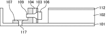
- FIG. It is a side view of the illuminating device of Embodiment 1.
- FIG. It is the top view to which the LED board and fixing plate of the illuminating device of Embodiment 1 were expanded.
- FIG. 10 is a top view illustrating an example of a fixing plate of the lighting apparatus according to the fifth embodiment. It is a front view which shows an example of the stationary plate of the illuminating device of Embodiment 5. It is a top view which shows another example of the fixing plate of the illuminating device of Embodiment 5. It is a front view which shows another example of the fixing plate of the illuminating device of Embodiment 5. It is a top view which shows an example of the fixing plate of the illuminating device of Embodiment 6.
- FIG. 10 is an exploded perspective view of a liquid crystal display device according to a seventh embodiment. It is a top view which shows the external appearance of a liquid crystal display panel (26 type
- substantially includes what can be substantially identified, and when expressed as a numerical value, includes an error within 10% of the whole.
- Embodiment 1 The lighting device of Embodiment 1 can be used as an edge-light type LED backlight that supplies display light to a non-self-luminous panel such as a liquid crystal display panel.
- FIG. 1 is a top view of the lighting apparatus according to the first embodiment, that is, a view when seen from a direction opposite to a direction in which light is emitted from the light guide plate.
- the illumination device of Embodiment 1 includes a backlight chassis (outer frame member) 101, a light guide plate 102, an LED substrate (light emitting element substrate) 103 to which a plurality of LEDs (light emitting elements) are attached, and an LED substrate.
- a fixing plate 107 is provided to fix 103 to the backlight chassis 101.
- a plurality of LED substrates 103 and fixing plates 107 are arranged at positions facing each other with the light guide plate 102 interposed therebetween.
- FIG. 2 is a side view of the lighting apparatus according to the first embodiment.
- An LED 106 is attached on the LED substrate 103.
- a fixing plate 107 is disposed on the back surface of the LED substrate 103, and the LED substrate 103 and the fixing plate 107 are fixed by screws 109 that pass through screw holes (through holes) provided in the LED substrate 103 and the fixing plate 107.
- the heat sink 104 may be arrange
- the fixing plate 107 also has screw holes for fixing to the backlight chassis 101.
- the fixing plate 107 and the backlight chassis 101 have screws (fixing pieces) penetrating through screw holes formed in the fixing plate 107 and the backlight chassis 101, respectively.
- 117 is fixed.
- the fixed plate 107 has at least two surfaces, a surface that contacts the LED substrate 103 via the heat sink 104 and a surface that contacts the backlight chassis 101, and has an L-shaped cross section.
- the fixing plate 107, the heat radiating plate 104, the LED substrate 103, and the LED 106 are attached in this order toward the light guide plate 102.
- a light guide plate 102 is disposed at a position facing the LED 106, and an optical sheet 112 is disposed on the light guide plate 102 for the purpose of increasing luminance.
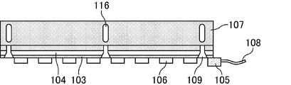
- FIG. 3 is an enlarged front view of the LED substrate of the lighting apparatus according to the first embodiment, that is, a view when viewed from a direction opposite to a direction in which light is emitted from the LED.
- the LEDs 106 are arranged side by side at regular intervals.
- the screw 109 is attached to an arbitrary area between the LEDs 106.
- Connectors 105 are attached to both end regions of the LED substrate 103. From the connector 105, a plurality of lead wires 108 are drawn out including a + wire connected to the anode of the LED 106 and a ⁇ wire connected to the cathode of the LED 106.
- Each lead wire 108 is connected to a power supply board.
- the backlight chassis 101 is a member for housing the LED and the light guide plate, and constitutes an outer frame of the lighting device.
- a material of the backlight chassis 101 it is preferable to use a metal material such as stainless steel, aluminum, or steel plate having high rigidity.
- the light guide plate 102 is generally used for an edge light type backlight, and the light incident on the light guide plate is totally reflected by using a dot pattern or the like printed or injection-molded therein to be emitted as planar light. It is an optical member to be made.
- a material for the light guide plate polycarbonate, acrylic resin, PET (polyethylene terephthalate), or the like is suitable.
- the LED (light emitting element) 106 is a diode that emits, as light, energy generated when electrons and holes are recombined in a depletion layer of a semiconductor pn junction.
- the LED 106 has two kinds of electrodes including an anode and a cathode in addition to the semiconductor element.
- the color type of the LED 106 is not particularly limited, and a plurality of LED colors may be combined to achieve the target color.
- the LED substrate (light emitting element substrate) 103 is a wiring board for mounting the LED, and includes electrodes for supplying a power supply voltage to the LED in addition to each member constituting the LED.
- the LED substrate 103 is not particularly limited as long as it can attach and fix the light emitting element, but a flexible wiring substrate having an insulating surface is preferable.
- the heat radiating plate 104 is a member provided to release heat generated from the LED to the outside, and is a material having high thermal conductivity, for example, aluminum, copper, silver, an alloy thereof, or a ceramic such as aluminum nitride. Materials, steel plates and the like are preferably used.
- the fixing plate 107 is a member for fixing the LED substrate to the backlight chassis, and has at least two surfaces of a surface fixed to the LED substrate and a surface fixed to the backlight chassis. Note that other members may be interposed between the fixed plate and the LED substrate and between the fixed plate and the backlight chassis.
- the means for attaching the LED substrate to the fixing plate is not particularly limited, and may be screwed in addition to the screws as described above, or an adhesive may be used.
- the fixing means for attaching the fixing plate to the backlight chassis is not particularly limited as long as it uses a through hole using a fixing piece, and includes a press-fit pin, an eyelet, and the like in addition to the above-described screwing.
- As the material of the fixing plate it is preferable to use a metal material such as stainless steel or aluminum having high rigidity, like the backlight chassis.
- FIG. 4 is an enlarged top view of the LED substrate and the fixing plate of the lighting apparatus according to the first embodiment.
- a screw hole 116 formed in the fixing plate 107 for fixing the fixing plate 107 and the backlight chassis 101 is not a circle formed in accordance with the diameter of the screw but in a slit shape. It has been extended vertically.
- the screw hole 116 for fixing the fixing plate 107 to the backlight chassis 101 in the first embodiment has a slit shape and is formed long along the direction orthogonal to the light incident surface of the light guide plate 102. In the configuration shown in FIG. 4, both ends of the screw hole 116 are formed in an arc shape.
- the screw hole provided in the backlight chassis 101 does not necessarily have such a slit shape.
- FIG. 5 is a top view showing the position of a screw when the fixing plate in the first embodiment is used in a 26-inch liquid crystal display panel.
- FIG. 6 shows the fixing plate in the first embodiment as a 32-inch liquid crystal display panel. It is a top view which shows the position of the screw when used.
- the screw hole 116 can be screwed at a location further away from the light guide plate 102, and the size of the light guide plate 102 is large.
- screwing can be performed at a position closer to the light guide plate 102 in the screw hole 116.
- the space in which the screw 117 can be attached increases, so that even when the size of the light guide plate 102 is changed, a flexible response is possible.
- Embodiment 2 The illumination device of Embodiment 2 has basically the same configuration as the illumination device of Embodiment 1, but in addition to the configuration of the illumination device of Embodiment 1, when the fixed plate is slid, the illumination device has a light incident surface. On the other hand, it is different from the illumination device of Embodiment 1 in that a fixed plate slide guide for keeping the LED substrate in a parallel position is provided.
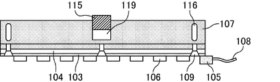
- FIG. 7 is a top view illustrating an example of a fixing plate of the lighting apparatus according to the second embodiment.
- a rectangular guide slit 119 is formed on a part of the surface of the fixed plate 107 that contacts the backlight chassis 101.
- Each side of the guide slit 119 is formed to be perpendicular or parallel to the surface of the LED substrate 103.
- a fixed plate slide guide 115 is formed on a part of the upper surface of the backlight chassis 101.
- the shape of the fixed plate slide guide 115 is substantially the same as the shape of the rectangular guide slit 119 provided on the fixed plate 107, and the fixed plate 107 can be slid along the fixed plate slide guide 115.
- the shape of the guide slit 119 and the fixed plate slide guide 115 is not particularly limited as long as it has a surface parallel to and / or orthogonal to the surface of the fixed plate 107 on the side in contact with the LED substrate 103. When viewed, it is a rectangle, a square, or a trapezoid whose width is widened in the opposite direction to the light guide plate side.
- the fixed plate slide guide 115 may be disposed as a separate member on the backlight chassis 101, or may be integrated with the configuration of the backlight chassis 101.
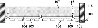
- FIG. 8 is a top view illustrating another example of the fixing plate of the lighting apparatus according to the second embodiment.
- no slit is formed in the fixed plate 107, and two fixed plate slide guides 115 having parallel surfaces along the side surfaces at both ends of the fixed plate 107 are arranged.
- the LED substrate 103 can be kept parallel to the light guide plate 102 when the fixed plate 107 is slid, and the light is parallel to the light guide plate 102. Can be made incident.
- the fixed plate slide guide 115 As a material of the fixed plate slide guide 115, it is preferable to use a metal material such as stainless steel, aluminum, or steel having high rigidity.
- FIG. 9 to 12 show the fixed plate slide guide from the front direction when the fixed plate slide guide is provided along the side surface of the fixed plate of the second embodiment (configuration shown in FIG. 8). It is a front view which shows an example of the time.
- the fixed plate slide guide 115 has an L-shape when viewed from the front.
- the fixed plate slide guide 115 has a substantially U-shape (a shape in which the U-shape is half-turned) when viewed from the front.
- the fixed plate slide guide 115 has a substantially U-shape (a shape in which the U-shape is half-turned) when viewed from the front.
- FIG. 11 the fixed plate slide guide 115 has a substantially U-shape (a shape in which the U-shape is half-turned) when viewed from the front.
- the fixed plate slide guide 115 may be constituted by a part of the backlight chassis 101.
- the fixed plate slide guide 115 may be configured by using the ribs of the backlight chassis 101, thereby reducing the number of members.
- the fixed plate slide guide 115 has a surface parallel to the outer surface of the fixed plate 107.
- a substantially U-shape, a substantially U-shape, or a square pipe shape as described above is particularly preferable.
- the lighting device of the third embodiment has basically the same configuration as the lighting devices of the first and second embodiments, but the size of the screw holes provided in the fixing plate and the backlight chassis substantially matches the size of the screws. And the difference from the illumination device of the first embodiment in that two or more screw holes are provided in a row instead of one for each fixing portion.
- FIG. 13 is a top view illustrating an example of a fixing plate of the lighting apparatus according to the third embodiment.
- the screw holes 116 are formed in a plurality of rows. More specifically, each screw hole 116 is formed in a total of three rows, two each in a direction perpendicular to the surface of the fixed plate 107 facing the light guide plate. Further, the lateral positions of the plurality of screw holes that respectively form a line match each other. That is, the plurality of screw holes provided in the third embodiment are also formed so as to form two rows parallel to the surface of the fixed plate 107 facing the light guide plate.
- FIG. 14 is a top view illustrating another example of the fixing plate of the lighting apparatus according to the third embodiment.
- the plurality of screw holes 116 each forming a row are formed in three rows, two each in a direction orthogonal to the surface of the fixed plate 107 facing the light guide plate. Yes.
- one additional screw hole 116 is also provided in the lateral position adjacent to the screw holes 116 forming these rows, and each of the plurality of screw holes 116 forming the rows is provided.
- the horizontal positions are the same. That is, in this configuration, the plurality of screw holes are formed in three rows parallel to the surface of the fixed plate 107 facing the light guide plate, and each screw region is a candidate for mounting a screw. Three screw attachable areas are formed.
- each screw hole 116 has a circular shape substantially the same as the shape of the penetrating portion of the screw, and the size is also substantially the same. According to the third embodiment, since the number of candidate locations where screws can be attached increases, it is possible to cope with changes in the size of the light guide plate. In addition, since the lateral positions of the plurality of screw holes that respectively form a row are also adjusted, light can be incident in parallel to the light guide plate.
- Embodiment 4 The lighting device of the fourth embodiment has basically the same configuration as that of the lighting device of the first embodiment, but the side surface shape of the fixing plate is not an L-shaped cross section, but a square pipe type (B) The illumination device of the first embodiment is different from that of the first embodiment.
- FIG. 15 is a side view of a fixing plate of the lighting apparatus according to the fourth embodiment.
- the inside of the fixed plate is perforated (space).
- the exposed area of the heat radiating plate 104 that is, the heat radiating area increases, so that it is generated in the LED 106 and is fixed to the fixing plate 107 via the LED substrate 103 and the heat radiating plate 104.
- the heat dissipation effect of the heat transmitted to can be further improved.
- Embodiment 5 The illumination device of the fifth embodiment has basically the same configuration as the illumination device of the second embodiment, but a through hole is not formed in the fixed plate in the region where the fixed plate and the fixed plate slide guide overlap. , Which is different from the illumination device of the second embodiment in that a hollow that is partially penetrated is formed.
- FIG. 16 and 17 are diagrams illustrating an example of a fixing plate of the lighting apparatus according to the fifth embodiment.
- FIG. 16 is a top view and FIG. 17 is a front view.
- a slit that penetrates the fixed plate 107 is not formed in a region overlapping with the fixed plate slide guide 115 (a region surrounded by a dotted line in the drawing).
- the slits provided in the fixing plate 107 shown in FIG. 16 are screw holes 116 for fixing the backlight chassis and the fixing plate 107.
- a depression (concave portion) having substantially the same shape and height as the shape of the stationary plate slide guide 115 is formed in a part of the stationary plate 107, thereby fixing the stationary plate 107. It is possible to slide in a shape along the shape of the plate slide guide 115.
- the depression is located in the middle of the two screw holes 116 for the backlight chassis 101 formed in the fixed plate 107.
- FIGS. 18 and 19 are diagrams showing another example of the fixing plate of the lighting apparatus according to the fifth embodiment.
- FIG. 18 is a top view and FIG. 19 is a front view.
- the depressions may be formed in regions overlapping with both ends of the fixing plate 107.
- the mutually opposing surfaces of the two fixed plate slide guides 115 are parallel to each other.
- the recess may be formed only in a region overlapping with one end of the fixed plate 107.
- the LED substrate can be kept parallel to the light guide plate when the fixed plate 107 is slid.
- light can be incident on the light guide plate in parallel.
- Embodiment 6 The illumination device of the sixth embodiment has basically the same configuration as the illumination device of the second embodiment, but differs from the illumination device of the second embodiment in that a fixed plate slide guide is provided for the fixed plate.
- FIG. 20 and 21 are diagrams illustrating an example of a fixing plate of the lighting apparatus according to the sixth embodiment.
- FIG. 20 is a top view and FIG. 21 is a front view.
- a slit that penetrates the fixed plate is not formed in a region overlapping with the fixed plate slide guide 115.
- a slit provided in the fixed plate 107 shown in FIG. 20 is a screw hole 116 for fixing the backlight chassis and the fixed plate 107.
- a fixed plate slide guide 115 is attached to the bottom surface of the fixed plate 107, and a slit having substantially the same shape as the fixed plate slide guide 115 is formed on the backlight chassis 101. ing.
- the fixed plate 107 can be slid along the shape of the fixed plate slide guide 115.
- Each of the fixed plate slide guides 115 is provided in a region slightly inward from both end surfaces of the fixed plate 107. At this time, the surfaces of the two fixed plate slide guides 115 facing each other are preferably parallel.
- FIG. 22 is a front view illustrating another example of the fixing plate of the lighting apparatus according to the sixth embodiment.
- a part of the bottom surface of the fixing plate 107 may be protruded as in the configuration shown in FIG. That is, the fixed plate slide guide 115 may be formed integrally with the fixed plate.
- FIG. 23 is a top view in which a backlight chassis is further added to FIG.
- the backlight chassis 101 has a slide groove 118 in a region overlapping with the fixed plate slide guide 115 (a region surrounded by a dotted line in the drawing).
- the slide groove 118 is formed in a vertically long slit shape, and its end is formed in an arc shape.
- the slit provided in the backlight chassis 101 is not limited to what penetrates the backlight chassis 101, and may form a recess with a certain depth.
- the fixed plate slide guide is provided in a part of the fixed plate, and the slide groove is provided in the backlight chassis, so that the LED substrate is kept parallel to the light guide plate when the fixed plate is slid.
- light can be incident in parallel to the light guide plate.
- Embodiment 7 is an embodiment in which the lighting device of the present invention is applied to a liquid crystal display device.
- the type of the liquid crystal display device is not particularly limited as long as it is a type that uses backlight light as display light (for example, transmissive type and transflective type).
- FIG. 24 is an exploded perspective view of the liquid crystal display device according to the seventh embodiment.
- the liquid crystal display device according to the seventh embodiment includes a backlight chassis 101, a light guide plate 102, an optical sheet 112, a liquid crystal display panel 113, and a bezel 114 in this order from the back side toward the observation surface side.
- the lighting device including the backlight chassis 101 and the light guide plate 102 is any one of the lighting devices described in the first to sixth embodiments.
- a plurality of optical sheets 112 are arranged on the light guide plate 102.
- various sheets such as a prism sheet that refracts and reflects light to collect light to improve luminance and a diffusion sheet that diffuses light and prevents display unevenness are used.
- a liquid crystal display panel 113 is disposed on the optical sheet 112.
- the liquid crystal display panel 113 includes a liquid crystal layer and a pair of substrates that seal the liquid crystal layer as constituent elements, and transmits and blocks light (display on / off) by controlling the orientation of birefringent liquid crystal molecules. And off) can be controlled.
- the liquid crystal display device of Embodiment 7 has the illumination device of the present invention, it can flexibly cope with a design change of other members.
Landscapes
- Physics & Mathematics (AREA)
- Nonlinear Science (AREA)
- Mathematical Physics (AREA)
- Chemical & Material Sciences (AREA)
- Crystallography & Structural Chemistry (AREA)
- General Physics & Mathematics (AREA)
- Optics & Photonics (AREA)
- Planar Illumination Modules (AREA)
Abstract
本発明は、他の部材の設計の変更があったときでも柔軟に対応することが可能な構造をもつ照明装置を提供する。本発明の照明装置は、発光素子と、上記発光素子が取り付けられた発光素子基板と、上記発光素子基板を収納する外枠部材と、上記発光素子基板と該外枠部材との間に配置され、かつ上記発光素子基板及び上記外枠部材の双方と固定された固定板とを有する照明装置であって、上記固定板には、スリット状の貫通孔、又は、少なくとも二列をなして並んだ複数の貫通孔が形成されており、上記固定板と該外枠部材とは、上記スリット状の貫通孔、又は、上記少なくとも二列をなして並んだ複数の貫通孔の少なくとも一つに挿入された固定片によって互いに固定されている照明装置である。
Description
本発明は、照明装置及び液晶表示装置に関する。より詳しくは、発光素子を備えるエッジライト型の照明装置、及び、該照明装置を備える液晶表示装置に関する。
液晶表示装置等の非自発光型の表示装置には、表示を行うための光の供給源が必要である。太陽光を表示に利用することも可能であるが、例えば、ワードプロセッサ、ノート型パーソナルコンピュータ、車載用パネル等の主に室内で使用される表示装置、又は、屋外で使用されるが常に一定量の明るさが要求される表示装置の内部にはバックライトが備え付けられる。
表示装置に用いられるバックライトの形態としては、エッジライト型及び直下型が一般的である。小型の画面を備える表示装置では、少ない数の光源により低消費電力で表示を行うことが可能であり、かつ薄型化にも適したエッジライト型が好適に用いられる(例えば、特許文献1参照。)。光源としては、線光源として冷陰極管(CCFL:Cold Cathode Fluorescent Lamp)が、点光源として発光ダイオード(LED:Light Emitting Diode)が多く利用されており、特にLEDは低消費電力化が可能であることから、近年急速に普及している。
バックライトを構成する部材としては、光源の他、反射フィルム、拡散シート、プリズムシート等が挙げられ、エッジライト型においては、更に導光板が設けられる。導光板は、通常、内部に印刷又は射出成型によってパターン形状が形成された無色透明の部材が多く用いられる。エッジライト型のバックライトでは、導光板の主面が表示パネルの主面と対向するようにして配置され、かつ導光板の側方に、導光板の入光面に向かって光を出射する光源が配置される。
LEDが光源として用いられる場合は、導光板の入光面と対向するアレイ基板に対して複数のLEDが横並びに実装される。以下、LEDが実装されるアレイ基板を「LED基板」ともいう。そして、各LEDから出射された直進性を有する光は、導光板の内部で反射、屈折及び拡散され、主面から面状の光となって出射される。各LEDに対しては、駆動用の電圧を供給するための電源回路を設ける必要があり、各LEDは、LED基板に取り付けられたコネクタ及び/又はリード線を介して、それぞれ電源基板と電気的に接続される。
このようなLED基板を照明装置の内部に固定する方法としては、LED基板の裏側に固定板を貼り合わせ、更に、その固定板を照明装置の外枠を構成する部材にネジ止め等で固定する方法が考えられる。
しかしながら、このような固定を行うためには、固定板及び照明装置の外枠を構成する部材(以下、外枠部材ともいう。)のそれぞれにあらかじめ貫通孔を開けておく等の処理が必要であり、例えば、貫通孔の形成後、導光板又はLEDの輝度スペックが変更になった場合にはLED基板と導光板との距離を変更しなければならず、その場合、照明装置の外枠を構成する部材に追加で貫通孔を設ける工程を行う必要が出てくる等、リワークに多大な労力が費やされる。
本発明は、上記現状に鑑みてなされたものであり、他の部材の設計の変更があったときでも柔軟に対応することが可能な構造をもつ照明装置を提供することを目的とするものである。
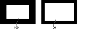
本発明者は、設計の変更に柔軟に対応することができるLED照明装置の構造について種々検討したところ、以下のような場合に、固定板の位置が変更になる点に着目した。図25は、液晶表示パネル(26型及び32型)の外観を示す上面図である。また、図26は、液晶表示パネル(26型及び32型)下に配置されたバックライトの構造を示す上面図である。バックライトの外枠を構成するバックライトシャーシ501の内部に、導光板502、LED基板503、及び、固定板507が収納されている。LED基板503の導光板502と対向する面上には、複数のLEDが取り付けられている。図25及び図26に示すように、液晶表示パネルの表示領域100の大きさによって、導光板502の大きさは変更される。導光板502が変更になる場合、図26に示すように、LED基板503及びその固定板507のサイズについて変更を行う必要はなく、LED基板503及びその固定板507の位置も、より後ろ側にずらして配置することで対応が可能である。
本発明者はこの点に着目し、LED基板を固定する固定板に対して形成される、固定板を外枠部材に取り付けるための貫通孔に工夫を加えることで、上記課題が解決されることを見いだした。具体的には、貫通孔を従来のような固定ネジ(ビス)とほぼ同様の大きさを有する円形とするのではなく、貫通孔をスリット状とする、又は、固定ネジ(ビス)とほぼ同様の大きさを有する円形の貫通孔を一つではなく複数、かつ列をなして設けることで、LED基板及び固定板をスライドさせたとしても、固定板と外枠部材との固定が可能となる複数の領域が形成されるので、設計に柔軟性を持たせることができることを見いだした。こうして、本発明者は、上記課題をみごとに解決することができることに想到し、本発明に到達したものである。
すなわち、本発明は、発光素子と、上記発光素子が取り付けられた発光素子基板と、上記発光素子基板を収納する外枠部材と、上記発光素子基板と該外枠部材との間に配置され、かつ上記発光素子基板及び上記外枠部材の双方と固定された固定板とを有する照明装置であって、上記固定板には、スリット状の貫通孔、又は、少なくとも二列をなして並んだ複数の貫通孔が形成されており、上記固定板と上記外枠部材とは、上記スリット状の貫通孔、又は、上記少なくとも二列をなして並んだ複数の貫通孔の少なくとも一つに挿入された固定片によって互いに固定されている照明装置である。
本発明において発光素子は、発光素子基板に取り付けられ、その発光素子基板が固定板を介して照明装置の外枠を構成する部材に取り付けられることで、その位置が固定される。こうして、例えば、導光板に対して均一な光を出射することが容易となる。
本発明においては固定板に貫通孔が設けられており、この貫通孔を利用してネジ止め、ビス止め等を行うことで固定板と外枠部材とは固定される。また、上記貫通孔は、スリット状とする、又は、複数個設けられているので、他の部材の設計の変更に応じて柔軟に固定位置を変えることが可能である。
本発明の照明装置の構成としては、このような構成要素を必須として形成されるものである限り、その他の構成要素により特に限定されるものではない。
本発明の照明装置における好ましい形態について、以下に詳しく説明する。
上記スリットの幅は、上記固定片の径と略同一であり、上記スリットの長さは、上記固定片の径よりも大きいことが好ましい。これにより、上記スリットに、通常の固定片を通して固定板と外枠部材との固定を可能にしつつ、他の部材に設計に変更があったとしても、柔軟に対応することができる。
上記少なくとも二列をなして並んだ複数の貫通孔の径は、上記固定ネジの径と略同一であることが好ましい。これにより、上記スリットに、通常の固定片を通して固定板と外枠部材との固定を可能にしつつ、他の部材に設計に変更があったとしても、柔軟に対応することができる。
上記照明装置は、上記発光素子基板と対向する位置に入光面を有する導光板を有し、上記スリット状の貫通孔は、上記導光板の入光面と直交する方向に沿って長く形成されていることが好ましい。これにより、導光板のサイズ変更があったとしても、単に固定片の取り付け位置を変えるのみで対応することができ、新たに外枠部材等に加工を行う手間を省くことができる。
上記照明装置は、上記発光素子基板と対向する位置に入光面を有する導光板を有し、上記少なくとも二列をなして並んだ複数の貫通孔は、固定板の導光板と対向する面に対して直交する方向に並んで形成されていることが好ましい。これにより、導光板のサイズ変更があったとしても、単に固定片の取り付け位置を変えるのみで対応することができ、新たに外枠部材等に加工を行う手間を省くことができる。
上記照明装置は、上記発光素子基板と対向する位置に入光面を有する導光板を有し、上記少なくとも二列をなして並んだ複数の貫通孔は、固定板の導光板と対向する面に対して平行に並んで形成されていることが好ましい。これにより、導光板の入光面に対してLED基板の面を平行に位置取りすることができ、導光板に対して平行に光を入射させることができるようになる。
上記固定板の形状は、中央が刳り貫かれたパイプ型であることが好ましい。これにより、固定板の外部への露出面積が増えるので、よりLEDから発生した熱を外部に放出しやすくなり、発光素子の特性劣化を防ぐことができる。
上記固定板の形状は、断面L字型の壁形状であることが好ましい。これにより、互いに異なる二つの面をもつ部材を固定しやすくなる。
上記照明装置は、更に、固定板スライドガイドを有し、上記固定板スライドガイドは、発光素子基板の面と平行及び/又は直交する面を有することが好ましい。これにより、固定板をスライドさせる際に導光板に対してLED基板が平行な位置取りを保つことができ、導光板に対して平行に光を入射させやすくなる。
上記固定板の一部には、切り欠き部が形成されており、上記固定板スライドガイドは、上記固定板の切り欠き面に沿った形状を有することが好ましい。これにより、固定板スライドガイドと固定板との位置合わせを容易に行うことができる。
上記外枠部材の一部には、切り欠き部が形成されており、上記固定板スライドガイドは、上記外枠部材の切り欠き面に沿った形状を有することが好ましい。これにより、固定板スライドガイドと外枠部材との位置合わせを容易に行うことができる。
上記切り欠き部は、上記固定板の一部に開口を設ける切り落としによって形成された部位であることが好ましい。固定板スライドガイドと重ね合わせる部材の一部を貫通するような加工が好適である場合には、これにより、固定板又は外枠部材に対して固定板スライドガイドの形状に沿った形状を得ることができる。
上記切り欠き部は、上記固定板の一部に窪みを設ける切り落としによって形成された部位であることが好ましい。固定板スライドガイドと重ね合わせる部材の一部が貫通するような加工が不適切である場合には、これにより、固定板又は外枠部材に対して固定板スライドガイドの形状に沿った形状を得ることができる。
上記切り欠き部は、上記固定板の発光素子基板の面と対向する面の縦方向の二等分領域を含むことが好ましい。固定板の末端領域に切り欠き部を設けることが不適切である場合には、これにより、固定板スライドガイドの形状に沿った形状を得ることができる。
上記切り欠き部は、上記固定板の少なくとも一方の末端領域を含むことが好ましい。固定板の内部領域に切り欠き部を設けることが不適切である場合には、これにより、固定板スライドガイドの形状に沿った形状を得ることができる。
上記固定板スライドガイドは、上記固定板の両端面に沿った形状を有することが好ましい。これにより、固定板に対して加工を行わなくとも、固定板スライドガイドの形状に沿った形状を得ることができる。
上記固定板スライドガイドは、上記外枠部材上に取り付けられている、又は、上記外枠部材と一体形成されていることが好ましい。LEDの光軸が導光板に対して確実に垂直に入射するように固定したい場合に、これらのいずれかの形態を適宜選択することが好適である。
上記固定板スライドガイドは、上記固定板上に取り付けられている、又は、上記固定板と一体形成されていることが好ましい。LEDの光軸が導光板に対して確実に垂直に入射するように固定したい場合に、これらのいずれかの形態を適宜選択することが好適である。
本発明はまた、上記本発明の照明装置を備える液晶表示装置でもある。本発明の照明装置は、液晶表示装置のバックライトとして好適に用いられるものであり、これにより、他の部材の設計変更があったとしても、柔軟に対応することができる。
本発明の照明装置によれば、LED基板と外枠部材との間に配置される固定板を外枠部材に取り付けるための貫通孔に工夫がなされているので、他の部材の設計変更があったとしても、柔軟に対応することができる。
以下に実施形態を掲げ、本発明について図面を参照して更に詳細に説明するが、本発明はこれらの実施形態のみに限定されるものではない。
本明細書において「略」とは、実質的に同一視することができるものを含むものとし、数値として表される場合には、全体に対して10%以内の誤差を含む。
実施形態1
実施形態1の照明装置は、液晶表示パネル等の非自発光型のパネルに対して表示光を供給するエッジライト型のLEDバックライトとして用いることができる。
実施形態1の照明装置は、液晶表示パネル等の非自発光型のパネルに対して表示光を供給するエッジライト型のLEDバックライトとして用いることができる。
図1は、実施形態1の照明装置の上面図、すなわち、導光板から光が出射される方向と相対する方向から見たときの図である。図1に示すように実施形態1の照明装置は、バックライトシャーシ(外枠部材)101、導光板102、複数のLED(発光素子)を取り付けるLED基板(発光素子基板)103、及び、LED基板103をバックライトシャーシ101に固定する固定板107を有する。LED基板103及び固定板107は、導光板102を挟んで互いに対向する位置に複数配置されている。
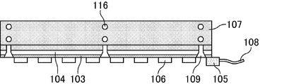
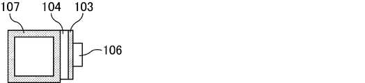
図2は、実施形態1の照明装置の側面図である。LED基板103上には、LED106が取り付けられている。LED基板103の背面には固定板107が配置されており、LED基板103及び固定板107に設けられたビス穴(貫通孔)を貫通するビス109によって、LED基板103と固定板107とは固定されている。なお、LED基板103と固定板107との間には図2に示すように放熱板104が配置されていてもよく、その場合には、放熱板104に対してもビス穴が設けられる。また、固定板107は、バックライトシャーシ101と固定するためのビス穴も有しており、固定板107とバックライトシャーシと101は、それぞれに形成されたビス穴を貫通するビス(固定片)117によって固定されている。固定板107は、放熱板104を介してLED基板103と接触する面と、バックライトシャーシ101と接触する面との少なくとも二つの面を有し、断面L字状の形状を有する。実施形態1では、導光板102に向かって固定板107、放熱板104、LED基板103及びLED106がこの順に取り付けられる。LED106と対向する位置には導光板102が配置され、導光板102上には、輝度を高める等の目的で光学シート112が配置されている。
図3は、実施形態1の照明装置のLED基板を拡大した正面図、すなわち、LEDから光が出射される方向と相対する方向から見たときの図である。LED106は、それぞれが一定の間隔を空けて横並びに配置されている。ビス109は、LED106間の任意の領域に取り付けられている。LED基板103の両末端領域には、コネクタ105が取り付けられている。コネクタ105からは、LED106の陽極と接続された+線、及び、LED106の陰極と接続された-線からなる複数のリード線108が引き出されている。各リード線108は電源基板と接続されている。
バックライトシャーシ101は、LEDや導光板を収納するための部材であり、照明装置の外枠を構成する。バックライトシャーシ101の材料としては、剛直性の高いステンレス、アルミニウム、鋼板等の金属材料を用いることが好適である。
導光板102は、一般的にエッジライト型のバックライトに用いられ、導光板内に入射した光を内部に印刷又は射出成型されたドットパターン等を用いて全反射させ、面状の光として出射させる光学部材である。導光板の材料としては、ポリカーボネート、アクリル樹脂、PET(ポリエチレンテレフタレート)等が好適である。
LED(発光素子)106は、半導体のpn接合の空乏層で電子と正孔とが再結合するときに発生するエネルギーを光として放出するダイオードである。LED106は、半導体素子のほかに、陽極及び陰極からなる二種類の電極を有している。LED106の色の種類は特に限定されず、目的の色を達成するために複数のLEDの色を組み合わせてもよい。
LED基板(発光素子基板)103は、LEDを実装するための配線板であり、LEDを構成する各部材に加え、LEDに対して電源電圧を供給するための電極を有する。LED基板103は、発光素子を取り付け、固定することができる基板であれば特に限定されないが、表面が絶縁性を有するフレキシブル配線基板が好ましい。
放熱板104は、LEDから発生した熱を外部に逃がすために設けられる部材であり、熱伝導性が高い材料、例えば、アルミニウム、銅、銀、若しくは、これらの合金、又は、窒化アルミニウム等のセラミック材料、鋼板等が好適に用いられる。
固定板107は、LED基板をバックライトシャーシに固定するための部材であり、LED基板に固定される面と、バックライトシャーシに固定される面との少なくとも2つの面を有する。なお、固定板とLED基板との間、及び、固定板とバックライトシャーシとの間には、他の部材が介在していてもよい。固定板に対するLED基板の取り付け手段は、特に限定されず、上述のようなビス止めのほか、ネジ止めとしてもよいし、接着剤を用いてもよい。バックライトシャーシに対する固定板の取り付け手段は、固定片を用いて貫通孔を利用するものであれば特に限定されず、上述のようなビス止めのほか、圧入ピン、ハトメ等が挙げられる。固定板の材料としては、バックライトシャーシと同様、剛直性の高いステンレス、アルミニウム等の金属材料を用いることが好適である。
図4は、実施形態1の照明装置のLED基板及び固定板を拡大した上面図である。図4に示すように、固定板107とバックライトシャーシ101とを固定するために固定板107に対して形成されたビス穴116はビスの径にあわせて形成された円形ではなく、スリット状に縦方向に拡張されている。言い換えれば、実施形態1において固定板107をバックライトシャーシ101に固定するためのビス穴116は、スリット状であり、導光板102の入光面と直交する方向に沿って長く形成されている。また、図4に示す構成では、ビス穴116の両末端は円弧状に形成されている。なお、バックライトシャーシ101に設けるビス穴は必ずしもこのようなスリット形状を有している必要はない。図5は、実施形態1における固定板を26型の液晶表示パネルに用いたときのビスの位置を示す上面図であり、図6は、実施形態1における固定板を32型の液晶表示パネルに用いたときのビスの位置を示す上面図である。導光板102のサイズが小さい場合には、図5に示すように、ビス穴116のうち、導光板102からより離れた場所にビス止めを行うことができ、導光板102のサイズが大きい場合には、図6に示すように、ビス穴116のうち、より導光板102に近い場所にビス止めを行うことができる。このように、実施形態1によれば、ビス117が取り付け可能なスペースが増えるので、導光板102のサイズに変更があったときでも柔軟な対応が可能である。
実施形態2
実施形態2の照明装置は、実施形態1の照明装置と基本的に同様の構成を有するが、実施形態1の照明装置の構成に更に、固定板をスライドさせる際に導光板の入光面に対してLED基板が平行な位置取りを保つようにするための固定板スライドガイドが設けられている点で実施形態1の照明装置と相違する。
実施形態2の照明装置は、実施形態1の照明装置と基本的に同様の構成を有するが、実施形態1の照明装置の構成に更に、固定板をスライドさせる際に導光板の入光面に対してLED基板が平行な位置取りを保つようにするための固定板スライドガイドが設けられている点で実施形態1の照明装置と相違する。
図7は、実施形態2の照明装置の固定板の一例を示す上面図である。図7に示すように、固定板107のバックライトシャーシ101と接する面の一部には、矩形のガイドスリット119が形成されている。ガイドスリット119の各辺はLED基板103面に対して垂直又は平行となるように形成されている。また、実施形態2においては、バックライトシャーシ101の上面の一部において、固定板スライドガイド115が形成されている。固定板スライドガイド115の形状は、固定板107に設けられた矩形のガイドスリット119の形状と略同一であり、固定板スライドガイド115に沿って固定板107をスライドさせることができる。
実施形態2においてガイドスリット119及び固定板スライドガイド115の形状は、固定板107のLED基板103と接する側の面と平行及び/又は直交する面を有する限り特に限定されないが、好ましくは、上から見たときに長方形、正方形、又は、導光板側と反対方向に幅が広がった台形である。固定板スライドガイド115は、バックライトシャーシ101上に別個の部材として配置されていてもよいし、バックライトシャーシ101の構成と一体化されていてもよい。
図8は、実施形態2の照明装置の固定板の他の一例を示す上面図である。図8の構成では、固定板107にスリットは形成されておらず、固定板107の両端の側面に沿って平行な面を持つ二つの固定板スライドガイド115が配置されている。
このような固定板スライドガイド115を設けることで、固定板107をスライドさせる際に導光板102に対してLED基板103が平行な位置取りを保つことができ、導光板102に対して平行に光を入射させることができるようになる。
固定板スライドガイド115の材質としては、剛直性の高いステンレス、アルミニウム、鋼材等の金属材料を用いることが好適である。
図9~12は、実施形態2の固定板のうち、固定板の側面に沿って固定板スライドガイドを設けた場合(図8で示される構成)の、固定板スライドガイドを正面方向から見たときの一例を示す正面図である。図9に示す構成では、固定板スライドガイド115は正面方向から見たときにL字型の形状を有する。図10に示す構成では、固定板スライドガイド115は正面方向から見たときに略U字型(コの字が半転した形状)の形状を有する。図11に示す構成では、固定板スライドガイド115は正面方向から見たときに略コの字型(U字型が半転した形状)の形状を有する。また、図12に示されるように、固定板スライドガイド115を新たに設ける代わりに、バックライトシャーシ101の一部を延出して固定板スライドガイドに相当する構造を形成してもよい。すなわち、固定板スライドガイド115はバックライトシャーシ101の一部で構成されていてもよい。このように上記固定板スライドガイド115はバックライトシャーシ101のリブを利用して構成されていてもよく、これにより、部材の数を減らすことができる。
固定板107の両端の側面に沿って平行な面を持つ二つの固定板スライドガイド115が配置されるタイプの構成では、上記固定板スライドガイド115は固定板107の外面に平行な面を有する限り特に限定されないが、上記のような略U字型、略コの字型、又は、四角パイプ型の形状が特に好ましい。
実施形態3
実施形態3の照明装置は、実施形態1及び2の照明装置と基本的に同様の構成を有するが、固定板及びバックライトシャーシに設けられるビス穴の大きさがビスの大きさとほぼ一致している点、及び、一つの固定部位につきビス穴が一つではなく列をなして二つ以上設けられている点で実施形態1の照明装置と相違する。
実施形態3の照明装置は、実施形態1及び2の照明装置と基本的に同様の構成を有するが、固定板及びバックライトシャーシに設けられるビス穴の大きさがビスの大きさとほぼ一致している点、及び、一つの固定部位につきビス穴が一つではなく列をなして二つ以上設けられている点で実施形態1の照明装置と相違する。
図13は、実施形態3の照明装置の固定板の一例を示す上面図である。図13に示す構成では、ビス穴116は、複数の列をなすように形成されている。より具体的には、各ビス穴116は、固定板107の導光板と対向する面に対して直交する方向にそれぞれ2つずつ、計3つの列をなして形成されている。また、それぞれ列をなす複数のビス穴の横位置は、それぞれ一致している。すなわち、実施形態3において設けられる複数のビス穴は、固定板107の導光板と対向する面に対して平行に2つの列をなすようにも形成されている。
図14は、実施形態3の照明装置の固定板の他の一例を示す上面図である。図14に示す構成においても、それぞれ列をなす複数のビス穴116は、固定板107の導光板と対向する面に対して直交する方向にそれぞれ2つずつ、3つの列をなして形成されている。ただし、図14に示す構成では更に、これら列をなすビス穴116に近接する横位置にも、それぞれ一つずつ追加でビス穴116が設けられており、それぞれ列をなす複数のビス穴116の横位置は、それぞれ一致している。すなわち、本構成では、複数のビス穴は、固定板107の導光板と対向する面に対して平行に3つの列をなすように形成されており、ビスが取り付けられる候補となる一つの領域につき、3つのビス取り付け可能領域が形成される。
実施形態3では、各ビス穴116は、ビスの貫通部分の形状と略同一の円形を有し、かつ大きさも略同一である。実施形態3によれば、ビスが取り付け可能な場所の候補の数が増えるので、導光板のサイズに変更があったときでも対応が可能である。また、それぞれ列をなす複数のビス穴の横位置も調整されているので、導光板に対して平行に光を入射させることができる。
実施形態4
実施形態4の照明装置は、実施形態1の照明装置と基本的に同様の構成を有するが、固定板の側面形状が断面L字型ではなく、中央が刳り貫かれた四角パイプ型(ロの字型)である点で実施形態1の照明装置と相違する。
実施形態4の照明装置は、実施形態1の照明装置と基本的に同様の構成を有するが、固定板の側面形状が断面L字型ではなく、中央が刳り貫かれた四角パイプ型(ロの字型)である点で実施形態1の照明装置と相違する。
図15は、実施形態4の照明装置の固定板の側面図である。図15に示すように、固定板の内部は穴開き(空間)になっている。固定板107がこのような穴開き形状を有していると、放熱板104の露出面積、すなわち、放熱面積が増えるため、LED106で発生し、LED基板103及び放熱板104を介して固定板107に伝わってきた熱の放熱効果をより向上させることができる。
実施形態5
実施形態5の照明装置は、実施形態2の照明装置と基本的に同様の構成を有するが、固定板と固定板スライドガイドとが重なる領域において、固定板に貫通孔が形成されるのではなく、一部を刳り貫いた窪みが形成される点で実施形態2の照明装置と相違する。
実施形態5の照明装置は、実施形態2の照明装置と基本的に同様の構成を有するが、固定板と固定板スライドガイドとが重なる領域において、固定板に貫通孔が形成されるのではなく、一部を刳り貫いた窪みが形成される点で実施形態2の照明装置と相違する。
図16及び図17は、実施形態5の照明装置の固定板の一例を示す図であり、図16は上面図を、図17は正面図をそれぞれ表している。図16に示すように、固定板スライドガイド115と重なる領域(図中の点線で囲まれる領域)には固定板107を貫通するスリットが形成されていない。図16に示される固定板107に設けられたスリットは、バックライトシャーシと固定板107とを固定するためのビス穴116である。一方、図17に示すように、固定板107の一部には固定板スライドガイド115の形状とほぼ同じ形状及び高さの窪み(凹部)が形成されており、これにより、固定板107を固定板スライドガイド115の形状に沿った形でスライドさせることが可能となる。上記窪みは、固定板107に形成されたバックライトシャーシ101に対する2つのビス穴116の中間に位置している。
図18及び図19は、実施形態5の照明装置の固定板の他の一例を示す図であり、図18は上面図を、図19は正面図をそれぞれ表している。実施形態5では、図18及び図19で示される構成のように、上記窪みを固定板107の両端と重なる領域にそれぞれ形成してもよい。このとき、2つの固定板スライドガイド115の互いに対向する面は、互いに平行であることが好ましい。また、上記窪みを固定板107の一方の端部と重なる領域だけに形成してもよい。
このように固定板107の一部に固定板スライドガイド115の形状に合わせた加工を行うことで、固定板107をスライドさせる際に導光板に対してLED基板が平行な位置取りを保つことができ、導光板に対して平行に光を入射させることができるようになる。
実施形態6
実施形態6の照明装置は、実施形態2の照明装置と基本的に同様の構成を有するが、固定板スライドガイドが固定板に対して設けられる点で実施形態2の照明装置と相違する。
実施形態6の照明装置は、実施形態2の照明装置と基本的に同様の構成を有するが、固定板スライドガイドが固定板に対して設けられる点で実施形態2の照明装置と相違する。
図20及び図21は、実施形態6の照明装置の固定板の一例を示す図であり、図20は上面図を、図21は正面図をそれぞれ表している。図20に示すように、固定板スライドガイド115と重なる領域には固定板を貫通するスリットが形成されていない。図20に示される固定板107に設けられたスリットは、バックライトシャーシと固定板107とを固定するためのビス穴116である。一方、図21に示すように、固定板107の底面には固定板スライドガイド115が付属されており、バックライトシャーシ101に対して固定板スライドガイド115の形状とほぼ同じ形状のスリットが形成されている。
これにより、固定板107を固定板スライドガイド115の形状に沿った形でスライドさせることが可能となる。上記固定板スライドガイド115は、固定板107の両端面から少し内側に入った領域にそれぞれ一つずつ設けられている。このとき、2つの固定板スライドガイド115の互いに対向する面は、平行であることが好ましい。
図22は、実施形態6の照明装置の固定板の他の一例を示す正面図である。実施形態6では、図22で示される構成のように、固定板107の底面の一部を突出させる形で形成してもよい。すなわち、上記固定板スライドガイド115を固定板と一体化した形で形成してもよい。
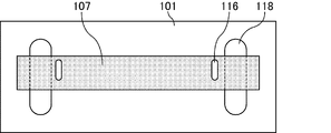
図23は、図20に対し、更にバックライトシャーシを追加した上面図である。バックライトシャーシ101は、固定板スライドガイド115と重なる領域(図中の点線で囲まれる領域)に、スライド溝118を有する。スライド溝118は、縦長のスリット状に形成されており、末端は円弧状になるように形成されている。なお、バックライトシャーシ101に設けられるスリットは、バックライトシャーシ101を貫通するものに限定されず、一定深さの窪みを形成するものであってもよい。
このように固定板の一部に固定板スライドガイドを設け、かつバックライトシャーシにスライド溝を設けることで、固定板をスライドさせる際に導光板に対してLED基板が平行な位置取りを保つことができ、導光板に対して平行に光を入射させることができるようになる。
以上、実施形態1~6について説明したが、これらは技術的に矛盾しない限り、それぞれの特徴を互いに組み合わせて用いることができる。
実施形態7
実施形態7は、本発明の照明装置を液晶表示装置に適用した実施形態である。液晶表示装置の種類としては、バックライト光を表示光として用いるタイプ(例えば、透過型及び半透過型)である限り、特に限定されない。
実施形態7は、本発明の照明装置を液晶表示装置に適用した実施形態である。液晶表示装置の種類としては、バックライト光を表示光として用いるタイプ(例えば、透過型及び半透過型)である限り、特に限定されない。
図24は、実施形態7の液晶表示装置の分解斜視図である。実施形態7の液晶表示装置は、背面側から観察面側に向かって、バックライトシャーシ101、導光板102、光学シート112、液晶表示パネル113及びベゼル114をこの順に有する。バックライトシャーシ101及び導光板102を含んで構成される照明装置は、実施形態1~6で説明したいずれかの照明装置である。
実施形態7では、導光板102上に複数枚の光学シート112が配置される。光学シート112としては、光を屈折及び反射させて集光し輝度を向上させるプリズムシート、光を拡散させ表示むらの防止を行う拡散シート等の各種シートが用いられる。
光学シート112上には液晶表示パネル113が配置される。液晶表示パネル113は、液晶層と、液晶層を封止する一対の基板とを構成要素として有し、複屈折性を有する液晶分子の配向を制御することにより光の透過及び遮断(表示のオン及びオフ)を制御することができる。
実施形態7の液晶表示装置では、本発明の照明装置を有しているので、他の部材の設計変更に柔軟に対応することができる。
なお、本願は、2010年10月18日に出願された日本国特許出願2010-233741号を基礎として、パリ条約ないし移行する国における法規に基づく優先権を主張するものである。該出願の内容は、その全体が本願中に参照として組み込まれている。
100:表示領域
101、501:バックライトシャーシ(外枠部材)
102、502:導光板
103、503:LED基板(発光素子基板)
104:放熱板
105:コネクタ
106:LED(発光素子)
107、507:固定板
108:リード線
109:ビス
112:光学シート
113:液晶表示パネル
114:ベゼル
115:固定板スライドガイド
116:ビス穴
117:ビス(固定片)
118:スライド溝
119:ガイドスリット
101、501:バックライトシャーシ(外枠部材)
102、502:導光板
103、503:LED基板(発光素子基板)
104:放熱板
105:コネクタ
106:LED(発光素子)
107、507:固定板
108:リード線
109:ビス
112:光学シート
113:液晶表示パネル
114:ベゼル
115:固定板スライドガイド
116:ビス穴
117:ビス(固定片)
118:スライド溝
119:ガイドスリット
Claims (21)
- 発光素子と、該発光素子が取り付けられた発光素子基板と、該発光素子基板を収納する外枠部材と、該発光素子基板と該外枠部材との間に配置され、かつ該発光素子基板及び該外枠部材の双方と固定された固定板とを有する照明装置であって、
該固定板には、スリット状の貫通孔、又は、少なくとも二列をなして並んだ複数の貫通孔が形成されており、
該固定板と該外枠部材とは、該スリット状の貫通孔、又は、該少なくとも二列をなして並んだ複数の貫通孔の少なくとも一つに挿入された固定片によって互いに固定されている
ことを特徴とする照明装置。 - 前記スリットの幅は、前記固定片の径と略同一であり、前記スリットの長さは、前記固定片の径よりも大きいことを特徴とする請求項1記載の照明装置。
- 前記少なくとも二列をなして並んだ複数の貫通孔の径は、前記固定片の径と略同一であることを特徴とする請求項1記載の照明装置。
- 前記照明装置は、前記発光素子基板と対向する位置に入光面を有する導光板を有し、
前記スリット状の貫通孔は、該導光板の入光面と直交する方向に沿って長く形成されていることを特徴とする請求項2記載の照明装置。 - 前記照明装置は、前記発光素子基板と対向する位置に入光面を有する導光板を有し、
前記少なくとも二列をなして並んだ複数の貫通孔は、固定板の導光板と対向する面に対して直交する方向に並んで形成されていることを特徴とする請求項3記載の照明装置。 - 前記照明装置は、前記発光素子基板と対向する位置に入光面を有する導光板を有し、
前記少なくとも二列をなして並んだ複数の貫通孔は、固定板の導光板と対向する面に対して平行に並んで形成されていることを特徴とする請求項3記載の照明装置。 - 前記固定板の形状は、中央が刳り貫かれたパイプ型であることを特徴とする請求項1~6のいずれかに記載の照明装置。
- 前記固定板の形状は、断面L字型の壁形状であることを特徴とする請求項1~6のいずれかに記載の照明装置。
- 前記照明装置は、更に、固定板スライドガイドを有し、
前記固定板スライドガイドは、発光素子基板の面と平行及び/又は直交する面を有することを特徴とする請求項1~8のいずれかに記載の照明装置。 - 前記固定板の一部には、切り欠き部が形成されており、
前記固定板スライドガイドは、前記固定板の切り欠き面に沿った形状を有することを特徴とする請求項9記載の照明装置。 - 前記外枠部材の一部には、切り欠き部が形成されており、
前記固定板スライドガイドは、前記外枠部材の切り欠き面に沿った形状を有することを特徴とする請求項9記載の照明装置。 - 前記切り欠き部は、前記固定板の一部に開口を設ける切り落としによって形成された部位であることを特徴とする請求項10又は11記載の照明装置。
- 前記切り欠き部は、前記固定板の一部に窪みを設ける切り落としによって形成された部位であることを特徴とする請求項10又は11記載の照明装置。
- 前記切り欠き部は、前記固定板の発光素子基板の面と対向する面の縦方向の二等分領域を含むことを特徴とする請求項11~13のいずれかに記載の照明装置。
- 前記切り欠き部は、前記固定板の少なくとも一方の末端領域を含むことを特徴とする請求項11~13のいずれかに記載の照明装置。
- 前記固定板スライドガイドは、前記固定板の両端面に沿った形状を有することを特徴とする請求項9記載の照明装置。
- 前記固定板スライドガイドは、前記外枠部材上に取り付けられていることを特徴とする請求項9、10、12~16のいずれかに記載の照明装置。
- 前記固定板スライドガイドは、前記外枠部材と一体形成されていることを特徴とする請求項9、10、12~16のいずれかに記載の照明装置。
- 前記固定板スライドガイドは、前記固定板上に取り付けられていることを特徴とする請求項9又は11記載の照明装置。
- 前記固定板スライドガイドは、前記固定板と一体形成されていることを特徴とする請求項9又は11記載の照明装置。
- 請求項1~20のいずれかに記載の照明装置を備えることを特徴とする液晶表示装置。
Applications Claiming Priority (2)
| Application Number | Priority Date | Filing Date | Title |
|---|---|---|---|
| JP2010-233741 | 2010-10-18 | ||
| JP2010233741 | 2010-10-18 |
Publications (1)
| Publication Number | Publication Date |
|---|---|
| WO2012053376A1 true WO2012053376A1 (ja) | 2012-04-26 |
Family
ID=45975093
Family Applications (1)
| Application Number | Title | Priority Date | Filing Date |
|---|---|---|---|
| PCT/JP2011/073193 Ceased WO2012053376A1 (ja) | 2010-10-18 | 2011-10-07 | 照明装置及び液晶表示装置 |
Country Status (1)
| Country | Link |
|---|---|
| WO (1) | WO2012053376A1 (ja) |
Citations (7)
| Publication number | Priority date | Publication date | Assignee | Title |
|---|---|---|---|---|
| JPS61206104A (ja) * | 1985-03-11 | 1986-09-12 | 株式会社小糸製作所 | 車輛用灯具 |
| JPH10266511A (ja) * | 1997-03-21 | 1998-10-06 | Sumitomo Forestry Co Ltd | 手摺取付具 |
| JP2005078873A (ja) * | 2003-08-29 | 2005-03-24 | Kawaguchiko Seimitsu Co Ltd | バックライト装置 |
| JP2005078832A (ja) * | 2003-08-28 | 2005-03-24 | Kawaguchiko Seimitsu Co Ltd | バックライト装置 |
| JP2005222785A (ja) * | 2004-02-04 | 2005-08-18 | Ichikoh Ind Ltd | 車両用灯具 |
| JP2006269140A (ja) * | 2005-03-23 | 2006-10-05 | Nippon Seiki Co Ltd | 照明装置 |
| JP2008193713A (ja) * | 2008-03-11 | 2008-08-21 | Sharp Corp | 薄型ディスプレイセッティング装置 |
-
2011
- 2011-10-07 WO PCT/JP2011/073193 patent/WO2012053376A1/ja not_active Ceased
Patent Citations (7)
| Publication number | Priority date | Publication date | Assignee | Title |
|---|---|---|---|---|
| JPS61206104A (ja) * | 1985-03-11 | 1986-09-12 | 株式会社小糸製作所 | 車輛用灯具 |
| JPH10266511A (ja) * | 1997-03-21 | 1998-10-06 | Sumitomo Forestry Co Ltd | 手摺取付具 |
| JP2005078832A (ja) * | 2003-08-28 | 2005-03-24 | Kawaguchiko Seimitsu Co Ltd | バックライト装置 |
| JP2005078873A (ja) * | 2003-08-29 | 2005-03-24 | Kawaguchiko Seimitsu Co Ltd | バックライト装置 |
| JP2005222785A (ja) * | 2004-02-04 | 2005-08-18 | Ichikoh Ind Ltd | 車両用灯具 |
| JP2006269140A (ja) * | 2005-03-23 | 2006-10-05 | Nippon Seiki Co Ltd | 照明装置 |
| JP2008193713A (ja) * | 2008-03-11 | 2008-08-21 | Sharp Corp | 薄型ディスプレイセッティング装置 |
Similar Documents
| Publication | Publication Date | Title |
|---|---|---|
| JP4590977B2 (ja) | バックライト装置及び透過型液晶表示装置 | |
| JP5509154B2 (ja) | 発光装置および表示装置 | |
| JP5506483B2 (ja) | 液晶表示装置および照明装置 | |
| US20140211121A1 (en) | Display module and display apparatus having the same | |
| JP4622327B2 (ja) | 液晶表示装置及びバックライト装置 | |
| TWI465806B (zh) | A light emitting device and a display device | |
| JP2009295560A (ja) | 面状光源及び液晶表示装置 | |
| WO2011093119A1 (ja) | 照明装置、表示装置、テレビ受信装置 | |
| JP2010210891A (ja) | 液晶表示装置 | |
| JP2010009785A (ja) | 中空式面照明装置 | |
| US8482699B2 (en) | Liquid crystal display and backlight module thereof | |
| CN102459994A (zh) | 照明装置、显示装置以及电视接收装置 | |
| KR20110097086A (ko) | 백라이트 어셈블리 및 이를 갖는 표시장치 | |
| JP2012248769A (ja) | 発光装置および表示装置 | |
| TWM392976U (en) | Edge-lit backlight module | |
| KR20080023803A (ko) | 백라이트 어셈블리 및 이를 갖는 표시 장치 | |
| KR20070112312A (ko) | 백라이트 어셈블리 및 이를 갖는 표시 장치 | |
| US20080068864A1 (en) | Backlight module | |
| US20120169969A1 (en) | Backlight module and liquid crystal divice using the same | |
| WO2013179831A1 (ja) | 照明装置、表示装置、及びテレビ受信装置 | |
| JP2012084327A (ja) | 照明装置及び液晶表示装置 | |
| JP4140569B2 (ja) | バックライト装置 | |
| KR101323387B1 (ko) | 직하형 백라이트 유닛 및 이를 구비한 액정 표시 모듈 | |
| JP2012094347A (ja) | 照明装置及び液晶表示装置 | |
| WO2012053376A1 (ja) | 照明装置及び液晶表示装置 |
Legal Events
| Date | Code | Title | Description |
|---|---|---|---|
| 121 | Ep: the epo has been informed by wipo that ep was designated in this application |
Ref document number: 11834216 Country of ref document: EP Kind code of ref document: A1 |
|
| NENP | Non-entry into the national phase |
Ref country code: DE |
|
| 122 | Ep: pct application non-entry in european phase |
Ref document number: 11834216 Country of ref document: EP Kind code of ref document: A1 |
|
| NENP | Non-entry into the national phase |
Ref country code: JP |