WO2012053309A1 - レンズシフト機構および投写型映像表示装置 - Google Patents
レンズシフト機構および投写型映像表示装置 Download PDFInfo
- Publication number
- WO2012053309A1 WO2012053309A1 PCT/JP2011/071547 JP2011071547W WO2012053309A1 WO 2012053309 A1 WO2012053309 A1 WO 2012053309A1 JP 2011071547 W JP2011071547 W JP 2011071547W WO 2012053309 A1 WO2012053309 A1 WO 2012053309A1
- Authority
- WO
- WIPO (PCT)
- Prior art keywords
- projection lens
- lens device
- center position
- detection
- detection width
- Prior art date
- Legal status (The legal status is an assumption and is not a legal conclusion. Google has not performed a legal analysis and makes no representation as to the accuracy of the status listed.)
- Ceased
Links
Images



Classifications
-
- G—PHYSICS
- G03—PHOTOGRAPHY; CINEMATOGRAPHY; ANALOGOUS TECHNIQUES USING WAVES OTHER THAN OPTICAL WAVES; ELECTROGRAPHY; HOLOGRAPHY
- G03B—APPARATUS OR ARRANGEMENTS FOR TAKING PHOTOGRAPHS OR FOR PROJECTING OR VIEWING THEM; APPARATUS OR ARRANGEMENTS EMPLOYING ANALOGOUS TECHNIQUES USING WAVES OTHER THAN OPTICAL WAVES; ACCESSORIES THEREFOR
- G03B21/00—Projectors or projection-type viewers; Accessories therefor
- G03B21/14—Details
- G03B21/142—Adjusting of projection optics
-
- G—PHYSICS
- G02—OPTICS
- G02B—OPTICAL ELEMENTS, SYSTEMS OR APPARATUS
- G02B7/00—Mountings, adjusting means, or light-tight connections, for optical elements
- G02B7/02—Mountings, adjusting means, or light-tight connections, for optical elements for lenses
- G02B7/023—Mountings, adjusting means, or light-tight connections, for optical elements for lenses permitting adjustment
-
- G—PHYSICS
- G03—PHOTOGRAPHY; CINEMATOGRAPHY; ANALOGOUS TECHNIQUES USING WAVES OTHER THAN OPTICAL WAVES; ELECTROGRAPHY; HOLOGRAPHY
- G03B—APPARATUS OR ARRANGEMENTS FOR TAKING PHOTOGRAPHS OR FOR PROJECTING OR VIEWING THEM; APPARATUS OR ARRANGEMENTS EMPLOYING ANALOGOUS TECHNIQUES USING WAVES OTHER THAN OPTICAL WAVES; ACCESSORIES THEREFOR
- G03B21/00—Projectors or projection-type viewers; Accessories therefor
- G03B21/14—Details
- G03B21/147—Optical correction of image distortions, e.g. keystone
-
- G—PHYSICS
- G03—PHOTOGRAPHY; CINEMATOGRAPHY; ANALOGOUS TECHNIQUES USING WAVES OTHER THAN OPTICAL WAVES; ELECTROGRAPHY; HOLOGRAPHY
- G03B—APPARATUS OR ARRANGEMENTS FOR TAKING PHOTOGRAPHS OR FOR PROJECTING OR VIEWING THEM; APPARATUS OR ARRANGEMENTS EMPLOYING ANALOGOUS TECHNIQUES USING WAVES OTHER THAN OPTICAL WAVES; ACCESSORIES THEREFOR
- G03B5/00—Adjustment of optical system relative to image or object surface other than for focusing
- G03B5/06—Swinging lens about normal to the optical axis
Definitions
- the present invention relates to a lens shift mechanism and a projection display apparatus, and more particularly to a lens shift mechanism and a projection display apparatus having an automatic return function of a projection lens apparatus.
- Some projectors as projection-type image display devices use a motor or the like to shift the position of the projection lens within a certain range and adjust the projection screen position.
- a shift control method for a projection lens a projection lens or a movable member integrated with the projection lens is provided, and the projection lens or the movable member is provided near the end of the shift range.
- a sensor for detecting the arrival of the motor is arranged, and when the sensor detects the arrival of the projection lens or the movable member during the shift of the projection lens, the driving force of the motor is reduced to a predetermined value by the speed switching means. Is disclosed. In Patent Document 1, such a configuration prevents a situation in which the projection lens and the movable member are strongly hit against other fixed members and locked at the end of the shift range during the shift operation of the projection lens.
- some projectors equipped with the lens shift mechanism described above have a function of automatically returning the projection lens to the center position within the shift range after the shift operation.
- a sensor for detecting that the projection lens has arrived at the center position is arranged at the center position within the shift range of the projection lens.
- the projection lens can be returned to the center position by stopping the driving of the motor.
- the sensor As a sensor for detecting the arrival of the projection lens, an optical sensor using light passage / blocking is generally used. Therefore, the sensor has a specific detection width determined by its optical structure. Have. Therefore, depending on the detection width of the sensor, there is a possibility that a deviation occurs between the stop position of the projection lens based on the detection result of the sensor and the center position within the shift range. Also, there is a problem that the stop position of the projection lens differs depending on the direction in which the projection lens is moved. As a result, it becomes difficult to accurately return the projection lens to the center position.
- the senor provided at the center position has a hardware configuration that can accurately detect the center position.
- a hardware configuration that can accurately detect the center position.
- it is necessary to create a more precise part which causes a problem that the manufacturing cost increases.
- there is a limit to narrowing the detection width of the sensor and the automatic return accuracy is limited by the accuracy of the hardware configuration.
- an object of the present invention is to provide a lens shift mechanism and a projection display apparatus that can automatically and accurately return the projection lens device. .
- a lens shift mechanism is a lens shift mechanism for reciprocating the projection lens apparatus within a certain range in at least one axial direction among axes orthogonal to the optical axis of the projection lens apparatus,
- a drive mechanism for driving the projection lens device in at least the one-axis direction,
- a control unit for controlling the drive mechanism so as to return the projection lens device to a center position within the fixed range, and the projection
- a center position detection unit for detecting that the lens device has reached the center position, and the center position detection unit has a detection width having the center position as a median value along the one-axis direction.
- the control unit moves the projection lens device in the forward direction by the drive mechanism with the direction from the position at the time of starting the return to the center position as the forward direction.
- the projection lens device is moved in the backward direction by at least the detection width by the driving mechanism after the first operation passing through one end of the detection width and passing at least the detection width, and after the first operation.
- a third operation for moving the projection lens device in the forward direction from one end of the detection width is commanded.
- the control unit includes timing means for timing a movement time required for the projection lens apparatus to move the detection width by the first operation based on a detection value of the center position detection unit.
- the third operation includes moving the projection lens device in the forward direction by the drive mechanism for a time corresponding to 1 ⁇ 2 of the detection width according to the moving time measured by the time measuring means. To do.
- the drive mechanism includes a motor driven according to a control pulse output from the control unit, and the control unit performs the projection lens by the first operation based on a detection value of the center position detection unit.
- the apparatus further includes a measuring unit for measuring the number of output times of the control pulse required for the apparatus to move the detection width, and the third operation includes the output number of the control pulse number measured by the measuring unit.
- the projection lens device is moved in the forward direction by the driving mechanism, with the number of times corresponding to 1/2 being the number of times of driving.
- a lens shift mechanism is a lens shift mechanism for reciprocating the projection lens apparatus within a certain range in at least one axial direction among axes orthogonal to the optical axis of the projection lens apparatus.
- a center position detector for detecting that the lens device has reached the center position, and the center position detector has a detection width having the center position as a median value along the one-axis direction.
- the control unit moves the projection lens device in the forward direction by the drive mechanism, with the direction from the position at the time of starting the return to the center position as the forward direction.
- the first operation for moving the detection width to one end of the detection width and the storage unit that previously stores information on the detection width in the forward movement when the projection lens apparatus moves the detection width. Based on the detection width information, a second operation for moving the projection lens device in the forward direction from one end of the detection width by a half of the detection width is commanded.
- a projection display apparatus is supported by any of the lens shift mechanisms described above, a light modulation unit that modulates the light from the light source based on a video input signal, and the lens shift mechanism. And a projection unit that enlarges and projects the light from the light modulation unit on the projection surface.
- the projection lens apparatus can be automatically returned with high accuracy.
- FIG. 1 is a diagram for explaining a projection display apparatus according to this embodiment.
- the projector 1 is a liquid crystal projector that projects an image using a liquid crystal device, and projects (displays) the image by projecting light of the image displayed on the screen by the liquid crystal device.
- the projection surface is not limited to a screen and may be a wall surface.
- the projector 1 includes a remote control receiving unit 10 that receives an infrared-modulated remote control signal transmitted from a remote control (abbreviation of a remote controller) operated by a user, and an input unit 20.
- the remote control signal includes a command signal for remotely controlling the projector 1.
- the input unit 20 includes an input port for receiving a video signal supplied from an external signal supply device (not shown).
- the signal supply device includes a digital signal supply device that outputs a digital signal such as a DVD (Digital Versatile Disc) playback device or a Blu-Ray disc playback device, and an analog signal supply device that outputs an analog signal such as a computer. .
- the projector 1 includes a receiver unit 30, a video signal processing circuit 32, an OSD (On Screen Display) circuit 34, a DAC (Digital Analog Converter) 36, a microcomputer 50, a liquid crystal display driving unit 38, A projection lens device 40 and a lens shift mechanism 42 are further provided.
- OSD On Screen Display
- DAC Digital Analog Converter
- the microcomputer 50 generates a control command based on a command signal input from a remote control (not shown) via the remote control receiving unit 10 and outputs the control command to each unit of the projector 1.
- This control command is executed by arithmetic processing from a program or data stored in a non-volatile memory (not shown) arranged inside the microcomputer 50.
- the receiver unit 30 receives and outputs a video signal given from the input unit 20.
- the receiver unit 30 has an ADC (Analog Digital Converter) function that converts a received analog video signal into a digital signal, an authentication function according to HDCP (High-Bandwidth Digital Content Protection System), and an encryption decryption function.
- HDCP is used to realize encryption of data transmitted according to HDMI (High Definition Multimedia Interface).
- HDMI High Definition Multimedia Interface
- the digital transmission path is a path for transmitting data and signals according to HDMI, but may be a transmission path according to DVI (Digital Visual Interface).
- the video signal processing circuit 32 processes the video signal output from the receiver unit 30 into a display signal and outputs it. Specifically, the video signal processing circuit 32 writes the video signal from the receiver unit 30 into a frame memory (not shown) for each frame (one screen) and reads out the video stored in the frame memory. In the process of writing and reading, various video processes are performed to convert the input video signal and generate video data that is a video signal for a projected video.
- the OSD circuit 34 superimposes the image data signal based on the information given from the microcomputer 50 on the video signal output from the video signal processing circuit 32, and outputs the video signal after being superimposed.
- the DAC 36 receives the video signal output from the OSD circuit 34, converts it into an analog signal, and outputs the analog signal to the liquid crystal display driving unit 38.
- the liquid crystal display drive unit 38, the projection lens device 40, and the lamp correspond to a “display unit” for displaying an image on the screen under the control of the microcomputer 50 according to the video signal output from the DAC 36. To do.
- a lamp that is an illumination device includes, for example, an ultrahigh pressure mercury lamp, a metal halide lamp, a xenon lamp, and the like.
- the lamp is detachably attached to the projector 1 via a connector. From the lamp, the light becomes substantially parallel light and is emitted to the liquid crystal display driving unit 38.
- the liquid crystal display driving unit 38 includes an optical system including a lens and a prism (not shown), and R, G, and B liquid crystal panels.
- light from a lamp that has passed through an internal lens system enters the R, G, and B liquid crystal panels so that the light quantity distribution is uniform.
- B light blue wavelength band
- R light red wavelength band
- R light green wavelength band
- G light is substantially parallel light and enters each of the R, G, and B liquid crystal panels.
- Each liquid crystal panel is driven in accordance with video signals corresponding to R, G, and B given from the DAC 36, and modulates light in accordance with the driving state.
- the R light, G light, and B light modulated by the liquid crystal panel are color-combined by the dichroic prism, and then enlarged and projected on the screen by the projection lens device 40.
- the projection lens device 40 includes a lens group for forming an image of projection light on a screen, and an actuator for adjusting a zoom state and a focus state of a projected image by changing a part of the lens group in the optical axis direction. ing.
- the projection lens device 40 is configured to be shiftable (movable) within a certain range within a plane perpendicular to the optical axis of the liquid crystal panel and the dichroic prism so that the projection screen position on the screen can be adjusted in the vertical and horizontal directions. Yes. Note that the shift operation of the projection lens device 40 can be performed by the lens shift mechanism 42.
- the lens shift mechanism 42 adjusts the position of the projection screen by shifting the position of the projection lens device 40 within a certain range.
- the lens shift mechanism 42 includes a projection lens driving unit 60, an up / down / left / right limit sensor 62, and an up / down / left / right center sensor 64.
- the projection lens drive unit 60 is configured by combining a power drive source such as a motor and a power transmission mechanism such as a gear mechanism. By converting the rotational force of the motor into a linear moving force in the vertical direction or the horizontal direction by the power transmission mechanism, the projection lens device 40 can be shifted in the vertical direction or the horizontal direction.
- the rotational speed of the motor is controlled by the microcomputer 50.
- the up / down / left / right limit sensor 62 and the up / down / left / right center sensor 64 are arranged at predetermined positions in the shift range of the projection lens device 40 to detect the position state of the projection lens device 40.
- the up / down / left / right limit sensor 62 includes an upper / lower limit sensor for detecting that the projection lens device 40 has reached the upper limit or the lower limit of the shift range in the up / down direction, and the projection lens device 40 in the left / right direction. And a left / right limit sensor for detecting that the left limit or right limit of the shift range has been reached.
- the vertical / horizontal center sensor 64 is a vertical center sensor for detecting that the projection lens device 40 has reached the center position of the vertical shift range, and the projection lens device 40 is the center of the horizontal shift range. And a left / right center sensor for detecting that the position has been reached.
- Various sensors can be used as the vertical / horizontal limit sensor 62 and the vertical / horizontal center sensor 64.
- an optical sensor such as a PI (photointerplater) sensor using light transmission / blocking can be used. Detection signals from the up / down / left / right limit sensor 62 and the up / down / left / right center sensor 64 are output to the microcomputer 50.
- PI photointerplater
- the shift operation of the projection lens device 40 can be operated with a switch provided on the main body of the projector 1 or the remote controller. For example, when the switch provided on the remote control is turned on, the motor is driven and the projection lens device 40 moves in the shift range, and when the switch is turned off, the motor is stopped and the projection lens device 40 moves. Stop.
- the microcomputer 50 drives and controls the motor so as to reciprocate the projection lens device 40 in the vertical direction or the horizontal direction within the shift range based on the detection signals of the vertical and horizontal limit sensors 62 and the vertical and horizontal center sensors 64.
- the microcomputer 50 monitors the position state of the projection lens device 40 in the shift operation of the projection lens device 40 described above, and after the shift operation, the reset switch provided in the projector 1 main body or the remote control is turned on. Sometimes, the projection lens device 40 is automatically returned to the center position of the shift range by a method described later.
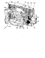
- FIG. 2 is an exploded perspective view showing the lens shift mechanism according to the present embodiment.
- the front side (z direction) in FIG. 2 is defined as the image projection direction of the projector 1, and the left and right directions in the image projection direction are defined.
- the projection lens device 40 (not shown) is attached to a projection lens mounting plate (not shown) provided in the liquid crystal driving unit 38 via fixing members 100A and 100B. That is, the fixed members 100A and 100B constituting the lens shift mechanism 42 are attached to the projection lens mounting plate of the liquid crystal driving unit 38, and the movable member 110 that is shiftable in the left-right direction is attached to the fixed members 100A and 100B. Yes. And the projection lens apparatus 40 (not shown) is attached to the movable member 110, and the movable member 110 and the projection lens apparatus 40 are united.
- a movable member (hereinafter referred to as “other movable member”) different from the movable member 110 can be shifted in the vertical direction with respect to the fixed members 100A and 100B. It is attached as follows. That is, in the shift of the projection lens device 40, the movable member 110 and other movable members are independently driven, the movable member 110 is operated in the left-right direction, and the other movable member is operated in the vertical direction.
- a motor M1 as a drive source for shifting the movable member 110 including the projection lens device 40 is attached to the fixed member 100B.
- the rotation of the motor M1 is transmitted to a rotation shaft (not shown) via the gear 132.
- the rotation of the rotation shaft is transmitted to a slide member (not shown) that slides in the left-right direction.
- the movable member 110 is connected and fixed to a part of the slide member, and shifts in the left-right direction (x direction) as the slide member slides.
- the rotation of the motor M2 is transmitted to a rotation shaft (not shown) via the gear 130.
- the rotation of the rotation shaft is transmitted to a slide member (not shown) that slides in the vertical direction.
- the other movable member is connected and fixed to a part of the slide member, and shifts in the vertical direction (y direction) as the slide member slides.
- the power transmission mechanism including the gears 130 and 132, the rotating shaft, the slide member, and the like shown in FIG. 2 is an example, and various other modes of power transmission mechanisms can be used.
- sensors SHL, SHC, and SHR for detecting the position state of the projection lens device 40 in the left-right direction are arranged on the fixed member 100A.
- sensors SVU, SVC, SVD for detecting the position state of the projection lens device 40 in the vertical direction are arranged on the fixed member 100B.
- FIG. 3 is an enlarged view showing a part of the lens shift mechanism (sensors SHL, SHC, SHR and light shielding plate 120) according to the present embodiment.
- FIG. 4 is a perspective view of the sensors SHL, SHC, and SHR of the lens shift mechanism according to the present embodiment.
- each of sensors SHL, SHC, and SHR is an optical sensor (for example, a PI sensor), and includes light emitting portions SHLE, SHCE, SHRE and light receiving portions SHLR, SHCR, SHRR. Yes.
- the light emitting units SHLE, SHCE, and SHRE include light emitting elements such as light emitting diodes, light emitting FETs, and EL elements.
- the light receiving portions SHLR, SHCR, and SHRR include light receiving elements that receive light from the light emitting portions SHLE, SHCE, and SHRE.
- various light receiving elements such as a photodiode, a phototransistor, an avalanche photodiode, and a pyroelectric infrared element can be used.
- the movable member 110 is provided with a light shielding plate 120 extending in the left-right direction. That is, the light shielding plate 120 is integrated with the movable member 110 and is shifted in the left-right direction with respect to the fixed members 100A and 100B.
- the light shielding plate 120 is provided with a gap 121 having a predetermined width W at the center in the left-right direction.
- the light shielding plate 120 is a shift path between the light emitting portions SHLE, SHCE, SHRE and the light receiving portions SHLR, SHCR, SHRR of the sensors SHL, SHC, SHR in a state where the fixing member 100A and the fixing member 100B are assembled.
- the sensors SHL, SHC, and SHR light emitted from the light emitting units SHLE, SHCE, and SHRE toward the light receiving units SHLR, SHCR, and SHRR is transmitted / blocked according to the shift operation of the light shielding plate 120.
- the sensors SHL, SHC, and SHR detect the position state of the projection lens device 40 based on transmission / blocking of light by the light shielding plate 120.
- the right end 122 of the light shielding plate 120 shields the sensor SHL, and based on the detection result, the projection lens device. It can be seen that 40 has reached the right limit of the shift range. Further, when the movable member 110 is shifted leftward, the left end 123 of the light shielding plate 120 shields the sensor SHR, so that the projection lens device 40 reaches the left limit of the shift range based on the detection result. I can know that. That is, the sensors SHR and SHL constitute a “left / right limit sensor” of the upper / lower / left / right limit sensors 62 (FIG. 1).
- the movable member 110 when the movable member 110 is shifted in the right direction or the left direction, the light from the light emitting unit SHCE passes through the gap 121 of the light shielding plate 120 and the light receiving unit SHCR receives the detection result. From this, it can be known that the projection lens device 40 has reached the center position of the shift range. That is, the sensor SHC constitutes the “left / right center sensor” of the upper / lower / left / right center sensor 64 (FIG. 1).
- three sensors SVU, SVC, and SVD are further arranged side by side at regular intervals in the vertical direction.
- Each of the sensors SVU, SVC, SVD includes an optical sensor (for example, a PI sensor) similar to the sensors SHL, SHC, SHR, and includes a light emitting unit and a light receiving unit.
- the other movable member is provided with a light shielding plate extending in the vertical direction, and the light shielding plate is integrated with the other movable members to be fixed to the fixed members 100A and 100B. On the other hand, it shifts up and down.
- the light shielding plate is provided with a gap portion having a predetermined width W at the center in the vertical direction.
- the light shielding plate is arranged so that a shift path is provided between the light emitting part and the light receiving part of the sensors SVU, SVC, SVD in a state where the fixing member 100A and the fixing member 100B are assembled. Thereby, in each of the sensors SVU, SVC, and SVD, light emitted from the light emitting unit toward the light receiving unit is temporarily blocked according to the shift operation of the light shielding plate.
- the sensors SVU, SVC, SVD detect the position state of the projection lens device 40 based on transmission / blocking of light by the light shielding plate.
- the upper end portion of the light shielding plate shields the sensor SVU, so that the projection lens device is based on the detection result. It can be seen that 40 has reached the upper limit of the shift range.
- the lower end portion of the light shielding plate shields the sensor SVD, so that the projection lens device 40 reaches the lower limit of the shift range based on the detection result. I can know that. That is, the sensors SVU and SVD constitute the “upper and lower limit sensor” of the upper and lower limit sensor 62 (FIG. 1).
- the other movable member when the other movable member is shifted upward or downward, the light from the light emitting part of the sensor SVC passes through the gap of the light shielding plate, and the light receiving part of the sensor SVC receives the light. Based on the detection result, it can be known that the projection lens device 40 has reached the center position of the shift range. That is, the sensor SVC constitutes the “vertical center sensor” of the vertical and horizontal center sensors 64 (FIG. 1).
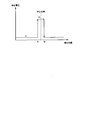
- FIG. 5 is a diagram illustrating an example of a detection voltage of the sensor SHC (right and left center sensor) according to the present embodiment.
- sensor SHC which is a left / right center sensor, outputs a detection voltage of L (logic low) level and receives light from the light emitting unit during a period in which light from the light emitting unit to the light receiving unit is blocked and is not received. During a period in which light to the part is received, a detection voltage of H (logic high) level is output.
- the gap portion of the light shielding plate 120 passes between the light emitting portion SHCE and the light receiving portion SHCR of the sensor SHC, whereby the light emitting portion SHCE. From the light-emitting unit SHCE is received by the light-receiving unit SHCR. At this time, the detection voltage of the sensor SHC rises from the L level to the H level at the timing when the light receiving unit SHCR receives the light from the light emitting unit SHCE (point A), and again at the timing when the light from the light emitting unit SHCE is interrupted. Fall from H level to L level (point B). As a result, as shown in FIG. 5, the detection voltage has a detection width having the center value of the center position of the shift range. This detection width is a value depending on the width W of the gap 121 provided in the light shielding plate 120.
- the projector 1 when the projector 1 is not in the center position (sensor SHC is at L level), the projector 1 projects the projection lens when the reset switch provided on the projector 1 main body or the remote control is turned on. It has a function of automatically returning the device 40 to the center position of the shift range.
- the processing for automatic return for example, as a means for returning to the center position of the shift range in the left-right direction, the projection lens device 40 is moved leftward or rightward from the position after the shift operation toward the center position.
- the detection voltage of the sensor SHC that is the left and right center sensor at that time can be monitored, and the movement of the projection lens device 40 can be stopped when the detection voltage rises from the L level to the H level.
- the detection width of the sensor SHC which is the left and right center sensor, depends on the width W of the gap 121 provided in the light shielding plate 120, if the gap is wide, the position shifted from the center position (point) In the vicinity of A or B), there is a problem that the movement of the projection lens device 40 is stopped. In addition, there is a problem that the stop position of the projection lens device 40 differs depending on the direction in which the projection lens device 40 is moved.
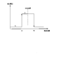
- the detection width of the left and right center sensor SHC increases as shown in FIG.
- the case where it returns to the center position of the shift range of the left-right direction with said structure is assumed. That is, when the projection lens device 40 is moved leftward or rightward from the position after the shift operation toward the center position, the projection lens is detected at the timing when the detection voltage of the left / right center sensor SHC rises from L level to H level. It is assumed that the movement of the device 40 is stopped.
- the stop position (point A or B) of the projection lens device 40 is greatly deviated from the center position of the shift range. Therefore, when the projection lens device 40 is moved rightward toward the center position, the stop position (point A) of the projection lens device 40 and when the projection lens device 40 is moved leftward toward the center position. A deviation corresponding to the detection width occurs between the projection lens device 40 and the stop position (point B). As a result, it becomes difficult to accurately return the projection lens device 40 to the center position.
- the center position can be strictly detected by arranging a sensor with a narrow detection width at the center position.
- a sensor with a narrow detection width at the center position.
- such a configuration has a problem that the manufacturing cost increases because it is necessary to create a high-strength mold in order to narrow the gap 121, and there is also a limit to narrow the detection width. This has a structural problem.
- the projection lens device 40 is moved back and forth in FIG. A processing procedure is shown.
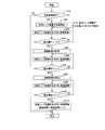
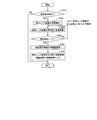
- FIG. 7 is a flowchart for explaining the automatic return process of the projection lens device 40 according to this embodiment. Note that the flowchart shown in FIG. 7 can be realized by executing a program stored in advance in the microcomputer 50.
- step S10 in order to execute the automatic return process of the projection lens device 40, after the shift operation of the projection lens device 40 (in a state where the projection lens device 40 is not at the center position), It is determined whether an automatic return is requested (step S10). Specifically, it is determined whether or not a reset switch provided on the projector 1 main body or the remote controller is turned on. If it is determined that the automatic return of the projection lens device 40 is not requested (NO in step S10), the process is terminated.
- step S10 if it is determined that the automatic return of the projection lens device 40 is requested by turning on the reset switch (YES in step S10), the position of the projection lens device 40 at the timing of starting the automatic return is determined. It is detected (step S20).
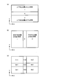
- FIG. 8 is a diagram for explaining position detection of the projection lens apparatus according to the present embodiment (description of step S20).
- the vertical position of the projection lens device 40 is in the vicinity of the center position of the shift range, the area above the vicinity of the center position, and the area below the vicinity of the center position. It is divided into and.
- the microcomputer 50 sequentially stores the operation amount and the operation direction of the switch, and “1”, “0”, “2” indicates in which of the three regions the projection lens device 40 is located. It is expressed using the numerical value of.
- the area above the center position of the vertical shift range is “1”
- the area near the center position is “0”
- the area below the center position is the area below the center position. “2”. This value is naturally updated according to the operation of the switch.
- the position of the projection lens device 40 in the left-right direction is in the vicinity of the center position of the shift range, in the region on the left side of the vicinity of the center position, and on the right side of the vicinity of the center position. It is divided into areas.
- the microcomputer 50 sequentially stores the operation amount and the operation direction of the switch, and “1”, “0”, “2” indicates in which of the three regions the projection lens device 40 is located. It is expressed using the numerical value of.
- the area on the left side of the center position of the shift range in the left-right direction is “1”
- the area near the center position is “0”
- the area on the right side of the center position is “ 2 ”. This value is naturally updated according to the operation of the switch.
- the position of the projection lens device 40 within the shift range becomes the position in the x direction (left-right direction) as shown in FIG. It can be expressed by coordinates consisting of a position in the y direction (up and down direction). For example, assuming that the center position of the shift range in the vertical and horizontal directions is coordinate (0, 0), the left area of the center position is coordinate (0, 1), and the right area of the center position is coordinate (0, 2). Can be expressed as Further, the region above and to the left of the center position can be represented by coordinates (1, 1).
- the microcomputer 50 updates the coordinates of the projection lens device 40 by sequentially storing the operation amount and operation direction of the switch during the execution of the shift operation with the center position (0, 0) in FIG. 8C as an initial value. To do. Then, the microcomputer 50 detects the position of the projection lens device 40 at the timing when the automatic return is started.
- step S20 the position of the projection lens device 40 detected in step S20 is on the right side of the center position (corresponding to coordinates (0, 2)).
- the automatic return of the projection lens device 40 is performed according to the procedure of steps S30 to S110.
- step S30 the microcomputer 50 causes the projection lens driving unit 60 to move the projection lens device 40 at a high speed in the direction toward the center position (that is, the left direction).
- the microcomputer 50 monitors the detection signal (detection voltage) from the left / right center sensor SHC, and determines whether or not the detection voltage has risen from the L level to the H level (assumed to be point A) (step A). S40). If the detection voltage of the left and right center sensor does not rise from the L level to the H level (NO in step S40), the process returns to step S30.
- detection signal detection voltage
- step S40 when it is determined that the detection voltage of the left / right center sensor SHC has risen from the L level to the H level (when YES is determined in step S40), the microcomputer 50 is built in at the same time as the detection voltage rises to the H level. By starting the counter, the measurement of the time (movement time) required for the projection lens device 40 to move the detection width (between A ⁇ B in FIG. 6) of the left and right center sensor SHC is started (step S50). After step 50, the microcomputer 50 causes the projection lens driving unit 60 to move the projection lens device 40 leftward at a low speed (step S60).
- step S70 it is determined whether or not the detection voltage of the left and right center sensor SHC has fallen from the H level to the L level (assumed to be point B) (step S70). If the detection voltage has not fallen from the H level to the L level (NO in step S70), the process returns to step S60.
- step S70 when it is determined that the detection voltage of the left / right center sensor SHC has fallen from the H level to the L level (YES in step S70), the microcomputer 50 requires a movement time required to move the detection width (FIG. 6). Is finished, and the travel time is calculated (step S80).
- the microcomputer 50 causes the projection lens driving unit 60 to drive the projection lens device 40 in the reverse direction and move it at high speed in the direction toward the center position (that is, the right direction) (step S90).
- step S100 it is determined whether or not the detection voltage of the left / right center sensor SHC falls from the H level to the L level. This determination in step S100 specifies the point A determined in step S40 again, and the starting point driven in step S110 described later is the point A. If the detection voltage has not fallen from the H level to the L level (NO in step S100), the process returns to step S90. On the other hand, if it is determined that the detection voltage of the left / right center sensor SHC has fallen from the H level to the L level (YES in step S100), the microcomputer 50 determines the movement time calculated by the projection lens device 40 in step S80.
- step S110 the projection lens device 40 moves so as to approach the center position of the detection width of the left / right center sensor SHC.
- the microcomputer 50 stores in advance the movement time when the projection lens device 40 in the detection width moves from the right direction and from the left direction.
- the reset switch is turned on for automatic return, the projection lens device 40 moves in the direction toward the center position of the projection lens device 40, and when the detection voltage of the left and right center sensor SHC rises from L level to H level, the projection lens device 40 Driving is performed so as to approach the center position using the movement time information stored in advance.
- FIG. 9 is a flowchart illustrating an automatic return process of the projection lens apparatus according to the modification of the present embodiment. The flowchart shown in FIG.
- step S210 in order to execute the automatic return process of the projection lens device 40, after the shift operation of the projection lens device 40 (in a state where the projection lens device 40 is not at the center position), It is determined whether or not automatic return is requested (step S210). Specifically, it is determined whether or not a reset switch provided on the projector 1 main body or the remote controller is turned on. If it is determined that the automatic return of the projection lens device 40 is not requested (NO in step S210), the process is terminated.
- step S210 if it is determined that the automatic return of the projection lens device 40 is requested by turning on the reset switch (YES in step S210), the position of the projection lens device 40 at the timing of starting the automatic return is determined. It is detected (step S220).
- step S220 the position of the projection lens device 40 detected in step S220 is on the right side of the center position (corresponding to coordinates (0, 2)). .
- the automatic return of the projection lens device 40 is performed according to the procedure of steps S230 to S260.
- step S230 the microcomputer 50 causes the projection lens driving unit 60 to move the projection lens device 40 at a high speed in the direction toward the center position (that is, the left direction).
- the microcomputer 50 monitors the detection signal (detection voltage) from the left and right center sensor SHC, and determines whether or not the detection voltage has risen from the L level to the H level (step S240). If the detection voltage of the left and right center sensor has not risen from the L level to the H level (NO in step S240), the process returns to step S230.
- detection signal detection voltage
- step S240 if it is determined that the detection voltage of the left / right center sensor SHC has risen from the L level to the H level (YES in step S240), the microcomputer 50 moves the detection width from the left direction stored in advance.
- the travel time information is called (step S250).
- step S260 the microcomputer 50 is driven at a low speed in the left direction by the drive time (corresponding to 1/2 of the travel time) using the travel time information (step S260). Thereby, the projection lens device 40 is driven so as to approach the center position from the right end portion of the detection width of the left-right center sensor SHC.
- the automatic return processing of the projection lens device 40 shown in FIGS. 7 and 9 is performed when the projection lens device 40 is moved leftward, and the projection lens device 40 detects the detection width of the left / right center sensor SHC.
- the projection lens device 40 is returned to the center position of the shift range in the left-right direction by driving the projection lens device 40 for a time (driving time) that halves the time required to move the lens (movement time). It is. According to this, since the detection width is not measured after the reset switch is turned on without newly adding a sensor capable of accurately detecting the center position, the operation time for automatically returning the center position of the projection lens apparatus by reset is shortened. Can do.
- the projection lens device 40 calculates the driving time using the moving time required for moving the detection width of the left-right center sensor SHC as an index.
- a configuration may be used in which the number of output of control pulses (for example, PWM (pulse width modulation) signals) output from the microcomputer 50 to the motors M1 and M2 (FIG. 2) included in the projection lens driving unit 60 is used as an index.
- control pulses for example, PWM (pulse width modulation) signals
- the microcomputer 50 measures the number of output times of the control pulse required for the projection lens device 40 to move the detection width of the left and right center sensor SHC, and sets the number of times corresponding to 1/2 of the measured number of times of output. Calculated as the number of driving times. Then, the projection lens device 40 is driven by the projection lens driving unit 60 in accordance with the calculated control pulse of the number of times of driving.
- the projection lens device 40 can be returned to the center position of the shift range by combining the left and right automatic return processing and the vertical automatic return processing.
- the automatic return processing of the projection lens device 40 when the initial automatic return position of the projection lens device 40 is the center position (when corresponding to the coordinates (0, 0)), is the projection lens device 40 at the center position? It is uncertain. In this case, for example, the projection lens is moved by once to an oblique position (in the case corresponding to the coordinates (1, 1)) that is located on the upper side and on the left side of the center position, and then an automatic return process is performed. The device 40 can be returned to the center position of the shift range. 7, when it is detected that the detection voltage of the left and right center sensor SHC rises from the L level to the H level or falls from the H level to the L level in steps S70 and S100 of the processing flow of FIG.
- step S110 is driven with the point at which the detection voltage of the left and right center sensor SHC falls from the H level to the L level.
- the detection width is measured in advance when the power source of the projector 1 is turned on.
- the user may arbitrarily give a command, which is executed in advance when the projector 1 is shipped. You can leave it.
- a liquid crystal projector is used as the projector, but the present invention is not limited to this.
- the technology of the present invention may be applied to other projectors such as a DLP (Digital Light Processing) (registered trademark) projector.
- DLP Digital Light Processing
- Projector projection-type image display device
- liquid crystal display drive unit light modulation unit
- projection lens device ... 40
- lens shift mechanism ... 42
- microcomputer control unit, timing means
- Measuring unit, storage unit ... 50
- projection lens drive unit drive mechanism
- vertical and horizontal center sensors center position detection unit
- motors ... M1, M2
Landscapes
- Physics & Mathematics (AREA)
- General Physics & Mathematics (AREA)
- Optics & Photonics (AREA)
- Projection Apparatus (AREA)
- Liquid Crystal (AREA)
- Lens Barrels (AREA)
Abstract
本発明は、投写レンズ装置を精度よく自動復帰させることができるレンズシフト機構および当該レンズシフト機構を搭載する投写型映像表示装置を提供することを目的とする。本発明のレンズシフト機構は、投写レンズ装置を一定範囲内の中心位置に復帰させる制御部と、前記投写レンズ装置の中心位置検出部とを備え、前記中心位置検出部は、1軸方向に沿って前記中心位置を中央値とする検出幅を有しており、前記制御部は、復帰を開始する時点における位置から前記中心位置に向かう方向を往方向として、前記投写レンズ装置を前記往方向に駆動させる第1の動作と、少なくとも前記検出幅分、前記投写レンズ装置を復方向に移動させる第2の動作と、前記往方向時に移動した前記検出幅の1/2分、前記検出幅を前記投写レンズ装置が往方向に移動する第3の動作を順に行うよう駆動機構に指令する。
Description
この発明は、レンズシフト機構および投写型映像表示装置に関し、より特定的には、投写レンズ装置の自動復帰機能を備えたレンズシフト機構および投写型映像表示装置に関する。
投写型映像表示装置としてのプロジェクタには、モータなどを利用して投写レンズの位置を一定範囲内でシフトさせて、その投写画面位置を調整するようにしているものがある。たとえば特開2004-62000号公報(特許文献1)には、投写レンズのシフト制御方法として、投写レンズ又は投写レンズと一体の可動部材を備え、シフト範囲の端部近傍に、投写レンズ又は可動部材の到来を検知するセンサを配置しておき、投写レンズのシフト中にセンサが投写レンズ又は可動部材の到来を検知した場合に、速度切換手段によりモータの駆動力を予め定めた値に低下させる構成を開示する。特許文献1では、かかる構成により、投写レンズのシフト動作時において、シフト範囲の端部で投写レンズや可動部材が他の固定部材に強く当たってロックされるような事態を防止している。
ここで、上述したレンズシフト機構を搭載するプロジェクタにおいては、シフト動作後に、投写レンズを、シフト範囲内の中心位置に自動復帰させる機能を備えるものがある。
このような自動復帰機能を実現するためには、たとえば、投写レンズのシフト範囲内の中心位置に、投写レンズが中心位置に到来したことを検知するためのセンサを配置しておき、投写レンズのシフト中に当該センサが投写レンズの到来を検知した場合に、モータの駆動を停止させることで、投写レンズを中心位置に復帰させることができる。
しかしながら、投写レンズの到来を検知するためのセンサとしては、一般的に、光の通過/遮断を利用した光学センサなどが利用されるため、該センサはその光学的構造で決まる固有の検出幅を有している。そのため、センサの検出幅の大きさによっては、センサの検知結果に基づく投写レンズの停止位置と、シフト範囲内の中心位置との間にずれが生じてしまう可能性がある。また、投写レンズを移動させる方向によって、投写レンズの停止位置が異なるという不具合も発生する。この結果、投写レンズを中心位置に正確に復帰させることが困難となってしまう。
このような不具合を回避するためには、中心位置に備えるセンサを中心位置が厳密に検出できるハードウェア構成とすることが考えられる。しかしながら、かかる構成では、さらに精密な部品を作成する必要があり、製造コストが高くなるという問題が発生する。また、センサの検出幅を狭くする事自体も限界があり、自動復帰精度がハードウェア構成の精度によって制限される。
それゆえ、この発明は、かかる課題を解決するためになされたものでありその目的は、投写レンズ装置を精度よく自動復帰させることができるレンズシフト機構および投写型映像表示装置を提供することである。
この発明のある局面に従うレンズシフト機構は、投写レンズ装置の光軸に直交する軸のうち、少なくとも1軸方向の一定範囲内で前記投写レンズ装置を往復移動させるためのレンズシフト機構であって、前記投写レンズ装置を少なくとも前記1軸方向に駆動するための駆動機構と、前記投写レンズ装置を、前記一定範囲内の中心位置に復帰させるように、前記駆動機構を制御する制御部と、前記投写レンズ装置が前記中心位置に至ったことを検出するための中心位置検出部とを備え、前記中心位置検出部は、前記1軸方向に沿って前記中心位置を中央値とする検出幅を有しており、前記制御部は、復帰を開始する時点における位置から前記中心位置に向かう方向を往方向として、前記駆動機構により、前記投写レンズ装置を前記往方向に移動させ、前記検出幅の一端を通り過ぎて少なくとも前記検出幅を通る第1の動作と、前記第1の動作の後に、前記駆動機構により、少なくとも前記検出幅分、前記投写レンズ装置を復方向に移動させるための第2の動作と、前記第2の動作によって前記投写レンズ装置が少なくとも前記検出幅を移動した後に、前記駆動機構により、前記往方向時に移動した前記検出幅の1/2分、前記検出幅の一端から前記投写レンズ装置を往方向に移動させるための第3の動作と、を指令すること特徴とする。好ましくは、前記制御部は、前記中心位置検出部の検出値に基づき、前記第1の動作によって前記投写レンズ装置が前記検出幅を移動するのに要した移動時間を計時するための計時手段をさらに含み、前記第3の動作は、前記計時手段により計時された前記移動時間に応じて、前記駆動機構により、前記検出幅の1/2に相当する時間、前記投写レンズ装置を往方向に移動する。
好ましくは、前記駆動機構は、前記制御部から出力される制御パルスに従って駆動するモータとを含み、前記制御部は、前記中心位置検出部の検出値に基づき、前記第1の動作によって前記投写レンズ装置が前記検出幅を移動するのに要した制御パルスの出力回数を計測するための計測手段をさらに含み、前記第3の動作は、前記計測手段により計測された前記制御パルス数の出力回数の1/2に相当する回数を駆動回数として、前記駆動機構により、前記投写レンズ装置を往方向に移動する。
この発明の別の局面に従うレンズシフト機構は、投写レンズ装置の光軸に直交する軸のうち、少なくとも1軸方向の一定範囲内で前記投写レンズ装置を往復移動させるためのレンズシフト機構であって、前記投写レンズ装置を少なくとも前記1軸方向に駆動するための駆動機構と、前記投写レンズ装置を、前記一定範囲内の中心位置に復帰させるように、前記駆動機構を制御する制御部と前記投写レンズ装置が前記中心位置に至ったことを検出するための中心位置検出部と、を備え、前記中心位置検出部は、前記1軸方向に沿って前記中心位置を中央値とする検出幅を有しており、前記制御部は、復帰を開始する時点における位置から前記中心位置に向かう方向を往方向として、前記駆動機構により前記投写レンズ装置を前記往方向に移動させ、前記検出幅の一端まで移動させるための第1の動作と、前記投写レンズ装置が前記検出幅を移動するとき、予め往方向の移動における前記検出幅の情報を記憶した記憶部からの前記検出幅情報に基づいて前記検出幅の1/2分、前記検出幅の一端から前記投写レンズ装置が往方向に移動させるための第2の動作と、を指令することを特徴とする。
この発明の別の局面に従う投写型映像表示装置は、上記いずれかのレンズシフト機構と、光源からの光を映像入力信号に基づいて映像変調させる光変調部と、前記レンズシフト機構により支持され、光変調部からの光を投写面上に拡大投写させる投写部と、を備えることを特徴とする。
この発明によれば、投写レンズ装置を精度よく自動復帰させることができる。
以下、本発明の実施形態について、図面を参照しながら詳細に説明する。尚、図中の同一又は相当する部分には同一符号を付してその説明は繰返さない。
図1は、本実施形態に係る投写型映像表示装置を説明する図である。
図1を参照して、本実施形態に係る投写型映像表示装置(以下、「プロジェクタ」と記す。)1を説明する。プロジェクタ1は、液晶デバイスを利用して映像を投影する液晶プロジェクタであって、スクリーンに液晶デバイスにより表示される映像の光を投写することにより、映像を投影(表示)する。投写面は、スクリーンに限定されず、壁面であってもよい。
プロジェクタ1は、ユーザが操作するリモコン(リモートコントローラの略)から送信される赤外線変調されたリモコン信号を受信するリモコン受信部10と、入力部20とを備える。リモコン信号には、プロジェクタ1を遠隔制御するためのコマンド信号が含まれる。入力部20は、外部の信号供給装置(図示せず)から供給される映像信号を受け付けるための入力ポートを含む。信号供給装置には、DVD(Digital Versatile Disc)再生装置、Blu-Rayディスク再生装置などのデジタル信号を出力するデジタル信号供給装置と、コンピュータなどのアナログ信号を出力するアナログ信号供給装置とが含まれる。
プロジェクタ1は、レシーバ部30と、映像信号処理回路32と、OSD(On Screen Display)回路34と,DAC(Digital Analog Converter)36と、マイコン(マイクロコンピュータ)50と、液晶表示駆動部38と、投写レンズ装置40と、レンズシフト機構42とをさらに備える。
マイコン50は、リモコン(図示せず)からリモコン受信部10を介して入力したコマンド信号に基づいて、制御指令を生成してプロジェクタ1の各部へ出力する。この制御指令は、マイコン50の内部に配された不揮発性メモリ(図示せず)に記憶されたプログラムやデータから演算処理して実行される。
レシーバ部30は、入力部20から与えられる映像信号を受信して出力する。レシーバ部30は、受信したアナログ映像信号をデジタル信号に変換するADC(Analog Digital Converter)機能と、HDCP(High-Bandwidth Digital Content Protection System)に従う認証機能および暗号の復号機能とを有する。尚、HDCPとは、HDMI(High Definition Multimedia Interface)に従って伝送されるデータの暗号化を実現するために用いられる。これにより、デジタル伝送路上を伝送される映像信号などのコンテンツが不正にコピーされるのを防止できる。ここでは、デジタル伝送路は、HDMIに従ってデータ・信号を伝送する経路であるとしているが、DVI(Digital Visual Interface)に従った伝送経路であってもよい。
映像信号処理回路32は、レシーバ部30から出力された映像信号を表示のための信号に処理して出力する。具体的には、映像信号処理回路32は、レシーバ部30からの映像信号を1フレーム(1画面)ごとにフレームメモリ(図示せず)に書き込むとともに、フレームメモリに記憶された映像を読み出す。そして、この書き込みと読み出しの処理の過程において、各種の映像処理を施すことにより、入力された映像信号を変換して投写映像用の映像信号である映像データを生成する。
OSD回路34は、映像信号処理回路32から出力される映像信号に、マイコン50から与えられる情報に基づく画像データの信号を重畳して、重畳された後に映像信号を出力する。
DAC36は、OSD回路34から出力された映像信号を入力し、アナログ信号に変換して液晶表示駆動部38へ出力する。
液晶表示駆動部38、投写レンズ装置40およびランプ(図示せず)は、DAC36から出力される映像信号に従って、マイコン50の制御の下に、スクリーンに映像を表示するための「表示部」に相当する。
表示部の動作について説明する。照明装置であるランプ(図示せず)は、たとえば超高圧水銀ランプ、メタルハライドランプ、キセノンランプなどからなる。ランプは、コネクタを介してプロジェクタ1に着脱自在に取り付けられる。ランプからは、略平行光となって光が液晶表示駆動部38に出射される。
液晶表示駆動部38は、図示しないレンズおよびプリズムを含む光学系と、R,G,Bの各液晶パネルとを含む。液晶表示駆動部38では、内部の図示しないレンズ系を通過したランプからの光は、R,G,Bの各液晶パネルに光量分布が均一となるように入射する。レンズ系を介して入射された光のうち、青色波長帯の光(以下、「B光」という)、赤色波長帯の光(以下、「R光」という)、緑色波長帯の光(以下、「G光」という)は、略平行光でR,G,Bの各液晶パネルに入射する。各液晶パネルは、DAC36から与えられるR,G,Bに対応した映像信号に応じて駆動され、その駆動状態に応じて光を変調する。液晶パネルによって変調されたR光,G光,B光は、ダイクロイックプリズムによって色合成された後に、投写レンズ装置40によって、スクリーン上に拡大投写される。
投写レンズ装置40は、投写光をスクリーンに結像させるためのレンズ群と、これらレンズ群の一部を光軸方向に変化させて投写映像のズーム状態およびフォーカス状態を調整するためのアクチュエータを備えている。
投写レンズ装置40は、スクリーンへの投写画面位置を上下方向および左右方向に調整できるように、液晶パネルおよびダイクロイックプリズムの光軸と垂直な平面内で一定範囲、シフト(移動)可能に構成されている。尚、投写レンズ装置40のシフト動作は、レンズシフト機構42で行なわせることができる。
レンズシフト機構42は、投写レンズ装置40の位置を一定範囲内でシフトさせて、その投写画面位置を調整する。レンズシフト機構42は、投写レンズ駆動部60と、上下左右限界センサ62と、上下左右中心センサ64とを含む。
投写レンズ駆動部60は、モータなどの動力駆動源と、歯車機構などの動力伝達機構とを組み合わせて構成される。モータの回転力が、動力伝達機構によって上下方向又は左右方向の直線移動力に変換されることにより、投写レンズ装置40を上下方向又は左右方向にシフトさせることができる。モータの回転数は、マイコン50により制御される。
上下左右限界センサ62および上下左右中心センサ64は、投写レンズ装置40のシフト範囲の所定位置に配置されて、投写レンズ装置40の位置状態を検出する。
具体的には、上下左右限界センサ62は、投写レンズ装置40が、上下方向のシフト範囲の上限又は下限に至ったことを検出するための上下限界センサと、投写レンズ装置40が、左右方向のシフト範囲の左限又は右限に至ったことを検出するための左右限界センサとを含む。
また、上下左右中心センサ64は、投写レンズ装置40が、上下方向のシフト範囲の中心位置に至ったことを検出するための上下中心センサと、投写レンズ装置40が、左右方向のシフト範囲の中心位置に至ったことを検出するための左右中心センサとを含む。
上下左右限界センサ62および上下左右中心センサ64には、各種のものが利用できるが、たとえば光の透過/遮断を利用したPI(フォトインタプラタ)センサなどの光学センサが利用できる。上下左右限界センサ62および上下左右中心センサ64の検出信号は、マイコン50に出力される。
投写レンズ装置40のシフト動作は、プロジェクタ1本体又はリモコンに設けられたスイッチで操作することができる。たとえば、リモコンに設けられたスイッチをONすることでモータが駆動されて投写レンズ装置40がシフト範囲を移動するものとし、該スイッチをOFFすることでモータが停止されて投写レンズ装置40の移動が止まる。
マイコン50は、上下左右限界センサ62および上下左右中心センサ64の検出信号に基づき、シフト範囲内で投写レンズ装置40を上下方向又は左右方向に往復移動させるようにモータを駆動制御する。
また、マイコン50は、上述した投写レンズ装置40のシフト動作において、投写レンズ装置40の位置状態を監視しており、シフト動作後において、プロジェクタ1本体又はリモコンに設けられたリセットスイッチがONされたときには、後述する方法によって、投写レンズ装置40をシフト範囲の中心位置に自動復帰させる。
図2は、本実施形態に係るレンズシフト機構を示す分解斜視図である。尚、以下の説明においては、図2の紙面手前方向(z方向)をプロジェクタ1の映像投写方向とし、該映像投写方向に向かって左右を規定する。
図2を参照して、投写レンズ装置40(図示せず)は、液晶駆動部38に設けられた投写レンズ取付板(図示せず)に、固定部材100A,100Bを介して取り付けられている。すなわち、液晶駆動部38の投写レンズ取付板に、レンズシフト機構42を構成する固定部材100A,100Bが取り付けられ該固定部材100A,100Bに対して左右方向にシフト可能な可動部材110が取り付けられている。そして、可動部材110に投写レンズ装置40(図示せず)が取り付けられて、可動部材110と投写レンズ装置40とが一体になっている。尚、本実施形態では説明の便宜上、図示は省略するが可動部材110とは異なる可動部材(以下「他の可動部材」と記す。)が固定部材100A、100Bに対して上下方向へシフト可能なように取り付けられている。すなわち、投写レンズ装置40のシフトにおいて、可動部材110と他の可動部材がそれぞれ独立に駆動し、左右方向の駆動は可動部材110が動作し、上下方向の駆動は他の可動部材により動作する。
固定部材100Bには、投写レンズ装置40を含んだ可動部材110をシフトさせる駆動源としてのモータM1が取り付けられている。モータM1の回転は、歯車132を介して回転軸(図示せず)に伝達される。回転軸の回転は、左右方向にスライドするスライド部材(図示せず)に伝達される。可動部材110は、スライド部材の一部と連結固定されており、このスライド部材のスライドに従って、左右方向(x方向)にシフトする。また、モータM2の回転は、歯車130を介して回転軸(図示せず)に伝達される。回転軸の回転は、上下方向にスライドするスライド部材(図示せず)に伝達される。他の可動部材は、スライド部材の一部と連結固定されており、このスライド部材のスライドに従って、上下方向(y方向)にシフトする。
尚、図2で示した歯車130、132、回転軸およびスライド部材などから成る動力伝達機構は、一例であり、その他の様々な態様の動力伝達機構を用いることができる。
さらに、固定部材100Aには、左右方向における投写レンズ装置40の位置状態を検出するためのセンサSHL,SHC,SHRが配置されている。また、固定部材100Bには、上下方向における投写レンズ装置40の位置状態を検出するためのセンサSVU,SVC,SVDが配置されている。
図3は、本実施形態に係るレンズシフト機構の一部(センサSHL,SHC,SHRおよび遮光板120)を拡大して示す図である。
図3を参照して、3個のセンサSHL,SHC,SHRは、左右方向に一定の間隔で並べて配置されている。図4は、本実施形態に係るレンズシフト機構のセンサSHL,SHC,SHRの斜視図を示す。
図3および図4を参照して、センサSHL,SHC,SHRの各々は、光学センサ(たとえばPIセンサ)であり、発光部SHLE、SHCE、SHREと受光部SHLR、SHCR、SHRRとを有している。発光部SHLE、SHCE、SHREには、発光ダイオード、発光FET、EL素子などの発光素子が含まれる。また、受光部SHLR、SHCR、SHRRには、発光部SHLE、SHCE、SHREからの光を受光する受光素子が含まれる。受光素子には、フォトダイオード、フォトトランジスタ、アバランシュフォトダイオード、焦電型赤外素子などの各種受光素子を用いることができる。
図3に示すように、可動部材110には、左右方向に延在する遮光板120が配置されている。すなわち、遮光板120は、可動部材110と一体となって、固定部材100Aおよび100Bに対して左右方向にシフトする。遮光板120には、左右方向の中央部に所定の幅Wの間隙部121が設けられている。
さらに、遮光板120は、固定部材100Aと固定部材100Bとが組み付けられた状態で、センサSHL,SHC,SHRの発光部SHLE、SHCE、SHREと受光部SHLR、SHCR、SHRRとの間をシフト通路とするように配置される。これにより、センサSHL,SHC,SHRの各々において、発光部SHLE、SHCE、SHREから受光部SHLR、SHCR、SHRRに向けて照射された光が、遮光板120のシフト動作に応じて透過/遮断される。センサSHL,SHC,SHRは、遮光板120による光の透過/遮断に基づいて、投写レンズ装置40の位置状態を検出する。
具体的には、投写レンズ装置40を含む可動部材110を右方向にシフトさせたときに、遮光板120の右端部122がセンサSHLを遮光することにより、その検出結果に基づいて、投写レンズ装置40がシフト範囲の右限に至ったことを知ることができる。また、可動部材110を左方向にシフトさせたときに、遮光板120の左端部123がセンサSHRを遮光することにより、その検出結果に基づいて、投写レンズ装置40がシフト範囲の左限に至ったことを知ることができる。すなわち、センサSHRおよびSHLは、上下左右限界センサ62(図1)のうちの「左右限界センサ」を構成する。
これに対して、可動部材110を右方向又は左方向にシフトさせたときに、遮光板120の間隙部121を発光部SHCEからの光が通過し受光部SHCRが受光することにより、その検出結果に基づいて、投写レンズ装置40がシフト範囲の中心位置に至ったことを知ることができる。すなわち、センサSHCは、上下左右中心センサ64(図1)のうちの「左右中心センサ」を構成する。
尚、図2ではさらに、3個のセンサSVU,SVC,SVDが、上下方向に一定の間隔で並べて配置されている。センサSVU,SVC,SVDの各々は、センサSHL,SHC,SHRと同様の光学センサ(たとえばPIセンサ)からなり、発光部と受光部とを有している。また、図示は省略するが、他の可動部材には、上下方向に延在する遮光板が配置されており、該遮光板は、他の可動部材と一体となって、固定部材100Aおよび100Bに対して上下方向にシフトする。該遮光板には、上下方向の中央部に所定の幅Wの間隙部が設けられている。
そして、該遮光板は、固定部材100Aと固定部材100Bとが組み付けられた状態で、センサSVU,SVC,SVDの発光部と受光部との間をシフト通路とするように配置される。これにより、センサSVU,SVC,SVDの各々において、発光部から受光部に向けて照射された光が、該遮光板のシフト動作に応じて一時的に遮断される。センサSVU,SVC,SVDは、該遮光板による光の透過/遮断に基づいて、投写レンズ装置40の位置状態を検出する。
具体的には、投写レンズ装置40を含む他の可動部材を上方向にシフトさせたときに、該遮光板の上端部がセンサSVUを遮光することにより、その検出結果に基づいて、投写レンズ装置40がシフト範囲の上限に至ったことを知ることができる。また、他の可動部材を下方向にシフトさせたときに、該遮光板の下端部がセンサSVDを遮光することにより、その検出結果に基づいて、投写レンズ装置40がシフト範囲の下限に至ったことを知ることができる。すなわち、センサSVUおよびSVDは、上下左右限界センサ62(図1)のうちの「上下限界センサ」を構成する。
これに対して、他の可動部材を上方向又は下方向にシフトさせたときに、該遮光板の間隙部をセンサSVCの発光部からの光が通過しセンサSVCの受光部が受光することにより、その検出結果に基づいて、投写レンズ装置40がシフト範囲の中心位置に至ったことを知ることができる。すなわち、センサSVCは、上下左右中心センサ64(図1)のうちの「上下中心センサ」を構成する。
図5は、本実施形態に係るセンサSHC(左右中心センサ)の検出電圧の一例を示す図である。
図5を参照して、左右中心センサであるセンサSHCは、発光部から受光部への光が遮断されて受光されない期間において、L(論理ロー)レベルの検出電圧を出力し、発光部から受光部への光が受光される期間において、H(論理ハイ)レベルの検出電圧を出力する。
本実施形態では、可動部材110を右方向又は左方向にシフトさせたときに、遮光板120の間隙部がセンサSHCの発光部SHCEと受光部SHCRとの間を通過することによって、発光部SHCEからの光が遮光板120を一時的に通過し、発光部SHCEからの光を受光部SHCRが受光する。このとき、センサSHCの検出電圧は、受光部SHCRが発光部SHCEからの光を受光したタイミングでLレベルからHレベルに立ち上がり(ポイントA)、再び発光部SHCEからの光が遮断されたタイミングでHレベルからLレベルに立ち下がる(ポイントB)。この結果、図5に示すように、検出電圧は、シフト範囲の中心位置を中央値とする検出幅を有することとなる。尚、この検出幅は、遮光板120に設けられた間隙部121の幅Wに依存した値となる。
ここで、上述したように、プロジェクタ1は、投写レンズ装置40が中心位置にない状態(センサSHCがLレベル)において、プロジェクタ1本体又はリモコンに設けられたリセットスイッチがONされたときには、投写レンズ装置40をシフト範囲の中心位置に自動復帰させる機能を有している。この自動復帰のための処理については、たとえば、左右方向のシフト範囲の中心位置に復帰させる手段として、投写レンズ装置40をシフト動作後の位置から中心位置に向かって左方向又は右方向に移動させるとともに、そのときの左右中心センサであるセンサSHCの検出電圧を監視し、該検出電圧がLレベルからHレベルに立ち上がったタイミングで投写レンズ装置40の移動を停止させる構成を採ることができる。
しかしながら、左右中心センサであるセンサSHCの検出幅は、遮光板120に設けられた間隙部121の幅Wに依存しているため、該間隙部の幅が広ければ中心位置からずれた位置(ポイントA又はB近傍)で投写レンズ装置40の移動が停止されてしまう不具合が発生する。また、投写レンズ装置40を移動させる方向によって、投写レンズ装置40の停止位置が異なるという不具合も発生する。
具体的には、遮光板120の間隙部の幅が広くなるに従って、図6に示すように、左右中心センサSHCの検出幅が増大する。ここで、上記の構成によって左右方向のシフト範囲の中心位置に復帰させる場合を想定する。すなわち、投写レンズ装置40をシフト動作後の位置から中心位置に向かって左方向又は右方向に移動させたときに、左右中心センサSHCの検出電圧がLレベルからHレベルに立ち上がったタイミングで投写レンズ装置40の移動を停止させるものとする。
この場合、左右中心センサSHCの検出幅が広いために、投写レンズ装置40の停止位置(ポイントA又はB)はシフト範囲の中心位置から大きくずれたものとなる。そのため、投写レンズ装置40を中心位置に向かって右方向に移動させたときの投写レンズ装置40の停止位置(ポイントA)と、投写レンズ装置40を中心位置に向かって左方向に移動させたときの投写レンズ装置40の停止位置(ポイントB)との間には該検出幅に相当するずれが生じる。この結果、投写レンズ装置40を中心位置に正確に復帰させることが困難となってしまう。
このような不具合を回避するためには、検出幅が狭く設計されたセンサを中心位置に配置することにより、中心位置を厳密に検出できる。しかしながら、かかる構成は、間隙部121を狭くするために、高強度の金型を作成する必要があるため、製造コストが高くなるという問題を有し、さらに検出幅を狭くする限界も存在することで構成的な問題点を有することとなる。
そこで、本実施形態に係るプロジェクタ1においては、高価な部品を用いずとも、投写レンズ装置40をシフト範囲の中心位置に精度よく自動復帰させる手段として、図7に投写レンズ装置40の往復移動の処理手順を示す。
図7は、本実施形態による投写レンズ装置40の自動復帰処理を説明するフローチャートである。尚、図7に示すフローチャートは、マイコン50において予め格納したプログラムを実行することで実現できる。
図7を参照して、まず、投写レンズ装置40の自動復帰処理を実行するために、投写レンズ装置40のシフト動作後(投写レンズ装置40が中心位置にない状態)において、投写レンズ装置40の自動復帰が要求されているか否かが判断される(ステップS10)。具体的には、プロジェクタ1本体又はリモコンに設けられたリセットスイッチがONされたか否かが判断される。投写レンズ装置40の自動復帰が要求されていないと判断された場合(ステップS10のNO判定時)には、処理を終了する。
一方、リセットスイッチがONされることによって、投写レンズ装置40の自動復帰が要求されたと判断されると(ステップS10のYES判定時)、自動復帰を開始するタイミングでの投写レンズ装置40の位置が検出される(ステップS20)。
具体的には、マイコン50は、シフト動作の実行中における、プロジェクタ1本体又はリモコンに設けられたスイッチの操作の履歴に基づき、投写レンズ装置40の位置を検出する。図8は、本実施形態に係る投写レンズ装置の位置検出を説明する図である(ステップS20の説明)。図8(a)を参照して、投写レンズ装置40の上下方向の位置は、シフト範囲の中心位置付近と、該中心位置付近よりも上側の領域と、該中心位置付近よりも下側の領域とに区分される。マイコン50は、スイッチの操作量および操作方向を逐次記憶しており、投写レンズ装置40がこれら3つの領域のうちのどの領域に位置しているかを、「1」、「0」、「2」の数値を用いて表記する。図8(a)の例では、上下方向のシフト範囲の中心位置よりも上側の領域を「1」とし、該中心位置付近の領域を「0」とし、該中心位置よりも下側の領域を「2」とする。この数値は、当然スイッチの操作に応じて更新される。
同様に、図8(b)を参照して、投写レンズ装置40の左右方向の位置は、シフト範囲の中心位置付近と、該中心位置付近よりも左側の領域と、該中心位置付近よりも右側の領域とに区分される。マイコン50は、スイッチの操作量および操作方向を逐次記憶しており、投写レンズ装置40がこれら3つの領域のうちのどの領域に位置しているかを、「1」、「0」、「2」の数値を用いて表記する。図8(b)の例では、左右方向のシフト範囲の中心位置よりも左側の領域を「1」とし、該中心位置付近の領域を「0」とし、該中心位置よりも右側の領域を「2」とする。この数値は、当然スイッチの操作に応じて更新される。
そして、図8(a)および(b)を組合せることによって、シフト範囲内での投写レンズ装置40の位置は、図8(c)に示すような、x方向(左右方向)の位置と、y方向(上下方向)の位置とからなる座標で表すことができる。たとえば、上下および左右方向におけるシフト範囲の中心位置を座標(0,0)として、当該中心位置の左側の領域を座標(0,1)、当該中心位置の右側の領域を座標(0,2)で表すことができる。また、当該中心位置よりも上側かつ左側の領域については、座標(1,1)で表すことができる。
マイコン50は、図8(c)の中心位置(0,0)を初期値として、シフト動作の実行中におけるスイッチの操作量および操作方向を逐次記憶することにより、投写レンズ装置40の座標を更新する。そして、マイコン50は、自動復帰を開始すると当該タイミングにおける投写レンズ装置40の位置を検出する。
再び図7を参照して、ステップS20において検出される投写レンズ装置40の位置が、中心位置よりも右側である場合(座標(0,2)に相当する場合)を想定する。この場合、投写レンズ装置40の自動復帰は、ステップS30~S110による手順に従って行なわれる。
具体的には、ステップS30では、マイコン50は、投写レンズ駆動部60により、投写レンズ装置40を、中心位置に向かう方向(すなわち、左方向)に高速で移動させる。このとき、マイコン50は、左右中心センサSHCからの検出信号(検出電圧)をモニタしており、検出電圧がLレベルからHレベルに立ち上がったか否かを判断する(仮にポイントAとする)(ステップS40)。左右中心センサの検出電圧がLレベルからHレベルに立ち上がっていなければ(ステップS40のNO判定時)、処理はステップS30に戻される。
一方、左右中心センサSHCの検出電圧がLレベルからHレベルに立ち上がったと判断されると(ステップS40のYES判定時)、ステップ50と同時にマイコン50は、検出電圧がHレベルに立ち上がったタイミングで内蔵するカウンタを起動することにより、投写レンズ装置40が左右中心センサSHCの検出幅(図6のA→B間)を移動するのに要する時間(移動時間)の計測を開始する(ステップS50)。ステップ50の後、マイコン50は、投写レンズ駆動部60により、投写レンズ装置40を左方向へ低速で移動させる(ステップS60)。
次に、左右中心センサSHCの検出電圧がHレベルからLレベルに立ち下がったか否かが判断される(仮にポイントBとする)(ステップS70)。検出電圧がHレベルからLレベルに立ち下がっていなければ(ステップS70のNO判定時)、処理はステップS60に戻される。
一方、左右中心センサSHCの検出電圧がHレベルからLレベルに立ち下がったと判断されると(ステップS70のYES判定時)、マイコン50は、検出幅(図6)を移動するのに要する移動時間の計測を終了し、移動時間を算出する(ステップS80)。
次に、マイコン50は、投写レンズ駆動部60により、投写レンズ装置40を、逆方向へ駆動させ、中心位置に向かう方向(すなわち、右方向)に高速で移動させる(ステップS90)。
次に、左右中心センサSHCの検出電圧がHレベルからLレベルに立ち下がったか否かが判断される(ステップS100)。このステップS100での判断は、ステップS40で判断されたポイントAを再度特定するものであり、後述するステップS110にて駆動される始点がポイントAとなる。検出電圧がHレベルからLレベルに立ち下がっていなければ(ステップS100のNO判定時)、処理はステップS90に戻される。一方、左右中心センサSHCの検出電圧がHレベルからLレベルに立ち下がったと判断されると(ステップS100のYES判定時)、マイコン50は、投写レンズ装置40を、ステップS80で算出した移動時間を用いて駆動時間(駆動時間=移動時間の1/2に相当)だけ左方向に低速で再駆動させる(ステップS110)。これにより、投写レンズ装置40は、左右中心センサSHCの検出幅の中心位置に近づくように移動する。このような構成にすることにより、左方向から検出幅の移動時間を測定した時と右方向から検出幅の移動時間を測定した時で、歯車の噛み合い方や駆動抵抗力の違いにより双方の移動時間が異なってしまう場合であっても、一度移動時間を測定した方向と同じ方向から駆動時間(移動時間の1/2に相当)だけ駆動させることができる。従って、投写レンズ装置40を精度よく中心位置へ自動復帰させることができる。
(変形例)
以下において、上述した実施形態の変形例に係る投写型映像表示装置の構成ついて、図面を参照しながら説明する。尚、変形例において、第1実施形態と重複するところは、説明を省略する。変形例は、上述した実施形態と比較すると以下の点で異なる。すなわち、マイコン50は、予め検出幅における投写レンズ装置40が右方向から移動した場合及び左方向から移動した場合の移動時間を記憶しておく。自動復帰のためにリセットスイッチがONさせると、投写レンズ装置40の中心位置へ向かう方向へ移動し、左右中心センサSHCの検出電圧がLレベルからHレベルに立ち上がった際、投写レンズ装置40は、予め記憶されている移動時間情報を使用して中心位置に近づくよう駆動する。以下において、上述した実施形態の変形例に係る投写レンズ装置の自動復帰処理を詳細に説明する。図1を再び参照して、マイコン50は、プロジェクタ1の電源がONされると各種初期化動作と共に投写レンズ装置40を左右上下方向に動作させる。この際、左方向又は右方向から検出幅を通り過ぎるのに要する時間をそれぞれ計測し、マイコン50に記憶させる。同様に、上方向又は下方向から検出幅を通り過ぎるのに要する時間をそれぞれ計測し、それぞれの計測結果は、マイコン50の不揮発性メモリに記憶する。図9は、本実施形態の変形例に係る投写レンズ装置の自動復帰処理を説明するフローチャートである。尚、図9に示すフローチャートは、マイコン50において予め格納したプログラムを実行することで実現できる。図9を参照して、まず、投写レンズ装置40の自動復帰処理を実行するために、投写レンズ装置40のシフト動作後(投写レンズ装置40が中心位置にない状態)において、投写レンズ装置40の自動復帰が要求されているか否かが判断される(ステップS210)。具体的には、プロジェクタ1本体又はリモコンに設けられたリセットスイッチがONされたか否かが判断される。投写レンズ装置40の自動復帰が要求されていないと判断された場合(ステップS210のNO判定時)には、処理を終了する。
一方、リセットスイッチがONされることによって、投写レンズ装置40の自動復帰が要求されたと判断されると(ステップS210のYES判定時)、自動復帰を開始するタイミングでの投写レンズ装置40の位置が検出される(ステップS220)。
ここで図7で想定した状態と同じように、ステップS220において検出される投写レンズ装置40の位置が、中心位置よりも右側である場合(座標(0,2)に相当する場合)を想定する。この場合、投写レンズ装置40の自動復帰は、ステップS230~S260による手順に従って行なわれる。
具体的には、ステップS230では、マイコン50は、投写レンズ駆動部60により、投写レンズ装置40を、中心位置に向かう方向(すなわち、左方向)に高速で移動させる。このとき、マイコン50は、左右中心センサSHCからの検出信号(検出電圧)をモニタしており、検出電圧がLレベルからHレベルに立ち上がったか否かを判断する(ステップS240)。左右中心センサの検出電圧がLレベルからHレベルに立ち上がっていなければ(ステップS240のNO判定時)、処理はステップS230に戻される。
一方、左右中心センサSHCの検出電圧がLレベルからHレベルに立ち上がったと判断されると(ステップS240のYES判定時)、マイコン50は、予め格納されている左方向から検出幅を移動した場合の移動時間情報を呼び出す(ステップS250)。次にマイコン50は、移動時間情報を用いて駆動時間(駆動時間=移動時間の1/2に相当)だけ左方向に低速で駆動させる(ステップS260)。これにより、投写レンズ装置40は、左右中心センサSHCの検出幅の右端部から中心位置に近づくように駆動する。
以上に述べたように、図7及び図9に示す投写レンズ装置40の自動復帰処理は、投写レンズ装置40を左方向に移動させたときに、投写レンズ装置40が左右中心センサSHCの検出幅を移動するのに要する時間(移動時間)を1/2した時間分(駆動時間)、投写レンズ装置40を駆動させることにより、投写レンズ装置40を左右方向のシフト範囲の中心位置に復帰させるものである。これによれば、中心位置を厳密に検出できるセンサを新たに追加することなく、リセットスイッチがONの後に検出幅を測定しないためリセットによる投写レンズ装置の中心位置自動復帰の動作時間が短縮することができる。
尚、図7及び図9の処理フローでは、投写レンズ装置40が、左右中心センサSHCの検出幅を移動するのに要する移動時間を指標にして駆動時間を算出する構成としたが、移動時間に代えて、マイコン50が投写レンズ駆動部60に含まれるモータM1,M2(図2)に出力する制御パルス(たとえば、PWM(パルス幅変調)信号)の出力回数を指標とする構成としてもよい。
この場合は、マイコン50は、投写レンズ装置40が、左右中心センサSHCの検出幅を移動するのに要する制御パルスの出力回数を計測し、その計測した出力回数の1/2に相当する回数を駆動回数として算出する。そして、算出した駆動回数の制御パルスに従って、投写レンズ駆動部60により、投写レンズ装置40を駆動させる。
尚、図7及び図9の処理フローでは、投写レンズ装置40の自動復帰処理として、投写レンズ装置40の自動復帰初期位置が中心位置よりも右側である場合(座標(0,2)に相当する場合)を想定したが、投写レンズ装置40の自動復帰初期位置が中心位置よりも左側である場合(座標(0,1)に相当する場合)についても、同様の処理手順によって行うことができる。さらに、投写レンズ装置40を上下方向のシフト範囲の中心位置(座標(1,0)又は座標(2,0)に相当する場合)に復帰させる場合についても、同様の処理手順によって行なうことができる。さらに、投写レンズ装置40の自動復帰処理として、投写レンズ装置40の自動復帰初期位置が中心位置よりも上側かつ左側に位置するような斜めの位置の場合(座標(1,1)に相当する場合)であっても、左右方向の自動復帰処理と上下方向の自動復帰処理とを組合せて行なうことによって、投写レンズ装置40をシフト範囲の中心位置に復帰させることができる。
また、投写レンズ装置40の自動復帰処理として、投写レンズ装置40の自動復帰初期位置が中心位置(座標(0,0)に相当する場合)であるとき、投写レンズ装置40が中心位置にあるか否か不確かである。この場合は、例えば、中心位置よりも上側かつ左側に位置するような斜めの位置(座標(1,1)に相当する場合)へ、一度移動させた後、自動復帰処理を行うことによって投写レンズ装置40をシフト範囲の中心位置に復帰させることができる。尚、図7の処理フローのステップS70、ステップS100において、左右中心センサSHCの検出電圧がLレベルからHレベルに立ち上がる又はHレベルからLレベルに立ち下がるのを検知した際、すぐに逆転駆動させたが、レンズシフト機構42の機械的なバックラッシュ等を考慮してオーバーシュートさせることができる。この場合は、図7の処理フローのステップS100において、左右中心センサSHCの検出電圧がHレベルからLレベルに立ち下がったポイントを基点としてステップS110を駆動させる。
尚、変形例において、予め検出幅を計測するのは、プロジェクタ1の電源がONされたときとしたが、ユーザが任意に指令を与えても良く、プロジェクタ1を出荷する際に予め実行しておいても良い。
また、本実施形態では、プロジェクタとして液晶プロジェクタを採用したが、これに限定されるものではない。たとえば、DLP(Digital Light Processing)(登録商標)方式のプロジェクタ等の他の方式のプロジェクタに本発明の技術を採用してもよい。
今回開示された実施形態は、すべての点で例示であって制限的なものではないと考えられるべきである。本発明の範囲は、上記した実施形態の説明ではなくて特許請求の範囲によって示され、特許請求の範囲と均等の意味および範囲内でのすべての変更が含まれることが意図される。
プロジェクタ(投写型映像表示装置)・・・1、液晶表示駆動部(光変調部)・・・38、投写レンズ装置・・・40、レンズシフト機構・・・42、マイコン(制御部、計時手段、計測手段、記憶部)・・・50、投写レンズ駆動部(駆動機構)・・・60、上下左右中心センサ(中心位置検出部)・・・64、モータ・・・M1,M2
Claims (5)
- 投写レンズ装置の光軸に直交する軸のうち、少なくとも1軸方向の一定範囲内で前記投写レンズ装置を往復移動させるためのレンズシフト機構であって、
前記投写レンズ装置を少なくとも前記1軸方向に駆動するための駆動機構と、
前記投写レンズ装置を、前記一定範囲内の中心位置に復帰させるように、前記駆動機構を制御する制御部と、
前記投写レンズ装置が前記中心位置に至ったことを検出するための中心位置検出部とを備え、
前記中心位置検出部は、前記1軸方向に沿って前記中心位置を中央値とする検出幅を有しており、
前記制御部は、復帰を開始する時点における位置から前記中心位置に向かう方向を往方向として、前記駆動機構により、前記投写レンズ装置を前記往方向に移動させ、前記検出幅の一端を通り過ぎて少なくとも前記検出幅を通る第1の動作と、
前記第1の動作の後に、前記駆動機構により、少なくとも前記検出幅分、前記投写レンズ装置を復方向に移動させるための第2の動作と、
前記第2の動作によって前記投写レンズ装置が少なくとも前記検出幅を移動した後に、前記駆動機構により、前記往方向時に移動した前記検出幅の1/2分、前記検出幅の一端から前記投写レンズ装置を往方向に移動させるための第3の動作と、を指令すること特徴とするレンズシフト機構。 - 前記制御部は、前記中心位置検出部の検出値に基づき、前記第1の動作によって前記投写レンズ装置が前記検出幅を移動するのに要した移動時間を計時するための計時手段をさらに含み、
前記第3の動作は、前記計時手段により計時された前記移動時間に応じて、前記駆動機構により、前記検出幅の1/2に相当する時間、前記投写レンズ装置を往方向に移動する、請求項1に記載のレンズシフト機構。 - 前記駆動機構は、前記制御部から出力される制御パルスに従って駆動するモータとを含み、
前記制御部は、前記中心位置検出部の検出値に基づき、前記第1の動作によって前記投写レンズ装置が前記検出幅を移動するのに要した制御パルスの出力回数を計測するための計測手段をさらに含み、
前記第3の動作は、前記計測手段により計測された前記制御パルス数の出力回数の1/2に相当する回数を駆動回数として、前記駆動機構により、前記投写レンズ装置を往方向に移動する、請求項1に記載のレンズシフト機構。 - 投写レンズ装置の光軸に直交する軸のうち、少なくとも1軸方向の一定範囲内で前記投写レンズ装置を往復移動させるためのレンズシフト機構であって、
前記投写レンズ装置を少なくとも前記1軸方向に駆動するための駆動機構と、
前記投写レンズ装置を、前記一定範囲内の中心位置に復帰させるように、前記駆動機構を制御する制御部と、
前記投写レンズ装置が前記中心位置に至ったことを検出するための中心位置検出部と、を備え、
前記中心位置検出部は、前記1軸方向に沿って前記中心位置を中央値とする検出幅を有しており、
前記制御部は、復帰を開始する時点における位置から前記中心位置に向かう方向を往方向として、前記駆動機構により、前記投写レンズ装置を前記往方向に移動させ、前記検出幅の一端まで移動させるための第1の動作と、
前記投写レンズ装置が前記検出幅を移動するとき、予め往方向の移動における前記検出幅の情報を記憶した記憶部からの前記検出幅情報に基づいて前記検出幅の1/2分、前記検出幅の一端から前記投写レンズ装置が往方向に移動させるための第2の動作と、を指令することを特徴とするレンズシフト機構。 - 請求項1乃至請求項4のいずれかに記載のレンズシフト機構と、
光源からの光を映像入力信号に基づいて映像変調させる光変調部と、
前記レンズシフト機構により支持され、光変調部からの光を投写面上に拡大投写させる投写部と、を備えることを特徴とする投写型映像表示装置。
Priority Applications (1)
| Application Number | Priority Date | Filing Date | Title |
|---|---|---|---|
| US13/878,518 US9122135B2 (en) | 2010-10-22 | 2011-09-22 | Lens shift mechanism and projection image display device |
Applications Claiming Priority (2)
| Application Number | Priority Date | Filing Date | Title |
|---|---|---|---|
| JP2010-237806 | 2010-10-22 | ||
| JP2010237806A JP5786117B2 (ja) | 2010-10-22 | 2010-10-22 | レンズシフト機構および投写型映像表示装置 |
Publications (1)
| Publication Number | Publication Date |
|---|---|
| WO2012053309A1 true WO2012053309A1 (ja) | 2012-04-26 |
Family
ID=45975030
Family Applications (1)
| Application Number | Title | Priority Date | Filing Date |
|---|---|---|---|
| PCT/JP2011/071547 Ceased WO2012053309A1 (ja) | 2010-10-22 | 2011-09-22 | レンズシフト機構および投写型映像表示装置 |
Country Status (3)
| Country | Link |
|---|---|
| US (1) | US9122135B2 (ja) |
| JP (1) | JP5786117B2 (ja) |
| WO (1) | WO2012053309A1 (ja) |
Families Citing this family (3)
| Publication number | Priority date | Publication date | Assignee | Title |
|---|---|---|---|---|
| JP5429910B2 (ja) * | 2010-03-02 | 2014-02-26 | Necディスプレイソリューションズ株式会社 | レンズシフト装置及びレンズシフト装置を備えた投写型表示装置 |
| JP7517132B2 (ja) * | 2020-12-16 | 2024-07-17 | 株式会社Jvcケンウッド | プロジェクタ |
| US20230400756A1 (en) * | 2021-03-29 | 2023-12-14 | Coretronic Corporation | Projection apparatus and calibration method |
Citations (5)
| Publication number | Priority date | Publication date | Assignee | Title |
|---|---|---|---|---|
| JPH03159377A (ja) * | 1989-11-16 | 1991-07-09 | Olympus Optical Co Ltd | 撮像装置 |
| JPH08186752A (ja) * | 1994-12-27 | 1996-07-16 | Canon Inc | 撮像装置 |
| JP2004317988A (ja) * | 2003-04-18 | 2004-11-11 | Chinontec Kk | 鏡筒支持装置および投射型表示装置 |
| JP2009282075A (ja) * | 2008-05-19 | 2009-12-03 | Konica Minolta Opto Inc | 映像投影装置、映像投影システムおよび投影画面位置補正方法 |
| JP2011085798A (ja) * | 2009-10-16 | 2011-04-28 | Sanyo Electric Co Ltd | レンズシフト機構および投写型映像表示装置 |
Family Cites Families (1)
| Publication number | Priority date | Publication date | Assignee | Title |
|---|---|---|---|---|
| JP2004062000A (ja) | 2002-07-31 | 2004-02-26 | Seiko Epson Corp | 投写レンズのシフト制御方法、投写レンズのシフト制御機構およびそれを備えたプロジェクタ |
-
2010
- 2010-10-22 JP JP2010237806A patent/JP5786117B2/ja not_active Expired - Fee Related
-
2011
- 2011-09-22 US US13/878,518 patent/US9122135B2/en active Active
- 2011-09-22 WO PCT/JP2011/071547 patent/WO2012053309A1/ja not_active Ceased
Patent Citations (5)
| Publication number | Priority date | Publication date | Assignee | Title |
|---|---|---|---|---|
| JPH03159377A (ja) * | 1989-11-16 | 1991-07-09 | Olympus Optical Co Ltd | 撮像装置 |
| JPH08186752A (ja) * | 1994-12-27 | 1996-07-16 | Canon Inc | 撮像装置 |
| JP2004317988A (ja) * | 2003-04-18 | 2004-11-11 | Chinontec Kk | 鏡筒支持装置および投射型表示装置 |
| JP2009282075A (ja) * | 2008-05-19 | 2009-12-03 | Konica Minolta Opto Inc | 映像投影装置、映像投影システムおよび投影画面位置補正方法 |
| JP2011085798A (ja) * | 2009-10-16 | 2011-04-28 | Sanyo Electric Co Ltd | レンズシフト機構および投写型映像表示装置 |
Also Published As
| Publication number | Publication date |
|---|---|
| US9122135B2 (en) | 2015-09-01 |
| JP2012088670A (ja) | 2012-05-10 |
| JP5786117B2 (ja) | 2015-09-30 |
| US20130208250A1 (en) | 2013-08-15 |
Similar Documents
| Publication | Publication Date | Title |
|---|---|---|
| JP2011085798A (ja) | レンズシフト機構および投写型映像表示装置 | |
| US9253431B2 (en) | Projection video display apparatus | |
| US12219296B2 (en) | Projection apparatus that performs rotation correction | |
| US8721089B2 (en) | Image projection apparatus having plural interchangeable projection optical systems | |
| US8333477B2 (en) | Projector having operating panel and independently disposed adjustment panel | |
| US20210109428A1 (en) | Projector and method for controlling projector | |
| JP2009294650A (ja) | 投写型映像表示装置 | |
| US8905556B2 (en) | Projector having control unit that controls lens shift during zoom by lens driving unit and control method thereof | |
| US11632528B2 (en) | Projection apparatus | |
| JP6424464B2 (ja) | プロジェクター | |
| JP5786117B2 (ja) | レンズシフト機構および投写型映像表示装置 | |
| JP4677473B2 (ja) | デジタル光処理投影装置及びその表示方法 | |
| US11539930B2 (en) | Projection apparatus | |
| JP2009169405A (ja) | レンズ位置検出装置及びレンズ位置検出方法 | |
| JP5142349B2 (ja) | 投影装置、ピント状態表示方法及びプログラム | |
| JP5682274B2 (ja) | プロジェクターおよび制御方法 | |
| JP2008216632A (ja) | 投射型表示装置 | |
| EP3707545B1 (en) | Projector and operating method thereof | |
| CN115136071A (zh) | 投影装置、投影方法及控制程序 | |
| JP2012256079A (ja) | 表示制御装置、ピント状態表示方法及びプログラム | |
| JP2018084723A (ja) | レンズ位置調整装置、プロジェクター、及びレンズ位置調整装置の制御方法 | |
| JP5451879B2 (ja) | プロジェクターおよびその制御方法 | |
| US8878478B2 (en) | Projector and method of controlling the same | |
| JP2020160121A (ja) | 投射型表示装置 | |
| JP2013228575A (ja) | プロジェクター、及びプロジェクターの制御方法 |
Legal Events
| Date | Code | Title | Description |
|---|---|---|---|
| 121 | Ep: the epo has been informed by wipo that ep was designated in this application |
Ref document number: 11834151 Country of ref document: EP Kind code of ref document: A1 |
|
| WWE | Wipo information: entry into national phase |
Ref document number: 13878518 Country of ref document: US |
|
| NENP | Non-entry into the national phase |
Ref country code: DE |
|
| 122 | Ep: pct application non-entry in european phase |
Ref document number: 11834151 Country of ref document: EP Kind code of ref document: A1 |