WO2012042838A1 - マスターアッセンブリの製造方法およびマスターアッセンブリ、並びに、担体固定部材および担体固定部材の製造方法 - Google Patents
マスターアッセンブリの製造方法およびマスターアッセンブリ、並びに、担体固定部材および担体固定部材の製造方法 Download PDFInfo
- Publication number
- WO2012042838A1 WO2012042838A1 PCT/JP2011/005417 JP2011005417W WO2012042838A1 WO 2012042838 A1 WO2012042838 A1 WO 2012042838A1 JP 2011005417 W JP2011005417 W JP 2011005417W WO 2012042838 A1 WO2012042838 A1 WO 2012042838A1
- Authority
- WO
- WIPO (PCT)
- Prior art keywords
- master
- master carrier
- cushion
- carrier
- cushion member
- Prior art date
- Legal status (The legal status is an assumption and is not a legal conclusion. Google has not performed a legal analysis and makes no representation as to the accuracy of the status listed.)
- Ceased
Links
Images


Classifications
-
- G—PHYSICS
- G11—INFORMATION STORAGE
- G11B—INFORMATION STORAGE BASED ON RELATIVE MOVEMENT BETWEEN RECORD CARRIER AND TRANSDUCER
- G11B5/00—Recording by magnetisation or demagnetisation of a record carrier; Reproducing by magnetic means; Record carriers therefor
- G11B5/86—Re-recording, i.e. transcribing information from one magnetisable record carrier on to one or more similar or dissimilar record carriers
- G11B5/865—Re-recording, i.e. transcribing information from one magnetisable record carrier on to one or more similar or dissimilar record carriers by contact "printing"
Definitions
- the present invention relates to a master assembly manufacturing method and a master assembly in which a master carrier is fixed to a base member in order to transfer format information or the like to an information recording medium, and a carrier fixing member and a carrier fixing member manufacturing method. is there.
- Magnetic transfer is known as a method for accurately and efficiently performing preformat recording on a high-density magnetic recording medium (such as a magnetic disk medium) used in a hard disk device or a flexible disk device.
- a high-density magnetic recording medium such as a magnetic disk medium
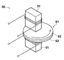
- master carriers 65 and 66 having a concavo-convex pattern corresponding to information to be transferred to a magnetic recording medium 64 (slave medium) on the surface are prepared, and a holder plate 62 and 63, a master unit 65 is bonded on the cushion member 67 bonded to the holder plate 62, and the master carrier 66 is bonded on the cushion member 68 bonded to the holder plate 63.
- an external magnetic field is applied by a magnetic field applying device 51 disposed on both sides of the holder unit 61 while rotating the closed holder unit 61 so that the master carriers 65 and 66 are in close contact with both surfaces of the slave medium 64.
- This magnetic transfer can record statically without changing the relative positions of the master carrier and slave medium, enables accurate preformat recording, and also requires a very short recording time. It has the advantage of being.
- the master carrier in which the master carrier is brought into close contact with the slave medium and the information on the surface of the master carrier is transferred to the slave medium, it is important to realize uniform adhesion between the master carrier and the slave medium.
- the master carrier is bonded to a base member (holder plate or the like) using an adhesive elastic member (cushion member) containing a base material.
- a master assembly (a structure including a base member, a cushion member, and a master carrier) is formed.
- the present invention has been made in response to the above-mentioned demands.
- a master assembly and a manufacturing method thereof a recording medium magnetically transferred using the master assembly while ensuring the adhesion between the master carrier and the slave medium.
- An object of the present invention is to provide a master assembly capable of reducing RRO to less than 60 nm and a manufacturing method thereof.
- the present invention includes a base member and a cushion member bonded to the base member on one surface, and in the carrier fixing member used for manufacturing the master assembly and the manufacturing method thereof, the adhesion between the master carrier and the slave medium is improved.
- An object of the present invention is to provide a carrier fixing member capable of reducing RRO of a recording medium magnetically transferred using a master assembly using the carrier fixing member to less than 60 nm and a method for manufacturing the same. It is what.
- a method for manufacturing a master assembly includes: A base member, a cushion member composed of an elastic member provided with an adhesive on both sides, and a master carrier having a concavo-convex pattern corresponding to transfer information on one surface, the master carrier being a base via the cushion member
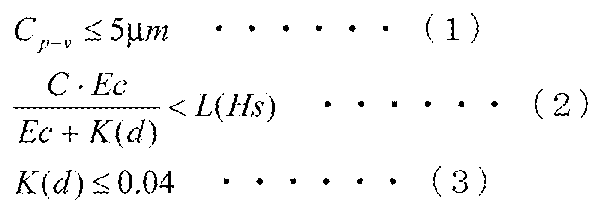
- a base member and a cushion member that is bonded to the base member on one surface, and the other surface that is bonded to the master carrier satisfy the following formulas (1) to (3) with respect to the surface shape are prepared.
- a master carrier having a predetermined thickness is adhered to the other surface of the cushion member.
- C p ⁇ v is the maximum height of the surface shape obtained by measuring the surface shape over the entire other surface of the cushion member with the cushion member bonded to the base member on the one surface. The difference between the value and the minimum value (unit: ⁇ m)
- C is an X-direction and a Y-direction that are orthogonal to each other on the other surface of the cushion member based on the result of the measurement relating to the surface shape, and an inclination in the X direction at each position on the other surface.
- Ec represents the Young's modulus (unit: GPa) of the elastic member
- K (d) represents an amount (unit: GPa) corresponding to the bending rigidity of the master carrier, and is a value obtained by the following formula (4)
- L (Hs) represents an upper limit value in the formula (1), and is a value obtained by the following formula (5).
- Em represents the Young's modulus (unit: GPa) of the master carrier
- d represents the thickness (unit: mm) of the master carrier
- Hs represents the rubber hardness of the elastic member.
- the above formula (2) is preferably the following formula (2a).
- a cushion member by performing a cutting process that draws the blade relative to the cushion sheet and cutting the cushion member from the cushion sheet.
- the angle formed by the blade and the cushion sheet is 14 It is preferable that the drawing process is performed under the condition that the angle is ⁇ 22 degrees and the relative moving speed of the blade with respect to the cushion sheet is 20 to 40 cm / s.
- the elastic member has a surface subjected to diamond turning.
- the master assembly is: A base member, a cushion member composed of an elastic member provided with an adhesive on both sides, and a master carrier having a concavo-convex pattern corresponding to transfer information on one surface, the master carrier being a base via the cushion member
- the pattern forming surface of the concavo-convex pattern of the master carrier satisfies the following formulas (6) and (7) with respect to the surface shape in a state where the master carrier is bonded to the cushion member.
- M p ⁇ v is the height of the surface shape obtained by measuring the surface shape over the entire pattern forming surface of the master carrier in a state where the master carrier is bonded to the cushion member.
- M is the X direction orthogonal to each other on the pattern forming surface of the master carrier and Of the magnitudes of all X-direction inclinations and all Y-direction inclinations obtained by arbitrarily setting the Y-direction and obtaining the X-direction inclination and the Y-direction inclination at the respective positions on the pattern formation surface
- the maximum value (unit: ⁇ m / mm) is represented.
- the carrier fixing member according to the present invention is: In a carrier fixing member comprising a base member and a cushion member composed of an elastic member provided with an adhesive on both sides, and a master carrier having a concavo-convex pattern corresponding to transfer information on one side, The cushion member is bonded to the base member on one side, The other surface of the cushion member bonded to the master carrier satisfies the above formulas (1) to (3) with respect to the surface shape.
- the elastic member has a surface subjected to diamond turning.
- the manufacturing method of the carrier fixing member according to the present invention includes: In the method of manufacturing a carrier fixing member that adheres one surface of a cushion member composed of an elastic member to which an adhesive is applied to both surfaces to a base member, The cushion member is adjusted so that the other surface of the cushion member bonded to the master carrier having the uneven pattern corresponding to the transfer information on one surface satisfies the above formulas (1) to (3) with respect to the surface shape.
- the base member is bonded to the base sheet, and a cutting process is performed to draw a blade relative to the cushion sheet, and the cushion member is cut from the cushion sheet.
- the angle between the blade and the cushion sheet is 14 to 22 degrees
- the relative movement speed of the blade with respect to the cushion sheet is 20 to 40 cm / s, It is preferable to perform a drawing process.
- the manufacturing method of a master assembly is a manufacturing method of a master assembly that performs magnetic transfer by bringing a concavo-convex pattern and a slave medium into close contact with each other, particularly with a base member and a cushion member bonded to the base member on one surface.
- a cushion member satisfying the above formulas (1) to (3) with respect to the surface shape of the other surface bonded to the master carrier is prepared, and the master carrier having a predetermined thickness is placed on the other side of the cushion member. Since the master carrier is adhered to the surface, the flatness when the master carrier is adhered to the carrier fixing member can be improved, and the lateral elongation when the master carrier and the slave medium are brought into close contact during magnetic transfer can be suppressed. Therefore, in the master assembly, it is possible to reduce the RRO of the magnetically transferred recording medium to less than 60 nm while ensuring the adhesion between the master carrier and the slave medium.
- the master assembly according to the present invention is a master assembly that performs magnetic transfer by bringing a concave / convex pattern and a slave medium into close contact with each other, and the pattern formation surface of the concave / convex pattern of the master carrier is bonded to the cushion member. Therefore, the flatness when the master carrier is bonded to the carrier fixing member is improved, and the master carrier and the slave medium are brought into close contact during magnetic transfer. It is possible to suppress lateral elongation at the time. Therefore, in the master assembly, it is possible to reduce the RRO of the magnetically transferred recording medium to less than 60 nm while ensuring the adhesion between the master carrier and the slave medium.
- the carrier fixing member and the manufacturing method thereof according to the present invention are the carrier fixing member to which a master carrier having a concavo-convex pattern corresponding to transfer information is bonded on one surface, and the cushion member is attached to the base member on one surface. Since the other surface of the cushion member bonded to the master carrier satisfies the above formulas (1) to (3) with respect to the surface shape, the master carrier is bonded to the carrier fixing member. The flatness at the time can be improved, and the lateral elongation when the master carrier and the slave medium are brought into close contact during magnetic transfer can be suppressed. Therefore, in the master assembly manufactured using the carrier fixing member and the manufacturing method thereof, the RRO of the magnetically transferred recording medium is reduced to less than 60 nm while ensuring the adhesion between the master carrier and the slave medium. Is possible.
- the manufacturing method of the master assembly 1 according to the present embodiment includes a master carrier having a predetermined thickness, a base member, and a cushion member bonded to the base member on one surface, and is bonded to the master carrier.
- a cushion member satisfying the above formulas (1) to (3) with respect to the surface shape of the other surface is prepared, and the master carrier is bonded to the cushion member.
- the master assembly 1 manufactured by the above method includes a base member, a cushion member composed of an elastic member provided with an adhesive on both sides, and a master carrier having a concavo-convex pattern corresponding to transfer information on one side
- the master carrier is fixed to the base member via the cushion member and magnetic transfer is performed by bringing the concave and convex pattern into close contact with the slave medium
- the pattern forming surface of the concave and convex pattern of the master carrier is In the state of being bonded to the cushion member, the above formula (6) and formula (7) are satisfied with respect to the surface shape.
- the carrier fixing member of the present invention includes the base member and a cushion member bonded to the base member on one surface.
- the above formula 2 is preferably the above formula 2a from the viewpoint of further reducing the RRO of the magnetically transferred recording medium.
- FIG. 1 is a schematic cross-sectional view showing a master assembly manufactured according to the present embodiment.
- a holder unit type master assembly 1 as shown in FIG. 1 can be manufactured, for example.
- a slave medium 40 is also shown for convenience.
- the holder unit type master assembly 1 of the present embodiment includes a master assembly lower part 10 and an upper part 11.
- the master assembly lower part 10 includes a base member 2 (holder plate), a first carrier fixing member including an O-ring 5 and a cushion member 27a, and a master carrier 30a.
- the master assembly upper part 11 is constituted by a second carrier fixing member composed of a base member 3 (holder plate) and a cushion member 27b, and a master carrier 30b.
- the master assembly 1 according to this embodiment includes two base members 2 and 3, two cushion members 27a and 27b bonded to the respective base members on one surface, and the cushion members.
- the structure includes two master carriers 30a and 30b bonded to the other surface, and performs magnetic transfer by closely contacting the slave medium 40 with the concave and convex patterns of the master carriers 30a and 30b. .
- the first and second carrier fixing members are the carrier fixing members of the present invention, respectively, and include base members 2 and 3 and cushion members 27a and 27b.
- the cushion members 27a and 27b are attached to the base members 2 and 3, respectively.
- the other surfaces of the cushion members 27a and 27b satisfy the above formulas (1) to (3) with respect to the surface shape in a state where the surfaces are bonded to each other.
- the base members 2 and 3 are provided so as to be movable in the axial direction, and are opened / closed by an opening / closing mechanism (not shown).
- the base members 2 and 3 are disk-shaped, have a circular plane larger than the outer diameter of the master carriers 30a and 30b, and the sheet-like cushion members 27a and 27b are bonded to the center of the surface by their adhesiveness. Yes.
- the master carriers 30a and 30b are fixed on the cushion members 27a and 27b by adhesion or the like.
- a center core 6 inserted through the central openings of the master carriers 30a and 30b and the slave medium 40 protrudes, whereby the slave medium 40 is detachably held.
- the base members 2 and 3 are linked to a rotation mechanism (not shown) and are integrally rotated.
- the master assembly 1 improves the adhesion between the slave medium 40 and the master carriers 30a and 30b by vacuuming the air in the internal space formed by the sliding contact between the base members 2 and 3 and reducing the internal pressure. For this reason, it is connected to vacuum suction means (not shown) via suction paths 7 and 8.
- the suction passages 7 and 8 are provided in the base member 2 so as to have openings in the inner space of the inner peripheral portion and the outer peripheral portion from the master carrier 30a, for example, on the inner peripheral side from the flange portion 4.
- vacuum suction of air by the vacuum suction means By vacuum suction of air by the vacuum suction means, it is brought into close contact with the slave medium 40 so as to be sandwiched between the master carriers 30a and 30b, and the internal space formed when the base members 2 and 3 are fitted to a predetermined degree of vacuum. Can be controlled.
- the material of the base members 2 and 3 can be glass, metal or the like, and is not particularly limited. However, in order to realize a good magnetic field application, it is preferable to use a nonmagnetic material such as stainless steel.
- the cushion members 27a and 27b are made of an elastic material having an elastic property, allow the elastic deformation of the master carrier when a contact pressure is applied, and improve the adhesion by matching the surface shapes of the slave medium 40 and the master carriers 30a and 30b. When the adhesive force is released, it has a characteristic of restoring to the original state.
- the cushion members 27a and 27b satisfy the above formulas (1) to (3) with respect to the surface shape in the state where the cushion members 27a and 27b are respectively bonded to the base members 2 and 3 on one side.
- the cushion members 27a and 27b can be constituted by, for example, elastic members 23a and 23b to which adhesives (21a, 21b, 25a and 25b) are applied on both surfaces.
- the material, thickness, and the like of the elastic member are preferably set such that the amount of deformation in the pressing direction of the elastic member due to the applied pressure is in the range of 5 ⁇ m to 500 ⁇ m.
- the elastic modulus (Young's modulus) of the elastic member is preferably 3.4 MPa to 42.9 MPa.
- the rubber hardness of the elastic member is high, the lateral extension of the master carrier at the time of magnetic transfer is suppressed, so even if M related to the height of the surface shape of the master carrier is large, it can be contained in a certain RRO. On the contrary, if the rubber hardness of the elastic member is low, the lateral elongation of the master carrier at the time of magnetic transfer becomes large.
- the rubber hardness of the elastic member used in the present invention is preferably as high as possible, with rubber hardness of 60 to 95 being preferred, and rubber hardness of 70 to 80 being more preferred. If the rubber hardness is 60 or less, it is not preferable because it is difficult to obtain an elastic body having a highly uniform thickness.
- the rubber hardness is 95 or more, the adhesion between the master carrier and the slave medium at the time of magnetic transfer is lowered and a transfer signal is lost. It is not preferable.
- the rubber hardness is a value measured by a Shore A type hardness meter.
- the material of the elastic member is preferably urethane rubber, nitrile butadiene rubber, fluorine rubber, or the like.
- the elastic member has a diamond turning process applied to the surface of the elastic member.
- the height of the surface shape of the cushion member in the above formulas (1) and (2) is determined by measuring the surface of the cushion member bonded to the base member with a laser scanning type surface shape measuring device (Keyence Corporation). It is a value obtained by measurement by (manufactured). The same applies to the height of the surface shape of the master carrier when the master carrier is bonded to the cushion member in the above formulas (5) and (6).
- the thickness d of the master carrier is the length from the pattern forming surface (the surface along the top surface of the convex portion of the concavo-convex pattern) of the master carriers 30a and 30b to the opposite surface.
- the cushion members 27a and 27b can be formed by cutting a cushion member having a desired size and shape from a cushion sheet having a predetermined size. Further, when the cushion members 27a and 27b are laminated using an elastic member and an adhesive material, it is preferable to first provide the adhesive material on the elastic sheet and then cut out the cushion member having a desired size and shape from the elastic sheet. .
- the method for producing the cushion sheet is described in detail in Patent Document 1. As a method of cutting out a cushion member having a desired size and shape from the cushion sheet, laser processing, water jet processing, and drawing processing may be applied in addition to punching processing. In particular, in order to prevent the shape of the end of the cushion member from rising, it is preferable to use a drawing process.
- the cushion member formed by combining the elastic body and the adhesive material is fixed on the base member, the cushion member is used to measure the height of the surface shape of the cushion member fixed to the base member with reference to the surface of the base member.
- C over the entire surface of when the difference between the maximum value and the minimum value of the height of the surface shape of the cushion member has a C p-v, C p- v is preferably not more than 5um. This is because if it is 5 ⁇ m or more, the adhesion between the master carrier and the slave medium is lowered.
- the punching process is a processing method in which the cutting target member is subjected to a shearing process when the cutting edge enters perpendicularly to the processing target member surface.
- the cutting edge moves so as to cross each member.
- the blade edge first enters the upper adhesive material layer, then the blade edge enters the elastic member, and then the lower adhesive material layer
- the cutting edge intrudes into.
- the blade edge enters each member and is sheared when the member reaches the limit of deformation while being deformed. After the end of shearing, the cutting edge moves to the opposite side of the penetration direction, the blade is taken out, and the processing is completed.
- Punching can be performed in a short time as a processing means, and productivity is good.
- the thickness of the cushion member is desired to be uniform after processing.
- the inventors have found that the thickness of the cushion member locally changes at the processed end. It was found that this is because when the blade edge penetrates into the upper adhesive material layer, a part of the adhesive material adheres to the side surface of the blade edge and the adhesive material is stretched along with the movement of the blade edge. As a result, the thickness of the cushion member at the processed end is increased.
- the blade edge angle, the coating for preventing adhesion of the adhesive material, the moving speed of the blade edge, the fixing of the cushion member surface, the temperature of the cushion member during punching, and the like were examined as appropriate.
- none of the countermeasures can completely eliminate the adhesion of the adhesive material to the cutting edge, and it is difficult to suppress an increase in the thickness of the cushion member at the processed end.
- the laser processing without physical contact was also studied, but due to thermal alteration at the processing end, the thickness at the processing end increased more than when punching. Furthermore, water jet cutting was also examined from the viewpoint of preventing adhesion of the adhesive layer, but the phenomenon of the adhesive layer being stretched by water pressure was not reduced, and the thickness at the processing edge increased as in the case of punching. Oops. Further, in the water jet cutting process, the processing dimensional accuracy is poor, and the desired inner and outer diameters cannot be obtained.
- the drawing process is a process in which the cutting target member is cut by moving the cutting edge relative to the processing target member in a direction perpendicular to the penetrating direction after the cutting edge is inserted perpendicular to the surface of the processing target member. It is a method.
- the same type of member always strikes each part of the blade edge during the cutting process, and each member being cut
- the conditions for cutting are characterized in that the same conditions can be maintained for each member.
- the punching process is performed by making the blade edge make a round on the inner periphery or the outer periphery while the punching process is performed simultaneously on the inner periphery and the outer periphery by the punching blade.
- the deformation in the thickness direction of the cushion member at the processed end can be minimized.
- the stretching of the adhesive material layer observed in the punching process or other processes does not occur in the thickness direction of the cushion member in this drawing process, but occurs in a direction parallel to the adhesive material layer. That is, the thickness of the cushion member at the processed end does not increase in the drawing process.
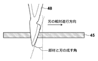
- the cutting edge In the processing of the cushion member used in the present invention, the cutting edge needs to be thin to some extent because of circular processing. Therefore, it has been found that the mechanical rigidity of the cutting edge is difficult to obtain, the cutting edge is likely to be shaken during the cutting process, and the desired machining dimensional accuracy may not be obtained. In this regard, it has been found that the desired machining dimensional accuracy can be obtained by adjusting the angle of the blade with respect to the workpiece and the relative movement speed of the blade edge. More specifically, in the processing of the cushion member used in the present invention, the angle formed by the blade and the cushion member is between 14 and 22 degrees, and the relative movement speed between the blade and the cushion member during processing is 20 degrees. It is preferably ⁇ 40 cm / sec. In addition, for the cutting process of the cushion member used in the present invention, a replaceable knife knife No. made by Futaba Corporation. 19 (made of special steel) was used. The angle between the member and the blade is defined as shown in FIG.
- the cushion member manufacturing method according to the present embodiment is relative to the cushion sheet 45 in the cushion member manufacturing method for bonding and fixing the base member and the master carrier, for example, as shown in FIG.
- the cushion member is cut out from the cushion sheet 45 by performing a drawing process of drawing the blade 48.
- the blade 48 is fixed, and the cushion sheet 45 is rotated in one direction around the axis perpendicular to the seat surface while being in contact with the blade 48, thereby realizing relative movement. It is preferable to do.
- the master carrier is a structure having a desired concavo-convex pattern shape on the surface, and is a master for magnetic transfer for transferring a magnetization pattern corresponding to the shape of the concavo-convex pattern to a slave medium.
- the master carrier is, for example, a photoresist coated on a circular substrate made of quartz glass or the like with a smooth surface by a spin coater or the like, and after pre-baking, a laser beam (or electron beam) modulated in accordance with a signal to be recorded is applied.
- the thickness of the master carrier is preferably 200 nm or more and less than 600 nm. As for the lower limit, if the thickness of the master carrier is thinner than 200 nm, sufficient rigidity of the master carrier cannot be secured, and the overall shape of the master carrier is also affected by slight distortion of the underlying cushion member.
- the overall flatness of the film is reduced.
- the upper limit when the thickness of the master carrier is 600 nm or more, the master carrier is too rigid, and when the master carrier is in close contact with the slave medium, the overall shape of the master carrier is deformed and the surface shape of the slave medium is deformed. This is because the adhesion between the master carrier and the slave medium is lowered.
- RRO is a rotational synchronization component of an error that occurs when positioning a magnetic head.
- RRO rotates a certain track recorded on the medium with respect to a perfect circle centered on the rotation center of the medium. This refers to the position difference that deviates from the true circle.
- RRO is measured by demodulating the cylinder number and burst signal included in the servo signal for one round of the medium.
- the inventors have found that the surface shape of the master carrier bonded on the master assembly and the lateral elongation of the master carrier when the master carrier and the magnetic medium are in close contact with each other during magnetic transfer contribute to the size of the RRO. It was.
- the master carrier bonded on the master assembly has a certain surface shape height, for example, with the surface of the base member as a reference for the height.
- the height distribution of the master carrier is determined by the thickness unevenness of the master carrier itself, the bonding shape of the cushion member, and the surface shape of the base member surface.
- the master carrier extends laterally from the initial shape formed when the master carrier is bonded to the master assembly, and from the initial shape when the magnetic carrier is closely attached.
- the uneven pattern formed on the master carrier also follows the master carrier and extends laterally. Due to the close contact between the master carrier and the slave medium, the concave / convex pattern that should be transferred without deformation is transferred to the slave medium in a state of being laterally extended along with the lateral extension of the master carrier. Is reflected in the magnetic transfer signal as RRO.
- This lateral elongation occurs due to the Poisson's ratio of the master carrier itself and the force that pulls the master carrier when the elastic member of the cushion member is laterally stretched.
- the lateral elongation of the master carrier does not necessarily become isotropic, and generally has a direction that is easy to stretch and a direction that is difficult to stretch. Therefore, the lateral elongation of the master carrier affects the increase in RRO.
- the dominant factor is the lateral elongation of the elastic member. Therefore, if the lateral elongation of the elastic member is small, the lateral elongation of the master carrier is also small, and as a result, an increase in RRO can be suppressed.
- the thickness of the master carrier, the Young's modulus of the master carrier, the Young's modulus and rubber hardness of the elastic body used for the cushion member, and the surface shape of the cushion member when fixed on the master assembly It was found that the surface shape of the master carrier bonded onto the master assembly and the lateral elongation of the master carrier at the time of magnetic transfer are governed, resulting in an increase in RRO.
- the height of the surface shape of the master carrier bonded on the master assembly is the relationship between the height of the surface shape when the cushion member is fixed on the base member, the bending rigidity of the master carrier, and the Young's modulus of the cushion member. Determined by When the cushion member is bonded onto the base member, the height of the surface shape of the cushion member is determined by the influence of the surface shape of the surface of the base member, the thickness distribution of the cushion member, and the shape of the processed end portion of the cushion member. In general, it is difficult to make the height of the surface shape of the cushion member completely uniform, and the height distribution of a certain surface shape is present.
- the master assembly is obtained by bonding the master carrier to the cushion member fixed on the base member.
- the height of the surface shape of the master carrier bonded to the master assembly is the height of the surface shape of the cushion member. to be influenced.
- the height of the surface shape of the master carrier is determined by the balance between the force by which the cushion member pulls the master carrier to conform to the shape of the cushion member and the force with which the master carrier can withstand bending. That is, the height of the surface shape when the cushion member is fixed on the base member and the height of the surface shape of the master carrier bonded on the master assembly due to the relationship between the bending rigidity of the master carrier and the Young's modulus of the cushion member. It is determined.
- the surface shape is measured over the entire other surface of the cushion member, and the cushion member is based on the result of the measurement related to the surface shape.
- All X directions obtained by arbitrarily setting the X direction and the Y direction orthogonal to each other on the other surface, and obtaining the X direction inclination and the Y direction inclination at the respective positions of the other surface C (unit: ⁇ m / mm), master carrier thickness d (um), master carrier Young's modulus Em (GPa), When the Young's modulus is Ec (GPa), it is understood that the maximum value M of the height gradient of the surface shape of the master carrier fixed on the master assembly can be obtained by the following formula (8). It was.
- K (d) is an amount corresponding to the bending rigidity of the master carrier obtained by the following equation (9), and is an amount proportional to the cube of the Young's modulus Em of the master carrier and the thickness d of the master carrier. is there.
- the amount K (d) corresponding to the bending rigidity of the master carrier is preferably 0.04 GPa or less.
- the above equation (8) can be derived from the balance between the force with which the cushion member pulls the master carrier in the shape of the cushion member and the force with which the master carrier can withstand bending.
- the cushion member has an initial deformed state, and when the master carrier is bonded onto the cushion member, the cushion member starts to be deformed to adhere to the shape of the master carrier by adhering to the master carrier.
- the cushion member When the cushion member is deformed so as to approach the shape of the master carrier, the cushion member generates a restoring force with a Young's modulus Ec as a spring constant, and a force for pulling the master carrier is generated. In this situation, the master carrier tries to follow the shape of the cushion member by the attractive force from the cushion member.
- the master carrier since the master carrier has bending rigidity, it exerts a resistance against the attractive force from the cushion member.
- the final deformation state of the master carrier and the cushion member is determined at a position where the attractive force from the cushion member and the drag force of the master carrier are balanced.
- the above relational expression was derived by organizing the equation representing the balance of forces.
- the cushion member is a composite member composed of an elastic body and an adhesive material.
- the Young's modulus of the adhesive material is negligibly lower than that of the elastic body, and the thickness of the adhesive material is sufficiently thin so that the balance of force is sufficient. Since the contribution was small, the contribution of the adhesive was ignored.
- the coefficient of 9.0 ⁇ 10 ⁇ 4 in the formula (9) is a constant obtained experimentally. Specifically, the coefficient of 9.0 ⁇ 10 ⁇ 4 is determined by the shape of the master carrier and the constraint condition of the master carrier as the second moment of the cross section.
- the master carrier in the present invention forms a master assembly in a state of being bonded to the cushion member. Based on this constraint condition, as shown in Table 1, the surface shape of the master carrier when the master carrier is bonded using the cushion members having the same C regarding the height of the surface shape of the cushion member and different thicknesses.
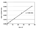
- the relationship of M with respect to the height is examined, the plot on the graph shown in FIG. 3 is approximated by the least square method, and the proportionality coefficient becomes 9.0 ⁇ 10 ⁇ 4 (mm ⁇ 3 ) from the slope in the experiment. Asked.
- the RRO is determined by M related to the height of the surface shape of the master carrier and the lateral elongation of the master carrier during magnetic transfer.
- the allowable amount of M related to the height of the surface shape of the master carrier is determined by the degree of lateral elongation of the master carrier.
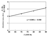
- the above equation (10) was obtained experimentally by examining the relationship between the allowable amount L (Hs) of M and Hs regarding the height of the surface shape of the master carrier. Specifically, as shown in Table 2, after the master carrier having the same thickness is bonded to a cushion member with different rubber hardness and magnetic transfer is performed, the index when the RRO reaches an allowable amount of 60 nm M was confirmed experimentally. The results obtained in the experiment were plotted on a graph as shown in FIG. 4, and an approximated curve was prepared by the least square method. As a result, it was found that L (Hs) satisfies the relationship of the above formula (10) with respect to Hs within the scope of application of the present invention.
- the manufacturing method of the master assembly according to the present invention is such that the base member and the base member are bonded to one side in particular in the manufacturing of the master assembly that performs magnetic transfer by bringing the uneven pattern and the slave medium into close contact with each other.
- a cushion member, the other surface of which is bonded to the master carrier, is prepared so as to satisfy the above formulas (1) to (3) with respect to the surface shape, and the master carrier having a predetermined thickness is used as the cushion member. Adhering to the other surface improves the flatness when the master carrier is adhered to the carrier fixing member, and suppresses lateral elongation when the master carrier and the slave medium are brought into close contact during magnetic transfer. Can do. Therefore, in the master assembly, it is possible to reduce the RRO of the magnetically transferred recording medium to less than 60 nm while ensuring the adhesion between the master carrier and the slave medium.
- the master assembly according to the present invention is a master assembly that performs magnetic transfer by bringing a concave / convex pattern and a slave medium into close contact with each other, and the pattern formation surface of the concave / convex pattern of the master carrier is bonded to the cushion member. Therefore, the flatness when the master carrier is bonded to the carrier fixing member is improved, and the master carrier and the slave medium are brought into close contact during magnetic transfer. It is possible to suppress lateral elongation at the time. Therefore, in the master assembly, it is possible to reduce the RRO of the magnetically transferred recording medium to less than 60 nm while ensuring the adhesion between the master carrier and the slave medium.
- the carrier fixing member and the manufacturing method thereof according to the present invention are the carrier fixing member to which a master carrier having a concavo-convex pattern corresponding to transfer information is bonded on one side, and the cushion member is on one side of the base member. Since the other surface of the cushion member bonded to the master carrier satisfies the above formulas (1) to (3) with respect to the surface shape, the master carrier is bonded to the carrier fixing member. The flatness at the time can be improved, and the lateral elongation when the master carrier and the slave medium are brought into close contact during magnetic transfer can be suppressed. Therefore, in the master assembly manufactured using the carrier fixing member and the manufacturing method thereof, the RRO of the magnetically transferred recording medium is reduced to less than 60 nm while ensuring the adhesion between the master carrier and the slave medium. Is possible.
- Examples of the method for manufacturing a master assembly according to the present invention are shown below.
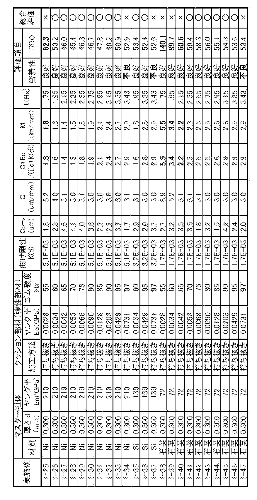
- ⁇ Manufacture of master assembly> Each manufacturing condition of the master assembly shown in Tables 3 and 4 (master carrier material, master carrier thickness, master carrier Young's modulus, cushion member cutting method, cushion member Young's modulus, elastic member rubber hardness ), Examples 1-1 to 1-47 of the manufacturing method of the master assembly were carried out.
- “DT processing” means diamond turning processing.
- the master assembly manufactured according to these examples was used to evaluate the adhesion to the slave medium and the RRO of the magnetically transferred recording medium. And in two evaluation items, when the adhesiveness was favorable and RRO was less than 60 nm, comprehensive evaluation was performed as the subject of this invention was able to be solved.
- the master assembly manufactured thereby was magnetically transferred while ensuring the adhesion between the master carrier and the slave medium. It has been demonstrated that the RRO of the recording medium can be reduced to less than 60 nm.
- Table 5 is a table showing the results of the example in the case where the cutting process is adopted instead of the punching process as the cushion member cutting process in Example 1-2. In Examples 2-1 to 2-9, the moving speed and the blade angle in the drawing process were changed.
Landscapes
- Magnetic Record Carriers (AREA)
Abstract
【課題】凹凸パターンとスレーブ媒体(40)とを密着させて磁気転写を行うマスターアッセンブリ(1)の製造方法において、ベース部材(2)と、ベース部材(2)に一方の面で接着されたクッション部材(27a)であって、マスター担体(30a)と接着される他方の面が表面形状に関して式1から式3を満たすクッション部材(27a)とを用意し、所定の厚さを有するマスター担体(30a)をクッション部材(27a)の上記他方の面に接着させる。
Description
本発明は、情報記録媒体にフォーマット情報等を転写するためにマスター担体をベース部材に固定してなるマスターアッセンブリの製造方法およびマスターアッセンブリ、並びに、担体固定部材および担体固定部材の製造方法に関するものである。
ハードディスク装置やフレキシブルディスク装置等に用いられる高密度の磁気記録媒体(磁気ディスク媒体など)にプリフォーマット記録を正確にかつ効率よく行う方法として、磁気転写が知られている。
磁気転写は、例えば図5および図6に示すように、磁気記録媒体64(スレーブ媒体)に転写すべき情報に対応する凹凸パターンを表面に有するマスター担体65および66を用意し、ホルダープレート62および63からなるホルダーユニット61を用意し、ホルダープレート62に接着されたクッション部材67上にマスター担体65を接着し、同様にホルダープレート63に接着されたクッション部材68上にマスター担体66を接着し、磁気転写装置50において、スレーブ媒体64の両面にマスター担体65および66を密着させるように閉じたホルダーユニット61を回転させつつ、このホルダーユニット61の両側に配設された磁界印加装置51によって外部磁界を印加して、マスター担体65および66が担持する磁気パターンをスレーブ媒体64に転写することにより行われる。この磁気転写は、マスター担体とスレーブ媒体との相対的な位置を変化させることなく静的に記録を行うことができ、正確なプリフォーマット記録が可能であり、しかも記録に要する時間も極めて短時間であるという利点を有している。
マスター担体をスレーブ媒体に密着させ、マスター担体表面の情報をスレーブ媒体に転写する上記のような磁気転写装置においては、マスター担体とスレーブ媒体との均一な密着性を実現することが重要である。
そこで、マスター担体とスレーブ媒体との密着性を向上させるために、例えば特許文献1は、マスター担体を粘着性で基材入りの弾性部品(クッション部材)を用いベース部材(ホルダープレート等)に接着させて、マスターアッセンブリ(ベース部材、クッション部材およびマスター担体からなる構造体)を形成することを開示している。
近年磁気記録媒体の高密度化に伴い、磁気記録の正確性に対する要求がさらに高まっている。これは、例えばトラックピッチが100nm程度に高密度化された磁気記録媒体において、磁気記録媒体の回転駆動における繰り返し揺れを示すRRO(Repeatable Run Out)の問題が顕在化するためである。一般的に、トラックピッチが100nm程度の場合、RROは60nm未満であることが要求される。しかしながら、特許文献1の方法では、上記のようなマスターアッセンブリを用いてマスター担体とスレーブ媒体との密着性を向上させることはできるものの、磁気転写された磁気記録媒体のRROを低減することは難しい。そこで、マスター担体とスレーブ媒体との密着性を確保しつつ、磁気記録媒体のRROを60nm未満にまで低減することができる手法の開発が望まれている。
本発明は上記要望に応えてなされたものであり、マスターアッセンブリおよびその製造方法において、マスター担体とスレーブ媒体との密着性を確保しつつ、そのマスターアッセンブリを使用して磁気転写された記録媒体のRROを60nm未満にまで低減することを可能とするマスターアッセンブリおよびその製造方法を提供することを目的とするものである。
さらに本発明は、ベース部材、およびベース部材と一方の面で接着されたクッション部材を備え、マスターアッセンブリの製造に用いられる担体固定部材およびその製造方法において、マスター担体とスレーブ媒体との密着性を確保しつつ、当該担体固定部材を用いたマスターアッセンブリを使用して磁気転写された記録媒体のRROを60nm未満にまで低減することを可能とする担体固定部材およびその製造方法を提供することを目的とするものである。
上記課題を解決するために、本発明に係るマスターアッセンブリの製造方法は、
ベース部材と、両面に粘着剤が付与された弾性部材から構成されるクッション部材と、一方の面に転写情報に対応する凹凸パターンを有するマスター担体とを備え、マスター担体がクッション部材を介してベース部材に固定された状態で、凹凸パターンとスレーブ媒体とを密着させて磁気転写を行うマスターアッセンブリの製造方法において、
ベース部材と、ベース部材に一方の面で接着されたクッション部材であって、マスター担体と接着される他方の面が表面形状に関して下記式(1)から式(3)を満たすクッション部材とを用意し、
所定の厚さを有するマスター担体をクッション部材の上記他方の面に接着させることを特徴とするものである。
ベース部材と、両面に粘着剤が付与された弾性部材から構成されるクッション部材と、一方の面に転写情報に対応する凹凸パターンを有するマスター担体とを備え、マスター担体がクッション部材を介してベース部材に固定された状態で、凹凸パターンとスレーブ媒体とを密着させて磁気転写を行うマスターアッセンブリの製造方法において、
ベース部材と、ベース部材に一方の面で接着されたクッション部材であって、マスター担体と接着される他方の面が表面形状に関して下記式(1)から式(3)を満たすクッション部材とを用意し、
所定の厚さを有するマスター担体をクッション部材の上記他方の面に接着させることを特徴とするものである。

なお、式(1)において、
Cp-vは、クッション部材が上記一方の面でベース部材に接着された状態で、クッション部材の上記他方の面の全面にわたり表面形状を測定して得られた、表面形状の高さの最大値と最小値の差(単位:μm)を表し、
式(2)において、
Cは、表面形状に関する上記測定の結果に基づいて、クッション部材の上記他方の面上で互いに直交するX方向およびY方向を任意に設定し、上記他方の面のそれぞれの位置においてX方向の傾きおよびY方向の傾きを求めて得られた、すべてのX方向の傾きおよびすべてのY方向の傾きの大きさのうち最大値(単位:μm/mm)を表し、
Ecは、弾性部材のヤング率(単位:GPa)を表し、
K(d)は、マスター担体の曲げ剛性に相当する量(単位:GPa)を表し、下記式(4)で得られる値であり、
L(Hs)は、式(1)における上限値を表し、下記式(5)で得られる値である。
Cp-vは、クッション部材が上記一方の面でベース部材に接着された状態で、クッション部材の上記他方の面の全面にわたり表面形状を測定して得られた、表面形状の高さの最大値と最小値の差(単位:μm)を表し、
式(2)において、
Cは、表面形状に関する上記測定の結果に基づいて、クッション部材の上記他方の面上で互いに直交するX方向およびY方向を任意に設定し、上記他方の面のそれぞれの位置においてX方向の傾きおよびY方向の傾きを求めて得られた、すべてのX方向の傾きおよびすべてのY方向の傾きの大きさのうち最大値(単位:μm/mm)を表し、
Ecは、弾性部材のヤング率(単位:GPa)を表し、
K(d)は、マスター担体の曲げ剛性に相当する量(単位:GPa)を表し、下記式(4)で得られる値であり、
L(Hs)は、式(1)における上限値を表し、下記式(5)で得られる値である。

なお、式(4)において、
Emは、マスター担体のヤング率(単位:GPa)を表し、
dは、マスター担体の厚さ(単位:mm)を表し、
式(5)において、
Hsは、弾性部材のゴム硬度を表す。)
Emは、マスター担体のヤング率(単位:GPa)を表し、
dは、マスター担体の厚さ(単位:mm)を表し、
式(5)において、
Hsは、弾性部材のゴム硬度を表す。)
さらに、本発明に係るマスターアッセンブリの製造方法において、上記式(2)が、下記式(2a)であることが好ましい。

さらに、クッションシートに対して相対的に刃を引く引切り加工を行い、クッションシートからクッション部材を切り取ることにより、クッション部材を得ることが好ましく、この場合、刃とクッションシートとの成す角度が14~22度であり、クッションシートに対する刃の相対的な移動速度が20~40cm/sである条件で、引切り加工を行うことが好ましい。
さらに、弾性部材は、表面にダイヤモンドターニング加工が施されているものであることが好ましい。
さらに、本発明に係るマスターアッセンブリは、
ベース部材と、両面に粘着剤が付与された弾性部材から構成されるクッション部材と、一方の面に転写情報に対応する凹凸パターンを有するマスター担体とを備え、マスター担体がクッション部材を介してベース部材に固定された状態で、凹凸パターンとスレーブ媒体とを密着させて磁気転写を行うマスターアッセンブリにおいて、
マスター担体の凹凸パターンのパターン形成面が、マスター担体がクッション部材に接着された状態において、表面形状に関し下記式(6)および式(7)を満たすものであることを特徴とするものである。
ベース部材と、両面に粘着剤が付与された弾性部材から構成されるクッション部材と、一方の面に転写情報に対応する凹凸パターンを有するマスター担体とを備え、マスター担体がクッション部材を介してベース部材に固定された状態で、凹凸パターンとスレーブ媒体とを密着させて磁気転写を行うマスターアッセンブリにおいて、
マスター担体の凹凸パターンのパターン形成面が、マスター担体がクッション部材に接着された状態において、表面形状に関し下記式(6)および式(7)を満たすものであることを特徴とするものである。
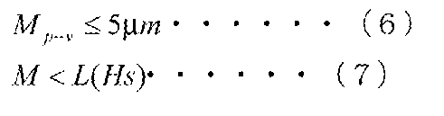
なお、式(6)において、Mp-vは、マスター担体がクッション部材に接着された状態で、マスター担体のパターン形成面の全面にわたり表面形状を測定して得られた、表面形状の高さの最大値と最小値の差(単位:μm)を表し、式(7)において、Mは、表面形状に関する上記測定の結果に基づいて、マスター担体のパターン形成面上で互いに直交するX方向およびY方向を任意に設定し、パターン形成面のそれぞれの位置においてX方向の傾きおよびY方向の傾きを求めて得られた、すべてのX方向の傾きおよびすべてのY方向の傾きの大きさのうち最大値(単位:μm/mm)を表す。
さらに、本発明に係る担体固定部材は、
ベース部材と、両面に粘着剤が付与された弾性部材から構成されるクッション部材とを備え、一方の面に転写情報に対応する凹凸パターンを有するマスター担体が接着される担体固定部材において、
クッション部材が、ベース部材に一方の面で接着されたものであり、
マスター担体と接着されるクッション部材の他方の面が、表面形状に関して上記式(1)から式(3)を満たすものであることを特徴とするものである。
ベース部材と、両面に粘着剤が付与された弾性部材から構成されるクッション部材とを備え、一方の面に転写情報に対応する凹凸パターンを有するマスター担体が接着される担体固定部材において、
クッション部材が、ベース部材に一方の面で接着されたものであり、
マスター担体と接着されるクッション部材の他方の面が、表面形状に関して上記式(1)から式(3)を満たすものであることを特徴とするものである。
そして、本発明に係る担体固定部材において、弾性部材は、表面にダイヤモンドターニング加工が施されたものであることが好ましい。
さらに、本発明に係る担体固定部材の製造方法は、
両面に粘着剤が付与された弾性部材から構成されるクッション部材の一方の面をベース部材に接着する担体固定部材の製造方法において、
一方の面に転写情報に対応する凹凸パターンを有するマスター担体と接着される前記クッション部材の他方の面が、表面形状に関して上記式(1)から式(3)を満たすように、前記クッション部材を前記ベース部材に接着することを特徴とする
そして、本発明に係る担体固定部材の製造方法において、クッションシートに対して相対的に刃を引く引切り加工を行い、クッションシートからクッション部材を切り取ることにより、クッション部材を得ることが好ましく、この場合、刃とクッションシートとの成す角度が14~22度であり、クッションシートに対する刃の相対的な移動速度が20~40cm/sである条件で、引切り加工を行うことが好ましい。
両面に粘着剤が付与された弾性部材から構成されるクッション部材の一方の面をベース部材に接着する担体固定部材の製造方法において、
一方の面に転写情報に対応する凹凸パターンを有するマスター担体と接着される前記クッション部材の他方の面が、表面形状に関して上記式(1)から式(3)を満たすように、前記クッション部材を前記ベース部材に接着することを特徴とする
そして、本発明に係る担体固定部材の製造方法において、クッションシートに対して相対的に刃を引く引切り加工を行い、クッションシートからクッション部材を切り取ることにより、クッション部材を得ることが好ましく、この場合、刃とクッションシートとの成す角度が14~22度であり、クッションシートに対する刃の相対的な移動速度が20~40cm/sである条件で、引切り加工を行うことが好ましい。
本発明に係るマスターアッセンブリの製造方法は、凹凸パターンとスレーブ媒体とを密着させて磁気転写を行うマスターアッセンブリの製造において、特に、ベース部材と、ベース部材に一方の面で接着されたクッション部材であって、マスター担体と接着される他方の面が表面形状に関して上記式(1)から式(3)を満たすクッション部材とを用意し、所定の厚さを有するマスター担体をクッション部材の上記他方の面に接着させるから、マスター担体が担体固定部材に接着された時の平坦性を向上させ、かつ磁気転写の際マスター担体とスレーブ媒体とを密着させた時の横伸びを抑制することができる。したがって、マスターアッセンブリにおいて、マスター担体とスレーブ媒体との密着性を確保しつつ、磁気転写された記録媒体のRROを60nm未満にまで低減することが可能となる。
さらに、本発明に係るマスターアッセンブリは、凹凸パターンとスレーブ媒体とを密着させて磁気転写を行うマスターアッセンブリにおいて、マスター担体の凹凸パターンのパターン形成面が、クッション部材に接着された状態において、表面形状に関し上記式(6)および式(7)を満たすものであるから、マスター担体が担体固定部材に接着された時の平坦性を向上させ、かつ磁気転写の際マスター担体とスレーブ媒体とを密着させた時の横伸びを抑制することができる。したがって、マスターアッセンブリにおいて、マスター担体とスレーブ媒体との密着性を確保しつつ、磁気転写された記録媒体のRROを60nm未満にまで低減することが可能となる。
さらに、本発明に係る担体固定部材およびその製造方法は、一方の面に転写情報に対応する凹凸パターンを有するマスター担体が接着される担体固定部材において、クッション部材が、ベース部材に一方の面で接着されたものであり、マスター担体と接着されるクッション部材の他方の面が、表面形状に関して上記式(1)から式(3)を満たすものであるから、マスター担体が担体固定部材に接着された時の平坦性を向上させ、かつ磁気転写の際マスター担体とスレーブ媒体とを密着させた時の横伸びを抑制することができる。したがって、担体固定部材およびその製造方法を利用して製造されたマスターアッセンブリにおいて、マスター担体とスレーブ媒体との密着性を確保しつつ、磁気転写された記録媒体のRROを60nm未満にまで低減することが可能となる。
以下、本発明の実施形態について図面を用いて説明するが、本発明はこれに限られるものではない。なお、視認しやすくするため、図面中の各構成要素の縮尺等は実際のものとは適宜異ならせてある。
本実施形態のマスターアッセンブリ1の製造方法は、所定の厚さを有するマスター担体を用意し、ベース部材と、ベース部材に一方の面で接着されたクッション部材であって、マスター担体と接着される他方の面が表面形状に関して上記式(1)から式(3)を満たすクッション部材とを用意し、マスター担体を、このクッション部材に接着させるものである。
また、上記方法により製造されたマスターアッセンブリ1は、ベース部材と、両面に粘着剤が付与された弾性部材から構成されるクッション部材と、一方の面に転写情報に対応する凹凸パターンを有するマスター担体とを備え、マスター担体がクッション部材を介してベース部材に固定された状態で、凹凸パターンとスレーブ媒体とを密着させて磁気転写を行うマスターアッセンブリにおいて、マスター担体の凹凸パターンのパターン形成面が、クッション部材に接着された状態において、表面形状に関し上記式(6)および式(7)を満たすものである。
なお、本発明の担体固定部材は、上記ベース部材と、ベース部材に一方の面で接着されたクッション部材とから構成される。
本願発明のマスターアッセンブリ1の製造方法は、磁気転写された記録媒体のRROをより低減することができる観点から、上記式2が上記式2aであることが好ましい。
図1は、本実施形態により製造されたマスターアッセンブリを示す概略断面図である。上記のマスターアッセンブリ1の製造方法を実施することにより、例えば図1に示すような、ホルダーユニット型のマスターアッセンブリ1を製造することができる。図1には、便宜上スレーブ媒体40も示されている。
より詳細には、本実施形態のホルダーユニット型マスターアッセンブリ1は、マスターアッセンブリ下部10と上部11とから構成される。マスターアッセンブリ下部10は、ベース部材2(ホルダープレート)とOリング5とクッション部材27aとからなる第1の担体固定部材、およびマスター担体30aにより構成される。一方、マスターアッセンブリ上部11は、ベース部材3(ホルダープレート)とクッション部材27bとからなる第2の担体固定部材、およびマスター担体30bにより構成される。上記のように、本実施形態のマスターアッセンブリ1は、2つのベース部材2および3と、それぞれのベース部材と一方の面でそれぞれ接着された2つのクッション部材27aおよび27bと、それぞれのクッション部材の他方の面にそれぞれ接着された2つのマスター担体30aおよび30bとを備え、それぞれのマスター担体30aおよび30bの凹凸パターンによってスレーブ媒体40を挟むように密着させて磁気転写を行うための構造体である。
(担体固定部材)
第1および第2の担体固定部材は、それぞれ本願発明の担体固定部材であり、ベース部材2および3、並びにクッション部材27aおよび27bを備え、クッション部材27aおよび27bがベース部材2および3に一方の面でそれぞれ接着された状態において、そのクッション部材27aおよび27bの他方の面が、その表面形状に関し上記式(1)から式(3)を満たすものである。
第1および第2の担体固定部材は、それぞれ本願発明の担体固定部材であり、ベース部材2および3、並びにクッション部材27aおよび27bを備え、クッション部材27aおよび27bがベース部材2および3に一方の面でそれぞれ接着された状態において、そのクッション部材27aおよび27bの他方の面が、その表面形状に関し上記式(1)から式(3)を満たすものである。
(ベース部材)
ベース部材2および3は、その一方または両方が軸方向に移動可能に設けられて図示しない開閉機構によって開閉作動される。ベース部材2および3は、円盤状で、マスター担体30aおよび30bの外径より大きい円形状の平面を有し、面の中央部にシート状のクッション部材27aおよび27bがその粘着性により接着されている。マスター担体30aおよび30bは、クッション部材27aおよび27bの上に粘着などにより固定される。ベース部材2および3の中心部には、マスター担体30aおよび30b及びスレーブ媒体40の中央開口部に挿通されるセンターコア6が突設されており、これによってスレーブ媒体40は、着脱自在に保持される。ベース部材2および3の外周には、対向する方向に突出する鍔部4がそれぞれ設けられている。そして、ベース部材2および3の鍔部4にOリング5が設けられ、Oリング5によりベース部材2および3が閉じられた際に形成されるこれらの間の内部空間を密閉できる構成になっている。
ベース部材2および3は、その一方または両方が軸方向に移動可能に設けられて図示しない開閉機構によって開閉作動される。ベース部材2および3は、円盤状で、マスター担体30aおよび30bの外径より大きい円形状の平面を有し、面の中央部にシート状のクッション部材27aおよび27bがその粘着性により接着されている。マスター担体30aおよび30bは、クッション部材27aおよび27bの上に粘着などにより固定される。ベース部材2および3の中心部には、マスター担体30aおよび30b及びスレーブ媒体40の中央開口部に挿通されるセンターコア6が突設されており、これによってスレーブ媒体40は、着脱自在に保持される。ベース部材2および3の外周には、対向する方向に突出する鍔部4がそれぞれ設けられている。そして、ベース部材2および3の鍔部4にOリング5が設けられ、Oリング5によりベース部材2および3が閉じられた際に形成されるこれらの間の内部空間を密閉できる構成になっている。
ベース部材2および3は、図示しない回転機構に連係されて一体に回転駆動される。また、マスターアッセンブリ1は、ベース部材2と3の摺接によって形成される内部空間のエアを真空吸引し、内部を減圧状態として、スレーブ媒体40とマスター担体30aおよび30bとの密着性を向上させるため、図示しない真空吸引手段に吸引路7および8を介して接続されている。吸引路7および8は、例えば、鍔部4より内周側で、マスター担体30aより内周部および外周部の内部空間に開口を有するようにベース部材2に設けられている。真空吸引手段によるエアの真空吸引により、マスター担体30aおよび30bによって挟むようにスレーブ媒体40に密着させるとともに、ベース部材2および3が嵌合された際に形成される内部空間を所定の真空度に制御することができる。
ベース部材2および3の材料は、ガラス、金属等を用いることができ、特に限定されないが、良好な磁界印加を実現するために、ステンレス等の非磁性材料を用いることが好ましい。
(クッション部材)
クッション部材27aおよび27bは、弾性特性を有する弾性材料からなり、密着圧力印加時にマスター担体の弾性変形を許容し、スレーブ媒体40とマスター担体30aおよび30bとの表面形状を一致させて密着性を高め、密着力を解放した際には元の状態に復元する特性を備えている。そして、クッション部材27aおよび27bは、ベース部材2および3に一方の面でそれぞれ接着された状態において、他方の面が表面形状に関し上記式(1)から式(3)を満たすものである。このような特性を実現するために、クッション部材27aおよび27bは、例えば両面に粘着剤(21a、21b、25aおよび25b)が付与された弾性部材23aおよび23bから構成することができる。弾性部材の材質、厚み等は、その加圧力による弾性部材の加圧方向の変形量が5μm~500μmの範囲となるように設定されることが好ましい。弾性部材の弾性率(ヤング率)は、3.4MPa~42.9MPaであるものが好ましい。
クッション部材27aおよび27bは、弾性特性を有する弾性材料からなり、密着圧力印加時にマスター担体の弾性変形を許容し、スレーブ媒体40とマスター担体30aおよび30bとの表面形状を一致させて密着性を高め、密着力を解放した際には元の状態に復元する特性を備えている。そして、クッション部材27aおよび27bは、ベース部材2および3に一方の面でそれぞれ接着された状態において、他方の面が表面形状に関し上記式(1)から式(3)を満たすものである。このような特性を実現するために、クッション部材27aおよび27bは、例えば両面に粘着剤(21a、21b、25aおよび25b)が付与された弾性部材23aおよび23bから構成することができる。弾性部材の材質、厚み等は、その加圧力による弾性部材の加圧方向の変形量が5μm~500μmの範囲となるように設定されることが好ましい。弾性部材の弾性率(ヤング率)は、3.4MPa~42.9MPaであるものが好ましい。
弾性部材のゴム硬度が高いと磁気転写時のマスター担体の横伸びが抑制される分、マスター担体の表面形状の高さに関するMが大きくても、ある一定のRROに収めることができる。反対に弾性部材のゴム硬度が低いと磁気転写時のマスター担体の横伸びが大きくなるため、マスター担体の表面形状の高さに関するMは小さくならないと、ある一定のRROに収めることができない。この観点で、本発明に用いられる弾性部材のゴム硬度は高いほど良く、ゴム硬度60~95が好ましく、さらに好ましくはゴム硬度70~80である。ゴム硬度60以下では厚みの均一性の高い弾性体が得られにくいため好ましくなく、ゴム硬度95以上では、磁気転写時のマスター担体とスレーブ媒体の密着性が低下し、転写信号の欠落を生じるため好ましくない。なお、上記ゴム硬度は、ショアA型硬度計によって測定した値である。具体的には、弾性部材の材料は、ウレタンゴムやニトリルブタジエンゴム、フッ素ゴム等が好ましい。また、弾性部材は、弾性部材の表面にダイヤモンドターニング加工が施されているものであることが好ましい。
本明細書において、上記式(1)および(2)におけるクッション部材の表面形状の高さは、ベース部材に接着された状態のクッション部材の表面を、レーザ走査方式表面形状測定装置(株式会社キーエンス製)によって測定して、求めた値である。そして、上記式(5)および(6)における、マスター担体がクッション部材に接着された状態でのマスター担体の表面形状の高さについても同様である。また、マスター担体の厚さdは、マスター担体30aおよび30bの凹凸パターンが形成されたパターン形成面(凹凸パターンの凸部の上面に沿った面)から反対側の面までの長さである。
クッション部材27aおよび27bは、所定の大きさのクッションシートから所望の大きさおよび形状のクッション部材を切り取ることにより形成することができる。また、クッション部材27aおよび27bを弾性部材および粘着材を用いて積層する場合には、まず弾性シートに粘着材を設けてその後に弾性シートから所望の大きさおよび形状のクッション部材を切り取ることが好ましい。クッションシートの作製方法については、特許文献1に詳細に記載されている。クッションシートから所望の大きさおよび形状のクッション部材を切り取る方法としては、打抜き加工以外に、レーザ加工、ウォータージェット加工、引切り加工を適用しても良い。特にクッション部材の端部の形状が盛り上がることを防止するため、引切り加工を用いることが好ましい。
弾性体と粘着材を組み合わせて形成されるクッション部材が、ベース部材上に固定された際、ベース部材の表面を基準にベース部材に固定されたクッション部材の表面形状の高さの測定をクッション部材の表面全面にわたって行い、クッション部材の表面形状の高さの最大値と最小値の差をCp-vとしたとき、Cp-vは5um以下であることが好ましい。5um以上であると、マスター担体とスレーブ媒体との密着性が低下するためである。
(クッション部材の切取り加工)
打抜き加工とは、加工対象部材表面に対し垂直に刃先が侵入することで、加工対象部材をせん断加工する加工方法のことである。打抜き加工において、複数の部材が積層して成る加工対象部材である場合、各部材を横断するように刃先が移動する。本発明で用いる弾性部材とその両面の粘着材とから成るクッション部材を加工する際は、まず上層の粘着材層に刃先が侵入し、次いで弾性部材に刃先が侵入し、次いで下層の粘着材層に刃先が侵入する。各部材に刃先が侵入し、各部材の変形を伴いつつ、部材が変形の限界を迎えるとせん断される。せん断が終了した後は、刃先が侵入方向の反対側に移動し刃が取り出されて加工が終了となる。打抜き加工は、加工手段としては短時間での加工が可能であり、生産性が良い。
打抜き加工とは、加工対象部材表面に対し垂直に刃先が侵入することで、加工対象部材をせん断加工する加工方法のことである。打抜き加工において、複数の部材が積層して成る加工対象部材である場合、各部材を横断するように刃先が移動する。本発明で用いる弾性部材とその両面の粘着材とから成るクッション部材を加工する際は、まず上層の粘着材層に刃先が侵入し、次いで弾性部材に刃先が侵入し、次いで下層の粘着材層に刃先が侵入する。各部材に刃先が侵入し、各部材の変形を伴いつつ、部材が変形の限界を迎えるとせん断される。せん断が終了した後は、刃先が侵入方向の反対側に移動し刃が取り出されて加工が終了となる。打抜き加工は、加工手段としては短時間での加工が可能であり、生産性が良い。
ところで、本発明に用いるクッション部材の加工において、マスター担体がドーナツ状であるため、それに合わせて内径と外径を円形加工する必要がある。理想的には加工した後に、クッション部材の厚みが均一であることが望まれる。しかし打抜き加工の場合には、加工端部においてクッション部材の厚みが局所的に変わる事が本発明者により見出された。これは、刃先が上層の粘着材層に侵入する際、粘着材の一部が刃先の側面に付着し、刃先の移動に伴って粘着材が引き伸ばされることが原因と分かった。その結果、加工端部におけるクッション部材の厚みの増加をもたらしていた。この問題に対し、刃先角度、粘着材の付着を防止するためのコーティング、刃先の移動速度、クッション部材表面の固定、打抜き加工時のクッション部材の温度等を適宜変えて検討した。しかし、いずれの対策も粘着材の刃先への付着を完全にゼロにすることはできず、加工端部におけるクッション部材の厚みの増加を抑制することが難しかった。
物理的な接触を伴わないレーザ加工での加工も検討したが、加工端部における熱変質により打抜き加工のときよりもより加工端部における厚みの増加が生じてしまった。さらに、粘着材層の付着を防止する観点でウォータージェット切断加工も検討したが、水圧により粘着材層が引き伸ばされる現象は低減されず、打抜き加工と同様に加工端部における厚みの増加が生じてしまった。さらに、ウォータージェット切断加工では、加工寸法精度が悪く、所望の内径および外径を得ることができなかった。
以上のように、内径および外径の加工後の加工端部における厚み増加が伴わない、加工方法を見出すことは非常に困難であった。この問題に対し、発明者が鋭意検討を行った結果、引切り加工を適用することで、上記のような問題を解決できることが分かった。
引切り加工とは、加工対象部材の表面に対し垂直に刃先を侵入させた後、侵入方向に対し垂直方向に刃先を加工対象部材に対して相対移動することにより、加工対象部材を切断する加工方法のことである。引切り加工の場合、複数の部材が積層して成る加工対象部材であっても、切断加工中において刃先の各部位に対し必ず同一種の部材が当ることになり、切断加工中の各部材が切断されるときの条件は各部材ごとに同一条件を保つことができることが特徴である。ただし、一方で生産性の観点において、引切り加工は打抜き加工ほどの短時間での加工を実施するのは難しい。これは、打抜き加工が打抜き刃による内周および外周の一斉加工に対し、引切り加工は刃先が内周或いは外周を一周することで加工を行うことによる。上記のような特性を考慮し、加工方法は適宜選択することが好ましい。
本発明で用いるクッション部材の加工において、引切り加工を適用することで、加工端部におけるクッション部材の厚み方向の変形を最小に収める事ができると分かった。打抜き加工またはその他の加工で見られた粘着材層の引き伸ばしは、この引切り加工ではクッション部材の厚み方向には発生せず、粘着材層と平行な方向に発生する。すなわち、引切り加工では加工端部におけるクッション部材の厚みの増加が生じない。
本発明で用いるクッション部材の加工においては、円形加工のため、刃先がある程度細い必要がある。そのため、刃先の機械的剛性が得られにくく、引切り加工時に刃先が揺れやすくなり、所望の加工寸法精度が得られない場合があることが判明した。この点に関し、加工対象部材に対する刃の角度および刃先の相対的な移動速度を調整することで、所望の加工寸法精度を得ることができるとわかった。より具体的には、本発明で用いるクッション部材の加工においては、刃とクッション部材の成す角が14~22度の間であり、かつ、加工時の刃とクッション部材との相対移動速度が20~40cm/secであることが好ましい。なお、本発明で用いるクッション部材の引切り加工には、株式会社フタバ製の替刃メスNo.19(特殊鋼製)を用いた。図2の通りに部材と刃の成す角を定義する。
以上を踏まえ、本実施形態におけるクッション部材の製造方法は、例えば図2に示すように、ベース部材とマスター担体とを接着固定するためのクッション部材の製造方法において、クッションシート45に対して相対的に刃48を引く引切り加工を行うことにより、クッションシート45からクッション部材を切り取るものである。製造が容易であると言う観点から、刃48を固定し、クッションシート45を刃48に接触させたままシート面に垂直な軸を中心として一方向に回転させることにより、相対的な移動を実現することが好ましい。
(マスター担体)
マスター担体は、表面に所望の凹凸パターン形状を有する構造体であり、その凹凸パターンの形状に応じた磁化パターンをスレーブ媒体に転写するための磁気転写用の原盤である。マスター担体は例えば、表面が平滑な石英ガラス等からなる円形の基板上に、フォトレジストをスピンコーター等により塗布し、プリベーク後に、記録する信号に対応して変調したレーザ光(或いは電子ビーム)をフォトレジストに照射して、フォトレジストの略全面に所定のパターンを露光し、露光された部分のフォトレジストを除去し、残ったフォトレジストをマスクとしてエッチングして、当該基板の表面上に凹凸パターンを形成し、この凹凸パターンのある表面上にNiを電鋳して、この電鋳部分を剥離することにより、製造することができる。本願発明のマスターアッセンブリ1において、マスター担体の厚みは、200nm以上600nm未満であることが好ましい。下限については、200nmよりもマスター担体の厚みが薄いとマスター担体の十分な剛性が確保できず、マスター担体の全体的な形状が下地のクッション部材のわずかな歪みにも影響されてしまい、マスター担体の全体的な平坦性が低下してしまうためである。上限については、マスター担体の厚みが600nm以上であるとマスター担体の剛性がありすぎて、マスター担体がスレーブ媒体に密着されたとき、マスター担体の全体的な形状が変形しながらスレーブ媒体の表面形状に沿って密着することができなくなり、マスター担体およびスレーブ媒体の密着性が低下してしまうためである。
マスター担体は、表面に所望の凹凸パターン形状を有する構造体であり、その凹凸パターンの形状に応じた磁化パターンをスレーブ媒体に転写するための磁気転写用の原盤である。マスター担体は例えば、表面が平滑な石英ガラス等からなる円形の基板上に、フォトレジストをスピンコーター等により塗布し、プリベーク後に、記録する信号に対応して変調したレーザ光(或いは電子ビーム)をフォトレジストに照射して、フォトレジストの略全面に所定のパターンを露光し、露光された部分のフォトレジストを除去し、残ったフォトレジストをマスクとしてエッチングして、当該基板の表面上に凹凸パターンを形成し、この凹凸パターンのある表面上にNiを電鋳して、この電鋳部分を剥離することにより、製造することができる。本願発明のマスターアッセンブリ1において、マスター担体の厚みは、200nm以上600nm未満であることが好ましい。下限については、200nmよりもマスター担体の厚みが薄いとマスター担体の十分な剛性が確保できず、マスター担体の全体的な形状が下地のクッション部材のわずかな歪みにも影響されてしまい、マスター担体の全体的な平坦性が低下してしまうためである。上限については、マスター担体の厚みが600nm以上であるとマスター担体の剛性がありすぎて、マスター担体がスレーブ媒体に密着されたとき、マスター担体の全体的な形状が変形しながらスレーブ媒体の表面形状に沿って密着することができなくなり、マスター担体およびスレーブ媒体の密着性が低下してしまうためである。
以下、本願発明のマスターアッセンブリ1の製造方法の作用を説明する。
RROとは、磁気ヘッドを位置決めする際に発生する誤差の回転同期成分のことであり、言い換えれば、媒体の回転中心を中心とする真円に対し、媒体上に記録されたあるトラックが回転に際し当該真円上から外れる位置差のことを言う。例えばHDDまたはスピンスタンド評価において、サーボ信号に含まれるシリンダ番号とバースト信号の復調を媒体一周分について行うことでRROが測定される。
発明者による検討により、マスターアッセンブリ上に貼り合わされたマスター担体の表面形状、および、磁気転写時にマスター担体および磁気媒体が互いに密着した時のマスター担体の横伸びがRROの大小に寄与することを見出した。マスターアッセンブリ上に貼り合わされたマスター担体は、例えばベース部材表面を高さの基準としてある特定の表面形状の高さを有する。このマスター担体の高さ分布は、マスター担体自身の厚みむら、クッション部材の貼合せ形状、ベース部材表面の表面形状の影響で決定される。磁気転写を行う際、マスターアッセンブリ上に貼り合わされたマスター担体は、磁気転写用のスレーブ媒体と密着させられる。このとき、マスター担体とスレーブ媒体との全面の密着が行われるよう適度な圧力が印加され、マスター担体はスレーブ媒体の転写面に沿うように横に伸びながら形状が変形する(横伸び)。すなわちマスター担体は、マスターアッセンブリ上に貼り合わされた時に成している初期の形状から、磁気転写時の密着時にはその初期形状から横伸びしている。この横伸びの際、マスター担体上に形成された凹凸パターンもマスター担体に追従し横伸びする。このようなマスター担体とスレーブ媒体との密着に起因して、本来変形なしに転写されるべき凹凸パターンが、マスター担体の横伸びに伴って横伸びした状態でスレーブ媒体に転写され、この横伸びがRROとして磁気転写信号に反映されると考えられる。
この横伸びは、マスター担体自身のポアソン比、および、クッション部材のうちの弾性部材が横伸びする際にマスター担体を引っ張る力に起因して発生する。このマスター担体の横伸びは、必ずしも等方的な伸びにならず、一般的に伸びやすい方向、伸びにくい方向を有するため、マスター担体の横伸びはRROの増大に影響を与える。マスター担体の横伸びの上記2つの原因のうち、支配的な要因は弾性部材の横伸びである。したがって、弾性部材の横伸びが小さければマスター担体の横伸びも小さくなり、その結果、RROの増大を抑制することができる。
発明者が鋭意検討を行った結果、マスター担体の厚み、マスター担体のヤング率、クッション部材に用いられる弾性体のヤング率とゴム硬度、マスターアッセンブリ上に固定された時のクッション部材の表面形状が、マスターアッセンブリ上に貼り合わされたマスター担体の表面形状と磁気転写時のマスター担体の横伸びとを支配しており、その結果RROが増大してしまうことを見出した。
マスターアッセンブリ上に貼り合わされたマスター担体の表面形状の高さは、クッション部材がベース部材上に固定された時に有する表面形状の高さと、マスター担体の曲げ剛性と、クッション部材のヤング率との関係で決定される。クッション部材をベース部材上に貼り合わせた際、ベース部材表面の表面形状の影響、クッション部材の厚み分布、クッション部材の加工端部形状の影響によりクッション部材の表面形状の高さが決定される。一般的にクッション部材の表面形状の高さを完全に均一にすることは難しく、ある表面形状の高さの分布を有する。
また、ベース部材上に固定されたクッション部材にマスター担体を貼り合わせることでマスターアッセンブリを得るが、マスターアッセンブリ上に貼り合わされたマスター担体の表面形状の高さはクッション部材の表面形状の高さの影響を受ける。このとき、クッション部材がマスター担体をクッション部材の形状にならわせようとして引っ張る力と、マスター担体が曲げに堪える力の釣り合いにより、マスター担体の表面形状の高さが決定される。すなわち、クッション部材がベース部材上に固定された時に有する表面形状の高さと、マスター担体の曲げ剛性とクッション部材のヤング率の関係によりマスターアッセンブリ上に貼り合わされたマスター担体の表面形状の高さが決定される。
より具体的には、クッション部材が一方の面でベース部材に接着された状態で、クッション部材の他方の面の全面にわたり表面形状を測定し、表面形状に関する上記測定の結果に基づいて、クッション部材の上記他方の面上で互いに直交するX方向およびY方向を任意に設定し、上記他方の面のそれぞれの位置においてX方向の傾きおよびY方向の傾きを求めて得られた、すべてのX方向の傾きおよびすべてのY方向の傾きの大きさのうち最大値をC(単位:μm/mm)、マスター担体の厚みをd(um)、マスター担体のヤング率をEm(GPa)、弾性体のヤング率をEc(GPa)としたとき、マスターアッセンブリ上に固定されたマスター担体の表面形状の高さの傾きの大きさの最大値Mは、下記式(8)で得られることが分かった。

ここで、K(d)は、下記式(9)により得られるマスター担体の曲げ剛性に相当する量であり、マスター担体のヤング率Emとマスター担体の厚さdの3乗に比例する量である。

マスター担体の厚さdが大きいほどMが小さくなり、結果としてRROを小さくすることができるが、マスター担体が厚くなると磁気転写時にマスター担体とスレーブ媒体との密着性が低下し、転写信号の欠落をもたらす。この観点から、マスター担体の曲げ剛性に相当する量K(d)は0.04GPa以下が好ましい。
上記式(8)は、クッション部材がマスター担体をクッション部材の形状にならわせようとして引っ張る力と、マスター担体が曲げに堪える力の釣り合いの関係から導き出すことが出来る。クッション部材が初期の変形状態を有し、クッション部材上にマスター担体を貼り合わせる際、クッション部材はマスター担体と接着することでマスター担体の形状にならおうと変形を始める。クッション部材がマスター担体形状に近づくように変形をすると、クッション部材はヤング率Ecをバネ定数とした復元力を発し、マスター担体を引っ張る力が生まれる。この状況の中、マスター担体はクッション部材からの引力によりクッション部材の形状にならおうとする。しかし、マスター担体は自身に曲げ剛性を有するため、クッション部材からの引力に対して抗力を発する。このクッション部材からの引力とマスター担体の抗力のつりあう位置でマスター担体およびクッション部材の最終的な変形状態が決定される。この力の釣り合いを表す方程式を整理すると上記の関係式が導き出された。この際、クッション部材は弾性体と粘着材からなる複合部材であるが、粘着材のヤング率が弾性体に比べて無視できるほど低く、また、粘着材の厚みが十分に薄いことから力の釣り合いに関し寄与が小さいことから、粘着材の寄与を無視した。
上記式(9)中の係数9.0×10⁻⁴は実験的に求められた定数である。具体的には、係数9.0×10⁻⁴は、断面2次モーメントとして、マスター担体の形状とマスター担体の拘束条件により決定される。本発明におけるマスター担体はクッション部材に貼り合わされた状態でマスターアッセンブリを成す。この拘束条件の元、表1のように、クッション部材の表面形状の高さに関する上記Cがほぼ等しくかつ厚みが異なるクッション部材を用いて、マスター担体を貼合せた際のマスター担体の表面形状の高さに関する上記Mの関係を調べ、図3に示すグラフ上のプロットを最小二乗法で近似し、その傾きから比例係数が9.0×10⁻⁴(mm-3)になることを実験で求めた。

前述したようにRROは、マスター担体の表面形状の高さに関するMと磁気転写時のマスター担体の横伸びによって決定されることを説明した。RROを一定の量以下に制御することを目的とした場合、マスター担体の横伸びの程度により、マスター担体の表面形状の高さに関するMの許容量が決定される。発明者による実験的な検証により、マスター担体の表面形状の高さに関するMの許容量L(Hs)と弾性部材のゴム硬度Hsとの間に以下の関係式が成り立つことを見出した。

上記式(10)は、マスター担体の表面形状の高さに関するMの許容量L(Hs)とHsの関係を調べることにより実験的に求めた。具体的には、表2に示すように、同一の厚さを有するマスター担体をゴム硬度の異なるクッション部材に貼合せ、磁気転写を行った後に、RROが許容量である60nmになる時の指標Mを実験で確認した。実験で得られた結果を図4に示すようにグラフ上にプロットし、これに関して最小二乗法で近似曲線を作成した。その結果、本発明の適用の範囲ではL(Hs)はHsに対し上記式(10)のような関係を満たすことが分かった。

以上により、本発明に係るマスターアッセンブリの製造方法は、凹凸パターンとスレーブ媒体とを密着させて磁気転写を行うマスターアッセンブリの製造において、特に、ベース部材と、ベース部材に一方の面で接着されたクッション部材であって、マスター担体と接着される他方の面が表面形状に関して上記式(1)から式(3)を満たすクッション部材とを用意し、所定の厚さを有するマスター担体をクッション部材の上記他方の面に接着させるから、マスター担体が担体固定部材に接着された時の平坦性を向上させ、かつ磁気転写の際マスター担体とスレーブ媒体とを密着させた時の横伸びを抑制することができる。したがって、マスターアッセンブリにおいて、マスター担体とスレーブ媒体との密着性を確保しつつ、磁気転写された記録媒体のRROを60nm未満にまで低減することが可能となる。
さらに、本発明に係るマスターアッセンブリは、凹凸パターンとスレーブ媒体とを密着させて磁気転写を行うマスターアッセンブリにおいて、マスター担体の凹凸パターンのパターン形成面が、クッション部材に接着された状態において、表面形状に関し上記式(6)および式(7)を満たすものであるから、マスター担体が担体固定部材に接着された時の平坦性を向上させ、かつ磁気転写の際マスター担体とスレーブ媒体とを密着させた時の横伸びを抑制することができる。したがって、マスターアッセンブリにおいて、マスター担体とスレーブ媒体との密着性を確保しつつ、磁気転写された記録媒体のRROを60nm未満にまで低減することが可能となる。
さらに、本発明に係る担体固定部材およびその製造方法は、一方の面に転写情報に対応する凹凸パターンを有するマスター担体が接着される担体固定部材において、クッション部材が、ベース部材に一方の面で接着されたものであり、マスター担体と接着されるクッション部材の他方の面が、表面形状に関して上記式(1)から式(3)を満たすものであるから、マスター担体が担体固定部材に接着された時の平坦性を向上させ、かつ磁気転写の際マスター担体とスレーブ媒体とを密着させた時の横伸びを抑制することができる。したがって、担体固定部材およびその製造方法を利用して製造されたマスターアッセンブリにおいて、マスター担体とスレーブ媒体との密着性を確保しつつ、磁気転写された記録媒体のRROを60nm未満にまで低減することが可能となる。
本発明に係るマスターアッセンブリの製造方法の実施例を以下に示す。
<マスターアッセンブリの製造>
表3および表4に示す、マスターアッセンブリの各製造条件(マスター担体の材質、マスター担体の厚さ、マスター担体のヤング率、クッション部材の切取り加工方法、クッション部材のヤング率、弾性部材のゴム硬度)に基づいて、マスターアッセンブリの製造方法の実施例1-1から1-47を実施した。なお、表中の「DT加工」はダイヤモンドターニング加工を意味する。これらの実施例により製造されたマスターアッセンブリを使用して、スレーブ媒体との密着性および磁気転写された記録媒体のRROを評価した。そして、2つの評価項目において、密着性が良好でありかつRROが60nm未満である場合に本発明の課題が解決できたとして総合的な評価を行った。
<マスターアッセンブリの製造>
表3および表4に示す、マスターアッセンブリの各製造条件(マスター担体の材質、マスター担体の厚さ、マスター担体のヤング率、クッション部材の切取り加工方法、クッション部材のヤング率、弾性部材のゴム硬度)に基づいて、マスターアッセンブリの製造方法の実施例1-1から1-47を実施した。なお、表中の「DT加工」はダイヤモンドターニング加工を意味する。これらの実施例により製造されたマスターアッセンブリを使用して、スレーブ媒体との密着性および磁気転写された記録媒体のRROを評価した。そして、2つの評価項目において、密着性が良好でありかつRROが60nm未満である場合に本発明の課題が解決できたとして総合的な評価を行った。
表3および表4より、本発明のマスターアッセンブリの製造方法を用いることにより、これにより製造されたマスターアッセンブリを使用して、マスター担体とスレーブ媒体との密着性を確保しつつ、磁気転写された記録媒体のRROを60nm未満にまで低減できることが立証された。
一方、表5は、実施例1-2において、クッション部材の切取り加工方法として打抜き加工に換えて引切り加工を採用した場合の実施例の結果を示す表である。実施例2-1から2-9では、それぞれ引切り加工における移動速度や刃角度を変えて実施した。
表5より、クッション部材の切取り加工方法として打抜き加工よりも引切り加工を採用した方が、マスター担体とスレーブ媒体との密着性を確保しつつ、磁気転写された記録媒体のRROをより低減できることが立証された。


Claims (11)
- ベース部材と、両面に粘着剤が付与された弾性部材から構成されるクッション部材と、一方の面に転写情報に対応する凹凸パターンを有するマスター担体とを備え、該マスター担体が前記クッション部材を介して前記ベース部材に固定された状態で、前記凹凸パターンとスレーブ媒体とを密着させて磁気転写を行うマスターアッセンブリの製造方法において、
前記ベース部材と、該ベース部材に一方の面で接着された前記クッション部材であって、前記マスター担体と接着される他方の面が表面形状に関して下記式(1)から式(3)を満たす前記クッション部材とを用意し、
所定の厚さを有する前記マスター担体を前記クッション部材の前記他方の面に接着させることを特徴とするマスターアッセンブリの製造方法。

Cp-vは、前記クッション部材が前記一方の面で前記ベース部材に接着された状態で、前記クッション部材の前記他方の面の全面にわたり表面形状を測定して得られた、表面形状の高さの最大値と最小値の差(単位:μm)を表し、
式(2)において、
Cは、表面形状に関する前記測定の結果に基づいて、前記クッション部材の前記他方の面上で互いに直交するX方向およびY方向を任意に設定し、前記他方の面のそれぞれの位置においてX方向の傾きおよびY方向の傾きを求めて得られた、すべてのX方向の傾きおよびすべてのY方向の傾きの大きさのうち最大値(単位:μm/mm)を表し、
Ecは、前記弾性部材のヤング率(単位:GPa)を表し、
K(d)は、前記マスター担体の曲げ剛性に相当する量(単位:GPa)を表し、下記式(4)で得られる値であり、
L(Hs)は、式(1)における上限値を表し、下記式(5)で得られる値である。

Emは、前記マスター担体のヤング率(単位:GPa)を表し、
dは、前記マスター担体の厚さ(単位:mm)を表し、
式(5)において、
Hsは、前記弾性部材のゴム硬度を表す。) - 前記式(2)が、下記式(2a)であることを特徴とする請求項1に記載のマスターアッセンブリの製造方法。

- クッションシートに対して相対的に刃を引く引切り加工を行い、前記クッションシートから前記クッション部材を切り取ることにより、前記クッション部材を得ることを特徴とする請求項1または2に記載のマスターアッセンブリの製造方法。
- 前記刃と前記クッションシートとの成す角度が14~22度であり、前記クッションシートに対する前記刃の相対的な移動速度が20~40cm/sである条件で、前記引切り加工を行うことを特徴とする請求項3に記載のマスターアッセンブリの製造方法。
- 前記弾性部材が、表面にダイヤモンドターニング加工が施されているものであることを特徴とする請求項1から4いずれかに記載のマスターアッセンブリの製造方法。
- ベース部材と、両面に粘着剤が付与された弾性部材から構成されるクッション部材と、一方の面に転写情報に対応する凹凸パターンを有するマスター担体とを備え、該マスター担体が前記クッション部材を介して前記ベース部材に固定された状態で、前記凹凸パターンとスレーブ媒体とを密着させて磁気転写を行うマスターアッセンブリにおいて、
前記マスター担体の前記凹凸パターンのパターン形成面が、前記マスター担体が前記クッション部材に接着された状態において、表面形状に関し下記式(6)および式(7)を満たすものであることを特徴とするマスターアッセンブリ。
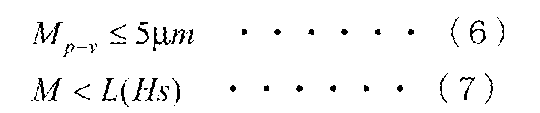
Mp-vは、前記マスター担体が前記クッション部材に接着された状態で、前記マスター担体の前記パターン形成面の全面にわたり表面形状を測定して得られた、表面形状の高さの最大値と最小値の差(単位:μm)を表し、
式(7)において、
Mは、表面形状に関する前記測定の結果に基づいて、前記マスター担体の前記パターン形成面上で互いに直交するX方向およびY方向を任意に設定し、前記パターン形成面のそれぞれの位置においてX方向の傾きおよびY方向の傾きを求めて得られた、すべてのX方向の傾きおよびすべてのY方向の傾きの大きさのうち最大値(単位:μm/mm)を表す。) - ベース部材と、両面に粘着剤が付与された弾性部材から構成されるクッション部材とを備え、一方の面に転写情報に対応する凹凸パターンを有するマスター担体が接着される担体固定部材において、
前記クッション部材が、前記ベース部材に一方の面で接着されたものであり、
前記マスター担体と接着される前記クッション部材の他方の面が、表面形状に関して下記式(1)から式(3)を満たすものであることを特徴とする担体固定部材。

Cp-vは、前記クッション部材が前記一方の面で前記ベース部材に接着された状態で、前記クッション部材の前記他方の面の全面にわたり表面形状を測定して得られた、表面形状の高さの最大値と最小値の差(単位:μm)を表し、
式(2)において、
Cは、表面形状に関する前記測定の結果に基づいて、前記クッション部材の前記他方の面上で互いに直交するX方向およびY方向を任意に設定し、前記他方の面のそれぞれの位置においてX方向の傾きおよびY方向の傾きを求めて得られた、すべてのX方向の傾きおよびすべてのY方向の傾きの大きさのうち最大値(単位:μm/mm)を表し、
Ecは、前記弾性部材のヤング率(単位:GPa)を表し、
K(d)は、前記マスター担体の曲げ剛性に相当する量(単位:GPa)を表し、下記式(4)で得られる値であり、
L(Hs)は、式(1)における上限値を表し、下記式(5)で得られる値である。

Emは、前記マスター担体のヤング率(単位:GPa)を表し、
dは、前記マスター担体の厚さ(単位:mm)を表し、
式(5)において、
Hsは、前記弾性部材のゴム硬度を表す。) - 前記弾性部材が、表面にダイヤモンドターニング加工が施されたものであることを特徴とする請求項7に記載の担体固定部材。
- 両面に粘着剤が付与された弾性部材から構成されるクッション部材の一方の面をベース部材に接着する担体固定部材の製造方法において、
一方の面に転写情報に対応する凹凸パターンを有するマスター担体と接着される前記クッション部材の他方の面が、表面形状に関して下記式(1)から式(3)を満たすように、前記クッション部材を前記ベース部材に接着することを特徴とする担体固定部材の製造方法。
Cp-vは、前記クッション部材が前記一方の面で前記ベース部材に接着された状態で、前記クッション部材の前記他方の面の全面にわたり表面形状を測定して得られた、表面形状の高さの最大値と最小値の差(単位:μm)を表し、
式(2)において、
Cは、表面形状に関する前記測定の結果に基づいて、前記クッション部材の前記他方の面上で互いに直交するX方向およびY方向を任意に設定し、前記他方の面のそれぞれの位置においてX方向の傾きおよびY方向の傾きを求めて得られた、すべてのX方向の傾きおよびすべてのY方向の傾きの大きさのうち最大値(単位:μm/mm)を表し、
Ecは、前記弾性部材のヤング率(単位:GPa)を表し、
K(d)は、前記マスター担体の曲げ剛性に相当する量(単位:GPa)を表し、下記式(4)で得られる値であり、
L(Hs)は、式(1)における上限値を表し、下記式(5)で得られる値である。

Emは、前記マスター担体のヤング率(単位:GPa)を表し、
dは、前記マスター担体の厚さ(単位:mm)を表し、
式(5)において、
Hsは、前記弾性部材のゴム硬度を表す。) - クッションシートに対して相対的に刃を引く引切り加工を行い、前記クッションシートから前記クッション部材を切り取ることにより、前記クッション部材を得ることを特徴とする請求項9に記載の担体固定部材の製造方法。
- 前記刃と前記クッションシートとの成す角度が14~22度であり、前記クッションシートに対する前記刃の相対的な移動速度が20~40cm/sである条件で、前記引切り加工を行うことを特徴とする請求項10に記載の担体固定部材の製造方法。
Applications Claiming Priority (2)
| Application Number | Priority Date | Filing Date | Title |
|---|---|---|---|
| JP2010215094A JP2012069227A (ja) | 2010-09-27 | 2010-09-27 | マスターアッセンブリの製造方法およびマスターアッセンブリ、並びに、担体固定部材および担体固定部材の製造方法 |
| JP2010-215094 | 2010-09-27 |
Publications (1)
| Publication Number | Publication Date |
|---|---|
| WO2012042838A1 true WO2012042838A1 (ja) | 2012-04-05 |
Family
ID=45892329
Family Applications (1)
| Application Number | Title | Priority Date | Filing Date |
|---|---|---|---|
| PCT/JP2011/005417 Ceased WO2012042838A1 (ja) | 2010-09-27 | 2011-09-27 | マスターアッセンブリの製造方法およびマスターアッセンブリ、並びに、担体固定部材および担体固定部材の製造方法 |
Country Status (2)
| Country | Link |
|---|---|
| JP (1) | JP2012069227A (ja) |
| WO (1) | WO2012042838A1 (ja) |
Citations (6)
| Publication number | Priority date | Publication date | Assignee | Title |
|---|---|---|---|---|
| JP2003099921A (ja) * | 2001-04-16 | 2003-04-04 | Fuji Photo Film Co Ltd | 磁気転写装置 |
| JP2003173525A (ja) * | 2001-06-21 | 2003-06-20 | Fuji Photo Film Co Ltd | 磁気転写装置 |
| JP2003217115A (ja) * | 2002-01-22 | 2003-07-31 | Fuji Photo Film Co Ltd | 磁気転写用磁気記録媒体 |
| JP2004103113A (ja) * | 2002-09-10 | 2004-04-02 | Fuji Photo Film Co Ltd | 磁気転写装置のホルダー |
| JP2008130204A (ja) * | 2006-11-24 | 2008-06-05 | Fujitsu Ltd | 磁気転写装置、磁気転写装置により製造された磁気ディスク媒体、及び磁気ディスク装置 |
| JP2010182364A (ja) * | 2009-02-04 | 2010-08-19 | Fuji Electric Device Technology Co Ltd | 磁気転写装置及び磁気転写方法 |
-
2010
- 2010-09-27 JP JP2010215094A patent/JP2012069227A/ja not_active Withdrawn
-
2011
- 2011-09-27 WO PCT/JP2011/005417 patent/WO2012042838A1/ja not_active Ceased
Patent Citations (6)
| Publication number | Priority date | Publication date | Assignee | Title |
|---|---|---|---|---|
| JP2003099921A (ja) * | 2001-04-16 | 2003-04-04 | Fuji Photo Film Co Ltd | 磁気転写装置 |
| JP2003173525A (ja) * | 2001-06-21 | 2003-06-20 | Fuji Photo Film Co Ltd | 磁気転写装置 |
| JP2003217115A (ja) * | 2002-01-22 | 2003-07-31 | Fuji Photo Film Co Ltd | 磁気転写用磁気記録媒体 |
| JP2004103113A (ja) * | 2002-09-10 | 2004-04-02 | Fuji Photo Film Co Ltd | 磁気転写装置のホルダー |
| JP2008130204A (ja) * | 2006-11-24 | 2008-06-05 | Fujitsu Ltd | 磁気転写装置、磁気転写装置により製造された磁気ディスク媒体、及び磁気ディスク装置 |
| JP2010182364A (ja) * | 2009-02-04 | 2010-08-19 | Fuji Electric Device Technology Co Ltd | 磁気転写装置及び磁気転写方法 |
Also Published As
| Publication number | Publication date |
|---|---|
| JP2012069227A (ja) | 2012-04-05 |
Similar Documents
| Publication | Publication Date | Title |
|---|---|---|
| US7784765B2 (en) | Mold, method for producing the same and magnetic recording medium | |
| JP2012033249A (ja) | 磁気転写用マスター基板、それを用いた磁気転写方法および磁気転写媒体 | |
| KR20030043747A (ko) | 자기전사용 마스터 담체 및 자기전사방법 | |
| US7009790B2 (en) | Magnetic transfer apparatus | |
| WO2012042838A1 (ja) | マスターアッセンブリの製造方法およびマスターアッセンブリ、並びに、担体固定部材および担体固定部材の製造方法 | |
| US6772507B2 (en) | Method of manufacturing magnetic recording medium | |
| US20060177699A1 (en) | Magnetic transfer master disk, its manufacturing method and magnetic transfer method | |
| KR20020087855A (ko) | 자기전사용 마스터담체 | |
| US7465383B2 (en) | Master information carrier for magnetic transfer and its production method | |
| JP4151078B2 (ja) | 磁気転写用マスターディスク及びその製造方法並びに磁気転写方法 | |
| JP2006221692A (ja) | 磁気転写用マスターディスク及びその製造方法並びに磁気転写方法 | |
| JP2006216204A (ja) | 磁気転写用マスターディスク及びその製造方法並びに磁気転写方法 | |
| JP5805636B2 (ja) | 磁気記録媒体 | |
| US20090147405A1 (en) | Method for manufacturing magnetic recording medium, magnetic recording medium manufactured by the same, and magnetic recording apparatus incorporating the magnetic recording medium | |
| US7577079B2 (en) | Master disk for magnetic transfer | |
| JP2003187434A (ja) | フレキシブル媒体への磁気転写方法 | |
| US7532420B2 (en) | Master disk for magnetic transfer, magnetic recording medium and magnetic recording apparatus | |
| US20060216550A1 (en) | Method of manufacturing master disk for magnetic transfer, master disk for magnetic transfer, and magnetic recording medium | |
| JP2012185881A (ja) | 磁気転写用の転写ホルダーおよびそれを備えた磁気転写装置 | |
| JP4761166B2 (ja) | 磁気転写用マスター体の製造方法 | |
| JP2011028824A (ja) | 磁気転写方法および磁気記録媒体 | |
| JP2006260662A (ja) | 磁気転写用マスターディスクの製造方法及び磁気記録媒体 | |
| JP2006260661A (ja) | 磁気転写用マスターディスクの製造方法及び磁気記録媒体 | |
| JP2005267730A (ja) | 磁気転写用マスター担体および磁気転写装置並びに磁気転写方法 | |
| JP2004265557A (ja) | 磁気転写用マスター担体およびその製造方法 |
Legal Events
| Date | Code | Title | Description |
|---|---|---|---|
| 121 | Ep: the epo has been informed by wipo that ep was designated in this application |
Ref document number: 11828404 Country of ref document: EP Kind code of ref document: A1 |
|
| NENP | Non-entry into the national phase |
Ref country code: DE |
|
| 122 | Ep: pct application non-entry in european phase |
Ref document number: 11828404 Country of ref document: EP Kind code of ref document: A1 |