WO2012039409A1 - Method for producing fiber-reinforced plastic - Google Patents
Method for producing fiber-reinforced plastic Download PDFInfo
- Publication number
- WO2012039409A1 WO2012039409A1 PCT/JP2011/071426 JP2011071426W WO2012039409A1 WO 2012039409 A1 WO2012039409 A1 WO 2012039409A1 JP 2011071426 W JP2011071426 W JP 2011071426W WO 2012039409 A1 WO2012039409 A1 WO 2012039409A1
- Authority
- WO
- WIPO (PCT)
- Prior art keywords
- resin
- laminate
- medium
- suction
- mold
- Prior art date
Links
Images

Classifications
-
- B—PERFORMING OPERATIONS; TRANSPORTING
- B29—WORKING OF PLASTICS; WORKING OF SUBSTANCES IN A PLASTIC STATE IN GENERAL
- B29C—SHAPING OR JOINING OF PLASTICS; SHAPING OF MATERIAL IN A PLASTIC STATE, NOT OTHERWISE PROVIDED FOR; AFTER-TREATMENT OF THE SHAPED PRODUCTS, e.g. REPAIRING
- B29C70/00—Shaping composites, i.e. plastics material comprising reinforcements, fillers or preformed parts, e.g. inserts
- B29C70/02—Shaping composites, i.e. plastics material comprising reinforcements, fillers or preformed parts, e.g. inserts comprising combinations of reinforcements, e.g. non-specified reinforcements, fibrous reinforcing inserts and fillers, e.g. particulate fillers, incorporated in matrix material, forming one or more layers and with or without non-reinforced or non-filled layers
- B29C70/021—Combinations of fibrous reinforcement and non-fibrous material
-
- B—PERFORMING OPERATIONS; TRANSPORTING
- B29—WORKING OF PLASTICS; WORKING OF SUBSTANCES IN A PLASTIC STATE IN GENERAL
- B29C—SHAPING OR JOINING OF PLASTICS; SHAPING OF MATERIAL IN A PLASTIC STATE, NOT OTHERWISE PROVIDED FOR; AFTER-TREATMENT OF THE SHAPED PRODUCTS, e.g. REPAIRING
- B29C43/00—Compression moulding, i.e. applying external pressure to flow the moulding material; Apparatus therefor
- B29C43/02—Compression moulding, i.e. applying external pressure to flow the moulding material; Apparatus therefor of articles of definite length, i.e. discrete articles
- B29C43/20—Making multilayered or multicoloured articles
-
- B—PERFORMING OPERATIONS; TRANSPORTING
- B29—WORKING OF PLASTICS; WORKING OF SUBSTANCES IN A PLASTIC STATE IN GENERAL
- B29C—SHAPING OR JOINING OF PLASTICS; SHAPING OF MATERIAL IN A PLASTIC STATE, NOT OTHERWISE PROVIDED FOR; AFTER-TREATMENT OF THE SHAPED PRODUCTS, e.g. REPAIRING
- B29C43/00—Compression moulding, i.e. applying external pressure to flow the moulding material; Apparatus therefor
- B29C43/32—Component parts, details or accessories; Auxiliary operations
- B29C43/34—Feeding the material to the mould or the compression means
-
- B—PERFORMING OPERATIONS; TRANSPORTING
- B29—WORKING OF PLASTICS; WORKING OF SUBSTANCES IN A PLASTIC STATE IN GENERAL
- B29C—SHAPING OR JOINING OF PLASTICS; SHAPING OF MATERIAL IN A PLASTIC STATE, NOT OTHERWISE PROVIDED FOR; AFTER-TREATMENT OF THE SHAPED PRODUCTS, e.g. REPAIRING
- B29C43/00—Compression moulding, i.e. applying external pressure to flow the moulding material; Apparatus therefor
- B29C43/02—Compression moulding, i.e. applying external pressure to flow the moulding material; Apparatus therefor of articles of definite length, i.e. discrete articles
- B29C43/10—Isostatic pressing, i.e. using non-rigid pressure-exerting members against rigid parts or dies
- B29C43/12—Isostatic pressing, i.e. using non-rigid pressure-exerting members against rigid parts or dies using bags surrounding the moulding material or using membranes contacting the moulding material
-
- B—PERFORMING OPERATIONS; TRANSPORTING
- B29—WORKING OF PLASTICS; WORKING OF SUBSTANCES IN A PLASTIC STATE IN GENERAL
- B29C—SHAPING OR JOINING OF PLASTICS; SHAPING OF MATERIAL IN A PLASTIC STATE, NOT OTHERWISE PROVIDED FOR; AFTER-TREATMENT OF THE SHAPED PRODUCTS, e.g. REPAIRING
- B29C43/00—Compression moulding, i.e. applying external pressure to flow the moulding material; Apparatus therefor
- B29C43/02—Compression moulding, i.e. applying external pressure to flow the moulding material; Apparatus therefor of articles of definite length, i.e. discrete articles
- B29C43/18—Compression moulding, i.e. applying external pressure to flow the moulding material; Apparatus therefor of articles of definite length, i.e. discrete articles incorporating preformed parts or layers, e.g. compression moulding around inserts or for coating articles
-
- B—PERFORMING OPERATIONS; TRANSPORTING
- B29—WORKING OF PLASTICS; WORKING OF SUBSTANCES IN A PLASTIC STATE IN GENERAL
- B29C—SHAPING OR JOINING OF PLASTICS; SHAPING OF MATERIAL IN A PLASTIC STATE, NOT OTHERWISE PROVIDED FOR; AFTER-TREATMENT OF THE SHAPED PRODUCTS, e.g. REPAIRING
- B29C43/00—Compression moulding, i.e. applying external pressure to flow the moulding material; Apparatus therefor
- B29C43/32—Component parts, details or accessories; Auxiliary operations
- B29C43/36—Moulds for making articles of definite length, i.e. discrete articles
- B29C43/3642—Bags, bleeder sheets or cauls for isostatic pressing
-
- B—PERFORMING OPERATIONS; TRANSPORTING
- B29—WORKING OF PLASTICS; WORKING OF SUBSTANCES IN A PLASTIC STATE IN GENERAL
- B29C—SHAPING OR JOINING OF PLASTICS; SHAPING OF MATERIAL IN A PLASTIC STATE, NOT OTHERWISE PROVIDED FOR; AFTER-TREATMENT OF THE SHAPED PRODUCTS, e.g. REPAIRING
- B29C70/00—Shaping composites, i.e. plastics material comprising reinforcements, fillers or preformed parts, e.g. inserts
- B29C70/04—Shaping composites, i.e. plastics material comprising reinforcements, fillers or preformed parts, e.g. inserts comprising reinforcements only, e.g. self-reinforcing plastics
- B29C70/06—Fibrous reinforcements only
-
- B—PERFORMING OPERATIONS; TRANSPORTING
- B29—WORKING OF PLASTICS; WORKING OF SUBSTANCES IN A PLASTIC STATE IN GENERAL
- B29C—SHAPING OR JOINING OF PLASTICS; SHAPING OF MATERIAL IN A PLASTIC STATE, NOT OTHERWISE PROVIDED FOR; AFTER-TREATMENT OF THE SHAPED PRODUCTS, e.g. REPAIRING
- B29C70/00—Shaping composites, i.e. plastics material comprising reinforcements, fillers or preformed parts, e.g. inserts
- B29C70/04—Shaping composites, i.e. plastics material comprising reinforcements, fillers or preformed parts, e.g. inserts comprising reinforcements only, e.g. self-reinforcing plastics
- B29C70/28—Shaping operations therefor
- B29C70/30—Shaping by lay-up, i.e. applying fibres, tape or broadsheet on a mould, former or core; Shaping by spray-up, i.e. spraying of fibres on a mould, former or core
- B29C70/36—Shaping by lay-up, i.e. applying fibres, tape or broadsheet on a mould, former or core; Shaping by spray-up, i.e. spraying of fibres on a mould, former or core and impregnating by casting, e.g. vacuum casting
-
- B—PERFORMING OPERATIONS; TRANSPORTING
- B29—WORKING OF PLASTICS; WORKING OF SUBSTANCES IN A PLASTIC STATE IN GENERAL
- B29C—SHAPING OR JOINING OF PLASTICS; SHAPING OF MATERIAL IN A PLASTIC STATE, NOT OTHERWISE PROVIDED FOR; AFTER-TREATMENT OF THE SHAPED PRODUCTS, e.g. REPAIRING
- B29C70/00—Shaping composites, i.e. plastics material comprising reinforcements, fillers or preformed parts, e.g. inserts
- B29C70/04—Shaping composites, i.e. plastics material comprising reinforcements, fillers or preformed parts, e.g. inserts comprising reinforcements only, e.g. self-reinforcing plastics
- B29C70/28—Shaping operations therefor
- B29C70/40—Shaping or impregnating by compression not applied
- B29C70/42—Shaping or impregnating by compression not applied for producing articles of definite length, i.e. discrete articles
- B29C70/44—Shaping or impregnating by compression not applied for producing articles of definite length, i.e. discrete articles using isostatic pressure, e.g. pressure difference-moulding, vacuum bag-moulding, autoclave-moulding or expanding rubber-moulding
- B29C70/443—Shaping or impregnating by compression not applied for producing articles of definite length, i.e. discrete articles using isostatic pressure, e.g. pressure difference-moulding, vacuum bag-moulding, autoclave-moulding or expanding rubber-moulding and impregnating by vacuum or injection
-
- B—PERFORMING OPERATIONS; TRANSPORTING
- B29—WORKING OF PLASTICS; WORKING OF SUBSTANCES IN A PLASTIC STATE IN GENERAL
- B29C—SHAPING OR JOINING OF PLASTICS; SHAPING OF MATERIAL IN A PLASTIC STATE, NOT OTHERWISE PROVIDED FOR; AFTER-TREATMENT OF THE SHAPED PRODUCTS, e.g. REPAIRING
- B29C70/00—Shaping composites, i.e. plastics material comprising reinforcements, fillers or preformed parts, e.g. inserts
- B29C70/04—Shaping composites, i.e. plastics material comprising reinforcements, fillers or preformed parts, e.g. inserts comprising reinforcements only, e.g. self-reinforcing plastics
- B29C70/28—Shaping operations therefor
- B29C70/54—Component parts, details or accessories; Auxiliary operations, e.g. feeding or storage of prepregs or SMC after impregnation or during ageing
- B29C70/546—Measures for feeding or distributing the matrix material in the reinforcing structure
- B29C70/547—Measures for feeding or distributing the matrix material in the reinforcing structure using channels or porous distribution layers incorporated in or associated with the product
-
- B—PERFORMING OPERATIONS; TRANSPORTING
- B29—WORKING OF PLASTICS; WORKING OF SUBSTANCES IN A PLASTIC STATE IN GENERAL
- B29C—SHAPING OR JOINING OF PLASTICS; SHAPING OF MATERIAL IN A PLASTIC STATE, NOT OTHERWISE PROVIDED FOR; AFTER-TREATMENT OF THE SHAPED PRODUCTS, e.g. REPAIRING
- B29C43/00—Compression moulding, i.e. applying external pressure to flow the moulding material; Apparatus therefor
- B29C43/32—Component parts, details or accessories; Auxiliary operations
- B29C43/34—Feeding the material to the mould or the compression means
- B29C2043/3488—Feeding the material to the mould or the compression means uniformly distributed into the mould
-
- B—PERFORMING OPERATIONS; TRANSPORTING
- B29—WORKING OF PLASTICS; WORKING OF SUBSTANCES IN A PLASTIC STATE IN GENERAL
- B29C—SHAPING OR JOINING OF PLASTICS; SHAPING OF MATERIAL IN A PLASTIC STATE, NOT OTHERWISE PROVIDED FOR; AFTER-TREATMENT OF THE SHAPED PRODUCTS, e.g. REPAIRING
- B29C43/00—Compression moulding, i.e. applying external pressure to flow the moulding material; Apparatus therefor
- B29C43/32—Component parts, details or accessories; Auxiliary operations
- B29C43/36—Moulds for making articles of definite length, i.e. discrete articles
- B29C43/3642—Bags, bleeder sheets or cauls for isostatic pressing
- B29C2043/3644—Vacuum bags; Details thereof, e.g. fixing or clamping
-
- B—PERFORMING OPERATIONS; TRANSPORTING
- B29—WORKING OF PLASTICS; WORKING OF SUBSTANCES IN A PLASTIC STATE IN GENERAL
- B29C—SHAPING OR JOINING OF PLASTICS; SHAPING OF MATERIAL IN A PLASTIC STATE, NOT OTHERWISE PROVIDED FOR; AFTER-TREATMENT OF THE SHAPED PRODUCTS, e.g. REPAIRING
- B29C43/00—Compression moulding, i.e. applying external pressure to flow the moulding material; Apparatus therefor
- B29C43/32—Component parts, details or accessories; Auxiliary operations
- B29C43/36—Moulds for making articles of definite length, i.e. discrete articles
- B29C43/3642—Bags, bleeder sheets or cauls for isostatic pressing
- B29C2043/3657—Bags, bleeder sheets or cauls for isostatic pressing additional materials, e.g. permeable bleeder or breather sheets, cloths, blankets
Definitions
- the present invention relates to a method for producing a fiber reinforced plastic.
- the present invention relates to a method for producing a fiber reinforced plastic capable of easily forming a thick fiber reinforced plastic molded product having a thickness of 10 mm to several tens of mm.
- the fiber reinforced plastic is generally abbreviated as FRP.
- the fiber reinforced plastic manufacturing method includes an autoclave molding method in which a prepreg impregnated with a resin in advance to a reinforcing fiber base is heated and pressurized by an autoclave to form a molded product, or a reinforcing fiber base not impregnated with a resin. Is placed in the inner space of the upper and lower molds, and the resin is heated and cured after injecting the pressurized resin into the inner space in a state where the mold is pressurized using a hydraulic press or the like. Then, there is an RTM (Resin Transfer Molding) method for molding a molded product.
- RTM Resin Transfer Molding
- VaRTM Vauum assisted Resin old Transfer Molding
- VaRTM Varum assisted Resin old Transfer Molding
- VaRTM Varum assisted Resin old Transfer Molding
- a bagging film instead of the upper mold to reduce the pressure by vacuuming the inside sealed with the bagging film, and uses the pressure difference from the atmospheric pressure. Then, after injecting the resin into the reinforced fiber base material, the resin is heated and cured to form a molded product. Since a pressurizing device such as the hydraulic press is not used, the molded product can be manufactured at low cost. It is widely used as a method for producing a fiber-reinforced plastic that can be molded.
- ⁇ P is the pressure gradient.
- K (m) the permeability
- the impregnation distance of the resin is proportional to the permeability K (m) of the reinforcing fiber base and the pressure P (Pa) of the resin, and inversely proportional to the viscosity ⁇ (Pa ⁇ s) of the resin.
- the hydraulic press In order to increase the injection pressure P (Pa) of the resin, when the resin is injected into the internal space of the molding die, the hydraulic press is used so that the predetermined internal space can be held without opening the die. It is necessary to press-press the mold using a pressing device such as a device.
- Patent Documents 2 and 3 prevent the resin injected from the resin diffusion medium or the resin passage from being discharged through the resin suction port (vacuum suction port) through a short pass before the reinforcing fiber base material is impregnated. How to do is not described. Therefore, there is a problem that the resin is discharged from the resin suction port before the reinforcing fiber base is impregnated, and there is a problem that an unimpregnated portion of the resin is generated in the reinforcing fiber base.
- Patent Documents 2 and 3 do not describe a method for preventing a void from being trapped between resins impregnated from both sides of the laminate into the inside of the laminate. Therefore, there is a problem that voids remain in the molded fiber reinforced plastic.
- Patent Document 4 describes a method for preventing the formation of a non-impregnated portion of the reinforcing fiber base material by preventing the formation of a short path to the suction port of the resin in the VaRTM method.
- the resin cannot be impregnated into the thick reinforcing fiber base, and when applied to the thick reinforcing fiber base, there is a problem that a non-impregnated portion of the resin is generated in the reinforcing fiber base.
- the present invention impregnates a resin without impregnating the resin in a thick reinforcing fiber substrate having a thickness of 10 mm or more and suppresses the generation of voids in the reinforcing fiber substrate.
- An object of the present invention is to provide a method for producing a fiber-reinforced plastic.
- a thick reinforcing fiber base material is impregnated with a resin without generating an unimpregnated portion of the resin without using a large press device such as a hydraulic press, and voids in the reinforcing fiber base material are generated.
- a large press device such as a hydraulic press
- fiber reinforced plastics can be molded as much as possible, and the equipment cost can be greatly reduced compared to the RTM method that uses a mold consisting of upper and lower molds and a pressure device such as a hydraulic press. It aims at providing the manufacturing method of plastics.
- a resin-unimpregnated portion of resin is applied to a thick reinforcing fiber base at a lower pressure.
- the conventional method of disposing a resin diffusion medium on both sides of a laminate and impregnating the resin from both sides of the laminate is an effective method of impregnating a thick laminate with resin, but conventional double-sided impregnation Since the method does not take measures to prevent a short path of the resin to the resin suction port, the resin has a low flow resistance before impregnation in the thickness direction of the reinforcing fiber base having a high flow resistance. There was a problem that a short pass was made to the suction port, and an unimpregnated portion of the resin was formed in the laminate. Even if the resin can be impregnated from both surfaces of the laminate, there is a problem that voids are confined between the resins and voids are formed in the molded reinforcing fiber plastic.
- the present invention prevents the resin flow path from forming a short path to the resin suction port (vacuum suction port), thereby suppressing the occurrence of the resin-unimpregnated portion in the thick laminate.
- An object of the present invention is to provide a method for producing a fiber reinforced plastic that is impregnated and in which a resin is injected and impregnated into a laminate while suppressing generation of voids in the laminate.
- the manufacturing method of the fiber reinforced plastic of the present invention is as follows.
- a mold having a resin injection port at one end and a resin suction port at the other end is used.
- a resin suction medium is used that is provided in a state that allows gas or resin to move from the laminate toward the resin suction port,
- F) resin is injected into the laminate through the resin diffusion medium from the resin injection port;
- the resin suction medium faces the side surface of the laminate in which the reinforcing fiber base located in a region where the resin impregnated in the laminate joins from both opposing surfaces of the laminate. It is preferable.
- the resin suction medium is opposed to a side surface of the laminate in which the reinforcing fiber base located in the central portion of the thickness of the laminate is present.
- the resin suction medium is fixed to the mold with a sealing fixing material between the inner surface of the mold and the side surface of the laminate.
- the sealing fixing material has substantially the same height as the thickness of the laminated body, and has a height of 0.1 to 5 mm and a width of 0 at a position corresponding to the thickness central portion of the laminated body. It is preferable to have a resin suction port of 1 to 50 mm.
- the inner surface of the mold and the laminated body do not extend to the position of the side surface of the laminated body on the side where the resin suction medium exists without extending the resin diffusion medium extending from the resin injection port. It is preferable that a resin diffusion medium nonexistence area is provided between the surface and the surface.
- the resin suction medium has a portion whose surface is covered with an airtight material and shielded against the suction of the resin in a region other than a region where the resin is sucked from the laminate.
- the resin flow resistance of the resin diffusion medium is preferably 1/10 or less of the resin flow resistance of the reinforcing fiber substrate.
- the resin flow resistance of the resin suction medium is preferably 1/3 or less of the resin flow resistance of the reinforcing fiber base.
- the tip of the resin suction medium may be inserted between layers of the reinforcing fiber base of the laminate.
- At least a part of the resin suction medium may be removed from the molded fiber reinforced plastic.
- At least a part of the resin suction medium may be left in the laminated body.
- the reinforcing fiber base material forming the laminate may be composed of reinforcing fibers arranged in one direction.
- the method of impregnating the resin from both sides of the laminate as described above can greatly improve the resin impregnation thickness and laminate the resin suction medium compared to the method of injecting and impregnating the resin from only one side.
- the resin By placing the resin on the side wall (side surface) of the body thickness, the resin is impregnated in the thickness direction of the laminate from the resin inlet side of the laminate to the resin suction port side, and then in the thickness direction of the laminate.
- the impregnated resin can be sucked by the resin suction medium, and generation of an unimpregnated portion of the resin in the laminate due to the formation of a short path of the resin can be suppressed.
- the resin suction medium is disposed along the side surface of the laminate, the resin suction medium can be easily peeled off from the molded fiber-reinforced plastic after the resin is cured.
- the resin suction medium is arranged so as to be in contact with the side surface formed by the thickness of the laminate, and the inside of the mold is vacuum-sucked through the resin suction medium to form a laminate. Vacuum suction can be performed in the interlayer direction of the fiber base material.
- the resin diffusion medium and the resin suction medium itself are conventionally known.
- the resin diffusion medium and the resin suction medium are not particularly limited as long as the resin diffusion medium and the resin suction medium are formed of a structure and material that can efficiently diffuse and suck the resin. It can be appropriately selected depending on the reinforcing fiber substrate, resin, and molding conditions used for molding.
- These media include mesh, punching, non-woven fabric and the like.
- a medium composed of a mesh having a mesh side length of about 2 to 10 mm is preferably used because it is excellent in resin diffusion and suction capabilities. If the length of one side of the mesh is less than 2 mm, the resin diffusion and suction ability tends to be small, and if it exceeds 10 mm, the bagging film disposed along the resin diffusion medium enters the inside of the mesh gap. There is a risk that the mesh voids may be easily filled.
- a resin such as polyamide or polyester, or a metal such as stainless steel is preferably used.
- the material is not particularly limited as long as it has resistance to flowing resin, heat resistance at a molding temperature, and pressure resistance against a molding pressure.
- the resin diffusion medium and the resin suction medium have a sheet shape, and the thickness is preferably 0.5 to 2 mm. If the thickness is less than 0.5 mm, the resin diffusion and suction capabilities tend to be small. If the thickness exceeds 2 mm, the amount of resin passing through the resin diffusion medium increases, which is effective for forming a laminate. There is a risk that the amount of resin (resin yield) used in the process will decrease.
- the material of the bagging film is a resin such as polyamide or polyester, and the thickness is preferably about 50 to 100 ⁇ m.
- the material is not particularly limited as long as it has resistance to the resin injected into the mold, heat resistance at the molding temperature, and pressure resistance against the molding pressure.
- the resin suction medium can suck gas or resin from the laminate along the side surface (side wall surface) formed by the thickness of the laminate, in contact with the side surface, or at a distance from the side surface. It is provided in the state.
- the resin suction medium is preferably provided so as to face the side surface of the laminate in which the reinforcing fiber base located in the region where the resin impregnated from the upper surface and the lower surface of the laminate meets the inside of the laminate.
- the state of this arrangement of the resin suction medium is indicated by an area X in FIG.
- the resin injected into the laminate from the resin diffusion media placed on the upper and lower surfaces of the laminate is impregnated in the thickness direction of the laminate from both the upper and lower surfaces of the laminate, and the resin that is impregnated and flows joins in the laminate.
- the resin suction medium provided facing the side surface of the laminate in which the layers of the reinforcing fiber base located in the region where the impregnated resin merges is provided, Sucked.
- the impregnation thickness to the laminated body of resin improves, and generation
- the laminate When the laminate is formed of a reinforcing fiber base made of the same material and the laminate has a vertically symmetrical laminate configuration, when the resin is injected and impregnated from both the upper and lower sides of the laminate, the resin impregnation It progresses toward the center position of the thickness direction of a laminated body from the upper and lower surfaces of a body, and merges in the center position of the thickness direction of a laminated body.
- the resin suction medium is arranged along the side surface of the laminate so as to include the central portion of the thickness of the laminate.
- the resin injected from the resin diffusion medium arranged on the upper and lower surfaces of the laminate is impregnated in the thickness direction from the upper and lower surfaces of the laminate, and the impregnated resins are merged to complete the impregnation of the resin in the thickness direction.
- the impregnation thickness of the resin in the laminate is improved, and the generation of the unimpregnated portion of the resin in the laminate is suppressed.
- a sealing fixing material having a gap in the center in the thickness direction of the laminate is disposed along the side surface formed by the thickness of the laminate, It is preferable that the resin suction medium is fixed via the sealing fixing material.
- the Shore A hardness of the sealing fixing material is preferably HS50 or less. Thus, if Shore A hardness is low, between a sealing fixing material and a laminated body will be fully airtight, and the short path
- the sealing fixing material preferably has a slit-shaped resin suction port having a height of 0.1 to 5 mm at a position corresponding to the central portion of the thickness of the laminate. Moreover, it is preferable that the width
- the height of the sealing and fixing material prevents the outflow of the resin from the side surface of the laminated body at a portion other than the resin suction port, and lengthens the length of contact between the sealing and fixing material and the side surface of the laminated body as much as possible. From the point of view, it is preferable that the length is substantially the same as the thickness of the laminate. This is because the sealing and fixing material and the side surface of the laminate are sealed without a gap, but are not completely sealed. This is to prevent the resin from proceeding gradually toward the resin suction port.
- the sealing fixing material is formed of silicone rubber having good releasability from the resin.
- the amount of deformation of the sealing material when vacuum suction is suppressed the positional accuracy of the resin flow path is improved, and the occurrence of unimpregnated portions of the resin in the laminate is further suppressed, and the resin impregnation thickness in the laminate is reduced Can be improved.
- the resin diffusion medium extending from the resin injection port extends to the position of the side surface of the laminate on which the resin suction medium exists on the surface of the laminate on which the resin diffusion medium is disposed.
- an area where the resin diffusion medium is not disposed that is, a resin diffusion medium absence area Y (a portion indicated by area Y in FIG. 3 described later) is provided between the inner surface of the mold and the surface of the laminate. It is preferable to be provided.
- the resin is impregnated in the thickness direction of the laminate at the position where the resin diffusion medium is disposed, and the laminated body at a position corresponding to the position where there is no resin diffusion medium.
- the resin gradually diffuses in the in-plane direction (a direction substantially perpendicular to the thickness direction).
- the resin is sucked from the resin suction medium only after the resin has been impregnated into the laminated body in the place where there is no resin diffusion medium. Therefore, by adjusting the length of the resin diffusion medium absence area Y, the time until the injected resin is sucked from the resin suction medium can be adjusted.
- the resin is immediately impregnated if the resin diffusion medium absence area Y is not impregnated with the resin. Resin is not sucked from the suction medium.
- an unexpected resin non-impregnated portion occurs during resin injection and impregnation, due to the presence of the resin diffusion medium absence area Y, a sufficient time can be secured until the resin is sucked, The resin is sucked from the resin suction medium after impregnating the resulting non-impregnated portion.
- the length of the lower mold in the longitudinal direction of the resin diffusion medium absence area Y is preferably 1 to 30 mm. When the length is less than 1 mm, the above effect can hardly be expected. On the other hand, when the length exceeds 30 mm, there is a concern that an unimpregnated portion of the resin is generated in a portion of the laminate at a position corresponding to the portion of the resin diffusion medium nonexisting area Y.
- the section Y is preferably provided with a substantially constant width over the width direction of the laminated body (direction perpendicular to the paper surface in cross-sectional views of FIGS. 1 to 7 described later).
- the resin suction medium is located along the side surface formed by the thickness of the laminate, and a portion other than the portion where the resin is sucked from the laminate is covered with an airtight material.
- the airtight material can be the same material as the bagging film, but is not particularly limited.
- the airtight material is preferably disposed on at least both surfaces of the resin suction medium.
- the resin flow resistance of the resin diffusion medium is preferably low, and more preferably 1/10 or less of the resin flow resistance of the reinforcing fiber substrate.
- the flow resistance is low, the diffusibility of the resin injected into the resin diffusion medium in the surface direction of the reinforcing fiber base is sufficiently ensured, and the resin injected into the resin diffusion medium is the reinforcing fiber base. While being rapidly diffused in the direction along the surface of the reinforcing fiber substrate, it is also impregnated rapidly in the thickness direction of the reinforcing fiber substrate.
- the resin flow resistance of the resin suction medium is preferably 1/3 or less of the resin flow resistance of the reinforcing fiber base. If the resin flow resistance of the resin flow medium such as the resin diffusion medium or the resin suction medium is sufficiently lower than the ventilation resistance of the reinforcing fiber base, it is possible to suppress a decrease in the degree of vacuum inside the laminate. It is preferable because the resin impregnation property is not impaired even for a thick laminate.
- Resin diffusion media are often removed because they are not members used as fiber reinforced plastics. Even in the resin suction medium, it is easily peeled off after molding by removing the resin suction medium by placing it along the side surface formed by the thickness of the laminate through a peel ply for peeling. Can do. Therefore, post-processing such as cutting is unnecessary, and an effect of shortening the manufacturing time can be expected. Therefore, the larger the size of the molded body, the greater this effect, which is preferable.
- a part of the front end of the resin suction medium arranged so as to come into contact along the side surface formed by the thickness of the laminate is inserted between the layers of the reinforcing fiber base forming the laminate. preferable.
- the tip of the resin suction medium is arranged so as to be inserted between the layers of the fiber reinforced substrate, and the inside of the mold is vacuum-sucked through the resin suction medium, so that it directly passes through the resin diffusion medium in the thickness direction of the laminate.
- vacuum suction can be performed.
- a differential pressure of the resin can be generated in the thickness direction of the laminate, so that the resin is injected and impregnated in the thickness direction of the laminate. can do.
- the formation of a short path to the resin suction port (vacuum suction port) of the resin can be greatly suppressed, and the resin can be impregnated into a thick laminate without generating an unimpregnated portion of the resin. It becomes.
- the resin is hardened and molded in a state where the tip of the resin suction medium is inserted between the layers of the reinforcing fiber base material forming the laminate, so that the resin is placed inside the fiber reinforced plastic after molding.
- the suction medium remains.
- a method of inserting the tip of the resin suction medium between the layers may be applied. it can.
- a laminated body consists of a reinforced fiber base material in which reinforcing fibers are arranged only in one direction, it is preferable because a remarkable effect can be expected.
- a laminate composed of reinforcing fiber substrates in which reinforcing fibers are arranged only in one direction is a laminate in which reinforcing fiber substrates in which reinforcing fibers are arranged in one direction at different angles are laminated (for example, in the thickness direction).
- the reinforcing fibers are arranged more densely than an eight-layer laminate (45 ° / 0 ° / ⁇ 45 ° / 90 °, etc. S ) in which four layers laminated on each other are laminated in a vertically symmetrical manner. Can do.
- the resin impregnation property of the laminate tends to decrease due to a trade-off relationship.
- the thickness that can be impregnated with resin has been greatly limited.
- the method of the present invention is used, even in a laminate in which reinforcing fibers are arranged in one direction, the effect of efficient resin impregnation can be expressed more significantly without generating an unimpregnated portion of the resin.
- a laminate composed of a reinforcing fiber substrate in which reinforcing fibers are arranged only in one direction is preferably used when the method of the present invention is carried out.
- the method for producing a fiber-reinforced plastic of the present invention it is possible to impregnate a laminate having a thickness of 10 mm or more without causing an unimpregnated portion of the resin, and generation of voids in the laminate. Can also be suppressed.
- a thick laminate is impregnated without generating a non-impregnated portion of the resin without using a large press device such as a hydraulic press, and generation of voids in the laminate is suppressed.
- the equipment cost can be greatly reduced compared to the conventional RTM method using a pressure device such as a double-sided die and a hydraulic press, and a molded product can be manufactured as cheaply as possible.
- the present invention impregnates the resin without causing the resin unimpregnated portion in the thick laminate by preventing the resin flow path from forming a short path to the resin suction port (vacuum suction port). And the formation of voids in the laminate can be suppressed.
- FIG. 1 is a schematic cross-sectional view of a mold for carrying out a method for producing a fiber-reinforced plastic using a conventional RTM molding method.
- FIG. 2 is a schematic diagram showing the state of injection and impregnation of the resin into the laminate in the mold of FIG.
- FIG. 3 is a schematic cross-sectional view of an example of a mold for carrying out the method for producing a fiber-reinforced plastic using the RTM molding method of the present invention.
- FIG. 4 is a schematic view showing the state of injection and impregnation of the resin into the laminate in the mold of FIG.
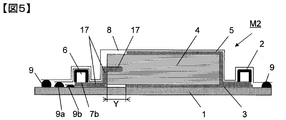
- FIG. 5 is a schematic cross-sectional view of another example of a mold for carrying out the method for producing a fiber reinforced plastic using the RTM molding method of the present invention.
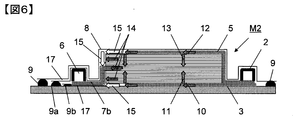
- FIG. 6 is a schematic diagram showing the state of injection and impregnation of the resin into the laminate in the mold of FIG.
- FIG. 7 is a schematic cross-sectional view of another example of a mold for carrying out the method for producing a fiber-reinforced plastic using the RTM molding method of the present invention.
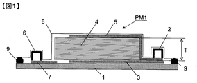
- FIG. 1 is a schematic cross-sectional view of a molding die PM1 for carrying out a fiber reinforced plastic manufacturing method using a conventional RTM molding method.
- a molding die PM1 has a lower die 1 of the molding die PM1 at its base.
- a laminate 4 in which a plurality of reinforcing fiber base materials are laminated is located on the inner surface side (upper surface side in the figure) of the lower mold 1.
- a resin injection port 2 is provided at a position between the right end of the laminate 4 and the right end of the lower mold 1.
- a resin suction port (vacuum suction port) 6 is provided at a position between the left end portion.
- a bagging film 8 is positioned above the lower mold 1 so as to cover the laminate 4, the resin injection port 2 and the resin suction port 6.
- the bagging film 8 corresponds to the upper mold of the mold PM1.
- An internal space of the molding die PM1 is formed between the inner surface of the lower mold 1 and the inner surface of the bagging film (upper mold) 8.
- a sealing material 9 is provided between the peripheral edge of the inner surface of the lower mold 1 and the peripheral edge of the inner surface of the bagging film 8.
- the internal space of the molding die PM1 is a sealed space with respect to the outside by the sealing material 9.
- a lower surface side resin diffusion medium (resin diffusion medium (back)) 3 connected to the resin injection port 2 is provided between the inner surface (upper surface) of the lower mold 1 and the lower surface of the laminate 4, and a bagging film
- An upper surface side resin diffusion medium (resin diffusion medium (table)) 5 connected to the resin injection port 2 is provided between the inner surface of 8 and the upper surface of the laminate 4.
- a resin suction medium 7 connected to the resin suction port 6 is provided along the inner surface (upper surface) of the lower mold 1 between the inner surface (upper surface) of the lower mold 1 and the lower surface of the laminate 4.
- the laminate 4 is located in a sealed space surrounded by the lower die 1, the bagging film 8, and the sealing material 9.
- the injection of the resin into the laminate 4 in the molding die PM1 is performed by sucking the gas inside the molding die PM1 through the resin suction port 6 by a vacuum pump or the like, thereby allowing the molding die PM1 to pass through the resin suction medium 7.
- the inside is reduced in pressure, and the resin is injected from the resin injection port 2 into the laminate 4 through the lower surface side resin diffusion medium 3 and the upper surface side resin diffusion medium 5.
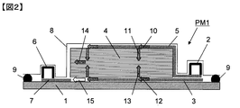
- FIG. 2 is a schematic view showing the state of injection and impregnation of the resin into the laminate in the mold PM1 of FIG.
- the injected resin is diffused along the upper surface side resin diffusion medium 5 as indicated by an arrow 10 at the place where the upper surface side resin diffusion medium 5 is disposed, and the lower surface side resin diffusion medium is also diffused.
- the medium 3 is diffused along the lower surface side resin diffusion medium 3 at the location where the medium 3 is disposed.
- the diffused resin is impregnated from the upper surface and the lower surface of the laminate 4 into the inside of the laminate 4 in the thickness direction of the laminate 4, that is, in the directions indicated by the arrows 11 and 13.
- the portion where the space between the inner surface of the bagging film 8 and the upper surface of the laminate 4 is shown as blank there is no resin diffusion medium, and therefore no resin is supplied to the laminate 4 by the resin diffusion medium. Therefore, only the resin impregnated inward of the laminated body 4 is impregnated in the in-plane direction of the reinforcing fiber substrate forming the laminated body 4 at a place where the resin diffusion medium does not exist.
- this state is schematically indicated by an arrow 14.
- the resin suction medium 7 is disposed between the reinforcing fiber base layers of the laminate 4 or the laminate 4.
- the resin passing through the flow path of the resin by the short path indicated by the arrow 15 is more than the resin passing through the flow path indicated by the arrow 14 because the resin is not disposed in contact with the surface (side surface) of the side end of the resin.
- the resin passes through the short path indicated by the arrow 15 before the impregnation is completed in the thickness direction of the laminated body 4 at the place where the lower surface side resin diffusion medium 3 and the upper surface side resin diffusion medium 5 are not present. It passes through and is sucked into the resin suction medium 7. As a result, there is a problem that an unimpregnated portion of the resin is generated inside the laminate 4.
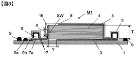
- FIG. 3 is a schematic cross-sectional view of a molding die M1, which is an example of a molding die for carrying out a method for producing a fiber reinforced plastic using the RTM molding method of the present invention.
- a molding die M1 which is an example of a molding die for carrying out a method for producing a fiber reinforced plastic using the RTM molding method of the present invention.
- FIG. 3 the same members as those shown in FIG. 1 are denoted by the same reference numerals.
- the mold M1 has a resin injection port 2 at one end and a resin suction port (vacuum suction port) 6 at the other end.
- a laminate 4 made of a laminate of a plurality of reinforcing fiber substrates is accommodated in the internal space of the mold M1.
- Resin diffusion media 3 and 5 are provided along both opposing surfaces of the laminate 4 (in the drawing, the upper surface and the lower surface of the laminate 4) extending from the resin injection port 2.
- the resin is supplied from the resin injection port 2 to both opposing surfaces of the laminate 4 through the resin diffusion media 3 and 5.
- the gas or resin from the laminate 4 extends from the resin suction port 6, contacts the side surface of the laminate 4 on the resin suction port 6 side, or is in contact with the side surface, or is spaced from the side surface.
- the resin suction medium 7a is provided in a state where suction is possible. The gas or resin sucked from the laminate 4 moves toward the resin suction port 6 through the resin suction medium 7a.
- the gas in the internal space of the mold M1 is sucked from the resin suction port 6 through the resin suction medium 7a, and the internal space of the mold M1 is depressurized.
- the resin is injected into the laminate 4, and a part of the resin injected into the laminate 4 is moved toward the resin suction port 6 through the resin suction medium 7 a, so that the laminate 4 is impregnated with the resin.
- a fiber reinforced plastic is manufactured by solidifying the resin impregnated in the laminate 4. The manufactured fiber reinforced plastic is taken out from the molding die M1 and used as a molded product as it is or after finishing.
- the mold M1 has a lower mold 1 of the mold M1 at the base.
- a laminate 4 in which a plurality of reinforcing fiber base materials are laminated is located on the inner surface side of the lower mold 1 (upper surface side in FIG. 3).
- a resin injection port 2 is provided at a position between the right end of the laminate 4 and the right end of the lower mold 1.
- a resin suction port (vacuum suction port) 6 is provided at a position between the left end portion.
- a bagging film 8 is positioned above the lower mold 1 so as to cover the laminate 4, the resin injection port 2 and the resin suction port 6.
- the bagging film 8 corresponds to the upper mold of the mold M1.
- An internal space of the mold M1 is formed between the inner surface of the peripheral edge of the inner surface of the lower mold 1 and the peripheral edge of the inner surface of the bagging film 8.
- a lower surface side resin diffusion medium (resin diffusion medium (back)) 3 connected to the resin injection port 2 is provided between the inner surface (upper surface) of the lower mold 1 and the lower surface of the laminate 4, and a bagging film
- An upper surface side resin diffusion medium (resin diffusion medium (table)) 5 connected to the resin injection port 2 is provided between the inner surface of 8 and the upper surface of the laminate 4.
- a resin suction medium 7 a connected to the resin suction port 6 is provided between the inner surface (upper surface) of the lower mold 1 and the inner surface of the bagging film 8.
- the portion of the resin suction medium 7a facing the end opposite to the resin suction port 6 is a laminate opposite to the side surface of the laminate 4 on the side where the resin injection port 2 is located (the right side surface in FIG. 3). 4 extends upward along the side surface 4 (the surface of the left side wall SW in FIG. 3), between the side surface of the laminate 4 and the inner surface of the bagging film 8, and in at least a partial region of the side surface of the laminate 4. In a state where the resin can be sucked from the laminated body 4, it faces the side surface of the laminated body 4 and is in contact with the side surface of the laminated body 4 as necessary.
- the laminate 4 is located in a sealed space surrounded by the lower mold 1, the bagging film 8, and the seal portion 9.
- the injection of the resin into the laminate 4 in the mold M1 is performed by sucking the gas inside the mold M1 through the resin suction port 6 by a vacuum pump or the like, and thereby via the resin suction medium 7a.
- the inside is reduced in pressure, and the resin is injected from the resin injection port 2 into the laminate 4 through the lower surface side resin diffusion medium 3 and the upper surface side resin diffusion medium 5.
- the resin suction medium 7a is preferably arranged over the entire length of the side surface formed by the thickness of the laminated body 4 so as to include the central portion of the thickness of the laminated body 4. Further, a sealing fixing material 16 is attached to the resin suction medium 7a at the suction location at the center of the side surface formed by the thickness of the laminate 4, that is, at the upper and lower positions of the area X shown in FIG. It is preferable. Moreover, it is preferable that the resin suction medium 7a is covered with the airtight material 17 including both surfaces or side surfaces of portions other than the suction portion.
- an elastic seal such as an adhesive tape or sealant may be used.
- silicone rubber in order to increase the stability of the shape after vacuum suction, or in consideration of releasability after molding. It is preferable to use silicone rubber.
- the sealing fixing material 16 is arranged between the resin suction medium 7a and the side surface formed by the thickness of the laminated body 4 so as not to seal the portion corresponding to the thickness central portion of the laminated body, and its length is A slit-shaped resin suction port having a height of 0.1 to 5 mm is opened in the central portion in order to form a portion having the same length as the thickness of the laminate and not sealed.
- the width is preferably 0.1 to 50 mm.
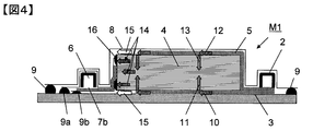
- the resin suction medium 7a is disposed at the center of the side surface formed by the thickness of the laminate, so that the layers are laminated through the resin diffusion media 3 and 5.
- the resin impregnated in the thickness direction of the body 4 is impregnated in the direction indicated by the arrow 14 (in-plane direction) by suction of the resin suction medium 7a, and the resin diffusion media 3 and 5 are not disposed (resin diffusion).
- the portion of the laminate 4 at the position corresponding to the medium non-existing area Y) can also be impregnated with the resin, and the occurrence of the unimpregnated portion of the resin can be greatly suppressed.
- the resin impregnated in the thickness direction of the laminate (the resin indicated by arrows 11 and 13). Since the flow confluence is at the center of the thickness of the laminate 4, the arrangement of the resin suction medium 7 a where the resin can be sucked is preferably at the center of the thickness of the laminate 4.
- the laminate is composed of a plurality of types of reinforcing fiber bases such as types of reinforcing fibers, basis weight, and woven structure are different, and the laminated configuration is not symmetrical with respect to the thickness direction, Since the impregnation rate in the thickness direction depends on the impregnation property of each reinforcing fiber base constituting the laminate, it is not necessarily the same. As a result, the location where the resin impregnated in the laminate joins is not necessarily laminated. It is not always the center of the body thickness.
- the location of the resin suction medium 7a where the resin can be sucked is determined by confirming in advance the location where the resin impregnation joins by a resin impregnation test or the like on the laminate. Good to do.
- the resin suction medium 7a is confirmed so as to include the layers where the resin is merged by confirming the merge point of the resin estimated based on analysis results such as impregnation calculation or impregnation simulation using FEM (Finite Element Element Method). It is preferable to position a portion where the resin suction is possible.
- the resin suction medium 7a is covered with the airtight material 17 at portions other than the suction portion of the laminate 4, so that the resin injected from the resin diffusion media 3 and 5 is the laminate 4. It is possible to suppress the formation of a short path (short path indicated by an arrow 15) that is not impregnated into the resin and is sucked into the resin suction medium 7a, and greatly suppresses the occurrence of a resin non-impregnated portion in the laminated body 4. be able to.
- the airtight material provided on the inner surface of the bagging film 8 of the resin suction medium 7a extends in the direction of the resin suction port 6 along the resin suction medium 7a, covers the resin suction port 6, and covers the end of the lower mold.
- the sealing material 9a is provided between the peripheral end portion of the lower surface of the airtight material and the terminal portion of the upper surface of the lower mold 1, and the airtight material and the lower mold 1 are hermetically sealed. Has been.
- the airtight material provided on the surface of the resin suction medium 7a opposite to the surface located on the inner surface side of the bagging film 8 extends along the resin suction medium 7a in the direction of the resin suction port 6.
- the sealing material 9b is provided between the peripheral end portion of the lower surface of the hermetic material and the terminal end portion of the upper surface of the lower die. The space between the material and the lower mold 1 is hermetically sealed.
- the upper surface of the resin suction medium 7a positioned at the resin suction port 6 is opened so that gas or resin can flow through the resin suction port 6, and the lower surface of the resin suction medium 7a positioned at the resin suction port 6 is airtight. Depending on the material, the gas or resin cannot be circulated from the outside.
- the resin is not present in the resin diffusion medium absence area Y. If not impregnated, the resin is not immediately sucked from the resin suction medium 7a.
- the impregnation time in the thickness direction of the resin varies within the laminate, and it is not necessarily from the resin inlet 2 side of the laminate. Sequential impregnation is not always completed. For this reason, it is possible that the resin reaches the resin suction medium 7a and is sucked in a state where an unimpregnated portion of the resin is left inside the laminate.
- the resin diffusion medium absence area Y by providing the resin diffusion medium absence area Y, the resin is impregnated from the resin diffusion media 3 and 5 in the thickness direction of the laminate and merged, and then the resin diffusion medium absence area Y is formed in the in-plane direction. After impregnating only the length, the resin is sucked by the resin suction medium 7a. Therefore, even if a resin non-impregnated portion is generated inside the laminate after unexpected resin merging, use the time until the resin reaches the resin suction medium 7a after merging, The impregnation of the resin in the non-impregnated portion of the resin can be completed.
- FIGS. 5 and 6 a method for producing the fiber reinforced plastic of the present invention in which the mold M2 of a different form from the mold M1 shown in FIG. 3 is used will be described.
- members that are the same as those shown in FIG. 3 are given the same reference numerals.
- FIG. 5 is a schematic cross-sectional view of a molding die M2 as another example of a molding die for carrying out the fiber reinforced plastic manufacturing method using the RTM molding method of the present invention.
- the difference between the mold M2 shown in FIG. 5 and the mold M1 shown in FIG. 3 lies in the arrangement of the resin suction medium provided along the side surface of the laminate 4 where the resin suction port 6 is located. .
- the front end portion of the resin suction medium 7b extending upward along the side surface of the laminated body 4 is bent from the side surface of the laminated body 4 and inserted between the reinforcing fiber base materials of the laminated body. Yes.
- the arrangement of the resin suction medium in the mold M2 and the mold M1 is different.
- the laminate is passed through the resin diffusion media 3 and 5.
- the resin impregnated in the thickness direction 4 moves while being impregnated in the direction indicated by the arrow 14 by the resin suction medium 7b, and the resin diffusion media 3 and 5 are not arranged, that is, the resin diffusion medium absence area. It is possible to impregnate the layered body portion at a position corresponding to Y, and the generation of the unimpregnated portion of the resin can be significantly suppressed.
- the resin diffusion medium absence area Y in the mold M2 in FIG. 5 has the same function as the resin diffusion medium absence area Y in the mold M1 in FIG. Therefore, even when the resin suction medium 7b is not inserted between the layers of the reinforcing fiber base, the resin is sucked from the resin suction medium 7b after a time required for the resin to completely impregnate the laminate. . Even when an unexpected unimpregnation of the resin occurs during the resin injection and impregnation, the resin diffusion medium absence area Y is provided, so that sufficient time until the resin is sucked can be secured. Over time, resin impregnation reaches the unimpregnated portion of the resin, and after the resin impregnation is completed, the resin is sucked toward the resin suction port 6 through the resin suction medium 7b.
- the resin suction medium 7b is covered with an airtight material 17 at a portion where no gas or resin is sucked from the laminate 4.
- an airtight material 17 at a portion where no gas or resin is sucked from the laminate 4.
- the airtight material 17 is not particularly limited as long as it is a material that can keep gas tightness, and among them, the same material as the bagging film is preferably used. As shown in FIG. 5, the airtight material 17 is disposed on the upper surface of the resin suction medium 7b, covers the resin suction port (resin suction port) 6, and closes the lower mold 1 with the sealing material 9a. Even if the resin that has unexpectedly diffused from the upper resin diffusion medium 5 forms a short path as indicated by an arrow 15 in FIG. 6, the resin is not directly sucked by the resin suction medium 7b. Since the resin is first sucked by the resin suction medium 7b after being impregnated in the thickness direction of the laminate 4, the resin impregnation property of the laminate 4 can be improved.
- the resin that has unexpectedly diffused from the lower resin diffusion medium 3 is In FIG. 6, even if a short path as shown by the arrow 15 is formed, the resin is not directly sucked by the resin suction medium 7b. Since the resin is first sucked by the resin suction medium 7b after being impregnated in the thickness direction of the laminate 4, the resin impregnation property of the laminate 4 can be improved.
- the fiber-reinforced plastic manufacturing method using the mold M2 shown in FIG. 5 accommodates the laminate in the inner space of the mold compared to the fiber-reinforced plastic manufacturing method using the mold M1 shown in FIG. In this case, since the resin suction medium 7b can be easily disposed on the side surface of the laminated body, the manufacturing cycle time can be shortened.
- the reinforcing fiber substrate As the reinforcing fiber substrate, a carbon fiber substrate in which carbon fibers (carbon fiber manufactured by Toray Industries, Inc .: T620SC-24000) were arranged in one direction and the basis weight of the carbon fiber was 600 g / m 2 was used. A laminate was prepared in which 50 carbon fiber base materials were aligned in one direction and laminated.
- This laminate was placed on the lower mold 1 of the mold M1 as shown in FIG.
- the upper surface side resin diffusion medium 5, the lower surface side resin diffusion medium 3, and the resin suction medium 7a are all made of the same polypropylene mesh, and the shape of each gap of the mesh is 2.5 mm on a side and the thickness is about 0.6 mm. I used one.
- the upper surface side resin diffusion medium 3 and the lower surface side resin diffusion medium 5 were arranged so that the length in the longitudinal direction of the laminate 4 of the resin diffusion medium absence area Y shown in FIG. 3 was 10 mm.
- the resin suction medium 7a has a total length of the side surface formed by the thickness of the laminated body 4 so as to come into contact with the central portion in the thickness direction of the side surface (side wall SW) formed by the thickness of the laminated body 4. Arranged over.
- the sealing and fixing material 16 was arranged at the upper and lower positions sandwiching the central portion, and the area X in direct contact with the side surface formed by the thickness of the laminate 4 was arranged to be 5 mm.
- the airtight material 17 was arranged on both surfaces of the resin suction medium 7a and sealed with the lower mold 1 of the mold M1 using the sealing materials 9a and 9b.
- a polyamide bagging film having a thickness of about 50 ⁇ m was used as the airtight material 17.
- the whole was covered with a bagging film 8 and sealed with a sealing material 9 between the lower mold 1 of the mold M1.
- the same sealing material was used for the sealing material 9 and the sealing fixing material 16.
- the epoxy resin is a resin of a two-component mixture of a main agent and a curing agent, and the viscosity of the resin has an initial viscosity of about 160 mPas and has a tendency to thicken about twice after 60 minutes.
- the laminate 4 impregnated with resin is heated for 24 hours at room temperature and 15 hours at 60 ° C. using an oven with the resin injection port 2 and the resin suction port (vacuum suction port) 6 closed. The resin was cured. After the resin was cured, the molded body molded in the molding die M1 was removed from the molding die M1.
- the manufactured fiber-reinforced plastic molded body was cut over the entire length at the center in the width direction, and the cut surface was observed. As a result, it was confirmed that there were no unimpregnated portions of the resin.
- FIG. 7 is a schematic cross-sectional view of a molding die M3 as another example of a molding die for carrying out a method for producing a fiber-reinforced plastic using the RTM molding method of the present invention.
- the difference between the mold M3 shown in FIG. 7 and the mold M1 shown in FIG. 3 is that the sealing fixing material 16 in the latter mold M1 is the entire side surface of the laminate in the former mold M3.
- the resin suction medium 7c having an opening (window) provided in the central portion in the vertical direction of the sealing fixing material 16 and having an airtight material on both sides is provided on the side surface of the laminate 4 of the sealing fixing material 16. It is a point provided along the surface (outer surface) opposite to the surface in contact.
- Both sides of the resin suction medium 7c are covered with the airtight material 17, but the airtight material 17 has a similar opening (window) at a location facing the opening (window) portion of the sealing fixing material 16. ing. Through the opening (window) of the sealing fixing material 16 and the opening (window) of the airtight material 17, the resin impregnated in the laminate 4 is sucked into the resin suction medium 7c.
- a molded product of fiber reinforced plastic was produced in the same manner as in Example 1 using the molding die M3 shown in FIG.
- the manufactured molded body was cut in the same manner as in Example 1 and the cut surface was observed. As a result, it was confirmed that the molded body had no unimpregnated portion of resin.
- a molded product of fiber reinforced plastic was produced in the same manner as in Example 1 using the molding die PM1 shown in FIG.
- the manufactured molded body was cut in the same manner as in Example 1 and the cut surface was observed.
- the lower surface of the laminated body 4 facing the lower resin diffusion medium 3 from the center in the thickness direction of the laminated body 4 It was confirmed that an unimpregnated portion of the resin exists in a wide range up to a position close to.
Abstract
Description
v=-K・∇P/μ ・・・・・(1)
で表される。 If it is assumed that the resin impregnation into the reinforcing fiber base in the RTM method or VaRTM method follows Darcy's law, the resin flow velocity v (m / s) indicates the ease of impregnation of the resin into the reinforcing fiber base. Using the permeabilities K (m), the pressure P (Pa) of the resin, and the viscosity μ (Pa · s) of the resin, which are indicators,
v = -K · ∇P / μ (1)
It is represented by
(b)該成形型の内部空間に、複数枚の強化繊維基材の積層からなる積層体が収容され、
(c)前記樹脂注入口から延び、前記積層体の対向する両表面に沿って設けられ、前記樹脂注入口から前記積層体の対向する両表面に樹脂を供給する樹脂拡散媒体と
(d)前記樹脂吸引口から延び、該樹脂吸引口側の前記積層体の側面に沿って、該側面に接触して、あるいは、該側面に対して間隔をおいて、前記積層体からの気体あるいは樹脂の吸引が可能な状態に設けられ、前記積層体から気体あるいは樹脂を前記樹脂吸引口に向い移動させる樹脂吸引媒体が用いられ、
(e)前記樹脂吸引口から前記樹脂吸引媒体を通じて前記成形型の内部空間の気体が吸引され、前記成形型の内部空間が減圧された後、
(f)前記樹脂注入口から前記樹脂拡散媒体を通じて前記積層体に樹脂が注入され、
(g)前記積層体に注入された樹脂の一部が、前記樹脂吸引媒体を通じて前記樹脂吸引口に向って移動することにより、前記積層体に樹脂が含浸されてなる繊維強化プラスチックの製造方法。 (A) A mold having a resin injection port at one end and a resin suction port at the other end is used.
(B) A laminate composed of a laminate of a plurality of reinforcing fiber substrates is accommodated in the internal space of the mold,
(C) a resin diffusion medium extending from the resin injection port and provided along both opposing surfaces of the laminate, and supplying resin from the resin injection port to both opposing surfaces of the laminate; Suction of gas or resin from the laminate extending from the resin suction port, in contact with the side surface of the laminate on the resin suction port side, or in contact with the side surface, or spaced from the side surface A resin suction medium is used that is provided in a state that allows gas or resin to move from the laminate toward the resin suction port,
(E) After the gas in the internal space of the mold is sucked from the resin suction port through the resin suction medium and the internal space of the mold is decompressed,
(F) resin is injected into the laminate through the resin diffusion medium from the resin injection port;
(G) A method for producing a fiber reinforced plastic in which a part of the resin injected into the laminate moves toward the resin suction port through the resin suction medium, so that the laminate is impregnated with resin.
積層体が、強化繊維が一方向にのみ配列されている強化繊維基材からなる場合、顕著な効果が期待できるため好ましい。強化繊維が一方向にのみに配列されている強化繊維基材からなる積層体は、強化繊維がそれぞれ異なる角度に一方向に配列さている強化繊維基材が積層された積層体(例えば、厚み方向に積層された4層が上下対称の形で積層された8層の積層体[45°/0°/-45°/90°]Sなど)に比べて、強化繊維をより密に配列することができる。しかし、トレードオフの関係で、積層体の樹脂の含浸性は低下する傾向にある。 However, in this case, the resin is hardened and molded in a state where the tip of the resin suction medium is inserted between the layers of the reinforcing fiber base material forming the laminate, so that the resin is placed inside the fiber reinforced plastic after molding. There is a problem that the suction medium remains. When there is no problem even if the resin diffusion medium remains inside the fiber reinforced plastic, or when the resin diffusion medium is removed by cutting or the like after molding, a method of inserting the tip of the resin suction medium between the layers may be applied. it can.
When a laminated body consists of a reinforced fiber base material in which reinforcing fibers are arranged only in one direction, it is preferable because a remarkable effect can be expected. A laminate composed of reinforcing fiber substrates in which reinforcing fibers are arranged only in one direction is a laminate in which reinforcing fiber substrates in which reinforcing fibers are arranged in one direction at different angles are laminated (for example, in the thickness direction). The reinforcing fibers are arranged more densely than an eight-layer laminate (45 ° / 0 ° / −45 ° / 90 °, etc. S ) in which four layers laminated on each other are laminated in a vertically symmetrical manner. Can do. However, the resin impregnation property of the laminate tends to decrease due to a trade-off relationship.
2:樹脂注入口
3:下面側樹脂拡散媒体(樹脂拡散媒体(裏))
5:上面側樹脂拡散媒体(樹脂拡散媒体(表))
4:積層体
6:樹脂吸引口(真空吸引口)
7、7a、7b、7c:樹脂吸引媒体
8:バギングフィルム
9、9a、9b:シール材
10、11、12、13、14、15:矢印
16:封止固定材
17:気密材料
M1、M2、M3:成形型
PM1:成形型
SW:樹脂注入口と反対側に位置する積層体の厚みによって形成される側壁
X:樹脂吸引媒体の積層体の厚みが形成する側壁(側面)に直接接触する部分(区域)
Y:樹脂拡散媒体不存在区域 1:
5: Upper surface side resin diffusion medium (resin diffusion medium (table))
4: Laminate 6: Resin suction port (vacuum suction port)
7, 7a, 7b, 7c: Resin suction medium 8: Bagging
Y: Resin diffusion medium absence area
Claims (13)
- (a)一端に樹脂注入口、他端に樹脂吸引口を有する成形型が用いられ、
(b)該成形型の内部空間に、複数枚の強化繊維基材の積層からなる積層体が収容され、
(c)前記樹脂注入口から延び、前記積層体の対向する両表面に沿って設けられ、前記樹脂注入口から前記積層体の対向する両表面に樹脂を供給する樹脂拡散媒体と
(d)前記樹脂吸引口から延び、該樹脂吸引口側の前記積層体の側面に沿って、該側面に接触して、あるいは、該側面に対して間隔をおいて、前記積層体からの気体あるいは樹脂の吸引が可能な状態に設けられ、前記積層体から気体あるいは樹脂を前記樹脂吸引口に向い移動させる樹脂吸引媒体が用いられ、
(e)前記樹脂吸引口から前記樹脂吸引媒体を通じて前記成形型の内部空間の気体が吸引され、前記成形型の内部空間が減圧された後、
(f)前記樹脂注入口から前記樹脂拡散媒体を通じて前記積層体に樹脂が注入され、
(g)前記積層体に注入された樹脂の一部が、前記樹脂吸引媒体を通じて前記樹脂吸引口に向って移動することにより、前記積層体に樹脂が含浸されてなる繊維強化プラスチックの製造方法。 (A) A mold having a resin injection port at one end and a resin suction port at the other end is used.
(B) A laminate composed of a laminate of a plurality of reinforcing fiber substrates is accommodated in the internal space of the mold,
(C) a resin diffusion medium extending from the resin injection port and provided along both opposing surfaces of the laminate, and supplying resin from the resin injection port to both opposing surfaces of the laminate; Suction of gas or resin from the laminate extending from the resin suction port, in contact with the side surface of the laminate on the resin suction port side, or in contact with the side surface, or spaced from the side surface A resin suction medium is used that is provided in a state that allows gas or resin to move from the laminate toward the resin suction port,
(E) After the gas in the internal space of the mold is sucked from the resin suction port through the resin suction medium and the internal space of the mold is decompressed,
(F) resin is injected into the laminate through the resin diffusion medium from the resin injection port;
(G) A method for producing a fiber reinforced plastic in which a part of the resin injected into the laminate moves toward the resin suction port through the resin suction medium, so that the laminate is impregnated with resin. - 前記樹脂吸引媒体が、前記積層体の対向する両表面から前記積層体内に含浸した樹脂が合流する領域に位置する前記強化繊維基材が存在する前記積層体の側面に向かい合っている請求項1に記載の繊維強化プラスチックの製造方法。 The said resin suction medium is facing the side surface of the said laminated body in which the said reinforced fiber base material located in the area | region where the resin impregnated in the said laminated body merges from the both surfaces which the said laminated body opposes. The manufacturing method of the fiber reinforced plastic of description.
- 前記樹脂吸引媒体が、前記積層体の厚み中央部に位置する前記強化繊維基材が存在する前記積層体の側面に向かい合っている請求項1に記載の繊維強化プラスチックの製造方法。 The method for producing a fiber-reinforced plastic according to claim 1, wherein the resin suction medium faces a side surface of the laminate in which the reinforcing fiber substrate located at a central portion of the thickness of the laminate is present.
- 前記樹脂吸引媒体が、前記成形型の内面と前記積層体の側面との間において、封止固定材により成形型に固定されている請求項1に記載の繊維強化プラスチックの製造方法。 The method for producing a fiber-reinforced plastic according to claim 1, wherein the resin suction medium is fixed to the mold with a sealing fixing material between the inner surface of the mold and the side surface of the laminate.
- 前記封止固定材が、前記積層体の厚みとほぼ同じ高さを有し、前記積層体の厚み中央部に対応する位置において、高さが0.1乃至5mm、幅が0.1乃至50mmの樹脂吸引口を有する請求項4に記載の繊維強化プラスチックの製造方法。 The sealing fixing material has substantially the same height as the thickness of the laminate, and the height is 0.1 to 5 mm and the width is 0.1 to 50 mm at a position corresponding to the thickness central portion of the laminate. The manufacturing method of the fiber reinforced plastics of Claim 4 which has the resin suction port of this.
- 前記樹脂吸引媒体が存在している側の前記積層体の側面の位置まで、前記樹脂注入口から延びている前記樹脂拡散媒体が延びることなく、前記成形型の内面と前記積層体の表面との間に、樹脂拡散媒体不存在区域が設けられている請求項1に記載の繊維強化プラスチックの製造方法。 Without the resin diffusion medium extending from the resin injection port extending to the position of the side surface of the laminate on the side where the resin suction medium exists, the inner surface of the mold and the surface of the laminate The method for producing a fiber reinforced plastic according to claim 1, wherein a resin diffusion medium absence area is provided therebetween.
- 前記樹脂吸引媒体が、前記積層体から樹脂を吸引する領域以外の領域において、その表面が気密材料で覆われ、樹脂の吸引に対し遮蔽された部分を有する請求項1に記載の繊維強化プラスチックの製造方法。 2. The fiber-reinforced plastic according to claim 1, wherein the resin suction medium has a portion whose surface is covered with an airtight material and shielded against suction of the resin in a region other than a region where the resin is sucked from the laminate. Production method.
- 前記樹脂拡散媒体の樹脂流動抵抗が、前記強化繊維基材の樹脂流動抵抗の1/10以下である請求項1に記載の繊維強化プラスチックの製造方法。 The method for producing a fiber reinforced plastic according to claim 1, wherein the resin flow resistance of the resin diffusion medium is 1/10 or less of the resin flow resistance of the reinforcing fiber substrate.
- 前記樹脂吸引媒体の樹脂流動抵抗が、前記強化繊維基材の樹脂流動抵抗の1/3以下である請求項1に記載の繊維強化プラスチックの製造方法。 The method for producing a fiber-reinforced plastic according to claim 1, wherein the resin flow resistance of the resin suction medium is 1/3 or less of the resin flow resistance of the reinforcing fiber base.
- 前記樹脂吸引媒体の先端部が、前記積層体の強化繊維基材の層間に挿入されている請求項1に記載の繊維強化プラスチックの製造方法。 The method for producing a fiber-reinforced plastic according to claim 1, wherein a tip portion of the resin suction medium is inserted between layers of the reinforcing fiber base of the laminate.
- 前記樹脂吸引媒体の少なくとも一部が、成形された繊維強化プラスチックから除去されてなる請求項1に記載の繊維強化プラスチックの製造方法。 The method for producing a fiber reinforced plastic according to claim 1, wherein at least a part of the resin suction medium is removed from the molded fiber reinforced plastic.
- 前記樹脂吸引媒体の少なくとも一部が、前記積層体内に残存せしめられてなる請求項10に記載の繊維強化プラスチックの製造方法。 The method for producing a fiber-reinforced plastic according to claim 10, wherein at least a part of the resin suction medium is left in the laminated body.
- 前記積層体を形成している前記強化繊維基材が、一方向に配列された強化繊維からなる請求項1に記載の繊維強化プラスチックの製造方法。 The method for producing a fiber-reinforced plastic according to claim 1, wherein the reinforcing fiber base material forming the laminate is composed of reinforcing fibers arranged in one direction.
Priority Applications (7)
| Application Number | Priority Date | Filing Date | Title |
|---|---|---|---|
| BR112013005859A BR112013005859A2 (en) | 2010-09-24 | 2011-09-21 | method for producing fiber-reinforced plastic |
| CN2011800428381A CN103097099A (en) | 2010-09-24 | 2011-09-21 | Method for producing fiber-reinforced plastic |
| KR1020137009107A KR20130111552A (en) | 2010-09-24 | 2011-09-21 | Method for producing fiber-reinforced plastic |
| US13/825,359 US9205602B2 (en) | 2010-09-24 | 2011-09-21 | Method for producing fiber-reinforced plastic |
| EP11826854.9A EP2620265A4 (en) | 2010-09-24 | 2011-09-21 | Method for producing fiber-reinforced plastic |
| RU2013118703/05A RU2013118703A (en) | 2010-09-24 | 2011-09-21 | METHOD FOR PRODUCING FIBER REINFORCED PLASTIC |
| CA2810699A CA2810699A1 (en) | 2010-09-24 | 2011-09-21 | Method for producing fiber-reinforced plastic |
Applications Claiming Priority (4)
| Application Number | Priority Date | Filing Date | Title |
|---|---|---|---|
| JP2010-213245 | 2010-09-24 | ||
| JP2010213245 | 2010-09-24 | ||
| JP2011047459A JP5533743B2 (en) | 2010-09-24 | 2011-03-04 | Manufacturing method of fiber reinforced plastic |
| JP2011-047459 | 2011-03-04 |
Publications (1)
| Publication Number | Publication Date |
|---|---|
| WO2012039409A1 true WO2012039409A1 (en) | 2012-03-29 |
Family
ID=45873893
Family Applications (1)
| Application Number | Title | Priority Date | Filing Date |
|---|---|---|---|
| PCT/JP2011/071426 WO2012039409A1 (en) | 2010-09-24 | 2011-09-21 | Method for producing fiber-reinforced plastic |
Country Status (9)
| Country | Link |
|---|---|
| US (1) | US9205602B2 (en) |
| EP (1) | EP2620265A4 (en) |
| JP (1) | JP5533743B2 (en) |
| KR (1) | KR20130111552A (en) |
| CN (1) | CN103097099A (en) |
| BR (1) | BR112013005859A2 (en) |
| CA (1) | CA2810699A1 (en) |
| RU (1) | RU2013118703A (en) |
| WO (1) | WO2012039409A1 (en) |
Cited By (3)
| Publication number | Priority date | Publication date | Assignee | Title |
|---|---|---|---|---|
| EP2840173A1 (en) | 2012-04-18 | 2015-02-25 | Mitsubishi Rayon Co., Ltd. | Carbon fiber bundle and method of producing carbon fiber bundle |
| US20150099103A1 (en) * | 2013-10-04 | 2015-04-09 | Rohr, Inc. | Variable matrix composite |
| JP2016221734A (en) * | 2015-05-28 | 2016-12-28 | 三菱航空機株式会社 | Seal structure in VaRTM method |
Families Citing this family (18)
| Publication number | Priority date | Publication date | Assignee | Title |
|---|---|---|---|---|
| EP2700492B1 (en) * | 2012-08-23 | 2017-02-01 | Airbus Operations GmbH | Infusion method and structure for infusion method |
| DK2762297T3 (en) | 2013-02-05 | 2019-01-07 | Siemens Ag | Pressure sensitive power distribution medium for VARTM |
| US9738011B2 (en) | 2014-05-20 | 2017-08-22 | The Boeing Company | Concurrent infusion of dissimilar resins |
| CN104441687A (en) * | 2014-09-17 | 2015-03-25 | 重庆海电风能集团有限公司 | RTM manufacture process of wind power cabin cover |
| CN106142593B (en) * | 2015-04-10 | 2019-11-26 | 科思创德国股份有限公司 | The method for manufacturing article of fiber reinforced plastics |
| JP6537921B2 (en) * | 2015-08-06 | 2019-07-03 | 三菱重工業株式会社 | Apparatus for producing fiber-reinforced plastic, movable base, method for producing shaped fiber substrate, and method for producing fiber-reinforced plastic |
| AU2016203289B2 (en) * | 2016-05-20 | 2022-04-07 | The Boeing Company | A method and system for resin infusing a composite preform |
| MA45359A (en) * | 2016-06-14 | 2019-04-17 | Lm Wp Patent Holding As | WIND TURBINE BLADE MANUFACTURING PROCESS |
| WO2018030470A1 (en) * | 2016-08-09 | 2018-02-15 | 三菱重工業株式会社 | Method for producing fiber-reinforced resin molded articles |
| JP6604322B2 (en) * | 2016-12-28 | 2019-11-13 | トヨタ自動車株式会社 | Method for producing fiber-reinforced resin molded body |
| US10786957B2 (en) | 2017-01-30 | 2020-09-29 | General Electric Company | System, method, and apparatus for infusing a composite structure |
| JP7085803B2 (en) * | 2017-04-28 | 2022-06-17 | 三菱重工業株式会社 | Composite material molding method and composite material molding equipment |
| US11225942B2 (en) | 2017-07-05 | 2022-01-18 | General Electric Company | Enhanced through-thickness resin infusion for a wind turbine composite laminate |
| US10730236B2 (en) | 2017-08-02 | 2020-08-04 | Ethicon Llc | System and method for additive manufacture of medical devices |
| DE102017128501A1 (en) | 2017-11-30 | 2019-06-06 | Airbus Operations Gmbh | Method for producing a composite component |
| DE102019114329A1 (en) * | 2019-05-28 | 2020-12-03 | Airbus Operations Gmbh | Structure and method for manufacturing components from a plastic or composite material, in particular for aircraft and space vehicles, and auxiliary tools |
| US20220258438A1 (en) * | 2020-03-19 | 2022-08-18 | Mitsubishi Heavy Industries, Ltd. | Method for molding composite material and apparatus for molding composite material |
| CN114454381B (en) * | 2022-02-17 | 2023-02-21 | 浙江金凤凰电力科技有限公司 | Gum dipping device suitable for producing oversized core body by adopting integral pultrusion process |
Citations (8)
| Publication number | Priority date | Publication date | Assignee | Title |
|---|---|---|---|---|
| JP2004181627A (en) * | 2002-10-09 | 2004-07-02 | Toray Ind Inc | Resin transfer molding method |
| JP2004188965A (en) | 2002-11-27 | 2004-07-08 | Mitsubishi Heavy Ind Ltd | Manufacturing process and device for fiber reinforced resin structure |
| JP2005527410A (en) * | 2002-05-29 | 2005-09-15 | ザ・ボーイング・カンパニー | Controlled atmospheric pressure resin injection process |
| JP2005271248A (en) * | 2004-03-23 | 2005-10-06 | Toray Ind Inc | Frp manufacturing method |
| JP2006130733A (en) * | 2004-11-04 | 2006-05-25 | Yokohama Rubber Co Ltd:The | Manufacturing method of fiber reinforced resin molded product |
| JP2007176163A (en) | 2005-11-30 | 2007-07-12 | Toray Ind Inc | Manufacturing process of fiber-reinforced plastic |
| JP2008179149A (en) | 2002-10-09 | 2008-08-07 | Toray Ind Inc | Rtm molding method |
| JP2009045924A (en) * | 2007-07-24 | 2009-03-05 | Toray Ind Inc | Frp production method |
Family Cites Families (12)
| Publication number | Priority date | Publication date | Assignee | Title |
|---|---|---|---|---|
| US4548859A (en) * | 1984-10-12 | 1985-10-22 | The Boeing Company | Breather material and method of coating fabric with silicone rubber |
| US4622091A (en) * | 1984-11-29 | 1986-11-11 | The Boeing Company | Resin film infusion process and apparatus |
| EP0525263B1 (en) * | 1991-08-01 | 1996-03-27 | Scrimp Systems, L.L.C. | Vacuum-forming method and apparatus for vacuum-forming fibre reinforced resin composites |
| US5433165A (en) * | 1994-03-30 | 1995-07-18 | Outboard Marine Corporation | Method of manufacturing a boat hull |
| GB9916157D0 (en) * | 1999-07-10 | 1999-09-08 | British Aerospace | Method for manufacturing a filled hollow fibre composite mate rial |
| US6818159B2 (en) * | 2000-03-17 | 2004-11-16 | Deutsches Zentrum Fuer Luft-Und Raumfahrt E.V. | Process for the production of a composite consisting of a fiber reinforced material |
| DE10140166B4 (en) * | 2001-08-22 | 2009-09-03 | Eads Deutschland Gmbh | Method and device for producing fiber-reinforced components by means of an injection method |
| EP2644365B1 (en) * | 2002-10-09 | 2019-03-27 | Toray Industries, Inc. | Method of RTM molding |
| GB0417634D0 (en) * | 2004-08-09 | 2004-09-08 | Structural Polymer Systems Ltd | Mould |
| EP1990169B1 (en) * | 2006-02-28 | 2018-07-04 | Toray Industries, Inc. | Process for the production of laminates of reinforcing fiber base material |
| GB0702781D0 (en) * | 2007-02-13 | 2007-03-21 | Airbus Uk Ltd | Method of processing a composite material |
| JP5322920B2 (en) * | 2007-03-20 | 2013-10-23 | 三菱重工業株式会社 | Vacuum RTM molding method |
-
2011
- 2011-03-04 JP JP2011047459A patent/JP5533743B2/en not_active Expired - Fee Related
- 2011-09-21 WO PCT/JP2011/071426 patent/WO2012039409A1/en active Application Filing
- 2011-09-21 CA CA2810699A patent/CA2810699A1/en not_active Abandoned
- 2011-09-21 EP EP11826854.9A patent/EP2620265A4/en not_active Withdrawn
- 2011-09-21 RU RU2013118703/05A patent/RU2013118703A/en not_active Application Discontinuation
- 2011-09-21 KR KR1020137009107A patent/KR20130111552A/en not_active Application Discontinuation
- 2011-09-21 US US13/825,359 patent/US9205602B2/en not_active Expired - Fee Related
- 2011-09-21 BR BR112013005859A patent/BR112013005859A2/en not_active Application Discontinuation
- 2011-09-21 CN CN2011800428381A patent/CN103097099A/en active Pending
Patent Citations (9)
| Publication number | Priority date | Publication date | Assignee | Title |
|---|---|---|---|---|
| JP2005527410A (en) * | 2002-05-29 | 2005-09-15 | ザ・ボーイング・カンパニー | Controlled atmospheric pressure resin injection process |
| JP2004181627A (en) * | 2002-10-09 | 2004-07-02 | Toray Ind Inc | Resin transfer molding method |
| JP2008179149A (en) | 2002-10-09 | 2008-08-07 | Toray Ind Inc | Rtm molding method |
| JP2004188965A (en) | 2002-11-27 | 2004-07-08 | Mitsubishi Heavy Ind Ltd | Manufacturing process and device for fiber reinforced resin structure |
| JP2005271248A (en) * | 2004-03-23 | 2005-10-06 | Toray Ind Inc | Frp manufacturing method |
| JP4432563B2 (en) | 2004-03-23 | 2010-03-17 | 東レ株式会社 | Manufacturing method of FRP |
| JP2006130733A (en) * | 2004-11-04 | 2006-05-25 | Yokohama Rubber Co Ltd:The | Manufacturing method of fiber reinforced resin molded product |
| JP2007176163A (en) | 2005-11-30 | 2007-07-12 | Toray Ind Inc | Manufacturing process of fiber-reinforced plastic |
| JP2009045924A (en) * | 2007-07-24 | 2009-03-05 | Toray Ind Inc | Frp production method |
Non-Patent Citations (1)
| Title |
|---|
| See also references of EP2620265A4 * |
Cited By (4)
| Publication number | Priority date | Publication date | Assignee | Title |
|---|---|---|---|---|
| EP2840173A1 (en) | 2012-04-18 | 2015-02-25 | Mitsubishi Rayon Co., Ltd. | Carbon fiber bundle and method of producing carbon fiber bundle |
| US10837127B2 (en) | 2012-04-18 | 2020-11-17 | Mitsubishi Chemical Corporation | Carbon fiber bundle and method of producing carbon fiber bundle |
| US20150099103A1 (en) * | 2013-10-04 | 2015-04-09 | Rohr, Inc. | Variable matrix composite |
| JP2016221734A (en) * | 2015-05-28 | 2016-12-28 | 三菱航空機株式会社 | Seal structure in VaRTM method |
Also Published As
| Publication number | Publication date |
|---|---|
| US20130175740A1 (en) | 2013-07-11 |
| EP2620265A1 (en) | 2013-07-31 |
| JP2012086547A (en) | 2012-05-10 |
| US9205602B2 (en) | 2015-12-08 |
| JP5533743B2 (en) | 2014-06-25 |
| RU2013118703A (en) | 2014-10-27 |
| KR20130111552A (en) | 2013-10-10 |
| CN103097099A (en) | 2013-05-08 |
| BR112013005859A2 (en) | 2016-05-17 |
| EP2620265A4 (en) | 2016-12-28 |
| CA2810699A1 (en) | 2012-03-29 |
Similar Documents
| Publication | Publication Date | Title |
|---|---|---|
| WO2012039409A1 (en) | Method for producing fiber-reinforced plastic | |
| EP1555104B1 (en) | Method of frp molding | |
| JP5322920B2 (en) | Vacuum RTM molding method | |
| US10807321B2 (en) | Apparatus and method for infiltration of fiber material with resin for the production of a fiber composite component | |
| US20220118721A1 (en) | Apparatus and methods for repairing composite laminates | |
| JP2004181627A (en) | Resin transfer molding method | |
| JP4432563B2 (en) | Manufacturing method of FRP | |
| JP6616352B2 (en) | Method and system for injecting resin into a composite preform | |
| JP6750735B2 (en) | Composite material molding method and composite material molding apparatus | |
| JP2014051014A (en) | Method for producing fiber-reinforced composite material and intermediate base material for fiber-reinforced composite material | |
| JP2012245623A (en) | Method and device of molding composite material using porous mold | |
| EP3124220A1 (en) | A method of moulding a composite article and mould | |
| JP4104413B2 (en) | RTM molding method | |
| JP2013199016A (en) | Method of producing fiber reinforced plastic | |
| KR102300526B1 (en) | Hybrid composite fiber material, manufacturing method thereof, and aircraft wing structure including the same | |
| CA3061458C (en) | Composite material molding method and composite material molding device | |
| GB2500601A (en) | Press moulding apparatus and method |
Legal Events
| Date | Code | Title | Description |
|---|---|---|---|
| WWE | Wipo information: entry into national phase |
Ref document number: 201180042838.1 Country of ref document: CN |
|
| 121 | Ep: the epo has been informed by wipo that ep was designated in this application |
Ref document number: 11826854 Country of ref document: EP Kind code of ref document: A1 |
|
| ENP | Entry into the national phase |
Ref document number: 2810699 Country of ref document: CA |
|
| REEP | Request for entry into the european phase |
Ref document number: 2011826854 Country of ref document: EP |
|
| WWE | Wipo information: entry into national phase |
Ref document number: 2011826854 Country of ref document: EP |
|
| WWE | Wipo information: entry into national phase |
Ref document number: 13825359 Country of ref document: US |
|
| NENP | Non-entry into the national phase |
Ref country code: DE |
|
| ENP | Entry into the national phase |
Ref document number: 20137009107 Country of ref document: KR Kind code of ref document: A |
|
| ENP | Entry into the national phase |
Ref document number: 2013118703 Country of ref document: RU Kind code of ref document: A |
|
| REG | Reference to national code |
Ref country code: BR Ref legal event code: B01A Ref document number: 112013005859 Country of ref document: BR |
|
| ENP | Entry into the national phase |
Ref document number: 112013005859 Country of ref document: BR Kind code of ref document: A2 Effective date: 20130312 |