KR20130111552A - Method for producing fiber-reinforced plastic - Google Patents
Method for producing fiber-reinforced plastic Download PDFInfo
- Publication number
- KR20130111552A KR20130111552A KR1020137009107A KR20137009107A KR20130111552A KR 20130111552 A KR20130111552 A KR 20130111552A KR 1020137009107 A KR1020137009107 A KR 1020137009107A KR 20137009107 A KR20137009107 A KR 20137009107A KR 20130111552 A KR20130111552 A KR 20130111552A
- Authority
- KR
- South Korea
- Prior art keywords
- resin
- laminate
- medium
- laminated body
- suction
- Prior art date
Links
Images

Classifications
-
- B—PERFORMING OPERATIONS; TRANSPORTING
- B29—WORKING OF PLASTICS; WORKING OF SUBSTANCES IN A PLASTIC STATE IN GENERAL
- B29C—SHAPING OR JOINING OF PLASTICS; SHAPING OF MATERIAL IN A PLASTIC STATE, NOT OTHERWISE PROVIDED FOR; AFTER-TREATMENT OF THE SHAPED PRODUCTS, e.g. REPAIRING
- B29C70/00—Shaping composites, i.e. plastics material comprising reinforcements, fillers or preformed parts, e.g. inserts
- B29C70/02—Shaping composites, i.e. plastics material comprising reinforcements, fillers or preformed parts, e.g. inserts comprising combinations of reinforcements, e.g. non-specified reinforcements, fibrous reinforcing inserts and fillers, e.g. particulate fillers, incorporated in matrix material, forming one or more layers and with or without non-reinforced or non-filled layers
- B29C70/021—Combinations of fibrous reinforcement and non-fibrous material
-
- B—PERFORMING OPERATIONS; TRANSPORTING
- B29—WORKING OF PLASTICS; WORKING OF SUBSTANCES IN A PLASTIC STATE IN GENERAL
- B29C—SHAPING OR JOINING OF PLASTICS; SHAPING OF MATERIAL IN A PLASTIC STATE, NOT OTHERWISE PROVIDED FOR; AFTER-TREATMENT OF THE SHAPED PRODUCTS, e.g. REPAIRING
- B29C43/00—Compression moulding, i.e. applying external pressure to flow the moulding material; Apparatus therefor
- B29C43/02—Compression moulding, i.e. applying external pressure to flow the moulding material; Apparatus therefor of articles of definite length, i.e. discrete articles
- B29C43/10—Isostatic pressing, i.e. using non-rigid pressure-exerting members against rigid parts or dies
- B29C43/12—Isostatic pressing, i.e. using non-rigid pressure-exerting members against rigid parts or dies using bags surrounding the moulding material or using membranes contacting the moulding material
-
- B—PERFORMING OPERATIONS; TRANSPORTING
- B29—WORKING OF PLASTICS; WORKING OF SUBSTANCES IN A PLASTIC STATE IN GENERAL
- B29C—SHAPING OR JOINING OF PLASTICS; SHAPING OF MATERIAL IN A PLASTIC STATE, NOT OTHERWISE PROVIDED FOR; AFTER-TREATMENT OF THE SHAPED PRODUCTS, e.g. REPAIRING
- B29C43/00—Compression moulding, i.e. applying external pressure to flow the moulding material; Apparatus therefor
- B29C43/02—Compression moulding, i.e. applying external pressure to flow the moulding material; Apparatus therefor of articles of definite length, i.e. discrete articles
- B29C43/18—Compression moulding, i.e. applying external pressure to flow the moulding material; Apparatus therefor of articles of definite length, i.e. discrete articles incorporating preformed parts or layers, e.g. compression moulding around inserts or for coating articles
-
- B—PERFORMING OPERATIONS; TRANSPORTING
- B29—WORKING OF PLASTICS; WORKING OF SUBSTANCES IN A PLASTIC STATE IN GENERAL
- B29C—SHAPING OR JOINING OF PLASTICS; SHAPING OF MATERIAL IN A PLASTIC STATE, NOT OTHERWISE PROVIDED FOR; AFTER-TREATMENT OF THE SHAPED PRODUCTS, e.g. REPAIRING
- B29C43/00—Compression moulding, i.e. applying external pressure to flow the moulding material; Apparatus therefor
- B29C43/02—Compression moulding, i.e. applying external pressure to flow the moulding material; Apparatus therefor of articles of definite length, i.e. discrete articles
- B29C43/20—Making multilayered or multicoloured articles
-
- B—PERFORMING OPERATIONS; TRANSPORTING
- B29—WORKING OF PLASTICS; WORKING OF SUBSTANCES IN A PLASTIC STATE IN GENERAL
- B29C—SHAPING OR JOINING OF PLASTICS; SHAPING OF MATERIAL IN A PLASTIC STATE, NOT OTHERWISE PROVIDED FOR; AFTER-TREATMENT OF THE SHAPED PRODUCTS, e.g. REPAIRING
- B29C43/00—Compression moulding, i.e. applying external pressure to flow the moulding material; Apparatus therefor
- B29C43/32—Component parts, details or accessories; Auxiliary operations
- B29C43/36—Moulds for making articles of definite length, i.e. discrete articles
- B29C43/3642—Bags, bleeder sheets or cauls for isostatic pressing
-
- B—PERFORMING OPERATIONS; TRANSPORTING
- B29—WORKING OF PLASTICS; WORKING OF SUBSTANCES IN A PLASTIC STATE IN GENERAL
- B29C—SHAPING OR JOINING OF PLASTICS; SHAPING OF MATERIAL IN A PLASTIC STATE, NOT OTHERWISE PROVIDED FOR; AFTER-TREATMENT OF THE SHAPED PRODUCTS, e.g. REPAIRING
- B29C70/00—Shaping composites, i.e. plastics material comprising reinforcements, fillers or preformed parts, e.g. inserts
- B29C70/04—Shaping composites, i.e. plastics material comprising reinforcements, fillers or preformed parts, e.g. inserts comprising reinforcements only, e.g. self-reinforcing plastics
- B29C70/06—Fibrous reinforcements only
-
- B—PERFORMING OPERATIONS; TRANSPORTING
- B29—WORKING OF PLASTICS; WORKING OF SUBSTANCES IN A PLASTIC STATE IN GENERAL
- B29C—SHAPING OR JOINING OF PLASTICS; SHAPING OF MATERIAL IN A PLASTIC STATE, NOT OTHERWISE PROVIDED FOR; AFTER-TREATMENT OF THE SHAPED PRODUCTS, e.g. REPAIRING
- B29C70/00—Shaping composites, i.e. plastics material comprising reinforcements, fillers or preformed parts, e.g. inserts
- B29C70/04—Shaping composites, i.e. plastics material comprising reinforcements, fillers or preformed parts, e.g. inserts comprising reinforcements only, e.g. self-reinforcing plastics
- B29C70/28—Shaping operations therefor
- B29C70/30—Shaping by lay-up, i.e. applying fibres, tape or broadsheet on a mould, former or core; Shaping by spray-up, i.e. spraying of fibres on a mould, former or core
- B29C70/36—Shaping by lay-up, i.e. applying fibres, tape or broadsheet on a mould, former or core; Shaping by spray-up, i.e. spraying of fibres on a mould, former or core and impregnating by casting, e.g. vacuum casting
-
- B—PERFORMING OPERATIONS; TRANSPORTING
- B29—WORKING OF PLASTICS; WORKING OF SUBSTANCES IN A PLASTIC STATE IN GENERAL
- B29C—SHAPING OR JOINING OF PLASTICS; SHAPING OF MATERIAL IN A PLASTIC STATE, NOT OTHERWISE PROVIDED FOR; AFTER-TREATMENT OF THE SHAPED PRODUCTS, e.g. REPAIRING
- B29C70/00—Shaping composites, i.e. plastics material comprising reinforcements, fillers or preformed parts, e.g. inserts
- B29C70/04—Shaping composites, i.e. plastics material comprising reinforcements, fillers or preformed parts, e.g. inserts comprising reinforcements only, e.g. self-reinforcing plastics
- B29C70/28—Shaping operations therefor
- B29C70/40—Shaping or impregnating by compression not applied
- B29C70/42—Shaping or impregnating by compression not applied for producing articles of definite length, i.e. discrete articles
- B29C70/44—Shaping or impregnating by compression not applied for producing articles of definite length, i.e. discrete articles using isostatic pressure, e.g. pressure difference-moulding, vacuum bag-moulding, autoclave-moulding or expanding rubber-moulding
- B29C70/443—Shaping or impregnating by compression not applied for producing articles of definite length, i.e. discrete articles using isostatic pressure, e.g. pressure difference-moulding, vacuum bag-moulding, autoclave-moulding or expanding rubber-moulding and impregnating by vacuum or injection
-
- B—PERFORMING OPERATIONS; TRANSPORTING
- B29—WORKING OF PLASTICS; WORKING OF SUBSTANCES IN A PLASTIC STATE IN GENERAL
- B29C—SHAPING OR JOINING OF PLASTICS; SHAPING OF MATERIAL IN A PLASTIC STATE, NOT OTHERWISE PROVIDED FOR; AFTER-TREATMENT OF THE SHAPED PRODUCTS, e.g. REPAIRING
- B29C70/00—Shaping composites, i.e. plastics material comprising reinforcements, fillers or preformed parts, e.g. inserts
- B29C70/04—Shaping composites, i.e. plastics material comprising reinforcements, fillers or preformed parts, e.g. inserts comprising reinforcements only, e.g. self-reinforcing plastics
- B29C70/28—Shaping operations therefor
- B29C70/54—Component parts, details or accessories; Auxiliary operations, e.g. feeding or storage of prepregs or SMC after impregnation or during ageing
- B29C70/546—Measures for feeding or distributing the matrix material in the reinforcing structure
- B29C70/547—Measures for feeding or distributing the matrix material in the reinforcing structure using channels or porous distribution layers incorporated in or associated with the product
-
- B—PERFORMING OPERATIONS; TRANSPORTING
- B29—WORKING OF PLASTICS; WORKING OF SUBSTANCES IN A PLASTIC STATE IN GENERAL
- B29C—SHAPING OR JOINING OF PLASTICS; SHAPING OF MATERIAL IN A PLASTIC STATE, NOT OTHERWISE PROVIDED FOR; AFTER-TREATMENT OF THE SHAPED PRODUCTS, e.g. REPAIRING
- B29C43/00—Compression moulding, i.e. applying external pressure to flow the moulding material; Apparatus therefor
- B29C43/32—Component parts, details or accessories; Auxiliary operations
- B29C43/34—Feeding the material to the mould or the compression means
- B29C2043/3488—Feeding the material to the mould or the compression means uniformly distributed into the mould
-
- B—PERFORMING OPERATIONS; TRANSPORTING
- B29—WORKING OF PLASTICS; WORKING OF SUBSTANCES IN A PLASTIC STATE IN GENERAL
- B29C—SHAPING OR JOINING OF PLASTICS; SHAPING OF MATERIAL IN A PLASTIC STATE, NOT OTHERWISE PROVIDED FOR; AFTER-TREATMENT OF THE SHAPED PRODUCTS, e.g. REPAIRING
- B29C43/00—Compression moulding, i.e. applying external pressure to flow the moulding material; Apparatus therefor
- B29C43/32—Component parts, details or accessories; Auxiliary operations
- B29C43/36—Moulds for making articles of definite length, i.e. discrete articles
- B29C43/3642—Bags, bleeder sheets or cauls for isostatic pressing
- B29C2043/3644—Vacuum bags; Details thereof, e.g. fixing or clamping
-
- B—PERFORMING OPERATIONS; TRANSPORTING
- B29—WORKING OF PLASTICS; WORKING OF SUBSTANCES IN A PLASTIC STATE IN GENERAL
- B29C—SHAPING OR JOINING OF PLASTICS; SHAPING OF MATERIAL IN A PLASTIC STATE, NOT OTHERWISE PROVIDED FOR; AFTER-TREATMENT OF THE SHAPED PRODUCTS, e.g. REPAIRING
- B29C43/00—Compression moulding, i.e. applying external pressure to flow the moulding material; Apparatus therefor
- B29C43/32—Component parts, details or accessories; Auxiliary operations
- B29C43/36—Moulds for making articles of definite length, i.e. discrete articles
- B29C43/3642—Bags, bleeder sheets or cauls for isostatic pressing
- B29C2043/3657—Bags, bleeder sheets or cauls for isostatic pressing additional materials, e.g. permeable bleeder or breather sheets, cloths, blankets
-
- B—PERFORMING OPERATIONS; TRANSPORTING
- B29—WORKING OF PLASTICS; WORKING OF SUBSTANCES IN A PLASTIC STATE IN GENERAL
- B29C—SHAPING OR JOINING OF PLASTICS; SHAPING OF MATERIAL IN A PLASTIC STATE, NOT OTHERWISE PROVIDED FOR; AFTER-TREATMENT OF THE SHAPED PRODUCTS, e.g. REPAIRING
- B29C43/00—Compression moulding, i.e. applying external pressure to flow the moulding material; Apparatus therefor
- B29C43/32—Component parts, details or accessories; Auxiliary operations
- B29C43/34—Feeding the material to the mould or the compression means
Abstract
본 발명에 따르면, 일단에 수지 주입구, 타단에 수지 흡인구를 가지며, 내부 공간에 복수매의 강화 섬유 기재가 적층되어 이루어지는 적층체가 수용되고, 상기 수지 주입구로부터 연장되어 상기 적층체의 대향하는 양쪽 표면을 따라 설치되며, 상기 수지 주입구로부터 상기 적층체의 대향하는 양쪽 표면에 수지를 공급하는 수지 확산 매체와, 상기 수지 흡인구로부터 연장되어 이 수지 흡인구측의 상기 적층체의 측면을 따라 이 측면에 접촉하거나 또는 이 측면에 대하여 간격을 두고 상기 적층체로부터의 기체 또는 수지의 흡인이 가능한 상태로 설치되며, 상기 적층체로부터 기체 또는 수지를 상기 수지 흡인구를 향하여 이동시키는 수지 흡인 매체를 갖는 성형형을 이용한 섬유 강화 플라스틱의 제조 방법에 관한 것이다.According to the present invention, a laminate having a resin injection port at one end and a resin suction port at the other end and having a plurality of reinforcing fiber base materials laminated in an inner space is accommodated, and both surfaces of the laminate extending from the resin injection port to face each other. A resin diffusion medium for supplying resin to both opposing surfaces of the laminate from the resin inlet, and extending from the resin suction port to the side of the laminate on the resin suction port side. Molding type having a resin suction medium which is in contact with or at intervals with respect to this side surface and is capable of sucking gas or resin from the laminate and moving gas or resin from the laminate toward the resin suction port. It relates to a method for producing a fiber reinforced plastic using.
Description
본 발명은 섬유 강화 플라스틱의 제조 방법에 관한 것이다. 특히 두께가 10mm 내지 수십mm의 두꺼운 섬유 강화 플라스틱 성형품을 간이하게 성형할 수 있는 섬유 강화 플라스틱의 제조 방법에 관한 것이다. 섬유 강화 플라스틱은, 일반적으로 FRP라고 약칭되는 경우가 있다.The present invention relates to a process for producing fiber reinforced plastics. In particular, the present invention relates to a method for producing a fiber-reinforced plastic that can easily mold a thick fiber-reinforced plastic molded article having a thickness of 10 mm to several tens of mm. Fiber-reinforced plastics are generally abbreviated as FRP.
섬유 강화 플라스틱의 제조 방법에는 강화 섬유 기재에 미리 수지를 함침시킨 프리프레그를 오토클레이브에 의해 가열 및 가압하여 성형품을 성형하는 오토클레이브 성형법이나, 수지가 함침되어 있지 않은 강화 섬유 기재를 상형과 하형으로 이루어지는 성형형(成形型)의 내부 공간에 배치하고, 유압 프레스 등을 이용하여 성형형을 가압한 상태로 상기 내부 공간에 가압한 수지를 주입한 후, 수지를 가열 경화하여 성형품을 성형하는 RTM(Resin Transfer Molding)법이 있다.In the manufacturing method of the fiber-reinforced plastic, an autoclave molding method for molding a molded article by heating and pressing a prepreg in which the resin is impregnated into the reinforcing fiber substrate by an autoclave, or a reinforcing fiber substrate not impregnated with the resin into an upper mold and a lower mold. RTM which is placed in an internal space of a molded die, which is pressurized into the internal space while pressurizing the molded die using a hydraulic press or the like, and then heat-cured the resin to mold the molded article. Resin Transfer Molding).
또한, VaRTM(Vacuum assisted Resin Transfer Molding)법은, 상기 상형 대신에 배깅 필름을 이용하여, 상기 배깅 필름으로 밀폐한 내부를 진공 흡인함으로써 감압하고, 대기압과의 압력차를 이용하여 수지를 강화 섬유 기재에 주입한 후, 수지를 가열 경화하여 성형품을 성형하는 방법이며, 상기 유압 프레스 등의 가압 장치를 사용하지 않기 때문에, 저비용으로 성형품의 성형이 가능한 섬유 강화 플라스틱의 제조 방법으로서 널리 이용되고 있다.In addition, the VaRTM (Vacuum assisted Resin Transfer Molding) method uses a bagging film instead of the upper mold to decompress the inside sealed with the bagging film by vacuum suction, and reinforces the resin using a pressure difference from atmospheric pressure. It is a method of shape | molding a molded article by heat-hardening resin after inject | pouring into it, and since it does not use pressurization apparatuses, such as the said hydraulic press, it is widely used as a manufacturing method of the fiber reinforced plastic which can shape a molded article at low cost.
RTM법이나 VaRTM법에서의 강화 섬유 기재에의 수지의 함침은, 달시 법칙에 따른다고 가정하면, 수지의 유속 v(m/s)는 강화 섬유 기재에의 수지의 함침 용이성을 나타내는 지표인 투과성 K(m), 수지의 압력 P(Pa), 수지의 점도 μ(Paㆍs)를 이용하여,Assuming that the impregnation of the resin into the reinforcing fiber substrate in the RTM method or the VaRTM method conforms to the Dahl's law, the flow rate v (m / s) of the resin is a permeability K which is an index indicating the ease of impregnation of the resin into the reinforcing fiber substrate. (m) using the pressure P (Pa) of the resin and the viscosity μ (Pa · s) of the resin,
v=-Kㆍ∇P/μ (1)v = -K ・ ∇P / μ (1)
로 표시된다..
이 식에 있어서, ∇P는 압력 구배이다. 투과성 K(m)는 그 값이 클수록 강화 섬유 기재에의 수지의 함침이 용이한 것을 나타낸다.In this formula, ∇P is a pressure gradient. The permeability K (m) shows that the larger the value, the easier the impregnation of the resin into the reinforcing fiber base material is.
즉, 수지의 함침 거리는 강화 섬유 기재의 투과성 K(m)와 수지의 압력 P(Pa)에 비례하고, 수지의 점도 μ(Paㆍs)에 반비례한다.That is, the impregnation distance of the resin is in proportion to the permeability K (m) of the reinforcing fiber base material and the pressure P (Pa) of the resin, and inversely proportional to the viscosity μ (Pa · s) of the resin.
따라서, 두께가 두꺼운 강화 섬유 기재에 수지를 함침시키기 위해서는, 수지의 주입 압력 P(Pa)를 높게 하거나 또는 점도가 낮은 수지를 사용할 필요가 있다. 그러나, 사용하는 수지의 점도를 감소시키는 데에는 한계가 있기 때문에, 실제로는 수지의 주입 압력 P(Pa)를 높게 하는 것이 필요하게 된다.Therefore, in order to impregnate a resin with a thick reinforcing fiber base material, it is necessary to raise the injection pressure P (Pa) of resin or to use resin with low viscosity. However, since there is a limit in reducing the viscosity of the resin to be used, it is necessary to actually increase the injection pressure P (Pa) of the resin.
수지의 주입 압력 P(Pa)를 높게 하기 위해서는, 성형형의 내부 공간에 수지가 주입된 경우에, 형이 개방되지 않고 소정의 내부 공간을 유지할 수 있도록 유압 프레스 장치 등의 가압 장치를 이용하여 형을 가압 프레스할 필요가 있다.In order to raise the injection pressure P (Pa) of resin, when resin is inject | poured into the internal space of a shaping | molding die, it uses a pressurization apparatus, such as a hydraulic press device, to maintain a predetermined inner space without mold opening. It is necessary to press-press.
한편, VaRTM법은 대기압을 이용하기 때문에 가압 장치는 필요없지만, 수지의 주입 압력은 대기압에 제한되기 때문에 수지의 함침 두께에 한계가 있다고 하는 문제가 있었다(특허문헌 1). 이 문제를 해결하는 수단으로서, 적층체(복수매의 강화 섬유 기재가 적층되어 이루어지는 적층체)의 양면에 수지 확산 매체 또는 수지 통로를 설치하여 수지를 적층체의 양면으로부터 적층체의 안쪽으로 함침시킴으로써, 적층체에서의 수지의 함침 가능 두께(깊이)를 증가시키는 방법이 제안되어 있다(특허문헌 2, 3).On the other hand, since the VaRTM method uses an atmospheric pressure, a pressurization device is not necessary, but since the injection pressure of resin is limited to atmospheric pressure, there exists a problem that the impregnation thickness of resin has a limit (patent document 1). As a means to solve this problem, a resin diffusion medium or a resin passage is provided on both sides of the laminate (a laminate formed by stacking a plurality of reinforcing fiber substrates), and the resin is impregnated from both sides of the laminate into the laminate. The method of increasing the impregnable thickness (depth) of resin in a laminated body is proposed (
그러나, 특허문헌 2, 3은 모두 수지 확산 매체 또는 수지 통로로부터 주입된 수지가 강화 섬유 기재에 함침되기 전에 쇼트 패스하여 수지 흡인구(진공 흡인구)로부터 배출되는 것을 방지하는 방법이 기재되어 있지 않다. 따라서, 수지가 강화 섬유 기재에 함침하기 전에 수지 흡인구로부터 배출되는 문제가 있어, 강화 섬유 기재 중에 수지의 미함침 부분이 생기는 문제가 있었다.However,
또한, 특허문헌 2, 3은 모두 적층체의 양면으로부터 적층체의 안쪽으로 함침하는 수지의 사이에 공극이 밀폐되는 것을 방지하는 방법이 기재되어 있지 않다. 따라서, 성형한 섬유 강화 플라스틱 중에 공극이 잔존하는 문제가 있었다.Moreover,
특허문헌 4에는, VaRTM법에 있어서, 수지의 흡인구에의 쇼트 패스의 형성을 방지하여 강화 섬유 기재에서의 수지의 미함침부의 발생을 없애는 것에 관한 기재가 있다. 그러나, 적층체의 한쪽면측으로부터의 수지의 주입에 관한 기재밖에 없고, 두께가 두꺼운 강화 섬유 기재에의 수지의 함침을 가능하게 하기 위하여 필요한 적층체의 양면으로부터의 수지 주입에 관한 기재는 없다. 따라서, 두께가 두꺼운 강화 섬유 기재에의 수지의 함침이 불가능하여, 두께가 두꺼운 강화 섬유 기재에 적용한 경우, 강화 섬유 기재 중에 수지의 미함침 부분이 발생하는 문제가 있었다.
본 발명은, RTM법 또는 VaRTM법에 있어서, 특히 두께가 10mm 이상인 두꺼운 강화 섬유 기재에 수지의 미함침 부분을 발생시키지 않고 수지를 함침시킴과 함께 강화 섬유 기재 중의 공극의 발생을 억제한 섬유 강화 플라스틱의 제조 방법을 제공하는 것을 목적으로 한다.In the RTM method or the VaRTM method, the fiber-reinforced plastics which impregnate the resin without generating an unimpregnated portion of the resin in a thick reinforcing fiber substrate having a thickness of 10 mm or more, and suppress the generation of voids in the reinforcing fiber substrate, in particular An object of the present invention is to provide a method for producing the same.
특히, VaRTM법에 있어서, 유압 프레스 등의 대형 프레스 장치를 사용하는 일없이, 두꺼운 강화 섬유 기재에 수지의 미함침 부분을 발생시키지 않고 수지를 함침시킴과 함께 강화 섬유 기재 중의 공극의 발생을 억제함으로써, 상형과 하형으로 이루어지는 성형형과 유압 프레스 등의 가압 장치를 사용하는 RTM법에 대하여 설비 비용을 대폭 감소시킬 수 있어, 최대한 저렴하게 섬유 강화 플라스틱을 성형할 수 있는 섬유 강화 플라스틱의 제조 방법을 제공하는 것을 목적으로 한다.In particular, in the VaRTM method, by impregnating a resin without generating an unimpregnated portion of a thick reinforcing fiber base material without using a large press device such as a hydraulic press, and suppressing the generation of voids in the reinforcing fiber base material RTM method that uses pressurization devices such as upper and lower dies and hydraulic presses can significantly reduce equipment costs and provide a method for producing fiber-reinforced plastics that can form fiber-reinforced plastics at the lowest possible cost. It aims to do it.
또한, RTM법과 같이 상형과 하형으로 이루어지는 성형형과 유압 프레스 등의 가압 장치를 사용하는 경우라도, 보다 저압력으로 두꺼운 강화 섬유 기재에 수지의 미함침 부분을 발생시키지 않고 수지를 함침시킴으로써, 성형형의 간이화 및 가압 장치의 소형화에 의해 설비 비용을 감소시킬 수 있어, 최대한 저렴하게 섬유 강화 플라스틱을 성형할 수 있는 섬유 강화 플라스틱의 제조 방법을 제공하는 것을 목적으로 한다.In addition, even in the case of using a pressurizing device such as a mold and a hydraulic press made up of an upper mold and a lower mold like the RTM method, the resin is impregnated with a thicker reinforcing fiber base material at lower pressure without generating an unimpregnated portion of the resin. It is an object of the present invention to provide a method for producing a fiber-reinforced plastic that can reduce equipment costs by simplifying the size of the device and miniaturizing the pressurizing device, thereby forming the fiber-reinforced plastic at the lowest possible cost.
종래 기술인 적층체의 양면에 수지 확산 매체를 배치하여 수지를 적층체의 양면으로부터 함침시키는 방법은, 두께가 두꺼운 적층체에 수지를 함침시키는 효과적인 방법이기는 하지만, 종래의 양면 함침 방법에는 수지의 수지 흡인구에의 쇼트 패스를 막는 대책이 이루어져 있지 않기 때문에, 수지는 유로 저항이 큰 강화 섬유 기재의 두께 방향으로의 함침보다 먼저 유로 저항이 낮은 수지 흡인구로 쇼트 패스되어 버려, 적층체 중에 수지의 미함침 부분이 형성되어 버리는 문제가 있었다. 또한 수지를 적층체의 양쪽 표면으로부터 함침할 수 있도록 하였다고 하여도 수지와 수지 사이에 공극이 밀폐되어, 성형된 강화 섬유 플라스틱 중에 공극이 생기는 문제가 있었다.The method of impregnating resin from both sides of the laminate by disposing a resin diffusion medium on both sides of the laminate according to the prior art is an effective method of impregnating the resin in the thick laminate, but the conventional double-side impregnation method uses a resin absorbing resin. Since no measures are taken to prevent short passes to the population, the resin is short-passed to the resin suction port having a low flow resistance prior to impregnation in the thickness direction of the reinforcing fiber base material having a large flow resistance, and the resin is not impregnated in the laminate. There was a problem that the part is formed. In addition, even if the resin can be impregnated from both surfaces of the laminate, voids are sealed between the resin and the resin, and there is a problem that voids are formed in the molded reinforcing fiber plastic.
본 발명은 수지 유로가 수지 흡인구(진공 흡인구)에의 쇼트 패스를 형성하지 않도록 함으로써, 두께가 두꺼운 적층체에 수지의 미함침 부분의 발생을 억제하면서 수지를 함침시킴과 함께, 적층체 중의 공극의 발생을 억제하면서 적층체에 수지를 주입 및 함침시키는 섬유 강화 플라스틱의 제조 방법을 제공하는 것을 목적으로 한다.The present invention prevents the resin flow path from forming a short path to the resin suction port (vacuum suction port), thereby impregnating the resin while suppressing the occurrence of the non-impregnated portion of the resin in the thick laminate, while also allowing voids in the laminate. It is an object of the present invention to provide a method for producing a fiber-reinforced plastic in which a resin is injected and impregnated into a laminate while suppressing the occurrence of the resin.
본 발명의 섬유 강화 플라스틱의 제조 방법은 다음과 같다.The manufacturing method of the fiber reinforced plastics of this invention is as follows.
(a) 일단에 수지 주입구, 타단에 수지 흡인구를 갖는 성형형이 이용되고,(a) a molding die having a resin injection port at one end and a resin suction port at the other end is used,
(b) 상기 성형형의 내부 공간에 복수매의 강화 섬유 기재가 적층되어 이루어지는 적층체가 수용되고,(b) a laminate obtained by laminating a plurality of reinforcing fiber substrates in an inner space of the molding die, and
(c) 상기 수지 주입구로부터 연장되어 상기 적층체의 대향하는 양쪽 표면을 따라 설치되며, 상기 수지 주입구로부터 상기 적층체의 대향하는 양쪽 표면에 수지를 공급하는 수지 확산 매체와,(c) a resin diffusion medium which extends from the resin inlet and is provided along both opposing surfaces of the laminate, and supplies resin to both opposing surfaces of the laminate from the resin inlet;
(d) 상기 수지 흡인구로부터 연장되어 이 수지 흡인구측의 상기 적층체의 측면을 따라 이 측면에 접촉하거나 또는 이 측면에 대하여 간격을 두고 상기 적층체로부터의 기체 또는 수지의 흡인이 가능한 상태로 설치되며, 상기 적층체로부터 기체 또는 수지를 상기 수지 흡인구를 향하여 이동시키는 수지 흡인 매체가 이용되고,(d) extends from the resin suction port and in contact with this side along the side of the laminate on the side of the resin suction port or in a state where suction of the gas or resin from the laminate is possible at intervals with respect to the side; A resin suction medium which is provided and moves gas or resin from the laminate toward the resin suction port,
(e) 상기 수지 흡인구로부터 상기 수지 흡인 매체를 통하여 상기 성형형의 내부 공간의 기체가 흡인되어 상기 성형형의 내부 공간이 감압된 후,(e) after the gas in the internal space of the molding die is sucked from the resin suction port through the resin suction medium to reduce the internal space of the molding die,
(f) 상기 수지 주입구로부터 상기 수지 확산 매체를 통하여 상기 적층체에 수지가 주입되고,(f) resin is injected into the laminate from the resin inlet through the resin diffusion medium,
(g) 상기 적층체에 주입된 수지의 일부가, 상기 수지 흡인 매체를 통하여 상기 수지 흡인구를 향하여 이동함으로써, 상기 적층체에 수지가 함침되어 이루어지는 섬유 강화 플라스틱의 제조 방법.(g) A method for producing a fiber-reinforced plastic, in which resin is impregnated into the laminate by moving a portion of the resin injected into the laminate toward the resin suction port through the resin suction medium.
본 발명에 있어서, 상기 수지 흡인 매체가, 상기 적층체의 대향하는 양쪽 표면으로부터 상기 적층체 내에 함침한 수지가 합류하는 영역에 위치하는, 상기 강화 섬유 기재가 존재하는 상기 적층체의 측면을 마주보고 있는 것이 바람직하다.In the present invention, the resin suction medium faces the side of the laminate in which the reinforcing fiber base is present, which is located in a region where the resins impregnated in the laminate join from both opposing surfaces of the laminate. It is desirable to have.
본 발명에 있어서, 상기 수지 흡인 매체가, 상기 적층체의 두께 중앙부에 위치하는, 상기 강화 섬유 기재가 존재하는 상기 적층체의 측면을 마주보고 있는 것이 바람직하다.In this invention, it is preferable that the said resin suction medium faces the side surface of the said laminated body in which the said reinforcing fiber base material located in the thickness center part of the said laminated body exists.
본 발명에 있어서, 상기 수지 흡인 매체가, 상기 성형형의 내면과 상기 적층체의 측면 사이에서 밀봉 고정재에 의해 성형형에 고정되어 있는 것이 바람직하다.In this invention, it is preferable that the said resin suction medium is fixed to the shaping | molding die by the sealing fixing material between the inner surface of the shaping | molding die, and the side surface of the said laminated body.
본 발명에 있어서, 상기 밀봉 고정재가, 상기 적층체의 두께와 거의 동일한 높이를 가지며, 상기 적층체의 두께 중앙부에 대응하는 위치에서 높이가 0.1 내지 5mm이고, 폭이 0.1 내지 50mm인 수지 흡인구를 갖는 것이 바람직하다.In the present invention, the sealing fixture has a height almost equal to the thickness of the laminate, and the resin suction port having a height of 0.1 to 5 mm and a width of 0.1 to 50 mm at a position corresponding to the thickness center of the laminate. It is desirable to have.
본 발명에 있어서, 상기 수지 흡인 매체가 존재하고 있는 측의 상기 적층체의 측면의 위치까지, 상기 수지 주입구로부터 연장되어 있는 상기 수지 확산 매체가 연장되지 않고, 상기 성형형의 내면과 상기 적층체의 표면 사이에 수지 확산 매체 비존재 구역이 설치되어 있는 것이 바람직하다.In the present invention, the resin diffusion medium extending from the resin injection port does not extend to the position of the side surface of the laminate on the side where the resin suction medium is present, and the inner surface of the mold and the laminate are It is preferable that a resin diffusion medium non-existing zone is provided between the surfaces.
본 발명에 있어서, 상기 수지 흡인 매체가, 상기 적층체로부터 수지를 흡인하는 영역 이외의 영역에서, 그 표면이 기밀(氣密) 재료로 덮여져 수지의 흡인에 대하여 차폐된 부분을 갖는 것이 바람직하다.In the present invention, it is preferable that the surface of the resin suction medium is covered with an airtight material in a region other than a region for sucking the resin from the laminate, and has a portion shielded against the suction of the resin. .
본 발명에 있어서, 상기 수지 확산 매체의 수지 유동 저항이 상기 강화 섬유 기재의 수지 유동 저항의 1/10 이하인 것이 바람직하다.In the present invention, the resin flow resistance of the resin diffusion medium is preferably 1/10 or less of the resin flow resistance of the reinforcing fiber base material.
본 발명에 있어서, 상기 수지 흡인 매체의 수지 유동 저항이 상기 강화 섬유 기재의 수지 유동 저항의 1/3 이하인 것이 바람직하다.In this invention, it is preferable that the resin flow resistance of the said resin suction medium is 1/3 or less of the resin flow resistance of the said reinforcing fiber base material.
본 발명에 있어서, 상기 수지 흡인 매체의 선단부가 상기 적층체의 강화 섬유 기재의 층간에 삽입되어 있을 수도 있다.In this invention, the front-end | tip part of the said resin suction medium may be inserted between the layers of the reinforcing fiber base material of the said laminated body.
본 발명에 있어서, 상기 수지 흡인 매체의 적어도 일부가 성형된 섬유 강화 플라스틱으로부터 제거될 수도 있다.In the present invention, at least part of the resin suction medium may be removed from the molded fiber reinforced plastic.
본 발명에 있어서, 상기 수지 흡인 매체의 적어도 일부가 상기 적층체 내에 잔존될 수도 있다.In the present invention, at least part of the resin suction medium may remain in the laminate.
본 발명에 있어서, 상기 적층체를 형성하고 있는 상기 강화 섬유 기재가 일방향으로 배열된 강화 섬유로 이루어질 수도 있다.In the present invention, the reinforcing fiber base forming the laminate may be made of reinforcing fibers arranged in one direction.
이와 같이 적층체의 양면으로부터 수지를 함침시키는 방법에 의해, 한쪽면에서만 수지를 주입, 함침하는 방법과 비교하여 수지의 함침 두께를 대폭 향상시킬 수 있음과 함께, 수지 흡인 매체를 적층체의 두께의 측벽(측면)에 배치함으로써, 수지를 적층체의 수지 주입구측으로부터 수지 흡인구측을 향하여 적층체의 두께 방향으로 함침시킨 후, 적층체의 두께 방향으로 함침한 수지를 수지 흡인 매체에 의해 흡인하는 것이 가능해져, 수지의 쇼트 패스의 형성에 의한 적층체 중의 수지의 미함침 부분의 발생을 억제할 수 있다.In this way, the impregnation thickness of the resin can be significantly improved compared to the method of injecting and impregnating the resin from only one side by the method of impregnating the resin from both sides of the laminate. By disposing the resin on the side wall (side surface), the resin is impregnated in the thickness direction of the laminate from the resin inlet port side of the laminate toward the resin suction port side, and then the resin impregnated in the thickness direction of the laminate is sucked by the resin suction medium. It becomes possible, and generation | occurrence | production of the unimpregnated part of resin in a laminated body by formation of the short path of resin can be suppressed.
또한, 수지 흡인 매체는 적층체의 측면을 따라 배치되기 때문에, 수지가 경화한 후에 수지 흡인 매체를 성형한 섬유 강화 플라스틱으로부터 용이하게 박리시켜 제거할 수 있다.In addition, since the resin suction medium is disposed along the side surface of the laminate, the resin suction medium can be easily peeled off and removed from the molded fiber-reinforced plastic after the resin has cured.
수지 흡인 매체를 적층체의 두께에 의해 형성되는 측면을 따라 접촉하도록 배치하고, 이 수지 흡인 매체를 통하여 상기 성형형 내를 진공 흡인함으로써, 적층체를 형성하고 있는 강화 섬유 기재의 층간 방향으로 진공 흡인하는 것이 가능하게 된다.The resin suction medium is disposed so as to be in contact with the side formed by the thickness of the laminate, and the vacuum suction is carried out through the resin suction medium to vacuum the inside of the mold, thereby vacuum suction in the interlayer direction of the reinforcing fiber base material forming the laminate. It becomes possible.
수지 확산 매체에 수지를 주입, 확산시켜 적층체에 수지를 함침시키면, 수지의 함침에 따라 적층체의 두께 방향으로 수지의 유무에 의한 압력차를 생기게 할 수 있기 때문에, 수지를 적층체의 두께 방향으로 제어하여 주입, 함침할 수 있다. 이에 의해, 수지의 수지 흡인구(진공 흡인구)에의 쇼트 패스의 형성을 대폭 억제하고, 수지를 두께가 두꺼운 적층체에 수지의 미함침 부분을 발생시키지 않고 함침시키는 것이 가능하게 된다.When resin is impregnated into the resin diffusion medium and diffused, and the resin is impregnated into the laminate, a pressure difference due to the presence or absence of resin can be generated in the thickness direction of the laminate according to the impregnation of the resin. Can be controlled and injected and impregnated. As a result, formation of a short path to the resin suction port (vacuum suction port) of the resin can be greatly suppressed, and the resin can be impregnated into a thick laminate without generating an unimpregnated portion of the resin.
수지 확산 매체 및 수지 흡인 매체 그 자체는 종래부터 알려져 있는 것이다. 수지 확산 매체 및 수지 흡인 매체는 수지를 효율적으로 확산, 흡인할 수 있는 구조 및 재료로 형성되어 있는 것이면 특별히 한정되지 않는다. 성형에 사용되는 강화 섬유 기재, 수지나 성형 조건에 따라 적절하게 선정할 수 있다.The resin diffusion medium and the resin suction medium itself are conventionally known. The resin diffusion medium and the resin suction medium are not particularly limited as long as the resin diffusion medium and the resin suction medium are formed of a structure and a material capable of efficiently diffusing and sucking the resin. It can select suitably according to the reinforcing fiber base material, resin, and molding conditions used for shaping | molding.
이들 매체의 형태로서는 메쉬, 펀칭, 부직포 등을 들 수 있다. 특히, 메쉬의 한변의 길이가 2 내지 10mm 정도인 메쉬로 이루어지는 매체는, 수지의 확산, 흡인 능력이 우수하기 때문에 바람직하게 이용된다. 메쉬의 한변의 길이가 2mm 미만인 경우에는 수지의 확산, 흡인 능력이 작아지는 경향이 있고, 10mm를 초과하는 경우에는 수지 확산 매체를 따라 배치되는 배깅 필름이 메쉬의 공극 내부에 들어가 메쉬의 공극을 매립하기 쉬워질 우려가 있다.As a form of these media, a mesh, punching, a nonwoven fabric etc. are mentioned. In particular, the medium which consists of a mesh whose length of one side of a mesh is about 2-10 mm is used preferably because it is excellent in the spreading | diffusion and suction ability of resin. If the length of one side of the mesh is less than 2 mm, the diffusion and suction ability of the resin tends to be small, and if it exceeds 10 mm, a bagging film disposed along the resin diffusion medium enters the voids of the mesh to fill the voids of the mesh. There is a possibility that it will be easy to do.
수지 확산 매체 및 수지 흡인 매체를 형성하는 재료로서는 폴리아미드, 폴리에스테르 등의 수지 또는 스테인리스 등의 금속이 바람직하게 이용된다. 유동하는 수지에 대한 내성, 성형 온도에서의 내열성, 성형 압력에 대한 내압성을 갖고 있으면 재료는 특별히 한정되지 않는다.As a material which forms a resin diffusion medium and a resin suction medium, resin, such as polyamide and polyester, or metal, such as stainless steel, is used preferably. The material is not particularly limited as long as it has resistance to flowing resin, heat resistance at molding temperature, and pressure resistance to molding pressure.
수지 확산 매체 및 수지 흡인 매체는 시트 형상으로 이루어지며, 그 두께는 0.5 내지 2mm인 것이 바람직하다. 두께가 0.5mm 미만인 경우에는 수지의 확산, 흡인 능력이 작아지는 경향이 있고, 2mm를 초과하는 경우에는 수지 확산 매체 안을 통과하는 수지의 양이 많아져 적층체의 성형에 유효하게 이용되는 수지의 양(수지의 수율)이 저하될 우려가 있다.The resin diffusion medium and the resin suction medium have a sheet shape, and the thickness thereof is preferably 0.5 to 2 mm. If the thickness is less than 0.5 mm, the diffusion and suction ability of the resin tends to be small. If the thickness exceeds 2 mm, the amount of resin that passes through the resin diffusion medium increases, and the amount of resin effectively used for forming the laminate. (Resin yield) may fall.
배깅 필름의 재료는 폴리아미드, 폴리에스테르 등의 수지이며, 그 두께는 50 내지 100㎛ 정도인 것이 바람직하다. 성형형에 주입되는 수지에 대한 내성, 성형 온도에서의 내열성, 성형 압력에 대한 내압성을 갖고 있으면 재료는 특별히 한정되지 않는다.The material of the bagging film is resin such as polyamide, polyester, and the thickness thereof is preferably about 50 to 100 µm. The material is not particularly limited as long as it has resistance to resin injected into the mold, heat resistance at the molding temperature, and pressure resistance to the molding pressure.
수지 흡인 매체는 적층체의 두께에 의해 형성되는 측면(측벽의 표면)을 따라 측면에 접촉하거나, 또는 측면에 대하여 간격을 두고 적층체로부터의 기체 또는 수지의 흡인이 가능한 상태로 설치된다.The resin suction medium is provided in contact with the side surfaces along the side surfaces (surfaces of the side walls) formed by the thickness of the laminate or in a state in which gas or resin can be sucked from the laminate at intervals with respect to the sides.
수지 흡인 매체는 적층체의 상면과 하면으로부터 적층체의 안쪽으로 함침된 수지가 합류하는 영역에 위치하는 강화 섬유 기재가 존재하는 적층체의 측면을 마주보고 설치되는 것이 바람직하다. 수지 흡인 매체의 이 배치 상태가, 후술하는 도 3에서 구역(X)으로 표시된다. 적층체의 상하 양면에 배치된 수지 확산 매체로부터 적층체에 주입된 수지가, 적층체의 상하 양면으로부터 적층체의 두께 방향으로 함침되고, 함침되어 유동하는 수지가 적층체 중에서 합류하여 두께 방향으로의 수지의 함침이 완료된 후, 함침한 수지가 합류하는 영역에 위치하는 강화 섬유 기재의 층간이 존재하는 적층체의 측면을 마주보고 설치되어 있는 수지 흡인 매체에 의해 흡인된다. 이에 의해, 수지의 적층체로의 함침 두께가 향상되고, 적층체 중에서의 수지의 미함침 부분의 발생이 억제된다.The resin suction medium is preferably provided facing the side of the laminate in which the reinforcing fiber substrate located in the region where the resin impregnated into the laminate joins from the upper and lower surfaces of the laminate. This arrangement state of the resin suction medium is indicated by the zone X in FIG. 3 described later. The resin injected into the laminate from the resin diffusion medium disposed on both the upper and lower sides of the laminate is impregnated in the thickness direction of the laminate from both the upper and lower sides of the laminate, and the resin impregnated and flowing in the laminate joins in the thickness direction. After the impregnation of the resin is completed, it is sucked by the resin suction medium provided facing the side surface of the laminate in which the interlayer of the reinforcing fiber base material located in the region where the impregnated resin joins exists. Thereby, the impregnation thickness to resin laminated body improves and generation | occurrence | production of the unimpregnated part of resin in a laminated body is suppressed.
적층체가 동일 재료로 이루어지는 강화 섬유 기재로 형성되어 있고, 또한 적층체가 상하 대칭 적층 구성인 경우, 적층체의 상하 양면으로부터 수지가 주입, 함침된 경우, 수지의 함침은 적층체의 상하 양면으로부터 적층체의 두께 방향의 중심 위치를 향하여 진행되어 적층체의 두께 방향의 중심 위치에서 합류한다.When the laminate is formed of a reinforcing fiber substrate made of the same material, and the laminate is a vertically symmetric laminated structure, when resin is injected and impregnated from the upper and lower sides of the laminate, the impregnation of the resin is performed from the upper and lower sides of the laminate. It progresses toward the center position of the thickness direction of and joins in the center position of the thickness direction of a laminated body.
따라서, 특히 적층체가 동일 재료로 이루어지는 강화 섬유 기재로 형성되어 있는 경우에는, 수지 흡인 매체가 적층체의 두께 중앙부를 포함하도록 적층체의 측면을 따라 배치되어 있음으로써, 적층체의 상하 양면에 배치된 수지 확산 매체로부터 주입된 수지가 적층체의 상하 양면으로부터 두께 방향으로 함침되고, 함침된 수지가 합류하여 두께 방향으로의 수지의 함침이 완료된 후, 수지 흡인 매체에 의해 흡인되기 때문에, 수지의 적층체로의 함침 두께가 향상되고, 적층체 중에서의 수지의 미함침 부분의 발생이 억제된다.Therefore, especially when the laminate is formed of a reinforcing fiber substrate made of the same material, the resin suction medium is disposed along the side of the laminate so as to include the thickness center portion of the laminate, thereby being disposed on the upper and lower sides of the laminate. Since the resin injected from the resin diffusion medium is impregnated in the thickness direction from both the upper and lower sides of the laminate, and the impregnated resin is joined and the impregnation of the resin in the thickness direction is completed and then aspirated by the resin suction medium. Impregnation thickness improves, and generation | occurrence | production of the non-impregnation part of resin in a laminated body is suppressed.
수지 흡인 매체와 적층체의 두께에 의해 형성되는 측면 사이에, 적층체의 두께 방향의 중앙부에 간극을 갖는 밀봉 고정재가 적층체의 두께에 의해 형성되는 측면을 따라 배치되고, 이 밀봉 고정재를 통하여 수지 흡인 매체가 고정되어 있는 것이 바람직하다. 밀봉 고정재의 쇼어 A 경도는 HS50 이하인 것이 바람직하다. 이와 같이, 쇼어 A 경도가 낮으면, 밀봉 고정재와 적층체의 사이가 충분히 기밀하게 되어 수지의 쇼트 패스를 억제할 수 있다.Between the resin suction medium and the side surface formed by the thickness of a laminated body, the sealing fixing material which has a clearance gap in the center part of the thickness direction of a laminated body is arrange | positioned along the side surface formed by the thickness of a laminated body, and resin is made through this sealing fixing material. It is preferable that the suction medium is fixed. It is preferable that the Shore A hardness of a sealing fixing material is HS50 or less. In this way, when the Shore A hardness is low, the gap between the sealing fixing material and the laminate is sufficiently airtight, and the short path of the resin can be suppressed.
밀봉 고정재는 적층체의 두께 중앙부에 대응하는 위치에서 높이가 0.1 내지 5mm인 슬릿상의 수지 흡인구를 갖는 것이 바람직하다. 또한, 밀봉 고정재가 갖는 이 수지 흡인구의 폭은 0.1 내지 50mm인 것이 바람직하다. 이에 의해, 밀봉 고정재가 갖는 수지 흡인구의 변형량을 작게 할 수 있다. 밀봉 고정재의 상기 높이는, 수지 흡인구 이외의 부분에서의 적층체의 측면으로부터의 수지의 유출을 방지하는 점이나, 밀봉 고정재와 적층체의 측면이 접촉하는 길이를 최대한 길게 하는 점에서도 적층체의 두께와 실질적으로 동일한 길이인 것이 바람직하다. 이것은 밀봉 고정재와 적층체의 측면 사이는 간극없이 밀봉되어 있지만, 완전 밀봉이 아니기 때문에, 부분적으로 돌아들어온 수지가 밀봉 고정재와 적층체의 측면 사이에서 서서히 수지 흡인구측으로 진행해 가는 것을 방지하기 위해서이다.It is preferable that a sealing fixing material has a slit-shaped resin suction opening whose height is 0.1-5 mm in the position corresponding to the thickness center part of a laminated body. Moreover, it is preferable that the width | variety of this resin suction port which a sealing fixing material has is 0.1-50 mm. Thereby, the deformation amount of the resin suction port which a sealing fixing material has can be made small. The height of the sealing fastener is the thickness of the laminate in terms of preventing the outflow of the resin from the side surface of the laminate at portions other than the resin suction port, and also making the length of the sealing fastener and the side surface of the laminate contact as long as possible. It is preferred that they are substantially the same length as. This is to prevent the resin which has partially returned from gradually advancing toward the resin suction port side between the sealing fixture and the side face of the laminate because it is sealed without a gap between the sealing fixture and the side face of the laminate.
밀봉 고정재는 수지와의 이형성이 좋은 실리콘 고무로 형성되어 있는 것이 바람직하다. 이에 의해, 진공 흡인하였을 때 밀봉재의 변형량이 억제되고, 수지 유로의 위치 정밀도가 향상되며, 보다 적층체에서의 수지의 미함침 부분의 발생을 억제하여 적층체에서의 수지의 함침 두께를 향상시킬 수 있다.It is preferable that the sealing fixing material is formed from the silicone rubber which is good in releasability with resin. Thereby, the deformation amount of the sealing material is suppressed when vacuum suction, the positional accuracy of the resin flow path is improved, the generation of the unimpregnated portion of the resin in the laminate can be suppressed more, and the impregnation thickness of the resin in the laminate can be improved. have.
또한, 수지 확산 매체가 배치되는 적층체의 면 위에서 상기 수지 흡인 매체가 존재하고 있는 측의 적층체의 측면의 위치까지, 상기 수지 주입구로부터 연장되어 있는 상기 수지 확산 매체가 연장되지 않고, 상기 성형형의 내면과 적층체의 표면 사이에 수지 확산 매체가 배치되어 있지 않은 구역, 즉 수지 확산 매체 비존재 구역(Y)(후술하는 도 3에서 구역(Y)으로 표시되는 부분)이 설치되어 있는 것이 바람직하다.Moreover, the said shaping | molding die does not extend, and the said resin diffusion medium extended from the said resin injection port does not extend to the position of the side surface of the laminated body by the side where the said resin suction medium exists on the surface of the laminated body in which the resin diffusion medium is arrange | positioned, It is preferable that an area in which no resin diffusion medium is disposed, i.e., a resin diffusion medium non-existing zone Y (a portion indicated by the zone Y in FIG. 3 to be described later) is provided between the inner surface and the surface of the laminate. Do.
이러한 수지 확산 매체 비존재 구역(Y)을 설치함으로써, 수지는 수지 확산 매체가 배치된 개소에서의 적층체의 두께 방향으로 함침하면서, 수지 확산 매체가 없는 개소에 대응하는 위치에서의 적층체 중에서 수지는 서서히 면내 방향(두께 방향에 거의 직각인 방향)으로 확산된다. 또한, 수지 확산 매체가 없는 개소에서의 적층체 내부에까지 수지가 함침하고야 비로소 수지 흡인 매체로부터 수지가 흡인된다. 그로 인해, 수지 확산 매체 비존재 구역(Y)의 길이를 조정함으로써, 주입한 수지가 수지 흡인 매체로부터 흡인될 때까지의 시간을 조정할 수 있다.By providing such a resin diffusion medium non-existing zone Y, the resin is impregnated in the thickness direction of the laminate at the location where the resin diffusion medium is disposed, and the resin is contained in the laminate at a position corresponding to the location without the resin diffusion medium. Gradually diffuses in the in-plane direction (direction substantially perpendicular to the thickness direction). In addition, the resin is sucked from the resin suction medium only when the resin is impregnated to the inside of the laminate at the point where there is no resin diffusion medium. Therefore, by adjusting the length of the resin diffusion medium non-existence zone Y, the time until the injected resin is attracted from the resin suction medium can be adjusted.
보다 구체적으로는, 수지 확산 매체를 배치한 개소에서의 적층체의 두께 방향으로 수지가 함침 완료되었다고 하여도, 수지 확산 매체 비존재 구역(Y)의 부분에 수지가 함침되어 있지 않으면, 수지 흡인 매체로부터 수지가 바로 흡인되지 않는다. 특히, 수지 주입, 함침 중에 상정 외의 수지 미함침부가 발생한 경우라도, 수지 확산 매체 비존재 구역(Y)의 존재에 의해 수지가 흡인될 때까지 충분한 시간을 확보할 수 있기 때문에, 수지는 생성되는 미함침부를 함침한 후, 수지 흡인 매체로부터 흡인되게 된다.More specifically, even if the resin is impregnated in the thickness direction of the laminate at the location where the resin diffusion medium is disposed, if the resin is not impregnated in the portion of the resin diffusion medium non-existing zone (Y), the resin suction medium The resin is not directly aspirated from. In particular, even when an unexpected resin-impregnated portion occurs during resin injection and impregnation, sufficient time can be ensured until the resin is aspirated by the presence of the resin diffusion medium non-existing zone (Y). After the impregnation is impregnated, it is sucked from the resin suction medium.
수지 확산 매체 비존재 구역(Y)의 하형의 길이 방향에서의 길이는 1 내지 30mm인 것이 바람직하다. 길이가 1mm 미만인 경우, 상기의 효과를 거의 기대할 수 없다. 한편, 길이가 30mm를 초과하면, 수지 확산 매체 비존재 구역(Y)의 부분에 대응하는 위치에서의 적층체의 부분에 수지의 미함침 부분이 발생할 우려가 생긴다. 또한, 이 구역(Y)은 적층체의 폭 방향(후술하는 도 1 내지 도 7의 단면도에서 지면에 수직인 방향)에 걸쳐 거의 일정 폭으로 설치되어 있는 것이 바람직하다.It is preferable that the length in the longitudinal direction of the lower mold | type of the resin diffusion medium non-existence zone Y is 1-30 mm. When the length is less than 1 mm, the above effects can hardly be expected. On the other hand, when length exceeds 30 mm, there exists a possibility that the unimpregnated part of resin may generate | occur | produce in the part of the laminated body in the position corresponding to the part of resin diffusion medium non-existence area | region Y. Moreover, it is preferable that this area | region Y is provided in substantially constant width | variety over the width direction of the laminated body (direction perpendicular | vertical to the paper surface in the sectional drawing of FIGS. 1-7 mentioned later).
또한, 수지 흡인 매체는 적층체의 두께에 의해 형성되는 측면을 따라 위치하고, 적층체로부터 수지를 흡인하는 개소 이외의 개소가 기밀 재료로 덮여져 있는 것이 바람직하다. 수지 흡인 매체의 일부에 기밀 재료를 배치함으로써, 상정 외에 수지 확산 매체로부터 확산되어 온 수지가 수지 흡인구(진공 흡인구)에 연결되는 수지 흡인 매체에 도달하였다고 하여도, 기밀 재료가 수지의 수지 흡인 매체로의 흡인을 억제하여 쇼트 패스의 형성을 억제할 수 있다.Moreover, it is preferable that the resin suction medium is located along the side surface formed by the thickness of a laminated body, and places other than the location which sucks resin from a laminated body are covered with the airtight material. By disposing the airtight material on a part of the resin suction medium, even if the resin diffused from the resin diffusion medium reaches the resin suction medium connected to the resin suction port (vacuum suction port) in addition to the assumption, the airtight material retains the resin suction of the resin. Suction to the medium can be suppressed and formation of a short pass can be suppressed.
기밀 재료는 배깅 필름과 동일한 재료를 이용하는 것이 가능하지만, 특별히 한정되는 것은 아니다.The hermetic material can use the same material as the bagging film, but is not particularly limited.
이러한 억제를 보다 확실하게 하기 위해서는, 기밀 재료는 수지 흡인 매체의 적어도 양면에 배치되는 것이 더욱 바람직하다. 수지 흡인 매체의 양면에 기밀 재료를 배치함으로써, 적층체의 양면에 배치된 수지 확산 매체로부터 확산되는 수지의 수지 흡인 매체에의 쇼트 패스 형성을 억제할 수 있다.In order to ensure such suppression more preferably, the airtight material is disposed on at least both sides of the resin suction medium. By arrange | positioning an airtight material on both surfaces of a resin suction medium, the formation of the short path to the resin suction medium of the resin spread | diffused from the resin diffusion medium arrange | positioned on both surfaces of a laminated body can be suppressed.
이에 의해, 수지는 수지 확산 매체로부터 적층체의 두께 방향으로 함침한 후에만 수지 흡인 매체로부터 흡인되기 때문에, 수지의 주입 조건에서의 최대 함침성이 발현된다.As a result, the resin is attracted from the resin suction medium only after the resin is impregnated in the thickness direction of the laminate from the resin diffusion medium, so that the maximum impregnation property under the resin injection conditions is expressed.
수지 확산 매체의 수지 유동 저항은 낮은 쪽이 바람직하며, 보다 바람직하게는 강화 섬유 기재의 수지 유동 저항의 1/10 이하이다. 이와 같이 유동 저항이 낮으면, 수지 확산 매체에 주입된 수지의 강화 섬유 기재의 면 방향으로의 확산성이 충분히 확보되어, 수지 확산 매체 중에 주입된 수지는 강화 섬유 기재의 표면을 따르는 방향으로 신속하게 확산되면서, 강화 섬유 기재의 두께 방향으로도 신속하게 함침되어 가게 된다.It is preferable that the resin flow resistance of the resin diffusion medium is lower, more preferably 1/10 or less of the resin flow resistance of the reinforcing fiber base material. Thus, when the flow resistance is low, the diffusivity of the resin injected into the resin diffusion medium in the plane direction of the reinforcing fiber base is sufficiently secured, and the resin injected into the resin diffusion medium is quickly moved in the direction along the surface of the reinforcing fiber base. As it diffuses, it is also rapidly impregnated in the thickness direction of the reinforcing fiber base material.
한편, 수지 흡인 매체의 수지 유동 저항은 강화 섬유 기재의 수지 유동 저항의 1/3 이하인 것이 바람직하다. 수지 확산 매체나 수지 흡인 매체 등의 수지 유동 매체의 수지 유동 저항은, 강화 섬유 기재의 통기 저항과 비교하여 충분히 낮으면, 적층체 내부의 진공도가 내려가는 것을 억제할 수 있기 때문에, 두께가 두꺼운 적층체에 대해서도 수지 함침성을 손상시키는 일이 없으므로 바람직하다.On the other hand, the resin flow resistance of the resin suction medium is preferably 1/3 or less of the resin flow resistance of the reinforcing fiber base material. Since the resin flow resistance of resin flow media, such as a resin diffusion medium and a resin suction medium, is sufficiently low compared with the ventilation resistance of a reinforcing fiber base material, since the vacuum degree inside a laminated body can be suppressed from falling, it is a thick laminated body It is preferable because the resin impregnation property is not impaired.
수지 흡인 매체는 성형 후에 섬유 강화 플라스틱으로부터 제거하는 것이 바람직하다. 수지 확산 매체는 대부분의 경우, 섬유 강화 플라스틱으로서 이용되는 부재는 아니기 때문에 제거된다. 수지 흡인 매체에 있어서도, 적층체와의 사이에 박리용 필 플라이 등을 개재하여 적층체의 두께에 의해 형성되는 측면을 따라 접촉하도록 배치함으로써, 성형 후에 용이하게 박리하여 제거할 수 있다. 그로 인해, 절단 등의 후가공이 불필요하여 제조 시간을 단축할 수 있는 효과를 기대할 수 있다. 그로 인해, 성형체의 치수가 클수록 이 효과도 커지기 때문에 바람직하다.The resin suction medium is preferably removed from the fiber reinforced plastic after molding. The resin diffusion medium is removed in most cases because it is not a member used as a fiber reinforced plastic. Also in a resin suction medium, it can peel easily and remove | eliminates after shaping | molding by arrange | positioning so that it may contact with the laminated body along the side surface formed by the thickness of a laminated body via the peeling ply for peeling. Therefore, the effect which can shorten a manufacturing time can be anticipated because post-processing, such as cutting | disconnection, is unnecessary. Therefore, since this effect also becomes large, the larger the dimension of a molded object is preferable.
한편, 적층체의 두께에 의해 형성되는 측면을 따라 접촉하도록 배치되는 수지 흡인 매체의 선단의 일부가 적층체를 형성하고 있는 강화 섬유 기재의 층간에 삽입되어 있는 것이 바람직하다.On the other hand, it is preferable that a part of the front end of the resin suction medium arranged so as to contact along the side surface formed by the thickness of the laminate is inserted between the layers of the reinforcing fiber base forming the laminate.
수지 흡인 매체의 선단을 섬유 강화 기재의 층간에 삽입하도록 배치하고, 성형형 내를 수지 흡인 매체를 통하여 진공 흡인함으로써, 수지 확산 매체를 통하여 적층체의 두께 방향으로 직접적으로 진공 흡인하는 것이 가능하게 된다. 이에 의해, 수지 확산 매체에 수지를 주입, 확산시켰을 때에는, 적층체의 두께 방향으로 수지의 압력차를 생기게 할 수 있기 때문에, 수지를 적층체의 두께 방향으로 제어하여 주입, 함침할 수 있다. 그 결과, 수지의 수지 흡인구(진공 흡인구)에의 쇼트 패스의 형성을 대폭 억제할 수 있고, 수지를 두께가 두꺼운 적층체에 수지의 미함침 부분을 발생시키지 않고 함침시키는 것이 가능하게 된다.By disposing the tip of the resin suction medium so as to be inserted between the layers of the fiber-reinforced base material and vacuum sucking the inside of the mold through the resin suction medium, it is possible to directly vacuum suction in the thickness direction of the laminate through the resin diffusion medium. . Thereby, when resin is inject | poured and spread | diffused into a resin diffusion medium, since the pressure difference of resin can be made to the thickness direction of a laminated body, resin can be injected and impregnated in the thickness direction of a laminated body. As a result, formation of the short path to the resin suction port (vacuum suction port) of the resin can be greatly suppressed, and the resin can be impregnated into a thick laminate without generating an unimpregnated portion of the resin.
단, 이 경우, 수지 흡인 매체의 선단을, 적층체를 형성하고 있는 강화 섬유 기재의 층간에 삽입한 상태로 수지를 경화하여 성형하기 때문에, 성형 후의 섬유 강화 플라스틱의 내부에 수지 흡인 매체가 남아 버린다고 하는 문제가 있다. 수지 확산 매체가 섬유 강화 플라스틱의 내부에 남아도 문제가 없는 경우, 또는 성형 후에 절단 가공 등에 의해 수지 확산 매체를 제거하는 경우에는, 수지 흡인 매체의 선단을 층간에 삽입하는 방법을 적용할 수 있다.However, in this case, since the resin is cured and molded in the state where the front end of the resin suction medium is inserted between the layers of the reinforcing fiber base forming the laminate, the resin suction medium remains inside the fiber-reinforced plastic after molding. There is a problem. When there is no problem even if the resin diffusion medium remains inside the fiber-reinforced plastic, or when the resin diffusion medium is removed by cutting or the like after molding, a method of inserting the tip of the resin suction medium into the interlayer can be applied.
적층체가, 강화 섬유가 일방향으로만 배열되어 있는 강화 섬유 기재로 이루어지는 경우, 현저한 효과를 기대할 수 있기 때문에 바람직하다. 강화 섬유가 일방향으로만 배열되어 있는 강화 섬유 기재로 이루어지는 적층체는, 강화 섬유가 각각 상이한 각도로 일방향으로 배열되어 있는 강화 섬유 기재가 적층된 적층체(예를 들면, 두께 방향으로 적층된 4층이 상하 대칭의 형태로 적층된 8층의 적층체[45°/0°/-45°/90°]S 등)와 비교하여 강화 섬유를 보다 조밀하게 배열할 수 있다. 그러나, 트레이드오프의 관계로 적층체의 수지의 함침성은 저하되는 경향이 있다.When a laminated body consists of a reinforcing fiber base material in which reinforcing fiber is arrange | positioned only in one direction, since a remarkable effect can be expected, it is preferable. The laminate comprising a reinforcing fiber base material in which reinforcing fibers are arranged only in one direction is a laminate in which reinforcing fiber base materials are laminated in one direction at different angles (for example, four layers laminated in the thickness direction). The reinforcing fibers can be more densely arranged in comparison with the eight-layer laminates (45 ° / 0 ° / -45 ° / 90 °) S and the like laminated in the form of vertical symmetry. However, there exists a tendency for the impregnation property of resin of a laminated body to fall in relation to a trade off.
이로 인해, 종래는 수지를 함침할 수 있는 두께가 대폭 제한되어 있었다. 이에 반하여, 본 발명의 방법을 이용하면, 강화 섬유가 일방향으로 배열된 적층체라도 수지의 미함침 부분을 발생시키지 않고, 효율이 좋은 수지 함침의 효과를 보다 현저하게 발현할 수 있기 때문에, 강화 섬유가 일방향으로만 배열되어 있는 강화 섬유 기재로 이루어지는 적층체는, 본 발명의 방법을 실시할 때 바람직하게 이용된다.For this reason, the thickness which can impregnate resin conventionally was restrict | limited significantly. On the contrary, when the method of the present invention is used, even when a laminate in which reinforcing fibers are arranged in one direction, the effect of efficient resin impregnation can be more remarkably exhibited without generating an unimpregnated portion of the resin. The laminated body which consists of reinforcement fiber base materials which are arrange | positioned only in one direction is used preferably when implementing the method of this invention.
본 발명의 섬유 강화 플라스틱의 제조 방법에 따르면, 특히 두께가 10mm 이상인 적층체에 수지의 미함침 부분을 발생시키지 않고 함침시키는 것이 가능해짐과 함께, 적층체 중에서의 공극의 발생도 억제하는 것이 가능하게 된다.According to the manufacturing method of the fiber reinforced plastics of this invention, it becomes possible to impregnate especially the laminated body whose thickness is 10 mm or more, without generating an unimpregnated part of resin, and also to suppress generation | occurrence | production of the space | gap in a laminated body. do.
특히, VaRTM법에 있어서, 유압 프레스 등의 대형 프레스 장치를 사용하는 일없이, 두께가 두꺼운 적층체에 수지의 미함침 부분을 발생시키지 않고 함침시킴과 함께, 적층체 중에서의 공극의 발생을 억제함으로써, 종래의 양면형과 유압 프레스 등의 가압 장치를 사용한 RTM법에 비하여 설비 비용을 대폭 감소시킬 수 있어, 최대한 저렴하게 성형품을 제조하는 것이 가능하게 된다.In particular, in the VaRTM method, by impregnating a thick laminate without generating an unimpregnated portion of a resin without using a large press apparatus such as a hydraulic press, and suppressing generation of voids in the laminate. As compared with the conventional RTM method using a pressurization device such as a double-sided type and a hydraulic press, the equipment cost can be greatly reduced, and the molded article can be manufactured at the lowest possible cost.
또한, RTM법과 같이 양면형 및 유압 프레스 등의 가압 장치를 사용하는 경우라도, 보다 저압력으로 두께가 두꺼운 적층체에 수지의 미함침 부분을 발생시키지 않고 함침시킬 수 있고, 성형형의 간이화 및 가압 장치의 소형화가 가능해져 설비 비용을 감소시킬 수 있어, 저렴하게 성형품을 제조하는 것이 가능하게 된다.In addition, even in the case of using a pressurization device such as a double-sided type or a hydraulic press like the RTM method, a thicker laminate at lower pressure can be impregnated without generating an unimpregnated portion of the resin, thereby simplifying and pressurizing the molding die. It is possible to miniaturize the apparatus and reduce the equipment cost, which makes it possible to manufacture molded articles at low cost.
본 발명은 수지 유로가 수지 흡인구(진공 흡인구)에의 쇼트 패스를 형성하지 않도록 함으로써, 두께가 두꺼운 적층체에 수지의 미함침 부분을 발생시키지 않고 수지를 함침시킬 수 있음과 함께, 적층체 중에서의 공극의 형성을 억제할 수 있다. In the present invention, the resin flow path does not form a short path to the resin suction port (vacuum suction port), so that the thick laminate can be impregnated with the resin without generating an unimpregnated portion. The formation of voids can be suppressed.
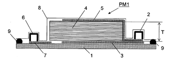
도 1은 종래의 RTM 성형법을 이용한 섬유 강화 플라스틱의 제조 방법을 실시하기 위한 성형형의 종단면 모식도이다.
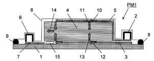
도 2는 도 1의 성형형에서의 수지의 적층체에의 주입, 함침의 모습을 도시하는 모식도이다.
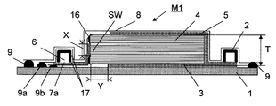
도 3은 본 발명의 RTM 성형법을 이용한 섬유 강화 플라스틱의 제조 방법을 실시하기 위한 성형형의 일례의 종단면 모식도이다.
도 4는 도 3의 성형형에서의 수지의 적층체에의 주입, 함침의 모습을 도시하는 모식도이다.
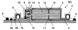
도 5는 본 발명의 RTM 성형법을 이용한 섬유 강화 플라스틱의 제조 방법을 실시하기 위한 성형형의 다른 일례의 종단면 모식도이다.
도 6은 도 5의 성형형에서의 수지의 적층체에의 주입, 함침의 모습을 도시하는 모식도이다.
도 7은 본 발명의 RTM 성형법을 이용한 섬유 강화 플라스틱의 제조 방법을 실시하기 위한 성형형의 다른 일례의 종단면 모식도이다.BRIEF DESCRIPTION OF THE DRAWINGS It is a longitudinal cross-sectional view of the shaping | molding die for implementing the manufacturing method of fiber reinforced plastics using the conventional RTM shaping | molding method.
It is a schematic diagram which shows the state of injection | pouring and impregnation of resin into the laminated body in the shaping | molding die of FIG.
It is a longitudinal cross-sectional view of an example of the shaping | molding die for implementing the manufacturing method of fiber reinforced plastics using the RTM shaping | molding method of this invention.
It is a schematic diagram which shows the state of injection | pouring and impregnation of resin into the laminated body in the shaping | molding die of FIG.
It is a longitudinal cross-sectional view of another example of the shaping | molding die for implementing the manufacturing method of fiber reinforced plastics using the RTM shaping | molding method of this invention.
FIG. 6: is a schematic diagram which shows the state of injection | pouring and impregnation of resin in the shaping | molding die of FIG.
It is a longitudinal cross-sectional view of another example of the shaping | molding die for implementing the manufacturing method of fiber reinforced plastics using the RTM shaping | molding method of this invention.
우선, 도 1 및 도 2를 참조하면서, 종래의 RTM 성형법을 이용한 섬유 강화 플라스틱의 제조 방법을 설명한다.First, referring to FIGS. 1 and 2, a method for producing fiber-reinforced plastic using the conventional RTM molding method will be described.
도 1은 종래의 RTM 성형법을 이용한 섬유 강화 플라스틱의 제조 방법을 실시하기 위한 성형형(PM1)의 종단면 모식도이다. 도 1에 있어서, 성형형(PM1)은 그 기초부에 성형형(PM1)의 하형(1)을 갖는다. 하형(1)의 내면측(도면에서 상면측)에 복수의 강화 섬유 기재가 적층되어 이루어지는 적층체(4)가 위치하고 있다. 도 1에 있어서, 적층체(4)의 우측 단부와 하형(1)의 우측 단부 사이의 위치에 수지 주입구(2)가 형성되고, 도 1에 있어서, 적층체(4)의 좌측 단부와 하형(1)의 좌측 단부 사이의 위치에 수지 흡인구(진공 흡인구)(6)가 형성되어 있다.BRIEF DESCRIPTION OF THE DRAWINGS It is a longitudinal cross-sectional view of the shaping | molding die PM1 for implementing the manufacturing method of the fiber reinforced plastics using the conventional RTM shaping | molding method. In FIG. 1, shaping | molding die PM1 has the lower mold |
하형(1)의 상측에 적층체(4), 수지 주입구(2) 및 수지 흡인구(6)를 덮도록 배깅 필름(8)이 위치하고 있다. 배깅 필름(8)은 성형형(PM1)의 상형에 상당한다.The
하형(1)의 내면과 배깅 필름(상형)(8)의 내면 사이에 성형형(PM1)의 내부 공간이 형성되어 있다. 하형(1) 내면의 주변 단부와 배깅 필름(8) 내면의 주변 단부 사이에 밀봉재(9)가 설치되어 있다. 성형형(PM1)의 내부 공간은 밀봉재(9)에 의해 외부에 대하여 밀폐 공간으로 되어 있다.An internal space of the molding die PM1 is formed between the inner surface of the
성형형(PM1)에 있어서, 하형(1)의 내면(상면)과 적층체(4)의 하면 사이에 수지 주입구(2)에 연결되는 하면측 수지 확산 매체(수지 확산 매체(뒤))(3)가 설치되고, 배깅 필름(8)의 내면과 적층체(4)의 상면 사이에 수지 주입구(2)에 연결되는 상면측 수지 확산 매체(수지 확산 매체(앞))(5)가 설치되어 있다. 또한, 하형(1)의 내면(상면)과 적층체(4)의 하면 사이에 하형(1)의 내면(상면)을 따라 수지 흡인구(6)에 연결되는 수지 흡인 매체(7)가 설치되어 있다.In the shaping | molding die PM1, the lower surface side resin diffusion medium (resin diffusion medium (rear)) connected to the
성형형(PM1)에 있어서, 적층체(4)는 하형(1), 배깅 필름(8) 및 밀봉재(9)에 의해 둘러싸여진 밀폐 공간에 위치한다.In the shaping | molding die PM1, the
성형형(PM1)에서의 적층체(4)에의 수지의 주입은, 성형형(PM1)의 내부 기체가 수지 흡인구(6)를 통하여 진공 펌프 등에 의해 흡인됨으로써, 수지 흡인 매체(7)를 통하여 성형형(PM1)의 내부가 감압 상태로 되고, 이에 따라 수지 주입구(2)로부터 하면측 수지 확산 매체(3) 및 상면측 수지 확산 매체(5)를 거쳐 적층체(4)에 수지가 주입됨으로써 행해진다.Injection of resin into the
도 2는 도 1의 성형형(PM1)에서의 수지의 적층체에의 주입, 함침의 모습을 도시하는 모식도이다. 도 2에 있어서, 주입된 수지는 상면측 수지 확산 매체(5)가 배치되어 있는 개소에서, 화살표(10)로 나타내어진 바와 같이 상면측 수지 확산 매체(5)를 따라 확산되고, 또한 하면측 수지 확산 매체(3)가 배치되어 있는 개소에서, 화살표(12)로 나타내어진 바와 같이 하면측 수지 확산 매체(3)를 따라 확산된다. 확산된 수지는 적층체(4)의 두께 방향, 즉 화살표(11) 및 화살표(13)로 나타내어지는 방향으로 적층체(4)의 상면 및 하면으로부터 적층체(4)의 안쪽으로 함침된다.FIG. 2: is a schematic diagram which shows the injection | pouring and impregnation of resin into the laminated body in shaping | molding die PM1 of FIG. In FIG. 2, the injected resin is diffused along the upper
하면측 수지 확산 매체(3) 또는 상면측 수지 확산 매체(5)가 배치되어 있지 않은 개소, 즉 도 2에 있어서 하형(1)의 상면과 적층체(4)의 하면 사이가 공백으로 나타내어져 있는 개소, 또는 배깅 필름(8)의 내면과 적층체(4)의 상면 사이가 공백으로 나타내어져 있는 개소에서는 수지 확산 매체가 존재하지 않기 때문에, 수지 확산 매체에 의한 적층체(4)로의 수지의 공급이 없다. 그로 인해, 수지 확산 매체가 존재하지 않는 개소에서는, 적층체(4)의 안쪽에 함침된 수지만이 적층체(4)를 형성하고 있는 강화 섬유 기재의 면내 방향으로 함침하게 된다. 도 2에 있어서, 이 상태가 모식적으로 화살표(14)에 의해 나타내어져 있다.Where the lower surface side
그러나, 도 2에 있어서, 적층체(4)의 좌측 단부면과 배깅 필름(8)의 내면 사이의 공백부가 나타낸 바와 같이, 수지 흡인 매체(7)가 적층체(4)의 강화 섬유 기재의 층간, 또는 적층체(4)의 측단의 표면(측면)에 접촉하여 배치되어 있지 않기 때문에, 화살표(15)로 나타내어지는 쇼트 패스에 의한 수지의 유로를 통과하는 수지의 쪽이, 화살표(14)로 나타내어지는 유로를 통과하는 수지보다 단시간에 상형(1)의 내면(상면)을 따라 설치되어 있는 수지 흡인 매체(7)에 도달한다.However, in FIG. 2, as shown by the gap between the left end surface of the
즉, 수지가 하면측 수지 확산 매체(3) 및 상면측 수지 확산 매체(5)가 존재하지 않는 개소에서, 적층체(4)의 두께 방향에 걸쳐 함침 완료하는 것보다 먼저, 수지는 화살표(15)로 나타내어지는 쇼트 패스를 통과하여 수지 흡인 매체(7)에 흡인된다. 그 결과, 적층체(4)의 내부에 수지의 미함침 부분이 발생하는 문제가 있었다.That is, before the impregnation is completed over the thickness direction of the
다음으로, 도 3 및 도 4를 참조하면서, 본 발명의 섬유 강화 플라스틱의 제조 방법을 설명한다.Next, the manufacturing method of the fiber reinforced plastics of this invention is demonstrated, referring FIG. 3 and FIG.
도 3은 본 발명의 RTM 성형법을 이용한 섬유 강화 플라스틱의 제조 방법을 실시하기 위한 성형형의 일례인 성형형(M1)의 종단면 모식도이다. 또한, 도 3에 있어서, 도 1에 도시되어 있는 부재와 공통의 부재에는 동일한 부호가 붙여져 있다.Fig. 3 is a vertical cross-sectional view of a molding die M1 that is an example of a molding die for carrying out a method for producing a fiber-reinforced plastic using the RTM molding method of the present invention. 3, the same code | symbol is attached | subjected to the member common to the member shown in FIG.
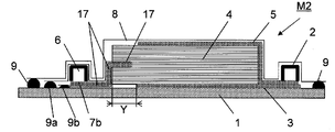
도 3에 있어서, 성형형(M1)은 일단에 수지 주입구(2)를, 타단에 수지 흡인구(진공 흡인구)(6)를 갖는다. 성형형(M1)의 내부 공간에 복수매의 강화 섬유 기재가 적층되어 이루어지는 적층체(4)가 수용되어 있다. 수지 주입구(2)로부터 연장되어, 적층체(4)의 대향하는 양면(도면에서 적층체(4)의 상면과 하면)을 따라 수지 확산 매체(3, 5)가 설치되어 있다. 수지는 수지 주입구(2)로부터 수지 확산 매체(3, 5)를 통하여 적층체(4)의 대향하는 양면에 공급된다.3, the shaping | molding die M1 has the
수지 흡인구(6)로부터 연장되어, 수지 흡인구(6)측의 적층체(4)의 측면을 따라, 이 측면에 접촉하거나 또는 이 측면에 대하여 간격을 두고 적층체(4)로부터의 기체 또는 수지의 흡인이 가능한 상태로 수지 흡인 매체(7a)가 설치되어 있다. 적층체(4)로부터 흡인된 기체 또는 수지는 수지 흡인 매체(7a)를 통하여 수지 흡인구(6)를 향하여 이동한다.Gas from the
성형형(M1)에 있어서, 수지 흡인구(6)로부터 수지 흡인 매체(7a)를 통하여 성형형(M1)의 내부 공간의 기체가 흡인되고, 성형형(M1)의 내부 공간이 감압된 후, 수지 주입구(2)로부터 수지 확산 매체(3, 5)를 통하여 적층체(4)에 수지가 주입되고, 적층체(4)에 주입된 수지의 일부가 수지 흡인 매체(7a)를 통하여 수지 흡인구(6)를 향하여 이동함으로써 적층체(4)에 수지가 함침된다. 적층체(4)에 함침된 수지가 고화함으로써 섬유 강화 플라스틱이 제조된다. 제조된 섬유 강화 플라스틱은 성형형(M1)으로부터 취출되어, 그대로 또는 마무리 가공이 실시된 후, 성형품으로서 사용된다.In the mold M1, after the gas in the internal space of the mold M1 is sucked through the
구체적으로는, 도 3에 있어서, 성형형(M1)은 그 기초부에 성형형(M1)의 하형(1)을 갖는다. 하형(1)의 내면측(도 3에서 상면측)에 복수의 강화 섬유 기재가 적층되어 이루어지는 적층체(4)가 위치하고 있다. 도 3에 있어서, 적층체(4)의 우측 단부와 하형(1)의 우측 단부 사이의 위치에 수지 주입구(2)가 형성되고, 도 3에 있어서 적층체(4)의 좌측 단부와 하형(1)의 좌측 단부 사이의 위치에 수지 흡인구(진공 흡인구)(6)가 형성되어 있다.Specifically, in FIG. 3, the mold M1 has a
하형(1)의 상측에 적층체(4), 수지 주입구(2) 및 수지 흡인구(6)를 덮도록 배깅 필름(8)이 위치하고 있다. 배깅 필름(8)은 성형형(M1)의 상형에 상당한다. 하형(1)의 내면과 배깅 필름(상형)(8)의 내면 사이에 성형형(M1)의 내부 공간이 형성되어 있다. 하형(1) 내면의 주변 단부의 상면과 배깅 필름(8) 내면의 주변 단부 사이에 밀봉재(9)가 설치되어 있다.The
성형형(M1)에 있어서, 하형(1)의 내면(상면)과 적층체(4)의 하면 사이에 수지 주입구(2)에 연결되는 하면측 수지 확산 매체(수지 확산 매체(뒤))(3)가 설치되고, 배깅 필름(8)의 내면과 적층체(4)의 상면 사이에 수지 주입구(2)에 연결되는 상면측 수지 확산 매체(수지 확산 매체(앞))(5)가 설치되어 있다.In the shaping mold M1, the lower surface side resin diffusion medium (resin diffusion medium (rear)) connected to the
또한, 하형(1)의 내면(상면)과 배깅 필름(8)의 내면 사이에 수지 흡인구(6)에 연결되는 수지 흡인 매체(7a)가 설치되어 있다. 수지 흡인 매체(7a)의 수지 흡인구(6)와는 반대측의 단부를 향하는 부분은, 수지 주입구(2)가 위치하는 측의 적층체(4)의 측면(도 3에서의 우측 측면)과는 반대측의 적층체(4)의 측면(도 3에서의 좌측의 측벽(SW)의 표면)을 따라 상측에 연장되고, 적층체(4)의 측면과 배깅 필름(8)의 내면 사이에서, 또한 적층체(4)의 측면의 적어도 일부의 영역에서 적층체(4)로부터 수지의 흡인이 가능한 상태로 적층체(4)의 측면을 마주보고 필요에 따라 적층체(4)의 측면에 접촉하는 상태로 위치하고 있다.Moreover, the
성형형(M1)에 있어서, 적층체(4)는 하형(1), 배깅 필름(8) 및 밀봉부(9)에 의해 둘러싸여진 밀폐 공간에 위치한다.In the shaping | molding die M1, the
성형형(M1)에서의 적층체(4)로의 수지의 주입은, 성형형(M1)의 내부 기체가 수지 흡인구(6)를 통하여 진공 펌프 등에 의해 흡인됨으로써, 수지 흡인 매체(7a)를 통하여 성형형(M1)의 내부가 감압 상태로 되고, 이에 따라 수지 주입구(2)로부터 하면측 수지 확산 매체(3) 및 상면측 수지 확산 매체(5)를 거쳐 적층체(4)에 수지가 주입됨으로써 행해진다.Injection of the resin into the
성형형(M1)에 있어서, 수지 흡인 매체(7a)는, 적층체(4)의 두께 중앙부를 포함하도록 적층체(4)의 두께에 의해 형성되는 측면의 전체 길이에 걸쳐 배치되어 있는 것이 바람직하다. 또한, 수지 흡인 매체(7a)에는 적층체(4)의 두께에 의해 형성되는 측면의 중앙부의 흡인 개소, 즉 도 3에 도시하는 구역(X)의 상하 위치에 밀봉 고정재(16)가 부착되어 있는 것이 바람직하다. 또한, 수지 흡인 매체(7a)는 흡인 개소 이외의 부분의 양면 또는 측면도 포함시켜 기밀 재료(17)에 의해 덮여져 있는 것이 바람직하다.In the shaping | molding die M1, it is preferable that the
밀봉 고정재(16)로서는 점착성 테이프나 실란트와 같은 탄성체의 밀봉을 이용할 수도 있지만, 진공 흡인 후의 형상의 안정성을 높이기 위해서나, 성형 후의 이형성을 고려하여 실리콘 고무를 이용하는 것이 바람직하다.Although sealing of elastic bodies, such as an adhesive tape and a sealant, can be used as the
밀봉 고정재(16)는, 수지 흡인 매체(7a)와 적층체(4)의 두께에 의해 형성되는 측면과의 사이에, 적층체의 두께 중앙부에 대응하는 개소를 밀봉하지 않도록 배치되며, 그 길이는 적층체의 두께와 동일한 길이이며, 또한 밀봉하지 않는 개소를 형성하기 위하여 중앙부에서 높이가 0.1 내지 5mm인 슬릿상의 수지 흡인구가 개방되고, 이 수지 흡인구의 폭은 0.1 내지 50mm인 것이 바람직하다.The
이 상태에서, 수지 주입구(2)로부터 수지가 주입되면, 도 4에 도시한 바와 같이, 수지는 화살표(10, 12)로 나타내어진 바와 같이 하측 수지 확산 매체(3)와 상측 수지 확산 매체(5)로 확산되면서, 화살표(11, 13)로 나타내어진 바와 같이 적층체의 두께 방향으로도 함침하기 시작한다.In this state, when resin is injected from the
도 3에 도시하는 성형형의 양태, 즉 성형형(M1)에 있어서는 수지 흡인 매체(7a)가 적층체의 두께에 의해 형성되는 측면의 중앙부에 배치되어 있기 때문에, 수지 확산 매체(3, 5)를 통하여 적층체(4)의 두께 방향으로 함침된 수지는, 수지 흡인 매체(7a)의 흡인에 의해 화살표(14)로 나타내어지는 방향(면내 방향)으로 함침이 진행되어, 수지 확산 매체(3, 5)가 배치되어 있지 않은 개소(수지 확산 매체 비존재 구역(Y))에 대응하는 위치에서의 적층체(4)의 부분에도 수지를 함침할 수 있어 수지의 미함침부의 발생을 대폭 억제할 수 있다.In the aspect of the shaping | molding die shown in FIG. 3, ie, shaping | molding die M1, since the
적층체를 구성하고 있는 강화 섬유 기재가 동일하고, 적층 구성이 두께 방향에 대하여 대칭이면, 적층체의 두께 방향으로 함침된 수지의 합류(화살표(11, 13)로 나타내어지는 수지의 흐름의 합류)는 적층체(4)의 두께 중앙이 되기 때문에, 수지 흡인 매체(7a)의 수지 흡인이 가능한 개소의 배치는 적층체(4)의 두께 중앙으로 하는 것이 바람직하다.When the reinforcing fiber bases constituting the laminate are the same and the laminate configuration is symmetrical with respect to the thickness direction, confluence of the resins impregnated in the thickness direction of the laminate (confluence of the flow of resin represented by
한편, 예를 들면, 강화 섬유의 종류, 단위 면적당 중량, 직조직이 상이한 등의 복수의 종류의 강화 섬유 기재에 의해 적층체가 구성되어 있고, 적층 구성이 두께 방향에 대하여 대칭이 아닌 경우에는, 수지의 두께 방향으로의 함침 속도는 적층체를 구성하는 각 강화 섬유 기재의 함침성에 의존하기 때문에, 반드시 동일하게는 되지 않아, 결과로서 적층체에 함침한 수지가 합류하는 개소는 반드시 적층체의 두께 중앙이 된다고는 할 수 없다.On the other hand, when a laminated body is comprised by the some kind of reinforcing fiber base material, such as a kind of reinforcing fiber, the weight per unit area, and a woven structure, and a laminated structure is not symmetric with respect to the thickness direction, resin Since the impregnation rate in the thickness direction of the film depends on the impregnation of the respective reinforcing fiber substrates constituting the laminate, it is not necessarily the same, and as a result, the point where the resin impregnated into the laminate joins must be the thickness center of the laminate. This cannot be said.
그로 인해, 이러한 비대칭의 경우에는 수지 흡인 매체(7a)의 수지 흡인이 가능한 개소의 위치 결정은, 적층체로의 수지의 함침 시험 등에 의해 수지의 함침이 합류하는 개소를 미리 확인함으로써 행하면 된다. 또는, 함침 계산 또는 FEM(Finite Element Method)을 이용한 함침 시뮬레이션 등의 해석 결과를 바탕으로 어림한 수지의 합류 개소를 확인하여, 수지가 합류하는 층간을 포함하도록 수지 흡인 매체(7a)의 수지 흡인이 가능한 개소의 위치 결정을 행하면 된다.Therefore, in the case of such an asymmetry, positioning of the location where resin suction of the
또한, 성형형(M1)에 있어서는, 수지 흡인 매체(7a)는 적층체(4)의 흡인 개소 이외의 부분이 기밀 재료(17)로 덮여져 있기 때문에, 수지 확산 매체(3, 5)로부터 주입된 수지가 적층체(4)에 함침되지 않고 수지 흡인 매체(7a)에 흡인되어 버리는 쇼트 패스(화살표(15)로 나타내어지는 쇼트 패스)의 형성을 억제할 수 있어, 적층체(4)에서의 수지의 미함침 부분의 발생을 대폭 억제할 수 있다.Moreover, in the shaping | molding die M1, since the
수지 흡인 매체(7a)의 배깅 필름(8)의 내면측에 위치하는 표면에 설치된 기밀 재료는, 수지 흡인 매체(7a)를 따라 수지 흡인구(6)의 방향으로 연장되어 수지 흡인구(6)를 덮어 하형의 단부에 이르도록 위치하고, 이 기밀 재료의 하면의 주단부와 하형(1)의 상면의 종단부 사이에 밀봉재(9a)가 설치되어, 이 기밀 재료와 하형(1)의 사이가 기밀하게 되어 있다.The airtight material provided on the surface located in the inner surface side of the
또한, 수지 흡인 매체(7a)의 배깅 필름(8)의 내면측에 위치하는 표면의 반대측의 표면에 설치된 기밀 재료는, 수지 흡인 매체(7a)를 따라 수지 흡인구(6)의 방향으로 연장되어 수지 흡인구(6)의 하측을 통과하여 하형(1)의 단부에 이르도록 위치하고, 이 기밀 재료의 하면의 주단부와 하형의 상면의 종단부 사이에 밀봉재(9b)가 설치되어, 이 기밀 재료와 하형(1)의 사이가 기밀하게 되어 있다.Moreover, the airtight material provided in the surface on the opposite side to the surface located in the inner surface side of the
이에 의해, 수지 흡인구(6)에 위치하는 수지 흡인 매체(7a)의 상면은, 수지 흡인구(6)에 대하여 기체 또는 수지가 유통 가능하게 개방되고, 수지 흡인구(6)에 위치하는 수지 흡인 매체(7a)의 하면은, 기밀 재료에 의해 외부와의 기체 또는 수지의 유통이 불가능한 구조로 되어 있다.Thereby, the upper surface of the
또한, 성형형(M1)에 있어서는, 상술한 바와 같이 수지 확산 매체가 배치되어 있는 개소에서의 적층체의 두께 방향의 수지의 함침이 완료되었다고 하여도, 수지 확산 매체 비존재 구역(Y)의 부분에 수지가 함침되어 있지 않으면, 수지 흡인 매체(7a)로부터 수지는 바로 흡인되지 않는다.In addition, in the shaping | molding die M1, even if the impregnation of resin of the thickness direction of the laminated body in the location where the resin diffusion medium is arrange | positioned as mentioned above is completed, the part of the resin diffusion medium non-existence area Y is completed. If the resin is not impregnated with the resin, the resin is not directly sucked from the
특히, 수지 주입, 함침 중에 적층체에서 상정 외의 수지의 미함침부가 발생한 경우라도, 수지 확산 매체 비존재 구역(Y)에 의해 수지가 흡인될 때까지 충분한 시간을 확보할 수 있기 때문에, 미함침부에 수지가 함침한 후에 있어서 수지 흡인 매체(7a)에 의해 수지를 흡인할 수 있다.In particular, even when an unimpregnated portion of an unexpected resin occurs in the laminate during resin injection and impregnation, sufficient time can be ensured until the resin is attracted by the resin diffusion medium non-existing zone (Y). After the resin is impregnated with the resin, the resin can be sucked by the
즉, 적층체의 내부에서, 강화 섬유 기재의 두께 방향의 함침성이나 두께 등의 품질의 변동에 의해 수지의 두께 방향의 함침 시간에 변동이 생겨, 반드시 적층체의 수지 주입구(2)의 측으로부터 순차적으로 함침이 완료되어 간다고는 할 수 없다. 그로 인해, 적층체의 내부에 수지의 미함침부를 남긴 상태로 수지가 수지 흡인 매체(7a)에 도달하여 흡인되어 버리는 경우도 발생할 수 있다.That is, in the inside of a laminated body, fluctuation | variation arises in the impregnation time of the resin thickness direction by fluctuation | variation in quality, such as the impregnability of the thickness direction of a reinforcement fiber base material, thickness, etc., and is necessarily from the side of the
여기서, 수지 확산 매체 비존재 구역(Y)을 설치함으로써, 수지는 수지 확산 매체(3, 5)로부터 적층체의 두께 방향으로 함침하여 합류한 후, 면내 방향으로 수지 확산 매체 비존재 구역(Y)의 길이만큼 함침한 후에, 수지 흡인 매체(7a)에 의해 흡인된다. 그로 인해, 상정 외에 수지가 합류한 후에, 적층체의 내부에 수지의 미함침부가 발생한 경우라도 수지가 합류한 후에 수지 흡인 매체(7a)에 도달할 때까지의 시간을 이용하여 수지의 미함침부의 수지의 함침을 완료시킬 수 있다.Here, by providing the resin diffusion medium non-existing zone Y, the resin is impregnated and joined in the thickness direction of the laminate from the
다음으로, 도 5 및 도 6을 참조하면서, 도 3에 도시된 성형형(M1)과는 별도의 양태인 성형형(M2)이 이용되는 본 발명의 섬유 강화 플라스틱의 제조 방법을 설명한다. 또한, 도 5에 있어서, 도 3에 도시되어 있는 부재와 공통의 부재에는 동일한 부호가 붙여져 있다.Next, with reference to FIG. 5 and FIG. 6, the manufacturing method of the fiber reinforced plastics of this invention in which the shaping | molding die M2 which is another aspect from the shaping | molding die M1 shown in FIG. 3 is used is demonstrated. 5, the same code | symbol is attached | subjected to the member common to the member shown in FIG.
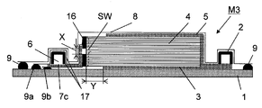
도 5는 본 발명의 RTM 성형법을 이용한 섬유 강화 플라스틱의 제조 방법을 실시하기 위한 성형형의 다른 일례의 성형형(M2)의 종단면 모식도이다. 도 5에 도시되는 성형형(M2)과 도 3에 도시되는 성형형(M1)의 차이는, 적층체(4)의 수지 흡인구(6)가 위치하는 측의 측면을 따라 설치되어 있는 수지 흡인 매체의 배치에 있다.FIG. 5: is a longitudinal cross-sectional view of the shaping | molding die M2 of another example of a shaping | molding die for implementing the manufacturing method of fiber reinforced plastics using the RTM shaping | molding method of this invention. The difference between the mold M2 shown in FIG. 5 and the mold M1 shown in FIG. 3 is resin suction provided along the side surface at which the
즉, 성형형(M2)에 있어서는, 적층체(4)의 측면을 따라 상측으로 연장되어 있는 수지 흡인 매체(7b)의 선단부가, 적층체(4)의 측면으로부터 절곡되어 적층체의 강화 섬유 기재의 층간에 삽입되어 있다. 이 점에 있어서 성형형(M2)과 성형형(M1)에서의 수지 흡인 매체의 배치 방법이 상이하다.That is, in the shaping | molding die M2, the front-end | tip part of the
수지 흡인 매체(7b)가 이와 같이 배치되어 있는 성형형(M2)에 있어서, 수지 주입구(2)로부터 수지가 주입되면, 도 6에 도시된 바와 같이, 수지는 화살표(10, 12)로 나타내어진 바와 같이 하면측 수지 확산 매체(수지 확산 매체(뒤))(3)와 상면측 수지 확산 매체(수지 확산 매체(앞))(5)로 확산되면서, 화살표(11, 13)로 나타내어진 바와 같이 적층체(4)의 두께 방향으로도 함침하기 시작한다.In the molding mold M2 in which the
성형형(M2)에 있어서는, 수지 흡인 매체(7b)의 수지 흡인구(6)측과는 반대측의 선단부가 적층체(4)의 강화 섬유 기재의 층간에 삽입되어 있기 때문에, 수지 확산 매체(3, 5)를 통하여 적층체(4)의 두께 방향으로 함침된 수지는, 수지 흡인 매체(7b)에 의해 화살표(14)로 나타내어지는 방향으로 함침되면서 이동하여 수지 확산 매체(3, 5)가 배치되어 있지 않은 개소, 즉 수지 확산 매체 비존재 구역(Y)에 대응하는 위치에 있는 적층체의 부분에도 함침할 수 있어 수지의 미함침부의 발생을 대폭 억제할 수 있다.In the shaping | molding die M2, since the front-end | tip part on the opposite side to the
또한, 도 5의 성형형(M2)에서의 수지 확산 매체 비존재 구역(Y)은, 도 3의 성형형(M1)에서의 수지 확산 매체 비존재 구역(Y)과 동일한 기능을 갖는다. 그로 인해, 수지 흡인 매체(7b)가 강화 섬유 기재의 층간에 삽입되어 있지 않은 개소에서도 수지가 적층체에 완전히 함침하기 위하여 필요한 시간을 거친 후, 수지 흡인 매체(7b)로부터 수지가 흡인된다. 수지 주입, 함침 중에 상정 외의 수지의 미함침이 발생한 경우에도 수지 확산 매체 비존재 구역(Y)이 설치되어 있음으로써, 수지가 흡인될 때까지의 충분한 시간을 확보할 수 있기 때문에, 이 시간으로 수지의 미함침부에도 수지의 함침이 널리 퍼져 수지의 함침이 완료된 후, 수지는 수지 흡인 매체(7b)를 통하여 수지 흡인구(6)를 향하여 흡인된다.In addition, the resin-diffusion medium non-existing zone Y in the shaping | molding die M2 of FIG. 5 has the same function as the resin-diffusion medium non-existing zone Y in the shaping | molding die M1 of FIG. Therefore, even after the
또한, 수지 흡인 매체(7b)는 적층체(4)로부터의 기체 또는 수지의 흡인을 행하지 않는 개소가 기밀 재료(17)로 덮여져 있다. 이에 의해, 수지 확산 매체(3, 5)로부터 주입된 수지가 적층체(4)에 함침되지 않고, 수지 흡인 매체(7b)에 흡인되어 버리는 화살표(15)로 나타내어지는 쇼트 패스의 형성이 억제된다. 이 기밀 재료(17)에 의해서도 수지의 미함침 개소의 발생을 대폭 억제할 수 있다.The
기밀 재료(17)는 기체의 기밀을 유지할 수 있는 재료이면 특별히 한정되는 것이 아니며, 그 중에서도 배깅 필름과 동일한 재질의 것을 이용하는 것이 바람직하다. 도 5에 도시된 바와 같이, 기밀 재료(17)가 수지 흡인 매체(7b)의 상면에 배치되고, 수지 흡인구(수지 흡인구)(6)를 덮어 밀봉재(9a)로 하형(1)과의 사이를 밀착함으로써, 상정 외에 상측 수지 확산 매체(5)로부터 확산된 수지가, 도 6에 있어서 화살표(15)로 나타내어진 바와 같은 쇼트 패스를 형성하였다고 하여도, 수지는 수지 흡인 매체(7b)에 의해 직접 흡인되지 않는다. 수지는 적층체(4)의 두께 방향으로 함침한 후에 수지 흡인 매체(7b)에 의해 비로소 흡인되기 때문에, 적층체(4)의 수지의 함침성을 향상시킬 수 있다.The
마찬가지로, 기밀 재료(17)가 수지 흡인 매체(7b)의 하면에 배치되고, 밀봉재(9b)로 하형(1)과의 사이를 밀착함으로써, 상정 외에 하측 수지 확산 매체(3)로부터 확산된 수지가, 도 6에 있어서 화살표(15)로 나타내어진 바와 같은 쇼트 패스를 형성하였다고 하여도, 수지는 수지 흡인 매체(7b)에 의해 직접 흡인되지 않는다. 수지는 적층체(4)의 두께 방향으로 함침한 후에 수지 흡인 매체(7b)에 의해 비로소 흡인되기 때문에, 적층체(4)의 수지의 함침성을 향상시킬 수 있다.Similarly, the
도 5에 도시하는 성형형(M2)을 이용한 섬유 강화 플라스틱의 제조 방법은, 수지 경화 후에 수지 흡인 매체(7b)의 일부가 수지가 경화한 적층체의 내부에 남아 버리기 때문에, 적층체 전체를 섬유 강화 플라스틱의 제품으로서 사용하는 것은 불가능하다. 그러나, 도 5에 도시하는 성형형(M2)을 이용한 섬유 강화 플라스틱의 제조 방법은, 도 3에 도시하는 성형형(M1)을 이용한 섬유 강화 플라스틱의 제조 방법보다 적층체를 성형형의 내부 공간에 수납할 때, 간단히 수지 흡인 매체(7b)를 적층체의 측면에 배치할 수 있기 때문에, 제조 사이클 시간을 단축할 수 있는 등의 이점을 갖는 양태이다.In the manufacturing method of the fiber reinforced plastic using the shaping | molding die M2 shown in FIG. 5, since a part of
실시예 1Example 1
강화 섬유 기재로서 탄소 섬유(도레이 가부시끼가이샤 제조 탄소 섬유: T620SC-24000)가 일방향으로 배열된, 탄소 섬유의 단위 면적당 중량이 600g/m2인 탄소 섬유 기재를 사용하였다. 이 탄소 섬유 기재를 일방향으로 정렬시켜 50매를 적층한 적층체를 준비하였다.As the reinforcing fiber base material, a carbon fiber base material having a weight per unit area of carbon fiber of 600 g / m 2 in which carbon fiber (carbon fiber manufactured by Toray Industries, Ltd .: T620SC-24000) was arranged in one direction was used. The carbon fiber base material was aligned in one direction, and the laminated body which laminated | stacked 50 sheets was prepared.
이 적층체를 도 3에 도시한 바와 같이 성형형(M1)의 하형(1) 상에 배치하였다.This laminated body was arrange | positioned on the lower mold |
상면측 수지 확산 매체(5) 및 하면측 수지 확산 매체(3), 수지 흡인 매체(7a)는 전부 동일한 폴리프로필렌제 메쉬이며, 메쉬의 각 공극의 형상이 한변이 2.5mm, 두께가 약 0.6mm인 것을 사용하였다.The upper surface
상면측 수지 확산 매체(3)와 하면측 수지 확산 매체(5)는, 도 3에 도시하는 수지 확산 매체 비존재 구역(Y)의 적층체(4)의 길이 방향에서의 길이가 모두 10mm가 되도록 배치하였다.The upper surface side
수지 흡인 매체(7a)는, 도 3에 도시된 바와 같이, 적층체(4)의 두께가 형성하는 측면(측벽(SW))의 두께 방향의 중앙 개소에 접촉하도록 적층체(4)의 두께가 형성하는 측면의 전체 길이에 걸쳐 배치되었다. 수지 흡인 매체(7a)에, 이 중앙개소를 사이에 끼운 상하의 위치에 밀봉 고정재(16)를 배치하고, 적층체(4)의 두께가 형성하는 측면에 직접 접촉하는 구역(X)이 5mm가 되도록 배치하였다.As shown in FIG. 3, the
또한, 도 3에 도시된 바와 같이, 기밀 재료(17)를 수지 흡인 매체(7a)의 양면에 배치하고, 성형형(M1)의 하형(1)과의 사이에서 밀봉재(9a, 9b)를 이용하여 밀폐하였다. 기밀 재료(17)로서는 두께 약 50㎛의 폴리아미드제 배깅 필름을 사용하였다.3, the
또한, 수지 주입구(2), 수지 흡인구(진공 흡인구)(6)로서 폭과 높이가 각각 15mm인 알루미늄제 채널을 사용하였다. 도 3에 도시된 바와 같이, 수지 주입구(2)를 상면측 수지 확산 매체(5) 및 하면측 수지 확산 매체(3) 상에 배치하고, 수지 흡인구(진공 흡인구)(6)를 수지 흡인 매체(7a) 상에 배치하였다. 그 후, 외경 12mm, 내경 9mm의 폴리아미드제 튜브(도시하지 않음)를 수지 주입구(2), 수지 흡인구(6)에 삽입하였다.As the
또한, 그 위에서 전체를 배깅 필름(8)으로 덮어 성형형(M1)의 하형(1)과의 사이에서 밀봉재(9)를 이용하여 밀폐하였다. 밀봉재(9)와 밀봉 고정재(16)는 동일한 밀봉재를 이용하였다.Moreover, the whole was covered with the
수지 주입구(2)에 삽입한 폴리아미드제 튜브를 폐쇄한 상태로, 수지 흡인구(진공 흡인구)(6)에 삽입한 폴리아미드제 튜브를 진공 펌프(도시하지 않음)에 연결하여, 배깅 필름(8)으로 밀폐한 성형형(M1)의 내부 공간을 진공 흡인함으로써 감압하였다. 이 상태에서의 적층체(4)의 두께(T)는 약 30mm이었다.With the polyamide tube inserted in the
배깅 필름(8)의 내부를 진공 흡인에 의해 감압한 상태에서, 액상의 에폭시 수지를 대기압을 이용하여 수지 주입구(2)에 삽입한 폴리아미드제 튜브를 통하여 주입하고, 상면측 수지 확산 매체(5), 하면측 수지 확산 매체(3)를 이용하여 수지를 적층체(4)에 확산, 함침시켰다.In the state where the inside of the
에폭시 수지는 주요제와 경화제의 2액 혼합의 수지이며, 수지의 점도는 초기 점도가 약 160mPas, 60분 후에 약 2배로 증점하는 경향을 갖는 것이었다.The epoxy resin was a resin of a two-liquid mixture of a main agent and a curing agent, and the viscosity of the resin had an initial viscosity of about 160 mPas and a tendency to thicken about twice after 60 minutes.
이 결과, 적층체(4)에 함침된 수지는 주입 개시로부터 약 20분 후에 수지 흡인 매체(7a)에 배어 나오는 것이 관찰되었다. 이 수지의 배어 나옴에 의해 수지의 적층체(4)로의 함침은 완료되었다고 판단하고, 수지 흡인구(진공 흡인구)(6)를 폐쇄하여 진공 흡인을 중지한 후, 수지 주입구(2)를 폐쇄하여 수지의 주입을 중지하였다.As a result, it was observed that the resin impregnated into the
수지가 함침된 적층체(4)는, 수지 주입구(2)와 수지 흡인구(진공 흡인구)(6)를 폐쇄한 상태로 실온에서 24시간 및 오븐을 이용하여 60℃에서 15시간의 가열을 행하여 수지를 경화시켰다. 수지의 경화가 완료된 후, 성형형(M1) 내에 성형된 성형체를 성형형(M1)으로부터 탈형하였다.The resin-impregnated
제조된 섬유 강화 플라스틱의 성형체를 폭 방향의 중앙에서 전체 길이에 걸쳐 절단하여 절단면을 관찰한 결과, 수지의 미함침 부분이 존재하지 않는 것이 확인되었다.As a result of observing the cut surface by cutting the molded article of the manufactured fiber-reinforced plastic over the entire length at the center in the width direction, it was confirmed that the unimpregnated portion of the resin did not exist.
실시예 2Example 2
도 7은 본 발명의 RTM 성형법을 이용한 섬유 강화 플라스틱의 제조 방법을 실시하기 위한 성형형의 다른 일례의 성형형(M3)의 종단면 모식도이다.FIG. 7: is a longitudinal cross-sectional view of the shaping | molding die M3 of another example of a shaping | molding die for implementing the manufacturing method of fiber reinforced plastics using the RTM shaping | molding method of this invention.
도 7에 도시되는 성형형(M3)과 도 3에 도시되는 성형형(M1)의 상위점은, 후자의 성형형(M1)에서의 밀봉 고정재(16)가 전자의 성형형(M3)에 있어서는 적층체의 측면의 전체면에 부착되어, 밀봉 고정재(16)의 상하 방향의 중앙 부분에 개구(창)가 형성되고, 또한 양면에 기밀 재료를 갖는 수지 흡인 매체(7c)가 밀봉 고정재(16)의 적층체(4)의 측면에 접하고 있는 표면과 반대측의 표면(외표면)을 따라 설치되어 있는 점이다.The difference between the mold M3 shown in FIG. 7 and the mold M1 shown in FIG. 3 is that the
수지 흡인 매체(7c)는 그 양면이 기밀 재료(17)로 덮여져 있지만, 밀봉 고정재(16)의 개구(창) 부분을 마주보는 개소에서 기밀 재료(17)는 마찬가지의 개구(창)를 갖고 있다. 밀봉 고정재(16)의 개구(창)와 기밀 재료(17)의 개구(창)를 통하여 적층체(4)에 함침한 수지가 수지 흡인 매체(7c)로 흡인된다.Both sides of the
도 7에 도시되는 성형형(M3)을 이용하여, 실시예 1과 마찬가지로 하여 섬유 강화 플라스틱의 성형체를 제조하였다.A molded article of a fiber-reinforced plastic was produced in the same manner as in Example 1 using the molding die M3 shown in FIG. 7.
제조된 성형체를 실시예 1의 경우와 마찬가지로 절단하여 절단면을 관찰한 결과, 성형체에 수지의 미함침 부분이 없는 것이 확인되었다.The produced molded product was cut in the same manner as in Example 1 and the cut surface was observed, and it was confirmed that the molded product had no unimpregnated portion of the resin.
비교예 1Comparative Example 1
도 1에 도시되는 성형형(PM1)을 이용하여, 실시예 1과 마찬가지로 하여 섬유 강화 플라스틱의 성형체를 제조하였다.Using the shaping | molding die PM1 shown in FIG. 1, the molded object of fiber reinforced plastics was manufactured like Example 1.
제조된 성형체를 실시예 1의 경우와 마찬가지로 절단하여 절단면을 관찰한 결과, 적층체(4)의 두께 방향의 중앙으로부터 하측 수지 확산 매체(3)를 마주보고 있었던 적층체(4)의 하면에 가까운 위치까지의 광범위하게 수지의 미함침 부분이 존재하고 있는 것이 확인되었다.The produced molded body was cut in the same manner as in Example 1, and the cut surface was observed. It was confirmed that the unimpregnated part of resin exists to the position extensively.
1: 성형형의 하형
2: 수지 주입구
3: 하면측 수지 확산 매체(수지 확산 매체(뒤))
5: 상면측 수지 확산 매체(수지 확산 매체(앞))
4: 적층체
6: 수지 흡인구(진공 흡인구)
7, 7a, 7b, 7c: 수지 흡인 매체
8: 배깅 필름
9, 9a, 9b: 밀봉재
10, 11, 12, 13, 14, 15: 화살표
16: 밀봉 고정재
17: 기밀 재료
M1, M2, M3: 성형형
PM1: 성형형
SW: 수지 주입구와 반대측에 위치하는 적층체의 두께에 의해 형성되는 측벽
X: 수지 흡인 매체의 적층체의 두께가 형성하는 측벽(측면)에 직접 접촉하는 부분(구역)
Y: 수지 확산 매체 비존재 구역1: lower mold
2: resin inlet
3: Lower surface resin diffusion medium (resin diffusion medium (back))
5: Resin Diffusion Medium (Resin Diffusion Medium (front))
4:
6: resin suction port (vacuum suction port)
7, 7a, 7b, 7c: resin suction medium
8: bagging film
9, 9a, 9b: sealing material
10, 11, 12, 13, 14, 15: arrow
16: sealing fixture
17: Airtight Materials
M1, M2, M3: Molded
PM1: Molding Type
SW: side wall formed by the thickness of the laminated body located on the opposite side to the resin injection opening
X: part (zone) which directly contacts the side wall (side surface) which the thickness of the laminated body of a resin suction medium forms.
Y: resin diffusion medium non-existence zone
Claims (13)
(b) 상기 성형형의 내부 공간에 복수매의 강화 섬유 기재가 적층되어 이루어지는 적층체가 수용되고,
(c) 상기 수지 주입구로부터 연장되어 상기 적층체의 대향하는 양쪽 표면을 따라 설치되며, 상기 수지 주입구로부터 상기 적층체의 대향하는 양쪽 표면에 수지를 공급하는 수지 확산 매체와,
(d) 상기 수지 흡인구로부터 연장되어 이 수지 흡인구측의 상기 적층체의 측면을 따라 이 측면에 접촉하거나 또는 이 측면에 대하여 간격을 두고 상기 적층체로부터의 기체 또는 수지의 흡인이 가능한 상태로 설치되며, 상기 적층체로부터 기체 또는 수지를 상기 수지 흡인구를 향하여 이동시키는 수지 흡인 매체가 이용되고,
(e) 상기 수지 흡인구로부터 상기 수지 흡인 매체를 통하여 상기 성형형의 내부 공간의 기체가 흡인되어 상기 성형형의 내부 공간이 감압된 후,
(f) 상기 수지 주입구로부터 상기 수지 확산 매체를 통하여 상기 적층체에 수지가 주입되고,
(g) 상기 적층체에 주입된 수지의 일부가, 상기 수지 흡인 매체를 통하여 상기 수지 흡인구를 향하여 이동함으로써, 상기 적층체에 수지가 함침되어 이루어지는 섬유 강화 플라스틱의 제조 방법.(a) a molding die having a resin injection port at one end and a resin suction port at the other end is used,
(b) a laminate obtained by laminating a plurality of reinforcing fiber substrates in an inner space of the molding die, and
(c) a resin diffusion medium which extends from the resin inlet and is provided along both opposing surfaces of the laminate, and supplies resin to both opposing surfaces of the laminate from the resin inlet;
(d) extends from the resin suction port and in contact with this side along the side of the laminate on the side of the resin suction port or in a state where suction of the gas or resin from the laminate is possible at intervals with respect to the side; A resin suction medium which is provided and moves gas or resin from the laminate toward the resin suction port,
(e) after the gas in the internal space of the molding die is sucked from the resin suction port through the resin suction medium to reduce the internal space of the molding die,
(f) resin is injected into the laminate from the resin inlet through the resin diffusion medium,
(g) A method for producing a fiber-reinforced plastic, in which resin is impregnated into the laminate by moving a portion of the resin injected into the laminate toward the resin suction port through the resin suction medium.
Applications Claiming Priority (5)
| Application Number | Priority Date | Filing Date | Title |
|---|---|---|---|
| JPJP-P-2010-213245 | 2010-09-24 | ||
| JP2010213245 | 2010-09-24 | ||
| JPJP-P-2011-047459 | 2011-03-04 | ||
| JP2011047459A JP5533743B2 (en) | 2010-09-24 | 2011-03-04 | Manufacturing method of fiber reinforced plastic |
| PCT/JP2011/071426 WO2012039409A1 (en) | 2010-09-24 | 2011-09-21 | Method for producing fiber-reinforced plastic |
Publications (1)
| Publication Number | Publication Date |
|---|---|
| KR20130111552A true KR20130111552A (en) | 2013-10-10 |
Family
ID=45873893
Family Applications (1)
| Application Number | Title | Priority Date | Filing Date |
|---|---|---|---|
| KR1020137009107A KR20130111552A (en) | 2010-09-24 | 2011-09-21 | Method for producing fiber-reinforced plastic |
Country Status (9)
| Country | Link |
|---|---|
| US (1) | US9205602B2 (en) |
| EP (1) | EP2620265A4 (en) |
| JP (1) | JP5533743B2 (en) |
| KR (1) | KR20130111552A (en) |
| CN (1) | CN103097099A (en) |
| BR (1) | BR112013005859A2 (en) |
| CA (1) | CA2810699A1 (en) |
| RU (1) | RU2013118703A (en) |
| WO (1) | WO2012039409A1 (en) |
Families Citing this family (21)
| Publication number | Priority date | Publication date | Assignee | Title |
|---|---|---|---|---|
| TWI620843B (en) | 2012-04-18 | 2018-04-11 | 三菱化學股份有限公司 | Carbon fiber bundle,method of manufacturing carbon fiber bundle and resin composite material |
| EP2700492B1 (en) * | 2012-08-23 | 2017-02-01 | Airbus Operations GmbH | Infusion method and structure for infusion method |
| EP2762297B1 (en) * | 2013-02-05 | 2018-10-03 | Siemens Aktiengesellschaft | Pressure sensitive flow distribution medium for VARTM |
| US20150099103A1 (en) * | 2013-10-04 | 2015-04-09 | Rohr, Inc. | Variable matrix composite |
| US9738011B2 (en) * | 2014-05-20 | 2017-08-22 | The Boeing Company | Concurrent infusion of dissimilar resins |
| CN104441687A (en) * | 2014-09-17 | 2015-03-25 | 重庆海电风能集团有限公司 | RTM manufacture process of wind power cabin cover |
| CN106142593B (en) * | 2015-04-10 | 2019-11-26 | 科思创德国股份有限公司 | The method for manufacturing article of fiber reinforced plastics |
| JP6607553B2 (en) * | 2015-05-28 | 2019-11-20 | 三菱航空機株式会社 | Seal structure in VaRTM method |
| JP6537921B2 (en) * | 2015-08-06 | 2019-07-03 | 三菱重工業株式会社 | Apparatus for producing fiber-reinforced plastic, movable base, method for producing shaped fiber substrate, and method for producing fiber-reinforced plastic |
| AU2016203289B2 (en) * | 2016-05-20 | 2022-04-07 | The Boeing Company | A method and system for resin infusing a composite preform |
| MA45359A (en) | 2016-06-14 | 2019-04-17 | Lm Wp Patent Holding As | WIND TURBINE BLADE MANUFACTURING PROCESS |
| US11040502B2 (en) * | 2016-08-09 | 2021-06-22 | Mitsubishi Heavy Industries, Ltd. | Method for producing fiber-reinforced resin molded articles |
| JP6604322B2 (en) * | 2016-12-28 | 2019-11-13 | トヨタ自動車株式会社 | Method for producing fiber-reinforced resin molded body |
| US10786957B2 (en) * | 2017-01-30 | 2020-09-29 | General Electric Company | System, method, and apparatus for infusing a composite structure |
| JP7085803B2 (en) * | 2017-04-28 | 2022-06-17 | 三菱重工業株式会社 | Composite material molding method and composite material molding equipment |
| US11225942B2 (en) | 2017-07-05 | 2022-01-18 | General Electric Company | Enhanced through-thickness resin infusion for a wind turbine composite laminate |
| US10730236B2 (en) * | 2017-08-02 | 2020-08-04 | Ethicon Llc | System and method for additive manufacture of medical devices |
| DE102017128501A1 (en) | 2017-11-30 | 2019-06-06 | Airbus Operations Gmbh | Method for producing a composite component |
| DE102019114329A1 (en) * | 2019-05-28 | 2020-12-03 | Airbus Operations Gmbh | Structure and method for manufacturing components from a plastic or composite material, in particular for aircraft and space vehicles, and auxiliary tools |
| WO2021186659A1 (en) * | 2020-03-19 | 2021-09-23 | 三菱重工業株式会社 | Method for molding composite material and apparatus for molding composite material |
| CN114454381B (en) * | 2022-02-17 | 2023-02-21 | 浙江金凤凰电力科技有限公司 | Gum dipping device suitable for producing oversized core body by adopting integral pultrusion process |
Family Cites Families (20)
| Publication number | Priority date | Publication date | Assignee | Title |
|---|---|---|---|---|
| US4548859A (en) * | 1984-10-12 | 1985-10-22 | The Boeing Company | Breather material and method of coating fabric with silicone rubber |
| US4622091A (en) * | 1984-11-29 | 1986-11-11 | The Boeing Company | Resin film infusion process and apparatus |
| EP0525263B1 (en) * | 1991-08-01 | 1996-03-27 | Scrimp Systems, L.L.C. | Vacuum-forming method and apparatus for vacuum-forming fibre reinforced resin composites |
| US5433165A (en) * | 1994-03-30 | 1995-07-18 | Outboard Marine Corporation | Method of manufacturing a boat hull |
| GB9916157D0 (en) * | 1999-07-10 | 1999-09-08 | British Aerospace | Method for manufacturing a filled hollow fibre composite mate rial |
| US6818159B2 (en) * | 2000-03-17 | 2004-11-16 | Deutsches Zentrum Fuer Luft-Und Raumfahrt E.V. | Process for the production of a composite consisting of a fiber reinforced material |
| DE10140166B4 (en) * | 2001-08-22 | 2009-09-03 | Eads Deutschland Gmbh | Method and device for producing fiber-reinforced components by means of an injection method |
| WO2003101708A1 (en) * | 2002-05-29 | 2003-12-11 | The Boeing Company | Controlled atmospheric pressure resin infusion process |
| JP4104422B2 (en) * | 2002-10-09 | 2008-06-18 | 東レ株式会社 | RTM molding method |
| ES2727872T3 (en) * | 2002-10-09 | 2019-10-21 | Toray Industries | RTM Molding Method |
| JP4542588B2 (en) | 2002-10-09 | 2010-09-15 | 東レ株式会社 | RTM molding method |
| JP4365660B2 (en) | 2002-11-27 | 2009-11-18 | 三菱重工業株式会社 | Manufacturing method of fiber reinforced resin structure and manufacturing apparatus thereof |
| JP4432563B2 (en) * | 2004-03-23 | 2010-03-17 | 東レ株式会社 | Manufacturing method of FRP |
| GB0417634D0 (en) * | 2004-08-09 | 2004-09-08 | Structural Polymer Systems Ltd | Mould |
| JP2006130733A (en) * | 2004-11-04 | 2006-05-25 | Yokohama Rubber Co Ltd:The | Manufacturing method of fiber reinforced resin molded product |
| JP2007176163A (en) | 2005-11-30 | 2007-07-12 | Toray Ind Inc | Manufacturing process of fiber-reinforced plastic |
| US8236410B2 (en) * | 2006-02-28 | 2012-08-07 | Toray Industries, Inc. | Reinforcing fiber base material for preforms, process for the production of laminates thereof, and so on |
| GB0702781D0 (en) * | 2007-02-13 | 2007-03-21 | Airbus Uk Ltd | Method of processing a composite material |
| AU2008227492B2 (en) * | 2007-03-20 | 2013-02-14 | Mitsubishi Heavy Industries, Ltd. | Method of vacuum-assisted RTM |
| JP5223505B2 (en) * | 2007-07-24 | 2013-06-26 | 東レ株式会社 | Manufacturing method of FRP |
-
2011
- 2011-03-04 JP JP2011047459A patent/JP5533743B2/en not_active Expired - Fee Related
- 2011-09-21 CN CN2011800428381A patent/CN103097099A/en active Pending
- 2011-09-21 KR KR1020137009107A patent/KR20130111552A/en not_active Application Discontinuation
- 2011-09-21 WO PCT/JP2011/071426 patent/WO2012039409A1/en active Application Filing
- 2011-09-21 RU RU2013118703/05A patent/RU2013118703A/en not_active Application Discontinuation
- 2011-09-21 BR BR112013005859A patent/BR112013005859A2/en not_active Application Discontinuation
- 2011-09-21 EP EP11826854.9A patent/EP2620265A4/en not_active Withdrawn
- 2011-09-21 CA CA2810699A patent/CA2810699A1/en not_active Abandoned
- 2011-09-21 US US13/825,359 patent/US9205602B2/en not_active Expired - Fee Related
Also Published As
| Publication number | Publication date |
|---|---|
| JP2012086547A (en) | 2012-05-10 |
| JP5533743B2 (en) | 2014-06-25 |
| CN103097099A (en) | 2013-05-08 |
| CA2810699A1 (en) | 2012-03-29 |
| RU2013118703A (en) | 2014-10-27 |
| US9205602B2 (en) | 2015-12-08 |
| WO2012039409A1 (en) | 2012-03-29 |
| EP2620265A4 (en) | 2016-12-28 |
| BR112013005859A2 (en) | 2016-05-17 |
| EP2620265A1 (en) | 2013-07-31 |
| US20130175740A1 (en) | 2013-07-11 |
Similar Documents
| Publication | Publication Date | Title |
|---|---|---|
| KR20130111552A (en) | Method for producing fiber-reinforced plastic | |
| US10183450B2 (en) | Method for impregnation of a fibrous preform and device for implementation of the said method | |
| EP2682247B1 (en) | Rtm molding device, rtm molding method, and semi-molded body | |
| US7866969B2 (en) | Manufacture of composites by a flexible injection process using a double or multiple cavity mold | |
| US8420002B2 (en) | Method of RTM molding | |
| EP1595688B1 (en) | Molded laminate and manufacturing method thereof | |
| JP5476916B2 (en) | Manufacturing method of fiber reinforced plastic | |
| WO2018030470A1 (en) | Method for producing fiber-reinforced resin molded articles | |
| JP2004181627A (en) | Resin transfer molding method | |
| US10532522B2 (en) | Method and device for molding fiber-reinforced plastic member | |
| JP6384213B2 (en) | Composite material manufacturing method and composite material manufacturing apparatus | |
| JP6750735B2 (en) | Composite material molding method and composite material molding apparatus | |
| JP4333204B2 (en) | Manufacturing method of fiber reinforced resin member and double-sided mold for molding thereof | |
| JP2014051014A (en) | Method for producing fiber-reinforced composite material and intermediate base material for fiber-reinforced composite material | |
| JP2012245623A (en) | Method and device of molding composite material using porous mold | |
| JP2011143559A (en) | Lamination molding method, lamination molding die and lamination molding device | |
| JP2013199016A (en) | Method of producing fiber reinforced plastic | |
| CA3061458C (en) | Composite material molding method and composite material molding device | |
| EP3210738A1 (en) | Composite-material moulding method and moulding device | |
| JP2020116771A (en) | Molding method | |
| JP5906082B2 (en) | Method for producing resin impregnated material | |
| JP2016221886A (en) | Fiber-reinforced resin structure manufacturing process | |
| JP2006167933A (en) | Method and apparatus for manufacturing fiber-reinforced resin molded product by vartm manufacturing method | |
| WO2013143969A1 (en) | Press moulding apparatus and method |
Legal Events
| Date | Code | Title | Description |
|---|---|---|---|
| WITN | Application deemed withdrawn, e.g. because no request for examination was filed or no examination fee was paid |