WO2012039191A1 - モータリトラクタの制御方法、制御プログラム、電動式シートベルト装置 - Google Patents
モータリトラクタの制御方法、制御プログラム、電動式シートベルト装置 Download PDFInfo
- Publication number
- WO2012039191A1 WO2012039191A1 PCT/JP2011/066827 JP2011066827W WO2012039191A1 WO 2012039191 A1 WO2012039191 A1 WO 2012039191A1 JP 2011066827 W JP2011066827 W JP 2011066827W WO 2012039191 A1 WO2012039191 A1 WO 2012039191A1
- Authority
- WO
- WIPO (PCT)
- Prior art keywords
- voltage
- motor
- power supply
- drive current
- information
- Prior art date
- Legal status (The legal status is an assumption and is not a legal conclusion. Google has not performed a legal analysis and makes no representation as to the accuracy of the status listed.)
- Ceased
Links
Images




Classifications
-
- B—PERFORMING OPERATIONS; TRANSPORTING
- B60—VEHICLES IN GENERAL
- B60R—VEHICLES, VEHICLE FITTINGS, OR VEHICLE PARTS, NOT OTHERWISE PROVIDED FOR
- B60R22/00—Safety belts or body harnesses in vehicles
- B60R22/34—Belt retractors, e.g. reels
-
- B—PERFORMING OPERATIONS; TRANSPORTING
- B60—VEHICLES IN GENERAL
- B60R—VEHICLES, VEHICLE FITTINGS, OR VEHICLE PARTS, NOT OTHERWISE PROVIDED FOR
- B60R22/00—Safety belts or body harnesses in vehicles
- B60R22/34—Belt retractors, e.g. reels
- B60R22/46—Reels with means to tension the belt in an emergency by forced winding up
- B60R2022/4666—Reels with means to tension the belt in an emergency by forced winding up characterised by electric actuators
-
- B—PERFORMING OPERATIONS; TRANSPORTING
- B60—VEHICLES IN GENERAL
- B60R—VEHICLES, VEHICLE FITTINGS, OR VEHICLE PARTS, NOT OTHERWISE PROVIDED FOR
- B60R22/00—Safety belts or body harnesses in vehicles
- B60R22/34—Belt retractors, e.g. reels
- B60R22/46—Reels with means to tension the belt in an emergency by forced winding up
- B60R2022/4685—Reels with means to tension the belt in an emergency by forced winding up with means to adjust or regulate the tensioning force in relation to external parameters
Definitions
- the present invention relates to a motor retractor control method and a control program for winding a webbing by a driving force of a motor, and an electric seat belt device provided with a control device for executing this control method.
- the seat belt device is mounted on the vehicle and restrains the occupant during a vehicle collision accident or sudden deceleration.
- the seat belt device includes an occupant restraining webbing (seat belt), a seat belt retractor that winds up the webbing, and a buckle for setting the webbing in a state in which the occupant can be restrained.
- the electric seat belt device includes a motor retractor as a seat belt retractor.
- the motor retractor has a drive motor, and winds the webbing by rotating the spool around which the webbing is wound in the winding direction by the driving force of the motor.
- JP 2010-18104 A Japanese Patent Laid-Open No. 2002-2449
- an in-vehicle battery is used as an operation power source for the control device and a drive power source for the motor. Power is supplied from the battery to the control device and the motor through a current path such as a wire harness.
- a current path such as a wire harness.
- the voltage of the internal power supply of the control device and the motor drive are reduced due to a drop in the output voltage of the battery and a voltage drop in the current path caused by an increase in the resistance value according to the ambient temperature. There is a possibility that an insufficient voltage state is caused to the applied voltage.
- the voltage shortage state is a state in which the voltage of the internal power supply of the control device is insufficient from the voltage necessary for stable operation of the control device because the voltage of the internal power supply supplied from the battery is insufficient.
- the applied voltage With respect to the applied voltage, the voltage applied to the motor at the time of driving is insufficient from the voltage necessary for stable driving of the motor.
- An object of the present invention is to provide a motor retractor control method and control program, and an electric seat belt device capable of avoiding the occurrence of an insufficient voltage state in the internal power supply voltage of the control device or the applied voltage during driving of the motor. It is in.
- a motor retractor control method for winding a webbing by a driving force of a motor, and voltage related information related to the driving voltage of the motor.
- a voltage-related information acquisition procedure for acquiring the motor, a determination procedure for determining whether or not the motor drive current needs to be changed based on the acquired voltage-related information, and the motor drive current according to the determination procedure When it is determined that there is no need to change the normal driving procedure for driving the motor by supplying a driving current based on a preset normal target current value, and the driving current of the motor is determined by the determination procedure.
- a low voltage target current value lower than the normal target current value is set based on the voltage related information, and the low power It characterized by having a a low voltage during driving steps of driving the motor by supplying a driving current by the time the target current value.
- a vehicle-mounted battery is used as an operating power source for the control device or a driving power source for the motor. Therefore, power is supplied from the battery to the control device and the motor through a current path such as a wire harness.
- the voltage of the internal power supply of the control device or the voltage applied when the motor is driven may cause a voltage shortage state.
- the voltage shortage state is a state in which the voltage of the internal power supply of the control device is insufficient from the voltage necessary for stable operation of the control device because the voltage of the internal power supply supplied from the battery is insufficient.
- the applied voltage the voltage applied to the motor at the time of driving is insufficient from the voltage necessary for stable driving of the motor.
- the voltage application to the motor at the time of driving may be applied directly from the battery to the motor through a current path, or there may be a control device between the battery and the motor.
- such a voltage shortage state includes (1) when the battery output voltage occurs, that is, when the battery output voltage drops below a certain level, and (2) the current path voltage drop (this Is correlated with the temperature that affects the resistance value of the current path and also with the current value flowing through the current path), that is, the atmosphere of the current path from the battery to the control device or the current path from the battery to the motor When the temperature drop is higher than a certain level due to the temperature being higher than a certain level, and (3) when the output voltage of the battery overlaps with the voltage drop in the current path.
- the first invention of the present application it is possible to acquire voltage-related information related to the drive voltage of the motor and perform control according to the actual voltage state based on this voltage-related information. That is, as described in the above (1), the battery is weak and its output voltage becomes lower than a predetermined voltage threshold, which may cause a voltage shortage state in the voltage of the internal power supply of the control device or the applied voltage during driving of the motor. In such a situation, it is possible to perform control in which the low-voltage target current value set according to the low battery voltage is used in place of the normal target current value. This reduces the voltage drop in the current path from the battery to the control device or the current path from the battery to the motor, ensures the voltage of the internal power supply of the control device and the applied voltage when driving the motor, and avoids the voltage shortage state can do.
- the voltage related information acquisition procedure acquires power supply voltage information about a voltage of a power supply that supplies a drive current to the motor as the voltage related information.
- the determination procedure determines that the drive current of the motor needs to be changed when the voltage of the power supply according to the acquired power supply voltage information is lower than a preset voltage threshold, and drives at the low voltage
- the procedure is characterized in that the low-voltage target current value is set according to the voltage of the power supply based on the acquired power supply voltage information.
- the power supply voltage information about the voltage of the power supply that supplies the drive current to the motor is acquired, and when the power supply voltage is lower than a preset voltage threshold, the low voltage target Control is performed in which the current value is used instead of the normal target current value.
- the voltage-related information acquisition procedure acquires temperature information about an ambient temperature of a drive current path of the motor as the voltage-related information, and the determination The procedure determines that the drive current of the motor needs to be changed when the ambient temperature of the drive current path based on the acquired temperature information is higher than a preset temperature threshold, and the low voltage drive procedure Is characterized in that the low voltage target current value is set according to the ambient temperature of the drive current path based on the acquired temperature information.
- temperature information about the ambient temperature of the motor drive current path is acquired as voltage-related information, and when the ambient temperature is higher than a preset temperature threshold, the target current value at low voltage is normally set.
- the control used instead of the hourly target current value is performed.
- the motor retractor control method is the method according to the first aspect, wherein the voltage-related information acquisition procedure includes, as the voltage-related information, power supply voltage information about a voltage of a power supply that supplies a drive current to the motor, and The temperature information about the ambient temperature of the driving current path of the motor is acquired, and the determination procedure is such that the voltage of the power source according to the acquired power source voltage information is lower than a preset voltage threshold and the acquired When the ambient temperature of the drive current path according to the temperature information is higher than a preset temperature threshold, it is determined that the drive current of the motor needs to be changed, and the low voltage drive procedure is performed by the acquired power supply The target current value at the time of low voltage is set according to the voltage of the power supply based on the voltage information and the ambient temperature of the drive current path based on the acquired temperature information And wherein the door.
- the power supply voltage information about the power supply voltage for supplying the drive current to the motor and the temperature information about the ambient temperature of the drive current path of the motor are acquired, and the power supply voltage is
- the ambient temperature is lower than the preset voltage threshold and the ambient temperature is higher than the preset temperature threshold
- the low voltage target current value is used in place of the normal target current value.
- a motor retractor control method comprising: a temperature correction procedure for correcting the temperature information acquired by the voltage-related information acquisition procedure based on a heat generation amount of a control device in the third invention;
- the determination procedure is characterized in that it is determined that the drive current of the motor needs to be changed when the ambient temperature of the drive current path based on the corrected temperature information is higher than a preset temperature threshold value.
- the voltage shortage state is caused by the voltage drop due to the temperature condition using the temperature corrected based on the heat generation amount. It can be accurately determined whether or not it occurs.
- a motor retractor control program causes the motor retractor control method according to the first aspect of the invention to be executed by an arithmetic means provided in the motor retractor control device. To do.
- an electric seat belt device includes a webbing for restraining an occupant, a tongue slidably attached to the webbing, a buckle with which the tongue is engaged, A shoulder anchor through which webbing is passed, a motor retractor that winds up the webbing by a driving force of a motor, and a control device that controls the motor retractor by executing the control method according to claim 1. It is characterized by that.
- the present invention it is possible to avoid the occurrence of an insufficient voltage state in the internal power supply voltage of the control device or the applied voltage when the motor is driven.
- FIG. 1 shows an overall configuration of an embodiment of an electric seat belt device according to the present invention.
- the electric seat belt device 1 shown in FIG. 1 includes a webbing 2, a motor retractor 3, a tongue 4, a buckle 5, a shoulder anchor 6, and a stopper 7, and restrains a vehicle occupant M on a seat S.
- One end of the webbing 2 is wound around the motor retractor 3 so that the end can be pulled out, and the other end is rotated to the vehicle body B of the vehicle by a stopper 7 while passing through the shoulder anchor 6. It is connected to the.
- the webbing 2 is pulled out from the motor retractor 3 with the tongue 4 slidably attached to the webbing 2, and the tongue 4 is engaged with the buckle 5.
- the webbing 2 is in a state of restraining the occupant M to the seat S.
- the motor retractor 3 incorporates a spool 3s around which the webbing 2 is wound, and includes a motor 19 (not shown in FIG. 1, not shown in FIG. 1) for rotating the spool 3s.
- the motor retractor 3 winds the webbing 2 by rotating the spool 3 s in the winding direction by the driving force of the motor 19.
- the electric seat belt device 1 has a motor retractor ECU (electronic control unit) 11 connected to a motor 19 for controlling the winding operation of the webbing 2 and the like.
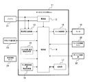
- FIG. 2 shows an outline of a functional configuration of the motor retractor ECU 11 (hereinafter abbreviated as “ECU 11” as appropriate).
- the ECU 11 includes a power supply unit 12, a power supply voltage monitoring unit 13, a control unit 14, an ECU internal / peripheral information acquisition unit 15, an ECU ambient temperature information acquisition unit 16, a recording unit 17, and a motor control unit 18, and a motor retractor. 3 performs drive control of the motor 19 included in the motor 3.
- the power supply unit 12 manages the electric power supplied from the battery 21 mounted on the vehicle for the internal power supply of the ECU 11.
- the voltage applied to the power supply unit 12 from the battery 21 is monitored by the power supply voltage monitoring unit 13, and information acquired by the power supply voltage monitoring unit 13 is provided to the control unit 14 as power supply voltage information.
- the control unit 14 includes a CPU, RAM, ROM, and the like (not shown), and executes a motor retractor control program stored in advance in the ROM while using a temporary storage function of the RAM. Thereby, the control unit 14 includes processes for overall control of various processes in the ECU 11 that are necessary for controlling the motor retractor 3, including a motor retractor control method shown in FIGS. 4 to 6 described later. And various devices mounted on the vehicle in relation to the electric seat belt device 1 are controlled through the device controller 22. The processing performed by the control unit 14 is recorded and stored by the recording unit 17 over time.
- control unit 14 corresponds to the calculation means described in the claims
- ECU 11 corresponds to the control device described in the claims.
- the various processes executed by the control unit 14 in accordance with the control of the motor retractor 3 mainly include various information acquisition processes.
- This information acquisition process includes an external information acquisition process and an internal information acquisition process, and the external information acquisition process includes a vehicle information acquisition process and a retractor information acquisition process.
- the control unit 14 acquires various types of information related to the vehicle outside the ECU 11 through the vehicle bus communication unit 23 and the vehicle information line 24.
- the retractor information acquisition process the control unit 14 transmits the information outside the ECU 11 through the retractor information line 25.
- Various information related to the motor retractor 3 (for example, information related to the rotation angle of the spool 3s in the motor retractor 3 and information related to the drawer lock of the webbing 2) is acquired.
- the internal information acquisition process mainly includes a power supply voltage information acquisition process, an ECU internal / peripheral information acquisition process, and an ECU ambient temperature information acquisition process.
- the control unit 14 acquires power supply voltage information through the power supply voltage monitoring unit 13 that monitors the applied voltage from the battery 21 as described above, and in the ECU internal / peripheral information acquisition process, Various information about the inside and the periphery of the ECU 11 is acquired through the peripheral information acquisition unit 15.
- information related to the ambient temperature around the ECU 11 is acquired as temperature information through the ECU atmosphere temperature information acquisition unit 16.
- the motor control unit 18 performs drive control on the motor 19 of the motor retractor 3 based on the control by the control unit 14.
- FIG. 3 shows an outline of the functional configuration of the control unit 14.
- the control unit 14 includes a voltage-related information acquisition unit 32, a drive current change determination unit 33, a target current value setting unit 34, a drive current selection unit 35, a threshold storage unit 36, a coefficient storage unit 37, and A target current value storage unit 38 is provided to selectively perform normal-time control (control in the normal-time control mode) and low-voltage control (control in the low-voltage control mode) when driving the webbing 2 during winding. .
- the control unit 14 supplies the motor 19 via the motor control unit 18 with a drive current based on the normal target current value 38d that is set in advance and stored in the target current value storage unit 38.
- the low voltage target current value 34d lower than the normal target current value 38d is set to the target current value setting unit based on the voltage related information 32d described later acquired by the voltage related information acquisition unit 32. 34, and the drive current based on the low voltage target current value 34 d is supplied to the motor 19 via the motor control unit 18.
- the selection between the normal time control and the low voltage control is performed according to the drive current change determination performed by the drive current change determination unit 33 based on the voltage-related information 32d. Specifically, low voltage control is performed on the condition that it is determined in the drive current change determination that the drive current of the motor 19 needs to be changed, and otherwise normal control is performed.
- the voltage-related information acquisition unit 32 acquires voltage-related information 32 d that is information about the voltage related to driving of the motor 19. The acquisition of the voltage related information 32d is always performed at regular time intervals. The voltage related information 32d acquired by the voltage related information acquisition unit 32 is provided to the drive current change determination unit 33 when necessary.
- As the voltage related information 32d there are power supply voltage information and voltage drop information, and when each of the power supply voltage information and the voltage drop information is independently voltage related information (first control mode and second control mode), There are cases where the power supply voltage information and the voltage drop information are both voltage-related information (third control mode).
- the control modes executed by the control unit 14 are summarized. As described above, there are a normal time control mode for normal time control and a low voltage time control mode for low voltage time control.
- the hour control mode includes the first to third control modes as described above.
- the power supply voltage information is acquired as information about the power supply that supplies the drive current to the motor 19, that is, the output voltage of the battery 21.
- the power supply voltage information is acquired by the power supply voltage monitoring unit 13 as a voltage applied to the power supply unit 12 from the battery 21 and provided to the voltage related information acquisition unit 32 of the control unit 14.
- the voltage drop information is acquired as information about the voltage drop in the drive current path that supplies the drive current to the motor 19.
- This voltage drop information may be either information when the drive current is supplied or not supplied, but is preferably acquired as information on the voltage drop in the drive current path when the drive current is supplied.
- the reason why the information about the voltage drop at the time of supplying the drive current is preferable is that the voltage drop has a high correlation with the current value flowing through the drive current path.
- the drive control of the motor 19 by the low voltage control as described later can be performed more effectively.
- the voltage drop has a high correlation with the temperature of the drive current path. This is because when the temperature rises, the resistance value of the drive current path increases and the voltage drop in the drive current path increases. Therefore, the voltage drop can be estimated with high accuracy based on the temperature of the drive current path. Therefore, in this embodiment, the voltage drop information is acquired as temperature information that is information about the ambient temperature of the drive current path.
- the control unit 14 acquires temperature information obtained by the ECU atmosphere temperature information acquisition process through the ECU atmosphere temperature information acquisition unit 16 described above. That is, information about the ambient temperature of the ECU 11 is used as temperature information of the drive current path.
- the ambient temperature of the ECU 11 is used as the temperature information of the drive current path.
- the drive current is supplied from the battery 21 to the motor 19 via the ECU 11 and the ECU 11 is generally mounted on the vehicle. This is because it can be said that there is no substantial difference between the ambient temperature of the ECU 11 and the ambient temperature of the drive current path of the motor 19. Therefore, if necessary, temperature information is acquired by vehicle information acquisition processing through the vehicle bus communication unit 23 and the vehicle information line 24 by the control unit 14 described above, and temperature information is obtained as an average value of the ambient temperature at a plurality of locations in the vehicle. May be obtained.
- temperature information is used as the voltage drop information.
- a voltage drop information by measuring the voltage drop in the drive current path to the motor 19 is also possible. In this case, it is preferable to actually measure the voltage drop when the drive current is supplied to the motor 19, that is, when the drive current is supplied when the motor 19 is driven.
- the voltage drop actual measurement value at the time of motor driving as the voltage drop information can be acquired at the current time point (time point at which drive control for the motor 19 is to be executed). Not exclusively. Therefore, as the voltage drop information based on the measured voltage drop at the time of driving the motor, the measured voltage drop at the time of driving the motor at the time closest to the current time may be used.
- the drive current is supplied to the motor 19 via the ECU 11.
- the ECU 11 is interposed in the drive current path of the motor 19, so that the influence of the voltage drop generated in the drive current path according to the current value of the drive current reaches the voltage of the internal power supply of the ECU 11.
- the drive current change determination unit 33 determines whether or not the motor drive current needs to be changed based on the voltage related information 32d provided from the voltage related information acquisition unit 32. Output to the target current value setting unit 34.
- the voltage related information 32d includes three types of power supply voltage information, temperature information (voltage drop information), power supply voltage information, and temperature information. There are three modes.
- the first determination mode is when the voltage-related information 32d is power supply voltage information, and the power supply voltage obtained from the power supply voltage information is compared with a voltage threshold taken out from the threshold storage unit 36, and the power supply voltage is lower than the voltage threshold. It is determined that the drive current needs to be changed.
- the second determination mode is a case where the voltage-related information 32d is temperature information, and compares the drive current path temperature (atmosphere temperature of the drive current path) obtained from the temperature information with a temperature threshold value taken out from the threshold value storage unit 36, When the drive current path temperature is higher than the temperature threshold, it is determined that the drive current needs to be changed.
- the third determination mode is a case where the voltage-related information 32d is the power supply voltage information and the temperature information, the drive current is changed when the power supply voltage is lower than the voltage threshold and the drive current path temperature is higher than the temperature threshold. It is determined that it is necessary.
- the target current value setting unit 34 receives the current change command 33d from the drive current change determination unit 33 and sets the target current value. Specifically, the low-voltage target current value 34d, which is a current value lower than the normal target current value 38d, is set based on the voltage-related information, and is output to the drive current selection unit 35.
- the target current value setting in the target current value setting unit 34 is performed according to which of the first to third determination modes the current change command 33d is described above. That is, in the case of using the first determination mode, the target current value setting unit 34 sets the low-voltage target current value as a current value corresponding to the power supply voltage obtained from the power supply voltage information, and the case of using the second determination mode. Sets the target current value at low voltage as a current value corresponding to the drive current path temperature obtained from the temperature information, and in the third determination mode, the current value according to both the power supply voltage and the drive current path temperature Set the target current value at low voltage.
- the drive current selection unit 35 selects the current value of the drive current supplied to the motor 19 and, as a result, selects either normal time control or low voltage control. Specifically, when the drive current change determination unit 33 determines that the drive current needs to be changed, that is, when the low-voltage target current value 34d is output from the target current value setting unit 34, the low voltage The drive current according to the hour target current value 34d is selected, and as a result, the low voltage control is selected. On the other hand, when the drive current change determination unit 33 determines that the drive current does not need to be changed, that is, when the target current value setting unit 34 does not output the low-voltage target current value 34d, the target current value is stored. The normal target current value 38d is extracted from the unit 38, the drive current based on the normal target current value 38d is selected, and as a result, the normal control is selected.
- the drive control performed by the ECU 11 with respect to the motor 19 includes the first to third control modes described above depending on what information is used as the voltage-related information 32d.
- FIG. 4 shows the control contents when drive control is performed in the first control mode. This flowchart is started by the control unit 14 when the control unit 14 outputs a winding command to the motor control unit 18.
- step S11 the control unit 14 first executes a voltage related information acquisition process.
- the voltage related information acquisition unit 32 of the control unit 14 acquires power supply voltage information as voltage related information.
- step S12 the control unit 14 performs a drive current change determination process for determining whether or not the drive current of the motor 19 needs to be changed based on the acquired power supply voltage information.
- the drive current change determination unit 33 that has acquired the power supply voltage information from the voltage related information acquisition unit 32 determines whether or not the power supply voltage obtained from the power supply voltage information is lower than the voltage threshold. When the power supply voltage is lower than the voltage threshold, it is determined that the drive current needs to be changed, and when the power supply voltage is equal to or higher than the voltage threshold, it is determined that the drive current need not be changed.
- step S15 the drive current selection unit 35 of the control unit 14 selects the drive current based on the normal target current value 38d and performs normal control, that is, normal target current. Control for driving the motor 19 with the drive current of the value 38d is executed, and the process is terminated. On the other hand, if the power supply voltage is lower than the voltage threshold, the process proceeds to step S13.
- step S13 the target current value setting unit 34 of the control unit 14 sets the low voltage target current value 34d.
- the low voltage target current value 34d in the first control mode is set as a current value lower than the normal target current value 38d based on the power supply voltage information as described above.
- the drive current selection unit 35 of the control unit 14 selects the drive current based on the low voltage target current value 34d, and controls the motor 19 with the low voltage control, that is, the drive current based on the low voltage target current value 34d. Is executed, and the process is terminated.
- step S11 corresponds to the voltage-related information acquisition procedure described in the claims
- step S12 corresponds to the determination procedure
- step S15 corresponds to the normal driving procedure
- steps S13 and S14 are the low voltage. This corresponds to the hour driving procedure.
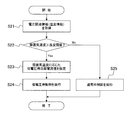
- FIG. 5 shows the control contents when drive control is performed in the second control mode. This flowchart is also started by the control unit 14 when the control unit 14 outputs a winding command to the motor control unit 18.
- step S21 the control unit 14 first executes a voltage related information acquisition process.
- the voltage related information acquisition unit 32 of the control unit 14 acquires temperature information as voltage related information.
- step S22 the control unit 14 performs a drive current change determination process for determining whether or not the drive current of the motor 19 needs to be changed based on the acquired temperature information.
- the drive current change determination unit 33 that has acquired the temperature information from the voltage related information acquisition unit 32 determines whether or not the ambient temperature obtained from the temperature information is higher than the temperature threshold. When the ambient temperature is higher than the temperature threshold, it is determined that the drive current needs to be changed. When the ambient temperature is equal to or lower than the temperature threshold, it is determined that the drive current does not need to be changed. When the ambient temperature is equal to or lower than the temperature threshold value, the process proceeds to step S25, the normal time control similar to step S15 described above is executed, and the process ends. On the other hand, if the ambient temperature is higher than the temperature threshold, the process proceeds to step S23.
- step S23 the target current value setting unit 34 of the control unit 14 sets the low voltage target current value 34d.
- the low voltage target current value 34d in the second control mode is set as a current value lower than the normal target current value 38d based on the temperature information as described above.
- step S24 the drive current selection unit 35 of the control unit 14 selects a drive current based on the low voltage target current value 34d, executes the low voltage control similar to step S14 described above, and ends the process. .
- Step S21 corresponds to the voltage-related information acquisition procedure described in the claims
- step S22 corresponds to the determination procedure
- step S25 corresponds to the normal driving procedure
- steps S23 and S24 are the low voltage. This corresponds to the hour driving procedure.
- FIG. 6 shows the contents of control when drive control is performed in the third control mode. This flowchart is also started by the control unit 14 when the control unit 14 outputs a winding command to the motor control unit 18.
- step S31 the control unit 14 first executes a voltage related information acquisition process.
- the voltage related information acquisition unit 32 of the control unit 14 acquires power supply voltage information and temperature information as voltage related information.
- step S32 and step S33 the control unit 14 determines whether or not the drive current of the motor 19 needs to be changed based on the acquired power supply voltage information and temperature information. Specifically, it is determined whether or not the motor drive current needs to be changed by a combination of the first drive current change determination process in step S32 and the second drive current change determination process in step S33.
- the drive current change determination unit 33 that has acquired the power supply voltage information from the voltage related information acquisition unit 32 determines whether the power supply voltage obtained from the power supply voltage information is lower than the voltage threshold. Determine. If the power supply voltage is equal to or higher than the voltage threshold, it is determined that there is no need to change the drive current, the process proceeds to step S36, the normal control similar to step S15 described above is executed, and the process ends.
- step S33 the drive current change determination process is performed.
- the drive current change determination unit 33 that has acquired the temperature information from the voltage related information acquisition unit 32 determines whether or not the ambient temperature obtained from the temperature information is higher than the temperature threshold. If the ambient temperature is equal to or lower than the temperature threshold, it is determined that there is no need to change the drive current, and the process proceeds to step S36. If the ambient temperature is higher than the temperature threshold, it is determined that the drive current needs to be changed, and the process proceeds to step S34.
- step S34 the target current value setting unit 34 of the control unit 14 sets the low voltage target current value 34d.
- the low voltage target current value 34d in the third control mode is set as a current value lower than the normal target current value 38d based on the power supply voltage information and the temperature information.
- the drive current selection unit 35 of the control unit 14 selects the drive current based on the low voltage target current value 34d, executes the low voltage control similar to the above-described step S14, and the like. Become.
- step S31 corresponds to the voltage-related information acquisition procedure described in the claims
- steps S32 and S33 correspond to the determination procedure
- step S36 corresponds to the normal driving procedure
- steps S34 and S35 Corresponds to a low voltage driving procedure.
- voltage-related information related to the drive voltage of the motor 19 can be acquired, and control according to the actual voltage state can be performed based on this voltage-related information.
- the battery 21 is weak and its output voltage becomes lower than a predetermined voltage threshold, and an insufficient voltage state is generated in the voltage of the power supply unit 12 of the ECU 11 and the applied voltage when the motor 19 is driven.
- control in which the low-voltage target current value 34d set according to the temperature condition is used in place of the normal target current value 38d. Also by this, the voltage of the power supply part 12 of ECU11 and the applied voltage at the time of the drive of the motor 19 can be ensured, and an insufficient voltage state can be avoided.
- the setting is made according to the battery voltage and the temperature condition.
- the functionality of the motor retractor 3 can be further improved. This will be described in detail.
- a target current value that enables stable operation of the motor retractor is set in advance on the assumption of a voltage drop in the assumed worst temperature environment, and the set target current Control using a fixed value is conceivable.
- the functionality of the motor retractor such as the operating speed of the motor retractor and the webbing take-up force (which is also the webbing occupant restraint force) and the operational stability of the motor retractor. Brought about.
- the operability of the motor retractor can be improved, while the voltage drop amount is increased and the operation stability of the motor retractor in a high temperature environment may be reduced. . Therefore, in the control using a fixed target current value, one of the functions of the motor retractor and the operational stability in a high temperature environment must be emphasized in relation to the voltage drop, and the other must be sacrificed. For example, if the target current value is given more importance on operating stability in the worst temperature environment where the voltage drop is large, the drive current value becomes lower than necessary under normal temperature environment, and the functionality of the motor retractor May be reduced.
- the trade-off relationship between the functionality of the motor retractor and the operational stability of the motor retractor in such control can be effectively eliminated by the control in the present embodiment. That is, in the motor drive control based on the target current value, the normal time control and the low voltage control can be selectively performed, and the target current value is set as the normal target current value and the low voltage target current value. Therefore, the normal target current value for normal control is not restricted by the worst temperature environment to be assumed. For this reason, the functionality of the motor retractor and the operational stability of the motor retractor can be made compatible, and therefore the trade-off relationship as described above can be effectively eliminated.
- the drive control function for selectively executing the normal time control and the low voltage control is provided to the control unit 14.
- a similar drive control function may be incorporated in the motor control unit 18.
- the drive current is supplied to the motor 19 via the ECU 11. Accordingly, the ECU 11 is interposed in the drive current path of the motor 19.
- the drive current path of the motor 19 is independent of the ECU 11. May be provided.
- the ambient temperature of the ECU 11 is acquired through the ECU ambient temperature information acquisition unit 16.
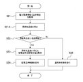
- the control unit 14 executes processing such as calorific value counter measurement for calculating the ECU calorific value when the motor is driven, for example, as shown in FIG.
- it may be determined in step S22 whether the ambient temperature is higher than a temperature threshold value.
- the step S21A corresponds to the temperature correction procedure described in the claims. Further, the temperature correction process may be applied to the flow shown in FIG. 6 to determine whether or not the drive current of the motor 19 needs to be changed based on the power supply voltage information and the corrected temperature information.
Landscapes
- Engineering & Computer Science (AREA)
- Mechanical Engineering (AREA)
- Automotive Seat Belt Assembly (AREA)
Abstract
【課題】制御装置の内部電源電圧やモータの駆動時印加電圧に電圧不足状態が発生するのを回避できるようにする。 【解決手段】モータ19の駆動電圧に関連する電圧関連情報として、ECU11の電源部12にバッテリ21から印加される電圧である電源電圧情報を取得し、この電源電圧情報に基づいて実際の電圧状況に応じた制御を行う。具体的には、バッテリ21が弱ってその出力電圧が所定の電圧閾値より低くなり、ECU11の電源部12の電圧やモータ19の駆動時印加電圧に電圧不足状態を発生させる可能性のある状況では、その低いバッテリ電圧に応じて設定する低電圧時目標電流値34dを通常時目標電流値38dに代えて用いる。
Description
本発明は、モータの駆動力によりウェビングの巻取りを行うモータリトラクタの制御方法及び制御プログラム、並びに、この制御方法を実行する制御装置を備えた電動式シートベルト装置に関する。
シートベルト装置は、車両に搭載され、車両の衝突事故時や急激な減速時に乗員を拘束する。そのためにシートベルト装置は、乗員拘束用のウェビング(シートベルト)、ウェビングを巻き取るシートベルトリトラクタ、及び乗員の拘束を可能とする状態にウェビングをセットするためのバックルなどで構成されている。
このようなシートベルト装置の一つとして、電動式のシートベルト装置がある。電動式シートベルト装置は、シートベルトリトラクタとしてモータリトラクタを備えている。モータリトラクタは、駆動用のモータを有し、ウェビングが巻回されたスプールをモータの駆動力で巻取り方向に回転させてウェビングの巻取りを行う。従来、制御装置を設け、ウェビングの巻取り動作などについてモータリトラクタの制御を行う電動式シートベルト装置が知られている(例えば、特許文献1及び特許文献2参照)。
電動式シートベルト装置におけるモータリトラクタの制御では、制御装置の作動電源やモータの駆動電源として車載のバッテリを用いている。制御装置やモータには、ワイヤハーネス等の電流路を通じてバッテリから電源が供給される。このようなモータリトラクタの制御にあっては、バッテリの出力電圧の低下や、雰囲気温度に応じた抵抗値の上昇に起因する電流路の電圧降下により、制御装置の内部電源の電圧やモータの駆動時印加電圧に電圧不足状態を招く可能性がある。ここで、電圧不足状態とは、制御装置の内部電源の電圧については、バッテリから電源が供給される内部電源の電圧が制御装置の安定的な作動に必要な電圧から不足する状態であり、駆動時印加電圧については、駆動時にモータに印加される電圧がモータの安定的な駆動に必要な電圧から不足している状態である。
そこで、電動式シートベルト装置の作動安定性をより高めて乗員の安全性を向上させるという観点から、電圧不足状態の発生を効果的に回避できるような制御が望まれるが、上記従来技術ではこのような制御は行われていなかった。
本発明の目的は、制御装置の内部電源電圧やモータの駆動時印加電圧に電圧不足状態が発生するのを回避できるモータリトラクタの制御方法及び制御プログラム、並びに、電動式シートベルト装置を提供することにある。
上記目的を達成するために、第1発明のモータリトラクタの制御方法は、モータの駆動力によりウェビングの巻取りを行うモータリトラクタの制御方法であって、前記モータの駆動電圧に関連する電圧関連情報を取得する電圧関連情報取得手順と、取得された前記電圧関連情報に基づき、前記モータの駆動電流を変更する必要があるか否かを判定する判定手順と、前記判定手順により前記モータの駆動電流を変更する必要がないと判定された場合に、予め設定された通常時目標電流値による駆動電流を供給して前記モータを駆動する通常時駆動手順と、前記判定手順により前記モータの駆動電流を変更する必要があると判定された場合に、前記電圧関連情報に基づいて前記通常時目標電流値より低い低電圧時目標電流値を設定し、この低電圧時目標電流値による駆動電流を供給して前記モータを駆動する低電圧時駆動手順と、を有することを特徴とする。
一般に電動式シートベルト装置におけるモータリトラクタの制御では、制御装置の作動電源やモータの駆動電源として車載のバッテリを用いている。したがって制御装置やモータには、ワイヤハーネス等の電流路を通じてバッテリから電源が供給されることになる。
このようなモータリトラクタの制御にあっては、制御装置の内部電源の電圧やモータの駆動時印加電圧に電圧不足状態を招く可能性がある。ここで、電圧不足状態とは、制御装置の内部電源の電圧については、バッテリから電源が供給される内部電源の電圧が制御装置の安定的な作動に必要な電圧から不足する状態であり、駆動時印加電圧については、駆動時にモータに印加される電圧がモータの安定的な駆動に必要な電圧から不足している状態である。なお、駆動時のモータへの電圧印加には、バッテリから電流路を通じて直接的にモータに印加される場合と、バッテリとモータの間に制御装置が介在する場合があり得る。
なお、このような電圧不足状態には、(1)バッテリの出力電圧で発生する場合、つまりバッテリの出力電圧が一定以下まで低下することで発生する場合、(2)電流路の電圧降下(これは電流路の抵抗値に影響する温度と相関し、また電流路に流れる電流値と相関する)で発生する場合、つまりバッテリから制御装置までの電流路、あるいはバッテリからモータまでの電流路の雰囲気温度が一定以上に高い状態にあることで、それら電流路における電圧降下が一定以上に大きくなって発生する場合、及び(3)バッテリの出力電圧と電流路の電圧降下が重なって発生する場合の3通りがあり得る。
ところで、電動式シートベルト装置の作動安定性をより高めて乗員の安全性を向上させるという観点からは、このような電圧不足状態の発生を効果的に回避できるような制御が望まれる。
そこで本願第1発明によれば、モータの駆動電圧に関連する電圧関連情報を取得し、この電圧関連情報に基づいて実際の電圧状況に応じた制御を行うことが可能となる。すなわち、上記(1)に記載のようにバッテリが弱ってその出力電圧が所定の電圧閾値より低くなり、制御装置の内部電源の電圧やモータの駆動時印加電圧に電圧不足状態を発生させる可能性のある状況では、その低いバッテリ電圧に応じて設定する低電圧時目標電流値を通常時目標電流値に代えて用いる制御を行うことが可能である。これにより、バッテリから制御装置までの電流路、あるいはバッテリからモータまでの電流路における電圧降下を減少させ、制御装置の内部電源の電圧やモータの駆動時印加電圧を確保し、電圧不足状態を回避することができる。
また上記(2)に記載のように、制御実行時の温度条件による電圧降下に起因して制御装置の内部電源の電圧やモータの駆動時印加電圧に電圧不足状態を発生させる可能性のある状況では、その温度条件に応じて設定する低電圧時目標電流値を通常時目標電流値に代えて用いる制御を行うことが可能となる。これによっても、バッテリから制御装置までの電流路、あるいはバッテリからモータまでの電流路における電圧降下を減少させ、制御装置の内部電源の電圧やモータの駆動時印加電圧を確保し、電圧不足状態を回避することができる。
さらに上記(3)に記載のように、バッテリの出力電圧と電流路の温度条件による電圧降下が重なって電圧不足状態を発生させる可能性のある状況では、それらのバッテリ電圧及び温度条件に応じて設定する低電圧時目標電流値を通常時目標電流値に代えて用いる制御を行うことにより、電圧不足状態を回避することができる。
以上のように、本願第1発明によれば、制御装置の内部電源電圧やモータの駆動時印加電圧に電圧不足状態が発生するのを効果的に回避し、制御装置の作動やモータの駆動に高い安定性を保つことができる。
第2発明のモータリトラクタの制御方法は、上記第1発明において、前記電圧関連情報取得手順は、前記電圧関連情報として、前記モータに駆動電流を供給する電源の電圧についての電源電圧情報を取得し、前記判定手順は、取得された前記電源電圧情報による前記電源の電圧が予め設定された電圧閾値より低い場合に、前記モータの駆動電流を変更する必要があると判定し、前記低電圧時駆動手順は、取得された前記電源電圧情報による前記電源の電圧に応じて前記低電圧時目標電流値を設定することを特徴とする。
本願第2発明においては、電圧関連情報として、モータに駆動電流を供給する電源の電圧についての電源電圧情報を取得し、電源の電圧が予め設定された電圧閾値より低い場合に、低電圧時目標電流値を通常時目標電流値に代えて用いる制御を行う。これにより、バッテリの出力電圧低下時でも、制御装置の内部電源の電圧やモータの駆動時印加電圧に電圧不足状態が発生するのを効果的に避けることができ、制御装置の作動やモータの駆動に高い安定性を保つことが可能となる。
第3発明のモータリトラクタの制御方法は、上記第1発明において、前記電圧関連情報取得手順は、前記電圧関連情報として、前記モータの駆動電流路の雰囲気温度についての温度情報を取得し、前記判定手順は、取得された前記温度情報による前記駆動電流路の雰囲気温度が予め設定された温度閾値より高い場合に、前記モータの駆動電流を変更する必要があると判定し、前記低電圧時駆動手順は、取得された前記温度情報による前記駆動電流路の雰囲気温度に応じて前記低電圧時目標電流値を設定することを特徴とする。
本願第3発明においては、電圧関連情報として、モータの駆動電流路の雰囲気温度についての温度情報を取得し、雰囲気温度が予め設定された温度閾値より高い場合に、低電圧時目標電流値を通常時目標電流値に代えて用いる制御を行う。これにより、モータの駆動電流路の雰囲気温度が上昇して電圧降下が大きくなる状況下でも、制御装置の内部電源の電圧やモータの駆動時印加電圧に電圧不足状態が発生するのを効果的に避けることができ、制御装置の作動やモータの駆動に高い安定性を保つことが可能となる。
第4発明のモータリトラクタの制御方法は、上記第1発明において、前記電圧関連情報取得手順は、前記電圧関連情報として、前記モータに駆動電流を供給する電源の電圧についての電源電圧情報、及び、前記モータの駆動電流路の雰囲気温度についての温度情報を取得し、前記判定手順は、取得された前記電源電圧情報による前記電源の電圧が予め設定された電圧閾値より低く、かつ、取得された前記温度情報による前記駆動電流路の雰囲気温度が予め設定された温度閾値より高い場合に、前記モータの駆動電流を変更する必要があると判定し、前記低電圧時駆動手順は、取得された前記電源電圧情報による前記電源の電圧、及び、取得された前記温度情報による前記駆動電流路の雰囲気温度に応じて前記低電圧時目標電流値を設定することを特徴とする。
本願第4発明においては、電圧関連情報として、モータに駆動電流を供給する電源の電圧についての電源電圧情報、及び、モータの駆動電流路の雰囲気温度についての温度情報を取得し、電源の電圧が予め設定された電圧閾値より低く、かつ、雰囲気温度が予め設定された温度閾値より高い場合に、低電圧時目標電流値を通常時目標電流値に代えて用いる制御を行う。これにより、バッテリの出力電圧が低下し、かつ、雰囲気温度の上昇により電圧降下が大きくなる状況下でも、制御装置の内部電源の電圧やモータの駆動時印加電圧に電圧不足状態が発生するのを効果的に避けることができ、制御装置の作動やモータの駆動に高い安定性を保つことが可能となる。
第5発明のモータリトラクタの制御方法は、上記第3発明において、前記電圧関連情報取得手順により取得された前記温度情報を、制御装置の発熱量に基づいて補正する温度補正手順を有し、前記判定手順は、補正された前記温度情報による前記駆動電流路の雰囲気温度が予め設定された温度閾値より高い場合に、前記モータの駆動電流を変更する必要があると判定することを特徴とする。
これにより、例えばモータ駆動後にモータ駆動回路の発熱により制御装置の雰囲気温度が上昇したとしても、当該発熱量に基づいて補正した温度を用いて、温度条件による電圧降下に起因して電圧不足状態が発生するか否かを正確に判定することができる。
上記目的を達成するために、第6発明のモータリトラクタの制御プログラムは、上記第1発明のモータリトラクタの制御方法を、前記モータリトラクタの制御装置に備えられた演算手段に実行させることを特徴とする。
当該制御プログラムを演算手段に実行させることにより、既存のモータリトラクタの制御装置を用いた場合でも、制御装置の内部電源電圧やモータの駆動時印加電圧に電圧不足状態が発生するのを効果的に回避することができる。
上記目的を達成するために、第7発明の電動式シートベルト装置は、乗員を拘束するウェビングと、前記ウェビングに摺動可能に取り付けられたタングと、前記タングが係合されるバックルと、前記ウェビングが通されるショルダアンカと、モータの駆動力により前記ウェビングの巻取りを行うモータリトラクタと、請求項1に記載の制御方法を実行することにより前記モータリトラクタを制御する制御装置と、を有することを特徴とする。
これにより、制御装置の内部電源電圧やモータの駆動時印加電圧に電圧不足状態が発生するのを効果的に回避できる電動式シートベルト装置を実現できる。
本発明によれば、制御装置の内部電源電圧やモータの駆動時印加電圧に電圧不足状態が発生するのを回避できる。
図1に、本発明の電動式シートベルト装置の一実施形態の全体構成を示す。図1に示す電動式シートベルト装置1は、ウェビング2、モータリトラクタ3、タング4、バックル5、ショルダアンカ6、及び止め具7を備え、車両の乗員Mを座席Sに拘束する。
ウェビング2は、一方側の端部が引き出し可能にモータリトラクタ3に巻き取られ、その途中がショルダアンカ6に通されつつ、他方側の端部が止め具7により車両の車体Bに回動可能に接続されている。乗員Mがウェビング2を装着する際には、ウェビング2に摺動可能に取り付けられているタング4でウェビング2をモータリトラクタ3から引き出し、タング4をバックル5に係合させる。これにより、ウェビング2が乗員Mを座席Sに拘束する状態となる。
モータリトラクタ3は、ウェビング2が巻回されたスプール3sを内蔵するとともに、後述するモータ19(図1では図示を省略、図2参照)をスプール3sの回転駆動用として備えている。このモータリトラクタ3は、スプール3sをモータ19の駆動力で巻取り方向に回転させてウェビング2の巻取りを行う。また電動式シートベルト装置1は、ウェビング2の巻取り動作などの制御のために、モータ19に接続されたモータリトラクタ用ECU(電子制御ユニット)11を有している。
図2に、モータリトラクタ用ECU11(以下では適宜「ECU11」と略記する)の機能構成の概要を示す。ECU11は、電源部12、電源電圧監視部13、制御部14、ECU内部・周辺情報取得部15、ECU雰囲気温度情報取得部16、記録部17、及びモータ制御部18を備えており、モータリトラクタ3が備えるモータ19の駆動制御を行う。
電源部12は、車両に搭載されたバッテリ21から供給される電力をECU11の内部電源用として管理する。この電源部12にバッテリ21から印加される電圧は、電源電圧監視部13により監視されており、電源電圧監視部13が取得する情報は、電源電圧情報として制御部14に提供される。
制御部14は、図示しないCPU、RAM、ROM等を有しており、RAMの一時記憶機能を利用しつつ、ROMに予め記憶されたモータリトラクタの制御プログラム等を実行する。これによって、制御部14は、後述の図4乃至図6に示すモータリトラクタの制御方法を含む、モータリトラクタ3の制御のために必要となるECU11での各種処理の全体的な制御のための処理を行うとともに、電動式シートベルト装置1に関連して車両に搭載されている各種デバイスの制御をデバイス制御部22を通じて行う。このような制御部14が行う処理は、記録部17により経時的に記録されて保存される。
なお、制御部14が特許請求の範囲に記載の演算手段に相当し、ECU11が特許請求の範囲に記載の制御装置に相当する。
モータリトラクタ3の制御に伴って制御部14が実行する各種処理には、主なものとして各種情報の取得処理が含まれる。この情報取得処理には、外部情報取得処理と内部情報取得処理が含まれており、さらに外部情報取得処理には、車両情報取得処理とリトラクタ情報取得処理が含まれている。制御部14は、車両情報取得処理では、車両バス通信部23や車両情報ライン24を通じてECU11の外部における車両に関する各種の情報を取得し、リトラクタ情報取得処理では、リトラクタ情報ライン25を通じてECU11の外部におけるモータリトラクタ3に関する各種情報(例えばモータリトラクタ3におけるスプール3sの回転角に関する情報、ウェビング2の引出しロックに関する情報など)を取得する。
一方、内部情報取得処理には、電源電圧情報取得処理、ECU内部・周辺情報取得処理、及びECU雰囲気温度情報取得処理が主なものとして含まれている。制御部14は、電源電圧情報取得処理では、上述のようにバッテリ21からの印加電圧を監視する電源電圧監視部13を通じて電源電圧情報を取得し、ECU内部・周辺情報取得処理では、ECU内部・周辺情報取得部15を通じてECU11の内部や周辺の各種情報を取得し、ECU雰囲気温度情報取得処理では、ECU雰囲気温度情報取得部16を通じてECU11の周囲の雰囲気温度に関する情報を温度情報として取得する。
モータ制御部18は、制御部14による制御に基づきモータリトラクタ3のモータ19に対する駆動制御を行う。
図3に、上記制御部14の機能構成の概要を示す。図3に示すように、制御部14は、電圧関連情報取得部32、駆動電流変更判定部33、目標電流値設定部34、駆動電流選択部35、閾値格納部36、係数格納部37、及び目標電流値格納部38を備え、ウェビング2の巻取り時の駆動制御に際し、通常時制御(通常時制御モードによる制御)と低電圧時制御(低電圧時制御モードによる制御)を選択的に行う。
制御部14は、通常時制御では、予め設定されて目標電流値格納部38に格納されている通常時目標電流値38dによる駆動電流をモータ制御部18を介してモータ19に供給する。一方、低電圧時制御では、電圧関連情報取得部32が取得する後述のような電圧関連情報32dに基づいて、通常時目標電流値38dより低い低電圧時目標電流値34dを目標電流値設定部34が設定し、その低電圧時目標電流値34dによる駆動電流をモータ制御部18を介してモータ19に供給する。通常時制御と低電圧時制御の選択は、電圧関連情報32dに基づいて駆動電流変更判定部33が行う駆動電流変更判定に応じて行われる。具体的には、駆動電流変更判定でモータ19の駆動電流を変更する必要があると判定されることを条件に低電圧時制御を行い、それ以外の場合は通常時制御を行う。
電圧関連情報取得部32は、モータ19の駆動に関係する電圧についての情報である電圧関連情報32dを取得する。電圧関連情報32dの取得は、一定時間間隔で常時行う。電圧関連情報取得部32が取得する電圧関連情報32dは、必要時に駆動電流変更判定部33に提供される。電圧関連情報32dとしては、電源電圧情報と電圧降下情報があり、電源電圧情報と電圧降下情報のそれぞれを単独に電圧関連情報とする場合(第1の制御モードと第2の制御モード)と、電源電圧情報と電圧降下情報をともに電圧関連情報とする場合(第3の制御モード)がある。ここで、制御部14で実行される制御のモードについて整理すると、上述のように通常時制御のための通常時制御モードと低電圧時制御のための低電圧時制御モードがあり、さらに低電圧時制御モードには、上記のような第1~第3の各制御モードがある。
電源電圧情報は、モータ19に駆動電流を供給する電源、つまりバッテリ21の出力電圧についての情報として取得される。本実施形態の場合、電源電圧情報は、電源部12にバッテリ21から印加される電圧として電源電圧監視部13により取得され、制御部14の電圧関連情報取得部32に提供される。
一方、電圧降下情報は、モータ19に駆動電流を供給する駆動電流路における電圧降下についての情報として取得される。この電圧降下情報は、駆動電流供給時及び非供給時のいずれの情報でもよいが、好ましくは駆動電流供給時の駆動電流路における電圧降下についての情報として取得される。駆動電流供給時の電圧降下についての情報を好ましいとするのは、電圧降下が駆動電流路に流れる電流値と高い相関性を有するからであり、駆動電流供給時の電圧降下を対象とすることにより、後述のような低電圧時制御によるモータ19の駆動制御をより効果的に行えるようになる。
電圧降下は、駆動電流路の温度とも高い相関性を有する。これは、温度が上昇すると駆動電流路の抵抗値が上昇し、駆動電流路における電圧降下が増大するためである。そのため駆動電流路の温度に基づいて電圧降下を高い精度で推定することができる。したがって本実施形態では、電圧降下情報は、駆動電流路の雰囲気温度についての情報である温度情報として取得される。具体的には、制御部14は、上述のECU雰囲気温度情報取得部16を通じて、ECU雰囲気温度情報取得処理で得られる温度情報を取得する。つまり駆動電流路の温度情報として、ECU11の雰囲気温度についての情報を用いている。
駆動電流路の温度情報としてECU11の雰囲気温度を用いるのは、本実施形態の場合、バッテリ21からECU11を介して駆動電流をモータ19に供給すること、それにECU11の車両への一般的な搭載場所などから考えて、ECU11の雰囲気温度とモータ19の駆動電流路の雰囲気温度に実質的な差異がないといえるからである。したがって必要に応じ、上述の制御部14による車両バス通信部23や車両情報ライン24を通じた車両情報取得処理で温度情報を取得したり、さらに車両中の複数箇所における雰囲気温度の平均値として温度情報を取得してもよい。
以上のように本実施例では電圧降下情報として温度情報を用いるが、モータ19への駆動電流路における電圧降下を実測して電圧降下情報とする形態も可能である。この場合、モータ19に駆動電流が供給されている状態、つまりモータ19が駆動している駆動電流供給時の電圧降下を実測するのが好ましい。但し、モータ19の駆動は不定期で行われることから、電圧降下情報としてのモータ駆動時の電圧降下実測値は、現在時点(モータ19に対する駆動制御を実行しようとする時点)について取得できるとは限らない。そこでモータ駆動時の電圧降下実測値による電圧降下情報には、現在時点に最も近い時点でのモータ駆動時の電圧降下実測値を用いればよい。
ここで、モータ19への駆動電流の供給は、ECU11を介して行われる。この場合、モータ19の駆動電流路にECU11が介在することになり、したがって駆動電流の電流値に応じて駆動電流路に生じる電圧降下の影響がECU11の内部電源の電圧に及ぶことになる。
駆動電流変更判定部33は、電圧関連情報取得部32から提供される電圧関連情報32dに基づいてモータ駆動電流の変更の要否を判定し、変更要と判定した場合には電流変更指令33dを目標電流値設定部34に出力する。上述のように電圧関連情報32dには、電源電圧情報、温度情報(電圧降下情報)、電源電圧情報及び温度情報の3種類があり、これに応じて駆動電流変更判定部33による判定には以下の3モードがある。
第1の判定モードは、電圧関連情報32dが電源電圧情報である場合で、電源電圧情報により得られる電源電圧を閾値格納部36から取り出す電圧閾値と比較し、その電源電圧が電圧閾値より低い場合に駆動電流変更の必要ありと判定する。また第2の判定モードは、電圧関連情報32dが温度情報である場合で、温度情報により得られる駆動電流路温度(駆動電流路の雰囲気温度)を閾値格納部36から取り出す温度閾値と比較し、その駆動電流路温度が温度閾値より高い場合に駆動電流変更の必要ありと判定する。さらに第3の判定モードは、電圧関連情報32dが電源電圧情報及び温度情報である場合で、電源電圧が電圧閾値より低い場合で、かつ、駆動電流路温度が温度閾値より高い場合に駆動電流変更の必要ありと判定する。
目標電流値設定部34は、駆動電流変更判定部33からの電流変更指令33dを受けて目標電流値の設定を行う。具体的には、通常時目標電流値38dより低い電流値である低電圧時目標電流値34dを電圧関連情報に基づいて設定し、それを駆動電流選択部35に出力する。目標電流値設定部34における目標電流値設定は、電流変更指令33dが上述の第1~第3の各判定モードのいずれによるかに応じて行われる。すなわち、目標電流値設定部34は、第1の判定モードによる場合は、電源電圧情報により得られる電源電圧に応じた電流値として低電圧時目標電流値を設定し、第2の判定モードによる場合は、温度情報により得られる駆動電流路温度に応じた電流値として低電圧時目標電流値を設定し、第3の判定モードによる場合は、電源電圧と駆動電流路温度の両者に応じた電流値として低電圧時目標電流値を設定する。
ここで、電源電圧に応じた低電圧時目標電流値の設定は、例えば、係数格納部37に格納してある電圧用係数Keを用い、低電圧時目標電流値=通常時目標電流値-電源電圧×Keといった導出式で行われる。また、駆動電流路温度に応じた低電圧時目標電流値の設定は、係数格納部37に格納してある温度用係数Ktを用い、低電圧時目標電流値=通常時目標電流値-駆動電流路温度×Ktといった導出式で行われる。また、電源電圧と駆動電流路温度の両者に応じた低電圧時目標電流値の設定は、電圧用係数Keと温度用係数Ktを用い、低電圧時目標電流値=通常時目標電流値-(電圧×Ke+駆動電流路温度×Kt)といった導出式で行われる。なお、これらは低電圧時目標電流値の設定方法の一例であり、他の設定方法を用いてもよい。
駆動電流選択部35は、モータ19に供給する駆動電流の電流値を選択し、その結果として通常時制御と低電圧時制御のいずれかを選択する。具体的には、駆動電流変更判定部33が駆動電流を変更する必要があると判定した場合、つまり目標電流値設定部34から低電圧時目標電流値34dが出力された場合には、低電圧時目標電流値34dによる駆動電流を選択し、その結果として低電圧時制御が選択される。一方、駆動電流変更判定部33が駆動電流を変更する必要がないと判定した場合、つまり目標電流値設定部34から低電圧時目標電流値34dが出力されなかった場合には、目標電流値格納部38から通常時目標電流値38dを取り出し、その通常時目標電流値38dによる駆動電流を選択し、その結果として通常時制御が選択される。
以下では、上述のようなECU11が実行するモータリトラクタ3のモータ19に対する駆動制御の内容について説明する。上述したように、ECU11がモータ19に対して行う駆動制御には、電圧関連情報32dとしてどのような情報を用いるかに応じて、上述の第1~第3の各制御モードがある。
図4に、第1の制御モードでの駆動制御を行う場合の制御内容を示す。このフローチャートは、制御部14がモータ制御部18に巻取り指令を出力した際に制御部14によって開始される。
ステップS11では、制御部14は、まず電圧関連情報取得処理を実行する。この処理では、制御部14の電圧関連情報取得部32が電圧関連情報として電源電圧情報を取得する。
次にステップS12では、制御部14は、取得した電源電圧情報に基づいてモータ19の駆動電流を変更する必要があるか否かを判定する駆動電流変更判定処理を行う。この駆動電流変更判定処理では、電圧関連情報取得部32より電源電圧情報を取得した駆動電流変更判定部33が、電源電圧情報により得られる電源電圧が電圧閾値より低いか否かを判定する。電源電圧が電圧閾値より低い場合には、駆動電流を変更する必要があると判定し、電源電圧が電圧閾値以上である場合には、駆動電流を変更する必要はないと判定する。電源電圧が電圧閾値以上である場合には、ステップS15に進み、制御部14の駆動電流選択部35は、通常時目標電流値38dによる駆動電流を選択し、通常時制御、つまり通常時目標電流値38dによる駆動電流でモータ19を駆動する制御を実行し、処理を終了する。一方、電源電圧が電圧閾値より低い場合には、ステップS13に進む。
ステップS13では、制御部14の目標電流値設定部34が低電圧時目標電流値34dの設定を行う。第1の制御モードでの低電圧時目標電流値34dは、上述のように、電源電圧情報に基づいて通常時目標電流値38dより低い電流値として設定される。
次のステップS14では、制御部14の駆動電流選択部35は、低電圧時目標電流値34dによる駆動電流を選択し、低電圧時制御、つまり低電圧時目標電流値34dによる駆動電流でモータ19を駆動する制御を実行し、処理を終了する。
なお、上記ステップS11が特許請求の範囲に記載の電圧関連情報取得手順に相当し、ステップS12が判定手順に相当し、ステップS15が通常時駆動手順に相当し、ステップS13及びステップS14が低電圧時駆動手順に相当する。
図5に、第2の制御モードでの駆動制御を行う場合の制御内容を示す。本フローチャートも、制御部14がモータ制御部18に巻取り指令を出力した際に制御部14によって開始される。
ステップS21では、制御部14は、まず電圧関連情報取得処理を実行する。この処理では、制御部14の電圧関連情報取得部32が電圧関連情報として温度情報を取得する。
次にステップS22では、制御部14は、取得した温度情報に基づいてモータ19の駆動電流を変更する必要があるか否かを判定する駆動電流変更判定処理を行う。この駆動電流変更判定処理では、電圧関連情報取得部32より温度情報を取得した駆動電流変更判定部33が、温度情報により得られる雰囲気温度が温度閾値より高いか否かを判定する。雰囲気温度が温度閾値より高い場合には、駆動電流を変更する必要があると判定し、雰囲気温度が温度閾値以下である場合には、駆動電流を変更する必要はないと判定する。雰囲気温度が温度閾値以下である場合には、ステップS25に進み、上述のステップS15と同様の通常時制御を実行し、処理を終了する。一方、雰囲気温度が温度閾値より高い場合には、ステップS23に進む。
ステップS23では、制御部14の目標電流値設定部34が低電圧時目標電流値34dの設定を行う。第2の制御モードでの低電圧時目標電流値34dは、上述のように、温度情報に基づいて通常時目標電流値38dより低い電流値として設定される。
次のステップS24では、制御部14の駆動電流選択部35は、低電圧時目標電流値34dによる駆動電流を選択し、上述のステップS14と同様の低電圧時制御を実行し、処理を終了する。
なお、上記ステップS21が特許請求の範囲に記載の電圧関連情報取得手順に相当し、ステップS22が判定手順に相当し、ステップS25が通常時駆動手順に相当し、ステップS23及びステップS24が低電圧時駆動手順に相当する。
図6に、第3の制御モードでの駆動制御を行う場合の制御内容を示す。本フローチャートも、制御部14がモータ制御部18に巻取り指令を出力した際に制御部14によって開始される。
ステップS31では、制御部14は、まず電圧関連情報取得処理を実行する。この処理では、制御部14の電圧関連情報取得部32が電圧関連情報として電源電圧情報と温度情報を取得する。
次にステップS32及びステップS33では、制御部14は、取得した電源電圧情報と温度情報に基づいてモータ19の駆動電流を変更する必要があるか否かを判定する。具体的には、ステップS32における第1の駆動電流変更判定処理とステップS33における第2の駆動電流変更判定処理の組み合わせでモータ駆動電流の変更の要否を判定する。ステップS32における第1の駆動電流変更判定処理では、電圧関連情報取得部32より電源電圧情報を取得した駆動電流変更判定部33が、電源電圧情報により得られる電源電圧が電圧閾値より低いか否かを判定する。電源電圧が電圧閾値以上である場合には、駆動電流を変更する必要はないと判定し、ステップS36に進み、上述のステップS15等と同様の通常時制御を実行し、処理を終了する。
一方、電源電圧が電圧閾値より低い場合には、ステップS33に進み、第2の駆動電流変更判定処理を行う。この第2の駆動電流変更判定処理では、電圧関連情報取得部32より温度情報を取得した駆動電流変更判定部33が、温度情報により得られる雰囲気温度が温度閾値より高いか否かを判定する。雰囲気温度が温度閾値以下である場合には、駆動電流を変更する必要はないと判定し、ステップS36に進む。雰囲気温度が温度閾値より高い場合には、駆動電流を変更する必要があると判定し、ステップS34に進む。
ステップS34では、制御部14の目標電流値設定部34が低電圧時目標電流値34dの設定を行う。第3の制御モードでの低電圧時目標電流値34dは、上述のように、電源電圧情報と温度情報に基づいて通常時目標電流値38dより低い電流値として設定される。
次のステップS35では、制御部14の駆動電流選択部35は、低電圧時目標電流値34dによる駆動電流を選択し、上述のステップS14等と同様の低電圧時制御を実行し、処理終了となる。
なお、上記ステップS31が特許請求の範囲に記載の電圧関連情報取得手順に相当し、ステップS32及びステップS33が判定手順に相当し、ステップS36が通常時駆動手順に相当し、ステップS34及びステップS35が低電圧時駆動手順に相当する。
以上説明した実施形態によれば、モータ19の駆動電圧に関連する電圧関連情報を取得し、この電圧関連情報に基づいて実際の電圧状況に応じた制御を行うことができる。具体的には、第1の制御モードでは、バッテリ21が弱ってその出力電圧が所定の電圧閾値より低くなり、ECU11の電源部12の電圧やモータ19の駆動時印加電圧に電圧不足状態を発生させる可能性のある状況において、その低いバッテリ電圧に応じて設定する低電圧時目標電流値34dを通常時目標電流値38dに代えて用いる制御を行う。これにより、バッテリ21からECU11までの電流路、あるいはバッテリ21からモータ19までの電流路における電圧降下を減少させ、ECU11の電源部12の電圧やモータ19の駆動時印加電圧を確保し、電圧不足状態を回避することができる。
また第2の制御モードでは、制御実行時の温度条件による電圧降下に起因してECU11の電源部12の電圧やモータ19の駆動時印加電圧に電圧不足状態を発生させる可能性のある状況において、その温度条件に応じて設定する低電圧時目標電流値34dを通常時目標電流値38dに代えて用いる制御を行う。これによっても、ECU11の電源部12の電圧やモータ19の駆動時印加電圧を確保し、電圧不足状態を回避することができる。
さらに第3の制御モードでは、バッテリ21の出力電圧と電流路の温度条件による電圧降下が重なって電圧不足状態を発生させる可能性のある状況において、それらのバッテリ電圧及び温度条件に応じて設定する低電圧時目標電流値34dを通常時目標電流値38dに代えて用いる制御を行うことにより、電圧不足状態を回避することができる。
以上のように、本実施形態によれば、ECU11の電源部12の電圧やモータ19の駆動時印加電圧に電圧不足状態が発生するのを効果的に回避し、ECU11の作動やモータ19の駆動に高い安定性を保つことができる。
さらに本実施形態によれば、モータリトラクタ3の機能性をより向上させることも可能となる。この詳細について説明する。例えば、電圧不足状態の回避のために、想定される最悪な温度環境での電圧降下を前提にしてモータリトラクタの安定的な作動を可能とする目標電流値を予め設定し、その設定した目標電流値を固定的に用いる制御が考えられる。このような制御では、モータリトラクタにおける動作速度やウェビング巻取り力(これはウェビングの乗員拘束力でもある)といったモータリトラクタの機能性とモータリトラクタの作動安定性の間に、トレードオフ的な関係がもたらされる。すなわち、固定の目標電流値を大きくするほど、モータリトラクタの作動性を高めることができる一方で、電圧降下量が大きくなって高温環境下でのモータリトラクタの作動安定性を低下させる可能性がある。したがって、固定の目標電流値を用いる制御では、電圧降下との関係でモータリトラクタの機能性と高温環境下での作動安定性のいずれか一方を重視し、他方を犠牲にせざるを得ないことになり、例えば電圧降下量が大きくなる最悪な温度環境下での作動安定性をより重視した目標電流値にした場合、通常の温度環境下では必要以上に低い駆動電流値となり、モータリトラクタの機能性を低下させるおそれがある。
このような制御におけるモータリトラクタの機能性とモータリトラクタの作動安定性の間のトレードオフ的な関係は、本実施形態における制御によれば、効果的に解消することができる。すなわち、目標電流値に基づくモータ駆動制御にあって、通常時制御と低電圧時制御を選択的に行えるようにし、目標電流値を通常時目標電流値と低電圧時目標電流値として、状況に応じて使い分けることができるので、想定すべき最悪な温度環境によって通常時制御用の通常時目標電流値が縛られることがない。このため、モータリトラクタの機能性とモータリトラクタの作動安定性を両立させることが可能となり、したがって上記のようなトレードオフ的な関係を効果的に解消することができる。
以上、本発明を実施するための形態について説明したが、これは代表的な例に過ぎず、本発明はその趣旨を逸脱することのない範囲で様々な形態で実施することができる。例えば、上記形態では、通常時制御と低電圧時制御を選択的に実行する駆動制御機能を制御部14にもたせるようにしたが、同様の駆動制御機能をモータ制御部18に組み込む形態としてもよい。また上記形態は、ECU11を介してモータ19に駆動電流を供給する場合であり、したがってモータ19の駆動電流路にECU11が介在する場合であったが、ECU11とは独立にモータ19の駆動電流路を設ける形態であってもよい。
また、上記実施形態においては、ECU11の雰囲気温度をECU雰囲気温度情報取得部16を通じて取得しているが、モータ駆動後などは図示しないモータ駆動回路の発熱により雰囲気温度が上昇することが考えられる。したがって、制御部14が、モータ駆動時のECU発熱量を計算する発熱量カウンタ計測等の処理を実行する場合には、例えば図7に示すように、ステップS21Aにおいて発熱カウンタの計測値に基づき温度補正を行った上で、ステップS22において雰囲気温度が温度閾値より高いか否かを判定するようにしてもよい。これにより、上記モータ駆動回路の発熱等が生じている場合でも、温度条件による電圧降下に起因して電圧不足状態が発生するか否かを正確に判定することができる。なお、上記ステップS21Aが特許請求の範囲に記載の温度補正手順に相当する。また、当該温度補正処理を図6に示すフローに適用し、電源電圧情報と補正した温度情報とに基づいてモータ19の駆動電流を変更する必要があるか否かを判定してもよい。
1 電動式シートベルト装置
2 ウェビング
3 モータリトラクタ
11 モータリトラクタ用ECU(制御装置)
14 制御部(演算手段)
19 モータ
32d 電圧関連情報
34d 低電圧時目標電流値
38d 通常時目標電流値
2 ウェビング
3 モータリトラクタ
11 モータリトラクタ用ECU(制御装置)
14 制御部(演算手段)
19 モータ
32d 電圧関連情報
34d 低電圧時目標電流値
38d 通常時目標電流値
Claims (7)
- モータ(19)の駆動力によりウェビング(2)の巻取りを行うモータリトラクタの制御方法であって、
前記モータ(19)の駆動電圧に関連する電圧関連情報を取得する電圧関連情報取得手順(S1;S21;S31)と、
取得された前記電圧関連情報に基づき、前記モータ(19)の駆動電流を変更する必要があるか否かを判定する判定手順(S12;S22;S32,S33)と、
前記判定手順により前記モータ(19)の駆動電流を変更する必要がないと判定された場合に、予め設定された通常時目標電流値による駆動電流を供給して前記モータ(19)を駆動する通常時駆動手順(S15;S25;S36)と、
前記判定手順により前記モータ(19)の駆動電流を変更する必要があると判定された場合に、前記電圧関連情報に基づいて前記通常時目標電流値より低い低電圧時目標電流値を設定し、この低電圧時目標電流値による駆動電流を供給して前記モータ(19)を駆動する低電圧時駆動手順(S13,S14;S23,S24;S34,S35)と、
を有することを特徴とするモータリトラクタの制御方法。 - 請求項1記載のモータリトラクタの制御方法において、
前記電圧関連情報取得手順(S1)は、
前記電圧関連情報として、前記モータ(19)に駆動電流を供給する電源の電圧についての電源電圧情報を取得し、
前記判定手順(S12)は、
取得された前記電源電圧情報による前記電源の電圧が予め設定された電圧閾値より低い場合に、前記モータ(19)の駆動電流を変更する必要があると判定し、
前記低電圧時駆動手順(S13,S14)は、
取得された前記電源電圧情報による前記電源の電圧に応じて前記低電圧時目標電流値を設定する
ことを特徴とするモータリトラクタの制御方法。 - 請求項1記載のモータリトラクタの制御方法において、
前記電圧関連情報取得手順(S21)は、
前記電圧関連情報として、前記モータ(19)の駆動電流路の雰囲気温度についての温度情報を取得し、
前記判定手順(S22)は、
取得された前記温度情報による前記駆動電流路の雰囲気温度が予め設定された温度閾値より高い場合に、前記モータ(19)の駆動電流を変更する必要があると判定し、
前記低電圧時駆動手順(S23,S24)は、
取得された前記温度情報による前記駆動電流路の雰囲気温度に応じて前記低電圧時目標電流値を設定する
ことを特徴とするモータリトラクタの制御方法。 - 請求項1記載のモータリトラクタの制御方法において、
前記電圧関連情報取得手順(S31)は、
前記電圧関連情報として、前記モータ(19)に駆動電流を供給する電源の電圧についての電源電圧情報、及び、前記モータ(19)の駆動電流路の雰囲気温度についての温度情報を取得し、
前記判定手順(S32,S33)は、
取得された前記電源電圧情報による前記電源の電圧が予め設定された電圧閾値より低く、かつ、取得された前記温度情報による前記駆動電流路の雰囲気温度が予め設定された温度閾値より高い場合に、前記モータ(19)の駆動電流を変更する必要があると判定し、
前記低電圧時駆動手順(S34,S35)は、
取得された前記電源電圧情報による前記電源の電圧、及び、取得された前記温度情報による前記駆動電流路の雰囲気温度に応じて前記低電圧時目標電流値を設定する
ことを特徴とするモータリトラクタの制御方法。 - 請求項3に記載のモータリトラクタの制御方法において、
前記電圧関連情報取得手順により取得された前記温度情報を、制御装置の発熱量に基づいて補正する温度補正手順(S21A)を有し、
前記判定手順(S22)は、
補正された前記温度情報による前記駆動電流路の雰囲気温度が予め設定された温度閾値より高い場合に、前記モータ(19)の駆動電流を変更する必要があると判定する
ことを特徴とするモータリトラクタの制御方法。 - 請求項1に記載のモータリトラクタの制御方法を、
前記モータリトラクタの制御装置(11)に備えられた演算手段(14)に実行させるための、モータリトラクタの制御プログラム。 - 乗員(M)を拘束するウェビング(2)と、
前記ウェビング(2)に摺動可能に取り付けられたタング(4)と、
前記タング(4)が係合されるバックル(5)と、
前記ウェビング(2)が通されるショルダアンカ(6)と、
モータ(19)の駆動力により前記ウェビング(2)の巻取りを行うモータリトラクタ(3)と、
請求項1に記載の制御方法を実行することにより前記モータリトラクタ(3)を制御する制御装置(11)と、
を有することを特徴とする電動式シートベルト装置(1)。
Applications Claiming Priority (2)
| Application Number | Priority Date | Filing Date | Title |
|---|---|---|---|
| JP2010211253A JP5557284B2 (ja) | 2010-09-21 | 2010-09-21 | モータリトラクタの制御方法、制御プログラム、電動式シートベルト装置 |
| JP2010-211253 | 2010-09-21 |
Publications (1)
| Publication Number | Publication Date |
|---|---|
| WO2012039191A1 true WO2012039191A1 (ja) | 2012-03-29 |
Family
ID=45873686
Family Applications (1)
| Application Number | Title | Priority Date | Filing Date |
|---|---|---|---|
| PCT/JP2011/066827 Ceased WO2012039191A1 (ja) | 2010-09-21 | 2011-07-25 | モータリトラクタの制御方法、制御プログラム、電動式シートベルト装置 |
Country Status (2)
| Country | Link |
|---|---|
| JP (1) | JP5557284B2 (ja) |
| WO (1) | WO2012039191A1 (ja) |
Families Citing this family (1)
| Publication number | Priority date | Publication date | Assignee | Title |
|---|---|---|---|---|
| KR102029793B1 (ko) * | 2013-05-09 | 2019-10-08 | 현대모비스 주식회사 | 차량의 시트벨트 리트랙터의 모터 제어방법 |
Citations (1)
| Publication number | Priority date | Publication date | Assignee | Title |
|---|---|---|---|---|
| JP2008143275A (ja) * | 2006-12-07 | 2008-06-26 | Takata Corp | シートベルト巻き取り制御装置、シートベルト巻き取り装置、シートベルト巻き取り制御方法、及びプログラム |
-
2010
- 2010-09-21 JP JP2010211253A patent/JP5557284B2/ja not_active Expired - Fee Related
-
2011
- 2011-07-25 WO PCT/JP2011/066827 patent/WO2012039191A1/ja not_active Ceased
Patent Citations (1)
| Publication number | Priority date | Publication date | Assignee | Title |
|---|---|---|---|---|
| JP2008143275A (ja) * | 2006-12-07 | 2008-06-26 | Takata Corp | シートベルト巻き取り制御装置、シートベルト巻き取り装置、シートベルト巻き取り制御方法、及びプログラム |
Also Published As
| Publication number | Publication date |
|---|---|
| JP2012066636A (ja) | 2012-04-05 |
| JP5557284B2 (ja) | 2014-07-23 |
Similar Documents
| Publication | Publication Date | Title |
|---|---|---|
| JP4934400B2 (ja) | 車両のシートベルト装置 | |
| JP4183728B2 (ja) | シートベルトリトラクタの電気モータに供給される電流の制御 | |
| US9000771B2 (en) | Automotive battery circuit fault detection | |
| JP4889579B2 (ja) | 車両のシートベルト装置 | |
| JP4573225B2 (ja) | シートベルトの巻き取り方法 | |
| JP2008099525A (ja) | 発電制御装置 | |
| JP5557284B2 (ja) | モータリトラクタの制御方法、制御プログラム、電動式シートベルト装置 | |
| EP2543560B1 (en) | Seat belt control device, seat belt retractor, seat belt device, seat belt control method, and program | |
| US9139160B2 (en) | Active seat belt apparatus and method | |
| JP5765138B2 (ja) | 拘束装置 | |
| JP3695622B2 (ja) | 車両用乗員拘束保護装置 | |
| US8783725B2 (en) | Restraint device | |
| WO2008069067A1 (ja) | シートベルト巻き取り制御装置、シートベルト巻き取り装置、シートベルト装置、シートベルト巻き取り制御方法、及びプログラム | |
| CN106464179A (zh) | 用于控制安全带卷收器的卷收电机的电机转速的方法 | |
| JP4567573B2 (ja) | シートベルト装置 | |
| KR20150011090A (ko) | 능동형 시트벨트 장치 | |
| KR102217808B1 (ko) | 정전용량을 이용한 구동모터의 진단장치 및 그 방법 | |
| JP2008030668A (ja) | 車両のシートベルト装置 | |
| JP2009040303A (ja) | ウエビング巻取装置 | |
| JP2008024207A (ja) | シートベルト装置 | |
| JP6277481B2 (ja) | シートベルト装置 | |
| KR102029793B1 (ko) | 차량의 시트벨트 리트랙터의 모터 제어방법 | |
| JP5640068B2 (ja) | シートベルト装置 | |
| JP6087059B2 (ja) | シートベルトの制御装置 | |
| JP5013169B2 (ja) | 車両のシートベルト制御装置 |
Legal Events
| Date | Code | Title | Description |
|---|---|---|---|
| 121 | Ep: the epo has been informed by wipo that ep was designated in this application |
Ref document number: 11826637 Country of ref document: EP Kind code of ref document: A1 |
|
| NENP | Non-entry into the national phase |
Ref country code: DE |
|
| 122 | Ep: pct application non-entry in european phase |
Ref document number: 11826637 Country of ref document: EP Kind code of ref document: A1 |