WO2012039043A1 - ステレオ画像生成装置、ステレオ画像生成方法及びステレオ画像生成用コンピュータプログラム - Google Patents
ステレオ画像生成装置、ステレオ画像生成方法及びステレオ画像生成用コンピュータプログラム Download PDFInfo
- Publication number
- WO2012039043A1 WO2012039043A1 PCT/JP2010/066450 JP2010066450W WO2012039043A1 WO 2012039043 A1 WO2012039043 A1 WO 2012039043A1 JP 2010066450 W JP2010066450 W JP 2010066450W WO 2012039043 A1 WO2012039043 A1 WO 2012039043A1
- Authority
- WO
- WIPO (PCT)
- Prior art keywords
- image
- point
- coefficient
- movement component
- rotational movement
- Prior art date
Links
Images


Classifications
-
- H—ELECTRICITY
- H04—ELECTRIC COMMUNICATION TECHNIQUE
- H04N—PICTORIAL COMMUNICATION, e.g. TELEVISION
- H04N13/00—Stereoscopic video systems; Multi-view video systems; Details thereof
- H04N13/20—Image signal generators
- H04N13/204—Image signal generators using stereoscopic image cameras
- H04N13/207—Image signal generators using stereoscopic image cameras using a single 2D image sensor
- H04N13/211—Image signal generators using stereoscopic image cameras using a single 2D image sensor using temporal multiplexing
-
- G—PHYSICS
- G06—COMPUTING; CALCULATING OR COUNTING
- G06T—IMAGE DATA PROCESSING OR GENERATION, IN GENERAL
- G06T7/00—Image analysis
- G06T7/80—Analysis of captured images to determine intrinsic or extrinsic camera parameters, i.e. camera calibration
- G06T7/85—Stereo camera calibration
-
- H—ELECTRICITY
- H04—ELECTRIC COMMUNICATION TECHNIQUE
- H04N—PICTORIAL COMMUNICATION, e.g. TELEVISION
- H04N13/00—Stereoscopic video systems; Multi-view video systems; Details thereof
- H04N13/20—Image signal generators
- H04N13/204—Image signal generators using stereoscopic image cameras
- H04N13/239—Image signal generators using stereoscopic image cameras using two 2D image sensors having a relative position equal to or related to the interocular distance
-
- H—ELECTRICITY
- H04—ELECTRIC COMMUNICATION TECHNIQUE
- H04N—PICTORIAL COMMUNICATION, e.g. TELEVISION
- H04N13/00—Stereoscopic video systems; Multi-view video systems; Details thereof
- H04N13/20—Image signal generators
- H04N13/204—Image signal generators using stereoscopic image cameras
- H04N13/246—Calibration of cameras
Definitions
- the present invention relates to, for example, a stereo image generation apparatus, a stereo image generation method, and a computer program for stereo image generation that generate a stereo image based on two images obtained by photographing the same object from different directions.
- a first image is created by photographing a target object at a first point using one camera, and then the camera is moved to a second point.
- a second image is created by photographing the target object.
- the first image and the second image are created by photographing the target object with two cameras arranged at the first point and the second point.
- the first image and the second image are a set of stereo images.
- the images projected on the two images are It is preferable that the image is taken under the same conditions as the conditions under which an observer generally sees an object. Since the left and right eyes of a human are aligned in the horizontal direction, it is preferable that the first point and the second point are also aligned horizontally. In addition, since the lines of sight of the left and right eyes are substantially parallel, the optical axis of the camera at the first point and the optical axis of the camera at the second point are preferably parallel to each other.
- the photographer In order to accurately arrange the cameras in this way at the first point and the second point, the photographer must perform a strict alignment adjustment. Therefore, the position and orientation of the camera at the first point and the second point are measured, and the arrangement of the camera is adjusted according to the measurement result.
- strict alignment adjustment for example, an operator performs surveying using a measuring instrument for surveying, or performs various manual operations for adjusting the position of the camera according to the result. become. Therefore, enormous costs and work time are required to create a stereo image. Therefore, in practice, it is often difficult to perform such exact alignment adjustment.
- the camera height at the first point is different from the camera height at the second point, or the camera optical axis direction at the first point is different from the camera optical axis direction at the second point.
- one image rotates around the optical axis with respect to the other image.
- Patent Document 1 a technique for creating an image suitable for a stereo image by converting the position of the image on the image has been proposed (see, for example, Patent Document 1 and Non-Patent Document 1).
- the camera characteristics such as camera focal length and distortion aberration are corrected so as to correct the camera height at two points at the time of shooting, the difference in the optical axis direction, and the deviation of rotation around the optical axis.
- the position of the image on the image is converted in consideration.
- An image processing apparatus determines a rotation method or a rotation translation method of planar projection conversion so that corresponding feature points extracted from two images match each other. Then, the image processing apparatus generates a stereo image by converting the position of each point on the image using a rotation type or a rotation translation type.
- another known image processing apparatus generates a stereo image by converting an image in consideration of epipolar geometry.
- the epipolar geometry represents a geometric correspondence between a point of interest on the image and each shooting position when one point of interest on the object to be imaged is shot from two different shooting positions.
- the line connecting the camera arranged at the first position and the point of interest is a straight line projected on the image taken by the camera arranged at the second position.
- a line connecting the camera arranged at the second position and the point of interest is a straight line projected on an image photographed by the camera arranged at the first position.
- the straight line projected on this image is called an epipolar line.
- An apparatus using epipolar geometry considers such a correspondence and obtains a planar projective transformation coefficient for parallelizing epipolar lines to convert at least one image so that the optical axis of the camera is parallel. It is possible to create a set of two images photographed in step 4 in a pseudo manner.
- this technique can obtain a relatively accurate coefficient even when a part of a set of feature points includes a set of feature points that are incorrectly associated with feature points.
- the distance between the feature points extracted from the two images corresponding to the point located on the near side of the object to be photographed due to the parallax is the back side of the object to be photographed. It becomes larger than the distance between the feature points extracted from the two images corresponding to the point located at.
- each point on the image is originally moved to the object to be imaged at that point.
- Non-linear position conversion that adjusts the amount of movement according to the distance is required.
- the position conversion performed by the rotation method or the rotation translation method is a linear conversion that converts a straight line into another straight line. For this reason, when the object to be imaged has a depth, the image of the object to be imaged is distorted by the conversion in the image converted using the planar projective transformation coefficient determined based on the feature points on the object to be imaged. There was a thing.
- an object of the present specification is to provide a stereo image generation apparatus, a stereo image generation method, and a stereo image generation computer program that can suppress distortion of an image reflected in an image generated by plane projective transformation.
- a stereo image generation device includes a feature point extracting unit that extracts a plurality of feature points from a first image obtained by photographing a subject to be photographed at a first point, and a subject to be photographed at a second point different from the first point.
- a tracking unit that calculates the coordinates of a plurality of feature points extracted from the first image and corresponding points as the same point on the object to be photographed, and a feature point of the first image Is obtained by performing plane projective transformation using a plane projective transformation coefficient including a coefficient representing a rotational movement component and a coefficient representing a parallel movement component, and a second corresponding to the feature point of the first image.
- a stereo image generation method is provided.
- a plurality of feature points are extracted from a first image obtained by photographing a subject to be photographed at a first point, and a second subject obtained by photographing a subject to be photographed at a second point different from the first point.
- the coordinates of points corresponding to the plurality of feature points extracted from the first image and the same point on the object to be imaged are calculated from the image of the first image, and the feature points of the first image are rotated and translated.
- a plane projective transformation coefficient is determined so as to minimize an evaluation value including a weight term having a value according to a component, and the first image is subjected to plane projective transformation using the plane projective transformation parameter, and the plane projective transformation is performed.
- a computer program for causing a computer to generate a stereo image.
- the computer program extracts a plurality of feature points from a first image obtained by photographing a subject to be photographed at a first point, and a second image obtained by photographing the subject at a second point different from the first point.
- the coordinates of points corresponding to the plurality of feature points extracted from the first image and the same point on the object to be imaged are calculated, and the feature points of the first image are calculated from the rotational movement component and the parallel movement component.
- a plane projective transformation coefficient is determined so as to minimize an evaluation value including a weight term having a corresponding value, and the first image is subjected to plane projective transformation using the plane projective transformation parameter; Generating a pair with the second image as a stereo image Comprising instructions for causing a computer to execute.
- the stereo image generation device, the stereo image generation method, and the stereo image generation computer program disclosed herein can suppress distortion of an image shown in an image caused by plane projective transformation.
- FIG. 1A is a diagram showing an example of two images taken at different points
- FIG. 1B is a diagram in which one of the two images shown in FIG. It is a figure which shows the example of the image after the conversion converted using the planar projection conversion coefficient by which it was carried out.
- FIG. 2 is a schematic configuration diagram of a stereo image generating apparatus according to one embodiment.
- FIG. 3 is a diagram illustrating the relationship between the parallax set for two images and the reproduction position in the depth direction of the images on the two images.
- FIG. 4 is an operation flowchart of the stereo image generation process.
- FIG. 5 is a schematic configuration diagram of a stereo image generating apparatus according to another embodiment.
- FIG. 1A is a diagram showing an example of an image shown in two images taken using two cameras arranged so that the optical axes are parallel at two different points.
- the same object 101 is shown in both the first image 100 and the second image 110.
- the object 101 has a depth.
- the four corners 102a to 105a and 102b to 105b of the object 101 are extracted as feature points in order to obtain a plane projective transformation coefficient.
- a set of feature points (102a, 102b), (103a, 103b), (104a, 104b), and (105a, 105b) correspond to the same point of the object 101, respectively.
- the corners of the object 101 corresponding to the feature point pairs (102a, 102b) and (103a, 103b) are located on the near side, while the feature point pairs (104a, 104b), (105a, 105b).
- the corner of the object 101 corresponding to is located on the back side. Therefore, on the basis of each feature point on the first image 100, the feature points 102b and 103b corresponding to the front corner in the second image 110 are the feature points 104b and 105b corresponding to the back corner. It is moving to the left relatively larger than.
- the feature point pairs (104a, 104b) and (105a, 105b) are located above the feature point pairs (102a, 102b) and (103a, 103b).
- the planar projective transformation that minimizes the positional deviation between the feature points between the two images 100 and 110 includes a rotational movement component that rotates the image clockwise.
- FIG. 1B shows a converted image 120 obtained by performing the planar projective transformation on the first image 100 shown in FIG. 1A using the planar projective transformation coefficient determined by the prior art.
- FIG. 1B shows a converted image 120 obtained by performing the planar projective transformation on the first image 100 shown in FIG. 1A using the planar projective transformation coefficient determined by the prior art.
- FIG. 1B shows a converted image 120 obtained by performing the planar projective transformation on the first image 100 shown in FIG. 1A using the planar projective transformation coefficient determined by the prior art.
- FIG. 1B shows a converted image 120 obtained by performing the planar projective transformation on the first image 100 shown in FIG. 1A using the planar projective transformation coefficient determined by the prior art.
- FIG. 1B shows a converted image 120 obtained by performing the planar projective transformation on the first image 100 shown in FIG. 1A using the planar projective transformation coefficient determined by the prior art.
- FIG. 1B shows a converted image 120 obtained by performing the planar projective transformation on the first image 100
- the plane projection conversion coefficient is used for conversion. There is a risk that image distortion will be noticeable.
- the stereo image generation apparatus performs planar projective transformation that performs planar projective transformation on at least one of two images obtained by photographing an object to be photographed at different points in order to generate a stereo image. Find the coefficient.
- the plane projective transformation coefficient includes only the coefficient representing the rotational movement component and the parallel movement component, and the rotational movement component is determined by the optical axis of the camera at one photographing point and the other photographing point.
- the plane projective transformation coefficient is determined so as to be less than the rotation amount between the optical axis of the camera.
- FIG. 2 is a schematic configuration diagram of a stereo image generating apparatus according to one embodiment.
- the stereo image generation device 1 includes an image acquisition unit 11, a storage unit 12, a feature point extraction unit 13, a tracking unit 14, a parameter determination unit 15, a stereoscopic effect adjustment unit 16, a conversion unit 17, and an output unit. 18.
- Each part of the stereo image generating device 1 is formed as a separate circuit.
- each unit of the stereo image generation device 1 may be mounted on the stereo image generation device 1 as one integrated circuit in which circuits corresponding to the respective units are integrated.
- the stereo image generating apparatus 1 may include one or more processors and a memory circuit.
- the feature point extraction unit 13, the tracking unit 14, the parameter determination unit 15, the stereoscopic effect adjustment unit 16, and the conversion unit 17 are functions realized by a computer program executed on the processor included in the stereo image generation device 1. It may be a module.
- the image acquisition unit 11 captures the same object to be photographed from the camera 10-1 placed at the first point and the camera 10-2 placed at a second point different from the first point. Acquire the obtained image.
- the image acquisition unit 11 conforms to a serial bus standard such as a universal serial bus (USB) for connecting the cameras 10-1 and 10-2 and the stereo image generating device 1 to each other.
- a serial bus standard such as a universal serial bus (USB) for connecting the cameras 10-1 and 10-2 and the stereo image generating device 1 to each other.
- USB universal serial bus
- the image acquisition unit 11 connects the stereo image generation apparatus 1 with another apparatus such as a server storing two images generated by the cameras 10-1 and 10-2 via a communication network.
- An interface circuit may be included.
- the image acquisition unit 11 stores the acquired two images in the storage unit 12.
- the image acquisition unit 11 outputs the image acquired from the camera 10-1 of the two acquired images to the feature point extraction unit 13. Further, the image acquisition unit 11 outputs the image acquired from the camera 10-2 to the tracking unit 14.
- an image created by the camera 10-1 is referred to as a first image
- an image created by the camera 10-2 is referred to as a second image.
- the storage unit 12 includes, for example, a readable / writable volatile or nonvolatile semiconductor memory circuit, or a magnetic recording medium or an optical recording medium.
- the storage unit 12 stores the first and second images received from the image acquisition unit 11. Moreover, when at least any one of each part which the stereo image generation apparatus 1 has is implement
- the feature point extraction unit 13 extracts a characteristic point of an image shown in each image as a feature point from the first image. For example, the feature point extraction unit 13 performs a filtering process using a corner detection filter such as a Harris operator or a Forstner operator on the first image, and extracts points having corner-like features as feature points.
- the feature point extraction unit 13 converts the pixel value of the first image into, for example, an HSV color system value, and performs filtering on the pixel value representing brightness. Processing may be performed.
- the feature point extraction unit 13 selects other characteristic points as feature points, for example, pixels having pixel values higher or lower than the values of surrounding pixels as the first image and such feature points.
- the feature point extraction unit 13 generates information representing a plurality of feature points for each image.
- the information representing a plurality of feature points includes, for example, the position of each feature point.
- the information representing a plurality of feature points may include characteristics of each feature point, for example, pixel values of the feature points, corner directions, and the like.
- the feature point extraction unit 13 then outputs the information to the tracking unit 14.
- the tracking unit 14 uses a plurality of feature points extracted from the first image and a feature point in the second image from the second image obtained by photographing the subject at a second point different from the first point. As a result, the coordinates of points corresponding to the plurality of feature points extracted from the first image and the same point on the object to be imaged are calculated. The tracking unit 14 obtains at least one set of such corresponding feature points. In the present embodiment, the tracking unit 14 specifies a point on the second image corresponding to the feature point of interest on the first image by using a tracking technique such as Kanade Lucas Tomasi Tracker (KLT) method, for example. Thus, a set of corresponding feature points is obtained.
- KLT Kanade Lucas Tomasi Tracker
- the tracking unit 14 may obtain a set of corresponding feature points using any one of various known tracking methods such as a gradient method or a block matching method. At that time, the tracking unit 14 may be a pair of corresponding feature points as long as the feature points have similar characteristics. For each pair of corresponding feature points, the tracking unit 14 generates corresponding feature point information including information such as an identifier and positions of two feature points included in the pair of corresponding feature points. Then, the tracking unit 14 outputs the corresponding feature point information to the parameter determination unit 15.
- the parameter determination unit 15 calculates a planar projection conversion coefficient for performing planar projection conversion on one of the two images so that the images of the same object to be photographed in each image match.
- the parameter determination unit 15 includes an evaluation value calculation unit 151, a determination unit 152, and a conversion parameter correction unit 153.
- the stereo image generating device 1 uses the first image so that the image of the photographing object shown in the first image matches the image of the photographing object shown in the second image. Perform planar projective transformation of the image.
- the plane projective transformation generally includes a rotational movement component, a parallel movement component, and a shear component.
- the parameter determination unit 15 uses the rotational movement component and the parallel movement component of the planar projective transformation to approximately match the image on the first image and the image on the second image of the same object to be photographed. Only need to be considered. Therefore, in the present embodiment, the first image is subjected to planar projective transformation according to the following equation.
- p 1 is a vector representing the coordinates of each pixel on the first image
- p 1 (x, y, 1) t where x is the horizontal coordinate and y is the vertical coordinate
- R x ( ⁇ x ), R y ( ⁇ y ), and R z ( ⁇ z ) are respectively set such that the optical axis of the camera 10-1 is the z direction, and the x axis and the y axis are respectively relative to the optical axis z
- This is a matrix representing rotational movement components centered on the x, y, and z axes when the horizontal and vertical axes are orthogonal to each other, and is expressed by the following equation.
- ⁇ x , ⁇ y, and ⁇ z are plane projective transformation coefficients representing rotational movement components around the x-axis, y-axis, and z-axis, respectively.
- T (t x , t y , t z ) is a parallel progression representing a translation component, and is represented by the following equation.
- t x , ty, and t z are plane projective transformation coefficients that represent translational components along the x, y, and z axes, respectively.
- N is an internal parameter matrix that represents the characteristics of the camera 10-1
- N -1 is an inverse matrix of the internal parameter matrix N.
- the internal parameter matrix N is represented by the following equation, for example.
- f is the focal length of the camera 10-1
- c x and cy are the horizontal coordinate and the vertical coordinate on the first image corresponding to the point on the optical axis.
- the focal length of the camera 10-1 is not known, for example, the focal length of a camera having a field angle that is commonly used may be used as the focal length f.
- the aspect ratio of the pixel height and width of the image sensor included in the camera 10-1 is not 1: 1
- the internal parameter matrix N may be expressed according to the following equation, for example.
- F y f / H.
- the evaluation value includes a weight term that increases as the rotational movement component increases and is smaller than the amount of movement of the feature point by the rotational movement component in order to suppress the rotational movement component.
- the parameter determination unit 15 obtains a planar projective transformation coefficient that minimizes such an evaluation value.
- the evaluation value C is expressed by the following equation.
- N is an integer of 1 or more and represents the number of pairs of corresponding feature points.
- ⁇ ( ⁇ x - ⁇ x ) 2 + ( ⁇ y - ⁇ y ) 2 ⁇ 1/2 .
- W (v i , v ′ i , ⁇ x , ⁇ y , ⁇ z ) is a weight term that increases according to the rotational movement component.
- the first term on the right side of equation (6) is the sum of the absolute values of the differences between the point v ′ i and the point h ( ⁇ x , ⁇ y , ⁇ z , t x , t y , t z ) v i. It may be.
- ⁇ i is an error caused by the deviation of the extracted feature points or distortion.
- equation (8) is established for all the pairs of corresponding feature points. Therefore, the following equation is established. If the error term ⁇ i is sufficiently small, the following condition is assumed from the equation (9). However, the coefficient ⁇ has a value satisfying 0 ⁇ ⁇ 1.
- the left side of the expression (10) ′ calculates the evaluation value C when the rotational movement amount and the parallel movement amount are 0 (that is, h (0,0,0,0,0)). This corresponds to the first term on the right side of equation (6). Therefore, (10) 'equation, coefficient square sum and rotational movement amount of each feature point v i of the distance between the corresponding feature points when the respective feature points v i was angle ⁇ rotated about the z-axis ⁇ It shows that the sum with the sum of the values multiplied by becomes smaller.
- the right side of the expression (10) ′ is obtained by obtaining an appropriate value of ⁇ . Is smaller than the evaluation value C when there is no rotational movement component and parallel movement component.
- the movement of the optical axis of the camera 10-2 with respect to the optical axis of the camera 10-1 does not include a rotational movement component centered on the z axis, the relationship of the expression (10) ′ is not established. Therefore, even if only the value of ⁇ is adjusted, the value on the right side of the expression (10) ′ is not likely to be smaller than the evaluation value C when there is no rotational movement component and parallel movement component.
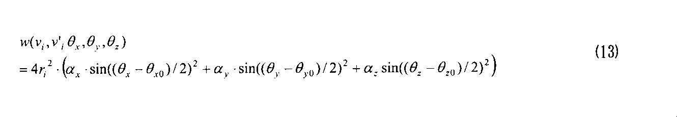
- the weight term is expressed by the following equation in consideration that all rotational movement components are included, for example. Note that r i is the distance from the center of the first image to the feature point v i .
- the coefficients ⁇ x , ⁇ y , and ⁇ z are positive real numbers less than 1 (that is, 0 ⁇ x , ⁇ y , ⁇ z ⁇ 1), respectively. Also, the coefficients ⁇ x , ⁇ y , ⁇ z may be set to different values. As the values of these coefficients are larger, the weight term due to the rotational movement component of the planar projective transformation corresponding to the coefficient is larger, and as a result, the evaluation value C is larger.
- the coefficient ⁇ y may be set to a value smaller than the other coefficients ⁇ x and ⁇ z so that the vertical rotation component in the planar projective transformation coefficient is increased.
- the weight term may be expressed by the following equation.
- the stereo image generating apparatus 1 receives information about the direction of the optical axis of each camera via the image acquisition unit 11, for example. Can be obtained from.
- the parameter determination unit 15 can calculate the difference between the optical axis directions of the respective cameras as an estimated value of the rotation amount of the optical axis of the camera 10-2 with respect to the optical axis of the camera 10-1. Therefore, in such a case, the weight term may be defined as the following equation using the estimated value of the rotation amount.
- ⁇ x0 , ⁇ y0 , and ⁇ z0 are estimated values of the rotation amount of the optical axis of the camera 10-2 with respect to the optical axis of the camera 10-1 around the x axis, the y axis, and the z axis, respectively. .
- the evaluation value calculation unit 151 calculates the evaluation value C according to the expression (6) using the planar projective transformation coefficient corrected by the conversion parameter correction unit 153 until the evaluation value is determined to be converged by the determination unit 152 described later. .
- the evaluation value calculation unit 151 may calculate a differential value C ′ of the evaluation value C instead of the evaluation value C itself. In this case, the evaluation value calculation unit 151 calculates a primary partial differential value obtained by partial differentiation of the right side of the equation (6) with respect to each plane projective transformation coefficient. Then, the evaluation value calculation unit 151 sets the value having the maximum absolute value among the primary partial differential values for each plane projective transformation coefficient as the differential value C ′.
- the evaluation value calculation unit 151 passes the calculated evaluation value C or the differential value C ′ of the evaluation value C and the plane projective transformation coefficient used for calculating the evaluation value C and the like to the determination unit 152.
- the determination unit 152 determines whether or not the evaluation value C calculated by the evaluation value calculation unit 151 or its differential value C ′ satisfies the convergence condition. For example, when the evaluation value C is less than the predetermined threshold value Thc, the determination unit 152 determines that the evaluation value C satisfies the convergence condition and the evaluation value C is minimized.
- the predetermined threshold Thc is set to 0.1, for example.
- the determination unit 152 determines that the differential value C ′ satisfies the convergence condition and the evaluation value C is minimized.
- the predetermined threshold Thd is set to 0.000001, for example.
- the determination unit 152 outputs the planar projective transformation coefficient to the stereoscopic effect adjusting unit 16.
- the determination unit 152 converts the plane projection conversion coefficient used for calculating the evaluation value C and the like into a conversion parameter correction unit to search for a plane projection conversion coefficient suitable for plane projection conversion of the first image. Pass to 153.
- the conversion parameter correction unit 153 corrects the value of at least one plane projection conversion coefficient.
- the conversion parameter correction unit 153 corrects all the planar projection conversion coefficients according to the following equation so that the evaluation value C decreases.
- the partial differential ⁇ C / ⁇ q j is calculated by partial differentiation of the right side of the equation (6) with respect to the planar projective transformation coefficient q j .
- the coefficient ⁇ is set to 0.2, for example.
- the value of partial differential ⁇ C / ⁇ q j may be calculated numerically. Note that the conversion parameter correction unit 153 may correct only one coefficient in one correction.
- the conversion parameter correction unit 153 may correct only the planar projective transformation coefficient that maximizes the absolute value of the partial differential value of the evaluation value C in the equation (14). Alternatively, the conversion parameter correction unit 153 may correct each planar projection conversion coefficient one by one in a predetermined order. The conversion parameter correction unit 153 passes the corrected plane projection conversion coefficient to the evaluation value calculation unit 151.
- the parameter determination unit 15 corrects the planar projective transformation coefficient until the evaluation value C or its differential value C ′ satisfies the convergence condition. Therefore, the parameter determination unit 15 can obtain a plane projective transformation coefficient corresponding to the minimized evaluation value C. Further, as expressed by the equations (6) and (11) to (13), the calculation formula for the evaluation value C includes a weight term that becomes heavier as the rotational movement component increases. Therefore, the evaluation value C for the planar projective transformation coefficient including a coefficient representing a rotational movement component larger than the rotation amount between the optical axes of the two cameras is not minimized. On the other hand, the value of the weight term is smaller than the moving amount of the feature point due to the rotational movement component.
- the parameter determination unit 15 can obtain an appropriate planar projective transformation coefficient by minimizing the evaluation value C.
- the parameter determination unit 15 may obtain a planar projective transformation coefficient that minimizes the evaluation value using a wide-area optimization method such as simulated annealing or a genetic algorithm. Also in this case, the evaluation value is set so as to have a weight term expressed by the equations (11) to (13).
- the stereoscopic effect adjusting unit 16 converts the parallax corresponding to a desired position in the depth direction to reproduce the image on the stereo image created based on the two images acquired via the image acquiring unit 11 into the two images.
- the planar projective transformation coefficient is corrected as given. For example, in a three-dimensional display using binocular parallax, the image in the right-eye image and the image in the left-eye image are only the parallax when the image is located at a predetermined distance from the observer. Created so that the viewing direction is different. Since the left and right eyes of the person are separated in the horizontal direction, the parallax need only have a horizontal component.
- the stereoscopic effect adjusting unit 16 modifies the coefficient t x representing the horizontal translation amount among the plane projective transformation coefficients received from the parameter determining unit 15 according to the parallax.
- the parallax is set in advance and stored in the storage unit 12, for example.
- the stereo image generation device 1 may acquire parallax via a user interface such as a keyboard (not shown).
- FIG. 3 is a diagram illustrating the relationship between the parallax set for two images and the reproduction position in the depth direction of the images on the two images.
- the image 300 is an image for the left eye, and is created, for example, by subjecting the first image created by the camera 10-1 to plane projective transformation.
- the image 310 is an image for the right eye, for example, the second image itself created by the camera 10-2.
- a point 301 on the image 300 and a point 311 on the image 310 represent the same point on the image of the same object.
- the three-dimensional image by the point 301 and the point 311 is reproduced at a position where the line of sight 302 connecting the point 301 and the left eye of the observer intersects with the line of sight 312 connecting the point 311 and the right eye of the observer. Therefore, as the point 301 moves to the right with respect to the point 311, the three-dimensional image of the point 301 and the point 311 is reproduced closer to the observer. Conversely, as the distance between the point 311 and the point 301 is shorter, the three-dimensional image by the point 301 and the point 311 is reproduced near the display on which the images 300 and 310 are displayed. When the line of sight 302 and the line of sight 312 intersect at a position farther than the display on which the images 300 and 310 are displayed, the three-dimensional image of the point 301 and the point 311 is reproduced on the back side of the display.
- the stereoscopic effect adjusting unit 16 corresponds to the ratio of the distance from the observer to the position where the three-dimensional image is reproduced with respect to the distance between the left and right eyes of a general person corresponding to the same object on the two images. It is made equal to the ratio of the distance from the display to the position where the 3D image is reproduced with respect to the distance between them.
- the stereoscopic effect adjusting unit 16 sets a horizontal movement amount s x corresponding to the parallax so as to satisfy this condition.
- the stereoscopic effect adjusting unit 16 calculates a 3 ⁇ 3 matrix H from the parameters obtained by the parameter determining unit 15, the rotation matrix R, and the parallel progression column T, using Equation (1), and the element of the i row and j column of the matrix H is represented by h.
- the stereoscopic effect adjusting unit 16 outputs the planar projective transformation coefficient modified according to the parallax to the converting unit 17.
- the stereoscopic effect adjusting unit 16 may specify the range of such a region according to the parallax.
- the stereoscopic effect adjusting unit 16 outputs information representing the range of the region to the converting unit 17.
- the conversion unit 17 creates a stereo image by performing planar projective transformation of one image using the obtained planar projective transformation coefficient.
- the planar projective transformation coefficient for the first image created by the camera 10-1 is obtained. Therefore, the conversion unit 17 reads the first image from the storage unit 12, and performs plane projective conversion on each pixel of the first image using the plane projection conversion coefficient.
- the conversion unit 17 performs linear interpolation using, for example, the value of the converted pixel positioned around the pixel for each pixel of the converted image. Thus, the value of each pixel after conversion is obtained.
- the conversion unit 17 receives from the stereoscopic effect adjustment unit 16 information on a range of an area where an image is projected only on one eye, the value of each pixel in the range may be set to “0”.
- the conversion unit 17 outputs a set of the first image obtained by plane projection conversion and the second image read from the storage unit 12 to the output unit 18 as a stereo image.
- the output unit 18 includes, for example, an interface circuit for connecting the stereo image generation device 1 to another device. Note that the output unit 18 may add header information in a predetermined format to the stereo image.
- the header information includes information such as the parallax and the sizes of the first and second images, for example. Then, the output unit 18 outputs the created stereo image to another device.
- FIG. 4 is an operation flowchart of the stereo image generation process.
- the stereo image generating apparatus 1 acquires a first image from the camera 10-1 placed at the first point via the image acquisition unit 11, and places it at a second point different from the first point.
- a second image is acquired from the camera 10-2 (step S101).
- the first and second images are stored in the storage unit 12.
- the first image is passed to the feature point extraction unit 13.
- the second image is passed to the tracking unit 14.
- the feature point extraction unit 13 extracts feature points from the first image (step S102).
- the feature point extraction unit 13 outputs information representing the feature points of the image to the tracking unit 14.
- the tracking unit 14 determines a set of corresponding feature points between the first image and the second image using the tracking process (step S103).
- the tracking unit 14 outputs information representing a set of corresponding feature points to the parameter determination unit 15.
- the parameter determination unit 15 initializes the planar projective transformation coefficient (step S104). For example, with this initialization, the coefficients ⁇ x , ⁇ y , ⁇ z , t x , t y , and t z are set to 0, respectively. Then, the parameter determination unit 15 passes the initialized planar projective transformation coefficient to the evaluation value calculation unit 151 of the parameter determination unit 15. The evaluation value calculation unit 151 rotates and moves the sum of the distance between the position where each feature point of the first image is plane-projected using the plane projection conversion coefficient and the position of the corresponding point on the second image. An evaluation value C that is the sum of the weight terms according to the amount is calculated (step S105).
- the evaluation value calculation unit 151 passes the evaluation value C and the plane projective transformation coefficient used for calculation of the evaluation value C to the determination unit 152 of the parameter determination unit 15.
- the determination unit 152 determines whether or not the evaluation value C is less than a predetermined threshold value Thc (step S106). When the evaluation value C is equal to or greater than the predetermined threshold value Thc (No in step S106), the determination unit 152 passes the plane projection conversion coefficient used for calculating the evaluation value C to the conversion parameter correction unit 153 of the parameter determination unit 15.
- the conversion parameter correction unit 153 corrects the planar projection conversion coefficient (step S107). Then, the conversion parameter correction unit 153 passes the corrected plane projection conversion coefficient to the evaluation value calculation unit 151. Then, the parameter determination unit 15 repeats the processes after step S105.
- the determination unit 152 outputs the planar projection conversion coefficient used for calculating the evaluation value C to the stereoscopic effect adjustment unit 16. Then, the stereoscopic effect adjusting unit 16 corrects the planar projective transformation coefficient so as to give a parallax corresponding to the target image reproduction position (step S108). The stereoscopic effect adjusting unit 16 outputs the corrected planar projection conversion coefficient to the converting unit 17.
- the conversion unit 17 reads the first and second images from the storage unit 12.
- the conversion unit 17 creates a stereo image by performing the planar projective transformation on the first image using the planar projective transformation coefficient received from the stereoscopic effect adjusting unit 16 (step S109). Then, the conversion unit 17 outputs the stereo image to another device via the output unit 18. Thereafter, the stereo image generating apparatus 1 ends the stereo image generating process.
- the evaluation value calculation unit 151 may calculate the differential value C ′ of the evaluation value C as described above. In this case, in step S106, if the absolute value of the differential value C ′ is less than the threshold value Thd for the differential value of the evaluation value, the determination unit 152 satisfies the convergence condition, and the evaluation value C is the minimum value. It is determined that
- this stereo image generation apparatus limits the planar projective transformation coefficient to a coefficient representing a rotational movement component and a coefficient representing a parallel movement component that are assumed as actual camera movements. Further, this stereo image generating apparatus has a feature point extracted from one image and subjected to plane projective transformation, a positional deviation amount between corresponding points extracted from the other image, and a weight that increases in accordance with a rotational movement component. Each plane projective transformation coefficient is obtained so as to minimize an evaluation value having a term. Thereby, if the plane projection conversion coefficient includes a coefficient corresponding to a rotational movement component larger than the actual rotation amount between the optical axes of the two cameras, the evaluation value becomes relatively large and is not minimized. Therefore, the stereo image generating apparatus can suppress the need for a plane projective transformation coefficient having a rotational movement component larger than the actual amount of rotation between the optical axes. Therefore, this stereo image generation apparatus can create a stereo image with little image distortion.
- the stereo image generating device may be configured so that the image of the shooting target in the second image matches the image of the shooting target in the first image.
- the second image may be subjected to planar projective transformation.
- the stereo image generating apparatus obtains a planar projective transformation coefficient for the second image.
- the feature point extraction unit may extract feature points from the second image.
- the tracking unit detects a point on the first image corresponding to the feature point extracted from the second image.
- the stereo image generation device may receive a moving image from each camera and create a stereo image for each frame.
- the stereo image generating apparatus creates a planar projective transformation coefficient when the first frame is received from each camera and when at least one of the cameras moves.
- FIG. 5 is a schematic configuration diagram of a stereo image generating apparatus according to this modification.
- the stereo image generating apparatus 2 according to this modification includes an image acquisition unit 11, a storage unit 12, a feature point extraction unit 13, a tracking unit 14, a parameter determination unit 15, a stereoscopic effect adjustment unit 16, and a conversion unit 17. And an output unit 18 and an inter-frame difference unit 19.
- the stereo image generation device 2 is different from the stereo image generation device 1 according to the above-described embodiment shown in FIG. Therefore, in the following, points relating to the inter-frame difference unit 19 will be described. For other components, refer to the related description of the above embodiment.
- the stereo image generating apparatus 2 When the stereo image generating apparatus 2 receives the first frame from each camera, the stereo image generating apparatus 2 calculates a planar projective transformation coefficient. Then, the stereo image generation device 2 stores the plane projective transformation coefficient in the storage unit 12. In addition, the stereo image generation device 2 temporarily stores the frame in the storage unit 12 every time a frame is received from each camera. The storage unit 12 stores the latest several frames for each moving image of each camera.
- the inter-frame difference unit 19 determines, for each moving image of each camera, whether or not the camera has moved by examining changes in pixel values between the latest frame and the previous frame. For this purpose, the inter-frame difference unit 19 performs an inter-frame difference between the latest frame and the previous frame, and obtains a difference value representing a change in pixel value in the time direction for each pixel. The inter-frame difference unit 19 determines that the camera has moved when the number of pixels whose absolute value of the difference value is equal to or greater than a predetermined threshold is equal to or greater than a predetermined ratio with respect to the number of pixels of the entire image.
- the threshold for the absolute value of the difference value is set to, for example, a value of about 1/4 to 1/2 of the range of values that the luminance value can take.
- the predetermined ratio is set to a value of about 40% to 70%, for example.
- the stereo image generation device 2 When the inter-frame difference unit 19 determines that any one of the cameras has moved, the stereo image generation device 2 newly calculates a plane projection conversion coefficient, and calculates the plane projection conversion coefficient stored in the storage unit 12. The newly calculated plane projective transformation coefficient is updated. Then, the conversion unit 17 generates a stereo image by performing plane projection conversion on the frame of one camera using the newly calculated plane projection coefficient. On the other hand, when the inter-frame difference unit 19 determines that no camera has moved, the conversion unit 17 uses one of the plane projection conversion coefficients stored in the storage unit 12 and created in the past. A stereo image is generated by plane projective transformation of the frame. In this case, the processing of the feature point extraction unit 13, the tracking unit 14, the parameter determination unit 15, and the stereoscopic effect adjustment unit 16 is omitted.
- the stereo image generation device may generate a stereo image based on two images received from one camera.
- the stereo image generating device receives the first image via the image acquisition unit. .
- the stereo image generation device stores the first image in the storage unit.
- the stereo image generating device passes through the image acquisition unit.
- the second image is received.
- the stereo image generating apparatus receives both the first and second images, the stereo image generating apparatus obtains a planar projective transformation coefficient according to the above embodiment.
- the stereo image generating apparatus creates a stereo image by performing planar projective transformation on one of the first and second images using the planar projective transformation coefficient.
- the stereo image generation device may receive a third image captured by the camera at at least one point between the first point and the second point. Then, the feature point extraction unit of the stereo image generation device extracts the feature points from the first image. The tracking unit obtains a set of corresponding feature points between the first image and the third image, and obtains a set of corresponding feature points between the third image and the second image. The feature points extracted from the second image corresponding to the feature points extracted from the first image may be specified.
- a computer program that causes a computer to realize the functions of the feature point extraction unit, the tracking unit, the parameter determination unit, the stereoscopic effect adjustment unit, and the conversion unit included in the stereo image generation device is recorded in a computer-readable medium. May be provided.
Landscapes
- Engineering & Computer Science (AREA)
- Multimedia (AREA)
- Signal Processing (AREA)
- Computer Vision & Pattern Recognition (AREA)
- Physics & Mathematics (AREA)
- General Physics & Mathematics (AREA)
- Theoretical Computer Science (AREA)
- Image Processing (AREA)
- Studio Devices (AREA)
- Testing, Inspecting, Measuring Of Stereoscopic Televisions And Televisions (AREA)
Abstract
ステレオ画像生成装置は、第1の地点で撮影された第1の画像から複数の特徴点を抽出する特徴点抽出部と、第2の地点で撮影された第2の画像から、第1の画像の複数の特徴点と撮影対象物の同一の点として対応する点の座標を算出するトラッキング部と、第1の画像の特徴点を、回転移動成分を表す係数と平行移動成分を表す係数とを含む平面射影変換係数を用いて平面射影変換することにより得られた変換特徴点と、第1の画像の特徴点に対応する第2の画像の点との間の距離の差と、回転移動成分に応じた値を持つ重み項とを含む評価値を最小化するように、平面射影変換係数を決定するパラメータ決定部と、平面射影変換パラメータを用いて第1の画像を平面射影変換し、その平面射影変換された画像と第2の画像との組をステレオ画像として生成する変換部とを有する。
Description
本発明は、例えば、同じ物体を異なる方向から撮影した2枚の画像に基づいてステレオ画像を生成するステレオ画像生成装置、ステレオ画像生成方法及びステレオ画像生成用コンピュータプログラムに関する。
従来より、3次元的な像を再生するための研究がなされている。3次元的な像を再生するための一つの方法として、同一の物体に対して異なる方向から撮影した二つの画像を並べて表示し、その二つの画像のそれぞれを、観察者の左右それぞれの眼に見せる方法が知られている。このような方法で用いられる2枚一組の画像は、ステレオ画像と呼ばれる。
ステレオ画像を作成するために、例えば、1台のカメラを用いて第1の地点において対象物体を撮影することにより第1の画像が作成され、その後、そのカメラを第2の地点に移動させて対象物体を撮影することにより第2の画像が作成される。あるいは、第1の地点及び第2の地点に配置された2台のカメラにより対象物体を撮影することにより、第1の画像及び第2の画像が作成される。そしてこの第1の画像と第2の画像が、一組のステレオ画像となる。
ステレオ画像に含まれる2枚の画像は、観察者の左右それぞれの眼で観察されるものであるため、質のよい3次元像を再生するために、その2枚の画像に写された像は、観察者が一般的に物を見る条件と同じ条件で撮影されていることが好ましい。人間の左右の眼は、水平方向に並んでいるため、第1の地点と第2の地点も水平に並んでいることが好ましい。また左右の眼のそれぞれの視線は略平行であるため、第1の地点におけるカメラの光軸と第2の地点におけるカメラの光軸は互いに平行であることが好ましい。
第1の地点及び第2の地点において、カメラをこのように正確に配置するためには、撮影者は、厳密なアライメント調整を行わねばならない。そこで、第1の地点及び第2の地点におけるカメラの位置及び姿勢が測定され、その測定結果に応じてカメラの配置が調節される。このような厳密なアライメント調整を行うためには、例えば、作業者は、測量用の計測器を用いて測量したり、その結果に応じてカメラの位置調整のための様々な手作業を行うことになる。そのため、ステレオ画像を作成するために、多大なコスト及び作業時間が必要となる。したがって、実際には、このような厳密なアライメント調整を行うことは困難なことが多い。その結果として、第1の地点におけるカメラの高さが第2の地点におけるカメラの高さと異なったり、第1の地点におけるカメラの光軸方向が第2の地点におけるカメラの光軸方向と異なったり、あるいは一方の画像が他方の画像に対して光軸回りに回転してしまう。
そこで、画像上の像の位置を変換することにより、ステレオ画像に適した画像を作成する技術が提案されている(例えば、特許文献1及び非特許文献1を参照)。このような技術では、撮影時における二つの地点でのカメラの高さ、光軸方向の差及び光軸回りの回転のずれを補正するように、カメラの焦点距離及び歪曲収差といったカメラの特性を考慮して画像上の像の位置が変換される。
そのような公知技術の一例による画像処理装置は、2枚の画像のそれぞれから抽出された、対応する特徴点同士が一致するように平面射影変換の回転式または回転並進式を決定する。そしてその画像処理装置は、回転式または回転並進式を用いて画像上の各点を位置変換することで、ステレオ画像を生成する。
そのような公知技術の一例による画像処理装置は、2枚の画像のそれぞれから抽出された、対応する特徴点同士が一致するように平面射影変換の回転式または回転並進式を決定する。そしてその画像処理装置は、回転式または回転並進式を用いて画像上の各点を位置変換することで、ステレオ画像を生成する。
また、他の公知技術による画像処理装置は、エピポーラ幾何を考慮して画像を変換することでステレオ画像を生成する。エピポーラ幾何は、撮影対象物体上の一つの注目点を互いに異なる二つの撮影位置から撮影した場合の、画像上での注目点と各撮影位置との幾何学的な対応関係を表すものである。具体的には、第1の位置に配置されたカメラと注目点とを結ぶ線は、第2の位置に配置されたカメラにより撮影された画像上に投影された直線となる。同様に、第2の位置に配置されたカメラと注目点とを結ぶ線は、第1の位置に配置されたカメラにより撮影された画像上に投影された直線となる。なお、この画像上に投影された直線はエピ極線と呼ばれる。エピポーラ幾何を利用する装置は、このような対応関係を考慮して、エピ極線を平行化する平面射影変換係数を求めて少なくとも一方の画像を変換することにより、カメラの光軸が平行な状態で撮影された2枚の画像の組を擬似的に作成できる。
Richard I. Hartley.、"Theory and practice of projective rectification"、International Journal of Computer Vision、1999年11月、第35巻、第2号、p.115-127
エピポーラ幾何を利用する技術では、注目点に対応する各画像上での特徴点が正確に求められていないと、その特徴点の抽出誤差による影響のため、正確な平面射影変換係数が算出されないおそれがあった。またこの技術では、カメラが有する撮像光学系の歪曲収差などによる画像の歪みによっても、平面射影変換係数が正確に算出されないおそれがあった。
また、2枚の画像間の対応する特徴点が一致するように回転式または回転並進式の係数を求める技術では、複数の対応する特徴点の組全体に対して位置の誤差が最小化される。そのため、この技術は、複数の特徴点の組の一部に、特徴点の対応付けを誤った特徴点の組が含まれている場合でも、比較的正確な係数を求めることができる。
しかしながら、撮影対象物が奥行きを持っている場合、視差により、撮影対象物の手前側に位置する点に対応する2枚の画像から抽出された特徴点間の距離は、撮影対象物の奥側に位置する点に対応する2枚の画像から抽出された特徴点間の距離より大きくなる。そのため、2枚の画像の対応する特徴点の組が一致するように、画像上の像の位置を正確に変換するためには、本来、画像上の各点を、その点における撮影対象物体までの距離に応じて移動量を調整する非線形な位置変換が必要となる。
一方、回転式または回転並進式により行われる位置変換は、直線を他の直線に変換するような線形変換である。そのため、撮影対象物が奥行きを持つ場合、その撮影対象物上の特徴点に基づいて決定された平面射影変換係数を用いて変換された画像では、撮影対象物の像がその変換によって歪んでしまうことがあった。
そこで、本明細書は、平面射影変換によって生じる画像に写っている像の歪みを抑制できるステレオ画像生成装置、ステレオ画像生成方法及びステレオ画像生成用コンピュータプログラムを提供することを目的とする。
一つの実施形態によれば、ステレオ画像生成装置が提供される。このステレオ画像生成装置は、第1の地点で撮影対象物を撮影した第1の画像から複数の特徴点を抽出する特徴点抽出部と、第1の地点と異なる第2の地点で撮影対象物を撮影した第2の画像から、第1の画像から抽出された複数の特徴点と撮影対象物上の同一の点として対応する点の座標を算出するトラッキング部と、第1の画像の特徴点を回転移動成分を表す係数と平行移動成分を表す係数とを含む平面射影変換係数を用いて平面射影変換することにより得られた変換特徴点と第1の画像の特徴点に対応する第2の画像の点との間の距離の差と、回転移動成分に応じた値を持つ重み項とを含む評価値を最小化するように、平面射影変換係数を決定するパラメータ決定部と、平面射影変換パラメータを用いて第1の画像を平面射影変換し、その平面射影変換された画像と第2の画像との組をステレオ画像として生成する変換部とを有する。
また、他の実施形態によれば、ステレオ画像生成方法が提供される。このステレオ画像生成方法は、第1の地点で撮影対象物を撮影した第1の画像から複数の特徴点を抽出し、第1の地点と異なる第2の地点で撮影対象物を撮影した第2の画像から、第1の画像から抽出された複数の特徴点と撮影対象物上の同一の点として対応する点の座標を算出し、第1の画像の特徴点を回転移動成分と平行移動成分とからなる平面射影変換係数を用いて平面射影変換することにより得られた変換特徴点と第1の画像の特徴点に対応する第2の画像の点との間の距離の差と、回転移動成分に応じた値を持つ重み項とを含む評価値を最小化するように平面射影変換係数を決定し、平面射影変換パラメータを用いて第1の画像を平面射影変換し、平面射影変換された画像と第2の画像との組をステレオ画像として生成することを含む。
さらに他の実施形態によれば、ステレオ画像をコンピュータに生成させるコンピュータプログラムが提供される。このコンピュータプログラムは、第1の地点で撮影対象物を撮影した第1の画像から複数の特徴点を抽出し、第1の地点と異なる第2の地点で撮影対象物を撮影した第2の画像から、第1の画像から抽出された複数の特徴点と撮影対象物上の同一の点として対応する点の座標を算出し、第1の画像の特徴点を回転移動成分と平行移動成分とからなる平面射影変換係数を用いて平面射影変換することにより得られた変換特徴点と第1の画像の特徴点に対応する第2の画像の点との間の距離の差と、回転移動成分に応じた値を持つ重み項とを含む評価値を最小化するように平面射影変換係数を決定し、平面射影変換パラメータを用いて第1の画像を平面射影変換し、平面射影変換された画像と第2の画像との組をステレオ画像として生成することをコンピュータに実行させる命令を有する。
本発明の目的及び利点は、請求項において特に指摘されたエレメント及び組み合わせにより実現され、かつ達成される。
上記の一般的な記述及び下記の詳細な記述の何れも、例示的かつ説明的なものであり、請求項のように、本発明を制限するものではないことを理解されたい。
上記の一般的な記述及び下記の詳細な記述の何れも、例示的かつ説明的なものであり、請求項のように、本発明を制限するものではないことを理解されたい。
ここに開示されるステレオ画像生成装置、ステレオ画像生成方法及びステレオ画像生成用コンピュータプログラムは、平面射影変換によって生じる画像に写っている像の歪みを抑制できる。
最初に、従来技術により決定された平面射影変換係数を用いて生成されたステレオ画像の問題点について、例を挙げて説明する。
図1(A)は、互いに異なる二つの地点において、光軸が平行となるように配置された2台のカメラを用いて撮影された2枚の画像に写った像の例を示す図である。第1の画像100及び第2の画像110の何れにも、同一の物体101が写っている。そしてこの物体101は奥行きを有する。第1の画像100及び第2の画像110のそれぞれにおいて、平面射影変換係数を求めるために、物体101の4個のコーナー102a~105a、102b~105bが、それぞれ特徴点として抽出されている。そして特徴点の組(102a、102b)、(103a、103b)、(104a、104b)及び(105a、105b)が、それぞれ、物体101の同一の点に対応する。このうち、特徴点の組(102a、102b)、(103a、103b)に対応する物体101のコーナーは、手前側に位置し、一方、特徴点の組(104a、104b)、(105a、105b)に対応する物体101のコーナーは、奥側に位置する。そのため、第1の画像100の上の各特徴点を基準として、第2の画像110において、手前側のコーナーに対応する特徴点102b及び103bは、奥側のコーナーに対応する特徴点104b及び105bよりも相対的に大きく左方向に移動している。そして画像上では、特徴点の組(102a、102b)、(103a、103b)よりも、特徴点の組(104a、104b)、(105a、105b)の方が上側に位置している。その結果、二つの画像100、110間の特徴点間の位置ずれを最小化する平面射影変換には、画像を時計回りに回転させる回転移動成分が含まれる。
図1(A)は、互いに異なる二つの地点において、光軸が平行となるように配置された2台のカメラを用いて撮影された2枚の画像に写った像の例を示す図である。第1の画像100及び第2の画像110の何れにも、同一の物体101が写っている。そしてこの物体101は奥行きを有する。第1の画像100及び第2の画像110のそれぞれにおいて、平面射影変換係数を求めるために、物体101の4個のコーナー102a~105a、102b~105bが、それぞれ特徴点として抽出されている。そして特徴点の組(102a、102b)、(103a、103b)、(104a、104b)及び(105a、105b)が、それぞれ、物体101の同一の点に対応する。このうち、特徴点の組(102a、102b)、(103a、103b)に対応する物体101のコーナーは、手前側に位置し、一方、特徴点の組(104a、104b)、(105a、105b)に対応する物体101のコーナーは、奥側に位置する。そのため、第1の画像100の上の各特徴点を基準として、第2の画像110において、手前側のコーナーに対応する特徴点102b及び103bは、奥側のコーナーに対応する特徴点104b及び105bよりも相対的に大きく左方向に移動している。そして画像上では、特徴点の組(102a、102b)、(103a、103b)よりも、特徴点の組(104a、104b)、(105a、105b)の方が上側に位置している。その結果、二つの画像100、110間の特徴点間の位置ずれを最小化する平面射影変換には、画像を時計回りに回転させる回転移動成分が含まれる。
図1(B)は、従来技術により決定された平面射影変換係数を用いて、図1(A)に示された第1の画像100を平面射影変換することにより得られた変換画像120を表す図である。この変換画像120では、二つの地点間でカメラの光軸が平行であるにもかかわらず、平面射影変換係数が回転移動成分を含んでいるため、回転中心から離れた画像上の点ほど、本来とは異なる回転が加えられることになる。その結果、例えば、変換画像120では、物体101の左前方の下側のコーナー106が、本来の位置よりも左側に移動してしまい、本来、画像上で垂直となるべき物体101の左前方のエッジ107が斜めを向いてしまう。このように、一方の撮影地点におけるカメラの向きに対する他方の撮影地点におけるカメラの向きの回転量よりも大きい回転移動成分が平面射影変換に含まれると、その平面射影変換係数を用いて変換された画像の歪みが顕著になってしまうおそれがある。
そこで、一つの実施形態による、ステレオ画像生成装置は、ステレオ画像を生成するために、異なる地点で撮影対象物を撮影して得られた2枚の画像の少なくとも一方を平面射影変換する平面射影変換係数を求める。そしてこのステレオ画像生成装置は、平面射影変換係数が回転移動成分と平行移動成分を表す係数のみを含み、その回転移動成分が、一方の撮影地点でのカメラの光軸と他方の撮影地点でのカメラの光軸との間の回転量以下となるように平面射影変換係数を決定する。これにより、このステレオ画像生成装置は、平面射影変換による画像の歪みを抑制する。
図2は、一つの実施形態によるステレオ画像生成装置の概略構成図である。ステレオ画像生成装置1は、画像取得部11と、記憶部12と、特徴点抽出部13と、トラッキング部14と、パラメータ決定部15と、立体感調節部16と、変換部17と、出力部18とを有する。
ステレオ画像生成装置1の各部は、それぞれ別個の回路として形成される。あるいはステレオ画像生成装置1の各部は、その各部に対応する回路が集積された一つの集積回路としてステレオ画像生成装置1に実装されてもよい。さらに、ステレオ画像生成装置1は、1個以上のプロセッサとメモリ回路とを有してもよい。この場合、特徴点抽出部13、トラッキング部14、パラメータ決定部15、立体感調節部16及び変換部17は、ステレオ画像生成装置1が有するプロセッサ上で実行されるコンピュータプログラムにより実現される、機能モジュールであってもよい。
画像取得部11は、第1の地点に置かれたカメラ10-1と第1の地点と異なる第2の地点に置かれたカメラ10-2から、それぞれ、同一の撮影対象物を撮影して得られた画像を取得する。そのために、画像取得部11は、例えば、カメラ10-1及び10-2とステレオ画像生成装置1とを接続するためのユニバーサル・シリアル・バス(Universal Serial Bus、USB)などのシリアルバス規格に従ったインターフェース回路を有する。あるいは、画像取得部11は、カメラ10-1及び10-2により生成された2枚の画像を記憶しているサーバなどの他の装置とステレオ画像生成装置1とを通信ネットワークを介して接続するためのインターフェース回路を有していてもよい。
画像取得部11は、取得した2枚の画像を記憶部12に保存する。また画像取得部11は、取得した2枚の画像のうち、カメラ10-1から取得した画像を特徴点抽出部13へ出力する。さらに画像取得部11は、カメラ10-2から取得した画像をトラッキング部14へ出力する。なお、以下では、便宜上、カメラ10-1により作成された画像を第1の画像と呼び、カメラ10-2により作成された画像を第2の画像と呼ぶ。
画像取得部11は、取得した2枚の画像を記憶部12に保存する。また画像取得部11は、取得した2枚の画像のうち、カメラ10-1から取得した画像を特徴点抽出部13へ出力する。さらに画像取得部11は、カメラ10-2から取得した画像をトラッキング部14へ出力する。なお、以下では、便宜上、カメラ10-1により作成された画像を第1の画像と呼び、カメラ10-2により作成された画像を第2の画像と呼ぶ。
記憶部12は、例えば、読み書き可能な揮発性または不揮発性の半導体メモリ回路、あるいは、磁気記録媒体または光記録媒体を有する。そして記憶部12は、画像取得部11から受け取った第1及び第2の画像を記憶する。またステレオ画像生成装置1が有する各部の少なくとも何れかが、ステレオ画像生成装置1が有するプロセッサ上で実行されるコンピュータプログラムにより実現される場合、そのコンピュータプログラムを記憶してもよい。
特徴点抽出部13は、第1の画像から、各画像に写っている像の特徴的な点を特徴点として抽出する。
例えば、特徴点抽出部13は、第1の画像に対して、HarrisオペレータまたはFoerstnerオペレータといったコーナー検出フィルタを用いたフィルタリング処理を行って、コーナー状の特徴を有する点を特徴点として抽出する。なお、第1の画像がカラー画像である場合、特徴点抽出部13は、第1の画像の画素の値を例えばHSV表色系の値に変換し、明度を表す画素値に対して、フィルタリング処理を行ってもよい。
あるいは、特徴点抽出部13は、特徴点として、その他の特徴的な点、例えば、周囲の画素の値よりも高いまたは低い画素値を持つ画素を、第1の画像とそのような特徴点に相当するテンプレートとの間でテンプレートマッチングを行って抽出してもよい。
特徴点抽出部13は、画像ごとに、複数の特徴点を表す情報を生成する。複数の特徴点を表す情報は、例えば、各特徴点の位置を含む。あるいは複数の特徴点を表す情報は、各特徴点の特性、例えば、特徴点の画素値、コーナーの向きなどを含んでいてもよい。そして特徴点抽出部13は、その情報をトラッキング部14へ出力する。
トラッキング部14は、第1の画像から抽出された複数の特徴点と、第1の地点とは異なる第2の地点で撮影対象物を撮影した第2の画像から、第2の画像における特徴点として、第1の画像から抽出された複数の特徴点と撮影対象物上の同一の点として対応する点の座標を算出する。トラッキング部14は、そのような対応特徴点の組を少なくとも一つ求める。
本実施形態では、トラッキング部14は、例えば、Kanade Lucas Tomasi Tracker(KLT)法といったトラッキング技術を用いて、第1の画像上の注目する特徴点に対応する第2の画像上の点を特定することにより、対応特徴点の組を求める。あるいは、トラッキング部14は、勾配法またはブロックマッチング法といった、公知の様々なトラッキング法の何れかを用いて対応特徴点の組を求めてもよい。その際、トラッキング部14は、特徴点の特性が類似しているもの同士に限り、対応特徴点の組としてもよい。
トラッキング部14は、対応特徴点の組ごとに、識別子と、その対応特徴点の組に含まれる二つの特徴点の位置などの情報を含む対応特徴点情報を生成する。そしてトラッキング部14は、対応特徴点情報をパラメータ決定部15へ出力する。
パラメータ決定部15は、各画像に写っている同一の撮影対象物の像が一致するように、2枚の画像のうちの一方を平面射影変換するための平面射影変換係数を算出する。そのために、パラメータ決定部15は、評価値算出部151と、判定部152と、変換パラメータ修正部153とを有する。
本実施形態では、ステレオ画像生成装置1は、第1の画像に写っている撮影対象物の像が、第2の画像に写っているその撮影対象物の像と一致するように、第1の画像を平面射影変換する。
本実施形態では、ステレオ画像生成装置1は、第1の画像に写っている撮影対象物の像が、第2の画像に写っているその撮影対象物の像と一致するように、第1の画像を平面射影変換する。
平面射影変換には、一般に、回転移動成分、平行移動成分及びせん断成分が含まれる。しかし、同一の撮影対象物を異なる二つの地点から撮影する場合、その二つの地点間でのカメラの動きは、回転移動成分と平行移動成分のみを含む。従って、パラメータ決定部15は、同一の撮影対象物についての第1の画像上の像と第2の画像上の像を近似的に一致させるために、平面射影変換の回転移動成分と平行移動成分のみを考慮すればよい。そこで、本実施形態では、第1の画像は、次式に従って平面射影変換される。

ここでp1は、第1の画像上の各画素の座標を表すベクトルであり、水平座標をx、垂直座標をyとすると、p1=(x,y,1)tである。またp'1は、平面射影変換後の第1の画像上の各画素の座標を表すベクトルであり、水平座標をx'、垂直座標をy'とすると、p'1=(x',y',1)tである。またRx(θx)、Ry(θy)及びRz(θz)は、それぞれ、カメラ10-1の光軸をz方向とし、x軸、y軸をそれぞれ光軸zに対して直交する平面の水平軸及び垂直軸とした場合のx軸、y軸及びz軸を中心とする回転移動成分を表す行列であり、次式で表される。

なお、θx、θy及びθzは、それぞれ、x軸、y軸及びz軸を中心とする回転移動成分を表す平面射影変換係数である。
また、T(tx,ty,tz)は、平行移動成分を表す並進行列であり、次式で表される。

なお、tx、ty及びtzは、それぞれ、x軸、y軸及びz軸に沿った平行移動成分を表す平面射影変換係数である。
さらに、Nは、カメラ10-1の特性を表す内部パラメータ行列であり、またN-1は、内部パラメータ行列Nの逆行列である。内部パラメータ行列Nは、例えば、次式で表される。

ここでfは、カメラ10-1の焦点距離であり、cx、cyは、光軸上の点に対応する第1の画像上の水平座標及び垂直座標である。なお、カメラ10-1の焦点距離が既知でない場合、焦点距離fとして、例えば、一般的によく使用される画角を持つカメラの焦点距離を用いてもよい。また、カメラ10-1が有するイメージセンサの画素の高さと幅のアスペクト比が1:1でない場合、内部パラメータ行列Nは、例えば、次式に従って表されてもよい。
ここで、fx及びfyは、それぞれ、例えば、カメラ10-1が有する撮像光学系の焦点距離をfとし、画素の幅をW、画素の高さをHとして、fx=f/W、fy=f/Hとすることができる。
また、T(tx,ty,tz)は、平行移動成分を表す並進行列であり、次式で表される。
さらに、Nは、カメラ10-1の特性を表す内部パラメータ行列であり、またN-1は、内部パラメータ行列Nの逆行列である。内部パラメータ行列Nは、例えば、次式で表される。
理想的な平面射影変換係数が求められている場合、第1の画像から抽出された各特徴点が(1)式に従って平面射影変換されると、その変換後の各特徴点の位置は、対応する第2の画像上における第1の画像の特徴点に対応する点の位置となる。
そこで、パラメータ決定部15は、評価値算出部151により、第1の画像から抽出された各特徴点を(1)式に従って平面射影変換した場合に、その変換後の特徴点の位置と対応する第2の画像から抽出された点との間の距離の差を含む評価値を算出する。
さらに、本実施形態では、評価値は、回転移動成分を抑制するために、回転移動成分が増加するにつれて値が大きくなり、かつ、回転移動成分による特徴点の移動量よりも小さい重み項を含む。パラメータ決定部15は、このような評価値を最小化する平面射影変換係数を求める。
そこで、パラメータ決定部15は、評価値算出部151により、第1の画像から抽出された各特徴点を(1)式に従って平面射影変換した場合に、その変換後の特徴点の位置と対応する第2の画像から抽出された点との間の距離の差を含む評価値を算出する。
さらに、本実施形態では、評価値は、回転移動成分を抑制するために、回転移動成分が増加するにつれて値が大きくなり、かつ、回転移動成分による特徴点の移動量よりも小さい重み項を含む。パラメータ決定部15は、このような評価値を最小化する平面射影変換係数を求める。
本実施形態では、評価値Cは次式で表される。

ここで、vi(i=1,2,...,N)は、第1の画像から抽出された特徴点を表し、v'i(i=1,2,...,N)は、特徴点viに対応する第2の画像の点を表す。またNは、1以上の整数であり、対応特徴点の組の数を表す。またノルム||α-β||は、画像上の2点α=(αx, αy, 1)とβ=(βx, βy, 1)間の距離を表し、例えば、||α-β||={(αx-βx)2+(αy-βy)2}1/2である。そしてw(vi, v'i, θx, θy, θz)は、回転移動成分に応じて大きくなる重み項である。なお、(6)式の右辺の第1項は、点v'iと点h(θx, θy, θz, tx, ty, tz)vi間の差の絶対値の総和であってよい。
ここで重み項w(vi, v'i, θx, θy, θz)の設定方法について説明する。カメラ10-2の光軸が、カメラ10-1の光軸(すなわち、z軸)に対して回転角度-Θで回転している場合、第1の画像上の特徴点viは、(1)式に基づき、第2の画像上では次式で表される位置に回転移動すると推定される。

このような回転移動において、回転中心から特徴点viまでの円の半径がri、回転角度がΘである場合、弦に沿った特徴点の移動量は2ri・sin(Θ/2)となる。また光軸上の点は、一般に画像中心に位置するので、回転移動の円の半径riは、画像中心から特徴点viまでの距離となる。
そのため、第1の画像上の特徴点viと第2の画像上の対応する点v'i間の距離の2乗と、特徴点viをz軸を中心に角度Θだけ回転移動させた点と点v'i間の距離の2乗との差は次式で表される。

ここでεiは、抽出された特徴点のずれ、または歪曲収差などにより生じる誤差である。
カメラ10-2の光軸が、カメラ10-1の光軸に対して回転角度-Θで回転している場合、(8)式は、全ての対応特徴点の組について成立する。したがって、次式が成立する。

ここで誤差の項Σεiが十分に小さければ、(9)式から次の条件が仮定される。

ただし、係数αは0<α<1を満たす値を持つ。
そのため、第1の画像上の特徴点viと第2の画像上の対応する点v'i間の距離の2乗と、特徴点viをz軸を中心に角度Θだけ回転移動させた点と点v'i間の距離の2乗との差は次式で表される。
カメラ10-2の光軸が、カメラ10-1の光軸に対して回転角度-Θで回転している場合、(8)式は、全ての対応特徴点の組について成立する。したがって、次式が成立する。
ここで、(10)’式の左辺は、回転移動量及び平行移動量が0である(すなわち、h(0,0,0,0,0,0))場合における、評価値Cを算出する(6)式の右辺の第1項に相当する。したがって、(10)’式は、各特徴点viをz軸の周りに角度Θ回転させたときの対応特徴点間の距離の2乗和と各特徴点viの回転移動量に係数αを乗じた値の総和との合計が小さくなることを示している。すなわち、カメラ10-1の光軸に対してカメラ10-2の光軸がz軸を中心として回転している場合には、適切なΘの値を求めることにより、(10)’式の右辺は、回転移動成分及び平行移動成分がないとしたときの評価値Cよりも小さくなる。一方、カメラ10-1の光軸に対する、カメラ10-2の光軸の移動に、z軸を中心とする回転移動成分が含まれない場合、(10)’式の関係は成立しない。したがって、Θの値だけを調整しても、(10)’式の右辺の値は、回転移動成分及び平行移動成分がないとしたときの評価値Cより小さくならない可能性が高い。
ここで(10)’式の右辺と(6)式の右辺を比較すると、(10)’式の右辺の第1項は(6)式の右辺の第1項と対応することが分かる。そのため、(6)式の右辺の第2項、すなわち、重み項は、(10)’式の右辺の第2項に対応させることができる。
したがって、重み項は、例えば、全ての回転移動成分が含まれることを考慮して、次式で表される。

なお、riは、第1の画像の中心から特徴点viまでの距離である。係数αx、αy、αzは、それぞれ、1未満の正の実数(すなわち、0 < αx、αy、αz < 1)である。また、係数αx、αy、αzは、互いに異なる値に設定されてもよい。そしてこれらの係数の値が大きいほど、その係数に対応する平面射影変換の回転移動成分による重み項が大きくなるので、結果として評価値Cも大きくなる。そのため、係数αx、αy、αzの値が大きいほど、その係数に対応する平面射影変換係数θx、θy、θzは抑制される。例えば、カメラ10-1及びカメラ10-2が設置される際、それらのカメラの光軸は、垂直方向に回転量し易い。そこで、平面射影変換係数における垂直方向の回転成分が大きくなるように、係数αyは、他の係数αx及びαzよりも小さな値に設定されてもよい。
したがって、重み項は、例えば、全ての回転移動成分が含まれることを考慮して、次式で表される。
また、半径rの円周上の2点間の中心角度θが十分に小さい場合、その2点を結ぶ弦の長さは、rθで近似できる。そのため、カメラ10-1の光軸に対する、カメラ10-2の光軸の回転量が小さい場合、重み項は次式で表されてもよい。

また、カメラ10-1及び10-2がジャイロセンサを搭載している場合のように、各カメラの光軸の方向に関する情報を、ステレオ画像生成装置1が例えば画像取得部11を介して各カメラから取得できることがある。このような場合、パラメータ決定部15は、各カメラの光軸の方向間の差を、カメラ10-1の光軸に対する、カメラ10-2の光軸の回転量の推定値として算出できる。そこで、このような場合、重み項は、その回転量の推定値を用いて、次式のように定義されてもよい。
ここでθx0、θy0、θz0は、それぞれ、x軸、y軸、z軸を中心とするカメラ10-1の光軸に対する、カメラ10-2の光軸の回転量の推定値である。
評価値算出部151は、後述する判定部152により評価値が収束すると判定されるまで、変換パラメータ修正部153により修正された平面射影変換係数を用いて(6)式に従って評価値Cを算出する。
あるいは、評価値算出部151は、評価値Cそのものの代わりに、評価値Cの微分値C'を算出してもよい。この場合、評価値算出部151は、(6)式の右辺を各平面射影変換係数について偏微分した1次偏微分値を算出する。そして評価値算出部151は、各平面射影変換係数についての1次偏微分値のうち、絶対値が最大となる値を微分値C'とする。
評価値算出部151は、算出した評価値Cまたは評価値Cの微分値C'と、評価値Cなどの算出に用いた平面射影変換係数とを判定部152へ渡す。
あるいは、評価値算出部151は、評価値Cそのものの代わりに、評価値Cの微分値C'を算出してもよい。この場合、評価値算出部151は、(6)式の右辺を各平面射影変換係数について偏微分した1次偏微分値を算出する。そして評価値算出部151は、各平面射影変換係数についての1次偏微分値のうち、絶対値が最大となる値を微分値C'とする。
評価値算出部151は、算出した評価値Cまたは評価値Cの微分値C'と、評価値Cなどの算出に用いた平面射影変換係数とを判定部152へ渡す。
判定部152は、評価値算出部151により算出された評価値Cまたはその微分値C'が収束条件を満たしたか否か判定する。
例えば、判定部152は、評価値Cが所定の閾値Thc未満となった場合、評価値Cが収束条件を満たし、評価値Cは最小化されたと判定する。なお、所定の閾値Thcは、例えば、0.1に設定される。
あるいは、判定部152は、評価値Cの微分値C'の絶対値が所定の閾値Thd未満である場合、微分値C'が収束条件を満たし、評価値Cが最小化されたと判定する。この場合、所定の閾値Thdは、例えば、0.000001に設定される。
例えば、判定部152は、評価値Cが所定の閾値Thc未満となった場合、評価値Cが収束条件を満たし、評価値Cは最小化されたと判定する。なお、所定の閾値Thcは、例えば、0.1に設定される。
あるいは、判定部152は、評価値Cの微分値C'の絶対値が所定の閾値Thd未満である場合、微分値C'が収束条件を満たし、評価値Cが最小化されたと判定する。この場合、所定の閾値Thdは、例えば、0.000001に設定される。
評価値Cまたはその微分値C'が収束条件を満たした場合、その評価値Cなどを算出するために用いられた平面射影変換係数に基づいて平面射影変換された第1の画像の特徴点は、対応する第2の画像の点と良好に一致する。従って、その平面射影変換係数は、第1の画像を平面射影変換するのに適している。そこで判定部152は、その平面射影変換係数を立体感調節部16へ出力する。
一方、評価値C及びその微分値C'が収束条件を満たさない場合、その評価値Cなどを算出するために用いられた平面射影変換係数に基づいて平面射影変換された第1の画像の特徴点は、対応する第2の画像の点と十分に一致しない。そこで判定部152は、第1の画像を平面射影変換するのに適した平面射影変換係数を探索するために、評価値Cなどを算出するために用いられた平面射影変換係数を変換パラメータ修正部153へ渡す。
一方、評価値C及びその微分値C'が収束条件を満たさない場合、その評価値Cなどを算出するために用いられた平面射影変換係数に基づいて平面射影変換された第1の画像の特徴点は、対応する第2の画像の点と十分に一致しない。そこで判定部152は、第1の画像を平面射影変換するのに適した平面射影変換係数を探索するために、評価値Cなどを算出するために用いられた平面射影変換係数を変換パラメータ修正部153へ渡す。
変換パラメータ修正部153は、評価値C及びその微分値C'が収束条件を満たしていない場合、少なくとも一つの平面射影変換係数の値を修正する。例えば、変換パラメータ修正部153は、評価値Cが減少するように、次式に従って全ての平面射影変換係数を修正する。

ここで偏微分∂C/∂qjは、(6)式の右辺を平面射影変換係数qjについて偏微分することにより算出される。また係数γは、例えば、0.2に設定される。なお、偏微分∂C/∂qjの値は、数値演算的に算出されてもよい。
なお、変換パラメータ修正部153は、1回の修正において、一つの係数のみを修正してもよい。この場合、変換パラメータ修正部153は、例えば、(14)式において評価値Cの偏微分値の項の絶対値がもっとも大きくなる平面射影変換係数のみを修正してもよい。あるいは、変換パラメータ修正部153は、所定の順番に従って、各平面射影変換係数を一つずつ修正してもよい。
変換パラメータ修正部153は、修正された平面射影変換係数を評価値算出部151へ渡す。
なお、変換パラメータ修正部153は、1回の修正において、一つの係数のみを修正してもよい。この場合、変換パラメータ修正部153は、例えば、(14)式において評価値Cの偏微分値の項の絶対値がもっとも大きくなる平面射影変換係数のみを修正してもよい。あるいは、変換パラメータ修正部153は、所定の順番に従って、各平面射影変換係数を一つずつ修正してもよい。
変換パラメータ修正部153は、修正された平面射影変換係数を評価値算出部151へ渡す。
このように、パラメータ決定部15は、評価値Cまたはその微分値C'が収束条件を満たすまで、平面射影変換係数を修正する。そのため、パラメータ決定部15は、最小化された評価値Cに対応する平面射影変換係数を求めることができる。
また、(6)式及び(11)式~(13)式で表されるように、評価値Cの算出式には、回転移動成分が大きくなるにつれて重くなる重み項が含まれている。そのため、2台のカメラの光軸間の回転量よりも大きい回転移動成分を表す係数を含む平面射影変換係数に対する評価値Cは最小化されない。一方、重み項の値は、回転移動成分による特徴点の移動量より小さい。そのため、平面射影変換による回転移動成分が2台のカメラの光軸間の回転量に近づくことによる、(6)式の右辺第1項の値の減少量は、重み項の増加量よりも大きい。そのため、評価値Cを最小化することにより、平面射影変換による回転移動成分が、2台のカメラの光軸間の回転量とほぼ等しくなる。従って、パラメータ決定部15は、評価値Cを最小化することにより、適切な平面射影変換係数を求めることができる。
なお、パラメータ決定部15は、シミュレーティッドアニーリングあるいは遺伝的アルゴリズムといった、広域的な最適化手法を用いて、評価値を最小化する平面射影変換係数を求めてもよい。この場合も、評価値は、(11)式~(13)式に表される重み項を持つように設定される。
立体感調節部16は、画像取得部11を介して取得した2枚の画像に基づいて作成されるステレオ画像上の像を再生する奥行き方向の所望の位置に応じた視差を2枚の画像に与えるように、平面射影変換係数を補正する。例えば、両眼視差を利用した3次元ディスプレイでは、右目用の画像に写っている像と左目用の画像に写っている像は、その像が観察者から所定の距離に位置するときの視差だけ見える方向が異なるように作成される。そして人の左右の眼は水平方向に離れているので、視差は水平方向の成分のみを持てばよい。
そこで、立体感調節部16は、パラメータ決定部15から受け取った平面射影変換係数のうち、水平方向の平行移動量を表す係数txを、視差に応じて修正する。なお、視差は、例えば、予め設定され、記憶部12に記憶される。あるいは、図示しないキーボードなどのユーザインターフェースを介して、ステレオ画像生成装置1は、視差を取得してもよい。
そこで、立体感調節部16は、パラメータ決定部15から受け取った平面射影変換係数のうち、水平方向の平行移動量を表す係数txを、視差に応じて修正する。なお、視差は、例えば、予め設定され、記憶部12に記憶される。あるいは、図示しないキーボードなどのユーザインターフェースを介して、ステレオ画像生成装置1は、視差を取得してもよい。
図3は、2枚の画像に対して設定される視差と2枚の画像上の像の奥行き方向の再生位置との関係を示す図である。画像300は左目用の画像であり、例えば、カメラ10-1により作成された第1の画像を平面射影変換することにより作成される。一方、画像310は右目用の画像であり、例えば、カメラ10-2により作成された第2の画像そのものである。また、画像300上の点301と画像310上の点311は、同一の物体の像上の同じ点を表す。この場合、点301と点311による3次元像は、点301と観察者の左目とを結ぶ視線302と、点311と観察者の右目とを結ぶ視線312が交差する位置に再生される。
したがって、点311に対して点301が右側へ移動するほど、点301と点311による3次元像は観察者の近くに再生される。逆に、点311と点301間の距離が近いほど、点301と点311による3次元像は、画像300及び310が表示されるディスプレイの近くに再生される。そして、視線302と視線312が画像300及び310が表示されるディスプレイよりも遠い位置で交差する場合、点301と点311による3次元像は、そのディスプレイよりも奥側に再生される。
したがって、点311に対して点301が右側へ移動するほど、点301と点311による3次元像は観察者の近くに再生される。逆に、点311と点301間の距離が近いほど、点301と点311による3次元像は、画像300及び310が表示されるディスプレイの近くに再生される。そして、視線302と視線312が画像300及び310が表示されるディスプレイよりも遠い位置で交差する場合、点301と点311による3次元像は、そのディスプレイよりも奥側に再生される。
そのため、立体感調節部16は、一般的な人の左右の眼の間隔に対する観察者から3次元像が再生される位置までの距離の比を、2枚の画像上の同一物体に対応する点間の距離に対するディスプレイから3次元像が再生される位置までの距離の比と等しくする。立体感調節部16は、この条件を満たすように、視差に相当する水平方向の移動量sxを設定する。そして立体感調節部16は、(1)式より、パラメータ決定部15により求めたパラメータと回転行列Rおよび並進行列Tから3x3の行列Hを算出し、行列Hのi行 j列の要素をhijとしたときに、1行の各列の要素に対して、h1j = h11 + sx ・ h3jとした変形を施す。
立体感調節部16は、視差に応じて修正された平面射影変換係数を変換部17へ出力する。
なお、視差がある場合、例えば、図3における領域320のように、何れか一方の目用の画像にしか存在しない領域がある。そこで立体感調節部16は、視差に応じてそのような領域の範囲を特定してもよい。そして立体感調節部16は、その領域の範囲を表す情報を変換部17へ出力する。
立体感調節部16は、視差に応じて修正された平面射影変換係数を変換部17へ出力する。
なお、視差がある場合、例えば、図3における領域320のように、何れか一方の目用の画像にしか存在しない領域がある。そこで立体感調節部16は、視差に応じてそのような領域の範囲を特定してもよい。そして立体感調節部16は、その領域の範囲を表す情報を変換部17へ出力する。
変換部17は、得られた平面射影変換係数を用いて一方の画像を平面射影変換することにより、ステレオ画像を作成する。本実施形態では、カメラ10-1にて作成された第1の画像に対する平面射影変換係数が求められている。そのため、変換部17は、記憶部12から第1の画像を読み込み、その第1の画像の各画素を、平面射影変換係数を用いて平面射影変換する。なお、変換部17は、平面射影変換された画素の座標値が整数でない場合、例えば、変換後の画像の各画素について、その画素の周囲に位置する変換された画素の値を用いて線形補間することにより変換後の各画素の値を求める。
また変換部17は、立体感調節部16から、片方の目にしか像が投影されない領域の範囲の情報を受け取っている場合、その範囲内の各画素の値を'0'としてもよい。
変換部17は、平面射影変換された第1の画像と、記憶部12から読み込んだ第2の画像との組をステレオ画像として出力部18へ出力する。
また変換部17は、立体感調節部16から、片方の目にしか像が投影されない領域の範囲の情報を受け取っている場合、その範囲内の各画素の値を'0'としてもよい。
変換部17は、平面射影変換された第1の画像と、記憶部12から読み込んだ第2の画像との組をステレオ画像として出力部18へ出力する。
出力部18は、例えば、ステレオ画像生成装置1を他の装置と接続するためのインターフェース回路を有する。なお、出力部18は、ステレオ画像に所定の形式のヘッダ情報を付加してもよい。ヘッダ情報には、例えば、視差、第1及び第2の画像のサイズなどの情報が含まれる。
そして出力部18は、作成されたステレオ画像を他の装置へ出力する。
そして出力部18は、作成されたステレオ画像を他の装置へ出力する。
図4は、ステレオ画像生成処理の動作フローチャートである。
先ず、ステレオ画像生成装置1は、画像取得部11を介して、第1の地点に置かれたカメラ10-1から第1の画像を取得し、第1の地点と異なる第2の地点に置かれたカメラ10-2から第2の画像を取得する(ステップS101)。そして第1及び第2の画像は記憶部12に記憶される。また第1の画像は特徴点抽出部13へ渡される。また第2の画像はトラッキング部14へ渡される。
特徴点抽出部13は、第1の画像から特徴点を抽出する(ステップS102)。そして特徴点抽出部13は画像の特徴点を表す情報をトラッキング部14へ出力する。
トラッキング部14は、トラッキング処理を用いて第1の画像と第2の画像との間で対応する特徴点の組を決定する(ステップS103)。そしてトラッキング部14は、対応特徴点の組を表す情報をパラメータ決定部15へ出力する。
パラメータ決定部15は、平面射影変換係数を初期化する(ステップS104)。例えば、この初期化により、各係数θx、θy、θz、tx、ty、tzは、それぞれ、0に設定される。そしてパラメータ決定部15は、初期化された平面射影変換係数をパラメータ決定部15の評価値算出部151へ渡す。
評価値算出部151は、平面射影変換係数を用いて第1画像の各特徴点を平面射影変換した位置と、第2の画像上の対応する点の位置との間の距離の総和と回転移動量に応じた重み項の和である評価値Cを算出する(ステップS105)。そして評価値算出部151は、評価値Cとその評価値Cの算出に用いた平面射影変換係数をパラメータ決定部15の判定部152へ渡す。
判定部152は、評価値Cが所定の閾値Thc未満となったか否か判定する(ステップS106)。
評価値Cが所定の閾値Thc以上である場合(ステップS106-No)、判定部152は、評価値Cの算出に用いた平面射影変換係数をパラメータ決定部15の変換パラメータ修正部153へ渡す。変換パラメータ修正部153は、平面射影変換係数を修正する(ステップS107)。そして変換パラメータ修正部153は、修正された平面射影変換係数を評価値算出部151へ渡す。そしてパラメータ決定部15は、ステップS105以降の処理を繰り返す。
一方、評価値Cが所定の閾値Thc未満である場合、すなわち、評価値Cが収束条件を満たした場合(ステップS106-Yes)、評価値Cは最小化されたと判定する。そこで判定部152は、評価値Cの算出に用いた平面射影変換係数を立体感調節部16へ出力する。そして立体感調節部16は、目標とする像の再生位置に応じた視差を与えるように平面射影変換係数を修正する(ステップS108)。立体感調節部16は、修正された平面射影変換係数を変換部17へ出力する。
変換部17は、記憶部12から第1及び第2の画像を読み込む。そして変換部17は、立体感調節部16から受け取った平面射影変換係数を用いて第1の画像を平面射影変換することによりステレオ画像を作成する(ステップS109)。そして変換部17は、ステレオ画像を出力部18を介して他の装置へ出力する。その後、ステレオ画像生成装置1は、ステレオ画像生成処理を終了する。
なお、ステップS105において、評価値算出部151は、上記のように、評価値Cの微分値C'を算出してもよい。この場合、ステップS106において、判定部152は、その微分値C'の絶対値が評価値の微分値に対する閾値Thd未満であれば、その微分値C'が収束条件を満たし、評価値Cは最小化されたと判定する。
以上に説明してきたように、このステレオ画像生成装置は、平面射影変換係数を、実際のカメラの動きとして想定される回転移動成分を表す係数と平行移動成分を表す係数に限定する。さらにこのステレオ画像生成装置は、一方の画像から抽出され、平面射影変換された特徴点と、他方の画像から抽出された対応する点間の位置ずれ量と、回転移動成分に応じて大きくなる重み項を持つ評価値を最小化するように各平面射影変換係数を求める。これにより、平面射影変換係数に二つのカメラの光軸間の実際の回転量よりも大きい回転移動成分に相当する係数が含まれると、評価値が相対的に大きくなり、最小化されない。そのため、ステレオ画像生成装置は、光軸間の実際の回転量よりも大きい回転移動成分を持つ平面射影変換係数が求められることを抑制できる。したがって、このステレオ画像生成装置は、像の歪みが少ないステレオ画像を作成できる。
なお、本発明は、上記の実施形態に限定されるものではない。例えば、他の実施形態によれば、ステレオ画像生成装置は、第2の画像に写っている撮影対象物の像が、第1の画像に写っているその撮影対象物の像と一致するように、第2の画像を平面射影変換してもよい。この場合、ステレオ画像生成装置は、平面射影変換係数を第2の画像について求める。
また、特徴点抽出部は、第2の画像から特徴点を抽出してもよい。この場合、トラッキング部は、第2の画像から抽出された特徴点に対応する第1の画像上の点を検出する。
また、特徴点抽出部は、第2の画像から特徴点を抽出してもよい。この場合、トラッキング部は、第2の画像から抽出された特徴点に対応する第1の画像上の点を検出する。
また、ステレオ画像生成装置は、各カメラからそれぞれ動画像を受け取って、フレームごとにステレオ画像を作成してもよい。この場合、両方のカメラが動いていないにもかかわらず、平面射影変換係数が変わると、時間軸方向に3次元像の再生位置が変動することになり、再生像が揺れるように見えるので好ましくない。そこでステレオ画像生成装置は、各カメラから最初のフレームを受け取ったとき、及び、少なくとも一方のカメラが移動したときに、平面射影変換係数を作成する。
図5は、この変形例によるステレオ画像生成装置の概略構成図である。この変形例によるステレオ画像生成装置2は、画像取得部11と、記憶部12と、特徴点抽出部13と、トラッキング部14と、パラメータ決定部15と、立体感調節部16と、変換部17と、出力部18と、フレーム間差分部19とを有する。
図5において、ステレオ画像生成装置2が有する各部には、図2に示されたステレオ画像生成装置1が有する対応する構成要素の参照番号と同一の参照番号を付した。
ステレオ画像生成装置2は、図2に示された、上記の実施形態によるステレオ画像生成装置1と比較して、フレーム間差分部19を有する点で異なる。そこで以下では、フレーム間差分部19に関する点について説明する。その他の構成要素については、上記の実施形態についての関連する説明を参照されたい。
図5において、ステレオ画像生成装置2が有する各部には、図2に示されたステレオ画像生成装置1が有する対応する構成要素の参照番号と同一の参照番号を付した。
ステレオ画像生成装置2は、図2に示された、上記の実施形態によるステレオ画像生成装置1と比較して、フレーム間差分部19を有する点で異なる。そこで以下では、フレーム間差分部19に関する点について説明する。その他の構成要素については、上記の実施形態についての関連する説明を参照されたい。
ステレオ画像生成装置2は、各カメラから最初のフレームを受け取ると、平面射影変換係数を算出する。そしてステレオ画像生成装置2は、その平面射影変換係数を記憶部12に記憶する。
またステレオ画像生成装置2は、各カメラからフレームを受け取る度に、一旦記憶部12に記憶する。記憶部12は、各カメラの動画像ごとに、最新の数フレームを記憶する。
またステレオ画像生成装置2は、各カメラからフレームを受け取る度に、一旦記憶部12に記憶する。記憶部12は、各カメラの動画像ごとに、最新の数フレームを記憶する。
フレーム間差分部19は、各カメラの動画像ごとに、最新のフレームと一つ前のフレーム間の画素値の変化を調べることにより、カメラが移動したか否か判定する。そのために、フレーム間差分部19は、最新のフレームと一つ前のフレームとの間でフレーム間差分を実行して、画素ごとに、時間方向における画素値の変動を表す差分値を求める。フレーム間差分部19は、その差分値の絶対値が所定の閾値以上となる画素の数が、画像全体の画素数に対して所定割合以上となるとカメラが移動したと判定する。なお、差分値の絶対値に対する閾値は、例えば、輝度値が取り得る値の範囲の1/4~1/2程度の値に設定される。また所定割合は、例えば、40%~70%程度の値に設定される。
フレーム間差分部19が、何れか一方のカメラが移動したと判定した場合、ステレオ画像生成装置2は、平面射影変換係数を新たに算出し、記憶部12に記憶されている平面射影変換係数をその新たに算出された平面射影変換係数に更新する。そして変換部17は、新たに算出された平面射影係数を用いて一方のカメラのフレームを平面射影変換することで、ステレオ画像を生成する。
一方、フレーム間差分部19が何れのカメラも移動していないと判定した場合、変換部17は、記憶部12に記憶されている、過去に作成された平面射影変換係数を用いて一方のカメラのフレームを平面射影変換することで、ステレオ画像を生成する。この場合、特徴点抽出部13、トラッキング部14、パラメータ決定部15及び立体感調節部16の処理は省略される。
一方、フレーム間差分部19が何れのカメラも移動していないと判定した場合、変換部17は、記憶部12に記憶されている、過去に作成された平面射影変換係数を用いて一方のカメラのフレームを平面射影変換することで、ステレオ画像を生成する。この場合、特徴点抽出部13、トラッキング部14、パラメータ決定部15及び立体感調節部16の処理は省略される。
また、他の変形例によれば、ステレオ画像生成装置は、1台のカメラから受け取った2枚の画像に基づいてステレオ画像を生成してもよい。この場合、1台のカメラが第1の地点において撮影対象物を撮影することにより第1の画像が作成されると、ステレオ画像生成装置は、画像取得部を介してその第1の画像を受け取る。そしてステレオ画像生成装置は、第1の画像を記憶部に記憶する。その後、カメラが第2の地点に移動して、カメラが第2の地点において撮影対象物を撮影することにより第2の画像が作成されると、ステレオ画像生成装置は、画像取得部を介してその第2の画像を受け取る。
ステレオ画像生成装置は、第1及び第2の画像の両方を受け取ると、上記の実施形態に従って平面射影変換係数を求める。そしてステレオ画像生成装置は、その平面射影変換係数を用いて第1及び第2の画像の何れか一方を平面射影変換することにより、ステレオ画像を作成する。
ステレオ画像生成装置は、第1及び第2の画像の両方を受け取ると、上記の実施形態に従って平面射影変換係数を求める。そしてステレオ画像生成装置は、その平面射影変換係数を用いて第1及び第2の画像の何れか一方を平面射影変換することにより、ステレオ画像を作成する。
なお、第1の地点と第2の地点間の距離が大きい場合のように、第1の画像上での撮影対象物の特定の点の位置が第2の画像上でのその特定の点の位置と大きく離れることがある。このような場合、トラッキング部が、対応特徴点の組を正確に求められなくなるおそれがある。そこで、ステレオ画像生成装置は、第1の地点と第2の地点の中間の少なくとも一つの地点においてカメラが撮影した第3の画像を受け取ってもよい。そしてステレオ画像生成装置の特徴点抽出部は、第1の画像から特徴点を抽出する。またトラッキング部は、第1の画像と第3の画像との間で対応する特徴点の組を求め、かつ第3の画像と第2の画像との間で対応特徴点の組を求めることにより、第1の画像から抽出された特徴点に対応する第2の画像から抽出された特徴点を特定してもよい。
また、ステレオ画像生成装置が有する特徴点抽出部、トラッキング部、パラメータ決定部、立体感調節部及び変換部の機能をコンピュータに実現させるコンピュータプログラムは、コンピュータによって読み取り可能な媒体に記録された形で提供されてもよい。
ここに挙げられた全ての例及び特定の用語は、読者が、本発明及び当該技術の促進に対する本発明者により寄与された概念を理解することを助ける、教示的な目的において意図されたものであり、本発明の優位性及び劣等性を示すことに関する、本明細書の如何なる例の構成、そのような特定の挙げられた例及び条件に限定しないように解釈されるべきものである。本発明の実施形態は詳細に説明されているが、本発明の精神及び範囲から外れることなく、様々な変更、置換及び修正をこれに加えることが可能であることを理解されたい。
1 ステレオ画像生成装置
10-1、10-2 カメラ
11 画像取得部
12 記憶部
13 特徴点抽出部
14 トラッキング部
15 パラメータ決定部
151 評価値算出部
152 判定部
153 変換パラメータ修正部
16 立体感調節部
17 変換部
18 出力部
19 フレーム間差分部
10-1、10-2 カメラ
11 画像取得部
12 記憶部
13 特徴点抽出部
14 トラッキング部
15 パラメータ決定部
151 評価値算出部
152 判定部
153 変換パラメータ修正部
16 立体感調節部
17 変換部
18 出力部
19 フレーム間差分部
Claims (6)
- 第1の地点で撮影対象物を撮影した第1の画像から複数の特徴点を抽出する特徴点抽出部と、
前記第1の地点と異なる第2の地点で前記撮影対象物を撮影した第2の画像から、前記第1の画像から抽出された複数の特徴点と前記撮影対象物上の同一の点として対応する点の座標を算出するトラッキング部と、
前記第1の画像の特徴点を回転移動成分を表す係数と平行移動成分を表す係数とを含む平面射影変換係数を用いて平面射影変換することにより得られた変換特徴点と前記第1の画像の特徴点に対応する前記第2の画像の点との間の距離の差と、前記回転移動成分に応じた値を持つ重み項とを含む評価値を最小化するように、前記平面射影変換係数を決定するパラメータ決定部と、
前記平面射影変換パラメータを用いて前記第1の画像を平面射影変換し、該平面射影変換された画像と前記第2の画像との組をステレオ画像として生成する変換部と、
を有するステレオ画像生成装置。 - 前記重み項は、前記回転移動成分が増加するにつれて大きくなり、かつ当該回転移動成分による前記第1の特徴点の移動量よりも小さい値を持つ、
請求項1に記載のステレオ画像生成装置。 - 前記回転移動成分は、前記第1の画像を撮影した撮像装置の光軸を中心とする第1の回転移動成分と、前記光軸に直交する平面と平行で、かつ水平な軸を中心とする第2の回転移動成分と、前記光軸及び前記水平な軸と直交する垂直な軸を中心とする第3の回転移動成分とを含み、
前記重み項は、前記第1の回転移動成分と第1の係数との積と、前記第2の回転移動成分と第2の係数との積と、前記第3の回転移動成分と第3の係数との積との和で表され、かつ前記第3の係数が前記第1の係数及び前記第2の係数よりも小さく設定される、請求項2に記載のステレオ画像生成装置。 - 前記平面射影変換係数は、前記回転移動成分を表す係数と前記平行移動成分を表す係数のみを含む、請求項1~3の何れか一項に記載のステレオ画像生成装置。
- 第1の地点で撮影対象物を撮影した第1の画像から複数の特徴点を抽出し、
前記第1の地点と異なる第2の地点で前記撮影対象物を撮影した第2の画像から、前記第1の画像から抽出された複数の特徴点と前記撮影対象物上の同一の点として対応する点の座標を算出し、
前記第1の画像の特徴点を回転移動成分と平行移動成分とからなる平面射影変換係数を用いて平面射影変換することにより得られた変換特徴点と前記第1の画像の特徴点に対応する前記第2の画像の点との間の距離の差と、前記回転移動成分に応じた値を持つ重み項とを含む評価値を最小化するように、前記平面射影変換係数を決定し、
前記平面射影変換パラメータを用いて前記第1の画像を平面射影変換し、該平面射影変換された画像と前記第2の画像との組をステレオ画像として生成する、
ことを含むステレオ画像生成方法。 - 第1の地点で撮影対象物を撮影した第1の画像から複数の特徴点を抽出し、
前記第1の地点と異なる第2の地点で前記撮影対象物を撮影した第2の画像から、前記第1の画像から抽出された複数の特徴点と前記撮影対象物上の同一の点として対応する点の座標を算出し、
前記第1の画像の特徴点を回転移動成分と平行移動成分とからなる平面射影変換係数を用いて平面射影変換することにより得られた変換特徴点と前記第1の画像の特徴点に対応する前記第2の画像の点との間の距離の差と、前記回転移動成分に応じた値を持つ重み項とを含む評価値を最小化するように、前記平面射影変換係数を決定し、
前記平面射影変換パラメータを用いて前記第1の画像を平面射影変換し、該平面射影変換された画像と前記第2の画像との組をステレオ画像として生成する、
ことをコンピュータに実行させるステレオ画像生成用コンピュータプログラム。
Priority Applications (3)
| Application Number | Priority Date | Filing Date | Title |
|---|---|---|---|
| PCT/JP2010/066450 WO2012039043A1 (ja) | 2010-09-22 | 2010-09-22 | ステレオ画像生成装置、ステレオ画像生成方法及びステレオ画像生成用コンピュータプログラム |
| JP2012534860A JP5392415B2 (ja) | 2010-09-22 | 2010-09-22 | ステレオ画像生成装置、ステレオ画像生成方法及びステレオ画像生成用コンピュータプログラム |
| US13/849,013 US9094672B2 (en) | 2010-09-22 | 2013-03-22 | Stereo picture generating device, and stereo picture generating method |
Applications Claiming Priority (1)
| Application Number | Priority Date | Filing Date | Title |
|---|---|---|---|
| PCT/JP2010/066450 WO2012039043A1 (ja) | 2010-09-22 | 2010-09-22 | ステレオ画像生成装置、ステレオ画像生成方法及びステレオ画像生成用コンピュータプログラム |
Related Child Applications (1)
| Application Number | Title | Priority Date | Filing Date |
|---|---|---|---|
| US13/849,013 Continuation US9094672B2 (en) | 2010-09-22 | 2013-03-22 | Stereo picture generating device, and stereo picture generating method |
Publications (1)
| Publication Number | Publication Date |
|---|---|
| WO2012039043A1 true WO2012039043A1 (ja) | 2012-03-29 |
Family
ID=45873557
Family Applications (1)
| Application Number | Title | Priority Date | Filing Date |
|---|---|---|---|
| PCT/JP2010/066450 WO2012039043A1 (ja) | 2010-09-22 | 2010-09-22 | ステレオ画像生成装置、ステレオ画像生成方法及びステレオ画像生成用コンピュータプログラム |
Country Status (3)
| Country | Link |
|---|---|
| US (1) | US9094672B2 (ja) |
| JP (1) | JP5392415B2 (ja) |
| WO (1) | WO2012039043A1 (ja) |
Cited By (1)
| Publication number | Priority date | Publication date | Assignee | Title |
|---|---|---|---|---|
| JP7437188B2 (ja) | 2020-02-27 | 2024-02-22 | 株式会社サキコーポレーション | 検査装置 |
Families Citing this family (75)
| Publication number | Priority date | Publication date | Assignee | Title |
|---|---|---|---|---|
| US8866920B2 (en) | 2008-05-20 | 2014-10-21 | Pelican Imaging Corporation | Capturing and processing of images using monolithic camera array with heterogeneous imagers |
| KR101733443B1 (ko) | 2008-05-20 | 2017-05-10 | 펠리칸 이매징 코포레이션 | 이종 이미저를 구비한 모놀리식 카메라 어레이를 이용한 이미지의 캡처링 및 처리 |
| US11792538B2 (en) | 2008-05-20 | 2023-10-17 | Adeia Imaging Llc | Capturing and processing of images including occlusions focused on an image sensor by a lens stack array |
| US8514491B2 (en) | 2009-11-20 | 2013-08-20 | Pelican Imaging Corporation | Capturing and processing of images using monolithic camera array with heterogeneous imagers |
| WO2011143501A1 (en) | 2010-05-12 | 2011-11-17 | Pelican Imaging Corporation | Architectures for imager arrays and array cameras |
| US9485495B2 (en) | 2010-08-09 | 2016-11-01 | Qualcomm Incorporated | Autofocus for stereo images |
| US8878950B2 (en) | 2010-12-14 | 2014-11-04 | Pelican Imaging Corporation | Systems and methods for synthesizing high resolution images using super-resolution processes |
| TWI405030B (zh) * | 2011-02-23 | 2013-08-11 | Largan Precision Co Ltd | 轉變成像軸線立體取像方法及裝置 |
| WO2012155119A1 (en) | 2011-05-11 | 2012-11-15 | Pelican Imaging Corporation | Systems and methods for transmitting and receiving array camera image data |
| JP2014521117A (ja) | 2011-06-28 | 2014-08-25 | ペリカン イメージング コーポレイション | アレイカメラで使用するための光学配列 |
| US20130265459A1 (en) | 2011-06-28 | 2013-10-10 | Pelican Imaging Corporation | Optical arrangements for use with an array camera |
| WO2013043751A1 (en) | 2011-09-19 | 2013-03-28 | Pelican Imaging Corporation | Systems and methods for controlling aliasing in images captured by an array camera for use in super resolution processing using pixel apertures |
| US9438889B2 (en) | 2011-09-21 | 2016-09-06 | Qualcomm Incorporated | System and method for improving methods of manufacturing stereoscopic image sensors |
| IN2014CN02708A (ja) | 2011-09-28 | 2015-08-07 | Pelican Imaging Corp | |
| US9412206B2 (en) | 2012-02-21 | 2016-08-09 | Pelican Imaging Corporation | Systems and methods for the manipulation of captured light field image data |
| US9210392B2 (en) | 2012-05-01 | 2015-12-08 | Pelican Imaging Coporation | Camera modules patterned with pi filter groups |
| WO2014005123A1 (en) | 2012-06-28 | 2014-01-03 | Pelican Imaging Corporation | Systems and methods for detecting defective camera arrays, optic arrays, and sensors |
| US20140002674A1 (en) | 2012-06-30 | 2014-01-02 | Pelican Imaging Corporation | Systems and Methods for Manufacturing Camera Modules Using Active Alignment of Lens Stack Arrays and Sensors |
| US8619082B1 (en) | 2012-08-21 | 2013-12-31 | Pelican Imaging Corporation | Systems and methods for parallax detection and correction in images captured using array cameras that contain occlusions using subsets of images to perform depth estimation |
| US20140055632A1 (en) | 2012-08-23 | 2014-02-27 | Pelican Imaging Corporation | Feature based high resolution motion estimation from low resolution images captured using an array source |
| WO2014043641A1 (en) | 2012-09-14 | 2014-03-20 | Pelican Imaging Corporation | Systems and methods for correcting user identified artifacts in light field images |
| US20140092281A1 (en) | 2012-09-28 | 2014-04-03 | Pelican Imaging Corporation | Generating Images from Light Fields Utilizing Virtual Viewpoints |
| US9398264B2 (en) | 2012-10-19 | 2016-07-19 | Qualcomm Incorporated | Multi-camera system using folded optics |
| WO2014078443A1 (en) | 2012-11-13 | 2014-05-22 | Pelican Imaging Corporation | Systems and methods for array camera focal plane control |
| US9462164B2 (en) | 2013-02-21 | 2016-10-04 | Pelican Imaging Corporation | Systems and methods for generating compressed light field representation data using captured light fields, array geometry, and parallax information |
| WO2014133974A1 (en) | 2013-02-24 | 2014-09-04 | Pelican Imaging Corporation | Thin form computational and modular array cameras |
| US9638883B1 (en) | 2013-03-04 | 2017-05-02 | Fotonation Cayman Limited | Passive alignment of array camera modules constructed from lens stack arrays and sensors based upon alignment information obtained during manufacture of array camera modules using an active alignment process |
| WO2014138695A1 (en) | 2013-03-08 | 2014-09-12 | Pelican Imaging Corporation | Systems and methods for measuring scene information while capturing images using array cameras |
| US8866912B2 (en) | 2013-03-10 | 2014-10-21 | Pelican Imaging Corporation | System and methods for calibration of an array camera using a single captured image |
| US9888194B2 (en) | 2013-03-13 | 2018-02-06 | Fotonation Cayman Limited | Array camera architecture implementing quantum film image sensors |
| US9106784B2 (en) | 2013-03-13 | 2015-08-11 | Pelican Imaging Corporation | Systems and methods for controlling aliasing in images captured by an array camera for use in super-resolution processing |
| WO2014165244A1 (en) | 2013-03-13 | 2014-10-09 | Pelican Imaging Corporation | Systems and methods for synthesizing images from image data captured by an array camera using restricted depth of field depth maps in which depth estimation precision varies |
| US9124831B2 (en) | 2013-03-13 | 2015-09-01 | Pelican Imaging Corporation | System and methods for calibration of an array camera |
| WO2014153098A1 (en) | 2013-03-14 | 2014-09-25 | Pelican Imaging Corporation | Photmetric normalization in array cameras |
| US9578259B2 (en) | 2013-03-14 | 2017-02-21 | Fotonation Cayman Limited | Systems and methods for reducing motion blur in images or video in ultra low light with array cameras |
| US10122993B2 (en) | 2013-03-15 | 2018-11-06 | Fotonation Limited | Autofocus system for a conventional camera that uses depth information from an array camera |
| US9633442B2 (en) | 2013-03-15 | 2017-04-25 | Fotonation Cayman Limited | Array cameras including an array camera module augmented with a separate camera |
| US9497429B2 (en) | 2013-03-15 | 2016-11-15 | Pelican Imaging Corporation | Extended color processing on pelican array cameras |
| US9438888B2 (en) | 2013-03-15 | 2016-09-06 | Pelican Imaging Corporation | Systems and methods for stereo imaging with camera arrays |
| US9445003B1 (en) | 2013-03-15 | 2016-09-13 | Pelican Imaging Corporation | Systems and methods for synthesizing high resolution images using image deconvolution based on motion and depth information |
| US9497370B2 (en) | 2013-03-15 | 2016-11-15 | Pelican Imaging Corporation | Array camera architecture implementing quantum dot color filters |
| WO2014167676A1 (ja) * | 2013-04-10 | 2014-10-16 | 株式会社 東芝 | 電子機器および画像処理方法 |
| US10178373B2 (en) | 2013-08-16 | 2019-01-08 | Qualcomm Incorporated | Stereo yaw correction using autofocus feedback |
| US9898856B2 (en) | 2013-09-27 | 2018-02-20 | Fotonation Cayman Limited | Systems and methods for depth-assisted perspective distortion correction |
| US9426343B2 (en) | 2013-11-07 | 2016-08-23 | Pelican Imaging Corporation | Array cameras incorporating independently aligned lens stacks |
| US10119808B2 (en) | 2013-11-18 | 2018-11-06 | Fotonation Limited | Systems and methods for estimating depth from projected texture using camera arrays |
| EP3075140B1 (en) | 2013-11-26 | 2018-06-13 | FotoNation Cayman Limited | Array camera configurations incorporating multiple constituent array cameras |
| US10089740B2 (en) | 2014-03-07 | 2018-10-02 | Fotonation Limited | System and methods for depth regularization and semiautomatic interactive matting using RGB-D images |
| US9374516B2 (en) | 2014-04-04 | 2016-06-21 | Qualcomm Incorporated | Auto-focus in low-profile folded optics multi-camera system |
| US9383550B2 (en) | 2014-04-04 | 2016-07-05 | Qualcomm Incorporated | Auto-focus in low-profile folded optics multi-camera system |
| US9247117B2 (en) | 2014-04-07 | 2016-01-26 | Pelican Imaging Corporation | Systems and methods for correcting for warpage of a sensor array in an array camera module by introducing warpage into a focal plane of a lens stack array |
| US9521319B2 (en) | 2014-06-18 | 2016-12-13 | Pelican Imaging Corporation | Array cameras and array camera modules including spectral filters disposed outside of a constituent image sensor |
| US10013764B2 (en) | 2014-06-19 | 2018-07-03 | Qualcomm Incorporated | Local adaptive histogram equalization |
| US9819863B2 (en) | 2014-06-20 | 2017-11-14 | Qualcomm Incorporated | Wide field of view array camera for hemispheric and spherical imaging |
| US9541740B2 (en) | 2014-06-20 | 2017-01-10 | Qualcomm Incorporated | Folded optic array camera using refractive prisms |
| US9294672B2 (en) | 2014-06-20 | 2016-03-22 | Qualcomm Incorporated | Multi-camera system using folded optics free from parallax and tilt artifacts |
| US9386222B2 (en) * | 2014-06-20 | 2016-07-05 | Qualcomm Incorporated | Multi-camera system using folded optics free from parallax artifacts |
| US9549107B2 (en) | 2014-06-20 | 2017-01-17 | Qualcomm Incorporated | Autofocus for folded optic array cameras |
| JP2017531976A (ja) | 2014-09-29 | 2017-10-26 | フォトネイション ケイマン リミテッド | アレイカメラを動的に較正するためのシステム及び方法 |
| US9832381B2 (en) | 2014-10-31 | 2017-11-28 | Qualcomm Incorporated | Optical image stabilization for thin cameras |
| US9942474B2 (en) | 2015-04-17 | 2018-04-10 | Fotonation Cayman Limited | Systems and methods for performing high speed video capture and depth estimation using array cameras |
| JP6636963B2 (ja) * | 2017-01-13 | 2020-01-29 | 株式会社東芝 | 画像処理装置及び画像処理方法 |
| CN110462678B (zh) * | 2017-03-30 | 2023-05-02 | 富士胶片株式会社 | 图像处理装置及图像处理方法 |
| US10482618B2 (en) | 2017-08-21 | 2019-11-19 | Fotonation Limited | Systems and methods for hybrid depth regularization |
| CN110532840B (zh) * | 2018-05-25 | 2022-05-10 | 深圳市优必选科技有限公司 | 一种方形物体的形变识别方法、装置及设备 |
| DE112020004391T5 (de) | 2019-09-17 | 2022-06-02 | Boston Polarimetrics, Inc. | Systeme und verfahren zur oberflächenmodellierung unter verwendung von polarisationsmerkmalen |
| MX2022004163A (es) | 2019-10-07 | 2022-07-19 | Boston Polarimetrics Inc | Sistemas y metodos para la deteccion de estandares de superficie con polarizacion. |
| CN114787648B (zh) | 2019-11-30 | 2023-11-10 | 波士顿偏振测定公司 | 用于使用偏振提示进行透明对象分段的系统和方法 |
| US11195303B2 (en) | 2020-01-29 | 2021-12-07 | Boston Polarimetrics, Inc. | Systems and methods for characterizing object pose detection and measurement systems |
| CN115428028A (zh) | 2020-01-30 | 2022-12-02 | 因思创新有限责任公司 | 用于合成用于在包括偏振图像的不同成像模态下训练统计模型的数据的系统和方法 |
| WO2021243088A1 (en) | 2020-05-27 | 2021-12-02 | Boston Polarimetrics, Inc. | Multi-aperture polarization optical systems using beam splitters |
| US12020455B2 (en) | 2021-03-10 | 2024-06-25 | Intrinsic Innovation Llc | Systems and methods for high dynamic range image reconstruction |
| US11954886B2 (en) | 2021-04-15 | 2024-04-09 | Intrinsic Innovation Llc | Systems and methods for six-degree of freedom pose estimation of deformable objects |
| US11290658B1 (en) | 2021-04-15 | 2022-03-29 | Boston Polarimetrics, Inc. | Systems and methods for camera exposure control |
| US11689813B2 (en) | 2021-07-01 | 2023-06-27 | Intrinsic Innovation Llc | Systems and methods for high dynamic range imaging using crossed polarizers |
Citations (1)
| Publication number | Priority date | Publication date | Assignee | Title |
|---|---|---|---|---|
| JP2010128820A (ja) * | 2008-11-27 | 2010-06-10 | Fujifilm Corp | 立体画像処理装置、方法及びプログラム並びに立体撮像装置 |
Family Cites Families (13)
| Publication number | Priority date | Publication date | Assignee | Title |
|---|---|---|---|---|
| US6473536B1 (en) * | 1998-09-18 | 2002-10-29 | Sanyo Electric Co., Ltd. | Image synthesis method, image synthesizer, and recording medium on which image synthesis program is recorded |
| US6661927B1 (en) * | 2000-07-27 | 2003-12-09 | Motorola, Inc. | System and method for efficiently encoding an image by prioritizing groups of spatially correlated coefficients based on an activity measure |
| US6865246B2 (en) * | 2001-09-26 | 2005-03-08 | Massachusetts Institute Of Technology | True 3D cone-beam imaging method and apparatus |
| WO2003027954A2 (en) * | 2001-09-26 | 2003-04-03 | Massachusetts Institute Of Technology | Versatile cone-beam imaging apparatus and method |
| JP4069855B2 (ja) * | 2003-11-27 | 2008-04-02 | ソニー株式会社 | 画像処理装置及び方法 |
| JP3937414B2 (ja) * | 2004-08-11 | 2007-06-27 | 本田技研工業株式会社 | 平面検出装置及び検出方法 |
| JP4328692B2 (ja) * | 2004-08-11 | 2009-09-09 | 国立大学法人東京工業大学 | 物体検出装置 |
| JP4297501B2 (ja) * | 2004-08-11 | 2009-07-15 | 国立大学法人東京工業大学 | 移動体周辺監視装置 |
| JP5285619B2 (ja) * | 2006-12-18 | 2013-09-11 | コーニンクレッカ フィリップス エレクトロニクス エヌ ヴィ | カメラシステムのキャリブレーション |
| JP2008186145A (ja) | 2007-01-29 | 2008-08-14 | Mitsubishi Electric Corp | 空撮画像処理装置および空撮画像処理方法 |
| US8270770B1 (en) * | 2008-08-15 | 2012-09-18 | Adobe Systems Incorporated | Region-based dense feature correspondence |
| CN102714696B (zh) * | 2010-11-11 | 2016-03-02 | 松下电器(美国)知识产权公司 | 图像处理装置、图像处理方法及摄影装置 |
| JP5800494B2 (ja) * | 2010-11-19 | 2015-10-28 | キヤノン株式会社 | 特定領域選択装置、特定領域選択方法及びプログラム |
-
2010
- 2010-09-22 WO PCT/JP2010/066450 patent/WO2012039043A1/ja active Application Filing
- 2010-09-22 JP JP2012534860A patent/JP5392415B2/ja not_active Expired - Fee Related
-
2013
- 2013-03-22 US US13/849,013 patent/US9094672B2/en not_active Expired - Fee Related
Patent Citations (1)
| Publication number | Priority date | Publication date | Assignee | Title |
|---|---|---|---|---|
| JP2010128820A (ja) * | 2008-11-27 | 2010-06-10 | Fujifilm Corp | 立体画像処理装置、方法及びプログラム並びに立体撮像装置 |
Cited By (1)
| Publication number | Priority date | Publication date | Assignee | Title |
|---|---|---|---|---|
| JP7437188B2 (ja) | 2020-02-27 | 2024-02-22 | 株式会社サキコーポレーション | 検査装置 |
Also Published As
| Publication number | Publication date |
|---|---|
| JPWO2012039043A1 (ja) | 2014-02-03 |
| US9094672B2 (en) | 2015-07-28 |
| US20130222556A1 (en) | 2013-08-29 |
| JP5392415B2 (ja) | 2014-01-22 |
Similar Documents
| Publication | Publication Date | Title |
|---|---|---|
| JP5392415B2 (ja) | ステレオ画像生成装置、ステレオ画像生成方法及びステレオ画像生成用コンピュータプログラム | |
| JP6764533B2 (ja) | キャリブレーション装置、キャリブレーション用チャート、チャートパターン生成装置、およびキャリブレーション方法 | |
| JP4095491B2 (ja) | 距離測定装置、距離測定方法、及び距離測定プログラム | |
| TWI555379B (zh) | 一種全景魚眼相機影像校正、合成與景深重建方法與其系統 | |
| TWI555378B (zh) | 一種全景魚眼相機影像校正、合成與景深重建方法與其系統 | |
| JP5285619B2 (ja) | カメラシステムのキャリブレーション | |
| JP5997645B2 (ja) | 画像処理装置及び方法、及び撮像装置 | |
| US8928736B2 (en) | Three-dimensional modeling apparatus, three-dimensional modeling method and computer-readable recording medium storing three-dimensional modeling program | |
| JP2002324234A (ja) | 立体画像を偏歪修正する方法および装置 | |
| KR20150120066A (ko) | 패턴 프로젝션을 이용한 왜곡 보정 및 정렬 시스템, 이를 이용한 방법 | |
| JP5672112B2 (ja) | ステレオ画像較正方法、ステレオ画像較正装置及びステレオ画像較正用コンピュータプログラム | |
| JP2011253376A (ja) | 画像処理装置、および画像処理方法、並びにプログラム | |
| WO2013005265A1 (ja) | 三次元座標計測装置及び三次元座標計測方法 | |
| CN112509125A (zh) | 一种基于人工标志物和立体视觉的三维重建方法 | |
| CN113592721B (zh) | 摄影测量方法、装置、设备及存储介质 | |
| Liu et al. | Epipolar rectification method for a stereovision system with telecentric cameras | |
| KR20200142391A (ko) | 광학식 위치 추적 시스템의 3차원 마커 좌표 추정 방법 | |
| JP2022024688A (ja) | デプスマップ生成装置及びそのプログラム、並びに、デプスマップ生成システム | |
| CN111998834B (zh) | 一种裂缝监测方法及系统 | |
| CN111292380A (zh) | 图像处理方法及装置 | |
| JP5925109B2 (ja) | 画像処理装置、その制御方法、および制御プログラム | |
| JP6292785B2 (ja) | 画像処理装置、画像処理方法およびプログラム | |
| JP2004133556A (ja) | 三次元形状抽出方法及び三次元形状抽出プログラム及び三次元形状抽出プログラムを格納した記憶媒体 | |
| KR101323195B1 (ko) | 2차원 영상에서 3차원 영상 생성 방법 | |
| Hui et al. | A positioning method for the optimal seam in binocular visual image stitching |
Legal Events
| Date | Code | Title | Description |
|---|---|---|---|
| 121 | Ep: the epo has been informed by wipo that ep was designated in this application |
Ref document number: 10857537 Country of ref document: EP Kind code of ref document: A1 |
|
| ENP | Entry into the national phase |
Ref document number: 2012534860 Country of ref document: JP Kind code of ref document: A |
|
| NENP | Non-entry into the national phase |
Ref country code: DE |
|
| 122 | Ep: pct application non-entry in european phase |
Ref document number: 10857537 Country of ref document: EP Kind code of ref document: A1 |