WO2012035973A1 - 容器収納装置 - Google Patents
容器収納装置 Download PDFInfo
- Publication number
- WO2012035973A1 WO2012035973A1 PCT/JP2011/069652 JP2011069652W WO2012035973A1 WO 2012035973 A1 WO2012035973 A1 WO 2012035973A1 JP 2011069652 W JP2011069652 W JP 2011069652W WO 2012035973 A1 WO2012035973 A1 WO 2012035973A1
- Authority
- WO
- WIPO (PCT)
- Prior art keywords
- opening
- closing
- storage
- gear
- container
- Prior art date
- Legal status (The legal status is an assumption and is not a legal conclusion. Google has not performed a legal analysis and makes no representation as to the accuracy of the status listed.)
- Ceased
Links
Images







Classifications
-
- B—PERFORMING OPERATIONS; TRANSPORTING
- B60—VEHICLES IN GENERAL
- B60N—SEATS SPECIALLY ADAPTED FOR VEHICLES; VEHICLE PASSENGER ACCOMMODATION NOT OTHERWISE PROVIDED FOR
- B60N3/00—Arrangements or adaptations of other passenger fittings, not otherwise provided for
- B60N3/10—Arrangements or adaptations of other passenger fittings, not otherwise provided for of receptacles for food or beverages, e.g. refrigerated
- B60N3/102—Arrangements or adaptations of other passenger fittings, not otherwise provided for of receptacles for food or beverages, e.g. refrigerated storable or foldable in a non-use position
-
- B—PERFORMING OPERATIONS; TRANSPORTING
- B60—VEHICLES IN GENERAL
- B60R—VEHICLES, VEHICLE FITTINGS, OR VEHICLE PARTS, NOT OTHERWISE PROVIDED FOR
- B60R7/00—Stowing or holding appliances inside vehicle primarily intended for personal property smaller than suit-cases, e.g. travelling articles, or maps
- B60R7/08—Disposition of racks, clips, holders, containers or the like for supporting specific articles
Definitions
- the present invention relates to a container storage device that stores containers such as cups.
- the container holder device (container storage device) described in the patent document (Japanese Patent Laid-Open No. 2008-221993) is provided with a lid (opening / closing member) that covers the opening of the storage member that holds the container when not in use. Yes.
- the lid is pushed by the bottom surface of the container and moves downward.
- the opening / closing member that opens and closes the opening of the storage member moves downward. For this reason, the opening / closing member cannot prevent the container held by the storage member from falling down.
- An object of the present invention is to prevent the container stored in the storage member from falling down by using an opening / closing member that opens and closes the opening of the storage member.
- a box-shaped storage member having an opening is provided at the opening of the storage member so that one end thereof is opposed, and the other end is pivotally supported by the storage member.
- a pair of opening and closing members that are pivotable between an open position that opens the opening of the storage member and rises from the opening, and a closed position that closes the opening of the storage member;
- a first interlocking unit that interlocks the opening and closing operation of the opening and closing member; and a holding member that is provided inside the storage member and holds a container stored in the storage member.
- the pair of opening and closing members that open and close the opening of the storage member are provided in the opening of the storage member so that one end faces each other, and the other end is pivotally supported by the storage member.
- the pair of opening / closing members can be moved between an open position where the opening of the storage member is opened and rising from the opening, and a closed position where the opening of the storage member is closed.
- the first interlocking unit interlocks the opening / closing operation of the pair of opening / closing members.
- a holding member provided inside the storage member holds the container accommodated in the storage member with the pair of opening and closing members moving to the open position and the opening being opened.
- the pair of opening / closing members have moved to the open position where they rise from the opening.
- the opening / closing member rises from the opening, the container stored in the storage member can be prevented from falling using the opening / closing member that opens and closes the opening of the storage member.
- the first interlocking portion is provided in one of the opening / closing members, and when the one opening / closing member is rotated, the first rotation gear rotates along with the rotation operation, and the first When the first rotation gear is engaged with the rotation gear and the first rotation gear is rotated, the first movement gear moves in the opening direction of the opening of the storage member, and the other opening / closing member is provided.
- the opening / closing member When the opening / closing member is rotated, it engages with the second rotation gear that rotates in accordance with this rotation operation, and when the second rotation gear rotates, A second moving gear that moves in the opening direction of the opening; and a connecting member that connects the first moving gear and the second moving gear.
- the outer shape of the connecting member is the first rotating gear.
- the first moving gear, the second rotating gear, and the second moving gear are visible from the outside. It is determined to prevent.
- the first rotation gear when the one opening / closing member arranged at the closed position is rotated, the first rotation gear is rotated. Further, the first moving gear moves in the opening direction of the opening of the storage member by rotating the first rotating gear.
- the second moving gear connected to the first moving gear by the connecting member moves in the opening direction.
- the second rotating gear rotates and the other opening / closing member rotates.
- the connecting member is determined so as to prevent the first rotating gear, the first moving gear, the second rotating gear, and the second moving gear from being visually recognized from the outside. For this reason, the first rotation gear, the first movement gear, the second rotation gear, and the second movement gear cannot be visually recognized from the outside, and the appearance quality can be improved.
- the holding member when the opening / closing member moves to the closed position, the holding member is moved to a storage position stored inside the storage member, and when the opening / closing member moves to the open position, the holding member There is provided a second interlocking portion that moves the storage member to a protruding position that causes at least a portion to protrude outwardly from the opening of the storage member.
- the second interlocking unit moves the holding member to the storage position stored in the storage member.
- the second interlocking portion moves the holding member to a protruding position where at least a part of the holding member protrudes from the opening of the storage member.
- the second interlocking unit causes the holding member to protrude from the opening of the storage member, so that the container stored in the storage member can be effectively prevented from falling.
- the second interlocking portion is formed in the holding member, and is provided in the opening / closing member and a long groove extending in a direction intersecting the opening direction of the opening of the storage member, and the opening / closing member And an engaging pin that is slidably engaged with the long groove.
- the engagement pin provided on the opening / closing member is also rotated.
- the engaging pin that rotates as the opening / closing member rotates moves the holding member from the storage position to the protruding position while sliding the long groove formed in the holding member.
- the engagement pin provided on the opening / closing member is also rotated.
- the engaging pin that rotates as the opening / closing member rotates moves the holding member from the protruding position to the storage position while sliding the long groove formed in the holding member.
- the holding member can be moved to the storage position or the protruding position.
- the outer shape of the connecting member is determined so as to prevent the second interlocking portion from being visually recognized from the outside.
- the connecting member is provided so as to prevent the second interlocking portion from being visually recognized from the outside, the appearance quality can be further improved.
- one end is attached to the storage member, the other end is directly or indirectly attached to the pair of opening / closing members, and the opening / closing member is moved in the opening direction from a predetermined opening / closing position of the pair of opening / closing members.
- a biasing member that generates a moment in the closing direction when the opening / closing member is moved in the closing direction from a predetermined opening / closing position of the pair of opening / closing members.
- the urging member one attached to the storage member and the other attached directly or indirectly to the pair of opening / closing members, moves the opening / closing member in the opening direction from the predetermined opening / closing position of the opening / closing member.
- a moment in the opening direction is generated in the opening / closing member.
- the biasing member generates a moment in the closing direction on the opening / closing member when the opening / closing member is moved in the closing direction from a predetermined opening / closing position of the opening / closing member.
- the urging member can easily move the open / close member to the open position or the close position by generating a moment in the open / close direction in the open / close member.
- a damper for braking the opening / closing speed of the opening / closing member is provided.
- the damper brakes the opening / closing speed of the opening / closing member that is opened or closed by the biasing member.
- the texture of the opening or closing operation of the opening / closing member can be improved.
- the opening / closing member that opens and closes the opening of the storage member can be used to prevent the container stored in the storage member from falling down.
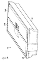
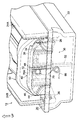
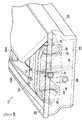
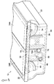
- FIGS. 1-10 An example of a container storage device according to an embodiment of the present invention will be described with reference to FIGS.
- UP shown in a figure shows the vertical direction upper direction.
- the cup holder 12 as an example of a container housing member is disposed below the center console 14 of the automobile and behind the shift lever 16.
- the cup holder 12 includes a box-shaped storage member 22 that includes an opening 20 that opens upward and extends in one direction, and a pair of opening and closing members 24 that close the opening 20. It is prepared for.
- the pair of opening / closing members 24 includes one opening / closing member 24A and the other opening / closing member 24B. In the closed position where the opening 20 is closed, the pair of opening / closing members 24 are provided so that one end portions thereof face each other. (See FIG. 3). Further, the other end side of the opening / closing member 24 is pivotally supported by the storage member 22 by a pivotal support portion 26. As a result, the pair of opening / closing members 24 is in a closed position (see FIG. 3) for closing the opening 20 and an open position (see FIG. 1) in which the opening 20 of the storage member 22 is opened and rises from the opening 20. It can be turned.
- first interlocking portions 30 that interlock the opening and closing operations of the pair of opening and closing members 24 are provided on both ends of the storage member 22 in the longitudinal direction (the direction of arrow A shown in FIG. 10, hereinafter simply referred to as the longitudinal direction).
- a fan-like plate member 32 is provided integrally with the opening / closing member 24A on the shaft support portion 26 of one opening / closing member 24A so as to be orthogonal to the rotational direction of the opening / closing member 24A.
- the plate member 32 is formed with a first rotation gear 34 that rotates along with the rotation operation when the one opening / closing member 24A is rotated along an arc centered on the shaft support portion 26. ing.
- the opening 20 of the storage member 22 moves in the opening direction (in this embodiment, the same direction as the vertical direction as an example).
- a first moving gear 36 is formed on the plate-like connecting member 40.
- a fan-like plate member 42 is provided integrally with the opening / closing member 24B on the shaft support portion 26 of the other opening / closing member 24B so as to be orthogonal to the rotational direction of the opening / closing member 24B. Further, the plate member 42 is formed with a second rotation gear 44 that rotates along with the rotation operation when the other opening / closing member 24B is rotated along an arc centered on the shaft support portion 26. ing.
- the second moving gear 46 that engages with the second rotating gear 44 and moves in the opening direction (vertical direction) when the second rotating gear 44 is rotated is connected to the connecting member similarly to the first moving gear 36. 40. That is, the first moving gear 36 and the second moving gear 46 are connected by the connecting member 40.
- the first moving gear 36 and the second moving gear 46 are formed on the inner surface (the surface facing the inner side in the longitudinal direction) of the plate-like connecting member 40.
- a concave vertical groove 48 extending in the vertical direction is formed on the outer surface of the connecting member 40, and the vertical groove 48 is provided on the inner wall surface of the storage member 22 and is movable to the convex rail portion 52. It comes to fit. That is, the connecting member 40 is configured to be movable in the vertical direction with respect to the storage member 22.
- the first rotating gear 34 and the second rotating gear 44 are in the first moving gear 36 and the second moving gear 46 in the closed position of the opening / closing member 24. Is engaged with the upper vertical direction.
- FIG. 4 As shown in FIG. 4, FIG. 5, FIG. 8B, and FIG. 8C, for example, when one of the opening / closing members 24A is rotated in the opening direction, the first rotation gear 34 is rotated. A first moving gear 36 that engages with the rotating gear 34 moves upward in the vertical direction. As a result, the second moving gear 46 connected to the first moving gear 36 by the connecting member 40 also moves upward in the vertical direction. As the second moving gear 46 moves upward in the vertical direction, the second rotating gear 44 rotates and the other opening / closing member 24B rotates in the opening direction. Then, the pair of opening / closing members 24 moves to an open position where the opening 20 of the storage member 22 is opened and rises from the opening 20, and stops by hitting a stopper (not shown).
- the first interlocking unit 30 includes a first rotation gear 34, a first movement gear 36, a second rotation gear 44, a second movement gear 46, and a connecting member 40.
- a holding member 50 for holding a container such as a cup stored in the storage member 22 is provided so as to be sandwiched between the connecting members 40 provided at both ends in the longitudinal direction.
- the holding member 50 is formed with two circular holes 50A into which the cups are inserted side by side in the longitudinal direction. Further, a pressing member 53 that presses the cup inserted into the circular hole 50A to stabilize the posture of the cup and a biasing member 51 that biases the pressing member 53 toward the cup are provided in each circular hole 50A. (See FIGS. 11A and 11B).
- a second interlocking portion 54 is provided that moves the holding member 50 to the storage position (see FIG. 9A) stored in the storage member 22 when the opening / closing member 24 is moved to the closed position. Further, the second interlocking portion 54 protrudes at least a part from the opening 20 of the storage member 22 to the outside when the opening / closing member 24 is moved to the open position (see FIG. 9C). It is supposed to be moved to.
- the second interlocking portion 54 is provided on both ends in the longitudinal direction of the holding member 50, is formed on outer wall surfaces provided on both ends in the longitudinal direction of the holding member 50, and intersects the vertical direction.
- a long groove 56 extending in a direction (a direction orthogonal in the present embodiment) is provided. Also, the long groove 56
- a convex portion 58 extending in the vertical direction is provided on the center side, and the long groove 56 is divided into a first long groove 56A and a second long groove 56B by the convex portion 58.
- the plate member 32 of the one opening / closing member 24A is provided with a first engagement pin 60 which is disposed away from the shaft support portion 26 and slidably engages with the first long groove 56A.
- the plate member 42 of the other opening / closing member 24B is provided with a second engagement pin 62 which is disposed away from the shaft support portion 26 and slidably engages with the second long groove 56B.
- a concave portion 64 is provided on the inner surface of the connecting member 40 to fit a convex portion 58 formed on the outer wall surface of the holding member 50 and extending in the vertical direction. That is, the holding member 50 is configured such that the movement direction of the holding member 50 is restricted to the vertical direction with respect to the connecting member 40. Further, as described above, the connecting member 40 is restricted in the movement direction in the vertical direction with respect to the storage member 22 by the vertical groove 48 and the rail portion 52 engaging with each other. In other words, the movement direction of the holding member 50 is restricted to the vertical direction with respect to the storage member 22.
- the holding member 50 in the closed position of the opening / closing member 24, the holding member 50 is disposed at the storage position stored inside the storage member 22, and the first engagement pin 60 is The first long groove 56A is engaged, and the second engagement pin 62 is engaged with the second long groove 56B.
- the first engagement pin 60 and the second engagement pin 62 are similarly moved in the vertical direction while being rotated. Then, the first engagement pin 60 and the second engagement pin 62 move the first long groove 56A and the second long groove 56B vertically upward while sliding in the first long groove 56A and the second long groove 56B.
- the holding member 50 protrudes at least partially from the opening 20 of the storage member 22 to the outside (FIG. 4, FIG. (See FIG. 9C).
- the second interlocking portion 54 includes the first engagement pin 60, the second engagement pin 62, the first long groove 56A, and the second long groove 56A.
- the outer shape of the connecting member 40 described above is determined so as to prevent the first interlocking portion 30 and the second interlocking portion 54 from being visually recognized from the outside. That is, when moving the opening / closing member 24 between the open position and the closed position, the movement range in which the first interlocking portion 30 and the second interlocking portion 54 move and the movement range of the connecting member 40 are taken into consideration.
- the outer shape of the member 40 is determined.
- a torsion coil spring 66 (hereinafter simply referred to as a spring) as an example of an urging member in which one end 66A is attached to the side wall of the storage member 22 and the other end 66B is fixed to the connecting member 40. Is provided on one end side of the holding member 50 in the longitudinal direction. That is, the other end 66 ⁇ / b> B of the spring 66 is attached to the opening / closing member 24 via the first interlocking portion 30 including the connecting member 40 as a component.
- the other end 66B of the spring 66 is arranged vertically downward with respect to the one end 66A. Accordingly, the connecting member 40 is urged downward in the vertical direction (see the arrow in FIG. 7A), and a moment in the closing direction is generated in the opening / closing member 24 via the first interlocking unit 30.
- the spring 66 rotates and the other end 66B of the spring 66 is rotated. And one end 66A are arranged at the same position in the vertical direction.
- the connecting member 40 is urged in the horizontal direction (see the arrow in FIG. 7B), so that the opening / closing member 24 does not generate a moment in the opening direction or the closing direction.
- dampers 70 are provided that rotate and brake the opening / closing speed of the opening / closing member 24, and the dampers 70 are attached to the outer wall surfaces provided at both ends in the longitudinal direction of the holding member 50.
- a concave mounting portion 76 is formed.
- an engagement gear 70A is provided on the outer peripheral surface of the damper 70, and an engaged gear 72 that engages with the engagement gear 70A extends in the vertical direction and is formed on the inner surface of the connecting member 40.
- the opening / closing member 24 closes the opening 20 of the storage member 22, and the spring 66 is connected to the opening / closing member 24 via the first interlocking portion 30.
- a moment in the closing direction is generated (see FIG. 7A). That is, the opening / closing member 24 is biased in the closing direction.
- the holding member 50 is housed inside the housing member 22.
- the user grasps one end of one opening / closing member 24 ⁇ / b> A and rotates the one opening / closing member 24 ⁇ / b> A in the opening direction against the urging force of the spring 66.
- the engaged gear 72 formed on the connecting member 40 also moves upward in the vertical direction.
- the damper 70 provided with the engaging gear 70A engaged with the to-be-engaged gear 72 rotates, and it brakes by rotating the opening-and-closing speed of the opening-and-closing member 24.
- the amount of movement of the connecting member 40 in the vertical direction is such that the first rotation gear 34 and the second rotation gear 44 are closer to the shaft support portion 26 than the first engagement pin 60 and the second engagement pin 62. Since it is arranged at a position, the holding member 50 is configured to be smaller than the amount of vertical movement of the holding member 50. That is, the connecting member 40 does not protrude above the holding member 50.
- the user grasps one end of one opening / closing member 24A and rotates it in the opening direction, for example.
- the pair of opening / closing members 24 rotate from the intermediate position toward the open position.
- the spring 66 rotates and the other end 66B of the spring 66 is disposed vertically above the one end 66A.
- the connecting member 40 is urged upward in the vertical direction, a moment in the opening direction is generated in the pair of opening / closing members 24 via the first interlocking portion 30, and the pair of opening / closing members 24 moves to the opening position.
- the first moving gear 36 and the second moving gear 46 move upward in the vertical direction when the connecting member 40 moves upward in the vertical direction.
- the first rotation gear 34 and the second rotation gear 44 that engage with the first movement gear 36 and the second movement gear 46 rotate about the shaft support portion 26.
- the pair of opening / closing members 24 moves from the intermediate position to the opening position (see FIGS. 1 and 4) that opens the opening 20 of the storage member 22 and rises from the opening 20, and hits a stopper (not shown). Stop.
- the engaged gear 72 formed in the connecting member 40 also moves upward in the vertical direction.
- the damper 70 provided with the engaging gear 70A engaged with the to-be-engaged gear 72 rotates, and the opening-and-closing speed of the opening-and-closing member 24 is braked.
- the opening-and-closing member 24 moves from an opening position to a closing position by performing the reverse process of the process mentioned above.
- the opening / closing member 24 rises from the opening 20 at the open position of the opening / closing member 24, the opening / closing member 24 that opens and closes the opening 20 of the storage member 22 is stored in the storage member 22. It is possible to prevent a container such as a cup from falling.
- the outer shape of the connecting member 40 is determined so as to prevent the first interlocking portion 30 and the second interlocking portion 54 from being visually recognized from the outside, the appearance quality can be improved.
- the second interlocking unit 54 causes the holding member 50 to protrude from the opening 20 of the storage member 22.
- the holding member 50 can suppress effectively that containers, such as a cup accommodated in the storage member 22, fall down. That is, the upper part of the container can be supported at a higher position.
- first engagement pin 60 and the second engagement pin 62, and the first long groove 56A and the second long groove 56B in which the first engagement pin 60 and the second engagement pin 62 are slidably engaged are provided.
- the holding member 50 can be moved to the storage position or the protruding position with a simple configuration.
- the opening / closing member 24 can be easily moved to the opening / closing position or the closing position.
- the damper 70 brakes the opening / closing speed of the opening / closing member 24 that is opened or closed by the urging force of the spring 66, the texture of the opening / closing operation of the opening / closing member 24 can be improved.
- the amount of movement of the connecting member 40 in the vertical direction is smaller than the amount of movement of the holding member 50 in the vertical direction. Therefore, even if the holding member 50 moves to the protruding position, the connecting member 40 can be prevented from protruding from the holding member 50.
- the present invention has been described in detail with respect to specific embodiments, the present invention is not limited to such embodiments, and various other embodiments are possible within the scope of the present invention. It is clear to the contractor.
- the spring 66 is provided on one end side in the longitudinal direction of the holding member 50, but may be provided on both sides in the longitudinal direction.
- the opening direction of an opening part is a vertical direction. May be different.
- Cup holder (container storage device) 20 Opening portion 22 Storage member 24 Opening / closing member 26 Shaft support portion 30 First interlocking portion 34 First rotating gear 36 First moving gear 40 Connecting member 44 Second rotating gear 46 Second moving gear 50 Holding member 54 Second interlocking portion 56 long groove 56A first long groove 56B second long groove 60 first engagement pin 62 second engagement pin 66 spring (biasing member) 70 damper
Landscapes
- Engineering & Computer Science (AREA)
- Mechanical Engineering (AREA)
- Physics & Mathematics (AREA)
- Thermal Sciences (AREA)
- Transportation (AREA)
- Passenger Equipment (AREA)
- Vehicle Step Arrangements And Article Storage (AREA)
Abstract
収納部材の開口部を開閉する開閉部材を用いて、収納部材に収納された容器が倒れるのを抑制することができる容器収納装置を得る。 一方の開閉部材(24A)を開放させると、第1連動部によって他方の開放部材(24B)も開放される。一対の開放部材(24)は、開放位置で、開口部(20)から立ち上がって停止する。このため、収納部材(22)の開口部(20)を開閉する開閉部材(24)を用いて、収納部材(22)に収納されたカップ等の容器が倒れるのを抑制することができる。
Description
本発明は、カップ等の容器を収納する容器収納装置に関する。
特許文献(特開2008-221993号公報)に記載の容器ホルダ装置(容器収納装置)には、不使用時に、容器を保持する収納部材の開口部を覆う蓋体(開閉部材)が設けられている。そして、この収納部材に容器を保持させる際には、この蓋体は容器の底面に押されて下方へ移動するようになっている。
しかしながら、従来の容器収納装置では、収納部材に容器を保持される際には、収納部材の開口部を開閉する開閉部材が下方へ移動する構成となっている。このため、収納部材に保持された容器が倒れるのをこの開閉部材で抑制することができなかった。
本発明の課題は、収納部材の開口部を開閉する開閉部材を用いて、収納部材に収納された容器が倒れるのを抑制することである。
本発明の第一態様の容器収納装置では、開口部を備える箱状の収納部材と、一端部が対向するように前記収納部材の開口部に設けられ、他端側が前記収納部材に軸支されると共に、前記収納部材の前記開口部を開放して前記開口部から立ち上がる開放位置と前記収納部材の前記開口部を閉止する閉止位置とに回動可能とされる一対の開閉部材と、一対の前記開閉部材の開閉動作を連動させる第1連動部と、前記収納部材の内部に設けられ、前記収納部材に収納される容器を保持する保持部材と、を備える。
上記構成によれば、収納部材の開口部を開閉する一対の開閉部材は、一端部が対向するように収納部材の開口部に設けられ、他端側が収納部材に軸支されている。そして、一対の開閉部材は、収納部材の開口部を開放して開口部から立ち上がる開放位置と、収納部材の開口部を閉止する閉止位置とに移動可能とされる。また、第1連動部が一対の開閉部材の開閉動作を連動させる。
さらに、収納部材の内部に設けられる保持部材が、一対の開閉部材が開放位置へ移動して開口部が開放され収納部材に収納される容器を保持する。
ここで、収納部材に容器が収納された状態では、一対の開閉部材は、開口部から立ち上がる開放位置に移動している。このように、開閉部材が、開口部から立ち上がっているため、収納部材の開口部を開閉する開閉部材を用いて、収納部材に収納された容器が倒れるのを抑制することができる。
上記態様において、前記第1連動部は、一方の前記開閉部材に設けられ、一方の前記開閉部材を回動させるとこの回動動作に伴って回動する第1回動ギアと、前記第1回動ギアと係合し、前記第1回動ギアを回動させると前記収納部材の前記開口部の開口方向に移動する第1移動ギアと、他方の前記開閉部材に設けられ、他方の前記開閉部材を回動させるとこの回動動作に伴って回動する第2回動ギアと、前記第2回動ギアと係合し、前記第2回動ギアが回動させると前記収納部材の前記開口部の開口方向に移動する第2移動ギアと、前記第1移動ギアと前記2移動ギアとを連結させる連結部材と、を備え、前記連結部材の外形形状は、前記第1回動ギア、前記第1移動ギア、前記第2回動ギア、前記第2移動ギアが外部から視認されるのを防止するように決められる。
上記構成によれば、閉止位置に配置される一方の開閉部材を回動させると第1回動ギアが回動する。また、第1回動ギアを回動させることで第1移動ギアが収納部材の開口部の開口方向に移動する。第1移動ギアが開口方向に移動すると、連結部材によって第1移動ギアと連結されている第2移動ギアが開口方向に移動する。第2移動ギアが開口方向に移動することで、第2回動ギアが回動して他方の開閉部材が回動する。このように、一対の開閉部材の開閉動作が連動する。
ここで、連結部材は、第1回動ギア、第1移動ギア、第2回動ギア、第2移動ギアが外部から視認されるのを防止するように決められている。このため、第1回動ギア、第1移動ギア、第2回動ギア、第2移動ギアは外部から視認することができず、外観品質を向上させることができる。
上記態様において、前記開閉部材が閉止位置に移動したときは、前記保持部材を前記収納部材の内部に収納される収納位置に移動させ、前記開閉部材が開放位置に移動したときは、前記保持部材を前記収納部材の前記開口部から外部に少なくとも一部を突出させる突出位置に移動させる第2連動部が設けられる。
上記構成によれば、開閉部材を閉止位置に移動させたときは、第2連動部が保持部材を収納部材の内部に収納される収納位置に移動させる。一方、開閉部材を開放位置に移動させたときは、第2連動部が保持部材を収納部材の開口部から外部に少なくとも一部を突出させる突出位置に移動させる。
このように、第2連動部が、保持部材を収納部材の開口部から突出させることで、収納部材に収納された容器が倒れるのを効果的に抑制することができる。
上記態様において、前記第2連動部は、前記保持部材に形成され、前記収納部材の前記開口部の開口方向に対して交差する方向に延びる長溝と、前記開閉部材に設けられると共に、前記開閉部材の軸支部から離れて配置され、前記長溝にスライド可能に係合する係合ピンと、を備える。
上記構成によれば、開閉部材を閉止位置から開放位置へ回動させると、開閉部材に設けられた係合ピンも回動する。開閉部材の回動に伴って回動する係合ピンは、保持部材に形成された長溝をスライドしながら保持部材を収納位置から突出位置へ移動させる。
これに対し、開閉部材を開放位置から閉止位置へ回動させると、開閉部材に設けられた係合ピンも回動する。開閉部材の回動に伴って回動する係合ピンは、保持部材に形成された長溝をスライドしながら保持部材を突出位置から収納位置へ移動させる。
このように簡易な構成で、保持部材を収納位置又は突出位置に移動させることができる。
上記態様において、前記連結部材の外形形状は、前記第2連動部が外部から視認されるのを防止するように決められる。
上記構成によれば、連結部材は、第2連動部が外部から視認されるのを防止するように設けられているため、さらに、外観品質を向上させることができる。
上記態様において、一端が前記収納部材に取り付けられ、他端が一対の前記開閉部材に直接又は間接的に取り付けられ、一対の前記開閉部材の所定の開閉位置から前記開閉部材を開放方向に移動させると前記開閉部材に開放方向のモーメントを発生させ、又は一対の前記開閉部材の所定の開閉位置から前記開閉部材を閉止方向に移動させると前記開閉部材に閉止方向のモーメントを発生させる付勢部材を備える。
上記構成によれば、一方が収納部材に取り付けられ、他方が一対の開閉部材に直接又は間接的に取り付けられた付勢部材は、開閉部材の所定の開閉位置から開閉部材を開放方向に移動させると開閉部材に開放方向のモーメントを発生させる。一方、この付勢部材は、開閉部材の所定の開閉位置から開閉部材を閉止方向に移動させると開閉部材に閉止方向のモーメントを発生させる。
このように、付勢部材が、開閉部材に開放方向又は閉止方向のモーメントを発生させることで、容易に開閉部材を開放位置又は閉止位置に移動させることができる。
上記態様において、前記開閉部材の開閉速度を制動するダンパが設けられる。
上記構成によれば、ダンパが、付勢部材によって開放又は閉止される開閉部材の開閉速度を制動する。これにより、開閉部材の開放又は閉止動作の質感を向上させることができる。
本発明によれば、収納部材の開口部を開閉する開閉部材を用いて、収納部材に収納された容器が倒れるのを抑制することができる。
本発明の実施形態に係る容器収納装置の一例について図1~図12に従って説明する。なお、図中に示すUPは、鉛直方向上方を示す。
(全体構成)
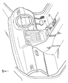
図12に示されるように、容器収納部材の一例としてのカップホルダー12は、自動車のセンターコンソール14の下方であってシフトレバー16の後方に配置されている。
(要部構成)
図10に示されるように、カップホルダー12は、上方が開放された開口部20を備えると共に一方向に延びる箱状の収納部材22と、この開口部20を閉止する一対の開閉部材24とを備えて構成されている。
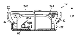
一対の開閉部材24は、一方の開閉部材24Aと、他方の開閉部材24Bとから構成され、開口部20を閉止する閉止位置では、一対の開閉部材24は、一端部が対向するように設けられている(図3参照)。さらに、開閉部材24の他端側は収納部材22に軸支部26で軸支されている。これにより、一対の開閉部材24は、開口部20を閉止する閉止位置(図3参照)と、収納部材22の開口部20を開放して開口部20から立ち上がる開放位置(図1参照)とに回動可能とされている。
また、一対の開閉部材24の開閉動作を連動させる第1連動部30が、収納部材22の長手方向(図10に示す矢印A方向、以下単に長手方向と言う)両端側に設けられている。
詳細には、一方の開閉部材24Aの軸支部26には、開閉部材24Aの回動方向に対して直交するように扇状の板部材32が、開閉部材24Aと一体的に設けられている。また、この板部材32には、一方の開閉部材24Aを回動させるとこの回動動作に伴って回動する第1回動ギア34が、軸支部26を中心とする円弧に沿って形成されている。
さらに、第1回動ギア34と係合し、第1回動ギア34を回動させると収納部材22の開口部20の開口方向(本実施形態では、一例として鉛直方向と同一方向)に移動する第1移動ギア36が、板状の連結部材40に形成されている。
同様に、他方の開閉部材24Bの軸支部26には、開閉部材24Bの回動方向に対して直交するように扇状の板部材42が、開閉部材24Bと一体的に設けられている。また、この板部材42には、他方の開閉部材24Bを回動させるとこの回動動作に伴って回動する第2回動ギア44が、軸支部26を中心とする円弧に沿って形成されている。
さらに、第2回動ギア44と係合し、第2回動ギア44を回動させると開口方向(鉛直方向)に移動する第2移動ギア46が、第1移動ギア36と同様に連結部材40に形成されている。つまり、連結部材40によって第1移動ギア36と第2移動ギア46とが連結されている。
また、第1移動ギア36及び第2移動ギア46は、板状の連結部材40の内面(長手方向内側に向いた面)に形成されている。
さらに、連結部材40の外面には、鉛直方向に延びる凹状の縦溝48が形成されており、この縦溝48は、収納部材22の内壁面に設けられ凸状のレール部52へ移動可能に嵌るようになっている。つまり、連結部材40は、収納部材22に対して鉛直方向に移動可能とされる構成となっている。
以上の構成により、図6、図8Aに示されるように、開閉部材24の閉止位置では、第1回動ギア34及び第2回動ギア44は、第1移動ギア36及び第2移動ギア46の鉛直方向上方と係合している。
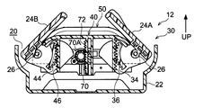
図4、図5、図8B、図8Cに示されるように、例えば、一方の開閉部材24Aを開放方向に回動させると、第1回動ギア34が回動し、これに伴って第1回動ギア34と係合する第1移動ギア36が鉛直方向上方へ移動するようになっている。これにより、連結部材40によって第1移動ギア36と連結される第2移動ギア46も鉛直方向上方へ移動する。そして、第2移動ギア46の鉛直方向上方への移動により、第2回動ギア44が回動し、他方の開閉部材24Bが開放方向に回動するようになっている。そして、一対の開閉部材24は、収納部材22の開口部20を開放して開口部20から立ち上がる開放位置へ移動し、図示せぬストッパーと当って停止するようになっている。
このように、第1連動部30を設けることで、一対の開閉部材24の開閉動作が連動するようになっている。そして、第1連動部30は、第1回動ギア34、第1移動ギア36、第2回動ギア44、第2移動ギア46、及び連結部材40を含んで構成されている。
一方、図10に示されるように、長手方向両端側に設けられた連結部材40に挟まれるように、収納部材22に収納されるカップ等の容器を保持する保持部材50が設けられている。
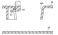
そして、この保持部材50には、カップが挿入される円孔50Aが長手方向に並んで2個形成されている。また、円孔50Aに挿入されたカップを押圧してカップの姿勢を安定させる押圧部材53と、この押圧部材53をカップに向って付勢する付勢部材51とが夫々の円孔50Aに設けられている(図11A、図11B参照)。
また、開閉部材24を閉止位置に移動させたときは、保持部材50を収納部材22の内部に収納される収納位置(図9A参照)に移動させる第2連動部54が、設けられている。また、この第2連動部54は、開閉部材24を開放位置に移動させたときは、保持部材50を収納部材22の開口部20から外部に少なくとも一部を突出させる突出位置(図9C参照)に移動させるようになっている。
詳細には、第2連動部54は、保持部材50の長手方向両端側に設けられており、保持部材50の長手方向両端部に設けられた外壁面に形成され、鉛直方向に対して交差する方向(本実施形態では直交する方向)に延びる長溝56を備えている。また、長溝56の
中央側には、鉛直方向に延びる凸部58が設けられており、長溝56は、凸部58により第1長溝56Aと第2長溝56Bとに分割されている。
さらに、一方の開閉部材24Aの板部材32には、軸支部26から離れて配置されると共に、第1長溝56Aにスライド可能に係合する第1係合ピン60が設けられている。同様に、他方の開閉部材24Bの板部材42には、軸支部26から離れて配置されると共に、第2長溝56Bにスライド可能に係合する第2係合ピン62が設けられている。
また、連結部材40の内面には、保持部材50の外壁面に形成された鉛直方向に延びる凸部58が嵌る凹部64が設けられている。つまり、保持部材50は、連結部材40に対して移動方向が鉛直方向に規制されるようになっている。また、前述したように、連結部材40は、縦溝48とレール部52とが係合することで、収納部材22に対して移動方向が鉛直方向に規制されている。すなわち、保持部材50は、収納部材22に対して移動方向が鉛直方向に規制されるようになっている。
以上の構成により、図6、図9Aに示されるように、開閉部材24の閉止位置では、保持部材50は収納部材22の内部に収納される収納位置に配置され、第1係合ピン60は第1長溝56Aに係合し、第2係合ピン62は第2長溝56Bに係合している。
図4、図5、図9B、図9Cに示されるように、例えば、一方の開閉部材24Aを開放方向に回動させると、第1連動部30により、他方の開閉部材24Bも連動して開放方向に回動する。
一対の開閉部材24が連動して開放方向に回動すると、第1係合ピン60及び第2係合ピン62が同様に回動しながら鉛直方向上方へ移動する。そうすると、第1係合ピン60及び第2係合ピン62が、第1長溝56A及び第2長溝56B内をスライドしながら第1長溝56A及び第2長溝56Bを鉛直方向上方へ移動させる。
このように、第1長溝56A及び第2長溝56Bを鉛直方向上方へ移動させることで、保持部材50が、収納部材22の開口部20から外部に少なくとも一部が突出する突出位置(図4、図9C参照)に移動するようになっている。
以上説明したように、第2連動部54は、第1係合ピン60、第2係合ピン62、第1長溝56A 及び第2長溝56Aを含んで構成されている。
また、前述した連結部材40の外形形状は、第1連動部30及び第2連動部54が外部から視認されるのを防止するように決められている。つまり、開閉部材24を開放位置と閉止位置との間を移動させる際に、第1連動部30及び第2連動部54が移動する移動範囲、並びに連結部材40の移動範囲を考慮して、連結部材40の外形形状が決められている。
一方、図10に示されるように、一端66Aが収納部材22の側壁に取り付けられ、他端66Bが連結部材40に固定される付勢部材の一例としての捩じりコイルスプリング66(以下単にスプリングと言う)が、保持部材50の長手方向一端側に設けられている。つまり、スプリング66の他端66Bは、連結部材40を構成部品として含む第1連動部30を介して開閉部材24に取り付けられている。
図6、図7Aに示されるように、開閉部材24の閉止位置では、スプリング66の他端66Bが、一端66Aに対して鉛直方向下方に配置されている。これにより、連結部材40が鉛直方向下方に付勢(図7A矢印参照)され、第1連動部30を介して開閉部材24に閉止方向のモーメントが発生するようになっている。
図5、図7Bに示されるように、開閉部材24の閉止位置と開放位置との中間である所定の開閉位置(以下中間位置と言う)では、スプリング66が回転してスプリング66の他端66Bと一端66Aとが鉛直方向において同位置に配置される。これにより、連結部材40が水平方向に付勢(図7B矢印参照)されるため、開閉部材24に開放方向又は閉止方向のモーメントが発生しないようになっている。
図4、図7B、図7Cに示されるように、一対の開閉部材24を中間位置から開放位置に向けて回動させると、スプリング66が回転してスプリング66の他端66Bが、一端66Aに対して鉛直方向上方に配置されている。これにより、連結部材40が鉛直方向上方に付勢(図7C矢印参照)され、第1連動部30を介して開閉部材24に開放方向のモーメントが発生するようになっている。
以上より、開閉部材24の中間位置より開閉部材24を開放方向に移動させると、スプリング66の付勢力によって開閉部材24に開放方向のモーメントが発生する。一方、開閉部材24の中間位置より開閉部材24を閉止方向に移動させると、スプリング66の付勢力によって開閉部材24に閉止方向のモーメントが発生するようになっている。
一方、図10に示されるように、開閉部材24の開閉速度を回転して制動するダンパ70が設けられ、保持部材50の長手方向両端部に設けられた外壁面には、このダンパ70が取り付けられる凹状の取付部76が形成されている。
また、ダンパ70の外周面には係合ギア70Aが設けられ、この係合ギア70Aと係合する被係合ギア72が、鉛直方向に延びて連結部材40の内面に形成されている。
(作用・効果)
先ず、閉止位置に配置された一対の開閉部材24を開放させる動作について説明する。
図3、図6に示されるように、開閉部材24の閉止位置では、開閉部材24が収納部材22の開口部20を閉止しており、スプリング66は第1連動部30を介して開閉部材24に閉止方向のモーメントを発生させている(図7A参照)。つまり、開閉部材24は閉止方向に付勢されている。また、保持部材50は、収納部材22の内部に収納されている。
カップホルダー12を使用する際には、先ずユーザは、例えば一方の開閉部材24Aの一端部を把持して、一方の開閉部材24Aをスプリング66の付勢力に対抗して開方向へ回動させる。
一方の開閉部材24Aを回動させると、図8A、図8B、図8Cに示されるように、第1回動ギア34が軸支部26を中心に回動し、これに伴って第1回動ギア34と係合する第1移動ギア36が鉛直方向上方へ移動する。これにより、連結部材40によって第1移動ギア36と連結される第2移動ギア46も鉛直方向上方へ移動する。つまり、連結部材40が鉛直方向上方へ移動する。
そして、第2移動ギア46の鉛直方向上方への移動により、第2移動ギア46と係合する第2回動ギア44が回動し、他方の開閉部材24Bが開放方向に回動し、一対の開閉部材24が連動して中間位置(図2、図5参照)へ移動する。
また、連結部材40が鉛直方向上方に移動することで、連結部材40に形成された被係合ギア72も鉛直方向上方に移動する。そして、被係合ギア72と係合している係合ギア70Aを備えるダンパ70が回転し、開閉部材24の開閉速度を回転して制動する。
一方、図9A、図9Bに示されるように、一対の開閉部材24が閉止位置から中間位置に回動すると、第1係合ピン60及び第2係合ピン62が同様に回動しながら鉛直方向上方へ移動する。そうすると、第1係合ピン60及び第2係合ピン62が、第1長溝56A及び第2長溝56B内をスライドしながら第1長溝56A及び第2長溝56Bを鉛直方向上方へ移動させる。そして、第1長溝56A及び第2長溝56Bを鉛直方向上方へ移動させることで、保持部材50が鉛直方向上方へ移動する。
なお、連結部材40の鉛直方向上方への移動量は、第1回動ギア34、第2回動ギア44が第1係合ピン60、第2係合ピン62に対して軸支部26に近い位置に配置されているため、保持部材50の鉛直方向上方への移動量より小さくなるようになっている。つまり、連結部材40が保持部材50より上方に突出しないようになっている。
また、図7Bに示されるように、一対の開閉部材24が中間位置に到達すると、スプリング66が回転してスプリング66の他端66Bと一端66Aとが鉛直方向において同位置に配置される。これにより、連結部材40が水平方向に付勢されるため、開閉部材24に開放方向又は閉止方向のモーメントが発生しない(デットポイント)。
さらに、中間位置に配置された一対の開閉部材24を開放位置に向けて移動させる際には、ユーザは、例えば一方の開閉部材24Aの一端部を把持して、開放方向へ回動させる。
図7B、図7Cに示されるように、一対の開閉部材24が中間位置から開放位置に向けて回動する。これにより、スプリング66が回転してスプリング66の他端66Bが、一端66Aに対して鉛直方向上方に配置されている。これにより、連結部材40が鉛直方向上方に付勢され、第1連動部30を介して一対の開閉部材24に開放方向のモーメントが発生し、一対の開閉部材24は開放位置へ移動する。
詳細には、図8B、図8Cに示されるように、連結部材40が鉛直方向上方へ移動することで、第1移動ギア36及び第2移動ギア46が鉛直方向上方へ移動する。これにより、第1移動ギア36及び第2移動ギア46と係合する第1回動ギア34及び第2回動ギア44が軸支部26を中心に回動する。そして、一対の開閉部材24は、中間位置から収納部材22の開口部20を開放して開口部20から立ち上がる開放位置(図1、図4参照)へと移動し、図示せぬストッパーと当って停止する。
また、連結部材40が鉛直方向上方へ移動することで、連結部材40に形成された被係合ギア72も鉛直方向上方に移動する。そして、被係合ギア72と係合している係合ギア70Aを備えるダンパ70が回転し、開閉部材24の開閉速度を制動する。
一方、図9B、図9Cに示されるように、一対の開閉部材24が中間位置から開放位置に回動すると、第1係合ピン60及び第2係合ピン62が同様に回動しながら鉛直方向上方へ移動する。そうすると、第1係合ピン60及び第2係合ピン62が、第1長溝56A及び第2長溝56B内をスライドしながら第1長溝56A及び第2長溝56Bを鉛直方向上方へ移動させる。そして、第1長溝56A及び第2長溝56Bを鉛直方向上方へ移動させることで、保持部材50が鉛直方向上方へ移動し、保持部材50は突出位置へ移動する。これにより、カップがカップホルダー12に収納可能となる。
なお、一対の開閉部材24を開放位置から閉止位置へ移動させる場合には、前述した工程の逆工程を行うことで、開閉部材24は開放位置から閉止位置へ移動する。
以上説明したように、開閉部材24の開放位置では、開閉部材24が、開口部20から立ち上がっているため、収納部材22の開口部20を開閉する開閉部材24を用いて、収納部材22に収納されたカップ等の容器が倒れるのを抑制することができる。
また、連結部材40の外形形状は、第1連動部30及び第2連動部54が外部から視認されるのを防止するように決められているため、外観品質を向上させることができる。
また、開閉部材24を開放位置へ移動させると、第2連動部54が、保持部材50を収納部材22の開口部20から突出させる。これにより、収納部材22に収納されたカップ等の容器が倒れるのを効果的に抑制することができる。つまり、より高い位置で容器の上方を支持することができる。
また、第1係合ピン60及び第2係合ピン62と、第1係合ピン60及び第2係合ピン62がスライド可能に係合する第1長溝56A及び第2長溝56Bとを設けることで、簡易な構成で、保持部材50を収納位置又は突出位置に移動させることができる。
また、スプリング66が、開閉部材24に開放方向又は閉止方向のモーメントを発生させることで、容易に開閉部材24を開閉位置又は閉止位置に移動させることができる。
また、ダンパ70が、スプリング66の付勢力によって開放又は閉止される開閉部材24の開閉速度を制動するため、開閉部材24の開放又は閉止動作の質感を向上させることができる。
また、連結部材40の鉛直方向上方への移動量は、保持部材50の鉛直方向上方への移動量より小さくなるようになっている。これにより、保持部材50が突出位置へ移動しても、連結部材40が保持部材50から突出するのを防止することができる。
なお、本発明を特定の実施形態について詳細に説明したが、本発明は係る実施形態に限定されるものではなく、本発明の範囲内にて他の種々の実施形態が可能であることは当業者にとって明らかである。例えば、上記実施形態では、スプリング66を保持部材50の長手方向一端側に設けたが、長手方向両側に設けてもよい。
また、上記実施形態では、収納部材22の開口部20の開口方向が、鉛直方向となる場合を例にとって説明したが、特にこれに限定されることなく、開口部の開口方向が、鉛直方向と異なっていてもよい。
また、上記実施形態では、スプリング66の他端66Bを第1連動部30及び保持部材50を介して開閉部材24に取り付けたが、特にこれに限定されることなく、スプリングの他端を直接開閉部材に取り付けてもよい。
(符号の説明)
(符号の説明)
12 カップホルダー(容器収納装置)
20 開口部
22 収納部材
24 開閉部材
26 軸支部
30 第1連動部
34 第1回動ギア
36 第1移動ギア
40 連結部材
44 第2回動ギア
46 第2移動ギア
50 保持部材
54 第2連動部
56 長溝
56A 第1長溝
56B 第2長溝
60 第1係合ピン
62 第2係合ピン
66 スプリング(付勢部材)
70 ダンパ
20 開口部
22 収納部材
24 開閉部材
26 軸支部
30 第1連動部
34 第1回動ギア
36 第1移動ギア
40 連結部材
44 第2回動ギア
46 第2移動ギア
50 保持部材
54 第2連動部
56 長溝
56A 第1長溝
56B 第2長溝
60 第1係合ピン
62 第2係合ピン
66 スプリング(付勢部材)
70 ダンパ
Claims (7)
- 開口部を備える箱状の収納部材と、
一端部が対向するように前記収納部材の開口部に設けられ、他端側が前記収納部材に軸支されると共に、前記収納部材の前記開口部を開放して前記開口部から立ち上がる開放位置と前記収納部材の前記開口部を閉止する閉止位置とに回動可能とされる一対の開閉部材と、
一対の前記開閉部材の開閉動作を連動させる第1連動部と、
前記収納部材の内部に設けられ、前記収納部材に収納される容器を保持する保持部材と、
を備える容器収納装置。 - 前記第1連動部は、
一方の前記開閉部材に設けられ、一方の前記開閉部材を回動させるとこの回動動作に伴って回動する第1回動ギアと、
前記第1回動ギアと係合し、前記第1回動ギアを回動させると前記収納部材の前記開口部の開口方向に移動する第1移動ギアと、
他方の前記開閉部材に設けられ、他方の前記開閉部材を回動させるとこの回動動作に伴って回動する第2回動ギアと、
前記第2回動ギアと係合し、前記第2回動ギアが回動させると前記収納部材の前記開口部の開口方向に移動する第2移動ギアと、
前記第1移動ギアと前記2移動ギアとを連結させる連結部材と、を備え、
前記連結部材の外形形状は、前記第1回動ギア、前記第1移動ギア、前記第2回動ギア、前記第2移動ギアが外部から視認されるのを防止するように決められる請求項1項に記載の容器収納装置。 - 前記開閉部材が閉止位置に移動したときは、前記保持部材を前記収納部材の内部に収納される収納位置に移動させ、前記開閉部材が開放位置に移動したときは、前記保持部材を前記収納部材の前記開口部から外部に少なくとも一部を突出させる突出位置に移動させる第2連動部が設けられた請求項1又は2に記載の容器収納装置。
- 前記第2連動部は、
前記保持部材に形成され、前記収納部材の前記開口部の開口方向に対して交差する方向に延びる長溝と、
前記開閉部材に設けられると共に、前記開閉部材の軸支部から離れて配置され、前記長溝にスライド可能に係合する係合ピンと、
を備える請求項3に記載の容器収納装置。 - 前記連結部材の外形形状は、前記第2連動部が外部から視認されるのを防止するように決められる請求項3又は4に記載の容器収納装置。
- 一端が前記収納部材に取り付けられ、他端が一対の前記開閉部材に直接又は間接的に取り付けられ、一対の前記開閉部材の所定の開閉位置から前記開閉部材を開放方向に移動させると前記開閉部材に開放方向のモーメントを発生させ、又は一対の前記開閉部材の所定の開閉位置から前記開閉部材を閉止方向に移動させると前記開閉部材に閉止方向のモーメントを発生させる付勢部材を備える請求項1~5の何れか1項に記載の容器収納装置。
- 前記開閉部材の開閉速度を制動するダンパが設けられる請求項6に記載の容器収納装置。
Applications Claiming Priority (2)
| Application Number | Priority Date | Filing Date | Title |
|---|---|---|---|
| JP2010-204378 | 2010-09-13 | ||
| JP2010204378A JP2012056533A (ja) | 2010-09-13 | 2010-09-13 | 容器収納装置 |
Publications (1)
| Publication Number | Publication Date |
|---|---|
| WO2012035973A1 true WO2012035973A1 (ja) | 2012-03-22 |
Family
ID=45831443
Family Applications (1)
| Application Number | Title | Priority Date | Filing Date |
|---|---|---|---|
| PCT/JP2011/069652 Ceased WO2012035973A1 (ja) | 2010-09-13 | 2011-08-30 | 容器収納装置 |
Country Status (2)
| Country | Link |
|---|---|
| JP (1) | JP2012056533A (ja) |
| WO (1) | WO2012035973A1 (ja) |
Cited By (1)
| Publication number | Priority date | Publication date | Assignee | Title |
|---|---|---|---|---|
| CN105109390A (zh) * | 2015-08-27 | 2015-12-02 | 宁波南方汽车零部件有限公司 | 汽车杯架装置 |
Families Citing this family (2)
| Publication number | Priority date | Publication date | Assignee | Title |
|---|---|---|---|---|
| US8573552B2 (en) * | 2010-09-29 | 2013-11-05 | Lear Corporation | Cup holder assembly having a pair of lids and a single release button |
| KR102867172B1 (ko) * | 2023-04-05 | 2025-10-01 | 현대트랜시스 주식회사 | 반자동 컵홀더 |
Citations (6)
| Publication number | Priority date | Publication date | Assignee | Title |
|---|---|---|---|---|
| JPH0534035U (ja) * | 1991-08-14 | 1993-05-07 | 日産自動車株式会社 | カツプホルダ構造 |
| JPH0717578Y2 (ja) * | 1988-12-28 | 1995-04-26 | 三菱自動車工業株式会社 | 車両におけるカップホルダー |
| JPH10297338A (ja) * | 1997-04-24 | 1998-11-10 | Toyota Auto Body Co Ltd | カップホルダー付きアームレスト |
| JPH11278514A (ja) * | 1998-03-31 | 1999-10-12 | Nifco Inc | 蓋部材の開閉構造 |
| JP2008221992A (ja) * | 2007-03-12 | 2008-09-25 | Toyoda Gosei Co Ltd | 容器ホルダ装置 |
| JP2009040196A (ja) * | 2007-08-08 | 2009-02-26 | Toyoda Gosei Co Ltd | カップホルダ |
Family Cites Families (1)
| Publication number | Priority date | Publication date | Assignee | Title |
|---|---|---|---|---|
| DE102007048947A1 (de) * | 2007-10-12 | 2009-04-16 | Fischer Automotive Systems Gmbh & Co. Kg | Halter für einen Getränkebehälter |
-
2010
- 2010-09-13 JP JP2010204378A patent/JP2012056533A/ja active Pending
-
2011
- 2011-08-30 WO PCT/JP2011/069652 patent/WO2012035973A1/ja not_active Ceased
Patent Citations (6)
| Publication number | Priority date | Publication date | Assignee | Title |
|---|---|---|---|---|
| JPH0717578Y2 (ja) * | 1988-12-28 | 1995-04-26 | 三菱自動車工業株式会社 | 車両におけるカップホルダー |
| JPH0534035U (ja) * | 1991-08-14 | 1993-05-07 | 日産自動車株式会社 | カツプホルダ構造 |
| JPH10297338A (ja) * | 1997-04-24 | 1998-11-10 | Toyota Auto Body Co Ltd | カップホルダー付きアームレスト |
| JPH11278514A (ja) * | 1998-03-31 | 1999-10-12 | Nifco Inc | 蓋部材の開閉構造 |
| JP2008221992A (ja) * | 2007-03-12 | 2008-09-25 | Toyoda Gosei Co Ltd | 容器ホルダ装置 |
| JP2009040196A (ja) * | 2007-08-08 | 2009-02-26 | Toyoda Gosei Co Ltd | カップホルダ |
Cited By (1)
| Publication number | Priority date | Publication date | Assignee | Title |
|---|---|---|---|---|
| CN105109390A (zh) * | 2015-08-27 | 2015-12-02 | 宁波南方汽车零部件有限公司 | 汽车杯架装置 |
Also Published As
| Publication number | Publication date |
|---|---|
| JP2012056533A (ja) | 2012-03-22 |
Similar Documents
| Publication | Publication Date | Title |
|---|---|---|
| US7591395B2 (en) | Acceleration/deceleration mechanism and vehicle small article compartment having acceleration/deceleration mechanism | |
| JP5364420B2 (ja) | カップホルダ | |
| JP5965166B2 (ja) | 収納装置 | |
| US20100154309A1 (en) | Door opening and closing structure and door opening and closing system | |
| JP5890185B2 (ja) | 車両用コンソールボックス | |
| US20110259906A1 (en) | Cup holder | |
| WO2012035973A1 (ja) | 容器収納装置 | |
| JP4307327B2 (ja) | 車両用物品収納装置 | |
| JP5357590B2 (ja) | 回動体装置及び収納装置 | |
| JP5459167B2 (ja) | 車両用収納装置 | |
| JP6573662B2 (ja) | 家具又は家庭用器具用のヒンジ | |
| JP2012135668A (ja) | 金属ブレーキ機構及び家庭用電気製品 | |
| JP2018071076A (ja) | 回動体装置及び収納装置 | |
| JP5067626B2 (ja) | 車両用収納装置 | |
| KR20130139507A (ko) | 슬라이딩도어용 오픈유지장치 | |
| JP2007261564A (ja) | 車室内収納ケース | |
| JP5453133B2 (ja) | 開閉部材の開閉機構、容器 | |
| JP5020851B2 (ja) | 車両用収納装置のドアの開閉装置 | |
| JP2010215071A (ja) | リッド開閉装置 | |
| JP5702559B2 (ja) | 開閉装置 | |
| JP5813490B2 (ja) | 車両用収納装置 | |
| JP5544641B2 (ja) | 収容構造体装置 | |
| CN101376349B (zh) | 盖体的防打开装置 | |
| JP2014065397A (ja) | 収容構造体装置 | |
| JP6886373B2 (ja) | ロック装置 |
Legal Events
| Date | Code | Title | Description |
|---|---|---|---|
| 121 | Ep: the epo has been informed by wipo that ep was designated in this application |
Ref document number: 11824979 Country of ref document: EP Kind code of ref document: A1 |
|
| NENP | Non-entry into the national phase |
Ref country code: DE |
|
| 122 | Ep: pct application non-entry in european phase |
Ref document number: 11824979 Country of ref document: EP Kind code of ref document: A1 |