WO2012026323A1 - ドラム式洗濯機における洗濯槽ユニットの防振支持構造 - Google Patents
ドラム式洗濯機における洗濯槽ユニットの防振支持構造 Download PDFInfo
- Publication number
- WO2012026323A1 WO2012026323A1 PCT/JP2011/068125 JP2011068125W WO2012026323A1 WO 2012026323 A1 WO2012026323 A1 WO 2012026323A1 JP 2011068125 W JP2011068125 W JP 2011068125W WO 2012026323 A1 WO2012026323 A1 WO 2012026323A1
- Authority
- WO
- WIPO (PCT)
- Prior art keywords
- damper
- washing tub
- tub unit
- vibration
- washing machine
- Prior art date
- Legal status (The legal status is an assumption and is not a legal conclusion. Google has not performed a legal analysis and makes no representation as to the accuracy of the status listed.)
- Ceased
Links
Images









Classifications
-
- D—TEXTILES; PAPER
- D06—TREATMENT OF TEXTILES OR THE LIKE; LAUNDERING; FLEXIBLE MATERIALS NOT OTHERWISE PROVIDED FOR
- D06F—LAUNDERING, DRYING, IRONING, PRESSING OR FOLDING TEXTILE ARTICLES
- D06F37/00—Details specific to washing machines covered by groups D06F21/00 - D06F25/00
- D06F37/20—Mountings, e.g. resilient mountings, for the rotary receptacle, motor, tub or casing; Preventing or damping vibrations
- D06F37/22—Mountings, e.g. resilient mountings, for the rotary receptacle, motor, tub or casing; Preventing or damping vibrations in machines with a receptacle rotating or oscillating about a horizontal axis
Definitions
- the present invention relates to an anti-vibration support structure for a washing tub unit in a drum-type washing machine that is particularly suitable for application to a so-called oblique drum-type washing machine in which the rotational axis of a rotary drum is inclined with respect to the vertical direction.
- a drum type washing machine provided with a washing tub unit provided with a rotating drum as an inner tub rotating around a rotation axis inclined with respect to the vertical direction, and a water tub as an outer tub accommodating the rotating drum inside, 2.
- a so-called diagonal drum type washing machine is known in which laundry is placed in a rotating drum and the rotating drum is rotated to perform washing, rinsing, and dewatering processes.
- the washing tub unit is supported by vibration proofing including a coil spring interposed between the washing tub unit and the washing machine main body and a damper as a vibration damping member. There is no.
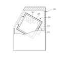
- FIG. 19 and 20 schematically show the oblique drum type washing machine together with the vibration proof support structure of the washing tub unit.
- reference numeral 200 denotes a washing machine main body
- 202 denotes a washing tub unit housed therein
- the washing tub unit 202 is an inner tub that rotates around an obliquely inclined rotation axis as shown in FIG.
- a rotating drum 204 and a water tank 206 as an outer tank containing the rotating drum 204.
- the water tank 206 is provided with a drive motor 208, and the drive motor 208 rotationally drives the rotary shaft 210 of the rotary drum 204.
- reference numeral 212 denotes a suspension spring that forms a part of the vibration isolator, and includes a tension coil spring
- the washing tub unit 202 is elastically suspended by the suspension spring 212.
- Reference numeral 214 denotes an anti-vibration unit that is a main component of the anti-vibration device.
- the washing tub unit 202 is elastically supported from below by the anti-vibration unit 214.
- This anti-vibration unit 214 is formed by unitizing a piston-type oil damper 220, a compression coil spring 222, an upper rubber cushioning member 224, and a lower rubber cushioning member 226.
- the piston-type oil damper 220 has a piston slidably fitted in the cylinder 216, extends a rod 218 downward from the piston, and is based on the sliding movement of the piston in the vertical direction in the drawing.
- the oil in the cylinder 216 is viscously flowed, and the vibration is damped based on the viscous flow.
- a fixing screw shaft 232 extends upward from the cylinder 216, and a nut 234 is screwed therein, and the cylinder 216 and the nut 234 together with the support fitting 228 extending from the washing tub unit 202 are paired with a pair of washers 237 and It is attached and fixed to the support fitting 228 via a rubber cushioning member 224 in a state of being sandwiched between the cushioning members 224-1 and 224-2.
- the rod 218 penetrates the mounting plate 30 provided in the washing machine main body and protrudes downward, and the nut 234 is screwed into the male screw portion at the end thereof, so that the rod 218 is attached to the mounting plate 230 via the lower buffer member 226. It is fixed. Specifically, the plate 236 fixed to the rod 218, the nut 234, and the washer 237 are fixed to the mounting plate 230 so that the pair of buffer members 226-1 and 226-2 are sandwiched between the mounting plate 230.
- the compression coil spring 222 is interposed between the plate 236 fixed to the rod 218 and the plate 238 fixed to the cylinder 216, and the load of the washing tub unit 202 is absorbed by the piston type oil damper by the compression coil spring 222.
- 220 is supported from the lower side through 220 cylinders 216 and upper and lower cushioning members 224 and 226, respectively.
- reference numeral 238 denotes a bottom portion of the washing machine main body 200, and the mounting plate 230 is provided on the bottom portion 238.
- Patent Document 1 Such a problem is pointed out, for example, in Patent Document 1 below. Therefore, in the one disclosed in Patent Document 1, the above problem is solved by using a liquid-filled buffer rubber instead of at least one of the rubber buffer members 224 and 226.
- FIG. 21 shows a specific example.
- a cushioning rubber 240 formed by sealing a viscous fluid (oil) L is provided inside a rubber elastic body 242 having a donut-shaped hollow portion, and a rod During the tilting or plowing movement of 218, the internal viscous fluid L is caused to flow, and the vibration other than the axial direction of the piston type oil damper 220 is damped.
- the oil-filled buffer rubber 240 is installed between the washing tub unit 202 and the bottom of the washing machine body 200 in series with the compression coil spring 222, so Since the entire load applied to the coil spring 222 is always applied to the shock absorbing rubber 240, the shock absorbing rubber 240 operates in a greatly distorted state, which may reduce the vibration damping characteristics of the shock absorbing rubber 240.
- this anti-vibration support structure requires a rubber-made shock absorbing member 224, an oil-filled shock-absorbing rubber 240 and the like in addition to the piston-type oil damper 220 and the compression coil spring 222, which increases the number of required parts. As a result, the assembly process becomes complicated and this increases the cost.
- the oil-filled buffer rubber 240 is installed in series with the compression coil spring 222 and the piston-type oil damper 220, for example, the piston-type oil damper 220 is tilted.
- the displacement of the washing tub unit 202 is not added to the buffer rubber 240 as it is, but the displacement applied to the buffer rubber 240 is smaller than the displacement of the washing tub unit 202.
- the buffer rubber 240 It is difficult for the buffer rubber 240 to exert a sufficient damping action on the tilting direction of the rod 218 or the plowing motion, and as a result, there is a problem that it is difficult to sufficiently damp the vibrations of the washing tub unit 202 in various directions.
- the above-described anti-vibration support structure has also been used conventionally as an anti-vibration support structure for a horizontal drum type washing machine in which a rotating drum is oriented sideways (substantially horizontal).
- This horizontal drum type washing machine also has a problem that the rotating drum swings up and down and left and right, although not as much as the oblique drum type washing machine, and has the same problem as the oblique drum type washing machine.
- the above-mentioned anti-vibration support structure was originally used as the anti-vibration support structure for this horizontal drum type washing machine and was adopted as the anti-vibration support structure for the oblique drum type washing machine. It is the actual situation.
- Patent Document 2 an example in which a vibration isolating support structure of the same type as that using the piston type oil damper is used as a vibration isolating support structure in an oblique drum type washing machine is disclosed in Patent Document 2 below, and in a horizontal drum type washing machine.
- Examples used as the anti-vibration support structure are disclosed in, for example, Patent Document 3 and Patent Document 4 below.
- the present invention is based on the above situation, and the vibration proof support of the laundry tub unit in the drum type washing machine that can well dampen the laundry tub unit in all directions of the vertical direction, the horizontal direction, and the front and rear direction. It was made for the purpose of providing a structure.
- the first aspect of the present invention is a washing machine comprising: a rotating drum as an inner tub that rotates about a rotation axis inclined with respect to the vertical direction; and a water tub as an outer tub that accommodates the rotating drum inside.
- a washing tub unit in a drum type washing machine wherein the tub unit is supported by vibration proofing including a coil spring interposed between the washing tub unit and the washing machine main body and a damper as a vibration damping member.
- the anti-vibration support structure is a three-dimensional damper that attenuates in a three-dimensional direction as the damper, and the damper and the coil spring are connected in parallel between the washing tub unit and the washing machine body. It is characterized by being installed in each.
- the viscous fluid is sealed in the inside of the closed container, and the stirring is provided in a protruding manner in the thin film-like flexible part forming a part of the container.
- a viscous fluid-filled damper that protrudes into the viscous fluid and causes the viscous fluid to viscously flow by the agitating action of the three-dimensional movement of the agitating shaft, thereby damping the coil spring
- the load of the washing tub unit is supported by the coil spring
- the damper is placed at the same location as the coil spring or another It is installed without the coil spring between the washing tub unit and the washing machine main body at one place, and one of the stirring shaft portion and the fixing portion provided at a portion other than the stirring shaft portion of the container is the first. 1 as a fixed part to the washing tub unit, the other Respectively fixed to the washing machine main body as a second fixing portion, the vibration of the washing tub unit is characterized in that no to attenuate at the damper.
- the damper in the second aspect of the present invention, is in a state in which the stirring shaft portion is horizontally oriented with respect to the vertical direction between the vertical wall of the washing machine main body and the washing tub unit.
- the first fixing part is fixed to the washing tub unit, and the second fixing part is fixed to the vertical wall of the washing machine body.
- the vertical dimension of the inner surface of the container in the installed state is larger than the vertical dimension and the dimension perpendicular to the axis of the stirring shaft portion. It is characterized by being.
- the damper according to any one of the second to fourth aspects, wherein the damper closes the peripheral wall portion, a bottom portion that closes one axial opening of the peripheral wall portion, and the other axial opening.
- the flexible shaft and the agitation shaft portion are configured such that the agitation shaft portion extends in the axial direction of the peripheral wall portion at the center of the peripheral wall portion.
- the inner surface shape of the peripheral wall portion is perpendicular to the axis line and the first direction with respect to a dimension in a first direction perpendicular to the axis line of the peripheral wall portion. It is characterized by having a shape with a large dimension in the second direction perpendicular to the axis.
- the damper according to the sixth aspect is characterized in that the shape of the peripheral wall portion is an oval shape including an elliptical shape when viewed in the axial direction.
- the damper in the second aspect, includes a peripheral wall portion, a bottom portion that closes one opening in the axial direction of the peripheral wall portion, and the flexible portion that closes the other opening in the axial direction.
- the stirring shaft portion, the stirring shaft portion extending in the axial direction of the peripheral wall portion at the central portion of the peripheral wall portion, and the peripheral wall portion and the stirring shaft portion have a length in the axial direction. It is characterized by having an elongated shape whose dimension is larger than the dimension in the direction perpendicular to the axis perpendicular to the axis.
- the damper according to the eighth aspect of the present invention is configured so that the damper is in a free-form state before being installed in the washing machine, and the stirring shaft portion is defined by a dimension between the stirring shaft portion and the bottom portion.
- the ratio X / Y between the movable stroke length X in the axial direction and the movable stroke length Y in the direction perpendicular to the axis of the stirring shaft defined by the dimension between the stirring shaft and the peripheral wall is 15/1 to It is within the range of 2/1.
- the thin film-like flexible portion is a cylinder in a direction opposite to the bottom portion from an axial end opposite to the bottom portion of the peripheral wall portion.
- the flexible portion has a cylindrical membrane wall portion and a closing portion that closes the opening at the rising end of the membrane wall portion, and the center of the closing portion
- the stirring shaft part is provided in the part.
- the stirring shaft portion has a tapered tip end portion.
- the damper is installed vertically between the washing tub unit and the bottom of the washing machine body, with the axial direction being the vertical direction,
- the stirring shaft portion is fixed to the washing tub unit as the first fixing portion, and the bottom portion is fixed to the bottom portion of the washing machine body as the second fixing portion.
- the coil spring that elastically supports the washing tub unit from the lower side is arranged in a state surrounding the damper, and the coil spring and the damper are arranged at the same place in the washing tub. It is characterized by being interposed between the unit and the washing machine body.
- the present invention uses a three-dimensional damper that attenuates in a three-dimensional direction as a damper, and is installed in a parallel connection state between the washing tub unit and the washing machine body together with the coil spring. .
- the damper it is possible to support the load of the washing tub unit by the coil spring alone, so that the damper always supports the load of the washing tub unit, that is, the damper is always greatly distorted.
- the shock absorbing rubber 240 is always greatly distorted because the shock absorbing rubber 240 always receives and supports the entire load applied to the coil spring 222 from the washing tub unit 202 as described above.
- the vibration damping action in the state may cause the vibration damping characteristics of the buffer rubber 240 to be reduced.
- the damper since the damper is installed in parallel connection with the coil spring between the washing tub unit and the washing machine body, the damper receives all the load applied to the coil spring from the washing tub unit and supports it. It is possible to support the load of the washing tub unit with a coil spring. Therefore, in the present invention, even if the damper is deformed once by temporarily bending the coil spring, when the coil spring returns to the original shape, the damper also returns to the original shape, and the vibration is attenuated.
- the present invention it is possible to effectively suppress the damper from being permanently distorted and permanently deformed by the load support of the washing tub unit, and therefore the initial good damping action can be maintained over a long period of time.
- the washing tub unit can be maintained and vibration-damping can be achieved.
- the damper is installed between the washing tub unit and the washing machine main body in a parallel relationship with the coil spring, it is possible to cause the displacement of the washing tub unit to act on the damper as it is, Thereby, the damper can be deformed with a large displacement, and the damping action can be exerted greatly. And thereby, it is possible to effectively suppress the shaking and vibration of the washing tub unit.
- the damper is a three-dimensional damper that attenuates in a three-dimensional direction, unlike the above-described piston-type oil damper, that is, a single-axis damper that specifically attenuates an axial displacement. Thus, it effectively prevents vibration and vibration in multiple directions in the washing tub unit.
- the anti-vibration support structure of the present invention when used as an anti-vibration support structure for an oblique drum type washing machine, the multi-directional vibration and vibration of the washing tub unit which has occurred conventionally, that is, the vertical direction, the left-right direction, and the front-rear direction Vibration and vibration can be suppressed satisfactorily.
- the buffer member shown in FIG. 19 and the oil-filled buffer rubber shown in FIG. 21 can be omitted.
- the number of required parts can be reduced, and As a result, the assembly process can be simplified and the required cost can be reduced.
- the three-dimensional damper has a first fixing portion to the washing tub unit side and a second fixing portion to the washing machine body side, and the first fixing portion is relative to the second fixing portion.
- a viscous fluid is enclosed in a sealed container, and a stirring shaft provided in a protruding manner in a thin film-like flexible part forming a part of the container protrudes into the viscous fluid.
- a viscous fluid-filled damper that viscously flows and damps the viscous fluid by the stirring action by the movement of the stirring shaft in the three-dimensional direction can be suitably used.
- one of the stirring shaft portion of the viscous fluid-filled damper and the fixing portion provided at a portion other than the stirring shaft portion of the container is used as the first fixing portion in the washing tub unit, and the other as the second fixing portion in the washing machine body. Each can be fixed.
- the stirring shaft portion can freely move in the three-dimensional direction inside the viscous fluid with the flexible deformation of the thin film-like flexible portion, and the stirring action accompanying the movement By viscously flowing the viscous fluid, it is possible to effectively attenuate the vibration in any of the three-dimensional directions.
- the damper container may be made of an elastic body such as rubber.
- the damper according to claim 2 may be installed vertically between the washing tub unit and the bottom of the washing machine body, that is, vertically with the stirring shaft portion being vertically oriented.
- the damper is installed sideways between the vertical wall of the washing machine body in the vertical direction and the washing tub unit in a state where the stirring shaft portion is sideways with respect to the vertical direction.
- the fixing part can be fixed to the washing tub unit, and the second fixing part can be fixed to the vertical wall of the washing machine body.
- the damper may be such that the dimension in the vertical direction of the inner surface of the container is larger than the dimension in the direction perpendicular to the inner surface of the container in the above-described lateral orientation (claim 4).
- the washing tub unit weighs, for example, about 40 kg when the interior is empty, and the weight increases to about 70 kg when the interior is filled with water and laundry. Along with this, the amount of deflection of the coil spring changes greatly, and the amount of deflection increases when water or laundry is full inside the washing tub, compared to when the inside of the washing tub is empty.
- the washing tub unit changes the vertical position while changing the amount of bending of the coil spring.
- the vertical position (initial position) of the stirring shaft portion of the damper changes relative to the container in accordance with the vertical position change of the washing tub unit.
- the stirring shaft moves around the initial position with a predetermined swing width to cause the viscous fluid to viscously flow and to damp.
- the position where the stirring shaft portion is biased downward in the container due to the weight change of the washing tub unit is set to the initial position.
- the stirring shaft may hit the lower part of the inner surface of the container or the stirring fluid may shake and move at a position close to the lower part of the inner surface of the container.
- the damping performance may be insufficient due to insufficient flow.
- the vertical dimension of the inner surface of the container is increased according to claim 4, such a problem can be avoided and the damping function can be satisfactorily exhibited regardless of the position of the washing tub unit in the vertical direction. Is possible. In this case, it is desirable that the vertical dimension is 1.2 times or more larger than the perpendicular dimension.
- the viscous fluid-filled damper has a peripheral wall, a bottom that closes one opening in the axial direction of the peripheral wall, and the flexible part and the stirring shaft that close the other opening in the axial direction.
- the stirring shaft portion can be configured in a form extending in the axial direction of the peripheral wall portion at the central portion of the peripheral wall portion.
- the damper may be configured such that the inner surface shape of the peripheral wall portion is larger in dimension in the second direction perpendicular to the axis and perpendicular to the first direction than the dimension in the first direction perpendicular to the axis. it can.
- the damper according to claim 6 is also useful in the case where it is installed vertically between the washing tub unit and the bottom of the washing machine body. For example, when one displacement in a direction orthogonal to each other is large and the other displacement is small, the damper is installed with the second direction facing the direction in which the displacement is large. Therefore, the vibration damping action can be satisfactorily exhibited.
- the damper of claim 6 is particularly suitable as a damper used in the vibration isolating support structure of claim 3.
- the damper may have an oval shape in which the shape of the peripheral wall portion includes an elliptical shape when viewed in the axial direction (claim 7).
- the oval shape includes an ellipse shape, two parallel lines of equal length, and an elliptical shape composed of two semicircles that connect one end side and the other end side of each of these parallel lines, as a whole, a continuous curve.
- the shape means an oval shape in which one axis is a major axis and the other axis is a minor axis.
- the thickness of the stirring shaft portion in the damper of claim 2 is set to 15 mm or more.
- the agitation shaft portion is composed of a bottomed cylindrical portion formed integrally with the flexible portion and a shaft body filling the inside thereof, and the shaft body is made of metal having a thickness of ⁇ 10 mm or more. It is desirable that this be integrated with the cylindrical portion by bonding or the like. By doing so, the stirring shaft portion can be made hard and highly rigid, and the viscous fluid can be effectively flowed in a viscous manner when the stirring shaft portion is moved, so that the damping action can be sufficiently performed.
- the damper preferably has a damping coefficient of 0.2 N ⁇ s / mm or more (attenuation coefficient in the direction perpendicular to the axis of the stirring shaft and in the axial direction (the direction of entering the viscous fluid)).
- the damper has a dynamic spring constant in the range of 3 to 20 N / mm (the spring constant in the direction perpendicular to the axis of the stirring shaft and in the axial direction (direction to enter the viscous fluid)).
- the resonance frequency (eigenvalue) of the vibration of a heavy washing tub unit can be made into an appropriate value.
- the minimum thickness of the flexible portion forming the thin film is not more than 8.0% of the thickness of the stirring shaft portion.
- the position of the stirring shaft portion changes with respect to the position at the time of molding in the installed state, and the shape of the thin-walled flexible portion is also deformed from the shape at the time of molding. If a long time elapses in such a state, the flexible part may be permanently deformed when the flexible part is formed of an elastic material.
- the washing tub unit has a large change in weight, and the position in a stationary state changes vertically according to the change in weight.
- the position (initial position) of the stirring shaft portion in the damper and the deformed state of the flexible portion (deformed state at the stationary position) also change.
- the initial position of the stirring shaft portion does not change uniformly and is often located at a certain biased position
- the deformed shape of the flexible portion is changed to a certain biased deformed shape accordingly.
- the film thickness of the flexible part be as thin as 8.0% or less of the thickness of the stirring shaft part.
- the damper is configured such that the damper has a peripheral wall portion, a bottom portion, a flexible portion and a stirring shaft portion extending in the axial direction of the peripheral wall portion at the central portion of the peripheral wall portion, and the peripheral wall portion and the stirring shaft.
- the portion has an elongated shape in which the dimension of the length in the axial direction is larger than the dimension in the direction perpendicular to the axis perpendicular to the axis.
- the damper is disposed in a state where the stirring shaft portion is in a horizontal direction between the vertical wall of the washing machine body in the vertical direction and the washing tub unit.
- the method is different from that of the conventional piston type oil damper shown in FIG.
- the damper of claim 8 since the damper of claim 8 has an elongated shape and can have a large movable stroke length in the axial direction, it is replaced with the conventional piston type oil damper shown in FIG. It becomes possible to install between a tank unit and a washing machine main body.
- the buffer members 224 and 226 required in the conventional anti-vibration support structure shown in FIG. 19 or the oil-filled buffer rubber 240 shown in FIG. 21 can be eliminated.
- the number of required parts can be reduced.
- the vibration in the direction in which the axis of the stirring shaft portion is tilted with respect to the axis of the peripheral wall portion (the twisting direction)
- the twisting direction that is, With respect to the vibration in the direction in which the stirring shaft portion is tilted or rubbed, a large damping action can be exerted by the tilting of the stirring shaft portion, and the vibration in the twisting direction can be satisfactorily suppressed.
- the damper which is not an elongate shape like Claim 8 in the vertical direction instead of the piston type oil damper of the anti-vibration support structure shown in FIG.
- the length of the damper in the axial direction is short, it is difficult to make the movable stroke length in the axial direction of the stirring shaft portion large. Therefore, the change in the stationary position when the weight of the washing tub unit changes It is difficult to respond to.
- the length of the damper in the axial direction is short, it is necessary to provide a mounting member such as a base member on the lower side of the damper when mounting the damper.
- the damper of claim 8 has an elongated shape, it is possible to install the damper without providing a mounting member such as a pedestal member for supporting the damper from below.
- the damper is in a free-form state before being installed in the washing machine, and has a movable stroke length X in the axial direction of the stirring shaft defined by the dimension between the stirring shaft and the bottom of the damper, and the stirring shaft.
- the ratio X / Y to the movable stroke length Y in the direction perpendicular to the axis of the stirring shaft defined by the dimension between the portion and the peripheral wall can be set within the range of 15/1 to 2/1. 9).
- the thin film-like flexible portion of the damper is formed into a shape that rises in a cylindrical shape from the axial end opposite to the bottom of the peripheral wall portion in a direction opposite to the bottom, Has a cylindrical membrane wall portion and a closing portion for closing the opening at the rising end of the membrane wall portion, and the stirring shaft portion is provided at the center of the closing portion.
- the stirring shaft portion can be greatly displaced in the three-dimensional direction by flexibly deforming the cylindrical membrane wall portion, and in various directions. A large damping action can be exhibited.
- the tip end portion of the stirring shaft portion is tapered, and according to the eleventh aspect, the movable stroke in the twisting direction of the stirring shaft portion is effectively increased by the tapered shape. Can do.
- the stirring shaft is used as the first fixed part and the bottom is secondly attached according to claim 12. It can fix to the bottom part of a washing machine main body as a fixing part, and can make a damper installation. By doing in this way, it can replace with the conventional piston type oil damper shown in FIG. 19, and can install a damper in the interposed state between the washing tub unit and the washing machine main body favorably.
- a coil spring that elastically supports the washing tub unit from the lower side is disposed so as to surround the damper, and the coil spring and the damper are interposed between the washing tub unit and the washing machine body at the same location.
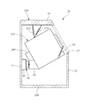
- reference numeral 10 denotes an oblique drum type washing machine, and its configuration is basically the same as that shown in FIG. 19 except for an anti-vibration support structure.
- reference numeral 200 denotes a washing machine body
- 202 denotes a washing tub unit.
- the washing tub unit 202 has a water tub 206 as an outer tub, and a rotating drum as an inner tub is rotatably provided therein.
- Reference numeral 208 denotes a motor that rotationally drives the rotary drum, and reference numeral 238 denotes the bottom of the washing machine main body 200.
- a suspension spring 212 is composed of a tension coil spring.
- the washing tub unit 202 is elastically suspended by the suspension spring 212, and a part of the load is elastically supported by the suspension spring 212. Yes.
- the two suspension springs 212 are arranged at a predetermined angle.
- Reference numeral 12 denotes a front wall of the washing machine body 200
- 14 denotes a rear wall
- 16 denotes an upper wall
- 18 denotes an opening on the front side of the washing machine body 200.
- Reference numeral 20 denotes a coil spring (compression coil spring) that supports the washing tub unit 202 from below.
- the two coil springs 20 are provided on the left and right sides of the washing tub unit 202 (left and right in the front view of the washing tub unit 202). It is arranged in two places. These two coil springs 20 are interposed between a bracket 22 provided in the washing tub unit 202 and a bracket 24 as a base member provided on the bottom 238 of the washing machine body 200.
- the washing tub unit 202 is load-supported from the upper side and the lower side by the suspension spring 212 and the two coil springs 20.
- Reference numeral 26 denotes a damper that attenuates vibration of the washing tub unit 202.
- the bracket 28 is provided on the back surface of the washing tub unit 202, and the washing machine body 200 side, more specifically, the rear wall 14 side that is a vertical wall in the vertical direction. Is interposed between the bracket 30 and the bracket 30.
- the dampers 26 are provided at two places on the left and right with respect to the washing tub unit 202.
- the two coil springs 20 (and the suspension spring 212 that supports the washing tub unit 202 from the upper side) and the two dampers 26 on the back side of the washing tub unit 202 are washed.
- the tank unit 202 and the washing machine body 200 are installed in a parallel connection state.
- the suspension spring 212, the coil spring 20, and the damper 26 constitute a vibration isolator that supports the washing tub unit 202 in a vibration isolating manner.
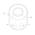
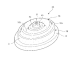
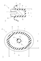
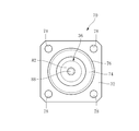
- the damper 26 is a viscous fluid-sealed damper (three-dimensional damper) formed by sealing a viscous fluid inside the hermetic container, and its configuration is specifically shown in FIGS.
- reference numeral 31 denotes a peripheral wall portion of the damper 26, and one opening in the axial direction is closed by a bottom portion 32 as a lid portion.
- the peripheral wall portion 31 and the bottom portion 32 form a container body 34.
- Reference numeral 36 denotes a thin film-like flexible portion that closes the other opening in the axial direction of the peripheral wall portion 31 together with the cylindrical portion 38, and an annular protruding portion 36a that protrudes outward in the axial direction, and a bent portion in the opposite direction.
- the cross-sectional shape is a wavy shape as a whole.
- the flexible portion 36 extends inward (centripetal direction) in the direction perpendicular to the axis from the end of the peripheral wall portion 31 opposite to the bottom portion 32, and a cylindrical portion 38 with a bottom is integrally formed at the center thereof.
- a rigid shaft 40 made of metal is embedded in the inside of the cylindrical portion, and the stirring shaft 42 is constituted by the cylindrical portion 38 and the shaft 40.
- the peripheral wall portion 31, the bottom portion 32, the flexible portion 36, and the cylindrical portion 38 are all formed of a rubber elastic body.
- butyl rubber (IIR) which is a high damping material, is used as the rubber.
- other rubber materials such as natural rubber (NR), acrylonitrile butadiene rubber (NBR), chloroprene rubber (CR), silicone rubber (Q), urethane rubber (U), chlorinated butyl rubber (Cl-IIR), brominated Butyl rubber (Br-IIR), ethylene / propylene rubber (EPDM), or the like can also be used.
- an elastic material other than rubber for example, a styrene thermoplastic elastomer (SBC), an olefin thermoplastic elastomer (TPO), or the like can be used.
- the peripheral wall portion 31, the bottom portion 32, and the like can be entirely or partially made of a hard resin material.
- PP polypropylene
- PA polyamide
- PC polycarbonate
- PMMA acrylic resin
- ABS acrylonitrile-butadiene-styrene resin
- the peripheral wall portion 31, the flexible portion 36, and the cylindrical portion 38 are integrally formed, while the bottom portion 32 is formed separately from these and fixed to the peripheral wall portion 31 by post-bonding. Specifically, after the viscous fluid L is filled in the space formed by the peripheral wall portion 31, the flexible portion 36, and the stirring shaft portion 42, the bottom portion 32 is fixed to the peripheral wall portion 31, and thus the viscosity is contained therein. Fluid L is enclosed.
- high viscosity silicone oil (viscosity is 100,000 cSt) of SH200 manufactured by Toray Dow Corning Co., Ltd. is used as the viscous fluid L.
- the viscous fluid L it is desirable to use a highly viscous fluid having a viscosity in the range of 100,000 cSt to 5 million cSt.
- other viscous fluids such as a silicone compound in which various powders are mixed with silicone oil, and various greases in which powder is mixed with mineral oil can be used.
- the shaft body 40 is integrally fixed to the cylindrical portion 38 by vulcanization bonding, and a part of the shaft body 40 protrudes outward from the flexible portion 36.
- the protruding outer peripheral surface is covered with a coating 50 made of the same material as the flexible portion 36.
- the shaft body 42 is provided with a female screw hole 44 at the center thereof.
- the peripheral wall 31 is integrally provided with an annular flange 43 projecting in the direction perpendicular to the axis (perpendicular to the axis) at the end opposite to the flexible portion 36 in the axial direction.
- the damper 26 is fixed to the bracket 30 on the washing machine body 200 side shown in FIG. 1 at the flange portion 43 as the second fixing portion, and the stirring shaft portion 42 is used as the first fixing portion.
- the stirring shaft 42 is fixed to the bracket 28 on the washing tub unit 202 side.
- the damper 26 is fixed to the bracket 30 so that the flange portion 43 is held by the holding portion 52 on the bracket 30 side while the bottom portion 32 is seated on the bracket 30 side.
- the stirring shaft portion 42 is fixed to the bracket 28 on the washing tub unit 202 side by a bolt 46.
- the agitation shaft portion 42 is fixed to the bracket 28 by the bolt 46 being screwed into the female screw hole 44 of the shaft body 40 via the washer 48.
- the damper 26 is installed between the washing machine main body 200 and the washing tub unit 202 in a state where the damper 26 faces sideways. That is, the damper 26 is installed in a state where the stirring shaft portion 42 and the peripheral wall portion 31 are in a horizontal direction with respect to the vertical direction. Here, both the stirring shaft portion 42 and the peripheral wall portion 31 are installed in the horizontal direction. However, when the damper 26 is installed sideways in this manner, the direction thereof is set in the horizontal direction depending on the mounting location and other circumstances. It may be attached in a state inclined to some extent.
- the damper 26 moves inside the viscous fluid L in the moving direction of the washing tub unit 202 when the washing tub unit 202 moves in the three-dimensional direction. L is stirred to cause viscous flow, and the vibration of the washing tub unit 202 is attenuated based on the viscous flow.
- the stirring shaft portion 42 moves inside the viscous fluid L with the same displacement amount as the displacement of the washing tub unit 202 (strictly, the same displacement amount as that of the damper 26 mounting portion), and the displacement (movement) is large. Based on this, the viscous fluid L is greatly flowed. Therefore, the damping force at that time becomes large. Further, since the stirring shaft portion 42 follows and moves in any of the three-dimensional directions of the washing tub unit 202 to stir the viscous fluid L, any vibration in the vertical direction, the left-right direction, and the front-rear direction of the washing tub unit 202 is achieved. Attenuating action is also highly effective.
- the damper 26 of the present embodiment has an elliptical planar shape. More specifically, the bottom portion 32, the flange portion 43 provided on the peripheral wall portion 31, the outer surface and the inner surface other than the flange portion, and the flexible portion 36 have an elliptical planar shape (however, the stirring shaft portion 42 has a circular shape). ).
- the damper 26 is installed with its long axis directed in the vertical direction in FIG. 6 and its short axis directed in the left-right direction of the washing tub unit 202 (perpendicular to the paper surface).
- the above elliptical shape in the damper 26 has the following meaning.
- the weight of the washing tub unit 202 varies greatly between when the washing tub unit 202 is empty and when the washing tub unit 202 is filled with water and laundry.
- the amount of deflection of the suspension spring 212 and the coil spring 20 changes greatly, and the position (stationary position) of the washing tub unit 202 changes greatly up and down.
- the position (initial position) of the stirring shaft portion 42 in the damper 26 also changes greatly in the vertical direction.
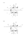
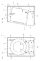
- FIG. 7 shows how the initial position of the stirring shaft portion 42 changes as the weight of the washing tub unit 202 changes.
- (A) shows the stirring shaft portion 42 in the initial position when the washing tub unit 202 is the lightest
- (B) shows the stirring shaft when the washing tub unit 202 is the heaviest. This represents a state in which the part 42 is in the initial position.
- the stirring shaft portion 42 is greatly depressed downward from the position shown in FIG.
- the agitation shaft portion 42 is required to move within the viscous fluid L with a predetermined swing width under each initial position to exhibit a required damping characteristic.
- the peripheral wall portion 31, particularly the inner surface shape thereof is elliptical so as to increase the size of the peripheral wall portion 31 in the up-down direction in which the initial position of the stirring shaft portion 42 changes, specifically, the inner surface size thereof. Regardless of the change in the initial position of the stirring shaft portion 42, the stirring shaft portion 42 is moved within the viscous fluid L by a required amount of vibration so as to satisfactorily attenuate.
- the stirring shaft portion 42 of the peripheral wall portion 31 Since the stirring shaft portion 42 moves within the viscous fluid L with a predetermined swing width, the stirring shaft portion 42 contacts the lower portion of the peripheral wall portion 31 or does not contact the peripheral wall portion. By moving at a position close to 31, the stirring action on the viscous fluid L is reduced, which may result in insufficient damping characteristics.
- the damper 26 is wasted. It becomes large shape.
- the damper 26 is formed into an elliptical shape so that a required damping characteristic can be obtained without unnecessarily increasing the size of the damper 26.
- the damper 26 has an elliptical shape, but the damper 26 may have a shape approximate to the elliptical shape instead of a strict elliptical shape.
- the shape of the damper 26 is rectangular, a corner portion is formed in the flexible portion 36, stress concentration occurs there, causing a problem in strength of the flexible portion 36. Not desirable.
- the thickness t 1 of the thin-walled flexible portion 36 is 1.5 mm
- the thickness t 2 of the bottom portion 31 is 3 mm
- the height dimension h 1 of the peripheral wall portion 31 is 36 mm.
- the ratio is 1.33, but this ratio can be changed. However, it is desirable to set it to 1.20 or more.
- the ratio t 1 / d 7 6.25% between the outer diameter d 7 of the stirring shaft portion 42 and the thickness t 1 of the thin-walled flexible portion 36.
- the damper 26 has a damping coefficient of 0.3 N ⁇ s / mm and a dynamic spring constant of 5 N / mm.
- the damper 26 since the damper 26 is installed in parallel connection with the coil spring 20 between the washing tub unit 202 and the washing machine body 200, all of the addition from the washing tub unit 202 to the coil spring 20 is performed. The load is not received by the damper 26 and supported, and the load of the washing tub unit 202 can be supported by the suspension spring 212 and the coil spring 20 alone. Therefore, in this embodiment, even if the damper 26 is temporarily deformed due to the temporary bending of the coil spring 26, the damper 26 also returns to the original shape when the coil spring 20 is restored to the original shape, and the vibration damping action. To do.
- the damper 26 can be prevented from being permanently deformed by the load support of the washing tub unit 202, and the initial good damping action can be maintained over a long period of time. Can act.
- the damper 26 is installed between the washing tub unit 202 and the washing machine body 200 in a parallel relationship with the coil spring 20, the displacement of the washing tub unit 202 is applied to the damper 26 with the same size.
- the damper 26 can be deformed with a large displacement, and the damping action can be exerted greatly. As a result, shaking and vibration of the washing tub unit 202 can be effectively suppressed.
- the damper 26 is a three-dimensional damper that attenuates in a three-dimensional direction, like the above-described piston-type oil damper, that is, a one-axis damper that specifically attenuates an axial displacement. Unlikely, the vibration and vibration in all directions in the washing tub unit 202 can be effectively prevented.
- the vibration isolating support structure of the present embodiment it is possible to omit the buffer member shown in FIG. 19, the oil-filled buffer rubber shown in FIG. 21, etc., thereby reducing the number of required parts. Accordingly, the assembly process can be simplified and the required cost can be reduced.
- FIG. 8 shows another embodiment of the present invention.
- the damper 26 is directed upward in the vertical direction, more specifically, with the flexible portion 36 facing upward, the axial direction of the peripheral wall portion 31 and the stirring shaft portion 42 are oriented vertically so that the coil spring
- the brackets 22 and 24 are fixed to the brackets 22 and 24 in a parallel connection state.
- the other points are basically the same as those in the above embodiment.
- the elliptical damper 26 may be used as the damper 26 in this case.
- the damper 26 since the weight of the washing tub unit 202 changes, the initial position of the stirring shaft portion 42 does not change in the direction perpendicular to the axis with respect to the peripheral wall portion 31, so this FIG.
- a circular planar shape specifically, a shape in which the shape of the inner surface of the peripheral wall portion 31 forms a circular shape can be used.
- FIG. 9 shows still another embodiment of the present invention.
- a suspension spring 54 is used, and the load of the washing tub unit 202 is supported by another suspension spring 212 and the suspension spring 54. This is an example.
- FIG. 10 shows still another embodiment of the present invention.
- the washing tub unit 202 is load-supported by the suspension spring 212 without using the coil spring 20 in the embodiment of FIG.
- the suspension tub unit 202 is supported by the suspension spring 212 alone. It can be so.
- Vibration analysis is performed for each of the conventional anti-vibration support structure shown in FIG. 19 (FIG. 11A) and the anti-vibration support structure of the embodiment shown in FIG. 10 (FIG. 11B). The effect was verified.
- ADAMS software manufactured by MSC Software was used as vibration analysis software.
- the vibration analysis was performed on the position X of the upper front end of the washing tub unit 202 shown in FIG. Further, assuming the case where the laundry is unevenly distributed in the rotating drum, vibration analysis was performed by setting conditions when the eccentric mass M having a mass of 200 g was positioned at the front end portion and the rear end portion of the rotating drum.
- the input items and conditions were as follows.
- a vibration analysis model a washing tub unit 202, two suspension springs (tensile coil springs) 212 are provided above the washing tub unit 202, and a vibration isolation unit 214 (FIG. 11A) is provided below the washing tub unit 202.
- a vibration isolation unit 214 FIG. 11A
- molds was created.
- the washing tub unit 202 includes a rotating drum (inner tub) 204, an eccentric mass M mounted on the inner side of the rotating drum 204, and a water tub (outer tub) 206.
- the rotating drum 204 and the water tank 206 are connected to each other at the center of the circle at the rear end to provide a degree of freedom in the drum rotating direction.
- the center of gravity, moment of inertia, and mass (10 kg of rotating drum and 30 kg of water tank) were input, respectively.
- the eccentric mass M a mass (a mass of 200 g at the inner front end of the rotating drum or a mass of 200 g at the inner rear end of the rotating drum) was input.
- the anti-vibration unit 214 includes a piston-type oil damper 220, a compression coil spring 222 below the damper, a rubber cushioning member 224 at the top of the damper, and a rubber cushioning member 226 at the bottom of the damper.
- rad and c 10,000 N ⁇ mm ⁇ s / rad were input.
- the dynamic spring constant is a value under the following dynamic displacement condition.
- Measurement conditions Suspension spring: Frequency 5Hz, Displacement ⁇ 10mm Piston type oil damper: 5Hz, ⁇ 10mm Compression coil spring: 5Hz, ⁇ 10mm Buffer member (axis, axis perpendicular direction): 5 Hz, ⁇ 0.1 mm Buffer member (rotating direction): 5Hz, ⁇ 1deg Viscous liquid-filled damper (axis, direction perpendicular to axis): 5 Hz, ⁇ 10 mm Viscous liquid filled damper (rotating direction): 5 Hz, ⁇ 1 deg
- a vibration curve B represents a vibration analysis result in the conventional vibration-proof support structure shown in FIG. 19, and a vibration curve A represents a vibration analysis result in the vibration-proof support structure of the embodiment of FIG.
- Both amplitudes on the vertical axis mean all amplitudes.
- the vibration amplitude of the washing tub unit 202 is suppressed to be small. Further, in all directions, the peak at the primary resonance is suppressed in the vibration-proof support structure of the embodiment of FIG.
- FIG. 13 shows a comparison of vibration analysis results and measured values for the vibration-proof support structure shown in FIG. 19 (vibration curve C in the figure shows the measured values).
- the actual measurement value was obtained by measuring the acceleration with an acceleration sensor attached to the position X and integrating the acceleration. As shown in FIG. 13, the calculation result by vibration analysis is close to the actual measurement value, and the actual measurement can be substantially reproduced.
- FIG. 14 shows another example of the damper.
- reference numeral 70 denotes a damper.
- the damper 70 includes a cylindrical peripheral wall portion 31, a bottom portion 32 serving as a lid portion for closing one axial opening (opening at the lower end in the drawing) of the peripheral wall portion 31, and these peripheral walls.
- a container main body 34 composed of a portion 31 and a bottom portion 32; a thin-film flexible portion 36 extending from the upper end of the peripheral wall portion 31 in the figure; and a flexible portion 36 at the center of the flexible portion 36.
- a stirring shaft portion 42 comprising a rigid shaft body 40 made of metal embedded in the cylindrical portion 38 and the cylindrical portion 38, and a viscous fluid L enclosed in an airtight container formed thereby. It is the same as that of the damper 26 of the said embodiment at the point which has.
- the damper 70 of this example is different from that of the above embodiment in the following points. That is, in this embodiment, the peripheral wall 31 of the damper 70 is made of resin (here, a polyamide resin containing 50% by mass of glass fiber), and the shape thereof is in the vertical direction in the drawing (vertical direction in the drawing). It is an elongated shape.
- h 2 is the axis perpendicular direction perpendicular to the axis of the dimension (outer diameter) larger elongated than d 11 Yes.
- the peripheral wall 31 is formed with a coating 72 that is integrally formed with the flexible portion 36 using the same material as the flexible portion 36 over the entire inner surface thereof.
- the bottom 32 is also made of the same resin as that of the peripheral wall 31, and the lower end of the peripheral wall 31 in the figure and the bottom 32 are joined to each other by ultrasonic welding. More specifically, a flange portion 74 is formed on the lower end portion of the peripheral wall portion 31 in the figure, and the flange portion 74 projects in an annular shape outward in the direction perpendicular to the axis, while the bottom portion 32 is provided with an annular protrusion 76 on the upper surface in the drawing.
- the flange portion 74 and the bottom portion 32 are ultrasonically welded and joined in a state where the flange portion 74 is fitted in a recess formed inside the protrusion 76. The joining by the ultrasonic welding is performed after the viscous fluid L is injected into the container body 34.
- the bottom portion 32 has a quadrangular shape (here, square shape) in plan view having a larger outer shape than the peripheral wall portion 31, and the four corner portions are provided with a plate.
- Fixing holes 78 penetrating in the thickness direction are provided, and in these fixing holes 78, the bottom portion 32 is fastened to the bottom portion 238 of the washing machine body 200 with a screw fastener. That is, in this embodiment, the damper 70 is fixed to the washing machine main body 200 with the bottom portion 32 as the second fixing portion.
- the stirring shaft portion 42 also has an elongated shape that is long in the vertical direction in the drawing.
- the length dimension (height dimension) h 3 in the upper and lower axial directions in the drawing is an elongated shape larger than the dimension perpendicular to the axis (outer diameter) d 9 .
- the flexible portion 36 extends as it is from the one end in the axial direction of the peripheral wall portion 31 toward the inside in the direction perpendicular to the axis (toward the centripetal direction) while forming a wave shape.
- the flexible portion 36 has a cylindrical shape from the axial end (upper end in the drawing) of the peripheral wall portion 31 on the side opposite to the bottom 32 to the upper side in the drawing opposite to the bottom 32.
- the flexible portion 36 has a cylindrical (substantially cylindrical) membrane wall portion 80 having a predetermined axial dimension, and a rising end (upper end in the figure) of the membrane wall portion 80.
- the agitation shaft portion 42 is provided at the center of the closing portion 82.
- the flexible portion 36 has a tapered shape inclined at an angle ⁇ , the outer diameter of which gradually decreases as the outer shape of the flexible portion 36 moves upward in the drawing, and the thickness of the membrane wall portion 80 is As it moves from the middle up, it gradually thickens.
- the size h 5 of the membrane wall portion 80 is changed by other overall size of the damper 70, the dimensions h 5 In either case, it is desirable that not less than 25 mm.
- the upper end surface of the peripheral wall portion 31 in the figure is covered with a coating 83 formed integrally with the flexible portion 36 from the same material.
- the damper 70, the whole axial dimension (height) is the h 6.
- h 6 162.5 mm.
- the damper 70 of the present embodiment as a whole has an elongated shape in the vertical direction in the figure, and as a result, is defined by the dimension between the stirring shaft portion 42 and the bottom portion 32 in a free-form state.
- a large movable stroke length X in the axial direction of the stirring shaft portion 42 is secured.
- 50 mm is secured as the movable stroke length X in the axial direction (vertical direction in the drawing) of the stirring shaft portion 42 here.
- the tip end portion (lower end portion in the drawing) 84 of the stirring shaft portion 42 has a tapered shape that tapers downward in the drawing.
- both the shaft body 40 and the cylindrical portion 42 are tapered in the same direction.
- a front end surface (lower end surface in the figure) 86 of the cylindrical portion 38 is a flat surface in the direction perpendicular to the axis. Note that the thickness of the cylindrical portion 38 gradually increases toward the tip, and correspondingly, the outer diameter of the shaft body 40 gradually decreases toward the tip.
- the shaft body 40 constituting the stirring shaft portion 42 protrudes upward from the flexible portion 36 at the upper end side in the drawing, and a male screw portion 88 is provided at the protruding portion.
- the extended support fitting 228 is fixed by a nut 90.
- the damper 26 can be installed using a space prepared for the piston type oil damper 214.
- the length of the damper 26 in the axial direction (vertical direction in the drawing) is short, and it is difficult to make the movable stroke length of the stirring shaft portion 42 in the vertical direction in the drawing large.
- the damper 26 since it is difficult for the damper 26 to have a large movable stroke length in the axial direction, it is difficult to cope with a change in the stationary position when the weight of the washing tub unit 202 changes. Further, since the length of the damper 26 in the axial direction is short, it is necessary to provide a bracket 24 as a pedestal member on the lower side when the damper 26 is attached.
- the damper 70 of this embodiment has an elongated shape in the axial direction, and the movable stroke length X of the stirring shaft portion 42 in the axial direction can be increased, the conventional piston type oil shown in FIG. This can be installed between the washing tub unit 202 and the washing machine main body 200 in a form replacing the damper 220 (without providing the bracket 24 as a base member as shown in FIG. 10).
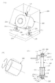
- FIG. 16 shows a specific installation structure at that time.
- the damper 70 is oriented vertically (vertically), and is interposed between the washing tub unit 202 and the bottom 238 of the washing machine body 200, and the stirring shaft portion 42 serves as a first fixed portion, which is used as the washing tub unit. 202, and the bottom portion 32 of the damper 70 is used as a second fixing portion, which is fixed to the bottom portion 238 of the washing machine body 200, and the washing tub unit 202 and the bottom portion 238 of the washing machine body 200 are connected by the damper 70. It is out.
- a coil spring (compression coil spring) 90 that elastically supports the washing tub unit 202 from the lower side is disposed so as to surround the damper 70, and the coil spring 90 and the damper 70 are washed with the washing tub unit 202 and the laundry at the same place. It is installed in parallel connection with the bottom 238 of the machine body 200.
- the damper 70 of the present embodiment can be installed by effectively utilizing the space previously occupied by the piston-type oil damper, and a special space for installing the damper 70 can be provided at another location. It is possible to eliminate the need to secure the system. Moreover, the conventional piston type oil damper only damps in the axial direction, but the damper 70 of this embodiment can damp in the three-dimensional direction, and can effectively suppress multidirectional vibration.
- the buffer members 224 and 226 required in the conventional anti-vibration support structure shown in FIG. 19 or the oil-filled buffer rubber 240 shown in FIG. 21 can be eliminated.
- the number of required parts can be reduced.
- the axial length of the stirring shaft portion 42 can be increased, the direction in which the axis of the stirring shaft portion 42 is tilted with respect to the axis of the peripheral wall portion 31 (P in FIG. 14).
- the vibration of the stirring shaft portion 42 can be exerted with a large damping action against the vibration of the stirring shaft portion 42, that is, the vibration of the stirring shaft portion 42 in a tilting or rubbing motion. can do.
- the stirring shaft portion 42 can be greatly displaced in the three-dimensional direction by flexibly deforming the cylindrical membrane wall portion 80, and various A large damping effect can be exhibited in any direction.
- the tip end portion 84 of the stirring shaft portion 42 is tapered, the movable stroke of the stirring shaft portion 42 in the twisting direction can be further effectively increased.
- FIG. 17 shows another embodiment.
- the laundry tub unit 202 is load-supported only by a suspension spring 92 made of a tension coil spring.
- the installation structure of the damper 70 is the same as that shown in FIG.
- the damper 70 shown in FIG. 14 is merely an example of an elongated damper, and is configured to be larger as shown in FIG. 18, and the dimensions in FIG.
- the dimensions of d 9 , d 10 , d 11 , h 2 , h 3 , h 4 , h 5 , h 6, etc. can be changed as appropriate, or the internal thread portion 94 is provided on the shaft body 40 of the stirring shaft portion 42. It is also possible to fix the stirring shaft portion 42 to the support fitting 228 with the bolt 96 at the female screw portion 94.
- the damper 70 can be configured in another form different from the form shown in FIGS.
- the viscous fluid sealed inside the container is used as a damper.
- the viscous fluid is damped by the stirring action by the stirring shaft portion.
- this is merely an example, and the present invention is three-dimensional in various other forms. It is possible to constitute a vibration-proof support structure using a damper.
- a liquid chamber is provided inside a container made of a rubber elastic body, a viscous fluid L is sealed therein, and the container of the rubber elastic body is deformed in accordance with the displacement of the washing tub unit 202 in the three-dimensional direction. It is also possible to use a damper having a damping action by viscously flowing a viscous fluid based on the above.
- this invention is an example which applied this invention as an anti-vibration support structure of an oblique drum type washing machine
- this invention can also be applied as an anti-vibration support structure of a horizontal drum type washing machine with a rotating drum facing sideways.
- the present invention can be configured in various forms without departing from the spirit of the present invention.
Landscapes
- Engineering & Computer Science (AREA)
- Textile Engineering (AREA)
- Main Body Construction Of Washing Machines And Laundry Dryers (AREA)
Abstract
【課題】上下方向,左右方向,前後方向の多方向に亘って良好に洗濯槽ユニットを防振することのできるドラム式洗濯機における洗濯槽ユニットの防振支持構造を提供する。【解決手段】傾斜した回転軸心回りに回転する内槽としての回転ドラムと、外槽としての水槽(206)とを備えた洗濯槽ユニット(202)を、洗濯槽ユニット(202)と洗濯機本体(200)との間に介在させたコイルばねと振動減衰部材としてのダンパとを含む防振装置にて防振支持する洗濯槽ユニット(202)の防振支持構造において、3次元方向に減衰作用する3次元ダンパ(26)を用い、洗濯槽ユニット(202)と洗濯機本体(200)との間にダンパ(26)とコイルばね(20)とを互いに並列接続状態にそれぞれ設置する。
Description
この発明は、回転ドラムの回転軸心が垂直方向に対して傾斜した所謂斜めドラム式の洗濯機に適用して特に好適なドラム式洗濯機における洗濯槽ユニットの防振支持構造に関する。
ドラム式洗濯機として、垂直方向に対して傾斜した回転軸心回りに回転する内槽としての回転ドラムと、回転ドラムを内側に収容する外槽としての水槽とを備えた洗濯槽ユニットを備え、回転ドラム内に洗濯物を入れて回転ドラムを回し、洗濯,すすぎ,脱水の各工程を行う所謂斜めドラム式洗濯機が従来公知である。
この斜めドラム式洗濯機では、洗濯槽ユニットと洗濯機本体との間に介在させたコイルばねと、振動減衰部材としてのダンパとを含む防振装置にて洗濯槽ユニットを防振支持するようになしている。
この斜めドラム式洗濯機では、洗濯槽ユニットと洗濯機本体との間に介在させたコイルばねと、振動減衰部材としてのダンパとを含む防振装置にて洗濯槽ユニットを防振支持するようになしている。
図19及び図20はこの斜めドラム式洗濯機を、洗濯槽ユニットの防振支持構造とともに模式的に示している。
図において200は洗濯機本体、202はその内部に納められた洗濯槽ユニットで、この洗濯槽ユニット202は、図20に示しているように、斜めに傾斜した回転軸心回りに回転する内槽としての回転ドラム204と、これを内側に収容した外槽としての水槽206とを有している。
水槽206には駆動モータ208が設けられており、この駆動モータ208により、回転ドラム204の回転軸210が回転駆動される。
図において200は洗濯機本体、202はその内部に納められた洗濯槽ユニットで、この洗濯槽ユニット202は、図20に示しているように、斜めに傾斜した回転軸心回りに回転する内槽としての回転ドラム204と、これを内側に収容した外槽としての水槽206とを有している。
水槽206には駆動モータ208が設けられており、この駆動モータ208により、回転ドラム204の回転軸210が回転駆動される。
図19において、212は防振装置の一部をなす吊りばねで、引張コイルばねから成っており、この吊りばね212によって洗濯槽ユニット202が弾性的に吊持されている。
214は防振装置の主体をなす防振ユニットで、洗濯槽ユニット202は、この防振ユニット214によって下側から弾性的に支持されている。
この防振ユニット214は、ピストン式オイルダンパ220と、圧縮コイルばね222と、上部のゴム製の緩衝部材224,下部のゴム製の緩衝部材226をユニット化したものである。
214は防振装置の主体をなす防振ユニットで、洗濯槽ユニット202は、この防振ユニット214によって下側から弾性的に支持されている。
この防振ユニット214は、ピストン式オイルダンパ220と、圧縮コイルばね222と、上部のゴム製の緩衝部材224,下部のゴム製の緩衝部材226をユニット化したものである。
ピストン式オイルダンパ220は、シリンダ216の内部にピストンを摺動可能に嵌合して、そのピストンからロッド218を図中下向きに延び出させ、そしてピストンの図中上下方向の摺動運動に基づいて、シリンダ216内部のオイルを粘性流動させ、その粘性流動に基づいて振動を減衰作用する。
シリンダ216からは上向きに固定用のねじ軸232が延び出していて、そこにナット234がねじ込まれ、シリンダ216がナット234とともに、洗濯槽ユニット202から延び出した支持金具228を一対のワッシャ237及び緩衝部材224-1と224-2とで挟み込む状態にゴム製の緩衝部材224を介して支持金具228に取付固定されている。
一方ロッド218は、洗濯機本体に設けられた取付プレート30を貫通して下向きに突き出し、その端部の雄ねじ部にナット234がねじ込まれることで、下部の緩衝部材226を介して取付プレート230に固定されている。
詳しくは、ロッド218に固定のプレート236と、ナット234及びワッシャ237とで一対の緩衝部材226-1,226-2を取付プレート230に挟み込む状態に、取付プレート230に固定されている。
詳しくは、ロッド218に固定のプレート236と、ナット234及びワッシャ237とで一対の緩衝部材226-1,226-2を取付プレート230に挟み込む状態に、取付プレート230に固定されている。
そしてロッド218に固定のプレート236と、シリンダ216に固定のプレート238との間に上記の圧縮コイルばね222が介装され、洗濯槽ユニット202の荷重がこの圧縮コイルばね222により、ピストン式オイルダンパ220のシリンダ216及び上部と下部のそれぞれの緩衝部材224,226を介して下側から支持されている。
尚図19において238は洗濯機本体200の底部で、上記取付プレート230はこの底部238に設けられている。
尚図19において238は洗濯機本体200の底部で、上記取付プレート230はこの底部238に設けられている。
ところがこの防振支持構造では、ピストン式オイルダンパ220による大きな減衰が、その軸方向にしか得られず、それ以外の方向の振動が十分に減衰されない問題がある。
上記の斜めドラム式洗濯機の場合、回転ドラムが斜めに傾いていることから、回転ドラム内で洗濯物が偏在し易く、即ち回転ドラムに対して偏荷重がかかり易く、しかも回転ドラムが斜めの軸心回りに回転することによって、特に脱水工程の初期の起動時(300rpm程度までの低速回転域)に図19(B)に示すように洗濯槽ユニット202が上下,左右,前後の全方向に大きく振れ回り(例えば各方向に25mm程度の振れ)、大振幅で振動を生じ易い。
しかるに図19に示す防振支持構造では、ピストン式オイルダンパ220による減衰が軸方向にしか得られないため、洗濯槽ユニット202の多方向の振れ回りを十分に抑制することが難しい問題があった。
上記の斜めドラム式洗濯機の場合、回転ドラムが斜めに傾いていることから、回転ドラム内で洗濯物が偏在し易く、即ち回転ドラムに対して偏荷重がかかり易く、しかも回転ドラムが斜めの軸心回りに回転することによって、特に脱水工程の初期の起動時(300rpm程度までの低速回転域)に図19(B)に示すように洗濯槽ユニット202が上下,左右,前後の全方向に大きく振れ回り(例えば各方向に25mm程度の振れ)、大振幅で振動を生じ易い。
しかるに図19に示す防振支持構造では、ピストン式オイルダンパ220による減衰が軸方向にしか得られないため、洗濯槽ユニット202の多方向の振れ回りを十分に抑制することが難しい問題があった。
こうした問題は、例えば下記特許文献1にも指摘されている。
そこで特許文献1に開示のものでは、ゴム製の緩衝部材224,226の少なくとも一方に代えて、液体封入式の緩衝ゴムを用いることで上記の問題の解決を図っている。
そこで特許文献1に開示のものでは、ゴム製の緩衝部材224,226の少なくとも一方に代えて、液体封入式の緩衝ゴムを用いることで上記の問題の解決を図っている。
図21はその具体例を示している。
図に示しているようにここでは下部の緩衝部材226に代えて、ドーナツ環状の中空部を有するゴム弾性体242の内部に粘性流体(オイル)Lを封入して成る緩衝ゴム240を設け、ロッド218の傾動或いはすりこぎ運動時に、内部の粘性流体Lを流動させ、ピストン式オイルダンパ220の軸方向以外の振動を減衰作用させるようになしている。
図に示しているようにここでは下部の緩衝部材226に代えて、ドーナツ環状の中空部を有するゴム弾性体242の内部に粘性流体(オイル)Lを封入して成る緩衝ゴム240を設け、ロッド218の傾動或いはすりこぎ運動時に、内部の粘性流体Lを流動させ、ピストン式オイルダンパ220の軸方向以外の振動を減衰作用させるようになしている。
しかしながらこの防振支持構造では、オイル封入式の緩衝ゴム240が、圧縮コイルばね222と直列で洗濯槽ユニット202と洗濯機本体200の底部との間に設置されているため、洗濯槽ユニット202からコイルばね222に掛かる全荷重が常時緩衝ゴム240に加わって、緩衝ゴム240が大きく歪んだ状態で動作することとなり、そのことが緩衝ゴム240による振動減衰特性を低下させてしまう恐れがある。
またこの防振支持構造では、ピストン式オイルダンパ220及び圧縮コイルばね222の他に、ゴム製の緩衝部材224,オイル封入式の緩衝ゴム240等が必要で、所要部品点数が多くなり、それに伴って組立工程も複雑化し、このことがコストを増大させる要因となる。
加えてこの防振支持構造では、オイル封入式の緩衝ゴム240が、圧縮コイルばね222,ピストン式オイルダンパ220と直列状態で設置されているために、例えばピストン式オイルダンパ220を傾動させるような変位が洗濯槽ユニット202に生じたときに、洗濯槽ユニット202の変位がそのままの大きさで緩衝ゴム240に加わらず、緩衝ゴム240に加わる変位が洗濯槽ユニット202の変位よりも小さくなるため、緩衝ゴム240がロッド218の傾動方向或いはすりこぎ運動に対し十分な減衰作用を発揮することが難しく、結果として洗濯槽ユニット202の様々な方向の振動を十分に減衰することが難しい問題がある。
上記の防振支持構造は、回転ドラムが横向き(略水平向き)をなす横ドラム式洗濯機の防振支持構造としても従来から用いられている。
この横型ドラム式洗濯機においても、斜めドラム式洗濯機ほどではないものの回転ドラムが上下,左右方向に振れ回る問題があり、斜めドラム式洗濯機と同様の課題を有する。
上記の防振支持構造は、もともとはこの横ドラム式洗濯機における防振支持構造として用いられていたものを、斜めドラム式洗濯機の防振支持構造として採用したもので、以来現在に到っているのが実情である。
例えば、上記のピストン式オイルダンパを用いたのと同種の防振支持構造を斜めドラム式洗濯機における防振支持構造として用いた例が下記特許文献2に開示され、また横ドラム式洗濯機における防振支持構造として用いた例が例えば下記特許文献3,下記特許文献4等に開示されている。
この横型ドラム式洗濯機においても、斜めドラム式洗濯機ほどではないものの回転ドラムが上下,左右方向に振れ回る問題があり、斜めドラム式洗濯機と同様の課題を有する。
上記の防振支持構造は、もともとはこの横ドラム式洗濯機における防振支持構造として用いられていたものを、斜めドラム式洗濯機の防振支持構造として採用したもので、以来現在に到っているのが実情である。
例えば、上記のピストン式オイルダンパを用いたのと同種の防振支持構造を斜めドラム式洗濯機における防振支持構造として用いた例が下記特許文献2に開示され、また横ドラム式洗濯機における防振支持構造として用いた例が例えば下記特許文献3,下記特許文献4等に開示されている。
尚、本発明に対する先行技術として下記特許文献5,特許文献6,特許文献7に粘性流体封入ダンパが開示されている。
但しこれら特許文献には本発明の課題及びその解決手段については開示されていない。
但しこれら特許文献には本発明の課題及びその解決手段については開示されていない。
本発明は以上のような事情を背景とし、上下方向,左右方向,前後方向の全方向に亘って良好に洗濯槽ユニットを防振することのできるドラム式洗濯機における洗濯槽ユニットの防振支持構造を提供することを目的としてなされたものである。
而して請求項1のものは、垂直方向に対して傾斜した回転軸心回りに回転する内槽としての回転ドラムと、該回転ドラムを内側に収容する外槽としての水槽とを備えた洗濯槽ユニットを、該洗濯槽ユニットと洗濯機本体との間に介在させたコイルばねと、振動減衰部材としてのダンパとを含む防振装置にて防振支持する、ドラム式洗濯機における洗濯槽ユニットの防振支持構造であって、前記ダンパとして3次元方向に減衰作用する3次元ダンパを用い、前記洗濯槽ユニットと前記洗濯機本体との間に該ダンパと前記コイルばねとを互いに並列接続状態にそれぞれ設置したことを特徴とする。
請求項2のものは、請求項1において、前記ダンパとして、密閉容器の内部に粘性流体を封入して成り、該容器の一部をなす薄肉膜状の可撓部に突出状に設けた撹拌軸部を該粘性流体の内部に突出させて、該撹拌軸部の3次元方向の移動による撹拌作用で該粘性流体を粘性流動させて減衰作用する粘性流体封入ダンパを用い、前記コイルばねを該ダンパを介さずに前記洗濯槽ユニットと洗濯機本体との間に設置して、該コイルばねにて該洗濯槽ユニットの荷重支持を担わせるとともに、該ダンパを該コイルばねと同一個所又は別の個所で前記洗濯槽ユニットと洗濯機本体との間に前記コイルばねを介さずに設置して、前記撹拌軸部と前記容器の該撹拌軸部以外の部位に設けた固定部との一方を第1固定部として前記洗濯槽ユニットに、他方を第2固定部として前記洗濯機本体にそれぞれ固定し、前記洗濯槽ユニットの振動を該ダンパにて減衰させるようになしたことを特徴とする。
請求項3のものは、請求項2において、前記ダンパを、前記洗濯機本体の上下方向の縦の壁と前記洗濯槽ユニットとの間において前記撹拌軸部が上下方向を基準として横向きをなす状態に配置して、前記第1固定部を該洗濯槽ユニットに、前記第2固定部を前記洗濯機本体の前記縦の壁に固定したことを特徴とする。
請求項4のものは、請求項3において、前記ダンパは、前記設置状態で前記容器の内面の上下方向の寸法が、該上下方向及び前記撹拌軸部の軸線と直角方向の寸法よりも大きくしてあることを特徴とする。
請求項5のものは、請求項2~4の何れかにおいて、前記ダンパは、周壁部と、該周壁部の軸線方向の一方の開口を閉鎖する底部と、該軸線方向の他方の開口を閉鎖する前記可撓部及び撹拌軸部とを有し、該撹拌軸部が該周壁部の中心部において該周壁部の軸線方向に延びる形態をなしていることを特徴とする。
請求項6のものは、請求項5において、前記ダンパは、前記周壁部の内面形状が、該周壁部の前記軸線と直角な第1方向の寸法に対し、該軸線と直角且つ該第1方向と直角な第2方向の寸法が大きい形状となしてあることを特徴とする。
請求項7のものは、請求項6において、前記ダンパは、前記周壁部の形状が、前記軸線方向視において楕円形状を含むオーバル形状をなしていることを特徴とする。
請求項8のものは、請求項2において、前記ダンパは、周壁部と、該周壁部の軸線方向の一方の開口を閉鎖する底部と、該軸線方向の他方の開口を閉鎖する前記可撓部及び撹拌軸部とを有し、該撹拌軸部が該周壁部の中心部において該周壁部の軸線方向に延びる形態をなしており、且つ前記周壁部及び撹拌軸部は、軸線方向の長さの寸法が該軸線と直角な軸直角方向の寸法よりも大きい細長形状をなしていることを特徴とする。
請求項9のものは、請求項8において、前記ダンパは、前記洗濯機への設置前の自由形状状態で、前記撹拌軸部と前記底部との間の寸法で規定される該撹拌軸部の軸線方向の可動ストローク長Xと、該撹拌軸部と前記周壁部との間の寸法で規定される該撹拌軸部の軸直角方向の可動ストローク長Yとの比率X/Yが15/1~2/1の範囲内であることを特徴とする。
請求項10のものは、請求項8,9の何れかにおいて、薄肉膜状の前記可撓部が、前記周壁部の前記底部とは反対側の軸線方向端から該底部とは反対方向に筒状に立ち上った形状をなしていて、該可撓部が筒形の膜壁部と、該膜壁部の立上り側の端の開口を閉鎖する閉鎖部とを有して、該閉鎖部の中心部に前記撹拌軸部が設けられていることを特徴とする。
請求項11のものは、請求項8~10の何れかにおいて、前記撹拌軸部は、先端部が先細り形状をなしていることを特徴とする。
請求項12のものは、請求項8~11の何れかにおいて、前記ダンパが、前記洗濯槽ユニットと前記洗濯機本体の底部との間に、軸線方向を上下向きとして縦向きに設置され、前記撹拌軸部を前記第1固定部として前記洗濯槽ユニットに、前記底部を前記第2固定部として前記洗濯機本体の底部にそれぞれ固定してあることを特徴とする。
請求項13のものは、請求項12において、前記洗濯槽ユニットを下側から弾性支持する前記コイルばねが前記ダンパを取り巻く状態に配置され、それらコイルばねとダンパとが、同じ個所において前記洗濯槽ユニットと洗濯機本体との間に介装されていることを特徴とする。
以上のように本発明は、ダンパとして3次元方向に減衰作用する3次元ダンパを用い、且つこれをコイルばねとともに洗濯槽ユニットと洗濯機本体との間に並列接続状態でそれぞれ設置したものである。
かかる本発明によれば、洗濯槽ユニットの荷重支持をコイルばね単独で担わせることが可能であり、従ってダンパが常時洗濯槽ユニットの荷重を支持することによって、即ちダンパが常時大きく歪んだ状態で使用されることによって、そのことがダンパの永久変形をもたらし、ダンパによる振動減衰特性を低下させてしまうのを抑制することができる。
かかる本発明によれば、洗濯槽ユニットの荷重支持をコイルばね単独で担わせることが可能であり、従ってダンパが常時洗濯槽ユニットの荷重を支持することによって、即ちダンパが常時大きく歪んだ状態で使用されることによって、そのことがダンパの永久変形をもたらし、ダンパによる振動減衰特性を低下させてしまうのを抑制することができる。
例えば図21に示す防振支持構造では、上記のように洗濯槽ユニット202からコイルばね222に加わる全荷重を常時緩衝ゴム240で受けてこれを支持するために、緩衝ゴム240が常に大きく歪んだ状態で振動減衰作用し、そのことが緩衝ゴム240による振動減衰特性を低下させる恐れを有する。
しかるに本発明では、ダンパが洗濯槽ユニットと洗濯機本体との間でコイルばねと並列接続状態に設置されるため、洗濯槽ユニットからコイルばねに加わる全荷重をダンパで受けて、これを支持してしまうことはなく、洗濯槽ユニットの荷重支持をコイルばねにて担わせることが可能である。
従って本発明ではコイルばねが一時的に撓むことによってダンパが一旦変形したとしても、コイルばねが元形状に復することによって、ダンパもまた元形状へと戻り、振動減衰作用する。
従って本発明ではコイルばねが一時的に撓むことによってダンパが一旦変形したとしても、コイルばねが元形状に復することによって、ダンパもまた元形状へと戻り、振動減衰作用する。
それ故本発明ではダンパが洗濯槽ユニットの荷重支持によって常時歪んだ状態となって永久変形してしまうのを有効に抑制することが可能であり、従って当初の良好な減衰作用を長期に亘って維持し、洗濯槽ユニットを振動減衰作用することができる。
またダンパは、コイルばねに対して並列の関係で洗濯槽ユニットと洗濯機本体との間に設置されるため、洗濯槽ユニットの変位をそのままの大きさでダンパに作用させることが可能であり、これによりダンパを大きな変位で変形させ得て、減衰作用を大きく発揮させることができる。そしてそのことによって、洗濯槽ユニットの揺れや振動を効果的に抑制することができる。
加えてそのダンパは3次元方向に減衰作用する3次元ダンパであるため、上記のピストン式オイルダンパのように、即ち軸方向の変位に対して特異的に減衰作用する1軸式のダンパと異なって、洗濯槽ユニットにおける多方向の揺れや振動を効果的に防振作用する。
従って本発明の防振支持構造を、斜めドラム式洗濯機の防振支持構造として用いたとき、従来生じていた洗濯槽ユニットの多方向の揺れや振動、即ち上下方向,左右方向,前後方向の振れや振動を良好に抑制することができる。
また本発明の防振支持構造では、図19に示す緩衝部材や、図21に示すオイル封入式の緩衝ゴム等を省略することが可能であり、この場合所要部品点数を少なくし得、またこれに伴って組立工程を単純化し得て、所要コストを低減することが可能となる。
尚本発明では3次元ダンパを、洗濯槽ユニット側への第1固定部と、洗濯機本体側への第2固定部とを有し、第1固定部が第2固定部に対して相対的に3次元方向に相対移動し、且つ3次元方向の何れの方向に相対移動をしたときにも減衰作用するものとしておくことができる。
尚本発明では3次元ダンパを、洗濯槽ユニット側への第1固定部と、洗濯機本体側への第2固定部とを有し、第1固定部が第2固定部に対して相対的に3次元方向に相対移動し、且つ3次元方向の何れの方向に相対移動をしたときにも減衰作用するものとしておくことができる。
本発明では、上記ダンパとして、密閉容器の内部に粘性流体を封入して成り、容器の一部をなす薄肉膜状の可撓部に突出状に設けた撹拌軸部を粘性流体の内部に突出させて、撹拌軸部の3次元方向の移動により撹拌作用で粘性流体を粘性流動させ減衰作用する、粘性流体封入ダンパを好適に用いることができる(請求項2)。
この場合において粘性流体封入ダンパの撹拌軸部と、容器の撹拌軸部以外の部位に設けた固定部の一方を第1固定部として洗濯槽ユニットに、他方を第2固定部として洗濯機本体にそれぞれ固定しておくことができる。
この粘性流体封入ダンパにあっては、薄肉膜状の可撓部の可撓変形を伴って撹拌軸部が粘性流体内部を3次元方向に自由に移動可能であり、そしてその移動に伴う撹拌作用で粘性流体を粘性流動させることで、3次元方向の何れの振動に対しても効果高く減衰作用することができる。
またこのダンパに対しては、洗濯槽ユニットの変位をほぼそのまま作用させることができるため、撹拌軸部を粘性流体内部で大きく移動させ得て大きな減衰力を引き出すことができる。
この場合において、ダンパの容器はゴム等の弾性体にて構成しておくことができる。
この場合において、ダンパの容器はゴム等の弾性体にて構成しておくことができる。
本発明では、上記請求項2のダンパを、洗濯槽ユニットと洗濯機本体の底部との間に上下の縦向きに、即ち撹拌軸部が上下向きとなる縦向きに設置するといったことも可能であるが、請求項3に従ってダンパを、洗濯機本体の上下方向の縦の壁と洗濯槽ユニットとの間において、撹拌軸部が上下方向を基準として横向きをなす状態の横向きに設置して第1固定部を洗濯槽ユニットに、第2固定部を洗濯機本体の上記の縦の壁に固定しておくことができる。
この場合においてダンパは、上記の横向きの設置状態で、容器の内面の上下方向寸法が、これと直角方向寸法よりも大きいものとなしておくことができる(請求項4)。
洗濯槽ユニットは、内部が空の状態で重さが例えば40kg程度、内部に水及び洗濯物が一杯に入った状態で重さが70kg程度まで重くなる。これに伴ってコイルばねは撓み量が大きく変化し、洗濯槽内部が空のときに対し、洗濯槽内部に水や洗濯物が一杯となった状態では撓み量が大きくなる。
そしてコイルばねの撓み量を変化させながら洗濯槽ユニットは上下方向位置を変化させる。
ダンパを請求項3に従って横向きに設置した場合、洗濯槽ユニットの上下方向の位置変化に応じて、ダンパの撹拌軸部の上下方向位置(初期位置)が容器に対し相対的に変化する。
ダンパは、撹拌軸部が上記の初期位置を中心として、所定の振れ幅で容器内を移動して粘性流体を粘性流動させ、減衰作用する。
ダンパを請求項3に従って横向きに設置した場合、洗濯槽ユニットの上下方向の位置変化に応じて、ダンパの撹拌軸部の上下方向位置(初期位置)が容器に対し相対的に変化する。
ダンパは、撹拌軸部が上記の初期位置を中心として、所定の振れ幅で容器内を移動して粘性流体を粘性流動させ、減衰作用する。
このとき、ダンパにおける容器の内面の上下方向寸法を、これと直角方向寸法とを等しくしておくと、撹拌軸部が洗濯槽ユニットの重量変化により、容器内部で下方に偏った位置を初期位置として所定の振れ幅で相対移動したとき、場合によって容器内面の下部に撹拌軸部が当ってしまったり、或いは撹拌軸部が容器内面の下部に近接した位置で振れ、移動することによって粘性流体が十分に流動せず、減衰性能が不十分となってしまう恐れがある。
しかるに請求項4に従って容器内面の上下方向寸法を大としておいた場合、そのような不具合を回避でき、洗濯槽ユニットが上下方向の何れの位置にある場合においても、良好に減衰作用を発揮することが可能となる。
この場合において、上下方向寸法をこれと直角方向寸法よりも1.2倍以上大としておくことが望ましい。
この場合において、上下方向寸法をこれと直角方向寸法よりも1.2倍以上大としておくことが望ましい。
上記の粘性流体封入ダンパは、周壁部と、周壁部の軸線方向の一方の開口を閉鎖する底部と、軸線方向の他方の開口を閉鎖する上記の可撓部及び撹拌軸部とを有し、その撹拌軸部が周壁部の中心部において周壁部の軸線方向に延出する形態で構成しておくことができる(請求項5)。
この場合においてダンパは、周壁部の内面形状を、前記軸線と直角な第1方向の寸法に対し、軸線と直角且つ第1方向と直角な第2方向の寸法が大きい形状となしておくことができる。
この場合においてダンパは、周壁部の内面形状を、前記軸線と直角な第1方向の寸法に対し、軸線と直角且つ第1方向と直角な第2方向の寸法が大きい形状となしておくことができる。
この請求項6のダンパは、洗濯槽ユニットと洗濯機本体の底部との間に縦向きに設置する場合等においても有用である。
例えば互いに直交する方向の一方の変位が大きく、他方の変位が小さい場合において、その変位の大きい方向に上記の第2方向を向けてダンパを設置しておくことで、振動振幅の大きさに応じて振動減衰作用を良好に発揮させることができる。
例えば互いに直交する方向の一方の変位が大きく、他方の変位が小さい場合において、その変位の大きい方向に上記の第2方向を向けてダンパを設置しておくことで、振動振幅の大きさに応じて振動減衰作用を良好に発揮させることができる。
但しこの請求項6のダンパは、特に請求項3の防振支持構造に用いられるダンパとして好適である。
この場合において上記の第2方向寸法を、第1方向寸法に対して1.2倍以上となしておくことが望ましい。
この場合において上記の第2方向寸法を、第1方向寸法に対して1.2倍以上となしておくことが望ましい。
更にこの請求項6において、ダンパは、周壁部の形状が、上記軸線方向視において楕円形状を含むオーバル形状となしておくことができる(請求項7)。
ここでオーバル形状は、楕円形状の外、2つの等しい長さの平行線とそれら平行線の一端側,他端側をそれぞれ繋ぐ2つの半円形からなる長円形状を含む、全体として連続した湾曲形状且つ一方の軸が長軸で、他方の軸が短軸をなす卵型形状を意味する。
ここでオーバル形状は、楕円形状の外、2つの等しい長さの平行線とそれら平行線の一端側,他端側をそれぞれ繋ぐ2つの半円形からなる長円形状を含む、全体として連続した湾曲形状且つ一方の軸が長軸で、他方の軸が短軸をなす卵型形状を意味する。
本発明では、請求項2のダンパにおける上記撹拌軸部の太さをφ15mm以上となしておくことが望ましい。
このようにすることで、洗濯機用に必要な粘性流体の流動抵抗を十分に得ることができ、ひいては洗濯機用として必要な減衰力を十分に得ることができる。
このようにすることで、洗濯機用に必要な粘性流体の流動抵抗を十分に得ることができ、ひいては洗濯機用として必要な減衰力を十分に得ることができる。
また上記撹拌軸部は、可撓部に連続する形で一体に成形した底付きの筒状部と、その内部を埋める軸体とで構成し、その軸体を太さφ10mm以上の金属製として、これを筒状部に接着等にて一体化して構成しておくことが望ましい。
このようにすることで、撹拌軸部を硬く高剛性となし得、撹拌軸部の移動時に効果的に粘性流体を粘性流動させ、減衰作用を十分に行わせることができる。
このようにすることで、撹拌軸部を硬く高剛性となし得、撹拌軸部の移動時に効果的に粘性流体を粘性流動させ、減衰作用を十分に行わせることができる。
また上記ダンパは、減衰係数が0.2N・s/mm以上(撹拌軸部の軸直角方向及び軸方向(粘性流体内に突入する方向)の減衰係数)となしておくことが望ましい。
このようにすることで、重量の大きな洗濯機における洗濯槽ユニットの振動を良好に抑制することができる。
このようにすることで、重量の大きな洗濯機における洗濯槽ユニットの振動を良好に抑制することができる。
更にダンパは、動的なばね定数が3~20N/mm(撹拌軸部の軸直角方向及び軸方向(粘性流体内に突入する方向)のばね定数)の範囲内となしておくことが望ましい。
このようにすることで、重量の大きな洗濯槽ユニットの振動の共振周波数(固有値)を適正な値となすことができる。
このようにすることで、重量の大きな洗濯槽ユニットの振動の共振周波数(固有値)を適正な値となすことができる。
また薄肉膜状をなす可撓部の最小厚みを、撹拌軸部太さの8.0%以下となしておくことが望ましい。
ダンパは、設置状態で撹拌軸部の位置が成形時の位置に対して変化し、また薄肉膜状の可撓部も、その形状が成形時の形状から変形する。
そのような状態で長期間経過すると、かかる可撓部を弾性材で形成している場合に、可撓部が永久変形を生じる恐れがある。
或いは、上記のように洗濯槽ユニットは重量変化が大きく、その重量変化に応じて静止状態での位置が上下に変化する。これに伴ってダンパにおける撹拌軸部の位置(初期位置)及び可撓部の変形状態(静止位置での変形状態)も変化する。その際、撹拌軸部の初期位置が万遍なく変化しないで、一定の偏った位置に位置することが多い場合、これに応じて可撓部の変形形状が一定の偏った変形形状に多くの時間保持されることによって、上記のような永久変形を生じる恐れがある。
ダンパは、設置状態で撹拌軸部の位置が成形時の位置に対して変化し、また薄肉膜状の可撓部も、その形状が成形時の形状から変形する。
そのような状態で長期間経過すると、かかる可撓部を弾性材で形成している場合に、可撓部が永久変形を生じる恐れがある。
或いは、上記のように洗濯槽ユニットは重量変化が大きく、その重量変化に応じて静止状態での位置が上下に変化する。これに伴ってダンパにおける撹拌軸部の位置(初期位置)及び可撓部の変形状態(静止位置での変形状態)も変化する。その際、撹拌軸部の初期位置が万遍なく変化しないで、一定の偏った位置に位置することが多い場合、これに応じて可撓部の変形形状が一定の偏った変形形状に多くの時間保持されることによって、上記のような永久変形を生じる恐れがある。
この場合、可撓部の厚みが厚いと、その永久変形による可撓部のダンパ特性に与える影響の度合が大きくなるが、可撓部が薄ければ影響の度合を小さくすることができる。
また弾性材からなる可撓部は、ばね定数が温度依存性を有しているが、可撓部を薄くすることで、ばね定数の変化によるダンパ特性への影響の度合を小さく抑えることができる。
この意味において可撓部の膜厚は撹拌軸部の太さの8.0%以下に薄くすることが望ましい。
また弾性材からなる可撓部は、ばね定数が温度依存性を有しているが、可撓部を薄くすることで、ばね定数の変化によるダンパ特性への影響の度合を小さく抑えることができる。
この意味において可撓部の膜厚は撹拌軸部の太さの8.0%以下に薄くすることが望ましい。
次に請求項8は、ダンパを、周壁部と、底部と、可撓部及び周壁部の中心部において周壁部の軸線方向に延びる撹拌軸部とを有する形態となし、且つ周壁部及び撹拌軸部を、軸線方向の長さの寸法が軸線と直角な軸直角方向の寸法よりも大きい細長形状となしたものである。
例えば、ダンパを、洗濯機本体の上下方向の縦の壁と、洗濯槽ユニットとの間において撹拌軸部が横向きをなす状態に配置する請求項3の防振支持構造の場合、ダンパの設置の仕方が図19に示す従来のピストン式オイルダンパの設置の仕方とは異なったものとなる。
しかるに請求項8のダンパは細長形状をなしているため、また軸線方向の可動ストローク長を大きくとることが可能であるため、図19に示す従来のピストン式オイルダンパと置き換える形で、これを洗濯槽ユニットと洗濯機本体との間に設置することが可能となる。
しかるに請求項8のダンパは細長形状をなしているため、また軸線方向の可動ストローク長を大きくとることが可能であるため、図19に示す従来のピストン式オイルダンパと置き換える形で、これを洗濯槽ユニットと洗濯機本体との間に設置することが可能となる。
この場合、ピストン式オイルダンパが従来占めていたスペースを有効に活用してダンパ設置することが可能となり、ダンパ設置のための特別のスペースを別の個所に確保することを不要とすることができる。
しかも従来のピストン式オイルダンパは軸方向に減衰作用するだけであるが、請求項8のダンパは3次元方向に減衰作用することができ、多方向の振動を有効に抑制することができる。
しかも従来のピストン式オイルダンパは軸方向に減衰作用するだけであるが、請求項8のダンパは3次元方向に減衰作用することができ、多方向の振動を有効に抑制することができる。
またこの設置構造によれば、図19に示す従来の防振支持構造において必要とされていた緩衝部材224や226、或いは図21に示すオイル封入式の緩衝ゴム240も不要となすことができ、所要部品点数を削減することができる。
更にこの請求項8のダンパの場合、撹拌軸部の軸線方向長さを大きくとることができるため、撹拌軸部の軸線を周壁部の軸線に対して傾動させる方向(こじり方向)の振動、即ち撹拌軸部を傾動或いはすりこぎ運動させる方向の振動に対し、撹拌軸部の傾動による大きな減衰作用を発揮することができ、こじり方向の振動を良好に抑制することができる。
尚、請求項8のような細長形状のものでないダンパを、図19に示す防振支持構造のピストン式オイルダンパに代えて縦向きに設置するといったことも可能である。
但しこの場合には、ダンパの軸線方向の長さが短いために、撹拌軸部の軸線方向の可動ストローク長を大きくとることが難しく、このため洗濯槽ユニットが重量変化したときの静止位置の変化に対して対応することが難しい。
またダンパの軸線方向の長さが短いために、その取付けに際してダンパの下側に台座部材等の取付部材を設けたりする必要が生ずる。
しかるに請求項8のダンパは細長形状をなしているため、その設置に際してこれを下側から支えるための台座部材のような取付部材を設けなくてもダンパを設置することが可能となる。
但しこの場合には、ダンパの軸線方向の長さが短いために、撹拌軸部の軸線方向の可動ストローク長を大きくとることが難しく、このため洗濯槽ユニットが重量変化したときの静止位置の変化に対して対応することが難しい。
またダンパの軸線方向の長さが短いために、その取付けに際してダンパの下側に台座部材等の取付部材を設けたりする必要が生ずる。
しかるに請求項8のダンパは細長形状をなしているため、その設置に際してこれを下側から支えるための台座部材のような取付部材を設けなくてもダンパを設置することが可能となる。
この場合において、ダンパは、洗濯機への設置前の自由形状状態で、撹拌軸部とダンパにおける底部との間の寸法で規定される撹拌軸部の軸線方向の可動ストローク長Xと、撹拌軸部と周壁部との間の寸法で規定される撹拌軸部の軸直角方向の可動ストローク長Yとの比率X/Yを15/1~2/1の範囲内としておくことができる(請求項9)。
次に請求項10は、ダンパにおける薄肉膜状の可撓部を、周壁部の底部とは反対側の軸線方向端から底部とは反対方向に筒状に立ち上った形状となして、可撓部を、筒形の膜壁部と、膜壁部の立上り側の端の開口を閉鎖する閉鎖部とを有するものとなして、その閉鎖部の中心部に上記撹拌軸部を設けたものである。
この請求項10によれば、細長形状のダンパであっても、筒形の膜壁部を可撓変形させることによって、3次元方向に撹拌軸部を大きく変位させることができ、様々な方向に大きな減衰作用を発揮させることができる。
この請求項10によれば、細長形状のダンパであっても、筒形の膜壁部を可撓変形させることによって、3次元方向に撹拌軸部を大きく変位させることができ、様々な方向に大きな減衰作用を発揮させることができる。
請求項11のものは、撹拌軸部の先端部を先細り形状となしたもので、この請求項11によれば、その先細り形状によって撹拌軸部のこじり方向の可動ストロークを効果的に大きくすることができる。
請求項8のダンパを、洗濯槽ユニットと洗濯機本体の底部との間に縦向きに設置するに際し、請求項12に従って、撹拌軸部を第1固定部として洗濯槽ユニットに、底部を第2固定部として洗濯機本体の底部にそれぞれ固定し、ダンパ設置を行うようになすことができる。
このようにすることで、図19に示す従来のピストン式オイルダンパに置き換える形で、ダンパを良好に洗濯槽ユニットと洗濯機本体との間に介装状態に設置することができる。
このようにすることで、図19に示す従来のピストン式オイルダンパに置き換える形で、ダンパを良好に洗濯槽ユニットと洗濯機本体との間に介装状態に設置することができる。
この場合において、洗濯槽ユニットを下側から弾性支持するコイルばねを、ダンパを取り巻く状態に配置し、それらコイルばねとダンパとを、同じ個所において洗濯槽ユニットと洗濯機本体との間に介装しておくことができる(請求項13)。
次に本発明の実施形態を図面に基づいて詳しく説明する。
図1において、10は斜めドラム式洗濯機で、防振支持構造を除いて、その構成は図19に示したものと基本的に同様である。
図において、200は洗濯機本体を、202は洗濯槽ユニットを示している。
洗濯槽ユニット202は、外槽としての水槽206を有し、その内部に内槽としての回転ドラムが回転可能に設けられている。
208は、その回転ドラムを回転駆動するモータで、238は洗濯機本体200の底部を示している。
ここで洗濯槽ユニット202は、水平方向に対して角度θ傾斜している(ここではθ=20°)。
図1において、10は斜めドラム式洗濯機で、防振支持構造を除いて、その構成は図19に示したものと基本的に同様である。
図において、200は洗濯機本体を、202は洗濯槽ユニットを示している。
洗濯槽ユニット202は、外槽としての水槽206を有し、その内部に内槽としての回転ドラムが回転可能に設けられている。
208は、その回転ドラムを回転駆動するモータで、238は洗濯機本体200の底部を示している。
ここで洗濯槽ユニット202は、水平方向に対して角度θ傾斜している(ここではθ=20°)。
212は吊りばねで、引張コイルばねから成っており、洗濯槽ユニット202は、この吊りばね212にて弾性的に吊持され、その荷重が一部この吊りばね212にて弾性的に支持されている。
ここでは2本の吊りばね212が、所定角度をなす状態に配置されている。
尚、12は洗濯機本体200の前壁を、14は後壁を、16は上壁を、更に18は洗濯機本体200の前面側の開口部を示している。
ここでは2本の吊りばね212が、所定角度をなす状態に配置されている。
尚、12は洗濯機本体200の前壁を、14は後壁を、16は上壁を、更に18は洗濯機本体200の前面側の開口部を示している。
20は、洗濯槽ユニット202を下側から荷重支持するコイルばね(圧縮コイルばね)で、ここでは2つのコイルばね20が、洗濯槽ユニット202の左右(洗濯槽ユニット202の正面視における左右)の2個所に配置されている。
これら2つのコイルばね20は、洗濯槽ユニット202に設けられたブラケット22と、洗濯機本体200の底部238に設けられた台座部材としてのブラケット24との間に介装されている。
洗濯槽ユニット202は、上記吊りばね212と、これら2つのコイルばね20とによって上側と下側とから荷重支持されている。
これら2つのコイルばね20は、洗濯槽ユニット202に設けられたブラケット22と、洗濯機本体200の底部238に設けられた台座部材としてのブラケット24との間に介装されている。
洗濯槽ユニット202は、上記吊りばね212と、これら2つのコイルばね20とによって上側と下側とから荷重支持されている。
26は、洗濯槽ユニット202の振動を減衰作用するダンパで、洗濯槽ユニット202の背面に設けられたブラケット28と、洗濯機本体200側、詳しくは上下方向の縦の壁である後壁14側のブラケット30との間に介装されている。
ここでダンパ26は、図2に示しているように洗濯槽ユニット202に対して左右の2個所に設けられている。
ここでダンパ26は、図2に示しているように洗濯槽ユニット202に対して左右の2個所に設けられている。
即ちここでは、洗濯槽ユニット202をその下側から荷重支持する2つのコイルばね20(及び上側から支持する吊りばね212)と、洗濯槽ユニット202の背面側の2個所のダンパ26とが、洗濯槽ユニット202と洗濯機本体200との間に並列接続状態でそれぞれ設置されている。
この実施形態では、吊りばね212とコイルばね20及びダンパ26とによって、洗濯槽ユニット202を防振支持する防振装置が構成されている。
この実施形態では、吊りばね212とコイルばね20及びダンパ26とによって、洗濯槽ユニット202を防振支持する防振装置が構成されている。
ダンパ26は、密閉容器内部に粘性流体を封入して成る粘性流体封入ダンパ(3次元ダンパ)で、図3~図5にその構成が具体的に示してある。
これらの図において、31はダンパ26における周壁部で、軸線方向の一方の開口が蓋部としての底部32にて閉鎖されている。
これら周壁部31と底部32とは、容器本体34を成している。
これらの図において、31はダンパ26における周壁部で、軸線方向の一方の開口が蓋部としての底部32にて閉鎖されている。
これら周壁部31と底部32とは、容器本体34を成している。
36は、周壁部31の軸線方向の他方の開口を円筒部38とともに閉鎖する薄肉膜状の可撓部で、軸線方向の外方に突曲した環状の突部36aと、逆方向に突曲した環状の突部36bとを有し、断面形状が全体として波打状をなしている。
この可撓部36は、周壁部31の底部32とは反対側の端部から軸直角方向の内方(求心方向)に延び出しており、その中心部には底付きの円筒部38が一体に成形されていて、その円筒部の内部に金属製の剛性の軸体40が埋め込まれ、それら円筒部38と軸体40とによって撹拌軸部42が構成されている。
この可撓部36は、周壁部31の底部32とは反対側の端部から軸直角方向の内方(求心方向)に延び出しており、その中心部には底付きの円筒部38が一体に成形されていて、その円筒部の内部に金属製の剛性の軸体40が埋め込まれ、それら円筒部38と軸体40とによって撹拌軸部42が構成されている。
この実施形態において、周壁部31,底部32,可撓部36,円筒部38は何れもゴム弾性体にて形成されている。
ここではゴムとして高減衰材料であるブチルゴム(IIR)が用いられている。但し他のゴム材料、例えば天然ゴム(NR),アクリロニトリル・ブタジエンゴム(NBR),クロロプレンゴム(CR),シリコーンゴム(Q),ウレタンゴム(U),塩素化ブチルゴム(Cl-IIR),臭素化ブチルゴム(Br-IIR),エチレン・プロピレンゴム(EPDM)等を用いることもできる。
或いはゴム以外の他の弾性材料、例えばスチレン系熱可塑性エラストマー(SBC),オレフィン系熱可塑性エラストマー(TPO)等を用いることも可能である。
また場合によって周壁部31,底部32等を全体的に若しくは部分的に硬質の樹脂材で構成することも可能である。この場合において硬質の樹脂材としてポリプロピレン(PP),ポリアミド(PA),ポリカーボネート(PC),アクリル樹脂(PMMA),アクリロニトリル・ブタジエン・スチレン樹脂(ABS)等を用いることが可能である。
ここではゴムとして高減衰材料であるブチルゴム(IIR)が用いられている。但し他のゴム材料、例えば天然ゴム(NR),アクリロニトリル・ブタジエンゴム(NBR),クロロプレンゴム(CR),シリコーンゴム(Q),ウレタンゴム(U),塩素化ブチルゴム(Cl-IIR),臭素化ブチルゴム(Br-IIR),エチレン・プロピレンゴム(EPDM)等を用いることもできる。
或いはゴム以外の他の弾性材料、例えばスチレン系熱可塑性エラストマー(SBC),オレフィン系熱可塑性エラストマー(TPO)等を用いることも可能である。
また場合によって周壁部31,底部32等を全体的に若しくは部分的に硬質の樹脂材で構成することも可能である。この場合において硬質の樹脂材としてポリプロピレン(PP),ポリアミド(PA),ポリカーボネート(PC),アクリル樹脂(PMMA),アクリロニトリル・ブタジエン・スチレン樹脂(ABS)等を用いることが可能である。
上記周壁部31及び可撓部36,円筒部38は一体成形されており、一方底部32はこれらとは別体に成形された上、後接着にて周壁部31に固着されている。
具体的には、周壁部31と可撓部36及び撹拌軸部42とによって形成される空間内に粘性流体Lを充填した後に、底部32が周壁部31に固着され、以てその内部に粘性流体Lが封入されている。
具体的には、周壁部31と可撓部36及び撹拌軸部42とによって形成される空間内に粘性流体Lを充填した後に、底部32が周壁部31に固着され、以てその内部に粘性流体Lが封入されている。
この実施形態において、粘性流体Lとして東レ・ダウコーニング社製SH200の高粘度のシリコーンオイル(粘度は10万cSt)が用いられている。
本実施形態では、粘性流体Lとして粘度が10万cSt~500万cStの範囲内の高粘性流体を用いることが望ましい。
また粘性流体Lとして上記のシリコーンオイル以外に、シリコーンオイルに各種の粉体と混合したシリコーンコンパウンド、鉱物油に粉体を混合した各種グリース等の他の粘性流体を用いることも可能である。
本実施形態では、粘性流体Lとして粘度が10万cSt~500万cStの範囲内の高粘性流体を用いることが望ましい。
また粘性流体Lとして上記のシリコーンオイル以外に、シリコーンオイルに各種の粉体と混合したシリコーンコンパウンド、鉱物油に粉体を混合した各種グリース等の他の粘性流体を用いることも可能である。
上記軸体40は、加硫接着にて円筒部38に一体に固着されており、その一部が可撓部36から外方に突き出している。そしてその突き出した部分の外周面が、可撓部36と同材料から成る被膜50にて被覆されている。
軸体42には、その中心部に雌ねじ孔44が設けられている。
一方周壁部31には、可撓部36とは軸線方向の反対側の端部に、軸直角方向(軸線と直角方向)に突出した環状のフランジ部43が一体に設けられている。
軸体42には、その中心部に雌ねじ孔44が設けられている。
一方周壁部31には、可撓部36とは軸線方向の反対側の端部に、軸直角方向(軸線と直角方向)に突出した環状のフランジ部43が一体に設けられている。
ダンパ26は、ここではフランジ部43を第2固定部として、そのフランジ部43において図1に示す洗濯機本体200側のブラケット30に固定され、また撹拌軸部42を第1固定部として、かかる撹拌軸部42において洗濯槽ユニット202側のブラケット28に固定されている。
詳しくは、図6に示しているようにダンパ26は、底部32をブラケット30側に着座させる状態で、フランジ部43がブラケット30側の保持部52にて保持される状態に、ブラケット30に固定され、また撹拌軸部42が、ボルト46にて洗濯槽ユニット202側のブラケット28に固定されている。
具体的には、ワッシャ48を介してボルト46が軸体40の雌ねじ孔44にねじ込まれることで、撹拌軸部42がブラケット28に固定されている。
具体的には、ワッシャ48を介してボルト46が軸体40の雌ねじ孔44にねじ込まれることで、撹拌軸部42がブラケット28に固定されている。
図6に示しているように、ここではダンパ26が横向きをなす状態で、洗濯機本体200と洗濯槽ユニット202との間に設置されている。
即ち、撹拌軸部42及び周壁部31が上下方向を基準として横向きをなす状態で、ダンパ26が設置されている。
ここでは撹拌軸部42及び周壁部31の何れもが水平方向に向けて設置されているが、このようにダンパ26を横向きに設置する場合において、その向きは取付個所その他の事情によって水平方向に対しある程度傾いた状態で取り付けられていても良い。
即ち、撹拌軸部42及び周壁部31が上下方向を基準として横向きをなす状態で、ダンパ26が設置されている。
ここでは撹拌軸部42及び周壁部31の何れもが水平方向に向けて設置されているが、このようにダンパ26を横向きに設置する場合において、その向きは取付個所その他の事情によって水平方向に対しある程度傾いた状態で取り付けられていても良い。
ダンパ26は、図6に示す設置状態において、洗濯槽ユニット202が3次元方向に移動したとき、撹拌軸部42が洗濯槽ユニット202の移動方向に粘性流体L内部を移動し、そのとき粘性流体Lを撹拌して粘性流動させ、その粘性流動に基づいて洗濯槽ユニット202の振動を減衰作用する。
このとき、撹拌軸部42は洗濯槽ユニット202の変位と同じ変位量(厳密にはダンパ26取付部の変位と同じ変位量)で粘性流体Lの内部を移動し、その大きな変位(移動)に基づいて粘性流体Lを大きく流動させる。従ってその際の減衰力は大きなものとなる。
また洗濯槽ユニット202の3次元方向の何れの方向にも、撹拌軸部42が追従移動して粘性流体Lを撹拌するため、洗濯槽ユニット202の上下方向,左右方向,前後方向の何れの振動に対しても効果高く減衰作用する。
また洗濯槽ユニット202の3次元方向の何れの方向にも、撹拌軸部42が追従移動して粘性流体Lを撹拌するため、洗濯槽ユニット202の上下方向,左右方向,前後方向の何れの振動に対しても効果高く減衰作用する。
本実施形態のダンパ26は、図3及び図4に示しているようにその平面形状が楕円形状をなしている。
詳しくは底部32,周壁部31に設けたフランジ部43及びフランジ部以外の外面と内面、更に可撓部36の何れも、平面形状が楕円形状をなしている(但し撹拌軸部42は円形状)。
そしてダンパ26は、その長軸を図6の上下方向に向け、また短軸を洗濯槽ユニット202の左右方向(紙面と直角方向)に向けて設置されている。
詳しくは底部32,周壁部31に設けたフランジ部43及びフランジ部以外の外面と内面、更に可撓部36の何れも、平面形状が楕円形状をなしている(但し撹拌軸部42は円形状)。
そしてダンパ26は、その長軸を図6の上下方向に向け、また短軸を洗濯槽ユニット202の左右方向(紙面と直角方向)に向けて設置されている。
ダンパ26における上記の楕円形状は次のような意味を有している。
前述したように洗濯槽ユニット202は、洗濯槽ユニット202が空のときと、内部に水及び洗濯物が一杯入った状態のときとで重量が大きく変化する。
これに伴って吊りばね212及びコイルばね20の撓み量が大きく変化し、洗濯槽ユニット202の位置(静止位置)が上下に大きく変化する。
そしてこれとともに、ダンパ26における撹拌軸部42の位置(初期位置)が同じく上下方向に大きく変化する。
前述したように洗濯槽ユニット202は、洗濯槽ユニット202が空のときと、内部に水及び洗濯物が一杯入った状態のときとで重量が大きく変化する。
これに伴って吊りばね212及びコイルばね20の撓み量が大きく変化し、洗濯槽ユニット202の位置(静止位置)が上下に大きく変化する。
そしてこれとともに、ダンパ26における撹拌軸部42の位置(初期位置)が同じく上下方向に大きく変化する。
ダンパ26は、撹拌軸部42の初期位置が何れの位置にあっても、その初期位置を中心として所定の振れ幅で撹拌軸部42を移動させ、減衰作用することが求められる。
図7は、洗濯槽ユニット202の重量変化に伴って撹拌軸部42の初期位置が変化する様子を示している。
図中(A)は、洗濯槽ユニット202が最も軽量であるときに初期位置にある撹拌軸部42を表しており、また(B)は、洗濯槽ユニット202が最も重くなったときに撹拌軸部42が初期位置にある状態を表している。
図に示しているようにこのとき撹拌軸部42は、図7(A)に示す位置から下向きに大きく沈み込んだ状態となる。
撹拌軸部42は、それぞれの初期位置の下で所定の振れ幅で粘性流体L内部を移動して、所要の減衰特性を発揮することが求められる。
図7は、洗濯槽ユニット202の重量変化に伴って撹拌軸部42の初期位置が変化する様子を示している。
図中(A)は、洗濯槽ユニット202が最も軽量であるときに初期位置にある撹拌軸部42を表しており、また(B)は、洗濯槽ユニット202が最も重くなったときに撹拌軸部42が初期位置にある状態を表している。
図に示しているようにこのとき撹拌軸部42は、図7(A)に示す位置から下向きに大きく沈み込んだ状態となる。
撹拌軸部42は、それぞれの初期位置の下で所定の振れ幅で粘性流体L内部を移動して、所要の減衰特性を発揮することが求められる。
そこでこの実施形態では、撹拌軸部42の初期位置が変化する上下方向において周壁部31の寸法、具体的にはその内面の寸法を大とするように周壁部31、特にその内面形状を楕円形状となし、撹拌軸部42の初期位置の変化に拘らず、撹拌軸部42を所要の振れ量で粘性流体L内部を移動させて、良好に減衰作用させるようになしている。
例えば周壁部31が円形状(真円形状)をなしていると、洗濯槽ユニット202の重量増で撹拌軸部42の初期位置が下方に大きく変化したとき、撹拌軸部42が周壁部31の下部に近接してしまい、そこで撹拌軸部42が所定の振れ幅で粘性流体L内部を移動することで、撹拌軸部42が周壁部31の下部に接触したり、また接触しないまでも周壁部31に近い位置で移動することで粘性流体Lに対する撹拌作用が低下し、そのことによって十分な減衰特性が得られないといったことが生じ得る。
尤も周壁部31の形状を円形状としたままこれを大形状となして、撹拌軸部42の移動ストロークを十分大きく確保すれば、そうした問題は解決できるものの、この場合にはダンパ26が無駄に大形状化してしまう。
しかるに本実施形態ではダンパ26の形状を楕円形状化することによって、ダンパ26を無駄に大型化することなく、所要の減衰特性が得られるようになしている。
しかるに本実施形態ではダンパ26の形状を楕円形状化することによって、ダンパ26を無駄に大型化することなく、所要の減衰特性が得られるようになしている。
尚ここではダンパ26を楕円形状となしているが、ダンパ26を厳密な楕円形状でなく、これに近似した形状となしておくことも可能である。
但しダンパ26の形状を長方形状となした場合には、可撓部36に角部が生じることによってそこに応力集中が生じ、可撓部36の強度上問題が生じるため、そのような形状は望ましくない。
但しダンパ26の形状を長方形状となした場合には、可撓部36に角部が生じることによってそこに応力集中が生じ、可撓部36の強度上問題が生じるため、そのような形状は望ましくない。
尚本実施形態において、ダンパ26の各部の寸法は以下の通りである。
即ちフランジ部43の長軸方向の寸法d1=152mmであり、短軸方向の寸法d2=114mm、フランジ部43を除いた周壁部31の長軸方向の寸法d3=128mm、短軸方向の寸法d4=96mm,撹拌軸部42の外径寸法d7=24mm(図5参照),金属製の軸体40の外径寸法d8=18mmである。
即ちフランジ部43の長軸方向の寸法d1=152mmであり、短軸方向の寸法d2=114mm、フランジ部43を除いた周壁部31の長軸方向の寸法d3=128mm、短軸方向の寸法d4=96mm,撹拌軸部42の外径寸法d7=24mm(図5参照),金属製の軸体40の外径寸法d8=18mmである。
また薄肉膜状の可撓部36の膜厚t1=1.5mm、底部31の肉厚t2=3mm,周壁部31の高さ寸法h1=36mmである。
更に周壁部31の長軸方向の肉厚t3=12mmであり、短軸方向の肉厚t4=9mmである。
即ちダンパ26は、周壁部31の肉厚が長軸方向において最も厚く、短軸方向に移行するに連れて連続的に肉厚が漸次減少している。これは減衰性能、ばね定数に方向性を与えるためである。
更に周壁部31の長軸方向の肉厚t3=12mmであり、短軸方向の肉厚t4=9mmである。
即ちダンパ26は、周壁部31の肉厚が長軸方向において最も厚く、短軸方向に移行するに連れて連続的に肉厚が漸次減少している。これは減衰性能、ばね定数に方向性を与えるためである。
本実施形態では、周壁部31の内面の長軸方向寸法d5(d5=104mm)と短軸方向の寸法d6(d6=78mm)との比率d5/d6=1.33である。
ここではその比率が1.33であるが、この比率は変化させることが可能である。但し1.20以上となしておくことが望ましい。
また撹拌軸部42の外径寸法d7と、薄肉膜状の可撓部36の肉厚t1との比率t1/d7=6.25%である。
尚この実施形態の場合、ダンパ26の減衰係数は0.3N・s/mmであり、動ばね定数は5N/mmである。
ここではその比率が1.33であるが、この比率は変化させることが可能である。但し1.20以上となしておくことが望ましい。
また撹拌軸部42の外径寸法d7と、薄肉膜状の可撓部36の肉厚t1との比率t1/d7=6.25%である。
尚この実施形態の場合、ダンパ26の減衰係数は0.3N・s/mmであり、動ばね定数は5N/mmである。
以上のように本実施形態では、ダンパ26が洗濯槽ユニット202と洗濯機本体200との間でコイルばね20と並列接続状態に設置されているため、洗濯槽ユニット202からコイルばね20に加わる全荷重をダンパ26で受けてこれを支持してしまうといったことがなく、洗濯槽ユニット202の荷重支持を吊りばね212とコイルばね20単独で担わせることができる。
従って本実施形態ではコイルばね26が一時的に撓むことによってダンパ26が一旦変形したとしても、コイルばね20が元形状に復することによって、ダンパ26もまた元形状へと戻り、振動減衰作用する。
従って本実施形態ではコイルばね26が一時的に撓むことによってダンパ26が一旦変形したとしても、コイルばね20が元形状に復することによって、ダンパ26もまた元形状へと戻り、振動減衰作用する。
それ故本実施形態ではダンパ26が洗濯槽ユニット202の荷重支持によって永久変形してしまうのを防ぐことができ、当初の良好な減衰作用を長期に亘って維持し、洗濯槽ユニット202を振動減衰作用することができる。
またダンパ26は、コイルばね20に対して並列の関係で洗濯槽ユニット202と洗濯機本体200との間に設置してあるため、洗濯槽ユニット202の変位を、そのままの大きさでダンパ26に作用させることができ、これによりダンパ26を大きな変位で変形させ得て、減衰作用を大きく発揮させることができる。そしてそのことによって、洗濯槽ユニット202の揺れや振動を効果高く抑制することができる。
加えてそのダンパ26は3次元方向に減衰作用する3次元ダンパであるため、上記のピストン式オイルダンパのように、即ち軸方向の変位に対して特異的に減衰作用する1軸式のダンパと異なって、洗濯槽ユニット202における全方向の揺れや振動を効果的に防振作用することができる。
また本実施形態の防振支持構造では、図19に示す緩衝部材や、図21に示すオイル封入式の緩衝ゴム等を省略することが可能であり、これにより所要部品点数を少なくし得、またこれに伴って組立工程を単純化し得て、所要コストを低減することができる。
図8は本発明の他の実施形態を示している。
この例は、ダンパ26を上下方向の上向き、詳しくは可撓部36を上側にして周壁部31の軸線方向及び撹拌軸部42が上下方向向きとなるように縦向きとなし、これをコイルばね20と同じ個所で、ブラケット22と24との間に並列接続状態にそれらブラケット22,24に固定した例である。
その他の点については上記実施形態と基本的に同様である。
この例は、ダンパ26を上下方向の上向き、詳しくは可撓部36を上側にして周壁部31の軸線方向及び撹拌軸部42が上下方向向きとなるように縦向きとなし、これをコイルばね20と同じ個所で、ブラケット22と24との間に並列接続状態にそれらブラケット22,24に固定した例である。
その他の点については上記実施形態と基本的に同様である。
尚この場合のダンパ26として、上記の楕円形状のダンパ26を用いることも可能である。
但しこの実施形態では、洗濯槽ユニット202の重量が変化することによって、撹拌軸部42の初期位置が周壁部31に対して軸直角方向に変化するといったことは特に生じないので、この図8の実施形態ではダンパ26として平面円形状、詳しくは周壁部31における内面の形状が円形状をなすものを用いることができる。
但しこの実施形態では、洗濯槽ユニット202の重量が変化することによって、撹拌軸部42の初期位置が周壁部31に対して軸直角方向に変化するといったことは特に生じないので、この図8の実施形態ではダンパ26として平面円形状、詳しくは周壁部31における内面の形状が円形状をなすものを用いることができる。
図9は本発明の更に他の実施形態を示している。
この例は、図1の第1の実施形態におけるコイルばね20を用いるのに代えて、吊りばね54を用い、別の吊りばね212と吊りばね54とで、洗濯槽ユニット202の荷重を支持するようになした例である。
この例は、図1の第1の実施形態におけるコイルばね20を用いるのに代えて、吊りばね54を用い、別の吊りばね212と吊りばね54とで、洗濯槽ユニット202の荷重を支持するようになした例である。
図10は本発明の更に他の実施形態を示している。
この例は、図8の実施形態におけるコイルばね20を用いず、吊りばね212にて、洗濯槽ユニット202を荷重支持するようになした例である。
この場合、吊りばね212のばね強さ(ばね定数)を、図1及び図8に示すものよりも強い(大きい)ものとなしておくことで、吊りばね212単独で洗濯槽ユニット202を荷重支持できるようにする。
この例は、図8の実施形態におけるコイルばね20を用いず、吊りばね212にて、洗濯槽ユニット202を荷重支持するようになした例である。
この場合、吊りばね212のばね強さ(ばね定数)を、図1及び図8に示すものよりも強い(大きい)ものとなしておくことで、吊りばね212単独で洗濯槽ユニット202を荷重支持できるようにする。
<効果の検証>
図19に示す従来の防振支持構造(図11の(A))と、図10に示す実施形態の防振支持構造(図11の(B))とのそれぞれについて振動解析を行い、防振効果の検証を行った。
振動解析ソフトとしてはMSC Software社製のADAMSソフトを使用した。
ここで振動解析は、図11に示す洗濯槽ユニット202の前端上部の位置Xについて行った。
また洗濯物が回転ドラム内に偏在する場合を想定して、質量200gの偏心マスMが、回転ドラムの前端部と後端部とに位置した場合を条件設定して振動解析を行った。
図19に示す従来の防振支持構造(図11の(A))と、図10に示す実施形態の防振支持構造(図11の(B))とのそれぞれについて振動解析を行い、防振効果の検証を行った。
振動解析ソフトとしてはMSC Software社製のADAMSソフトを使用した。
ここで振動解析は、図11に示す洗濯槽ユニット202の前端上部の位置Xについて行った。
また洗濯物が回転ドラム内に偏在する場合を想定して、質量200gの偏心マスMが、回転ドラムの前端部と後端部とに位置した場合を条件設定して振動解析を行った。
尚、入力項目及び条件は以下とした。
振動解析モデルとして、洗濯槽ユニット202、その洗濯槽ユニット202の上部に吊りばね(引張コイルばね)212二本を、さらにその洗濯槽ユニット202の下部に防振ユニット214(図11(A))または粘性流体封入ダンパ26(図11(B))二式をそれぞれ連結したものを作成した。
洗濯槽ユニット202は、回転ドラム(内槽)204、その回転ドラム204の内側に搭載する偏心マスM、水槽(外槽)206にて構成した。
尚、回転ドラム204と水槽206は、それぞれ後端の円中心で連結し、ドラム回転方向に自由度をもたせた。
振動解析モデルとして、洗濯槽ユニット202、その洗濯槽ユニット202の上部に吊りばね(引張コイルばね)212二本を、さらにその洗濯槽ユニット202の下部に防振ユニット214(図11(A))または粘性流体封入ダンパ26(図11(B))二式をそれぞれ連結したものを作成した。
洗濯槽ユニット202は、回転ドラム(内槽)204、その回転ドラム204の内側に搭載する偏心マスM、水槽(外槽)206にて構成した。
尚、回転ドラム204と水槽206は、それぞれ後端の円中心で連結し、ドラム回転方向に自由度をもたせた。
回転ドラム204と水槽206については、それぞれ重心、慣性モーメント、質量(回転ドラム10kg、水槽30kg)を入力した。偏心マスMについては質量(回転ドラムの内側の前端部に質量200g、又は回転ドラムの内側の後端部に質量200g)を入力した。
吊りばね212については、軸方向(引張方向)に動的なばね定数(以下K)=0.6N/mmを入力した。
吊りばね212については、軸方向(引張方向)に動的なばね定数(以下K)=0.6N/mmを入力した。
防振ユニット214は、ピストン式オイルダンパ220、そのダンパの下部の圧縮コイルばね222、そのダンパの上部のゴム製の緩衝部材224、そのダンパの下部のゴム製の緩衝部材226にて構成した。
ピストン式オイルダンパ220については、軸方向(圧縮方向)にK=3.5N/mm及び減衰係数(以下c)=0.25N・s/mmを、圧縮コイルばねについては軸方向(圧縮方向)にK=7N/mmを、上部と下部の緩衝部材にはそれぞれ軸方向(圧縮方向)とその直角方向にK=1,200N/mm及びc=20N・s/mmを、さらに回転方向(軸直角のこじり方向)にK=325,000N・mm/rad及びc=10,000N・mm・s/radを入力した。
もう一方の粘性流体封入ダンパ26については、軸方向(圧縮方向)とその直角方向にK=5N/mm及びc=0.3N・s/mm、さらに回転方向にK=115,000N・mm/rad及びc=10,000N・mm・s/radを入力した。
尚動的ばね定数は、下記の動的変位条件の下での値である。
測定条件
吊りばね:周波数5Hz、変位±10mm
ピストン式オイルダンパ:5Hz、±10mm
圧縮コイルばね:5Hz、±10mm
緩衝部材(軸、軸直角方向):5Hz、±0.1mm
緩衝部材(回転方向):5Hz、±1deg
粘性液体封入ダンパ(軸、軸直角方向):5Hz、±10mm
粘性液体封入ダンパ(回転方向):5Hz、±1deg
測定条件
吊りばね:周波数5Hz、変位±10mm
ピストン式オイルダンパ:5Hz、±10mm
圧縮コイルばね:5Hz、±10mm
緩衝部材(軸、軸直角方向):5Hz、±0.1mm
緩衝部材(回転方向):5Hz、±1deg
粘性液体封入ダンパ(軸、軸直角方向):5Hz、±10mm
粘性液体封入ダンパ(回転方向):5Hz、±1deg
尚上記の他、部品形状,座標その他の条件についての入力値は実測の場合と同条件とした。
また振動解析は、偏心マスMを搭載した回転ドラム204を回転させた時に生じる洗濯槽ユニット202の前端上部の位置Xでの両振幅を回転数毎に観測した。
結果が図12に示してある。
図において、振動曲線Bが図19に示す従来の防振支持構造における振動解析結果を、また振動曲線Aが図10の実施形態の防振支持構造における振動解析結果をそれぞれ表している。
尚、縦軸の両振幅は全振幅を意味している。
また振動解析は、偏心マスMを搭載した回転ドラム204を回転させた時に生じる洗濯槽ユニット202の前端上部の位置Xでの両振幅を回転数毎に観測した。
結果が図12に示してある。
図において、振動曲線Bが図19に示す従来の防振支持構造における振動解析結果を、また振動曲線Aが図10の実施形態の防振支持構造における振動解析結果をそれぞれ表している。
尚、縦軸の両振幅は全振幅を意味している。
これらの図に示しているように、図19に示す従来の防振支持構造に比べて、図10の実施形態の防振支持構造の場合、左右方向,前後方向,上下方向の何れの方向においても、洗濯槽ユニット202の振動振幅が小さく抑制されている。
また全方向においては、図10の実施形態の防振支持構造では1次共振でのピークが抑えられている。
また全方向においては、図10の実施形態の防振支持構造では1次共振でのピークが抑えられている。
次に、図13は図19に示す防振支持構造について振動解析結果と実測値とを比較して示したものである(図中振動曲線Cは実測値を示す)。
尚、実測値は位置Xに加速度センサを取り付けて加速度を測定し、その加速度を積分計算することによって求めた。
図13に示しているように、振動解析による計算結果は実測値と近いものであり、実測をほぼ再現できている。
尚、実測値は位置Xに加速度センサを取り付けて加速度を測定し、その加速度を積分計算することによって求めた。
図13に示しているように、振動解析による計算結果は実測値と近いものであり、実測をほぼ再現できている。
図14は、ダンパの他の形態例を示している。
図中70はダンパで、このダンパ70は、円筒形状の周壁部31と、周壁部31の軸線方向の一方の開口(図中下端の開口)を閉鎖する蓋部としての底部32と、それら周壁部31と底部32とで構成される容器本体34と、周壁部31の図中上端から延び出した薄肉膜状の可撓部36と、可撓部36の中心部において可撓部36と一体に成形された円筒部38及び円筒部38の内部に埋め込まれた金属製の剛性の軸体40から成る撹拌軸部42と、それらにより形成される密閉容器の内部に封入された粘性流体Lとを有している点で上記実施形態のダンパ26と同様である。
図中70はダンパで、このダンパ70は、円筒形状の周壁部31と、周壁部31の軸線方向の一方の開口(図中下端の開口)を閉鎖する蓋部としての底部32と、それら周壁部31と底部32とで構成される容器本体34と、周壁部31の図中上端から延び出した薄肉膜状の可撓部36と、可撓部36の中心部において可撓部36と一体に成形された円筒部38及び円筒部38の内部に埋め込まれた金属製の剛性の軸体40から成る撹拌軸部42と、それらにより形成される密閉容器の内部に封入された粘性流体Lとを有している点で上記実施形態のダンパ26と同様である。
但しこの例のダンパ70は、以下の点で上記実施形態のものと異なっている。
即ちこの実施形態では、ダンパ70の周壁部31が樹脂製(ここではポリアミド樹脂にガラス繊維を50質量%含有させたもの)とされ、またその形状が図中縦方向(図中上下方向)に細長形状とされている。
詳しくは周壁部31が、軸線方向(図中上下方向)の長さ寸法(高さ寸法)h2が軸線と直角な軸直角方向の寸法(外径)d11よりも大きい細長形状とされている。
具体的にはここではh2=93mm,d11=24mmとされている。
また周壁部31には、その内面全体に亘って、可撓部36と同材料で可撓部36と一体成形された被膜72が形成されている。
周壁部31は、その被膜72込みで内径d10がd10=17mmとされている。
即ちこの実施形態では、ダンパ70の周壁部31が樹脂製(ここではポリアミド樹脂にガラス繊維を50質量%含有させたもの)とされ、またその形状が図中縦方向(図中上下方向)に細長形状とされている。
詳しくは周壁部31が、軸線方向(図中上下方向)の長さ寸法(高さ寸法)h2が軸線と直角な軸直角方向の寸法(外径)d11よりも大きい細長形状とされている。
具体的にはここではh2=93mm,d11=24mmとされている。
また周壁部31には、その内面全体に亘って、可撓部36と同材料で可撓部36と一体成形された被膜72が形成されている。
周壁部31は、その被膜72込みで内径d10がd10=17mmとされている。
底部32もまた、周壁部31と同じ材質の樹脂製とされ、そして周壁部31の図中下端部と底部32とが、超音波溶着にて互いに接合されている。
詳しくは、周壁部31の図中下端部には軸直角方向外方に円環状に張り出したフランジ部74が形成され、一方底部32には図中上側の面に円環状の突起76が設けられ、そしてこの突起76の内側に形成された凹所にフランジ部74を嵌め込んだ状態で、それらフランジ部74と底部32とが超音波溶着され、接合されている。
尚この超音波溶着による接合は、粘性流体Lを容器本体34の内側に注入した後において行われる。
詳しくは、周壁部31の図中下端部には軸直角方向外方に円環状に張り出したフランジ部74が形成され、一方底部32には図中上側の面に円環状の突起76が設けられ、そしてこの突起76の内側に形成された凹所にフランジ部74を嵌め込んだ状態で、それらフランジ部74と底部32とが超音波溶着され、接合されている。
尚この超音波溶着による接合は、粘性流体Lを容器本体34の内側に注入した後において行われる。
この底部32は、図15に示しているように周壁部31よりも外形形状の大きい、平面視4角形状(ここでは正方形状)をなしており、そして4つのコーナー部には、これを板厚方向に貫通する固定孔78が設けられ、それら固定孔78において、底部32が洗濯機本体200の底部238にねじ締結具にて締結されるようになっている。
即ちこの実施形態において、ダンパ70は底部32を第2固定部として洗濯機本体200に固定される。
即ちこの実施形態において、ダンパ70は底部32を第2固定部として洗濯機本体200に固定される。
この実施形態では、撹拌軸部42もまた図中上下方向に長い細長形状をなしている。
詳しくは、図中上下の軸線方向の長さ寸法(高さ寸法)h3が、軸直角方向寸法(外径)d9よりも大きい細長形状をなしている。
具体的には、ここではh3=84mm、外径d9=7mmとされている。
詳しくは、図中上下の軸線方向の長さ寸法(高さ寸法)h3が、軸直角方向寸法(外径)d9よりも大きい細長形状をなしている。
具体的には、ここではh3=84mm、外径d9=7mmとされている。
上記実施形態のダンパ26においては、可撓部36が周壁部31の軸線方向の一端から軸直角方向の内方に向かって(求心方向に向かって)波打形状を形成しながらそのまま延びているが、この実施形態のダンパ70においては、可撓部36が周壁部31の、底部32とは反対側の軸線方向端(図中上端)から、底部32と反対の図中上方向に筒状に立ち上った形状をなしていて、可撓部36が、所定の軸線方向寸法を有する筒形(略円筒形)の膜壁部80と、膜壁部80の立上り側の端(図中上端)の開口を閉鎖する閉鎖部82とを有し、その閉鎖部82の中心部に上記撹拌軸部42が設けられている。
ここで可撓部36の軸線方向寸法(高さ寸法)h4=44mmとされ、また膜壁部80の軸線方向寸法(高さ寸法)h5=41mmとされている。
可撓部36は、その外面形状が図中上方に移行するに連れて外径が漸次小となる、角度αで傾斜したテーパ形状をなしており、また膜壁部80の肉厚が、図中上方に移行するに連れて漸次厚肉化している。
尚、膜壁部80の寸法h5はダンパ70の全体の大きさその他によって変化するが、何れの場合においても寸法h5は25mm以上としておくことが望ましい。
尚、周壁部31の図中上端面は、可撓部36と同材料で一体に成形された被膜83にて被覆されている。
またダンパ70は、全体の軸線方向寸法(高さ寸法)がh6とされている。ここでh6=162.5mmである。
可撓部36は、その外面形状が図中上方に移行するに連れて外径が漸次小となる、角度αで傾斜したテーパ形状をなしており、また膜壁部80の肉厚が、図中上方に移行するに連れて漸次厚肉化している。
尚、膜壁部80の寸法h5はダンパ70の全体の大きさその他によって変化するが、何れの場合においても寸法h5は25mm以上としておくことが望ましい。
尚、周壁部31の図中上端面は、可撓部36と同材料で一体に成形された被膜83にて被覆されている。
またダンパ70は、全体の軸線方向寸法(高さ寸法)がh6とされている。ここでh6=162.5mmである。
以上のように本実施形態のダンパ70は、全体として図中上下方向に細長形状をなしており、その結果、自由形状状態で撹拌軸部42と底部32との間の寸法で規定される、撹拌軸部42の軸線方向の可動ストローク長Xが大きく確保されている。
具体的には、ここでは撹拌軸部42の軸線方向(図中上下方向)の可動ストローク長Xとして50mmが確保されている。
尚撹拌軸部42と周壁部31との間の寸法で規定される、撹拌軸部42の軸直角方向の可動ストローク長Yは、ここではY=5mmである。即ちここではXとYとの比率X/Y=10/1とされている。
具体的には、ここでは撹拌軸部42の軸線方向(図中上下方向)の可動ストローク長Xとして50mmが確保されている。
尚撹拌軸部42と周壁部31との間の寸法で規定される、撹拌軸部42の軸直角方向の可動ストローク長Yは、ここではY=5mmである。即ちここではXとYとの比率X/Y=10/1とされている。
ここで撹拌軸部42の先端部(図中下端部)84は、図中下向きに先細りとなる先細り形状をなしている。
この先端部84においては、軸体40,円筒部42の何れもが同方向の先細り形状をなしている。
そしてこの円筒部38における先端面(図中下端面)86が、軸直角方向の平坦面とされている。
尚、円筒部38は先端に向ってその肉厚が漸次厚肉化しており、これに対応して軸体40の外径が先端に向って漸次小径化している。
撹拌軸部42を構成する軸体40は、図中上端側が可撓部36から上向きに突き出しており、その突き出した部分に雄ねじ部88が設けられ、この雄ねじ部88において、洗濯槽ユニット202から延び出した支持金具228に、ナット90により固定されるようになっている。
この先端部84においては、軸体40,円筒部42の何れもが同方向の先細り形状をなしている。
そしてこの円筒部38における先端面(図中下端面)86が、軸直角方向の平坦面とされている。
尚、円筒部38は先端に向ってその肉厚が漸次厚肉化しており、これに対応して軸体40の外径が先端に向って漸次小径化している。
撹拌軸部42を構成する軸体40は、図中上端側が可撓部36から上向きに突き出しており、その突き出した部分に雄ねじ部88が設けられ、この雄ねじ部88において、洗濯槽ユニット202から延び出した支持金具228に、ナット90により固定されるようになっている。
ところで、上記実施形態のダンパ26を用いた図6に示す設置構造の場合、ダンパ26の設置のために、図19に示すピストン式オイルダンパ214の設置用に用意されているスペースとは別のスペースを用意しておく必要がある。またダンパ26の取付けのための取付部材も別途に必要とする。
一方、図8及び図10に示した設置構造の場合、ピストン式オイルダンパ214のために用意されているスペースを用いてダンパ26を設置することが可能である。
但しこの場合には、ダンパ26の軸線方向(図中上下方向)の長さが短く、撹拌軸部42の図中上下方向の可動ストローク長を大きくとることが難しい。
ダンパ26の場合、図6に示す軸線方向の可動ストローク長XはX=12mmである。
因みにこのXと、長軸方向のストローク長Y1(Y1=40mm)との比率X/Y1=0.3であり、Xと短軸方向の可動ストローク長Y2(Y2=27mm)との比率X/Y2=0.44である。
このように、ダンパ26は軸線方向の可動ストローク長を大きくとることが難しいため、洗濯槽ユニット202が重量変化したときの静止位置の変化に対して対応することが難しい。
またダンパ26の軸線方向の長さが短いために、その取付けに際して下側に台座部材としてのブラケット24を設けることが必要となる。
但しこの場合には、ダンパ26の軸線方向(図中上下方向)の長さが短く、撹拌軸部42の図中上下方向の可動ストローク長を大きくとることが難しい。
ダンパ26の場合、図6に示す軸線方向の可動ストローク長XはX=12mmである。
因みにこのXと、長軸方向のストローク長Y1(Y1=40mm)との比率X/Y1=0.3であり、Xと短軸方向の可動ストローク長Y2(Y2=27mm)との比率X/Y2=0.44である。
このように、ダンパ26は軸線方向の可動ストローク長を大きくとることが難しいため、洗濯槽ユニット202が重量変化したときの静止位置の変化に対して対応することが難しい。
またダンパ26の軸線方向の長さが短いために、その取付けに際して下側に台座部材としてのブラケット24を設けることが必要となる。
しかるにこの実施形態のダンパ70は、軸線方向に細長形状をなしているため、また軸線方向における撹拌軸部42の可動ストローク長Xを大きくとることができるため、図19に示す従来のピストン式オイルダンパ220と置き換える形で(図10に示すような台座部材としてのブラケット24を設けることなく)、これを洗濯槽ユニット202と洗濯機本体200との間に設置することが可能である。
図16は、その際の具体的な設置構造を示している。
ここではダンパ70を上下向き(縦向き)として、洗濯槽ユニット202と洗濯機本体200の底部238との間に介装し、そして撹拌軸部42を第1固定部として、これを洗濯槽ユニット202に固定し、またダンパ70の底部32を第2固定部として、これを洗濯機本体200の底部238に固定し、それら洗濯槽ユニット202と洗濯機本体200の底部238とをダンパ70で繋いでいる。
また洗濯槽ユニット202を下側から弾性支持するコイルばね(圧縮コイルばね)90を、ダンパ70を取り巻く状態に配置し、それらコイルばね90とダンパ70とを、同じ個所において洗濯槽ユニット202と洗濯機本体200の底部238との間に並列接続状態で設置している。
ここではダンパ70を上下向き(縦向き)として、洗濯槽ユニット202と洗濯機本体200の底部238との間に介装し、そして撹拌軸部42を第1固定部として、これを洗濯槽ユニット202に固定し、またダンパ70の底部32を第2固定部として、これを洗濯機本体200の底部238に固定し、それら洗濯槽ユニット202と洗濯機本体200の底部238とをダンパ70で繋いでいる。
また洗濯槽ユニット202を下側から弾性支持するコイルばね(圧縮コイルばね)90を、ダンパ70を取り巻く状態に配置し、それらコイルばね90とダンパ70とを、同じ個所において洗濯槽ユニット202と洗濯機本体200の底部238との間に並列接続状態で設置している。
以上のように本実施形態のダンパ70は、ピストン式オイルダンパが従来占めていたスペースを有効に活用してダンパ70設置することが可能で、ダンパ70設置のための特別のスペースを別の個所に確保することを不要化できる。
しかも従来のピストン式オイルダンパは軸方向に減衰作用するだけであるが、本実施形態のダンパ70は3次元方向に減衰作用することができ、多方向の振動を有効に抑制することができる。
しかも従来のピストン式オイルダンパは軸方向に減衰作用するだけであるが、本実施形態のダンパ70は3次元方向に減衰作用することができ、多方向の振動を有効に抑制することができる。
またこの設置構造によれば、図19に示す従来の防振支持構造において必要とされていた緩衝部材224や226、或いは図21に示すオイル封入式の緩衝ゴム240も不要となすことができ、所要部品点数を削減することができる。
更にこの実施形態のダンパの場合、撹拌軸部42の軸線方向長さを大きくとることができるため、撹拌軸部42の軸線を周壁部31の軸線に対して傾動させる方向(図14中Pで示すこじり方向)の振動、即ち撹拌軸部42を傾動或いはすりこぎ運動させる方向の振動に対し、撹拌軸部42の傾動による大きな減衰作用を発揮することができ、こじり方向の振動を良好に抑制することができる。
また本実施形態によれば、細長形状のダンパ70であっても、筒形の膜壁部80を可撓変形させることによって、3次元方向に撹拌軸部42を大きく変位させることができ、様々な方向に大きな減衰作用を発揮させることができる。
更に撹拌軸部42の先端部84を先細り形状となしていることから、撹拌軸部42のこじり方向の可動ストロークをより一層効果的に大きくすることができる。
図17は他の実施形態を示したもので、この例は、図16におけるコイルばね90を設けるのに代えて、引張コイルばねから成る吊りばね92だけで、洗濯槽ユニット202を荷重支持するようになした例である。
尚、ダンパ70の設置構造については図16に示したのと同様である。
尚、ダンパ70の設置構造については図16に示したのと同様である。
図14に示したダンパ70は、あくまで細長形状のダンパの一例を示したにすぎないもので、これを図18に示しているようにより大型に構成し、またこれに伴って図14中の寸法d9,d10,d11,h2,h3,h4,h5,h6等の寸法を適宜変更することも可能であり、或いは撹拌軸部42の軸体40に雌ねじ部94を設けて、その雌ねじ部94においてボルト96により撹拌軸部42を支持金具228に固定するようになすことも可能である。
更にはダンパ70を図14,図18に示す形態とは異なった他の形態で構成することも可能である。
更にはダンパ70を図14,図18に示す形態とは異なった他の形態で構成することも可能である。
以上の実施形態では、ダンパとして容器内部に封入した粘性流体を撹拌軸部による撹拌作用で減衰作用するものを用いているがこれはあくまで一例であり、本発明は他の様々な形態の3次元ダンパを用いて防振支持構造を構成することが可能である。
例えばゴム弾性体から成る容器の内部に液室を設けて、そこに粘性流体Lを封入し、洗濯槽ユニット202の3次元方向の変位に応じて、ゴム弾性体の容器を変形させ、その変形に基づいて粘性流体を粘性流動させることで減衰作用させる形態のダンパを用いるといったことも可能である。
また上記実施形態は、斜めドラム式洗濯機の防振支持構造として本発明を適用した例であるが、本発明は回転ドラムが横向きの横ドラム式洗濯機の防振支持構造として適用することも可能である等、本発明はその趣旨を逸脱しない範囲において種々変更を加えた形態で構成可能である。
20,91 コイルばね
22,24,28,30 ブラケット
26,70 ダンパ
31 周壁部
32 底部
36 可撓部
38 円筒部
40 軸体
42 撹拌軸部
43 フランジ部
44 雌ねじ孔
52 保持部
80 膜壁部
82 閉鎖部
84 先端部
200 洗濯機本体
202 洗濯槽ユニット
204 回転ドラム
206 水槽
L 粘性流体
22,24,28,30 ブラケット
26,70 ダンパ
31 周壁部
32 底部
36 可撓部
38 円筒部
40 軸体
42 撹拌軸部
43 フランジ部
44 雌ねじ孔
52 保持部
80 膜壁部
82 閉鎖部
84 先端部
200 洗濯機本体
202 洗濯槽ユニット
204 回転ドラム
206 水槽
L 粘性流体
Claims (13)
- 垂直方向に対して傾斜した回転軸心回りに回転する内槽としての回転ドラムと、該回転ドラムを内側に収容する外槽としての水槽とを備えた洗濯槽ユニットを、該洗濯槽ユニットと洗濯機本体との間に介在させたコイルばねと、振動減衰部材としてのダンパとを含む防振装置にて防振支持する、ドラム式洗濯機における洗濯槽ユニットの防振支持構造であって、
前記ダンパとして3次元方向に減衰作用する3次元ダンパを用い、前記洗濯槽ユニットと前記洗濯機本体との間に該ダンパと前記コイルばねとを互いに並列接続状態にそれぞれ設置したことを特徴とするドラム式洗濯機における洗濯槽ユニットの防振支持構造。 - 請求項1において、前記ダンパとして、密閉容器の内部に粘性流体を封入して成り、該容器の一部をなす薄肉膜状の可撓部に突出状に設けた撹拌軸部を該粘性流体の内部に突出させて、該撹拌軸部の3次元方向の移動による撹拌作用で該粘性流体を粘性流動させて減衰作用する粘性流体封入ダンパを用い、
前記コイルばねを該ダンパを介さずに前記洗濯槽ユニットと洗濯機本体との間に設置して、該コイルばねにて該洗濯槽ユニットの荷重支持を担わせるとともに、
該ダンパを該コイルばねと同一個所又は別の個所で前記洗濯槽ユニットと洗濯機本体との間に前記コイルばねを介さずに設置して、前記撹拌軸部と前記容器の該撹拌軸部以外の部位に設けた固定部との一方を第1固定部として前記洗濯槽ユニットに、他方を第2固定部として前記洗濯機本体にそれぞれ固定し、前記洗濯槽ユニットの振動を該ダンパにて減衰させるようになしたことを特徴とするドラム式洗濯機における洗濯槽ユニットの防振支持構造。 - 請求項2において、前記ダンパを、前記洗濯機本体の上下方向の縦の壁と前記洗濯槽ユニットとの間において前記撹拌軸部が上下方向を基準として横向きをなす状態に配置して、前記第1固定部を該洗濯槽ユニットに、前記第2固定部を前記洗濯機本体の前記縦の壁に固定したことを特徴とするドラム式洗濯機における洗濯槽ユニットの防振支持構造。
- 請求項3において、前記ダンパは、前記設置状態で前記容器の内面の上下方向の寸法が、該上下方向及び前記撹拌軸部の軸線と直角方向の寸法よりも大きくしてあることを特徴とするドラム式洗濯機における洗濯槽ユニットの防振支持構造。
- 請求項2~4の何れかにおいて、前記ダンパは、周壁部と、該周壁部の軸線方向の一方の開口を閉鎖する底部と、該軸線方向の他方の開口を閉鎖する前記可撓部及び撹拌軸部とを有し、該撹拌軸部が該周壁部の中心部において該周壁部の軸線方向に延びる形態をなしていることを特徴とするドラム式洗濯機における洗濯槽ユニットの防振支持構造。
- 請求項5において、前記ダンパは、前記周壁部の内面形状が、該周壁部の前記軸線と直角な第1方向の寸法に対し、該軸線と直角且つ該第1方向と直角な第2方向の寸法が大きい形状となしてあることを特徴とするドラム式洗濯機における洗濯槽ユニットの防振支持構造。
- 請求項6において、前記ダンパは、前記周壁部の形状が、前記軸線方向視において楕円形状を含むオーバル形状をなしていることを特徴とするドラム式洗濯機における洗濯槽ユニットの防振支持構造。
- 請求項2において、前記ダンパは、周壁部と、該周壁部の軸線方向の一方の開口を閉鎖する底部と、該軸線方向の他方の開口を閉鎖する前記可撓部及び撹拌軸部とを有し、該撹拌軸部が該周壁部の中心部において該周壁部の軸線方向に延びる形態をなしており、
且つ前記周壁部及び撹拌軸部は、軸線方向の長さの寸法が該軸線と直角な軸直角方向の寸法よりも大きい細長形状をなしていることを特徴とするドラム式洗濯機における洗濯槽ユニットの防振支持構造。 - 請求項8において、前記ダンパは、前記洗濯機への設置前の自由形状状態で、前記撹拌軸部と前記底部との間の寸法で規定される該撹拌軸部の軸線方向の可動ストローク長Xと、該撹拌軸部と前記周壁部との間の寸法で規定される該撹拌軸部の軸直角方向の可動ストローク長Yとの比率X/Yが15/1~2/1の範囲内であることを特徴とするドラム式洗濯機における洗濯槽ユニットの防振支持構造。
- 請求項8,9の何れかにおいて、薄肉膜状の前記可撓部が、前記周壁部の前記底部とは反対側の軸線方向端から該底部とは反対方向に筒状に立ち上った形状をなしていて、該可撓部が筒形の膜壁部と、該膜壁部の立上り側の端の開口を閉鎖する閉鎖部とを有して、該閉鎖部の中心部に前記撹拌軸部が設けられていることを特徴とするドラム式洗濯機における洗濯槽ユニットの防振支持構造。
- 請求項8~10の何れかにおいて、前記撹拌軸部は、先端部が先細り形状をなしていることを特徴とするドラム式洗濯機における洗濯槽ユニットの防振支持構造。
- 請求項8~11の何れかにおいて、前記ダンパが、前記洗濯槽ユニットと前記洗濯機本体の底部との間に、軸線方向を上下向きとして縦向きに設置され、前記撹拌軸部を前記第1固定部として前記洗濯槽ユニットに、前記底部を前記第2固定部として前記洗濯機本体の底部にそれぞれ固定してあることを特徴とするドラム式洗濯機における洗濯槽ユニットの防振支持構造。
- 請求項12において、前記洗濯槽ユニットを下側から弾性支持する前記コイルばねが前記ダンパを取り巻く状態に配置され、それらコイルばねとダンパとが、同じ個所において前記洗濯槽ユニットと洗濯機本体との間に介装されていることを特徴とするドラム式洗濯機における洗濯槽ユニットの防振支持構造。
Applications Claiming Priority (2)
| Application Number | Priority Date | Filing Date | Title |
|---|---|---|---|
| JP2010190107 | 2010-08-26 | ||
| JP2010-190107 | 2010-08-26 |
Publications (1)
| Publication Number | Publication Date |
|---|---|
| WO2012026323A1 true WO2012026323A1 (ja) | 2012-03-01 |
Family
ID=45723328
Family Applications (1)
| Application Number | Title | Priority Date | Filing Date |
|---|---|---|---|
| PCT/JP2011/068125 Ceased WO2012026323A1 (ja) | 2010-08-26 | 2011-08-09 | ドラム式洗濯機における洗濯槽ユニットの防振支持構造 |
Country Status (1)
| Country | Link |
|---|---|
| WO (1) | WO2012026323A1 (ja) |
Cited By (2)
| Publication number | Priority date | Publication date | Assignee | Title |
|---|---|---|---|---|
| CN108038410A (zh) * | 2017-10-31 | 2018-05-15 | 珠海格力电器股份有限公司 | 洗衣机震动处理方法及装置 |
| WO2020216457A1 (en) * | 2019-04-26 | 2020-10-29 | V-Zug Ag | Vibration-reduced washing machine |
Citations (4)
| Publication number | Priority date | Publication date | Assignee | Title |
|---|---|---|---|---|
| JPH03234942A (ja) * | 1990-02-09 | 1991-10-18 | Pioneer Electron Corp | オイル入りダンパ |
| JPH1163083A (ja) * | 1997-08-11 | 1999-03-05 | Sony Corp | ダンパー、防振装置及びディスク装置 |
| JP2002242977A (ja) * | 2001-02-16 | 2002-08-28 | Polymatech Co Ltd | 防振媒体及びこれを備える防振ダンパー |
| JP2004290704A (ja) * | 2004-07-22 | 2004-10-21 | Sharp Corp | ドラム式洗濯機 |
-
2011
- 2011-08-09 WO PCT/JP2011/068125 patent/WO2012026323A1/ja not_active Ceased
Patent Citations (4)
| Publication number | Priority date | Publication date | Assignee | Title |
|---|---|---|---|---|
| JPH03234942A (ja) * | 1990-02-09 | 1991-10-18 | Pioneer Electron Corp | オイル入りダンパ |
| JPH1163083A (ja) * | 1997-08-11 | 1999-03-05 | Sony Corp | ダンパー、防振装置及びディスク装置 |
| JP2002242977A (ja) * | 2001-02-16 | 2002-08-28 | Polymatech Co Ltd | 防振媒体及びこれを備える防振ダンパー |
| JP2004290704A (ja) * | 2004-07-22 | 2004-10-21 | Sharp Corp | ドラム式洗濯機 |
Cited By (3)
| Publication number | Priority date | Publication date | Assignee | Title |
|---|---|---|---|---|
| CN108038410A (zh) * | 2017-10-31 | 2018-05-15 | 珠海格力电器股份有限公司 | 洗衣机震动处理方法及装置 |
| CN108038410B (zh) * | 2017-10-31 | 2020-04-17 | 珠海格力电器股份有限公司 | 洗衣机震动处理方法及装置 |
| WO2020216457A1 (en) * | 2019-04-26 | 2020-10-29 | V-Zug Ag | Vibration-reduced washing machine |
Similar Documents
| Publication | Publication Date | Title |
|---|---|---|
| CN101046046B (zh) | 滚筒式洗衣机 | |
| CN102971457B (zh) | 洗衣机 | |
| KR100808192B1 (ko) | 드럼 세탁기 | |
| JP5852373B2 (ja) | 冷却機器の圧縮機用ダンパーおよび冷蔵庫 | |
| KR100755835B1 (ko) | 세탁기 | |
| CN105556020A (zh) | 衣物处理设备 | |
| CN101413199B (zh) | 滚筒式洗衣机 | |
| CN102395725B (zh) | 洗衣机 | |
| CN104420116A (zh) | 滚筒式洗衣机 | |
| CN102308042B (zh) | 洗衣装置 | |
| WO2012026323A1 (ja) | ドラム式洗濯機における洗濯槽ユニットの防振支持構造 | |
| CN102292492A (zh) | 洗衣机 | |
| CN105556022B (zh) | 衣物处理设备 | |
| JP2011250852A (ja) | 洗濯機 | |
| JP2014044076A (ja) | 振動試験機 | |
| KR101819507B1 (ko) | 세탁장치 | |
| JP2002113283A (ja) | 減衰装置及びそれを用いた洗濯機 | |
| KR100808191B1 (ko) | 세탁기 | |
| CN104278484B (zh) | 洗衣机 | |
| JP2012249695A (ja) | ドラム式洗濯機の防振装置 | |
| JP2013154078A (ja) | ドラム式洗濯機における洗濯槽ユニットの防振支持構造 | |
| JP4941454B2 (ja) | ドラム式洗濯機 | |
| JP4505152B2 (ja) | 防振マウント装置 | |
| KR100535677B1 (ko) | 드럼세탁기 | |
| JP2010166941A (ja) | 洗濯機 |
Legal Events
| Date | Code | Title | Description |
|---|---|---|---|
| 121 | Ep: the epo has been informed by wipo that ep was designated in this application |
Ref document number: 11819787 Country of ref document: EP Kind code of ref document: A1 |
|
| NENP | Non-entry into the national phase |
Ref country code: DE |
|
| 122 | Ep: pct application non-entry in european phase |
Ref document number: 11819787 Country of ref document: EP Kind code of ref document: A1 |
|
| NENP | Non-entry into the national phase |
Ref country code: JP |