WO2012026314A1 - 眼科撮影装置 - Google Patents
眼科撮影装置 Download PDFInfo
- Publication number
- WO2012026314A1 WO2012026314A1 PCT/JP2011/068050 JP2011068050W WO2012026314A1 WO 2012026314 A1 WO2012026314 A1 WO 2012026314A1 JP 2011068050 W JP2011068050 W JP 2011068050W WO 2012026314 A1 WO2012026314 A1 WO 2012026314A1
- Authority
- WO
- WIPO (PCT)
- Prior art keywords
- photographing
- eye
- swing
- axis
- photographing apparatus
- Prior art date
- Legal status (The legal status is an assumption and is not a legal conclusion. Google has not performed a legal analysis and makes no representation as to the accuracy of the status listed.)
- Ceased
Links
Images



Classifications
-
- A—HUMAN NECESSITIES
- A61—MEDICAL OR VETERINARY SCIENCE; HYGIENE
- A61B—DIAGNOSIS; SURGERY; IDENTIFICATION
- A61B3/00—Apparatus for testing the eyes; Instruments for examining the eyes
- A61B3/10—Objective types, i.e. instruments for examining the eyes independent of the patients' perceptions or reactions
- A61B3/14—Arrangements specially adapted for eye photography
-
- A—HUMAN NECESSITIES
- A61—MEDICAL OR VETERINARY SCIENCE; HYGIENE
- A61B—DIAGNOSIS; SURGERY; IDENTIFICATION
- A61B3/00—Apparatus for testing the eyes; Instruments for examining the eyes
- A61B3/10—Objective types, i.e. instruments for examining the eyes independent of the patients' perceptions or reactions
- A61B3/12—Objective types, i.e. instruments for examining the eyes independent of the patients' perceptions or reactions for looking at the eye fundus, e.g. ophthalmoscopes
Definitions
- the present invention relates to an ophthalmologic photographing apparatus configured to photograph an eye to be examined by photographing means.
- FIG. 4 is a schematic diagram showing an example of the configuration of a conventional ophthalmologic imaging apparatus, where symbol E indicates an eye to be examined, symbol 100 indicates an imaging unit for imaging the eye E, and symbol 101 indicates A monitor means for displaying various information necessary for photographing is shown.
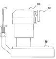
- FIG. 5 is a schematic diagram showing another example of the configuration of a conventional ophthalmologic photographing apparatus.
- Reference numeral 200 indicates an imaging means for imaging the eye to be examined, and reference numeral 201 indicates various kinds of images necessary for imaging. A monitoring means for displaying information is shown.
- FIG. 4 indicates a swinging means for swinging the photographing means 100 about the vertical axis A1
- reference numeral 102 stands for the photographing means 100 (that is, swings in the direction of arrow B2). ) Indicates the means of elevation.
- the monitor means 101 and 201 are attached to the photographing means 100 and 200, when the photographing means 100 and 200 are raised, the monitor means 101 and 201 are also moved upward together. Alternatively, the screen is swung downward, and the angle of the monitor means 101, 201 is changed to make it difficult to see the display.
- An object of the present invention is to provide an ophthalmologic photographing apparatus that can solve the above-described problems.
- the invention according to claim 1 is illustrated in FIG. 1, and in the ophthalmologic photographing apparatus (1) configured to photograph the eye to be examined (E) by the photographing means (7), Swing means supported so as to swing in a substantially horizontal direction (see arrow B1 in FIG. 2) about a substantially vertical first axis (A1) substantially in contact with the anterior eye portion of the eye to be examined (E) 6) and Attached to the swinging means (6) and in a substantially vertical direction (B2) about a substantially horizontal second axis (see symbol A2 in FIG.
- the invention according to claim 2 is characterized in that, in the invention according to claim 1, the monitor means (9) is arranged so as to face substantially the same direction as the viewfinder portion (7a) of the photographing means (7).
- the invention according to claim 3 is the invention according to claim 1 or 2, wherein the swinging means (6) is an arm member supported so as to swing in a substantially horizontal direction (B1),
- the elevating means (8) rolls on the rail member (8a) curved along a virtual arc (C) centered on the second axis (A2), and on the rail member (8a).
- a rolling wheel (not shown) rotatably supported by the photographing means (7), and appropriately rolling the rolling wheel and prohibiting the rolling to make the photographing means (7) the rail member (8a).
- the invention according to claim 4 is the invention according to any one of claims 1 to 3, wherein the monitor means (9) is a substantially horizontal third axis (A3) on the swing means (6). Is attached to the swinging means (6) so as to be able to swing substantially vertically (B3).
- the invention according to claim 5 is the invention according to any one of claims 1 to 4, wherein the monitor means (9) is a touch panel.
- the monitoring means since the monitoring means is not attached to the photographing means, the monitoring means is swung upward or downward even when the photographing means is lifted. And the display will not be difficult to see. Further, since the monitor means is attached to the swinging means, when the photographing means is swung in a substantially horizontal direction, it is swung integrally with the photographing means, so that the examiner can visually recognize it. It will be arranged at an easy position.
- the angle of the monitor means can be adjusted so that the screen is easy to see.
- FIG. 1 is a side view showing an example of the configuration of an ophthalmologic photographing apparatus according to the present invention.
- FIG. 2 is a plan view showing an example of the configuration of the ophthalmologic photographing apparatus according to the present invention.
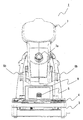
- FIG. 3 is a front view showing an example of the configuration of the ophthalmologic photographing apparatus according to the present invention.
- FIG. 4 is a schematic diagram illustrating an example of a configuration of a conventional ophthalmologic photographing apparatus.
- FIG. 5 is a schematic diagram illustrating another example of the configuration of a conventional ophthalmologic photographing apparatus.
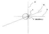
- FIG. 6 is a perspective view for explaining positions of the first shaft and the like.
- An ophthalmologic photographing apparatus is an apparatus for photographing and observing a subject's eye to be examined, As illustrated by reference numeral 1 in FIG. 1, face support means 2A and 2B for supporting the face of a subject and a base 3 on which the face support means 2A and 2B are mounted are provided. Examples of the face support means 2A, 2B include a chin rest (see reference numeral 2A) for placing the subject's chin, a forehead support (see reference numeral 2B) for applying the forehead of the subject, and the like. be able to.
- the pedestal 3 is mounted with a gantry 4 through elevating means (not shown) and slide means (also not shown).
- the gantry 4 is raised and lowered and slid back and forth and horizontally (moved horizontally). It is configured to be able to.
- the operation of the lifting means and the sliding means is performed by the joystick 5.
- the present invention is not limited to this, and may be performed by other operation means.
- the above-described gantry 4 is substantially in contact with the anterior eye portion of the eye E to be examined (strictly speaking, it passes through a pupil position substantially corresponding to the iris position of the anterior eye portion) (FIGS. 1 and 3).
- 6 is supported by the swinging means 6 so as to swing in a substantially horizontal direction (refer to arrow B1 in FIG. 2) centered on an axis indicated by reference numeral A1 and hereinafter referred to as “first axis”.
- the oscillating means 6 supports an imaging means 7 for imaging or observing the eye E to be examined via an elevation means 8.
- This elevating means 8 is a substantially horizontal axis (referred to as A2 in FIGS.
- the photographing means 7 is supported so that the photographing means 7 can be swung (elevated) in a substantially vertical direction (see arrow B2 in FIG. 1) centering on "". That is, since the imaging means 7 is mounted on the gantry 4, it can be moved up and down and / or horizontally moved to a position corresponding to the eye E. Further, since the photographing means 7 is supported by the swinging means 6 and the elevation means 8 as described above, the subject eye E can be photographed not only from the front but also from an oblique direction. Note that an illumination optical system and a photographing optical system are stored in the photographing means 7, but description thereof will be omitted.
- the illustrated swinging means 6 may include an arm member supported so as to swing in a substantially horizontal direction B1 about the first axis A1. Further, as shown in FIG. A rail member 8a curved along a virtual arc C centered on the second axis A2, A rolling wheel (not shown) rotatably supported by the photographing means 7 so as to roll on the rail member 8a; An operation member 8b for appropriately rolling the rolling wheel and prohibiting the rolling to stop the photographing means 7 at a desired position on the rail member 8a; Can be mentioned.
- symbol D in FIG. 6 shows the optical axis (reference
- a monitor means 9 is attached to the swinging means 6 instead of the elevation means 8 and the image taking means 7, and the monitor means 9 is integrated with the image taking means 7 around the first axis A1. Is configured to oscillate. Therefore, this monitoring means 9 When the photographing means 7 is swung in the substantially horizontal direction B1 by the swinging means 6, it swings integrally with the photographing means 7, When the photographing means 7 is lifted and lowered by the raising and lowering means 8, it remains stationary without swinging; It will be.
- Examples of the monitor means 9 include known monitors such as a liquid crystal monitor, and the monitor means 9 may display an image necessary for observation and photographing of the eye E.
- the monitor means 9 is arranged so as to face substantially the same direction as the viewfinder portion 7a of the photographing means 7 (that is, as shown in FIG. 3, it is arranged to face the examiner's direction). good).
- the monitor unit 9 may be a touch panel. In this case, various buttons (for example, buttons for selecting a fixation method) may be displayed on the monitor unit 9. In such a case, various instructions can be given using the monitor means 9.
- the monitor means 9 shown in the figure has a substantially vertical direction B3 centered on a substantially horizontal axis on the swinging means 6 (the axis indicated by reference numeral A3 in FIG. 1 and hereinafter referred to as "third axis"). It is preferable to attach to the swinging means 6 so that it can swing. In such a case, the angle of the monitor means 9 can be adjusted so that the screen is easy to see.
- the monitor means 9 since the monitor means 9 is not attached to the photographing means 7, even when the photographing means 7 is lifted, the monitor means 9 is not swung upward or downward. The display will not be difficult to see. Further, since the monitor means 9 is attached to the swinging means 6, when the photographing means 7 is swung in a substantially horizontal direction B1, it is swung integrally with the photographing means 7, It will be arranged at a position where the examiner can easily recognize.
- the ophthalmologic photographing apparatus includes not only an ophthalmic photographing apparatus for photographing the fundus but also an ophthalmic photographing apparatus for photographing the anterior eye part and an ophthalmic photographing apparatus for photographing other parts. Shall be.
Landscapes
- Life Sciences & Earth Sciences (AREA)
- Health & Medical Sciences (AREA)
- Medical Informatics (AREA)
- Biophysics (AREA)
- Ophthalmology & Optometry (AREA)
- Engineering & Computer Science (AREA)
- Biomedical Technology (AREA)
- Heart & Thoracic Surgery (AREA)
- Physics & Mathematics (AREA)
- Molecular Biology (AREA)
- Surgery (AREA)
- Animal Behavior & Ethology (AREA)
- General Health & Medical Sciences (AREA)
- Public Health (AREA)
- Veterinary Medicine (AREA)
- Eye Examination Apparatus (AREA)
Abstract
【課題】眼科撮影装置において、撮影ユニットを揺動させる場合でもモニターが見やすいようにする。 【解決手段】撮影ユニット7は、被検眼Eを中心として水平方向に揺動できるようにアーム部材6によって支持されており、被検眼Eを中心として上下方向B2に揺動(俯仰)できるようにレール部材8aによって支持されている。モニター手段9は、アーム部材6に取り付けられてて撮影ユニット7には取り付けられていないため、該撮影ユニット7を上下に揺動(俯仰)させた場合でもその角度(画面の角度)は変化せず、モニター手段9は見やすい位置に保持される。一方、撮影ユニット7を水平方向に揺動した場合にはモニター手段9は一緒に揺動するので、撮影ユニット7とモニター手段9とが離れてしまうことが無く、モニター手段9は見やすい位置に保持される。
Description
本発明は、被検眼を撮影手段により撮影するように構成した眼科撮影装置に関する。
従来、被検眼の眼底や前眼部などを撮影する眼科撮影装置としては種々の構成のものが提案されている(例えば、特許文献1及び2参照)。
図4は、従来の眼科撮影装置の構成の一例を示す模式図であり、符号Eは被検眼を示し、符号100は、該被検眼Eを撮影するための撮影手段を示し、符号101は、撮影に必要な種々の情報を表示するモニター手段を示す。また、図5は、従来の眼科撮影装置の構成の他の例を示す模式図であり、符号200は、被検眼を撮影するための撮影手段を示し、符号201は、撮影に必要な種々の情報を表示するモニター手段を示す。
また、このような眼科撮影装置においては被検眼を正面から撮影するだけでなく、撮影手段を揺動させて被検眼を斜めの方向から撮影できるものもあった。図4中の符号102は、前記撮影手段100を鉛直軸A1の周りに揺動させる首振り手段を示し、符号102は、前記撮影手段100を俯仰する(つまり、矢印B2の方向に揺動させる)俯仰手段を示す。
ところで、上記従来の眼科撮影装置においてはモニター手段101,201が撮影手段100,200に取り付けられているため、該撮影手段100,200を俯仰させた場合にはモニター手段101,201も一緒に上方又は下方に揺動されてしまい、該モニター手段101,201の角度が変わって表示が見にくくなってしまうという問題があった。
本発明は、上述の問題を解消することのできる眼科撮影装置を提供することを目的とするものである。
請求項1に係る発明は、図1に例示するものであって、被検眼(E)を撮影手段(7)により撮影するように構成された眼科撮影装置(1)において、
被検眼(E)の前眼部にほぼ接している略鉛直な第1軸(A1)を中心として略水平方向(図2の矢印B1参照)に揺動するように支持された首振り手段(6)と、
該首振り手段(6)に取り付けられると共に、被検眼(E)の前眼部にほぼ接している略水平な第2軸(図2の符号A2参照)を中心として略上下方向(B2)に揺動するように前記撮影手段(7)を支持する俯仰手段(8)と、
前記首振り手段(6)に取り付けられて、前記第1軸(A1)を中心として前記撮影手段(7)と一体的に揺動するように構成されたモニター手段(9)と、を備えたことを特徴とする。
被検眼(E)の前眼部にほぼ接している略鉛直な第1軸(A1)を中心として略水平方向(図2の矢印B1参照)に揺動するように支持された首振り手段(6)と、
該首振り手段(6)に取り付けられると共に、被検眼(E)の前眼部にほぼ接している略水平な第2軸(図2の符号A2参照)を中心として略上下方向(B2)に揺動するように前記撮影手段(7)を支持する俯仰手段(8)と、
前記首振り手段(6)に取り付けられて、前記第1軸(A1)を中心として前記撮影手段(7)と一体的に揺動するように構成されたモニター手段(9)と、を備えたことを特徴とする。
請求項2に係る発明は、請求項1に係る発明において、前記モニター手段(9)は、前記撮影手段(7)のファインダー部(7a)と略同じ方向を向くように配置されたことを特徴とする。
請求項3に係る発明は、請求項1又は2に係る発明において、前記首振り手段(6)は、略水平方向(B1)に揺動するように支持されたアーム部材であり、
前記俯仰手段(8)は、前記第2軸(A2)を中心とした仮想円弧(C)に沿うように湾曲されたレール部材(8a)と、該レール部材(8a)上を転動するように前記撮影手段(7)に回転自在に支持された転動輪(不図示)と、該転動輪を適宜転動させると共に該転動を禁止して前記撮影手段(7)を前記レール部材(8a)上の所望の位置に停止させる操作部材(8b)と、からなることを特徴とする。
前記俯仰手段(8)は、前記第2軸(A2)を中心とした仮想円弧(C)に沿うように湾曲されたレール部材(8a)と、該レール部材(8a)上を転動するように前記撮影手段(7)に回転自在に支持された転動輪(不図示)と、該転動輪を適宜転動させると共に該転動を禁止して前記撮影手段(7)を前記レール部材(8a)上の所望の位置に停止させる操作部材(8b)と、からなることを特徴とする。
請求項4に係る発明は、請求項1乃至3のいずれか1項に記載の発明において、前記モニター手段(9)は、前記首振り手段(6)上における略水平な第3軸(A3)を中心として略上下方向(B3)に揺動できるように前記首振り手段(6)に取り付けられたことを特徴とする。
請求項5に係る発明は、請求項1乃至4のいずれか1項に記載の発明において、前記モニター手段(9)はタッチパネルであることを特徴とする。
なお、括弧内の番号などは、図面における対応する要素を示す便宜的なものであり、従って、本記述は図面上の記載に限定拘束されるものではない。
請求項1乃至3に係る発明によれば、前記モニター手段は、前記撮影手段には取り付けられていないので、該撮影手段を俯仰させた場合でも該モニター手段は上方又は下方に揺動されることはなく、表示が見にくくなってしまうことは無い。また、該モニター手段は前記首振り手段に取り付けられているので、前記撮影手段を略水平方向に揺動させた場合には該撮影手段と一体的に揺動されるので、検者が視認し易い位置に配置されることとなる。
請求項4に係る発明によれば、画面を見やすいようにモニター手段の角度調整をすることができる。
請求項5に係る発明によれば、モニター手段を使って種々の指示を行うことができる。
以下、図1乃至図3に沿って、本発明の実施の形態について説明する。
本発明に係る眼科撮影装置は、被検者の被検眼を撮影及び観察するための装置であって、
図1に符号1で例示するように、被検者の顔を支持する顔支持手段2A,2Bと、該顔支持手段2A,2Bが搭載される基台3と、を備えている。なお、前記顔支持手段2A,2Bとしては、被検者の顎を載せるための顎台(符号2A参照)や、被検者の額を当てるための額当て部(符号2B参照)等を挙げることができる。
図1に符号1で例示するように、被検者の顔を支持する顔支持手段2A,2Bと、該顔支持手段2A,2Bが搭載される基台3と、を備えている。なお、前記顔支持手段2A,2Bとしては、被検者の顎を載せるための顎台(符号2A参照)や、被検者の額を当てるための額当て部(符号2B参照)等を挙げることができる。
また、この基台3には、昇降手段(不図示)及びスライド手段(同じく不図示)を介して架台4が搭載されており、該架台4を昇降させたり前後左右にスライド(水平移動)させたりできるように構成されている。図示の装置においては、これらの昇降手段及びスライド手段の操作をジョイスティック5により行うようになっているが、もちろんこれに限られるものではなく、他の操作手段によって行うようにしても良い。
さらに、上述の架台4には、被検眼Eの前眼部にほぼ接している(厳密にいうと前眼部の虹彩位置にほぼ相当する瞳位置を通る)略鉛直な軸(図1及び図6に符号A1で示す軸であって、以下、“第1軸”とする)を中心として略水平方向(図2の矢印B1参照)に揺動するように首振り手段6が支持されており、該首振り手段6には、被検眼Eを撮影又は観察するための撮影手段7が俯仰手段8を介して支持されている。この俯仰手段8は、被検眼Eの前眼部にほぼ接している(瞳位置を通る)略水平な軸(図2及び図6に符号A2で示す軸であって、以下、“第2軸”とする)を中心として前記撮影手段7を略上下方向(図1の矢印B2参照)に揺動(俯仰)できるように該撮影手段7を支持している。つまり、該撮影手段7は、前記架台4上に搭載されているので被検眼Eに応じた位置に昇降及び/又は水平移動させることができる。また、前記撮影手段7は上述のように首振り手段6及び俯仰手段8によって支持されているため、被検眼Eを正面から撮影するだけでなく斜めの方向からも撮影できる。なお、前記撮影手段7の内部には照明光学系や撮影光学系が格納されているが、それらについての説明は省略する。また、図示の首振り手段6としては、前記第1軸A1を中心として略水平方向B1に揺動するように支持されたアーム部材を挙げることができる。さらに、図示の俯仰手段8としては、
・ 前記第2軸A2を中心とした仮想円弧Cに沿うように湾曲されたレール部材8aと、
・ 該レール部材8a上を転動するように前記撮影手段7に回転自在に支持された転動輪(不図示)と、
・ 該転動輪を適宜転動させると共に該転動を禁止して前記撮影手段7を前記レール部材8a上の所望の位置に停止させる操作部材8bと、
により構成したものを挙げることができる。なお、図6中の符号Dは、被検眼Eの光軸(基準光軸)を示す。
・ 前記第2軸A2を中心とした仮想円弧Cに沿うように湾曲されたレール部材8aと、
・ 該レール部材8a上を転動するように前記撮影手段7に回転自在に支持された転動輪(不図示)と、
・ 該転動輪を適宜転動させると共に該転動を禁止して前記撮影手段7を前記レール部材8a上の所望の位置に停止させる操作部材8bと、
により構成したものを挙げることができる。なお、図6中の符号Dは、被検眼Eの光軸(基準光軸)を示す。
一方、前記俯仰手段8や前記撮影手段7にではなく前記首振り手段6にはモニター手段9が取り付けられていて、該モニター手段9は、前記第1軸A1を中心として前記撮影手段7と一体的に揺動するように構成されている。したがって、このモニター手段9は、
・ 前記撮影手段7が該首振り手段6によって略水平方向B1に揺動される場合には該撮影手段7と共に一体的に揺動し、
・ 前記撮影手段7が前記俯仰手段8によって俯仰される場合には、揺動されずに静止する、
こととなる。このモニター手段9としては、液晶モニター等の公知のモニターを挙げることができ、該モニター手段9には、被検眼Eの観察や撮影に必要な画像を表示すれば良く、例えば、
・ 被検眼Eに位置合わせをする際の画像や、
・ ピント合わせをする際の画像や、
・ 赤外光を使って撮影している被検眼の画像や、
・ 撮影情報
等を表示すれば良い。また、このモニター手段9は、前記撮影手段7のファインダー部7aと略同じ方向を向くように配置しておくと良い(つまり、図3に示すように、検者の方向を向くように配置すると良い)。さらに、該モニター手段9をタッチパネルとしても良く、その場合には、種々のボタン(例えば、固視方法の選択のためのボタン)を該モニター手段9に表示するようにすると良い。そのようにした場合には、モニター手段9を使って種々の指示を行うことができる。なお、図示のモニター手段9は、前記首振り手段6上における略水平な軸(図1に符号A3で示す軸であって、以下、“第3軸”とする)を中心として略上下方向B3に揺動できるように該首振り手段6に取り付けておくと良い。そのようにした場合には、画面を見やすいようにモニター手段9の角度調整をすることができる。
・ 前記撮影手段7が該首振り手段6によって略水平方向B1に揺動される場合には該撮影手段7と共に一体的に揺動し、
・ 前記撮影手段7が前記俯仰手段8によって俯仰される場合には、揺動されずに静止する、
こととなる。このモニター手段9としては、液晶モニター等の公知のモニターを挙げることができ、該モニター手段9には、被検眼Eの観察や撮影に必要な画像を表示すれば良く、例えば、
・ 被検眼Eに位置合わせをする際の画像や、
・ ピント合わせをする際の画像や、
・ 赤外光を使って撮影している被検眼の画像や、
・ 撮影情報
等を表示すれば良い。また、このモニター手段9は、前記撮影手段7のファインダー部7aと略同じ方向を向くように配置しておくと良い(つまり、図3に示すように、検者の方向を向くように配置すると良い)。さらに、該モニター手段9をタッチパネルとしても良く、その場合には、種々のボタン(例えば、固視方法の選択のためのボタン)を該モニター手段9に表示するようにすると良い。そのようにした場合には、モニター手段9を使って種々の指示を行うことができる。なお、図示のモニター手段9は、前記首振り手段6上における略水平な軸(図1に符号A3で示す軸であって、以下、“第3軸”とする)を中心として略上下方向B3に揺動できるように該首振り手段6に取り付けておくと良い。そのようにした場合には、画面を見やすいようにモニター手段9の角度調整をすることができる。
本発明によれば、前記モニター手段9は、前記撮影手段7には取り付けられていないので、該撮影手段7を俯仰させた場合でも該モニター手段9は上方又は下方に揺動されることはなく、表示が見にくくなってしまうことは無い。また、該モニター手段9は前記首振り手段6に取り付けられているので、前記撮影手段7を略水平方向B1に揺動させた場合には該撮影手段7と一体的に揺動されるので、検者が視認し易い位置に配置されることとなる。
なお、本発明に係る眼科撮影装置は、眼底を撮影するための眼科撮影装置のみならず、前眼部を撮影するための眼科撮影装置や、その他の部分を撮影するための眼科撮影装置を含むものとする。
1 眼科撮影装置
6 首振り手段
7 撮影手段
7a ファインダー部
8 俯仰手段
8a レール部材
8b 操作部材
9 モニター手段
A1 第1軸
A2 第2軸
A3 第3軸
B1 略水平方向
B2 略上下方向
E 被検眼(E)
P 被検眼瞳位置(P)
6 首振り手段
7 撮影手段
7a ファインダー部
8 俯仰手段
8a レール部材
8b 操作部材
9 モニター手段
A1 第1軸
A2 第2軸
A3 第3軸
B1 略水平方向
B2 略上下方向
E 被検眼(E)
P 被検眼瞳位置(P)
Claims (5)
- 被検眼を撮影手段により撮影するように構成された眼科撮影装置において、
被検眼の前眼部にほぼ接している略鉛直な第1軸を中心として略水平方向に揺動するように支持された首振り手段と、
該首振り手段に取り付けられると共に、被検眼の前眼部にほぼ接している略水平な第2軸を中心として略上下方向に揺動するように前記撮影手段を支持する俯仰手段と、
前記首振り手段に取り付けられて、前記第1軸を中心として前記撮影手段と一体的に揺動するように構成されたモニター手段と、
を備えたことを特徴とする眼科撮影装置。 - 前記モニター手段は、前記撮影手段のファインダー部と略同じ方向を向くように配置された、
ことを特徴とする請求項1に記載の眼科撮影装置。 - 前記首振り手段は、略水平方向に揺動するように支持されたアーム部材であり、
前記俯仰手段は、前記第2軸を中心とした仮想円弧に沿うように湾曲されたレール部材と、該レール部材上を転動するように前記撮影手段に回転自在に支持された転動輪と、該転動輪を適宜転動させると共に該転動を禁止して前記撮影手段を前記レール部材上の所望の位置に停止させる操作部材と、からなる、
ことを特徴とする請求項1又は2に記載の眼科撮影装置。 - 前記モニター手段は、前記首振り手段上における略水平な第3軸を中心として略上下方向に揺動できるように前記首振り手段に取り付けられた、
ことを特徴とする請求項1乃至3のいずれか1項に記載の眼科撮影装置。 - 前記モニター手段はタッチパネルである、
ことを特徴とする請求項1乃至4のいずれか1項に記載の眼科撮影装置。
Applications Claiming Priority (2)
| Application Number | Priority Date | Filing Date | Title |
|---|---|---|---|
| JP2010188109A JP5667394B2 (ja) | 2010-08-25 | 2010-08-25 | 眼科撮影装置 |
| JP2010-188109 | 2010-08-25 |
Publications (1)
| Publication Number | Publication Date |
|---|---|
| WO2012026314A1 true WO2012026314A1 (ja) | 2012-03-01 |
Family
ID=45723319
Family Applications (1)
| Application Number | Title | Priority Date | Filing Date |
|---|---|---|---|
| PCT/JP2011/068050 Ceased WO2012026314A1 (ja) | 2010-08-25 | 2011-08-08 | 眼科撮影装置 |
Country Status (2)
| Country | Link |
|---|---|
| JP (1) | JP5667394B2 (ja) |
| WO (1) | WO2012026314A1 (ja) |
Families Citing this family (2)
| Publication number | Priority date | Publication date | Assignee | Title |
|---|---|---|---|---|
| JP6278509B2 (ja) | 2014-01-28 | 2018-02-14 | キヤノン株式会社 | 眼科装置 |
| JP7524014B2 (ja) | 2020-09-25 | 2024-07-29 | 株式会社トプコン | 眼科装置 |
Citations (4)
| Publication number | Priority date | Publication date | Assignee | Title |
|---|---|---|---|---|
| JP2001046341A (ja) * | 1999-08-12 | 2001-02-20 | Ryusyo Industrial Co Ltd | 眼科測定装置 |
| JP2006026097A (ja) * | 2004-07-15 | 2006-02-02 | Topcon Corp | 眼底カメラ |
| JP2006026096A (ja) * | 2004-07-15 | 2006-02-02 | Topcon Corp | 眼科装置 |
| JP2008272259A (ja) * | 2007-04-27 | 2008-11-13 | Nidek Co Ltd | 眼科装置 |
-
2010
- 2010-08-25 JP JP2010188109A patent/JP5667394B2/ja not_active Expired - Fee Related
-
2011
- 2011-08-08 WO PCT/JP2011/068050 patent/WO2012026314A1/ja not_active Ceased
Patent Citations (4)
| Publication number | Priority date | Publication date | Assignee | Title |
|---|---|---|---|---|
| JP2001046341A (ja) * | 1999-08-12 | 2001-02-20 | Ryusyo Industrial Co Ltd | 眼科測定装置 |
| JP2006026097A (ja) * | 2004-07-15 | 2006-02-02 | Topcon Corp | 眼底カメラ |
| JP2006026096A (ja) * | 2004-07-15 | 2006-02-02 | Topcon Corp | 眼科装置 |
| JP2008272259A (ja) * | 2007-04-27 | 2008-11-13 | Nidek Co Ltd | 眼科装置 |
Also Published As
| Publication number | Publication date |
|---|---|
| JP5667394B2 (ja) | 2015-02-12 |
| JP2012045083A (ja) | 2012-03-08 |
Similar Documents
| Publication | Publication Date | Title |
|---|---|---|
| US12446774B2 (en) | Apparatus, systems, and methods for objectively assessing accommodation in an eye | |
| JP6278509B2 (ja) | 眼科装置 | |
| JP7594922B2 (ja) | 眼科装置 | |
| US11992267B2 (en) | Ophthalmologic apparatus and ophthalmologic system | |
| JP2009254725A (ja) | 超音波診断装置 | |
| JP2012148030A (ja) | 検眼装置 | |
| JP5667394B2 (ja) | 眼科撮影装置 | |
| JP7227795B2 (ja) | 眼科装置 | |
| JP2968513B1 (ja) | モニター付きスタンド装置 | |
| JP2020141828A (ja) | 眼科装置 | |
| JP5717227B1 (ja) | 検眼装置 | |
| JP4587741B2 (ja) | 眼科装置 | |
| JP2011120610A (ja) | 視野計及びこれを備えるスリットランプ | |
| JP7178211B2 (ja) | 検眼装置 | |
| JP5717228B1 (ja) | 検眼装置 | |
| JP7728120B2 (ja) | 眼科装置 | |
| JP2012148031A (ja) | 検眼装置 | |
| JP5749502B2 (ja) | 検眼装置 | |
| JP7843168B2 (ja) | 眼科システム | |
| JP2006026097A (ja) | 眼底カメラ | |
| JP2022053907A (ja) | 眼科装置 | |
| JP2025047636A (ja) | 眼科装置、顎受けアタッチメント | |
| CN120000151A (zh) | 弱视旁中心注视可视化纠旁装置 | |
| CN120713456A (zh) | 眼科装置 | |
| JPH03254724A (ja) | 眼科装置 |
Legal Events
| Date | Code | Title | Description |
|---|---|---|---|
| 121 | Ep: the epo has been informed by wipo that ep was designated in this application |
Ref document number: 11819778 Country of ref document: EP Kind code of ref document: A1 |
|
| NENP | Non-entry into the national phase |
Ref country code: DE |
|
| 122 | Ep: pct application non-entry in european phase |
Ref document number: 11819778 Country of ref document: EP Kind code of ref document: A1 |