WO2012023538A1 - 通信装置、通信システム、通信方法、および記録媒体 - Google Patents
通信装置、通信システム、通信方法、および記録媒体 Download PDFInfo
- Publication number
- WO2012023538A1 WO2012023538A1 PCT/JP2011/068518 JP2011068518W WO2012023538A1 WO 2012023538 A1 WO2012023538 A1 WO 2012023538A1 JP 2011068518 W JP2011068518 W JP 2011068518W WO 2012023538 A1 WO2012023538 A1 WO 2012023538A1
- Authority
- WO
- WIPO (PCT)
- Prior art keywords
- communication
- network
- frame
- unit
- information
- Prior art date
Links
- 230000006854 communication Effects 0.000 title claims abstract description 218
- 238000004891 communication Methods 0.000 title claims abstract description 204
- 238000000034 method Methods 0.000 title claims description 43
- 238000005259 measurement Methods 0.000 claims abstract description 98
- 238000012545 processing Methods 0.000 claims abstract description 81
- 230000005540 biological transmission Effects 0.000 claims description 33
- 238000004364 calculation method Methods 0.000 claims description 19
- 238000004148 unit process Methods 0.000 abstract 1
- 238000010586 diagram Methods 0.000 description 12
- 238000012546 transfer Methods 0.000 description 11
- 238000012544 monitoring process Methods 0.000 description 7
- 230000006870 function Effects 0.000 description 5
- 239000004065 semiconductor Substances 0.000 description 5
- RTZKZFJDLAIYFH-UHFFFAOYSA-N Diethyl ether Chemical compound CCOCC RTZKZFJDLAIYFH-UHFFFAOYSA-N 0.000 description 4
- 238000005538 encapsulation Methods 0.000 description 3
- 238000011084 recovery Methods 0.000 description 2
- 239000000969 carrier Substances 0.000 description 1
- 238000001514 detection method Methods 0.000 description 1
- 238000005516 engineering process Methods 0.000 description 1
- 238000012423 maintenance Methods 0.000 description 1
- 238000005457 optimization Methods 0.000 description 1
Images


Classifications
-
- H—ELECTRICITY
- H04—ELECTRIC COMMUNICATION TECHNIQUE
- H04L—TRANSMISSION OF DIGITAL INFORMATION, e.g. TELEGRAPHIC COMMUNICATION
- H04L43/00—Arrangements for monitoring or testing data switching networks
- H04L43/50—Testing arrangements
-
- H—ELECTRICITY
- H04—ELECTRIC COMMUNICATION TECHNIQUE
- H04L—TRANSMISSION OF DIGITAL INFORMATION, e.g. TELEGRAPHIC COMMUNICATION
- H04L45/00—Routing or path finding of packets in data switching networks
- H04L45/54—Organization of routing tables
-
- H—ELECTRICITY
- H04—ELECTRIC COMMUNICATION TECHNIQUE
- H04L—TRANSMISSION OF DIGITAL INFORMATION, e.g. TELEGRAPHIC COMMUNICATION
- H04L43/00—Arrangements for monitoring or testing data switching networks
- H04L43/02—Capturing of monitoring data
- H04L43/026—Capturing of monitoring data using flow identification
-
- H—ELECTRICITY
- H04—ELECTRIC COMMUNICATION TECHNIQUE
- H04L—TRANSMISSION OF DIGITAL INFORMATION, e.g. TELEGRAPHIC COMMUNICATION
- H04L43/00—Arrangements for monitoring or testing data switching networks
- H04L43/08—Monitoring or testing based on specific metrics, e.g. QoS, energy consumption or environmental parameters
-
- H—ELECTRICITY
- H04—ELECTRIC COMMUNICATION TECHNIQUE
- H04L—TRANSMISSION OF DIGITAL INFORMATION, e.g. TELEGRAPHIC COMMUNICATION
- H04L43/00—Arrangements for monitoring or testing data switching networks
- H04L43/20—Arrangements for monitoring or testing data switching networks the monitoring system or the monitored elements being virtualised, abstracted or software-defined entities, e.g. SDN or NFV
-
- H—ELECTRICITY
- H04—ELECTRIC COMMUNICATION TECHNIQUE
- H04L—TRANSMISSION OF DIGITAL INFORMATION, e.g. TELEGRAPHIC COMMUNICATION
- H04L45/00—Routing or path finding of packets in data switching networks
- H04L45/70—Routing based on monitoring results
-
- H—ELECTRICITY
- H04—ELECTRIC COMMUNICATION TECHNIQUE
- H04L—TRANSMISSION OF DIGITAL INFORMATION, e.g. TELEGRAPHIC COMMUNICATION
- H04L41/00—Arrangements for maintenance, administration or management of data switching networks, e.g. of packet switching networks
- H04L41/06—Management of faults, events, alarms or notifications
- H04L41/0654—Management of faults, events, alarms or notifications using network fault recovery
- H04L41/0659—Management of faults, events, alarms or notifications using network fault recovery by isolating or reconfiguring faulty entities
-
- H—ELECTRICITY
- H04—ELECTRIC COMMUNICATION TECHNIQUE
- H04L—TRANSMISSION OF DIGITAL INFORMATION, e.g. TELEGRAPHIC COMMUNICATION
- H04L41/00—Arrangements for maintenance, administration or management of data switching networks, e.g. of packet switching networks
- H04L41/40—Arrangements for maintenance, administration or management of data switching networks, e.g. of packet switching networks using virtualisation of network functions or resources, e.g. SDN or NFV entities
-
- H—ELECTRICITY
- H04—ELECTRIC COMMUNICATION TECHNIQUE
- H04L—TRANSMISSION OF DIGITAL INFORMATION, e.g. TELEGRAPHIC COMMUNICATION
- H04L45/00—Routing or path finding of packets in data switching networks
- H04L45/02—Topology update or discovery
Definitions
- the present invention relates to a communication device, a communication system, a communication method, and a recording medium that measure the state of a communication path.
- OpenFlow regards communication as an end-to-end flow, and performs path control, failure recovery, load distribution, and optimization in units of flows.
- An OpenFlow Switch (OFS) functioning as a forwarding node includes a secure channel (Secure Channel) for communication with an OpenFlow Controller (OFC), and operates according to a flow table instructed to be added or rewritten as appropriate from the OFC.
- a flow table instructed to be added or rewritten as appropriate from the OFC.
- a set of a rule that collates with the packet header, an action that defines the processing content, and flow statistical information is defined.
- OFS searches the flow table for an entry having a rule (FlowKey) that matches the header information of the received packet. If an entry that matches the received packet is found as a result of the search, the OFS performs the processing content described in the action field of the entry on the received packet. On the other hand, if no entry matching the received packet is found as a result of the search, the OFS transfers the received packet or the header information of the received packet to the OFC via the secure channel. By this transfer, a request for determining a packet path based on the transmission source / destination of the received packet is requested, and a flow entry for realizing this is received, and the flow table is updated.
- FlowKey a rule
- Non-Patent Document 1 when a path failure or congestion occurs and a path needs to be switched, generally, the OFC performs topology reconstruction and path calculation.
- the flow table of each OFS is set.
- An object of the present invention is to provide a communication device, a communication system, a communication method, and a communication program that can solve the above-described problems.
- a communication device belonging to a network includes an adding unit that adds information for communication status measurement to a received frame when the communication device is an ingress edge node of the network, and the communication device A measurement unit that measures the communication status based on the information for communication status measurement and a measurement result that notifies the control device that controls the network of the measurement result of the communication status when it is an egress edge node of the network
- the notification unit the received frame identification information
- the processing rule storage unit that stores the processing rule that associates the frame identification information with the processing for the frame, and processes the received frame according to the processing rule And a processing unit.
- the communication system includes the communication device described above, a route calculation unit that calculates the route of the received frame from the measurement result received from the communication device, and a route that stores the calculated route.
- a control device includes a storage unit and a route transmission unit that sets a frame processing rule for a communication device on the route based on the route stored in the route storage unit.
- the communication method includes a step of adding information for measuring a communication state to a received frame when the communication device belonging to the network is an ingress edge node of the network; When the network is an egress edge node of the network, the step of measuring the communication status based on the information for communication status measurement, the step of notifying the measurement result of the communication status to the control device that controls the network, and reception A step of referring to the frame identification information and processing the received frame in accordance with a processing rule that associates the frame identification information with the processing for the frame.
- a non-transitory storage medium storing a program that, when executed, causes a communication device belonging to a network to execute a communication process.
- the communication process includes a step of adding information for measuring a communication state to a received frame when the communication device is an ingress edge node of the network, and when the communication device is an egress edge node of the network.
- the step of measuring the communication status based on the information for measuring the communication status, the step of notifying the control device that controls the network of the measurement result of the communication status, and the identification information of the received frame, Processing the received frame according to a processing rule that associates the identification information with the processing for the frame.
- FIG. 1 is a block diagram showing a configuration of a system according to the first embodiment.
- the system shown in FIG. 1 includes a network 150, a network 160, and a network 170.
- the network 150 includes a switch 100, a switch 120, a switch 130, a switch 140, and a control server 110.
- the operation in the network 150 will be mainly described.
- the arrows in FIG. 1 indicate packet paths (switch 100-switch 120-switch 130-switch 140) described in the present embodiment.
- the control server 110 and each switch are connected as shown by dotted lines. This connection may be a dedicated line different from the network connecting the switches, or the same network.
- the switch 100 and the switch 140 connected to the other network 160 and the network 170 operate as an ingress edge node and an egress edge node, respectively.
- Non-Patent Document 1 when the OpenFlow described in Non-Patent Document 1 is applied to the network 150 in FIG. 1, the switches 100 to 140 correspond to OFS, and the control server 110 corresponds to OFC.
- OpenFlow will be described as an example, but the scope of application of this embodiment is not limited to OpenFlow. Similar to OpenFlow, any technique that centrally manages a network can be applied.
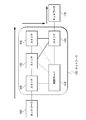
- FIG. 2 is a block diagram showing the configuration of the switch 100 and the control server 110 according to the first embodiment.
- FIG. 2 shows only the configuration of the switch 100, but the switches 120, 130, and 140 in FIG.
- the switch 100 includes a measurement unit 101, a measurement result notification unit 102, an addition unit 103, a processing unit 104, a processing storage unit 105, a control server interface unit 106, an OpenFlow network interface unit 107, and a network interface unit 108.
- the measuring unit 101 measures the communication status from the sequence number included in the received frame, the transmission time of the frame, and the like. More specifically, the communication status is measured by calculating a frame loss rate, an average delay time, and an average reception rate. This measurement is performed when the switch is located at the egress edge node in the network. In the case of the network 150 in FIG. 1, the above measurement is performed in the switch 140.
- the measurement result notification unit 102 transmits the measurement result to the control server 110 via the control server interface unit 106 when the measurement unit 101 measures the communication status.
- the adding unit 103 adds information necessary for transfer in the network 150 in addition to the above-described information for measuring the communication status (sequence number, frame transmission time). In the present embodiment, this is achieved by using a method called PBB (Provider Backbone Bridge).
- PBB Provide Backbone Bridge
- the application example of the present embodiment is not limited to the PBB, and a technique for encapsulating received data (EoE: Ethernet (registered trademark) Over Ethernet) is also applicable. It is also possible to simply add the above-mentioned information for measuring the communication status and information necessary for transfer to the received frame.
- PBB is a technology for backbone networks to bundle networks using PB (Provider Bridge), which is a communication method for carriers, and is being standardized by IEEE (The Institute of Electrical Engineers). It is.
- PB Provider Bridge
- an edge node is provided at the boundary between the PBB network and the PB network.
- a frame received from the PB network is converted into a MAC (Media Access Control) -in-MAC frame, and communication using the MAC-in-MAC frame is performed in the PBB network.
- MAC Media Access Control
- the network 160 and the network 170 in FIG. 1 are applied to the PB network and the network 150 is applied to the PBB network.
- the network 160 and the network 170 are not limited to the PB network, and any network can be applied.
- FIG. 5 shows a frame format used in this embodiment.
- the frame in FIG. 5 is a received frame including dst MAC (destination MAC address), src MAC (source MAC address), Type (Ether Type), PDU (Protocol Data Unit), and FCS (Frame Check Sequence: frame error detection).
- dst MAC destination MAC address
- src MAC source MAC address
- Type Ether Type
- PDU Protocol Data Unit
- FCS Flash Sequence: frame error detection
- the PBB header includes Backbone dst MAC (backbone destination MAC address: “destination B-MAC address”), Backbone src MAC (backbone source MAC address: “source B-MAC address”), B-TAG (Backbone VLAN). Tag) and I-TAG (Service Instance Tag).
- the destination B-MAC address indicates the destination MAC address of the frame used in the network 150
- the source B-MAC address indicates the source MAC address of the frame in the network 150.
- the B-TAG stores a path identifier used in the network 150, B-VID (B-VLAN ID: Backbone-Virtual Local Area Network Identifier).
- I-TAG used in this embodiment will be described.
- I-TAG includes I-TAG TPID (I-TAG Protocol Identifier: I-TAG protocol ID), I-PCP (I-TAG Priority Code Point: I-TAG priority code point), I -Includes DEI (I-TAG Drop Elligible Indication: I-TAG priority discard identification), reservation, and I-SID (Service Instance ID).
- I-TAG TPID I-TAG Protocol Identifier: I-TAG protocol ID
- I-PCP I-TAG Priority Code Point: I-TAG priority code point
- I -Includes DEI I-TAG Drop Elligible Indication: I-TAG priority discard identification
- reservation and I-SID (Service Instance ID).
- a Flow ID is an identifier for each flow in OpenFlow, which is added at the ingress edge node of the network 150 (switch 100 in FIG. 1). This Flow ID is managed by the control server 110.
- the sequence number is added at the ingress edge node of the network 150.
- the sequence number is a numerical value that is incremented by 1 each time a frame (same flow frame) that passes through the same route is transmitted.
- the egress edge node (switch 140 in FIG. 1) of the network 150 measures the reception rate and frame loss in the path by monitoring this value.
- the transmission time information is added at the entrance edge node of the network 150.
- the transmission time information is acquired from an RTC (Real Time Clock: not shown in the figure) that measures time in the apparatus.
- the egress edge node measures the delay time in the route by comparing the transmission time information added to the frame with the current time information acquired from the RTC in the own device.
- sequence number can be selected and add either the sequence number or the transmission time information according to the determination of which information is measured from the frame loss rate, the average delay time, and the average reception rate.
- the sequence number can be measured, and when the average delay time or the average reception rate is measured, transmission time information can be added, respectively.
- the processing unit 104 processes the received frame according to the processing rule (entry) corresponding to the received frame stored in the flow table 105-1 in the processing storage unit 105.
- This processing rule corresponds to a flow table entry in OpenFlow. Details of the flow table 105-1 will be described later.
- processing rule corresponding to the received frame in the flow table 105-1 it is searched whether there is a processing rule corresponding to the received frame in the flow table 105-1. If there is a processing rule corresponding to the flow table 105-1, the described processing is performed. This process corresponds to “Action” in OpenFlow.
- the processing in this embodiment is typically assumed to be transferred to the next switch on the transfer path of the received frame, but is not limited to this. Examples of processing other than transfer include unicast, multicast, discard control, load distribution control, failure recovery control, virtual port / tunnel transfer control, and encryption.
- control server 110 is inquired about the processing of the received frame via the control server interface unit 106. This operation corresponds to the “Packet-in” operation in OpenFlow.
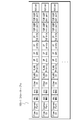
- FIG. 3 is a block diagram showing details of the processing storage unit 105.
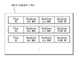
- the processing storage unit 105 stores a flow table 105-1 shown in FIG. 6 and a PBB table 105-2 shown in FIG.
- the flow table 105-1 stores an entry in which a search key for each flow is associated with a process (Action).
- the Flow ID indicates a flow identifier as described above.
- Ingress Port indicates the input port of the frame.
- dst MAC indicates the destination MAC address of the frame.
- src MAC indicates the source MAC address of the frame.
- the Ether ID indicates the Ether Type of the frame.
- the VLAN ID indicates the VLAN ID of the frame.
- VLAN Priority indicates the priority (priority) of the frame.
- IP src indicates a frame source IP (Internet Protocol) address.
- IP dst indicates the destination IP address of the frame.
- IP Proto indicates the IP protocol type of the frame.
- IP ToS bits indicates the ToS (Type of Service) of the IP of the frame.
- TCP / UDP src port indicates a transmission source port number of TCP / UDP (Transmission Control Protocol / User Datagram Protocol) of a frame.
- TCP / UDP dst port indicates the TCP / UDP destination port number of the frame.
- Action indicates the processing content for the corresponding frame.
- Examples of flow search keys include selection of a source MAC address, a destination MAC address, a VLAN-ID (Virtual Local Area Network Identifier), and the like.
- the flow table 105-1 corresponds to a flow table in OpenFlow.
- the PBB table 105-2 stores a Flow ID, a destination B-MAC address, a source B-MAC address, and a B-VID.
- the control server interface unit 106 is an interface for communication between the switch 100 and the control server 110. In OpenFlow, communication is performed via Secure Channel.
- the OpenFlow network interface unit 107 is a communication interface with a node (switch 120 in FIG. 1) on a network (network 150 in FIG. 1) to which OpenFlow is applied.
- the network interface unit 108 is a communication interface with a network other than the OpenFlow network (the network 160 and the network 170 in FIG. 1).
- the measurement unit 101, the measurement result notification unit 102, the addition unit 103, the processing unit 104, the control server interface unit 106, the OpenFlow network interface unit 107, and the network interface unit 108 may be implemented as hardware, software, May be implemented as a combination of arithmetic devices that execute the above.
- the installed software may be installed in the switch 100 using the non-transitory recording medium 100a that stores the software.
- the processing storage unit 105 may be mounted as an arbitrary storage device such as a semiconductor memory.
- the control server 110 includes a route calculation unit 111, a route transmission unit 112, and a control information storage unit 113.
- the route calculation unit 111 refers to the control information storage unit 113 and calculates a flow route by a predetermined algorithm according to the received information. More specifically, the route calculation unit 111 first receives a communication state measurement result or a Packet-in message from the switch 100. Next, referring to the topology information of the network 150 stored in the control information storage unit 113, an appropriate flow path is calculated by a predetermined algorithm. Any algorithm may be used for route calculation.
- the route transmission unit 112 notifies the processing storage unit 105 of each switch on the route of the processing rule corresponding to the route calculated by the route calculation unit 111 via the control server interface unit 106.
- the switch 100 is notified of information necessary for encapsulation of the PBB header (destination B-MAC address, source B-MAC address, B-VID, etc.). This operation corresponds to “Flow_mod” in OpenFlow.
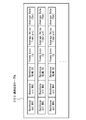
- FIG. 4 is a block diagram showing details of the control information storage unit 113.
- the control information storage unit 113 includes a topology table 113-1, a communication status table 113-2, and a MAC search table 113-3.
- the topology table 113-1 stores the topology information of the network 150 controlled by the control server 110.
- the communication status table stores the communication status for each communication path (flow). Note that the topology table 113-1 may have any data structure, and thus a detailed description thereof is omitted.
- FIG. 8 shows details of the communication status table 113-2.
- the communication status table 113-2 stores Frame Loss, Average Delay Time, and Average Rate in addition to the destination B-MAC address, source B-MAC address, and B-VID.
- Frame Loss indicates a frame loss rate in the corresponding route, and its unit is%.
- Average Delay Time indicates the average delay time of the frame in the corresponding route, and its unit is ⁇ s (micro seconds).
- Average Rate indicates the average reception rate of frames in the corresponding route, and its unit is fps (frame per second).
- FIG. 9 shows the details of the MAC search table 113-3.
- the MAC search table 113-3 is a table that stores a MAC included in a received frame from outside the network 150 and a B-MAC address for PBB used in the network 150 in association with each other.
- the MAC search table 113-3 is created when the network 150 is constructed.
- the above-described route calculation unit 111 and route transmission unit 112 may be implemented as hardware, or may be implemented as a combination of software and an arithmetic device that executes the software.
- the implemented software may be installed in the control server 110 using a non-transitory recording medium 110a that stores the software.
- the control information storage unit 113 may be implemented as an arbitrary storage device such as a hard disk (disc) drive or a semiconductor memory.
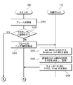
- FIGS. 10 and 11 are sequence charts showing operations of the switch 100 and the control server 110 which are ingress edge nodes.
- FIG. 12 is a sequence chart showing operations of the switch 120, the switch 130, and the control server 110.
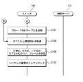
- FIG. 13 is a sequence chart showing the operations of the switch 140 and the control server 110 which are egress edge nodes.
- the switch 100 receives a frame from a node (not shown in the figure) in the network 160 (FIG. 10: step S101).
- the format of the received frame (hereinafter referred to as “received frame”) corresponds to the “original data” portion of the frame format shown in FIG.
- the processing unit 104 searches the flow table 105-1 for an entry corresponding to the received frame using the information stored in the header of the received frame as a key (FIG. 10: step S102). If there is a corresponding entry as a result of the search, step S108 in FIG. If there is no corresponding entry as a result of the search, the header information of the received frame is transferred to the control server 110 (FIG. 10: Step S103).
- control server 110 searches for the corresponding destination B-MAC address using the destination MAC address (dst MAC) stored in the header information of the received frame as a key (FIG. 10: step S104).
- the route calculation unit 111 determines a route by a predetermined algorithm based on the header information of the received frame and the communication status of the related route.
- the determined route is stored in the communication status table 113-2 (FIG. 10: Step S105).
- the route transmission unit 112 notifies the processing rule corresponding to the determined route to the flow table 105-1 of each switch on the route. At the same time, the source B-MAC address, destination B-MAC address, B-VID, and Flow ID of the determined route are notified to the PBB table 105-2 (FIG. 10: step S106).
- step S107 the switch 100 updates the flow table 105-1 and the PBB table 105-2 based on the information notified in step S106 (FIG. 11: step S107).
- the adding unit 103 acquires the current time from the RTC (FIG. 11: step S108), performs B-MAC, B-TAG, and I-TAG encapsulation, and transmits the frame. (FIG. 11: Step S109).
- sequence number is incremented and stored in the switch 100.
- the switch 120 receives a frame from the switch 100 (FIG. 12: step S111). Subsequently, the processing unit 104 searches the flow table 105-1 (FIG. 12: Step S112). If there is a corresponding entry, the received frame is processed according to the corresponding entry (FIG. 12: step S113). In the case of the present embodiment, a process of transferring the received frame to the next switch (switch 130) on the transfer path is given. If there is no corresponding entry, an inquiry is made to the control server 110. In this case, since it is assumed that the corresponding entry has already been set, description thereof will be omitted.
- the switch 140 receives a frame from the switch 130 (FIG. 13: step S121).
- the measurement unit 101 compares the sequence number stored in the received frame with the sequence number history stored in the switch 140, and stores the value of (difference-1) (FIG. 13: step S122).
- the measuring unit 101 compares the transmission time information stored in the received frame with the current time information acquired from the RTC, and stores the difference (FIG. 13: step S123).
- the measurement unit 101 compares the stored time information at the time of the previous frame reception with the current time information acquired from the RTC, and stores the difference (FIG. 13: step S124).
- the processing unit 104 decapsulates the PBB header of the received frame and transfers it to the corresponding node of the network 170 according to the destination MAC address stored in the original data after decapsulation (FIG. 13: step S125).
- step S126 the switch 140 determines whether or not N frames of the same flow have been received.
- the value of N is an arbitrary value, and may be input by an operator of the network 150 that operates the control server 110, for example. If N frames of the same flow are received, step S127 is performed. If N frames of the same flow have not been received, step S127 is not performed and the process waits until a frame is received again.
- step S127 the measurement unit 101 calculates a frame loss rate, an average delay time, and an average reception rate from the sequence number and the transmission time information.
- the frame loss rate is obtained by dividing the sum of the history of the (difference-1) values of the sequence numbers stored in step S122 by the number N of received frames.
- the average delay time is obtained by dividing the sum of the history of time differences stored in step S123 by the number N of received frames.
- the average reception rate is obtained by dividing the reciprocal of the time difference stored in step S124 by the number N of received frames.
- the measurement result notification unit 102 transfers the measurement result calculated in step S127 to the control server 110 (step S128).
- the route calculation unit 111 refers to the control information storage unit 113, calculates a route using a predetermined algorithm, and stores it in the topology table 113-1 and the communication status table 113-2.
- the calculated route is stored (step S129).
- determining that a switch is an ingress edge node there are various methods for determining that a switch is an ingress edge node. For example, there is a method of referring to a specific field of the received frame. For example, if PBB is applied as in this embodiment, a tag called S-TAG (Service VLAN Tag) is attached to the original data portion of FIG. 5 (not shown in FIG. 5). By referring to this, it can be determined that the node itself is an ingress edge node. Another method is to determine whether the connection destination of the port that received the frame is a switch having the same function by using LLDP (Link Layer Discovery Protocol). Alternatively, using the fact that the control server 110 knows the topology, it is possible to take a method of notifying the control server 110 that the corresponding switch is an ingress edge node.
- LLDP Link Layer Discovery Protocol
- the destination B-MAC address of the received frame may be referred to. If the destination B-MAC address of the received frame matches its own MAC address, it can be determined that it is an egress edge node.
- This operation allows the control server to monitor the network status. As a result, it is possible to perform high-speed path switching when a failure occurs or when the line quality deteriorates.
- FIG. 14 is a block diagram showing a system configuration according to the present embodiment.
- the system of the present embodiment includes a switch 200 and a control server 210.
- the network configuration is the same as that in FIG. 1, and each switch and control server are replaced with those in FIG.
- the switch 200 includes a measurement unit 201, a measurement result notification unit 202, an addition unit 203, a processing unit 204, a processing storage unit 205, a control server interface unit 206, an OpenFlow network interface unit 207, a network interface unit 208, and an OAM unit 209.
- the components other than the OAM unit 209 are the same as those of the switch 100 according to the first embodiment shown in FIG.
- the OAM unit 209 will be described later.
- the measurement unit 201, the measurement result notification unit 202, the addition unit 203, the processing unit 204, the control server interface unit 206, the OpenFlow network interface unit 207, the network interface unit 208, and the OAM unit 209 include May be implemented as hardware, or may be implemented as a combination of software and an arithmetic device that executes the software.
- the installed software may be installed in the switch 200 using a non-transitory recording medium 200a that stores the software.
- the processing storage unit 205 may be implemented as an arbitrary storage device such as a semiconductor memory.
- the control server 210 includes a route calculation unit 211, a route transmission unit 212, and a control information storage unit 213. Like the switch 200, the configuration of the control server 210 is the same as that of each component of the control server 110 of the first embodiment shown in FIG. Note that the route calculation unit 211 and the route transmission unit 212 described above may be implemented as hardware, or may be implemented as a combination of software and an arithmetic device that executes the software. The installed software may be installed in the control server 210 using a non-transitory recording medium 210a that stores the software. In addition, the control information storage unit 213 may be implemented as an arbitrary storage device such as an HDD (hard disk drive) or a semiconductor memory.
- HDD hard disk drive
- the OAM unit 209 monitors the communication status of routes that are not registered in the processing storage unit 205.
- Ether-OAM Orthogonal, Administration, Maintenance
- this Ether-OAM is proposed as a recommendation by ITU-T (International Telecommunication Union Telecommunication Standardization Sector).
- ITU-T International Telecommunication Union Telecommunication Standardization Sector
- the function of the OAM unit 209 can be realized using a function called CC (Continuity Check) of Ether-OAM.
- the OAM unit 209 periodically transmits / receives CC frames to / from a route designated by the control server 210 via the control server interface unit 206.
- the CC frame is encapsulated by the processing unit 204 and transmitted via the OpenFlow network interface unit 207.
- the OAM unit 209 measures the communication status of a route not registered in the processing storage unit 205 by handling this CC frame in the same manner as the PBB frame in the first embodiment. Since the operation after receiving the CC frame is substantially the same as the operation shown in FIGS. 10 to 13 of the first embodiment, the description thereof is omitted.
- the communication status is measured even for a route that is not registered in the switch 200 by the OAM unit 209.
- This operation makes it possible for the control server to grasp the communication status of routes that are not registered in each switch on the network. As a result, the control server can monitor the status of an arbitrary route in the network and perform high-speed route switching when a failure occurs or when the line quality deteriorates.
- FIG. 15 is a block diagram showing the configuration of the system according to the present embodiment.
- the system according to the present embodiment includes a communication device 1000 and a control device 1100. Although not shown in FIG. 15, the communication device 1000 and the control device 1100 belong to a network.
- the communication apparatus 1000 includes a measurement unit 1001, a measurement result notification unit 1002, an addition unit 1003, and a processing unit 1004.
- the measurement unit 1001 measures the communication status based on the communication status measurement information when the communication device 1000 is an entrance edge node of the network.
- the measurement result notification unit 1002 notifies the control device 1100 of the measurement result of the communication status by the measurement unit 1001 when the communication device 1000 is an egress edge node of the network.
- the addition unit 1003 adds information for communication status measurement to the frame received by the communication apparatus 1000.
- the processing unit 1004 refers to the identification information of the received frame, and processes the received frame according to a processing rule that associates the identification information of the frame with the processing for the frame.
- the measurement unit 1001, the measurement result notification unit 1002, the addition unit 1003, and the processing unit 1004 may be implemented as hardware, and as a combination of software and an arithmetic device that executes the software. May be implemented.
- the installed software may be installed in the communication apparatus 1000 using the non-transitory recording medium 1000a that stores the software.
- the control device 1100 includes a route calculation unit 1101, a route transmission unit 1102, and a route storage unit 1103.
- the route calculation unit 1101 calculates a route from the measurement result received from the communication device 1000.
- the route transmission unit 1102 sets a frame processing rule for a transfer device on the route based on the route stored in the route storage unit 1103.
- the route storage unit 1103 stores the route calculated by the route calculation unit 1101.
- route calculation unit 1101 and the route transmission unit 1102 described above may be implemented as hardware, or may be implemented as a combination of software and an arithmetic device that executes the software.
- the installed software may be installed in the control device 1100 using a non-transitory recording medium 1100a that stores the software.
- the path storage unit 1103 may be implemented as an arbitrary storage device such as an HDD (hard disk drive) or a semiconductor memory.
- the adding unit 1003 of the communication device 1000 adds information for communication status measurement, the measuring unit 1001 measures the communication status, and notifies the control device 1100 of the measurement result. .
- the above operation makes it possible to perform high-speed path switching by the control server according to the network communication status.
- a communication device belonging to a network When the communication device is an ingress edge node of the network, an adding unit that adds information for communication status measurement to the received frame; When the communication device is an egress edge node of the network, a measurement unit that measures a communication status based on the information for communication status measurement; A measurement result notification unit for notifying the measurement result of the communication status to a control device that controls the network; A processing unit that performs processing of the received frame according to a processing rule that refers to the identification information of the received frame and associates the identification information of the frame with the processing for the frame;
- a communication device comprising:
- Appendix 2 The communication apparatus according to appendix 1, wherein the information for communication status measurement includes at least one of a frame loss rate, an average delay time, and an average reception rate on a communication path of the received frame.
- Appendix 3 The communication apparatus according to appendix 1 or 2, wherein the communication status measurement information includes a sequence number of the reception frame and transmission time information of the reception frame in a communication apparatus that is a transmission source of the reception frame.
- Appendix 4 The communication device according to any one of appendices 1 to 3, wherein the adding unit adds the information for communication state measurement to the received frame when the received frame is received from an external network.
- Appendix 5 The communication device according to any one of appendices 1 to 4, wherein the adding unit adds an identifier of an ingress edge node of a network to which the communication device belongs and an identifier of an egress edge node of the network to the received frame.
- Appendix 6 The communication device according to appendix 5, wherein the measurement unit measures a communication state when an identifier of an egress edge node of a network to which the communication device belongs is an identifier of the own communication device.
- Appendix 7 The communication device according to any one of appendices 1 to 6, wherein the adding unit encapsulates the information for communication status measurement as a PBB (Provider Backbone Bridge) header.
- PBB Provide Backbone Bridge
- Appendix 8 The communication apparatus according to appendix 7, wherein the adding unit stores the information for communication status measurement in an I-SID (Service Instance ID) field of a PBB header.
- I-SID Service Instance ID
- Appendix 9 The communication device according to any one of appendices 1 to 8, further comprising a monitoring unit that transmits a monitoring frame to a route designated by the control device.
- a communication system comprising:
- Appendix 12 The communication method according to appendix 11, wherein the information for communication status measurement includes at least one of a frame loss rate, an average delay time, and an average reception rate on a communication path of the received frame.
- Appendix 14 The communication method according to any one of appendices 11 to 13, wherein the adding step adds the information for measuring the communication status to the received frame when the received frame is received from an external network.
- Appendix 15 The communication method according to any one of appendices 11 to 14, wherein the adding step adds an identifier of an ingress edge node of a network to which the communication device belongs and an identifier of an egress edge node of the network to the received frame.
- Appendix 16 The communication method according to appendix 15, wherein the measuring step measures a communication status when an identifier of an egress edge node of a network to which a communication apparatus that has received the received frame belongs is an identifier of the communication apparatus.
- Appendix 17 The communication method according to any one of appendices 11 to 16, wherein the adding step encapsulates the information for communication state measurement as a PBB (Provider Backbone Bridge) header.
- PBB Provide Backbone Bridge
- Appendix 18 18. The communication method according to appendix 17, wherein the adding step stores the communication status measurement information in an I-SID (Service Instance ID) field of a PBB header.
- I-SID Service Instance ID
- Appendix 19 The communication method according to any one of appendices 11 to 18, further including a monitoring step of transmitting a monitoring frame to a route designated by the control device.
- Appendix 21 The communication program according to appendix 20, wherein the information for communication status measurement includes at least one of a frame loss rate, an average delay time, and an average reception rate on a communication path of the received frame.
- Appendix 22 The communication program according to appendix 20 or 21, wherein the communication status measurement information includes a sequence number of the received frame and transmission time information of the received frame in a communication device that is a transmission source of the received frame.
- Appendix 23 The communication program according to any one of appendices 20 to 22, wherein the adding process adds the information for communication state measurement to the received frame when the received frame is received from an external network.
- Appendix 24 The communication program according to any one of appendices 20 to 23, wherein the adding process adds an identifier of an ingress edge node of a network to which the communication device belongs and an identifier of an egress edge node of the network to the received frame.
- Appendix 25 25.
- Appendix 26 The communication program according to any one of appendices 20 to 25, wherein the additional processing encapsulates the information for communication status measurement as a PBB (Provider Backbone Bridge) header.
- PBB Provide Backbone Bridge
- Appendix 27 The communication program according to appendix 26, wherein in the additional process, the information for communication status measurement is stored in an I-SID (Service Instance ID) field of a PBB header.
- I-SID Service Instance ID
- Appendix 28 The communication program according to any one of appendices 20 to 27, further causing the computer to execute a monitoring process of transmitting a monitoring frame to a route designated by the control device.
Landscapes
- Engineering & Computer Science (AREA)
- Computer Networks & Wireless Communication (AREA)
- Signal Processing (AREA)
- Environmental & Geological Engineering (AREA)
- Data Exchanges In Wide-Area Networks (AREA)
Abstract
Description
を高速に行うことが可能となる。
以下、本発明の第1の実施形態について、図面を用いて詳細に説明する。
図1は、第1の実施形態によるシステムの構成を示すブロック図である。図1に示すシステムは、ネットワーク150、ネットワーク160、ネットワーク170から構成される。さらに、ネットワーク150は、スイッチ100、スイッチ120、スイッチ130、スイッチ140、制御サーバ110を含む。以下では、このネットワーク150における動作を中心に説明する。また、図1の矢印は、本実施形態で説明するパケットの経路(スイッチ100-スイッチ120-スイッチ130-スイッチ140)を示している。制御サーバ110と各スイッチとは、点線で図示するように、それぞれ接続されている。この接続は、各スイッチ間を接続するネットワークとは別の専用線でも良いし、同じネットワークでも良い。
スイッチ100は、計測部101、計測結果通知部102、付加部103、処理部104、処理記憶部105、制御サーバインタフェース部106、OpenFlowネットワークインタフェース部107、ネットワークインタフェース部108を含む。
制御サーバ110は、経路算出部111、経路伝達部112、制御情報記憶部113を含む。
以下、本実施形態の動作について、図10から図13を用いて詳細に説明する。図10および図11は、入口エッジノードであるスイッチ100と制御サーバ110の動作を示したシーケンスチャートである。図12は、スイッチ120、スイッチ130、制御サーバ110の動作を示したシーケンスチャートである。図13は、出口エッジノードであるスイッチ140と制御サーバ110の動作を示したシーケンスチャートである。
最初に、ネットワーク150の入口エッジノードであるスイッチ100の動作について図10および図11を用いて説明する。まず、スイッチ100は、ネットワーク160内のノード(図には非表示)から、フレームを受信する(図10:ステップS101)。ここで受信したフレーム(以下、受信フレーム)のフォーマットは、図5に示すフレームフォーマットの「元データ」の部分に相当する。
続いて、ネットワーク150内の中継ノードであるスイッチ120における動作について図12を用いて説明する。以下では、スイッチ120の動作について説明するが、スイッチ130においてもその動作は同様である。
最後に、ネットワーク150内の出口エッジノードであるスイッチ140における動作について図13を用いて説明する。
以上、説明した通り、本実施形態においては、ネットワークの入口エッジノードがフレームを受信した際に、通信状況計測用の情報を付加し、出口エッジノードにおいて、通信状況を計測し、制御サーバに通知し、制御サーバが経路の更新を行っている。
(構成と動作)
以下、本発明の第2の実施形態について、図14を用いて詳細に説明する。図14は、本実施形態によるシステムの構成を示したブロック図である。
以上、説明した通り、本実施形態によれば、OAM部209がスイッチ200に登録されていない経路に対しても通信状況の計測を行っている。
(構成と動作)
以下、本発明の第3の実施形態について、図15を用いて詳細に説明する。
以上、説明した通り、本実施形態によれば、通信装置1000の付加部1003が通信状況計測用の情報を付加し、計測部1001が通信状況を計測し、計測結果を制御装置1100に通知する。
ネットワークに属する通信装置であって、
前記通信装置が前記ネットワークの入口エッジノードである場合に、受信フレームに通信状況計測用の情報を付加する付加部と、
前記通信装置が前記ネットワークの出口エッジノードである場合に、前記通信状況計測用の情報に基づいて通信状況を計測する計測部と、
前記通信状況の計測結果を、前記ネットワークを制御する制御装置へ通知する計測結果通知部と、
受信フレームの識別情報を参照し、フレームの識別情報と該フレームに対する処理とを対応付けた処理規則に従って前記受信フレームの処理を行う処理部と、
を備える通信装置。
前記通信状況計測用の情報は、前記受信フレームの通信経路上のフレームロス率、平均遅延時間、平均受信レートのうち少なくとも1つを含む付記1に記載の通信装置。
前記通信状況計測用の情報は、前記受信フレームのシーケンス番号と前記受信フレームの送信元の通信装置における前記受信フレームの送信時刻情報を含む付記1または2に記載の通信装置。
前記付加部は、前記受信フレームを外部のネットワークから受信した場合に、前記受信フレームに前記通信状況計測用の情報を付加する付記1から3のいずれか1つに記載の通信装置。
前記付加部は、前記受信フレームに、前記通信装置が属するネットワークの入口エッジノードの識別子および前記ネットワークの出口エッジノードの識別子を付加する、付記1から4のいずれか1つに記載の通信装置。
前記計測部は、前記通信装置が属するネットワークの出口エッジノードの識別子が自通信装置の識別子である場合に、通信状況を計測する、付記5に記載の通信装置。
前記付加部は、前記通信状況計測用の情報を、PBB(Provider Backbone Bridge)ヘッダとしてカプセル化する、付記1から6のいずれか1つに記載の通信装置。
前記付加部は、前記通信状況計測用の情報を、PBBヘッダのI-SID(Service Instance ID)フィールドに格納する、付記7に記載の通信装置。
前記通信装置は、さらに、前記制御装置が指定した経路に対して、監視フレームを送信する監視部を備える、付記1から8のいずれか1つに記載の通信装置。
付記1から付記9のいずれか1つに記載された通信装置と、
前記通信装置から受信した前記計測結果から、前記受信フレームの経路を算出する経路算出部と、
前記算出した経路を記憶する経路記憶部と、
前記経路記憶部に記憶された経路に基づいて、経路上の通信装置にフレームの処理規則を設定する経路伝達部と、
を備える制御装置と、
を備える通信システム。
ネットワークに属する通信装置が前記ネットワークの入口エッジノードである場合に、受信フレームに通信状況計測用の情報を付加する付加ステップと、
前記通信装置が前記ネットワークの出口エッジノードである場合に、前記通信状況計測用の情報に基づいて通信状況を計測する計測ステップと、
前記通信状況の計測結果を、前記ネットワークを制御する制御装置へ通知する計測結果通知ステップと、
受信フレームの識別情報を参照し、フレームの識別情報と該フレームに対する処理とを対応付けた処理規則に従って前記受信フレームの処理を行う処理ステップと、
を含む通信方法。
前記通信状況計測用の情報は、前記受信フレームの通信経路上のフレームロス率、平均遅延時間、平均受信レートのうち少なくとも1つを含む付記11に記載の通信方法。
前記通信状況計測用の情報は、前記受信フレームのシーケンス番号と前記受信フレームの送信元の通信装置における前記受信フレームの送信時刻情報を含む付記11または12に記載の通信方法。
前記付加ステップは、前記受信フレームを外部のネットワークから受信した場合に、前記受信フレームに前記通信状況計測用の情報を付加する、付記11から13のいずれか1つに記載の通信方法。
前記付加ステップは、前記受信フレームに、前記通信装置が属するネットワークの入口エッジノードの識別子および前記ネットワークの出口エッジノードの識別子を付加する、付記11から14のいずれか1つに記載の通信方法。
前記計測ステップは、前記受信フレームを受信した通信装置が属するネットワークの出口エッジノードの識別子が前記通信装置の識別子である場合に、通信状況を計測する、付記15に記載の通信方法。
前記付加ステップは、前記通信状況計測用の情報を、PBB(Provider Backbone Bridge)ヘッダとしてカプセル化する、付記11から16のいずれか1つに記載の通信方法。
前記付加ステップは、前記通信状況計測用の情報を、PBBヘッダのI-SID(Service Instance ID)フィールドに格納する、付記17に記載の通信方法。
前記通信方法は、さらに、前記制御装置が指定した経路に対して、監視フレームを送信する監視ステップを含む、付記11から18のいずれか1つに記載の通信方法。
ネットワークに属する通信装置が前記ネットワークの入口エッジノードである場合に、受信フレームに通信状況計測用の情報を付加する付加処理と、
前記通信装置が前記ネットワークの出口エッジノードである場合に、前記通信状況計測用の情報に基づいて通信状況を計測する計測処理と、
前記通信状況の計測結果を、前記ネットワークを制御する制御装置へ通知する計測結果通知処理と、
受信フレームの識別情報を参照し、フレームの識別情報と該フレームに対する処理とを対応付けた処理規則に従って前記受信フレームの処理を行う受信フレーム処理と、
をコンピュータに実行させる通信プログラム。
前記通信状況計測用の情報は、前記受信フレームの通信経路上のフレームロス率、平均遅延時間、平均受信レートのうち少なくとも1つを含む、付記20に記載の通信プログラム。
前記通信状況計測用の情報は、前記受信フレームのシーケンス番号と前記受信フレームの送信元の通信装置における前記受信フレームの送信時刻情報を含む、付記20または21に記載の通信プログラム。
前記付加処理は、前記受信フレームを外部のネットワークから受信した場合に、前記受信フレームに前記通信状況計測用の情報を付加する、付記20から22のいずれか1つに通信プログラム。
前記付加処理は、前記受信フレームに、前記通信装置が属するネットワークの入口エッジノードの識別子および前記ネットワークの出口エッジノードの識別子を付加する、付記20から23のいずれか1つに記載の通信プログラム。
前記計測処理は、前記受信フレームを受信した通信装置が属するネットワークの出口エッジノードの識別子が前記通信装置の識別子である場合に、通信状況を計測する、付記24に記載の通信プログラム。
前記付加処理は、前記通信状況計測用の情報を、PBB(Provider Backbone Bridge)ヘッダとしてカプセル化する、付記20から25のいずれか1つに記載の通信プログラム。
前記付加処理は、前記通信状況計測用の情報を、PBBヘッダのI-SID(Service Instance ID)フィールドに格納する、付記26に記載の通信プログラム。
前記通信プログラムは、さらに、前記制御装置が指定した経路に対して、監視フレームを送信する監視処理をコンピュータに実行させる、付記20から27のいずれか1つに記載の通信プログラム。
Claims (10)
- ネットワークに属する通信装置であって、
前記通信装置が前記ネットワークの入口エッジノードである場合に、受信フレームに通信状況計測用の情報を付加する付加部と、
前記通信装置が前記ネットワークの出口エッジノードである場合に、前記通信状況計測用の情報に基づいて通信状況を計測する計測部と、
前記通信状況の計測結果を、前記ネットワークを制御する制御装置へ通知する計測結果通知部と、
受信フレームの識別情報を参照し、フレームの識別情報と該フレームに対する処理とを対応付けた処理規則に従って前記受信フレームの処理を行う処理部と、
を備える通信装置。 - 前記通信状況計測用の情報は、前記受信フレームの通信経路上のフレームロス率、平均遅延時間、平均受信レートのうち少なくとも1つを含む、請求項1に記載の通信装置。
- 前記通信状況計測用の情報は、前記受信フレームのシーケンス番号と前記受信フレームの送信元の通信装置における前記受信フレームの送信時刻情報を含む、請求項1または2に記載の通信装置。
- 前記付加部は、前記受信フレームを外部のネットワークから受信した場合に、前記受信フレームに前記通信状況計測用の情報を付加する、請求項1から3のいずれか1つに記載の通信装置。
- 前記付加部は、前記受信フレームに、前記通信装置が属するネットワークの入口エッジノードの識別子および前記ネットワークの出口エッジノードの識別子を付加する、請求項1から4のいずれか1つに記載の通信装置。
- 前記計測部は、前記通信装置が属するネットワークの出口エッジノードの識別子が自通信装置の識別子である場合に、通信状況を計測する、請求項5に記載の通信装置。
- 前記付加部は、前記通信状況計測用の情報を、PBB(Provider Backbone Bridge)ヘッダとしてカプセル化する、請求項1から6のいずれか1つに記載の通信装置。
- 請求項1から7のいずれか1つに記載された通信装置と、
前記通信装置から受信した前記計測結果から、前記受信フレームの経路を算出する経路算出部と、
前記算出した経路を記憶する経路記憶部と、
前記経路記憶部に記憶された経路に基づいて、経路上の通信装置にフレームの処理規則を設定する経路伝達部と、
を備える制御装置と、
を備える通信システム。 - ネットワークに属する通信装置が前記ネットワークの入口エッジノードである場合に、受信フレームに通信状況計測用の情報を付加するステップと、
前記通信装置が前記ネットワークの出口エッジノードである場合に、前記通信状況計測用の情報に基づいて通信状況を計測するステップと、
前記通信状況の計測結果を、前記ネットワークを制御する制御装置へ通知するステップと、
受信フレームの識別情報を参照し、フレームの識別情報と該フレームに対する処理とを対応付けた処理規則に従って前記受信フレームの処理を行うステップと、
を含む通信方法。 - 実行されたときにネットワークに属する通信装置に通信プロセスを実行させるプログラムを記憶した非一時的記憶媒体であって、前記通信プロセスが、
前記通信装置が前記ネットワークの入口エッジノードである場合に、受信フレームに通信状況計測用の情報を付加するステップと、
前記通信装置が前記ネットワークの出口エッジノードである場合に、前記通信状況計測用の情報に基づいて通信状況を計測するステップと、
前記通信状況の計測結果を、前記ネットワークを制御する制御装置へ通知するステップと、
受信フレームの識別情報を参照し、フレームの識別情報と該フレームに対する処理とを対応付けた処理規則に従って前記受信フレームの処理を行うステップ
とを備える
記録媒体。
Priority Applications (8)
| Application Number | Priority Date | Filing Date | Title |
|---|---|---|---|
| JP2012529595A JPWO2012023538A1 (ja) | 2010-08-17 | 2011-08-15 | 通信装置、通信システム、通信方法、および記録媒体 |
| ES11818179.1T ES2564667T3 (es) | 2010-08-17 | 2011-08-15 | Dispositivo de comunicación, sistema de comunicación, método de comunicación y medio de registro |
| KR1020137003365A KR101463699B1 (ko) | 2010-08-17 | 2011-08-15 | 통신 장치, 통신 시스템, 통신 방법 및 기록 매체 |
| CA2808056A CA2808056A1 (en) | 2010-08-17 | 2011-08-15 | Communication unit, communication system, communication method, and recording medium |
| CN201180039731.1A CN103069754B (zh) | 2010-08-17 | 2011-08-15 | 通信单元、通信系统、通信方法、以及记录介质 |
| EP11818179.1A EP2608461B1 (en) | 2010-08-17 | 2011-08-15 | Communication device, communication system, communication method, and recording medium |
| RU2013111869/08A RU2554543C2 (ru) | 2010-08-17 | 2011-08-15 | Блок связи, система связи, способ связи и носитель записи |
| US13/816,465 US20130142073A1 (en) | 2010-08-17 | 2011-08-15 | Communication unit, communication system, communication method, and recording medium |
Applications Claiming Priority (2)
| Application Number | Priority Date | Filing Date | Title |
|---|---|---|---|
| JP2010-182012 | 2010-08-17 | ||
| JP2010182012 | 2010-08-17 |
Publications (1)
| Publication Number | Publication Date |
|---|---|
| WO2012023538A1 true WO2012023538A1 (ja) | 2012-02-23 |
Family
ID=45605191
Family Applications (1)
| Application Number | Title | Priority Date | Filing Date |
|---|---|---|---|
| PCT/JP2011/068518 WO2012023538A1 (ja) | 2010-08-17 | 2011-08-15 | 通信装置、通信システム、通信方法、および記録媒体 |
Country Status (10)
| Country | Link |
|---|---|
| US (1) | US20130142073A1 (ja) |
| EP (1) | EP2608461B1 (ja) |
| JP (1) | JPWO2012023538A1 (ja) |
| KR (1) | KR101463699B1 (ja) |
| CN (1) | CN103069754B (ja) |
| CA (1) | CA2808056A1 (ja) |
| ES (1) | ES2564667T3 (ja) |
| RU (1) | RU2554543C2 (ja) |
| TW (1) | TW201223205A (ja) |
| WO (1) | WO2012023538A1 (ja) |
Cited By (5)
| Publication number | Priority date | Publication date | Assignee | Title |
|---|---|---|---|---|
| JP2013192128A (ja) * | 2012-03-15 | 2013-09-26 | Fujitsu Telecom Networks Ltd | 中継装置及び中継方法 |
| EP2658176A1 (en) * | 2012-04-23 | 2013-10-30 | Huawei Technologies Co., Ltd | Method, apparatus and system for flow measurment |
| JP2015185983A (ja) * | 2014-03-24 | 2015-10-22 | 日本電気株式会社 | ネットワークシステム、制御装置、ネットワーク制御方法およびプログラム |
| JP2016504837A (ja) * | 2012-11-30 | 2016-02-12 | アルカテル−ルーセント | ソフトウェアで定義されたネットワークオーバーレイ |
| JP7127537B2 (ja) | 2016-03-22 | 2022-08-30 | 日本電気株式会社 | トランスポートネットワーク制御装置、通信システム、転送ノードの制御方法及びプログラム |
Families Citing this family (14)
| Publication number | Priority date | Publication date | Assignee | Title |
|---|---|---|---|---|
| EP2530860B1 (en) * | 2011-06-01 | 2017-05-17 | ADVA Optical Networking SE | A method and apparatus for transporting time related information in a packet switched network |
| CN104272661B (zh) * | 2012-06-25 | 2018-05-01 | 慧与发展有限责任合伙企业 | 供给网络路径的经转化的会话信息 |
| US10263903B2 (en) * | 2014-02-05 | 2019-04-16 | Ibasis, Inc. | Method and apparatus for managing communication flow in an inter-network system |
| US9629018B2 (en) | 2014-02-05 | 2017-04-18 | Ibasis, Inc. | Method and apparatus for triggering management of communication flow in an inter-network system |
| EP3148134B1 (en) | 2014-06-18 | 2020-02-26 | Huawei Technologies Co., Ltd. | Method and device for controlling service data flow |
| JP6514329B2 (ja) * | 2014-11-28 | 2019-05-15 | 華為技術有限公司Huawei Technologies Co.,Ltd. | メモリアクセス方法、スイッチ、およびマルチプロセッサシステム |
| CN105790984B (zh) * | 2014-12-23 | 2020-11-03 | 中兴通讯股份有限公司 | 一种操作维护管理功能的配置、实现方法及转发设备 |
| US20160359720A1 (en) * | 2015-06-02 | 2016-12-08 | Futurewei Technologies, Inc. | Distribution of Internal Routes For Virtual Networking |
| CN105897507B (zh) * | 2016-03-31 | 2019-09-17 | 杭州数梦工场科技有限公司 | 节点设备的状态检测方法和装置 |
| US10979890B2 (en) | 2016-09-09 | 2021-04-13 | Ibasis, Inc. | Policy control framework |
| CN106533769B (zh) * | 2016-11-24 | 2019-12-13 | 华为技术有限公司 | 一种故障恢复方法及装置 |
| CN110036656B (zh) | 2017-03-30 | 2022-10-11 | 伊巴西斯公司 | 无需sms的esim简档切换 |
| US10524116B2 (en) | 2017-06-27 | 2019-12-31 | Ibasis, Inc. | Internet of things services architecture |
| CN111711683A (zh) * | 2020-06-12 | 2020-09-25 | 北京昂瑞微电子技术有限公司 | 设备控制方法、装置及系统 |
Citations (3)
| Publication number | Priority date | Publication date | Assignee | Title |
|---|---|---|---|---|
| JP2006140780A (ja) * | 2004-11-12 | 2006-06-01 | Nippon Telegr & Teleph Corp <Ntt> | 転送方法、および、エッジスイッチ |
| JP2008131346A (ja) * | 2006-11-21 | 2008-06-05 | Oki Electric Ind Co Ltd | Ipネットワークシステム |
| JP2010182012A (ja) | 2009-02-04 | 2010-08-19 | Nec Computertechno Ltd | 装置の所在管理システムおよび装置の所在管理方法 |
Family Cites Families (15)
| Publication number | Priority date | Publication date | Assignee | Title |
|---|---|---|---|---|
| JP2002101110A (ja) * | 2000-09-26 | 2002-04-05 | Toshiba Corp | 通信装置 |
| US20050122957A1 (en) * | 2002-11-22 | 2005-06-09 | Michiko Ambe | Router, traffic volume control method therefor, communication system, and traffic control program recorded computer-readable recording medium |
| JP4133299B2 (ja) * | 2002-12-20 | 2008-08-13 | 財団法人電力中央研究所 | 遅延時間抑制伝送方法およびシステムおよび遅延時間抑制伝送用ルータ |
| RU2007129154A (ru) * | 2004-12-31 | 2009-02-10 | Бритиш Телекоммюникейшэнс Паблик Лимитед Компани (Gb) | Схема связи на основе установления соединений для трафика связи без установления соединения |
| JP4074310B2 (ja) * | 2005-09-05 | 2008-04-09 | 日本電信電話株式会社 | トラヒック分散制御装置、パケット通信ネットワークおよびプログラム |
| JP4730261B2 (ja) * | 2006-08-31 | 2011-07-20 | 富士ゼロックス株式会社 | 通信システム |
| JP4698555B2 (ja) * | 2006-11-17 | 2011-06-08 | 富士通株式会社 | 検出方法、検出装置及びコンピュータプログラム |
| JP2008131240A (ja) * | 2006-11-20 | 2008-06-05 | Fujitsu Ltd | ネットワークシステム、その装置及び方法 |
| WO2008126179A1 (ja) * | 2007-03-15 | 2008-10-23 | Fujitsu Limited | ネットワーク検証システム |
| US8594085B2 (en) * | 2007-04-11 | 2013-11-26 | Palo Alto Networks, Inc. | L2/L3 multi-mode switch including policy processing |
| CN101499957B (zh) * | 2008-01-29 | 2011-06-15 | 中国电信股份有限公司 | 一种多径负载均衡的实现方法和数据转发装置 |
| JP5076932B2 (ja) * | 2008-02-01 | 2012-11-21 | 富士通株式会社 | フレームカウンタ補正装置及び対向装置 |
| CN101369931B (zh) * | 2008-09-24 | 2011-09-21 | 中兴通讯股份有限公司 | 一种进行网络服务质量测量的方法和系统 |
| JP5166227B2 (ja) * | 2008-12-22 | 2013-03-21 | アラクサラネットワークス株式会社 | パケット転送方法、パケット転送装置及びパケット転送システム |
| CN101552703B (zh) * | 2009-04-10 | 2011-07-27 | 中国联合网络通信集团有限公司 | 服务质量参数测量方法和设备及服务质量判定方法和设备 |
-
2011
- 2011-08-15 CA CA2808056A patent/CA2808056A1/en not_active Abandoned
- 2011-08-15 RU RU2013111869/08A patent/RU2554543C2/ru not_active IP Right Cessation
- 2011-08-15 US US13/816,465 patent/US20130142073A1/en not_active Abandoned
- 2011-08-15 CN CN201180039731.1A patent/CN103069754B/zh not_active Expired - Fee Related
- 2011-08-15 EP EP11818179.1A patent/EP2608461B1/en not_active Not-in-force
- 2011-08-15 KR KR1020137003365A patent/KR101463699B1/ko not_active IP Right Cessation
- 2011-08-15 WO PCT/JP2011/068518 patent/WO2012023538A1/ja active Application Filing
- 2011-08-15 JP JP2012529595A patent/JPWO2012023538A1/ja active Pending
- 2011-08-15 ES ES11818179.1T patent/ES2564667T3/es active Active
- 2011-08-16 TW TW100129161A patent/TW201223205A/zh unknown
Patent Citations (3)
| Publication number | Priority date | Publication date | Assignee | Title |
|---|---|---|---|---|
| JP2006140780A (ja) * | 2004-11-12 | 2006-06-01 | Nippon Telegr & Teleph Corp <Ntt> | 転送方法、および、エッジスイッチ |
| JP2008131346A (ja) * | 2006-11-21 | 2008-06-05 | Oki Electric Ind Co Ltd | Ipネットワークシステム |
| JP2010182012A (ja) | 2009-02-04 | 2010-08-19 | Nec Computertechno Ltd | 装置の所在管理システムおよび装置の所在管理方法 |
Non-Patent Citations (1)
| Title |
|---|
| See also references of EP2608461A4 |
Cited By (9)
| Publication number | Priority date | Publication date | Assignee | Title |
|---|---|---|---|---|
| JP2013192128A (ja) * | 2012-03-15 | 2013-09-26 | Fujitsu Telecom Networks Ltd | 中継装置及び中継方法 |
| EP2658176A1 (en) * | 2012-04-23 | 2013-10-30 | Huawei Technologies Co., Ltd | Method, apparatus and system for flow measurment |
| CN103379039A (zh) * | 2012-04-23 | 2013-10-30 | 华为技术有限公司 | 一种用于流统计的方法、装置及系统 |
| JP2013225856A (ja) * | 2012-04-23 | 2013-10-31 | Huawei Technologies Co Ltd | フロー統計に用いる方法、装置及びシステム |
| US9491068B2 (en) | 2012-04-23 | 2016-11-08 | Huawei Technologies Co., Ltd. | Method, apparatus, and system for flow measurement |
| CN103379039B (zh) * | 2012-04-23 | 2016-12-14 | 华为技术有限公司 | 一种用于流统计的方法、装置及系统 |
| JP2016504837A (ja) * | 2012-11-30 | 2016-02-12 | アルカテル−ルーセント | ソフトウェアで定義されたネットワークオーバーレイ |
| JP2015185983A (ja) * | 2014-03-24 | 2015-10-22 | 日本電気株式会社 | ネットワークシステム、制御装置、ネットワーク制御方法およびプログラム |
| JP7127537B2 (ja) | 2016-03-22 | 2022-08-30 | 日本電気株式会社 | トランスポートネットワーク制御装置、通信システム、転送ノードの制御方法及びプログラム |
Also Published As
| Publication number | Publication date |
|---|---|
| ES2564667T3 (es) | 2016-03-28 |
| RU2013111869A (ru) | 2014-09-27 |
| KR20130032388A (ko) | 2013-04-01 |
| KR101463699B1 (ko) | 2014-11-19 |
| CN103069754B (zh) | 2015-09-02 |
| CN103069754A (zh) | 2013-04-24 |
| TW201223205A (en) | 2012-06-01 |
| EP2608461A1 (en) | 2013-06-26 |
| JPWO2012023538A1 (ja) | 2013-10-28 |
| US20130142073A1 (en) | 2013-06-06 |
| RU2554543C2 (ru) | 2015-06-27 |
| CA2808056A1 (en) | 2012-02-23 |
| EP2608461A4 (en) | 2014-08-27 |
| EP2608461B1 (en) | 2016-01-20 |
Similar Documents
| Publication | Publication Date | Title |
|---|---|---|
| WO2012023538A1 (ja) | 通信装置、通信システム、通信方法、および記録媒体 | |
| US8243743B2 (en) | In-band signaling for point-multipoint packet protection switching | |
| US8565236B2 (en) | Relay apparatus for communication frames and relay method | |
| US10075371B2 (en) | Communication system, control apparatus, packet handling operation setting method, and program | |
| US8259590B2 (en) | Systems and methods for scalable and rapid Ethernet fault detection | |
| CN102195865B (zh) | 多宿网络中的通信网络路径和状态信息 | |
| EP2503743B1 (en) | Usage Of Masked Ethernet Addresses Between Transparent Interconnect Of Lots Of Links (Trill) Routing Bridges | |
| US9083612B2 (en) | Communication system, control apparatus, communication method, and program | |
| US8018841B2 (en) | Interworking an ethernet ring network and an ethernet network with traffic engineered trunks | |
| US8284677B2 (en) | Scalable connectivity fault management in a bridged/virtual private LAN service environment | |
| WO2011155510A1 (ja) | 通信システム、制御装置、パケットキャプチャ方法およびプログラム | |
| EP3958536A1 (en) | Loop detection in ethernet packets | |
| JPWO2009051179A1 (ja) | キャリアネットワーク接続装置およびキャリアネットワーク | |
| US9184986B2 (en) | Method and apparatus for optimizing and scaling control plane traffic in carrier ethernet transport networks | |
| US20120033671A1 (en) | Communication device, communication method, and recording medium for recording communication program | |
| US10270605B2 (en) | Control apparatus, communication system, communication node control method, and program | |
| JP5733473B2 (ja) | インターワーク装置、方法、及びプログラム | |
| WO2016072424A1 (ja) | 制御装置、通信システム及び中継装置の制御方法 | |
| WO2010127533A1 (zh) | 网络保护方法及网络保护架构 |
Legal Events
| Date | Code | Title | Description |
|---|---|---|---|
| WWE | Wipo information: entry into national phase |
Ref document number: 201180039731.1 Country of ref document: CN |
|
| 121 | Ep: the epo has been informed by wipo that ep was designated in this application |
Ref document number: 11818179 Country of ref document: EP Kind code of ref document: A1 |
|
| ENP | Entry into the national phase |
Ref document number: 20137003365 Country of ref document: KR Kind code of ref document: A |
|
| ENP | Entry into the national phase |
Ref document number: 2808056 Country of ref document: CA |
|
| WWE | Wipo information: entry into national phase |
Ref document number: 13816465 Country of ref document: US |
|
| WWE | Wipo information: entry into national phase |
Ref document number: 2011818179 Country of ref document: EP |
|
| ENP | Entry into the national phase |
Ref document number: 2012529595 Country of ref document: JP Kind code of ref document: A |
|
| NENP | Non-entry into the national phase |
Ref country code: DE |
|
| ENP | Entry into the national phase |
Ref document number: 2013111869 Country of ref document: RU Kind code of ref document: A |