WO2012023205A1 - 粒子線照射装置及び粒子線治療装置 - Google Patents
粒子線照射装置及び粒子線治療装置 Download PDFInfo
- Publication number
- WO2012023205A1 WO2012023205A1 PCT/JP2010/064073 JP2010064073W WO2012023205A1 WO 2012023205 A1 WO2012023205 A1 WO 2012023205A1 JP 2010064073 W JP2010064073 W JP 2010064073W WO 2012023205 A1 WO2012023205 A1 WO 2012023205A1
- Authority
- WO
- WIPO (PCT)
- Prior art keywords
- particle beam
- irradiation
- scanning electromagnet
- charged particle
- scanning
- Prior art date
Links
Images


Classifications
-
- A—HUMAN NECESSITIES
- A61—MEDICAL OR VETERINARY SCIENCE; HYGIENE
- A61N—ELECTROTHERAPY; MAGNETOTHERAPY; RADIATION THERAPY; ULTRASOUND THERAPY
- A61N5/00—Radiation therapy
- A61N5/10—X-ray therapy; Gamma-ray therapy; Particle-irradiation therapy
- A61N5/1077—Beam delivery systems
-
- A—HUMAN NECESSITIES
- A61—MEDICAL OR VETERINARY SCIENCE; HYGIENE
- A61N—ELECTROTHERAPY; MAGNETOTHERAPY; RADIATION THERAPY; ULTRASOUND THERAPY
- A61N5/00—Radiation therapy
- A61N5/10—X-ray therapy; Gamma-ray therapy; Particle-irradiation therapy
- A61N5/1042—X-ray therapy; Gamma-ray therapy; Particle-irradiation therapy with spatial modulation of the radiation beam within the treatment head
- A61N5/1043—Scanning the radiation beam, e.g. spot scanning or raster scanning
-
- G—PHYSICS
- G21—NUCLEAR PHYSICS; NUCLEAR ENGINEERING
- G21K—TECHNIQUES FOR HANDLING PARTICLES OR IONISING RADIATION NOT OTHERWISE PROVIDED FOR; IRRADIATION DEVICES; GAMMA RAY OR X-RAY MICROSCOPES
- G21K5/00—Irradiation devices
- G21K5/02—Irradiation devices having no beam-forming means
-
- H—ELECTRICITY
- H01—ELECTRIC ELEMENTS
- H01J—ELECTRIC DISCHARGE TUBES OR DISCHARGE LAMPS
- H01J3/00—Details of electron-optical or ion-optical arrangements or of ion traps common to two or more basic types of discharge tubes or lamps
- H01J3/26—Arrangements for deflecting ray or beam
-
- A—HUMAN NECESSITIES
- A61—MEDICAL OR VETERINARY SCIENCE; HYGIENE
- A61N—ELECTROTHERAPY; MAGNETOTHERAPY; RADIATION THERAPY; ULTRASOUND THERAPY
- A61N5/00—Radiation therapy
- A61N5/10—X-ray therapy; Gamma-ray therapy; Particle-irradiation therapy
- A61N2005/1085—X-ray therapy; Gamma-ray therapy; Particle-irradiation therapy characterised by the type of particles applied to the patient
- A61N2005/1087—Ions; Protons
Definitions
- the present invention relates to a particle beam irradiation apparatus and a particle beam therapy apparatus for treating cancer or the like using a particle beam.
- a particle beam therapy system is connected to a beam generator for generating a charged particle beam, an accelerator for accelerating the generated charged particle beam, and a charge emitted after being accelerated to energy set by the accelerator.
- a beam transport system that transports a particle beam, and a particle beam irradiation device that is installed downstream of the beam transport system and that irradiates a target with a charged particle beam.
- the particle beam irradiation device is large, so that the charged particle beam is scattered and expanded by a scatterer, and the expanded charged particle beam is matched to the shape of the irradiation target to form an irradiation field, and to match the shape of the irradiation target
- scanning irradiation methods spot scanning, raster scanning, etc. in which an irradiation field is formed by scanning a thin pencil beam.
- the broad irradiation method forms an irradiation field that matches the shape of the affected area using a collimator or a bolus.
- An irradiation field that matches the shape of the affected area is formed to prevent unnecessary irradiation of normal tissue. This is the most widely used irradiation method. However, it is necessary to manufacture a bolus for each patient or to deform the collimator according to the affected area.
- the scanning irradiation method is a highly flexible irradiation method that does not require a collimator or a bolus.
- these components that prevent irradiation of normal tissues other than the affected part are not used, higher beam irradiation position accuracy than that of the broad irradiation method is required.
- the size of the beam transported from the accelerator is generally about several millimeters, while the irradiation range of the charged particle beam needs to be several tens of cm square in the case of medical treatment.
- the above-described scanning irradiation method is used.
- Patent Document 1 discloses the following invention for the purpose of providing a rotating gantry that expands the irradiation range in the direction parallel to the deflection surface while maintaining the strength of the scanning electromagnet as before.
- the invention of Patent Document 1 is a region in which irradiation is possible by changing the beam position on the downstream side by the deflection electromagnet and the irradiation field moving electromagnet upstream of the scanning electromagnet, and moving the scanning electromagnet to the beam positions a and b.
- the scanning electromagnet is moved to the beam position b so that the charged particle beam passes through another position b downstream of the deflection electromagnet, and the region B is irradiated.
- the irradiation range was expanded to both the area A and the area B.
- the irradiation range (irradiation field) and irradiation position accuracy vary, but when the irradiation range is narrow, high irradiation position accuracy is required, and when the irradiation range is wide, the requirement for irradiation position accuracy may be loose. is there.
- the spot scanning irradiation method generally, when the irradiation range is narrow and high irradiation position accuracy is required, a charged particle beam with a small size is irradiated at a small interval (spot interval), and the irradiation range is wide and the irradiation position accuracy is wide. In the case where the requirement is less, a charged particle beam having a large size is irradiated at a large interval (spot interval).
- the maximum irradiation range of the irradiation range formed by the charged particle beam is determined by the swing angle of the scanning electromagnet by the maximum current of the excitation power source of the scanning electromagnet, in the irradiation method using the rotating gantry of Patent Document 1, the region A, The maximum irradiation range in each of B is determined by the distance between the scanning electromagnet and the irradiation position.
- the maximum position accuracy in the irradiation range of the charged particle beam is determined by the minimum controllable swing angle by the controllable minimum current of the excitation power source, in the irradiation method using the rotating gantry of Patent Document 1, the region A, The maximum position accuracy in each of B is determined by the distance between the scanning electromagnet and the irradiation position.
- the irradiation range (irradiation field) could be expanded by moving the deflection electromagnet upstream of the scanning electromagnet, the irradiation field moving electromagnet, and the scanning electromagnet.
- a deflection electromagnet and an irradiation field moving electromagnet upstream of the scanning electromagnet had to be used.
- the minimum controllable swing angle is constant, and it is impossible to increase the irradiation position accuracy. It was. Therefore, there is a problem that it is impossible to perform irradiation of various irradiation variations combining the irradiation field and the irradiation position accuracy.
- the present invention has been made to solve the above-described problems, and various combinations of parameters in particle beam irradiation such as a combination of irradiation field and irradiation position accuracy are made variable to perform irradiation of various irradiation variations.
- An object of the present invention is to obtain a particle beam irradiation apparatus capable of performing the above.
- a particle beam irradiation apparatus that irradiates an irradiation target with a charged particle beam accelerated by an accelerator, and changes the distance between the scanning electromagnet that scans the charged particle beam and the scanning electromagnet in the beam axis direction of the charged particle beam and the irradiation target.
- a scanning electromagnet moving device for moving the scanning electromagnet.
- the particle beam irradiation apparatus changes the distance between the scanning electromagnet and the irradiation target in the beam axis direction of the charged particle beam, a combination of a plurality of parameters in particle beam irradiation such as a combination of irradiation field and irradiation position accuracy It is possible to irradiate various irradiation variations.
- FIG. 3 is a flowchart showing a control method of the particle beam irradiation apparatus according to the first embodiment.
- FIG. 1 is a schematic configuration diagram of a particle beam therapy system according to the present invention.
- the particle beam therapy system 51 includes a beam generation device 52, a beam transport system 59, and particle beam irradiation devices 58a and 58b (or 60a and 60b).
- the beam generator 52 includes an ion source (not shown), a pre-accelerator 53, and a synchrotron 54.
- the particle beam irradiation device 58b (60b) is installed in a rotating gantry (not shown).
- the particle beam irradiation device 58a (60a) is installed in a treatment room having no rotating gantry.
- the role of the beam transport system 59 is in communication between the synchrotron 54 and the particle beam irradiation devices 58a and 58b.
- a part of the beam transport system 59 is installed in a rotating gantry (not shown), and the part has a plurality of deflection electromagnets 55a, 55b, and 55c.
- the charged particle beam 3 which is a particle beam such as a proton beam generated in the ion source is accelerated by the pre-stage accelerator 53 and is incident on the synchrotron 54.
- the charged particle beam 3 is accelerated to a predetermined energy.
- the charged particle beam 3 emitted from the synchrotron 54 is transported to the particle beam irradiation devices 58a (60a) and 58b (60b) through the beam transport system 59.
- the particle beam irradiation devices 58a (60a) and 58b (60b) irradiate the irradiation target 11 (see FIG. 2) with the charged particle beam 3.
- FIG. 2 is a block diagram showing the particle beam irradiation apparatus according to Embodiment 1 of the present invention.
- the charged particle beam 3 generated by the beam generator 52 and accelerated to a predetermined energy is guided to the particle beam irradiation device 58 via the beam transport system 59.
- the particle beam irradiation apparatus 58 includes an X-direction scanning electromagnet 1 and a Y-direction scanning electromagnet 2 that scan the charged particle beam 3 in the X direction and the Y direction that are perpendicular to the charged particle beam 3, a position monitor 9, and a dose monitor.
- the scanning electromagnet moving device 4 includes a motor 12 and a ball screw 13, and is fixed to the X-direction scanning electromagnet 1 and the Y-direction scanning electromagnet 2 by a ball screw 13 rotated by the motor 12 via the female screw mechanism.
- the scanning electromagnet 1 and the Y-direction scanning electromagnet 2 move.
- the X-direction scanning electromagnet 1, the Y-direction scanning electromagnet 2, the position monitor 9, and the dose monitor 5 constitute an irradiation system.
- the traveling direction of the charged particle beam 3 is the Z direction.
- the X direction scanning electromagnet 1 is a scanning electromagnet that scans the charged particle beam 3 in the X direction
- the Y direction scanning electromagnet 2 is a scanning electromagnet that scans the charged particle beam 3 in the Y direction.
- the position monitor 9 detects a beam peak position (passing position) in a beam through which the charged particle beam 3 scanned by the X direction scanning electromagnet 1 and the Y direction scanning electromagnet 2 passes.
- the dose monitor 5 detects the dose of the charged particle beam 3.
- the irradiation control device 8 controls the irradiation position of the charged particle beam 3 on the irradiation object 11 based on the treatment plan data created by the treatment planning device (not shown), is measured by the dose monitor 5, and is measured by the dose data converter 6.
- the scanning electromagnet power source 7 sets the set currents of the X direction scanning electromagnet 1 and the Y direction scanning electromagnet 2 based on the control input (command current) to the X direction scanning electromagnet 1 and Y direction scanning electromagnet 2 output from the irradiation control device 8. Change.
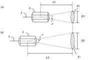
- FIG. 3 is a diagram showing the relationship between the axial movement of the scanning electromagnet and the width of the irradiation field.
- an irradiation field is formed by two-dimensionally scanning the irradiation target 11 with one of the plurality of divided layers (slices) with the charged particle beam 3.
- the irradiation field varies depending on the distance in the beam axis direction between one layer of the irradiation object 11 that is the irradiation position and the scanning electromagnet.
- FIG. 3A shows the case where the distance between one slice and the Y-direction scanning electromagnet 2 is L1
- FIG. 3B shows the case where the distance between the slice and the Y-direction scanning electromagnet 2 is L2.
- L1 ⁇ L2.
- the distances L1 and L2 are distances from the center of the magnetic pole of the scanning electromagnet 2 that scans the charged particle beam 3.
- FIG. 3A when the charged particle beam 3 is scanned at the maximum swing angle ⁇ , the scanning range length that is the length from one end of the scanning range 21 in the Y direction to the other end is D1.
- FIG. 3B when the charged particle beam 3 is scanned at the maximum swing angle ⁇ , the scanning range length that is the length from one end of the scanning range 21 in the Y direction to the other end is D2.
- the scanning range length D1 and the scanning range length D2 are expressed by Equation (1) and Equation (2).
- D1 2 ⁇ L1 ⁇ tan ⁇ (1)
- D2 2 ⁇ L2 ⁇ tan ⁇ (2) Since the distance L1 ⁇ the distance L2, the scanning range length D1 ⁇ the scanning range length D2. Therefore, when the distance in the beam axis direction between the irradiation position (one layer of the irradiation object 11) and the scanning electromagnet is increased, the scanning range 21 can be widened and the scanning range length can be increased. Further, when the distance in the beam axis direction between the irradiation position and the scanning electromagnet is reduced, the scanning range 21 can be narrowed and the scanning range length can be shortened.
- FIG. 4 is a diagram showing the relationship between the axial movement of the scanning electromagnet and the irradiation position error.
- the irradiation position error is a movement width determined by the positional accuracy of the charged particle beam 3 at the irradiation position, and changes depending on the distance in the beam axis direction between one layer of the irradiation target 11 that is the irradiation position and the scanning electromagnet.
- the positional accuracy of the charged particle beam 3 is determined by the magnetic field accuracy generated by the X-direction scanning electromagnet 1 and the Y-direction scanning electromagnet 2. Due to the magnetic field accuracy generated by the scanning electromagnets 1 and 2, the charged particle beam 3 changes within a range of the swing angle accuracy ⁇ with respect to a certain target irradiation position (target swing angle).
- 4A shows a case where the distance between one slice and the Y-direction scanning electromagnet 2 is L3
- FIG. 3B shows a case where the distance between the slice and the Y-direction scanning electromagnet 2 is L4. .
- L4 ⁇ L3.
- the distances L3 and L4 are distances from the magnetic pole center of the scanning electromagnet 2 that scans the charged particle beam 3.
- the irradiation position error is ⁇ X3.
- the irradiation position error is ⁇ X4.
- the accuracy of the swing angle is ⁇ .
- ⁇ X3 L3 ⁇ A
- ⁇ X4 L4 ⁇ A
- A tan ⁇ -tan ( ⁇ - ⁇ ). Since the distance L4 ⁇ the distance L3, the irradiation position error ⁇ X4 ⁇ the irradiation position error ⁇ X3.
- the irradiation position error increases and the irradiation position accuracy deteriorates.
- the distance in the beam axis direction between the irradiation position and the scanning electromagnet is reduced, the irradiation position error can be reduced and the irradiation position accuracy can be improved.
- spot when the size of an irradiation spot at the irradiation position of the charged particle beam 3 (hereinafter simply referred to as “spot” as appropriate) is small, a small interval (spot interval) is used to irradiate the irradiation target 11 with a predetermined dose without a gap. ), The irradiation position error requirement for each spot becomes severe.
- the irradiation spot is an irradiation unit divided in order to control the irradiation dose. For example, when the spot diameter is 5 mm, the irradiation position error request is 0.5 mm (10%) or less.
- the irradiation position error is 1 mm when the distance between the irradiation position and the beam axis direction of the scanning electromagnet is 5 m, the irradiation position error requirement of 0.5 mm or less for a spot diameter of 5 mm cannot be realized.
- the irradiation position error of 0.5 mm or less can be realized by setting the distance to 2.5 m or less.
- the charged particle beam 3 having a large spot size is irradiated at a large interval (spot interval).
- spot interval the distance between the irradiation position and the scanning electromagnet in the beam axis direction.
- the scanning range 21 can be widened, and the scanning range length can be increased. Therefore, by increasing the distance between the irradiation position and the scanning magnet in the beam axis direction, the spot size can be increased and a wide irradiation field can be formed.
- the particle beam irradiation apparatus 58 changes the distance between the X-direction scanning electromagnet 1 and the Y-direction scanning electromagnet 2 and the irradiation object 11 by the scanning electromagnet moving apparatus 4, thereby maximizing irradiation suitable for the irradiation object 11.
- Field and irradiation position accuracy can be selected.
- FIG. 5 is a diagram for explaining irradiation of the particle beam irradiation apparatus according to the first embodiment. 5 (a) to 5 (c) show three cases in which the distances between the X-direction scanning electromagnet 1 and the Y-direction scanning electromagnet 2 and the irradiation target 11 are different, and FIG. 5 (a) shows an intermediate distance.
- FIG. 5B shows a case where the distance is longer than that of FIG. 5A
- FIG. 5C shows a case where the distance is shorter than that of FIG. 5A
- 21a, 21b, and 21c are the maximum scanning ranges in each case
- 22a, 22b, and 22c indicate beam spots in each case.
- the scanning electromagnet moving device 4 moves the X-direction scanning electromagnet 1 and the Y-direction scanning electromagnet 2 in the direction of the beam axis of the charged particle beam 3 as shown in FIG. ) And move away from the irradiation target 11. Even if the irradiation object 11 is small or large, when the irradiation position error is desired to be small, the scanning electromagnet moving device 4 moves the X-direction scanning electromagnet 1 and the Y-direction scanning electromagnet 2 to the beam axis of the charged particle beam 3. In this direction, as shown in FIG. 5 (c), it moves in a direction approaching the irradiation object 11 to a position where a predetermined irradiation position accuracy can be achieved.
- the irradiation control device 8 generates control inputs (command currents) to the X-direction scanning electromagnet 1 and the Y-direction scanning electromagnet 2 based on the irradiation position accuracy and target position coordinates of the treatment plan data created by the treatment planning device.
- the irradiation control device 8 has a plurality of conversion tables and command value generation polynomials in order to correspond to predetermined irradiation position accuracy.
- the conversion table and the command value generation polynomial are control input generation units that generate control inputs.
- the case of using a conversion table is called a conversion table method
- the case of using a command value generating polynomial is called a polynomial method.
- the conversion table is a table of control input and irradiation position coordinates based on actual data of control input and actual irradiation position coordinates obtained by actual irradiation.
- the set current values of the X-direction scanning electromagnet 1 and the Y-direction scanning electromagnet 2 are calculated from the target position coordinates of the charged particle beam 3 using this conversion table.
- the control input sent to the scanning electromagnet power source 7 is a control input (command) for outputting a set current value obtained by calculation.
- a plurality of conversion tables having different irradiation position accuracy are prepared. That is, a plurality of conversion tables are prepared for each representative position accuracy. If there is something that matches the specified irradiation position accuracy, use the conversion table. If there is nothing that matches the specified irradiation position accuracy, complement the previous and next conversion table data (such as linear interpolation). Then, the irradiation control device 8 generates a control input.
- the command value generation polynomial is a measured value of the magnetic field of the X-direction scanning electromagnet 1 and the Y-direction scanning electromagnet 2 when actually irradiated and a polynomial of the measured irradiation position coordinates, and the excitation current and the magnetic field have a one-to-one relationship.
- the relationship between the target position coordinates of the charged particle beam 3 and the control input is expressed by a polynomial.
- Ix m 0 + m 1 xt + m 2 xt 2 + m 3 yt + m 4 xtyt + m 5 yt 2 ...
- Iy n 0 + n 1 xt + n 2 xt 2 + n 3 yt + n 4 xtyt + n 5 yt 2 ...
- m 0 to m 5 and n 0 to n 5 are parameter constants obtained by the least square method or the like.
- an interference term such as xtyt can be taken into consideration, and a control input Ic with higher accuracy than the conversion table method can be generated. Therefore, by applying the polynomial method, the irradiation position accuracy depending on the distance between the irradiation position and the scanning electromagnet can be further improved.
- a plurality of command value generation polynomials are prepared for each irradiation position accuracy depending on the distance between the irradiation position and the scanning electromagnet.
- Each selected irradiation position accuracy is a representative position accuracy. If there is something that matches the specified irradiation position accuracy, use the command value generation polynomial.If there is nothing that matches the specified irradiation position accuracy, use the data generated from the previous and next command value generation polynomials. Complementation (such as linear interpolation), the irradiation control device 8 generates a control input.
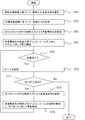
- FIG. 6 is a flowchart showing a control method of the particle beam irradiation apparatus according to the first embodiment.
- the particle beam irradiation device 58 selects a control input generation unit such as a conversion table to be used or a command value generation polynomial based on the irradiation position accuracy of the treatment plan data created by the treatment planning device (step ST1, control input generation). Part selection procedure).
- the selected control input generation unit generates a control input Ic (Ix, Iy) (step ST2, control input generation procedure).
- a dose determined in the treatment plan is irradiated to the irradiation object 11 by the charged particle beam 3 with respect to a certain spot in the treatment site.
- the scanning electromagnets 1 and 2 are excited by a control input for the certain spot.
- the irradiation control device 8 sends a control input corresponding to the position of a certain spot to the scanning electromagnet power source 7, and the scanning electromagnet power source 7 controls the X direction scanning electromagnet 1 and the Y direction scanning electromagnet 1 according to the control input.
- the scanning electromagnets 1 and 2 are excited by the excitation current designated by the control input.
- a setting completion signal is received from the X-direction scanning electromagnet 1 and the Y-direction scanning electromagnet 2, and the charged particle beam 3 is incident on the particle beam irradiation device 58 to the spot. Irradiation is started (step ST4).
- the irradiation controller 8 determines whether the irradiation according to the treatment plan has been performed on the spot, whether the irradiation dose detected by the dose monitor 5 has expired (whether the irradiation dose has reached the planned dose) (step ST5). ). If it has expired, the charged particle beam 3 is blocked (step ST6).
- the irradiation control device 8 determines whether there is a next spot. If there is a next spot, the process proceeds to step ST8, and if there is no next spot, the irradiation ends (step ST7). In step ST8, the scanning electromagnets 1 and 2 are excited by a control input for the next spot. It operates similarly to step ST3.
- step ST9 When the setting of the scanning electromagnets 1 and 2 is completed, the interruption of the charged particle beam 3 is released, and irradiation of the spot is started (step ST9). After performing the operation of step ST9, the process returns to step ST5. As described above, the process is repeated until the spot in one layer (slice) of the plurality of layers in the irradiation target 11 is completed. When irradiation to one slice is completed, the energy of the charged particle beam 3 is changed, and steps ST3 to ST9 are executed to irradiate other slices.
- the particle beam irradiation apparatus 58 changes the distance between the X-direction scanning electromagnet 1 and the Y-direction scanning electromagnet 2 and the irradiation object 11 by the scanning electromagnet moving apparatus 4, thereby maximizing irradiation suitable for the irradiation object 11.
- Field and irradiation position accuracy can be selected.
- the distance between the scanning electromagnet and the irradiation position is substantially fixed, and unlike the conventional case where the irradiation position accuracy at the irradiation position cannot be freely changed, the irradiation object 11
- the irradiation position accuracy can be appropriately changed according to the above.
- the combination of irradiation field and irradiation position accuracy can be varied, and various irradiation variations can be set.
- the particle beam irradiation device 58 of the first embodiment does not need to increase the irradiation position accuracy so much, and when it is desired to expand the maximum irradiation field, the scanning electromagnet moving device 4 is moved within the allowable irradiation position accuracy to perform X-direction scanning.
- a control input (command current) Ic for setting the excitation current of the electromagnet 1 and the Y-direction scanning electromagnet 2 is generated.
- the beam spot 22b becomes large, the number of spots to be irradiated on the irradiation object 11 is reduced as compared with the case where the beam spot is small. Can be shortened.
- the charged particle beam 3 may move in the vacuum duct to the vicinity of the irradiation target 11. is there.
- a metal such as a flange of a vacuum duct between the X-direction scanning electromagnet 1 and the Y-direction scanning electromagnet 2
- heat generation of the metal Is done.
- the distance between the X-direction scanning electromagnet 1 and the Y-direction scanning electromagnet 2 in the beam axis direction can be freely changed.
- the interval can be temporarily increased to prevent heat generation.
- the building that houses the particle beam irradiation device is built of reinforced concrete, and the height of the floor and ceiling may change due to aging or earthquake. Therefore, it is necessary to correct the position of the scanning electromagnet in the beam axis direction by periodically observing the displacement and keeping the distance between the scanning electromagnet and the irradiation position constant.
- the particle beam irradiation device 58 of the first embodiment can easily perform the position correction by the scanning electromagnet moving device 4.
- the scanning electromagnet moving device 4 has been described as an example in which the X direction scanning electromagnet 1 and the Y direction scanning electromagnet 2 are used in common, that is, the X direction scanning electromagnet 1 and the Y direction scanning electromagnet 2 are simultaneously moved.
- An independent scanning electromagnet moving device 4 may be provided.
- the scanning electromagnet moving device 4 is not limited to the configuration of the motor 12 and the ball screw 13 in the illustrated example, and an appropriate one can be employed.
- the configuration is as follows.
- the irradiation object 11 is large and the maximum irradiation field is to be increased, at least one of the X-direction scanning magnet 1 and the Y-direction scanning magnet 2 is moved in the direction of the beam axis of the charged particle beam 3 by the scanning electromagnet moving device 4. It moves in the direction away from the irradiation object 11 as shown in FIG. In the scanning direction of the scanning electromagnet that has moved away from the irradiation object 11, the maximum irradiation field is expanded.
- the scanning electromagnet moving device 4 In the direction of the beam axis of the beam 3, as shown in FIG. 5 (c), the beam 3 moves in a direction approaching the irradiation object 11 to a position where a predetermined irradiation position accuracy can be achieved.
- the irradiation position accuracy can be increased in the scanning direction of the scanning electromagnet that has moved in a direction approaching the irradiation object 11.
- the scanning electromagnets 1 and 2 that scan the charged particle beam 3, the scanning electromagnets 1 and 2 and the irradiation object 11 in the beam axis direction of the charged particle beam 3.
- the scanning electromagnet moving device 4 that moves the scanning electromagnets 1 and 2 to change the distance between the scanning electromagnet and the irradiation object in the beam axis direction of the charged particle beam can be changed.
- a variety of irradiation variations can be set by changing a combination of a plurality of parameters in particle beam irradiation such as a combination of irradiation position accuracy.
- the charged particle beam 3 is generated, the beam generator 52 that accelerates the charged particle beam 3 by the accelerator 54, and the charged particle beam 3 accelerated by the accelerator 54.
- a beam transport system 59 for transportation and a particle beam irradiation device 58 for irradiating the irradiation object 11 with the charged particle beam 3 transported by the beam transport system 59 are provided.
- the particle beam irradiation device 58 scans the charged particle beam 3.
- the scanning electromagnets 1 and 2 and the scanning electromagnet moving device 4 that moves the scanning electromagnets 1 and 2 to change the distance between the scanning electromagnets 1 and 2 and the irradiation target 11 in the beam axis direction of the charged particle beam 3 are provided.
- the distance between the scanning electromagnet in the beam axis direction of the charged particle beam and the irradiation target can be changed, and a plurality of particle beam irradiations such as combinations of irradiation field and irradiation position accuracy can be performed.
- the combination of parameters in the variable can be selected from a variety of illumination variations, it is possible to perform appropriate particle therapy.
- Embodiment 2 when moving at least one of the X-direction scanning electromagnet 1 and the Y-direction scanning electromagnet 2, the charged particle beam 3 swung by the maximum swing angle of the upstream scanning electromagnet 1 is It is conceivable to interfere with the magnetic poles of the scanning electromagnet 2.
- the second embodiment even when at least one of the X-direction scanning electromagnet 1 and the Y-direction scanning electromagnet 2 is moved, the charged particle beam 3 swung by the maximum swing angle of the upstream scanning electromagnet 1 is A magnetic pole moving device 29 is provided so as not to interfere with the magnetic poles of the scanning electromagnet 2.
- the irradiation apparatus of the first embodiment is different from that of the first embodiment in that a magnetic pole moving device 29 is installed at least in the Y-direction scanning electromagnet 2 on the downstream side.
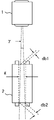
- FIG. 7 is a diagram for explaining the relationship between the magnetic pole of the scanning electromagnet and the charged particle beam.
- the charged particle beam 3 is scanned in the X direction at the swing angle ⁇ by the upstream X-direction scanning electromagnet 1.
- the downstream Y-direction scanning electromagnet 2 passes the magnetic pole interval g of the Y-direction scanning electromagnet 2.
- the charged particle beam 3 passes through the upper end moving range db1 at the upper end of the direction scanning electromagnet 2, and passes through the lower end moving range db2 at the lower end of the direction scanning electromagnet 2.
- the magnetic pole interval g needs to be wider than the lower end movement range db2. It is.
- the magnetic pole interval g is narrower than the lower end movement range db2, the charged particle beam 3 interferes with the magnetic poles of the Y-direction scanning electromagnet 2.
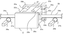
- FIG. 8 is a block diagram showing a scanning electromagnet according to Embodiment 2 of the present invention.
- FIG. 8 shows an example of the Y-direction scanning electromagnet 2 and the magnetic pole moving device 29.
- the Y-direction scanning electromagnet 2 has two fixed yokes 28a and 28b and two movable iron cores 23a and 23b. Movement guides 25a, 25b, 25c, 25d are provided on the fixed yokes 28a, 28b, and the movable iron cores 23a, 23b are moved by the magnetic pole moving device 29 while being supported by the movement guides 25a, 25b, 25c, 25d.
- the magnetic pole moving device 29 includes two moving parts that move the two movable iron cores 23a and 23b, respectively.
- the moving parts each include a pinion 27a (27b), a motor 26a (26b), and a rack 24a (24b).
- the rack 24a is attached to the movable iron core 23a
- the rack 24b is attached to the movable iron core 23ba.
- FIG. 8 shows the case where the magnetic pole interval between the movable iron core 23a and the movable iron core 23b is g1.
- the coil of the Y-direction scanning electromagnet 2 is installed around the convex portions 35a and 35b of the movable iron cores 23a and 23b.
- the coil installed on the movable iron core 23a moves with the movable iron core 23a
- the coil installed on the movable iron core 23b moves with the movable iron core 23b.
- FIG. 9 shows an example in which the magnetic pole spacing in the scanning electromagnet is maximized.
- each of the movable iron cores 23a and 23b moves to the maximum extent, and the magnetic pole interval between the movable iron core 23a and the movable iron core 23b is g2. Note that g1 ⁇ g2.
- the particle beam irradiation apparatus 58 of the second embodiment since the magnetic pole moving device 29 is installed at least in the downstream Y-direction scanning electromagnet 2 and the magnetic pole interval g of the downstream Y-direction scanning electromagnet 2 can be changed, the X-direction scanning is performed. Even when at least one of the electromagnet 1 and the Y-direction scanning electromagnet 2 is moved, the charged particle beam 3 can be prevented from interfering with the magnetic poles of the scanning electromagnet 2 on the downstream side. Therefore, the particle beam irradiation apparatus 58 of Embodiment 2 can select the maximum irradiation field and irradiation position accuracy suitable for the irradiation object 11 in one of the X direction and the Y direction. Since the maximum irradiation field and irradiation position accuracy can be selected in each of the X direction and the Y direction, various irradiation variations can be set as compared with the first embodiment.
- FIG. 10 is a block diagram showing a particle beam irradiation apparatus according to Embodiment 3 of the present invention.
- the particle beam irradiation apparatus 60 of Embodiment 3 is an example in which the distances between the irradiation object 11 and the X-direction scanning electromagnet 1 and the Y-direction scanning electromagnet 2 are discretely changed.
- FIG. 10 shows an example in which there are two scanning electromagnet pairs of an X direction scanning electromagnet and a Y direction scanning electromagnet.
- the particle beam irradiation apparatus 60 is different from the particle beam irradiation apparatus 58 of the first embodiment in that the X direction scanning electromagnet 1a and the Y direction scanning electromagnet 2a, the X direction scanning electromagnet 1b and the Y direction scanning electromagnet 2b, and two scanning electromagnets. 7a and 7b, and the two scanning electromagnet moving devices 30a and 30b.
- the electromagnet moving device 30a includes a fixed plate 31a for fixing the X-direction scanning electromagnet 1a and the Y-direction scanning electromagnet 2a, a rack 33a connected to the fixed plate 31a, a motor 32a, and a pinion 34a.
- the electromagnet moving device 30b includes a fixed plate 31b for fixing the X-direction scanning electromagnet 1b and the Y-direction scanning electromagnet 2b, a rack 33b connected to the fixed plate 31b, a motor 32b, and a pinion 34b. As the pinion 34a attached to the motor 32a rotates, the rack 33a moves. Similarly, the pinion 34b attached to the motor 32b rotates, so that the rack 33b moves.
- the scanning electromagnet moving devices 30a and 30b are devices that move from a position where the charged particle beam 3 is scanned to a position where the charged particle beam 3 is not scanned.
- the distance between the irradiation object 11 and the X-direction scanning electromagnet 1 and the Y-direction scanning electromagnet 2 is changed discretely by the scanning electromagnet moving devices 30a and 30b, so that control according to the number of discrete changes is made.
- An input generation unit may be prepared. Since the particle beam irradiation apparatus 60 according to the third embodiment uses a smaller number of control input generation units than the particle beam irradiation apparatus 58 according to the first embodiment, the amount of work for preparing the control input generation units can be reduced. The period until the actual operation of the particle beam irradiation apparatus is started can be shortened.
- the particle beam irradiation apparatus 60 according to the third embodiment is less diverse than the particle beam irradiation apparatus 58 according to the first embodiment, but unlike the conventional case, the particle beam irradiation such as a combination of irradiation field and irradiation position accuracy is used.
- the combination of a plurality of parameters in can be made variable, and various irradiation variations can be set.
- spot scanning method has been described as an example, it can be applied to raster scanning.
- the scanning electromagnet moving device 4 or the scanning electromagnet moving device 30 can be applied to broad irradiation method.
- the distance between the irradiation object 11 and the wobbler electromagnet can be changed to increase the irradiation field.
- the combination of the irradiation field and the irradiation position accuracy can be varied as a combination of a plurality of parameters in particle beam irradiation, and various irradiation variations can be performed.
- a combination of parameters a combination of an irradiation field and a flatness of a beam can be varied, and various irradiation variations can be performed.
Abstract
Description
図1は本発明の粒子線治療装置の概略構成図である。粒子線治療装置51は、ビーム発生装置52と、ビーム輸送系59と、粒子線照射装置58a、58b(又は60a、60b)とを備える。ビーム発生装置52は、イオン源(図示せず)と、前段加速器53と、シンクロトロン54とを有する。粒子線照射装置58b(60b)は回転ガントリ(図示せず)に設置される。粒子線照射装置58a(60a)は回転ガントリを有しない治療室に設置される。ビーム輸送系59の役割はシンクロトロン54と粒子線照射装置58a、58bの連絡にある。ビーム輸送系59の一部は回転ガントリ(図示せず)に設置され、その部分には複数の偏向電磁石55a、55b、55cを有する。
D1=2×L1×tanα ・・・(1)
D2=2×L2×tanα ・・・(2)
距離L1<距離L2なので、走査範囲長D1<走査範囲長D2となる。したがって、照射位置(照射対象11の1つの層)と走査電磁石との間のビーム軸方向の距離を大きくする場合は、走査範囲21を広くでき、走査範囲長を長くすることができる。また、照射位置と走査電磁石との間のビーム軸方向の距離を小さくする場合は、走査範囲21を狭くでき、走査範囲長を短くすることができる。
ΔX3=L3×A ・・・(3)
ΔX4=L4×A ・・・(4)
ここで、A=tanβ-tan(β-Δθ)である。距離L4<距離L3なので、照射位置誤差ΔX4<照射位置誤差ΔX3となる。したがって、照射位置(照射対象11の1つの層)と走査電磁石との間のビーム軸方向の距離を大きくする場合は、照射位置誤差が大きくなり、照射位置精度が悪くなる。一方、照射位置と走査電磁石との間のビーム軸方向の距離を小さくする場合は、照射位置誤差を小さくすることができ、照射位置精度を向上することができる。
Ix=m0+m1xt+m2xt2+m3yt+m4xtyt+m5yt2
・・・(5)
Iy=n0+n1xt+n2xt2+n3yt+n4xtyt+n5yt2
・・・(6)
ここで、m0~m5、n0~n5は、最小二乗法などにより求めたパラメータ定数である。この多項式方式では、xtytのような干渉項も考慮でき、変換テーブル方式よりも精度の高い制御入力Icを生成できる。したがって、多項式方式を適用することで、照射位置と走査電磁石との距離に依存する照射位置精度をさらに向上させることができる。
実施の形態1では、X方向走査電磁石1及びY方向走査電磁石2の少なくとも一方を移動させる場合に、上流側の走査用電磁石1の最大振り角によって振られた荷電粒子ビーム3が、下流側の走査用電磁石2の磁極と干渉することが考えられる。実施の形態2では、X方向走査電磁石1及びY方向走査電磁石2の少なくとも一方を移動させる場合でも、上流側の走査用電磁石1の最大振り角によって振られた荷電粒子ビーム3が、下流側の走査用電磁石2の磁極と干渉しないように磁極移動装置29を備える。実施の形態1の照射装置とは、少なくとも下流側のY方向走査電磁石2に磁極移動装置29が設置される点で異なる。
図10は本発明の実施の形態3による粒子線照射装置を示す構成図である。実施の形態3の粒子線照射装置60は、照射対象11とX方向走査電磁石1及びY方向走査電磁石2との距離を離散的に変更させる例である。図10では、X方向走査電磁石及びY方向走査電磁石の走査電磁石対が2つある例を示している。粒子線照射装置60は、実施の形態1の粒子線照射装置58とは、X方向走査電磁石1a及びY方向走査電磁石2aと、X方向走査電磁石1b及びY方向走査電磁石2bと、2つの走査電磁石7a、7bと、2つの走査電磁石移動装置30a、30bを有する点で異なる。
Claims (10)
- 加速器により加速された荷電粒子ビームを照射対象に照射する粒子線照射装置であって、
前記荷電粒子ビームをビーム軸に垂直なX方向及びY方向に走査する走査電磁石と、
前記荷電粒子ビームのビーム軸方向における前記走査電磁石と前記照射対象との距離を変更するように前記走査電磁石を移動する走査電磁石移動装置と、を備えた粒子線照射装置。 - 前記荷電粒子ビームの目標照射位置座標に基づいて前記走査電磁石を制御する照射制御装置を備え、
前記照射制御装置は、前記走査電磁石と前記照射対象との距離に基づいて、前記走査電磁石を制御する制御入力を生成することを特徴とする請求項1記載の粒子線照射装置。 - 前記照射制御装置は、前記走査電磁石と前記照射対象との距離に基づく制御入力を生成する制御入力生成部を有することを特徴とする請求項2記載の粒子線照射装置。
- 前記照射制御装置は、前記走査電磁石と前記照射対象との距離に基づく照射位置精度が異なる複数の前記制御入力生成部を有することを特徴とする請求項3記載の粒子線照射装置。
- 前記制御入力生成部は、前記制御入力と前記制御入力に対応する前記目標照射位置座標とが関係付けられた変換テーブルであることを特徴とする請求項3または4に記載の粒子線照射装置。
- 前記制御入力生成部は、前記制御入力と前記目標照射位置座標とが関係付けられた多項式であることを特徴とする請求項3または4に記載の粒子線照射装置。
- 前記走査電磁石は、前記荷電粒子ビームをX方向及びY方向に走査する第1の走査電磁石と、
前記第1の走査電磁石の下流に配置され、前記荷電粒子ビームをX方向及びY方向に走査する第2の走査電磁石とを含み、
前記走査電磁石移動装置は、前記第1の走査電磁石を、前記荷電粒子ビームを走査する位置から前記荷電粒子ビームを走査しない位置までの間を移動させる走査電磁石移動装置と、
前記第2の走査電磁石を、前記荷電粒子ビームを走査する位置から前記荷電粒子ビームを走査しない位置までの間を移動させる走査電磁石移動装置とを含み、
前記第1の走査電磁石または前記第2の走査電磁石のいずれか一方により前記荷電粒子ビームは走査されることを特徴とする請求項1乃至6のいずれか1項に記載の粒子線照射装置。 - 前記走査電磁石は、前記荷電粒子ビームをX方向に走査するX方向走査電磁石と、前記X方向走査電磁石の下流側に配置され、前記荷電粒子ビームをY方向に走査するY方向走査電磁石とを含み、
前記Y方向走査電磁石は、磁極間隔が変更可能な可動鉄心を有し、
前記Y方向走査電磁石の前記可動鉄心を移動する磁極移動装置を備えたことを特徴とする請求項1乃至6のいずれか1項に記載の粒子線照射装置。 - 前記第1の走査電磁石または前記第2の走査電磁石は、前記荷電粒子ビームをX方向に走査するX方向走査電磁石と、前記X方向走査電磁石の下流側に配置され、前記荷電粒子ビームをY方向に走査するY方向走査電磁石とを含み、
前記Y方向走査電磁石は、磁極間隔が変更可能な可動鉄心を有し、
前記Y方向走査電磁石の前記可動鉄心を移動する磁極移動装置を備えたことを特徴とする請求項7記載の粒子線照射装置。 - 荷電粒子ビームを発生させ、この荷電粒子ビームを加速器で加速させるビーム発生装置と、前記加速器により加速された荷電粒子ビームを輸送するビーム輸送系と、前記ビーム輸送系で輸送された荷電粒子ビームを照射対象に照射する粒子線照射装置とを備え、
前記粒子線照射装置は、請求項1乃至9のいずれか1項に記載の粒子線照射装置であることを特徴とする粒子線治療装置。
Priority Applications (6)
| Application Number | Priority Date | Filing Date | Title |
|---|---|---|---|
| JP2010543241A JP4673450B1 (ja) | 2010-08-20 | 2010-08-20 | 粒子線照射装置及び粒子線治療装置 |
| PCT/JP2010/064073 WO2012023205A1 (ja) | 2010-08-20 | 2010-08-20 | 粒子線照射装置及び粒子線治療装置 |
| EP10856162.2A EP2572756B1 (en) | 2010-08-20 | 2010-08-20 | Particle beam-irradiating device and particle beam therapy device |
| US13/702,419 US8604444B2 (en) | 2010-08-20 | 2010-08-20 | Particle beam irradiation apparatus and particle beam therapy system |
| CN201080068538.6A CN103079641B (zh) | 2010-08-20 | 2010-08-20 | 粒子射线照射装置及粒子射线治疗装置 |
| TW099140509A TWI426530B (zh) | 2010-08-20 | 2010-11-24 | 粒子束照射裝置及粒子束治療裝置 |
Applications Claiming Priority (1)
| Application Number | Priority Date | Filing Date | Title |
|---|---|---|---|
| PCT/JP2010/064073 WO2012023205A1 (ja) | 2010-08-20 | 2010-08-20 | 粒子線照射装置及び粒子線治療装置 |
Publications (1)
| Publication Number | Publication Date |
|---|---|
| WO2012023205A1 true WO2012023205A1 (ja) | 2012-02-23 |
Family
ID=44080018
Family Applications (1)
| Application Number | Title | Priority Date | Filing Date |
|---|---|---|---|
| PCT/JP2010/064073 WO2012023205A1 (ja) | 2010-08-20 | 2010-08-20 | 粒子線照射装置及び粒子線治療装置 |
Country Status (6)
| Country | Link |
|---|---|
| US (1) | US8604444B2 (ja) |
| EP (1) | EP2572756B1 (ja) |
| JP (1) | JP4673450B1 (ja) |
| CN (1) | CN103079641B (ja) |
| TW (1) | TWI426530B (ja) |
| WO (1) | WO2012023205A1 (ja) |
Cited By (1)
| Publication number | Priority date | Publication date | Assignee | Title |
|---|---|---|---|---|
| JP2020508157A (ja) * | 2017-02-23 | 2020-03-19 | メビオン・メディカル・システムズ・インコーポレーテッド | 粒子線治療における自動処置 |
Families Citing this family (7)
| Publication number | Priority date | Publication date | Assignee | Title |
|---|---|---|---|---|
| CN104217779B (zh) * | 2014-09-15 | 2015-09-23 | 华中科技大学 | 一种电子束扩散截面修整装置及方法 |
| US11027151B2 (en) * | 2016-03-10 | 2021-06-08 | William Beaumont Hospital | Particle arc therapy |
| WO2018047272A1 (ja) * | 2016-09-08 | 2018-03-15 | 三菱電機株式会社 | 走査電磁石、および走査電磁石を備えた粒子線照射装置の製造方法 |
| US10786687B2 (en) * | 2018-09-28 | 2020-09-29 | Varian Medical Systems, Inc | Method and apparatus for performing irradiation time optimization for intensity modulated proton therapy during treatment planning while maintaining acceptable irradiation plan quality |
| JP7165559B2 (ja) | 2018-10-23 | 2022-11-04 | 住友重機械工業株式会社 | 治療計画システム |
| JP7437491B2 (ja) * | 2019-09-25 | 2024-02-22 | 中硼(厦▲門▼)医▲療▼器械有限公司 | 照射パラメータ選択装置及びその使用方法、該装置を含む制御システム及びその使用方法 |
| CN113082550B (zh) * | 2021-03-26 | 2022-12-06 | 中以康联国际医疗科技有限公司 | 粒子射束监控方法及粒子射束治疗装置 |
Citations (4)
| Publication number | Priority date | Publication date | Assignee | Title |
|---|---|---|---|---|
| JPH08257148A (ja) | 1995-03-24 | 1996-10-08 | Hitachi Ltd | 回転ガントリ |
| JP2004321830A (ja) * | 2002-06-12 | 2004-11-18 | Hitachi Ltd | 粒子線照射装置及び照射野形成装置の調整方法 |
| JP4393581B1 (ja) * | 2009-04-24 | 2010-01-06 | 三菱電機株式会社 | 粒子線治療装置 |
| JP2010029594A (ja) * | 2008-07-31 | 2010-02-12 | Natl Inst Of Radiological Sciences | 粒子線照射装置及び治療計画装置 |
Family Cites Families (10)
| Publication number | Priority date | Publication date | Assignee | Title |
|---|---|---|---|---|
| DE2029005A1 (de) * | 1970-06-12 | 1971-12-16 | Licentia Gmbh | Anordnung zur Strahlen insbesondere Neutronenstrahltherapie |
| US5511549A (en) * | 1995-02-13 | 1996-04-30 | Loma Linda Medical Center | Normalizing and calibrating therapeutic radiation delivery systems |
| JP3178381B2 (ja) * | 1997-02-07 | 2001-06-18 | 株式会社日立製作所 | 荷電粒子照射装置 |
| JP3338332B2 (ja) | 1997-05-28 | 2002-10-28 | 三菱電機株式会社 | 荷電粒子照射装置 |
| JP3528583B2 (ja) * | 1997-12-25 | 2004-05-17 | 三菱電機株式会社 | 荷電粒子ビーム照射装置および磁界発生装置 |
| JP4378396B2 (ja) * | 2007-06-22 | 2009-12-02 | 株式会社日立製作所 | 粒子線照射システム |
| JP5430115B2 (ja) * | 2008-10-15 | 2014-02-26 | 三菱電機株式会社 | 荷電粒子線ビームのスキャニング照射装置 |
| US8350234B2 (en) * | 2008-12-24 | 2013-01-08 | Mitsubishi Electric Corporation | Particle beam therapy system |
| JP4499829B1 (ja) * | 2009-06-09 | 2010-07-07 | 三菱電機株式会社 | 粒子線治療装置および粒子線治療装置の調整方法 |
| WO2011148486A1 (ja) * | 2010-05-27 | 2011-12-01 | 三菱電機株式会社 | 粒子線照射システムおよび粒子線照射システムの制御方法 |
-
2010
- 2010-08-20 US US13/702,419 patent/US8604444B2/en active Active
- 2010-08-20 CN CN201080068538.6A patent/CN103079641B/zh not_active Expired - Fee Related
- 2010-08-20 EP EP10856162.2A patent/EP2572756B1/en not_active Not-in-force
- 2010-08-20 JP JP2010543241A patent/JP4673450B1/ja active Active
- 2010-08-20 WO PCT/JP2010/064073 patent/WO2012023205A1/ja active Application Filing
- 2010-11-24 TW TW099140509A patent/TWI426530B/zh not_active IP Right Cessation
Patent Citations (4)
| Publication number | Priority date | Publication date | Assignee | Title |
|---|---|---|---|---|
| JPH08257148A (ja) | 1995-03-24 | 1996-10-08 | Hitachi Ltd | 回転ガントリ |
| JP2004321830A (ja) * | 2002-06-12 | 2004-11-18 | Hitachi Ltd | 粒子線照射装置及び照射野形成装置の調整方法 |
| JP2010029594A (ja) * | 2008-07-31 | 2010-02-12 | Natl Inst Of Radiological Sciences | 粒子線照射装置及び治療計画装置 |
| JP4393581B1 (ja) * | 2009-04-24 | 2010-01-06 | 三菱電機株式会社 | 粒子線治療装置 |
Non-Patent Citations (1)
| Title |
|---|
| See also references of EP2572756A4 |
Cited By (5)
| Publication number | Priority date | Publication date | Assignee | Title |
|---|---|---|---|---|
| JP2020508157A (ja) * | 2017-02-23 | 2020-03-19 | メビオン・メディカル・システムズ・インコーポレーテッド | 粒子線治療における自動処置 |
| US11103730B2 (en) | 2017-02-23 | 2021-08-31 | Mevion Medical Systems, Inc. | Automated treatment in particle therapy |
| JP2022002712A (ja) * | 2017-02-23 | 2022-01-11 | メビオン・メディカル・システムズ・インコーポレーテッド | 粒子線治療における自動処置 |
| JP7002556B2 (ja) | 2017-02-23 | 2022-01-20 | メビオン・メディカル・システムズ・インコーポレーテッド | 粒子線治療における自動処置 |
| JP7416742B2 (ja) | 2017-02-23 | 2024-01-17 | メビオン・メディカル・システムズ・インコーポレーテッド | 粒子線治療における自動処置 |
Also Published As
| Publication number | Publication date |
|---|---|
| CN103079641B (zh) | 2015-07-22 |
| CN103079641A (zh) | 2013-05-01 |
| JP4673450B1 (ja) | 2011-04-20 |
| US20130075622A1 (en) | 2013-03-28 |
| TWI426530B (zh) | 2014-02-11 |
| TW201209846A (en) | 2012-03-01 |
| JPWO2012023205A1 (ja) | 2013-10-28 |
| US8604444B2 (en) | 2013-12-10 |
| EP2572756A1 (en) | 2013-03-27 |
| EP2572756A4 (en) | 2014-03-05 |
| EP2572756B1 (en) | 2015-03-04 |
Similar Documents
| Publication | Publication Date | Title |
|---|---|---|
| JP4673450B1 (ja) | 粒子線照射装置及び粒子線治療装置 | |
| JP5646312B2 (ja) | 粒子線照射装置及び粒子線治療装置 | |
| JP4954351B2 (ja) | 粒子線照射システムおよび粒子線照射方法 | |
| WO2012099023A1 (ja) | エネルギーデグレーダ、及びそれを備えた荷電粒子照射システム | |
| JP5610404B2 (ja) | ビーム照射装置、ビーム照射制御方法及び重粒子線治療装置 | |
| JP6527241B2 (ja) | 粒子線治療システム | |
| JP2015097683A (ja) | 粒子線治療システム | |
| JP5130175B2 (ja) | 粒子線照射システム及びこの制御方法 | |
| JP5511699B2 (ja) | 粒子線照射装置及び粒子線治療装置 | |
| JP5350307B2 (ja) | 粒子線治療システム | |
| JP6266092B2 (ja) | 粒子線治療装置 | |
| JP2012029821A (ja) | 粒子線治療システム及び粒子線照射方法 | |
| JP6494808B2 (ja) | 粒子線治療装置 | |
| JP3964769B2 (ja) | 医療用荷電粒子照射装置 | |
| CN112334187B (zh) | 用于放射治疗系统的束传输线及其放射治疗系统 | |
| JP2013153993A (ja) | 粒子線治療装置 | |
| JP2022083625A (ja) | 荷電粒子線治療装置 | |
| WO2016104040A1 (ja) | 粒子線照射装置および粒子線照射装置の制御方法 | |
| JP2016105844A (ja) | 治療計画装置及び粒子線治療装置 |
Legal Events
| Date | Code | Title | Description |
|---|---|---|---|
| WWE | Wipo information: entry into national phase |
Ref document number: 201080068538.6 Country of ref document: CN |
|
| WWE | Wipo information: entry into national phase |
Ref document number: 2010543241 Country of ref document: JP |
|
| 121 | Ep: the epo has been informed by wipo that ep was designated in this application |
Ref document number: 10856162 Country of ref document: EP Kind code of ref document: A1 |
|
| WWE | Wipo information: entry into national phase |
Ref document number: 13702419 Country of ref document: US |
|
| WWE | Wipo information: entry into national phase |
Ref document number: 2010856162 Country of ref document: EP |
|
| NENP | Non-entry into the national phase |
Ref country code: DE |